Embed Size (px)
Citation preview
SIMATIC Help on SFC Visualization
What's new in SFV? 1
SFC Visualization (SFV)
2
Basic SFC settings
3
Configuration
4
Operating and monitoring SFCs
5
Appendix
6
SIMATIC
Process Control System PCS 7SFC Visualization
Programming and Operating Manual
03/2009 A5E02113403-01
Legal information Legal information Warning notice system
This manual contains notices you have to observe in order to ensure your personal safety, as well as to prevent damage to property. The notices referring to your personal safety are highlighted in the manual by a safety alert symbol, notices referring only to property damage have no safety alert symbol. These notices shown below are graded according to the degree of danger.
DANGER indicates that death or severe personal injury will result if proper precautions are not taken.
WARNING indicates that death or severe personal injury may result if proper precautions are not taken.
CAUTION with a safety alert symbol, indicates that minor personal injury can result if proper precautions are not taken.
CAUTION without a safety alert symbol, indicates that property damage can result if proper precautions are not taken.
NOTICE indicates that an unintended result or situation can occur if the corresponding information is not taken into account.
If more than one degree of danger is present, the warning notice representing the highest degree of danger will be used. A notice warning of injury to persons with a safety alert symbol may also include a warning relating to property damage.
Qualified Personnel The device/system may only be set up and used in conjunction with this documentation. Commissioning and operation of a device/system may only be performed by qualified personnel. Within the context of the safety notes in this documentation qualified persons are defined as persons who are authorized to commission, ground and label devices, systems and circuits in accordance with established safety practices and standards.
Proper use of Siemens products Note the following:
WARNING Siemens products may only be used for the applications described in the catalog and in the relevant technical documentation. If products and components from other manufacturers are used, these must be recommended or approved by Siemens. Proper transport, storage, installation, assembly, commissioning, operation and maintenance are required to ensure that the products operate safely and without any problems. The permissible ambient conditions must be adhered to. The information in the relevant documentation must be observed.
Trademarks All names identified by ® are registered trademarks of the Siemens AG. The remaining trademarks in this publication may be trademarks whose use by third parties for their own purposes could violate the rights of the owner.
Disclaimer of Liability We have reviewed the contents of this publication to ensure consistency with the hardware and software described. Since variance cannot be precluded entirely, we cannot guarantee full consistency. However, the information in this publication is reviewed regularly and any necessary corrections are included in subsequent editions.
Siemens AG Industry Sector Postfach 48 48 90026 NÜRNBERG GERMANY
A5E02113403-01 Ⓟ 12/2008
Copyright © Siemens AG 2009. Technical data subject to change
SFC Visualization Programming and Operating Manual, 03/2009, A5E02113403-01 3
Table of contents
1 What's new in SFV?................................................................................................................................... 5 2 SFC Visualization (SFV) ............................................................................................................................ 7 3 Basic SFC settings .................................................................................................................................... 9 4 Configuration ........................................................................................................................................... 11
4.1 Configurations for SFC Visualization ...........................................................................................11 4.2 Configuring SFC block icons........................................................................................................12 4.3 Configuring SFC faceplates .........................................................................................................14 4.4 Adapting faceplates .....................................................................................................................15 4.5 Preparing the controls..................................................................................................................16 4.6 Configuring the "PCS7 SFC Control" status display....................................................................17 4.7 Configuring the "PCS7 SFC MultiChart Control" status display ..................................................18 4.8 Configuring the SFC button .........................................................................................................20 4.9 Configuring the SFC browser selection .......................................................................................21 4.10 Using functions for user-specific scripts (SFC API Calls) ............................................................22 4.11 OS Server and OS Client.............................................................................................................23 4.11.1 What you should know about OS Server and OS Client .............................................................23
5 Operating and monitoring SFCs .............................................................................................................. 25 5.1 Access control..............................................................................................................................25 5.2 Operating and monitoring the SFC by means of faceplate..........................................................26 5.3 SFC chart faceplate, "Standard" view..........................................................................................27 5.4 "SFC Chart" faceplate, "Messages" view.....................................................................................28 5.5 "SFC Instance" faceplate, "Actual Values" view ..........................................................................29 5.6 "SFC Instance" faceplate, "Block contacts" view.........................................................................33 5.7 "SFC Instance" faceplate, "Prepared Values" view .....................................................................34 5.8 "SFC Instance" faceplate, "Parameters" view .............................................................................35 5.9 "SFC Instance" faceplate, "Messages" view................................................................................36 5.10 "SFC Instance" faceplate, "Batch" view.......................................................................................37 5.11 Operating and monitoring the SFC by means of SFC status display ..........................................38 5.12 PCS 7 SFC Control......................................................................................................................39 5.13 PCS 7 SFC MultiChart Control ....................................................................................................41 5.14 Visualizing the SFC status by means of SFC selection button in the button set or by
means of SFC browser selection in the picture ...........................................................................45
Table of contents
SFC Visualization 4 Programming and Operating Manual, 03/2009, A5E02113403-01
5.15 Information and operator input in the detail view ........................................................................ 46 5.16 Setting the operating mode......................................................................................................... 50 5.17 Setting the operating state .......................................................................................................... 51 5.18 Setting step control mode ........................................................................................................... 52 5.19 Setting the sequence options...................................................................................................... 53 5.20 Acknowledging operator requests and step errors ..................................................................... 54 5.21 "Properties" dialog boxes ............................................................................................................ 55 5.22 "Properties" Dialog Box for the Sequencer ................................................................................. 56 5.23 "Properties" dialog box of the start condition .............................................................................. 57 5.24 "Properties" Dialog Box for the Step ........................................................................................... 58 5.25 "Properties" Dialog Box for the Transition................................................................................... 60 5.26 Messages.................................................................................................................................... 61 5.27 Operating state logic ................................................................................................................... 62 5.27.1 Operating state logic for SFC (SFC OSL)................................................................................... 62 5.27.2 Operating state logic for sequencers (sequencer OSL).............................................................. 65 5.28 Operating and monitoring using the Web Client ......................................................................... 68 5.28.1 Running SFC Visualization on the Web Client............................................................................ 68
6 Appendix.................................................................................................................................................. 69 6.1 SFC system tag........................................................................................................................... 69 6.2 SFC API functions....................................................................................................................... 70 6.3 Operating state icons .................................................................................................................. 73
Index........................................................................................................................................................ 75
SFC Visualization Programming and Operating Manual, 03/2009, A5E02113403-01 5
What's new in SFV? 1Enhancements/changes in V7.1
Version V7.1 contains the following enhancements or changes compared to version V7.0: ● New "Block contacts" view
There is a new "Block contacts" view for the faceplate of an SFC instance. This means the name, block type, and status of each block contact will be displayed. You open the associated faceplate with a button.
Enhancements / changes in V7.0 Version 7.0 contains the following enhancements or changes compared to version V6.x: ● Session log
A button for the user-specific session log has been added to the title bar of the SFC window. The different representation of the button icon shows whether or not the current position coincides with the saved position. For further information, refer to the section: Information and Operator Inputs in the Detailed Window (Page 46).
● Automatic update The overview screen now automatically changes to the active sequencer if the "Update" option is activated. You can activate this option in the detail view or in the object properties of the steps and transitions.
● Enhanced MultiChart Control MultiChart Control has been expanded with additional views (control strategy, group display) and with a button for calling the faceplate. A button for setting filters was added to the column headers.
● Visualization of the OS comment The detail view now includes the OS comment. The comment is output on the right side of the step or transition. The acknowledgement keys are now visualized on the left side as in SFC test mode.
● Block comment in operating message The block comment is output in an operating message generated by the WinCC message system, depending on the setting.
● Jump to picture from step or transition A button was added to the object properties of sequencers, steps, transitions and start conditions which can be used to open the WinCC picture which contains the associated process tag.

What's new in SFV?
SFC Visualization 6 Programming and Operating Manual, 03/2009, A5E02113403-01
● Displaying acknowledgment information If configured in the SFC, the acknowledgement information is output to the operator next to the button for acknowledging operator requests in "T/T and O" step control mode.
● SFC settings The "Group display" tab has been added to the SFC global settings dialog box.
SFC Visualization Programming and Operating Manual, 03/2009, A5E02113403-01 7
SFC Visualization (SFV) 2Introduction
You can use the "SFC Visualization" software package to configure SFC visualization in WinCC and to perform operator control and monitoring of SFC charts and SFC instances in the WinCC runtime system.
What is SFC? SFC (Sequential Function Chart) is a sequential control system that is used for control flow-oriented process control. A sequential control system is a controller with automatic, step-wise execution. It switches from one state to the next depending on conditions.
Note In this manual, we generally refer to the SFC charts and SFC instances as SFCs, unless these objects need to be distinguished in the respective context.
What does the SFC Engineering System offer? The engineering system allows you to create SFC charts, SFC types and SFC instances, compile and download them to the CPU, and test and commission them. In order to be able to use the SFCs in the runtime system, you must transfer them to the runtime system from the engineering system using the "AS-OS-Engineering" software package. You can also transfer charts individually. You transfer the SFCs with their OS comments and configured messages. Mechanisms are stored with the messages that enable you to directly access the SFC that the message pertains to. You can also perform the following actions: ● Configure the display of SFCs ● Configure global operator authorizations for the SFCs and specific operator
authorizations for each SFC ● Place objects in the WinCC display for calling the SFCs You will find more information in the SFC Sequential Function Chart Manual in the SIMATIC STEP 7 User Manual and in the corresponding online help.

SFC Visualization (SFV)
SFC Visualization 8 Programming and Operating Manual, 03/2009, A5E02113403-01
What does the Runtime system for SFC offer? The runtime system enables simultaneous operator control and monitoring of any number of SFCs.
Note ● Configuration is not possible during runtime operation. ● You can transfer SFCs to the runtime system even while the OS is running. This may
cause a temporary inconsistency in the displays, since the SFCs must first be downloaded to the automation system before being loaded on the OS. The potential for inconsistencies during this period is unavoidable.
SFC Visualization Programming and Operating Manual, 03/2009, A5E02113403-01 9
Basic SFC settings 3Settings in WinCC Explorer
The general settings for the visualization of SFC charts and SFC instances within the runtime system are made in WinCC Explorer. You can make these changes globally for all displayed SFCs or for specific objects.
Global Settings Global settings for displaying SFCs affect the following areas: ● Topology ● Colors ● Authorization level ● Group display To open the "SFC" dialog, select "SFC" in the WinCC Explorer and open the context menu. Then, select the menu command Open. You can specify the size of the objects and the distance between them for the topology in the detail area and overview area. You choose colors to distinguish the states of steps, transitions and selected objects in the display. You change the authorization levels for operator inputs if you require levels other than the default levels ("Monitoring", "Process Operation" and "Advanced Process Operation"). These settings apply to all SFCs in the relevant WinCC project, unless specific authorization levels have been set for the SFC in question. These authorizations remain in place following OS compilation. In order to grant a user the authorization to perform operator inputs in SFC Visualization, the corresponding authorization levels must be enabled for this user (globally or area-specific) in the User Administrator. If no users are configured, all operator inputs are permitted without restriction. In this case, the "Authorization Levels" tab is not available. To access the configuration for the group display, choose the "Group Display Properties" button on the "Group Display" tab.
Basic SFC settings
SFC Visualization 10 Programming and Operating Manual, 03/2009, A5E02113403-01
In the Group Display window, the following additional tabs are available: Tab Setting Geometry Size of the display fields Colors Background color of the display fields Style 3D frame width (in pixels) Font Font attributes (font, alignment etc.) Flashing Flashing frequency Other Other attributes, such as enabled for operator, group relevant, display, group value and
acknowledgment pattern Message types
Display text and attributes (font color, background color, flashing) for the individual message statuses
Lock Whether the messages are output or locked. An "x" (default setting) appears in the display field to indicate that messages are locked. You can change the default setting.
Assignment Message type for each display field
Object-Based Settings (on server only) You can make the following settings individually for each SFC: ● Configuring the update cycle ● Configuring the standard view.
This is the overview window or detail window with which the SFC is opened. ● Configuring the operator authorization levels The available SFCs are displayed in the detail window of WinCC Explorer when "SFC" is selected. To edit object-based settings, open the context menu of the selected SFC and select the menu command Properties.
SFC Visualization Programming and Operating Manual, 03/2009, A5E02113403-01 11
Configuration 44.1 Configurations for SFC Visualization
Introduction You can place objects in a WinCC display that enable you to open an SFC during runtime operation. The following objects can be used for this: ● Block icons ● "PCS 7 SFC Control" ● "PCS 7 SFC MultiChart Control" ● Any graphic object (such as a rectangle) ● A Windows object (such as a button)
Preparation ● Select the Options > 'Compile Multiple OSs' Wizard' > Start... command in SIMATIC
Manager in order to transfer the SFC charts and SFC instances to the OS. ● Then, carry out the Preparations for the Controls (Page 16).
Note The "@PCS 7 SFC Panel Control" and "@PCS 7 SFC SP Control" controls, which are supplied with SFC Visualization, are the internal controls required in SFC Visualization. They have not yet been approved for use in WinCC pictures.
You can configure the following objects for opening the SFC: Configuring SFC Block Icons (Page 12) Configuring SFC Faceplates (Page 14) Configuring the "PCS 7 SFC Control" Status Display (Page 17) Configuring the "PCS 7 SFC MultiChart Control" Status Display (Page 18) Configuring an SFC Button (Page 20) Configuring the SFC Browser Selection (Page 21) You can use SFC Visualization functions in order to create your own scripts. For additional information please refer to the Using Functions for Custom Scripts (Page 22).
Configuration 4.2 Configuring SFC block icons
SFC Visualization 12 Programming and Operating Manual, 03/2009, A5E02113403-01
4.2 Configuring SFC block icons
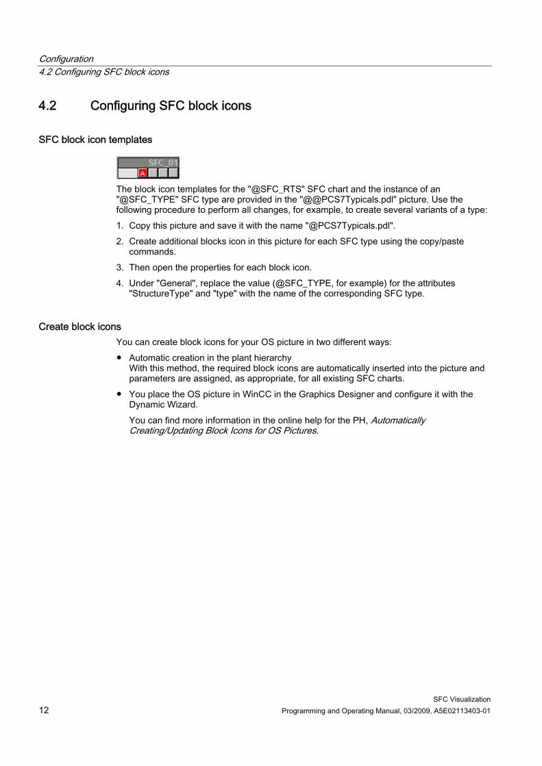
SFC block icon templates
The block icon templates for the "@SFC_RTS" SFC chart and the instance of an "@SFC_TYPE" SFC type are provided in the "@@PCS7Typicals.pdl" picture. Use the following procedure to perform all changes, for example, to create several variants of a type: 1. Copy this picture and save it with the name "@PCS7Typicals.pdl". 2. Create additional blocks icon in this picture for each SFC type using the copy/paste
commands. 3. Then open the properties for each block icon. 4. Under "General", replace the value (@SFC_TYPE, for example) for the attributes
"StructureType" and "type" with the name of the corresponding SFC type.
Create block icons You can create block icons for your OS picture in two different ways: ● Automatic creation in the plant hierarchy
With this method, the required block icons are automatically inserted into the picture and parameters are assigned, as appropriate, for all existing SFC charts.
● You place the OS picture in WinCC in the Graphics Designer and configure it with the Dynamic Wizard. You can find more information in the online help for the PH, Automatically Creating/Updating Block Icons for OS Pictures.
Configuration 4.2 Configuring SFC block icons
SFC Visualization Programming and Operating Manual, 03/2009, A5E02113403-01 13
Procedure in WinCC 1. Copy the required block icon from the template to your current picture. 2. Adapt the "StructureType" and "type" property to the type name (not necessary for the
block icon for SFC chart). 3. Select the block icon and double-click "Connect faceplate to process tag" in the "Default
Dynamics" tab of the "Dynamic Wizard" window. The Dynamic Wizard opens.
4. Click "..." on the "Set Options" page. The "Variables - Project:" opens.
5. In the WinCC variables, open the "List of all variables" and double-click the corresponding variable for the chart or instance in the right window to select it. The dialog box closes; the variable name is entered in the Dynamic Wizard.
6. Click "Next". The next page shows what the wizard is now generating.
7. Click "Finish". The block icon is now configured. You can use it to call the associated faceplate in runtime operation.
Configuration 4.3 Configuring SFC faceplates
SFC Visualization 14 Programming and Operating Manual, 03/2009, A5E02113403-01
4.3 Configuring SFC faceplates
SFC faceplates There are two types of faceplate templates for visualizing the various SFC instances of the SFC types and for visualizing SFC charts in runtime: ● The "@pg_@sfc_rts.pdl" variant is used to visualize SFCs. ● The "@pg_@sfc_type.pdl" variant is used to visualize SFC instances of an SFC type. The
interface elements (setpoints, control strategies, for example) that are configured in the "Characteristics" dialog box are included in this faceplate.
In addition to the display objects (type name/instance name, comment, group display, etc.) that are created with the standard WinCC resources, the faceplates contain an OCX for displaying and manipulating the operating state logic and an OCX (for SFC instance) for displaying and manipulating the setpoints. You also use these OCX in SFC Visualization. The meanings of the elements in all faceplate views are described in: Operating and monitoring SFCs by means of faceplate (Page 26)
Configuration The faceplates are supplied preconfigured and you can customize them individually. You can also create your own faceplates from the templates. However, you use the available OCX for displaying and manipulating the operating state logic and the setpoints (for SFC instance). You can find a detailed description of the configuration of faceplates in the manual PCS 7 Programming Instructions for Blocks.
Additional information You can find more information in the section Adapting Faceplates (Page 15)
Configuration 4.4 Adapting faceplates
SFC Visualization Programming and Operating Manual, 03/2009, A5E02113403-01 15
4.4 Adapting faceplates
Introduction The "Actual Values" (@pg_@sfc_type_actualsp.pdl) and "Prepared Values" (@pg_@sfc_type_prepare.pdl) views are adapted in Graphics Designer.
Procedure 1. Open the "@pg_@sfc_type_actualsp.pdl" or "@pg_@sfc_type_prepare.pdl" picture in
Graphics Designer. 2. Double-click in the OCX area of the picture.
The "Properties of @PCS 7 SFC SP Control" dialog box opens. 3. In the "General" tab, use the '"Actual Values" view enabled' option to specify if the
operator can edit the information in the setpoint column or if it is write-protected. Note: This option can be set both in the properties of the "Actual Values" and "Prepared Values" views. It only affects the "Actual Values" view.
4. In the "Colors" tab, you can change the font and background colors of the respective OCX elements.
Configuration 4.5 Preparing the controls
SFC Visualization 16 Programming and Operating Manual, 03/2009, A5E02113403-01
4.5 Preparing the controls
Introduction You can prepare for the configuration of the controls in order to facilitate insertion of the controls in a graphic display.
Procedure 1. Open the desired picture in Graphics Designer. 2. Switch to the "Controls" tab in the object palette. 3. Select the "Add/Remove" command from the shortcut menu in the Object Palette".
The "Select OCX" dialog box opens. 4. In the list, select:
– PCS 7 SFC Control – PCS 7 SFC MultiChart Control
5. Click "OK" to close the dialog box. The two controls are now in the object palette and can be inserted directly from there into the graphic display using drag-and-drop.
Configuration 4.6 Configuring the "PCS7 SFC Control" status display
SFC Visualization Programming and Operating Manual, 03/2009, A5E02113403-01 17
4.6 Configuring the "PCS7 SFC Control" status display
Introduction The states of an SFC can output to a graphic display by means of an SFC control which is assigned to this chart. This control is also known as the status display (same as the SFC MultiChart Control). You place and configure the status display in a graphic display in the WinCC Graphics Designer.
Placing the PCS 7 SFC Control in the Graphic Display Open the desired graphic display in the Graphics Designer. ● If you have performed the Preparation for the Controls (Page 16), use a drag-and-drop
operation to move the "PCS 7 SFC Control" from the "Controls" object palette to the picture.
● If the controls are not yet in the object palette, proceed as follows:
– Select the entry in the "Smart Objects" tool palette. – Draw a frame in the graphic display for the object to be displayed.
The selection list of all installed "Controls" will be displayed. – Select "PCS 7 SFC Control."
Configure 1. Double-click the SFC Control.
The "Properties" dialog box opens. 2. Open the "General" tab. 3. Specify whether the SFC should be opened as an "Overview" or "Section" (detailed)
display. The respective button in SFC Control will be labeled accordingly.
4. Click "Assign SFC." Another dialog box opens listing all the SFCs on this OS.
5. Select the desired SFC. 6. Close the dialog box with "OK".
Under "Connected SFC:" you can see the current SFC name. When you close the "Properties" dialog box with "OK," the current SFC name is also in the control.
Options in the other tabs: ● You can individually configure the display of the SFC control. ● In the "Colors" tab, you can use the color palette to change the current colors for certain
elements (for example, title bar, window background, etc.).
Note You can also use the Dynamic Wizard to assign parameters for the status display – as in previous versions.
Configuration 4.7 Configuring the "PCS7 SFC MultiChart Control" status display
SFC Visualization 18 Programming and Operating Manual, 03/2009, A5E02113403-01
4.7 Configuring the "PCS7 SFC MultiChart Control" status display
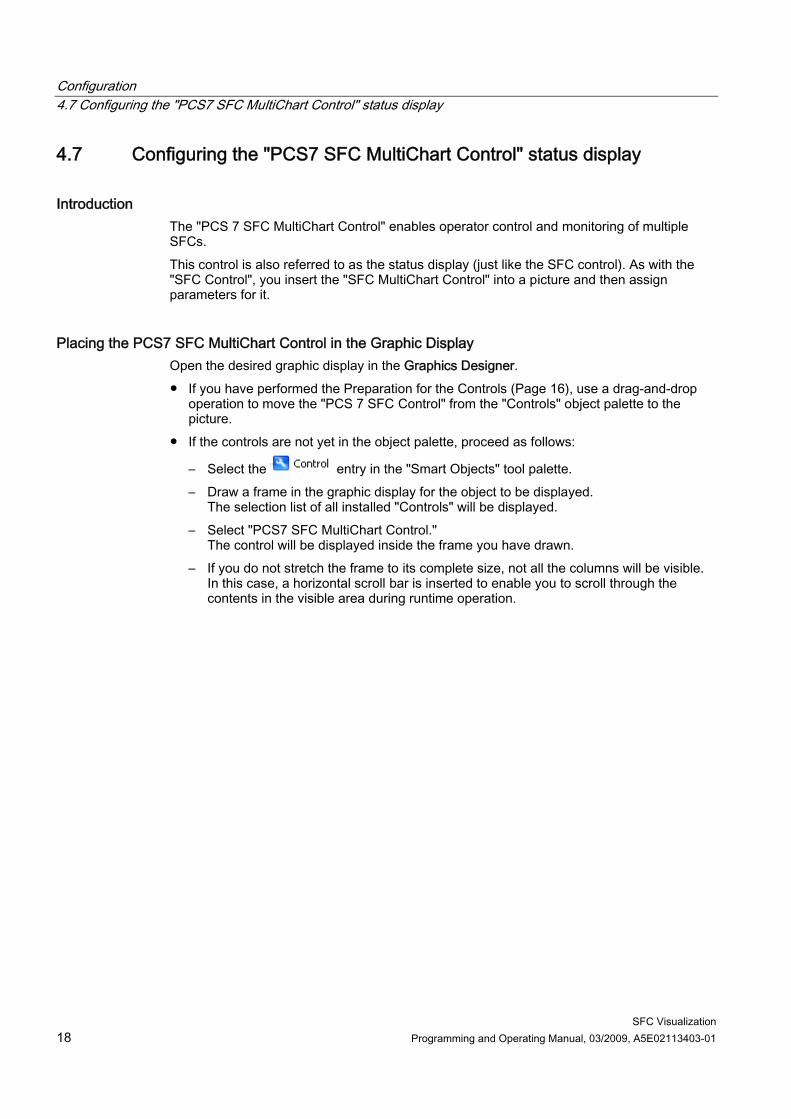
Introduction The "PCS 7 SFC MultiChart Control" enables operator control and monitoring of multiple SFCs. This control is also referred to as the status display (just like the SFC control). As with the "SFC Control", you insert the "SFC MultiChart Control" into a picture and then assign parameters for it.
Placing the PCS7 SFC MultiChart Control in the Graphic Display Open the desired graphic display in the Graphics Designer. ● If you have performed the Preparation for the Controls (Page 16), use a drag-and-drop
operation to move the "PCS 7 SFC Control" from the "Controls" object palette to the picture.
● If the controls are not yet in the object palette, proceed as follows:
– Select the entry in the "Smart Objects" tool palette. – Draw a frame in the graphic display for the object to be displayed.
The selection list of all installed "Controls" will be displayed. – Select "PCS7 SFC MultiChart Control."
The control will be displayed inside the frame you have drawn. – If you do not stretch the frame to its complete size, not all the columns will be visible.
In this case, a horizontal scroll bar is inserted to enable you to scroll through the contents in the visible area during runtime operation.
Configuration 4.7 Configuring the "PCS7 SFC MultiChart Control" status display
SFC Visualization Programming and Operating Manual, 03/2009, A5E02113403-01 19
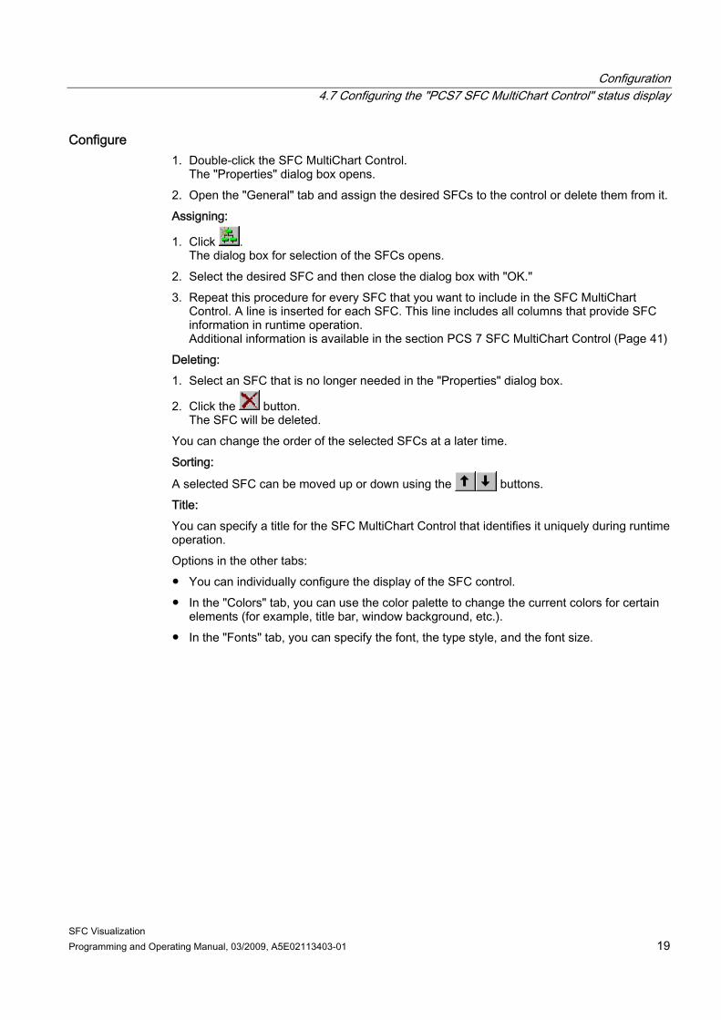
Configure 1. Double-click the SFC MultiChart Control.
The "Properties" dialog box opens. 2. Open the "General" tab and assign the desired SFCs to the control or delete them from it. Assigning:
1. Click . The dialog box for selection of the SFCs opens.
2. Select the desired SFC and then close the dialog box with "OK." 3. Repeat this procedure for every SFC that you want to include in the SFC MultiChart
Control. A line is inserted for each SFC. This line includes all columns that provide SFC information in runtime operation. Additional information is available in the section PCS 7 SFC MultiChart Control (Page 41)
Deleting: 1. Select an SFC that is no longer needed in the "Properties" dialog box.
2. Click the button. The SFC will be deleted.
You can change the order of the selected SFCs at a later time. Sorting:
A selected SFC can be moved up or down using the buttons. Title: You can specify a title for the SFC MultiChart Control that identifies it uniquely during runtime operation. Options in the other tabs: ● You can individually configure the display of the SFC control. ● In the "Colors" tab, you can use the color palette to change the current colors for certain
elements (for example, title bar, window background, etc.). ● In the "Fonts" tab, you can specify the font, the type style, and the font size.
Configuration 4.8 Configuring the SFC button
SFC Visualization 20 Programming and Operating Manual, 03/2009, A5E02113403-01
4.8 Configuring the SFC button
Introduction For selecting an SFC, you can also configure any graphic object of your choice. Such an object serves to represent the SFC chart. Unlike an SFC status display, however, it does not receive any information on the current status of the SFC. Such an object can be a button, for example.
Procedure The procedure is basically the same as that for configuring the SFC control: 1. Select the "Button" object from the "Windows Objects" view and draw a frame in the
graphic display. A dialog box opens.
2. Make the required settings (text input for label, font, operator authorization, etc.). Click "OK" to close the dialog box.
3. Double-click "Configure SFC button" in the Dynamic Wizard. 4. If an instructional page appears, ignore it by clicking "Next". 5. On the next page, select the mouse action for opening the SFC, which you will assign in
the next step. The "SFC Browser" opens.
6. Select the SFC to be associated with the button. 7. In the "Set Option" dialog box, choose the display in which the SFC is to be opened
("Overview" or "Section"). 8. Click "Finish" to complete the configuration.
Configuration 4.9 Configuring the SFC browser selection
SFC Visualization Programming and Operating Manual, 03/2009, A5E02113403-01 21
4.9 Configuring the SFC browser selection
Introduction You place an object in the graphic display in order to call the SFC browser in runtime. Use this browser to select the SFCs.
Procedure 1. In the Graphics Designer object palette, select the desired object and draw a frame in the
graphic display. 2. Double-click "Configure SFC Browser" in the Dynamic Wizard. 3. If an instructional page appears, ignore it by clicking "Next". 4. In the next dialog box, select the mouse action for opening the SFC. 5. Click "Finish" to complete the configuration.
Configuration 4.10 Using functions for user-specific scripts (SFC API Calls)
SFC Visualization 22 Programming and Operating Manual, 03/2009, A5E02113403-01
4.10 Using functions for user-specific scripts (SFC API Calls)
SFC API functions The Graphics Designer contains template scripts for assigning certain actions to objects. SFC Visualization offers many functions. The most important functions are included in these script templates. You can also use the functionality of SFC Visualization in your own scripts. For this purpose, you read in the "sfccli.h" header file. Insert the line ' # include "sfccli.h" ' in the script. The most important functions are described in SFC API Functions (Page 70).
General Information about the Functions ● If a Boolean value is returned, then TRUE = success and FALSE = error. ● Functions that have "LPOHIO_ERRORSTRUCT IpdmError" as a parameter can be called
with "(void*)0". The error is not evaluated in this case. ● If a window handle is needed, specify the window of the "parent" for this new window.
"NULL" is also allowed as the assignment. In this case, the desktop is used as the "parent" of the new window.
Configuration 4.11 OS Server and OS Client
SFC Visualization Programming and Operating Manual, 03/2009, A5E02113403-01 23
4.11 OS Server and OS Client
4.11.1 What you should know about OS Server and OS Client
What is an OS Server? An OS Server is interconnected with the AS. It receives process data, however, it usually does not provide any operating and monitoring functionality within a multi-user system. The OS Server contains all of the configuration data, and you can modify these data here.
What is an OS Client? An OS Client is an operator station (OS) on which you can operate and monitor the process in runtime. A client neither has its own SFCs, nor any process I/O. The Client lets you operate and monitor SFCs on the OS Servers, however, it does not allow their editing.
How do I access OS Server data? Server project data are made known to the client by means of reference lists (packages). The client can access the server data only after the packages have been generated and downloaded. The same applies to SFC Visualization, where only references to the SFCs are exported instead of the actual data. You therefore do not have to recompile and download the packages again after having edited an SFC. You only have to generate and download a new package to the client only if SFCs have been deleted, added or renamed. Additional information is available in the Process Control System PCS 7; Operator Station Configuring Manual.
Configuring SFC Visualization You can configure the visualization and operator controls in WinCC Explorer on the client as described in the "Basic SFC settings" section of this documentation. The basic SFC settings available for the server projects are not relevant to the client. If not configured otherwise, the default settings are activated for the client. In a multi-client project you can place objects for opening SFC charts in graphic displays and interconnect these with SFC charts similar to the server project. You can find information about this in the section Configurations for SFC Visualization (Page 11). You must download the corresponding packages to the client for this.
Configuration 4.11 OS Server and OS Client
SFC Visualization 24 Programming and Operating Manual, 03/2009, A5E02113403-01
Note on server project configurations ● Configurations for SFC visualization in graphic displays (for example, SFC selection
buttons, SFC status display) will also work on the client. ● Server projects can be configured at the client. Information about corresponding
procedures is available in the Process Control System PCS 7; Operator Station Configuring Manual.
Permanent operability for clients SFC Visualization supports "permanent operability" for clients. A preferred server configured on the client is used as the server. This applies regardless of whether the server is the current MASTER or STANDBY. If there is a redundancy failover SFC Visualization reacts in accordance with the behavior defined in WinCC.
SFC Visualization Programming and Operating Manual, 03/2009, A5E02113403-01 25
Operating and monitoring SFCs 55.1 Access control
Access control Operator input is allowed without restriction if no users are configured. The following settings or functions are performed, depending on the logged on user and the authorization levels configured for SFC Visualization: ● Operator input buttons are activated or deactivated. ● Operator input is subject to verification.
This input is either accepted or discarded, depending on the result. The authorization levels set on the Engineering Station are transferred to the OS server (OS > Load target system), where they are used in runtime operation. ● Global and SFC-specific authorization levels can be configured on an OS server.
However, these are overwritten the next time the function OS > Load target system is used. If SFC-specific authorization levels exist on the OS server, these are used at runtime. If no SFC-specific authorization levels are configured, the global authorization levels of the OS server are used.
● On an OS multiclient, only SFC-global authorization levels can be configured. If SFC-specific authorization levels exist on the OS server, these are used at runtime. If no SFC-specific authorization levels are configured, the global authorization levels of the OS multiclient are used.
● An OS Web Server does not have its own authorization levels. The relevant authorization levels are transferred depending on whether it is an OS multiclient or an OS server.
● An OS Web Client does not have its own authorization levels. The authorization levels of the OS Web server are used at runtime.
Note If button or a setpoint is not enabled although the user has the necessary operator authorization, then operation may be disabled on the block (for instance ENSTART = 0).
Operating and monitoring SFCs 5.2 Operating and monitoring the SFC by means of faceplate
SFC Visualization 26 Programming and Operating Manual, 03/2009, A5E02113403-01
5.2 Operating and monitoring the SFC by means of faceplate
Overview You operate the SFC chart and the SFC instance by means of a faceplate. ● The SFC chart faceplate has two views:
– "Standard" view (Page 27) – "Messages" view (Page 28)
● The SFC Instance faceplate has five views: – "Actual Values" view (Page 29) – "Prepared Values" View (Page 34) – "Parameters" view (Page 35) – "Messages" view (Page 36) – "Batch" view (Page 37)
Note You can only ever start an SFC instance in the faceplate in the "Prepared Values" view. This is most important if control strategies or setpoints are being used, because a control strategy and setpoints have to be set prior to starting.
Holding the faceplate In the top left-hand corner above the overview line there is a button that can be used to "pin" the faceplate in order to keep it in place if the focus is changed. The button is visualized as follows:
Unpinned (after the faceplate is called)
Pinned (after the key is pressed) Once pinned, a faceplate will remain pinned until it is closed, i.e., pressing the button again will have no effect.
Note ● When you open the faceplate, the "Prepared Values" view (Idle or MANUAL mode) or the
"Actual Values" view (in all other operating states) is displayed depending on the current operating state of the SFC.
● When a faceplate is open, a change in the operating state does not automatically change the view.
Operating and monitoring SFCs 5.3 SFC chart faceplate, "Standard" view
SFC Visualization Programming and Operating Manual, 03/2009, A5E02113403-01 27
5.3 SFC chart faceplate, "Standard" view
"Standard" view
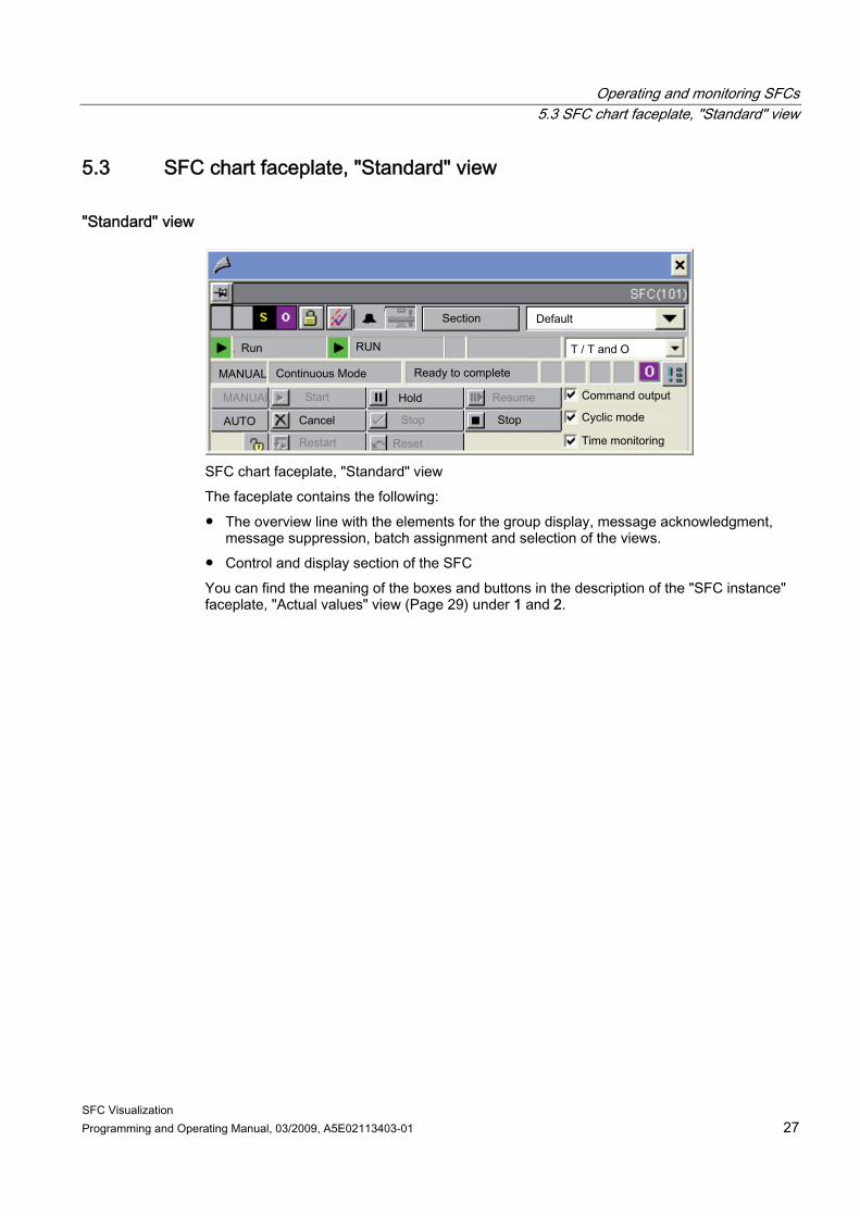
SFC chart faceplate, "Standard" view The faceplate contains the following: ● The overview line with the elements for the group display, message acknowledgment,
message suppression, batch assignment and selection of the views. ● Control and display section of the SFC You can find the meaning of the boxes and buttons in the description of the "SFC instance" faceplate, "Actual values" view (Page 29) under 1 and 2.
Operating and monitoring SFCs 5.4 "SFC Chart" faceplate, "Messages" view
SFC Visualization 28 Programming and Operating Manual, 03/2009, A5E02113403-01
5.4 "SFC Chart" faceplate, "Messages" view
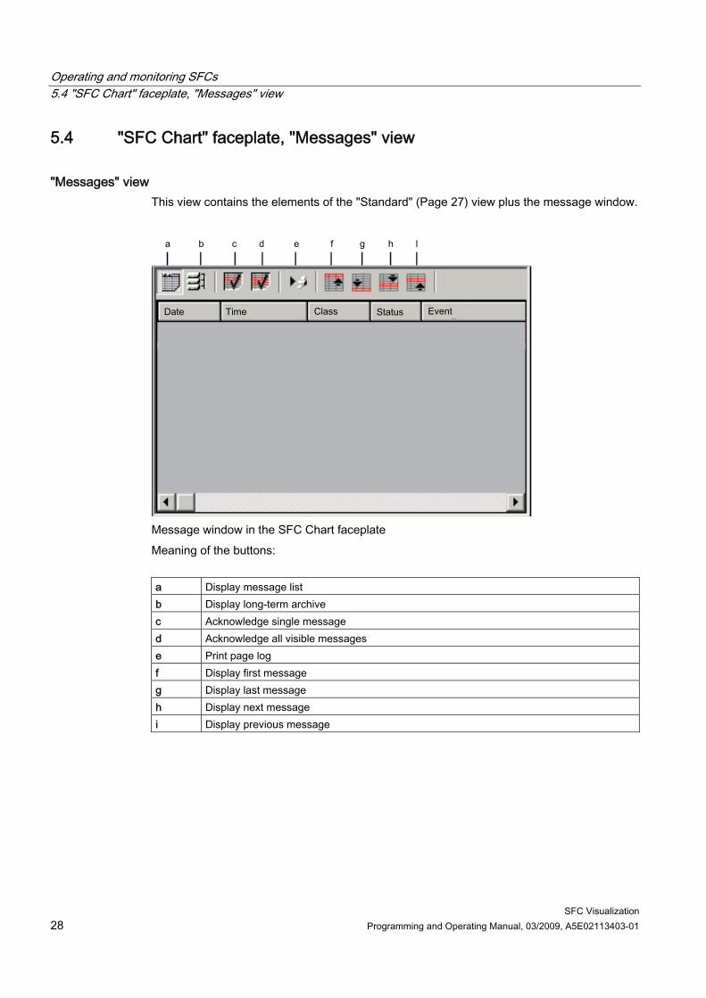
"Messages" view This view contains the elements of the "Standard" (Page 27) view plus the message window.
Message window in the SFC Chart faceplate Meaning of the buttons: a Display message list b Display long-term archive c Acknowledge single message d Acknowledge all visible messages e Print page log f Display first message g Display last message h Display next message i Display previous message
Operating and monitoring SFCs 5.5 "SFC Instance" faceplate, "Actual Values" view
SFC Visualization Programming and Operating Manual, 03/2009, A5E02113403-01 29
5.5 "SFC Instance" faceplate, "Actual Values" view
"Actual Values" view
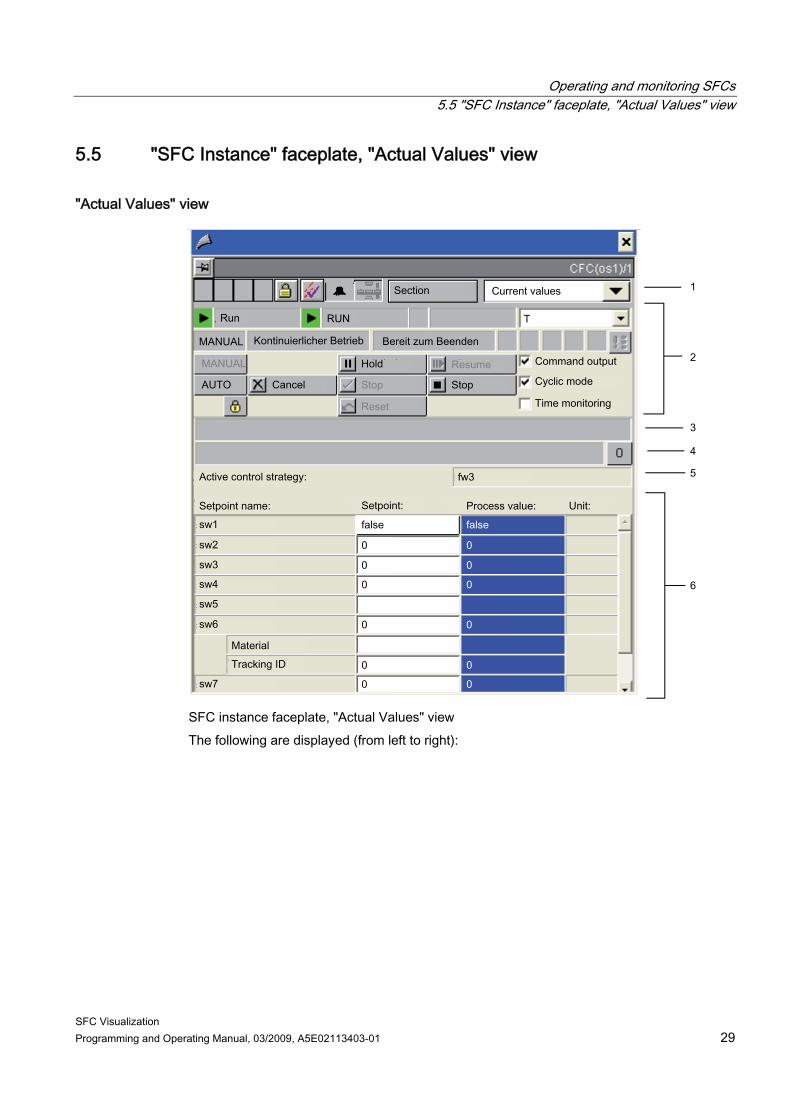
SFC instance faceplate, "Actual Values" view The following are displayed (from left to right):
Operating and monitoring SFCs 5.5 "SFC Instance" faceplate, "Actual Values" view
SFC Visualization 30 Programming and Operating Manual, 03/2009, A5E02113403-01
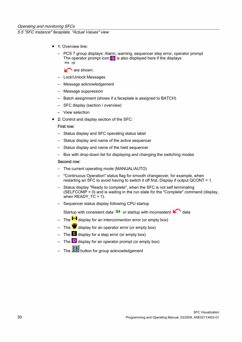
● 1: Overview line: – PCS 7 group displays: Alarm, warning, sequencer step error, operator prompt
The operator prompt icon is also displayed here if the displays or
are shown. – Lock/Unlock Messages – Message acknowledgement – Message suppression – Batch assignment (shows if a faceplate is assigned to BATCH) – SFC display (section / overview) – View selection
● 2: Control and display section of the SFC: First row: – Status display and SFC operating status label – Status display and name of the active sequencer – Status display and name of the held sequencer – Box with drop-down list for displaying and changing the switching modes Second row: – The current operating mode (MANUAL/AUTO) – "Continuous Operation" status flag for smooth changeover, for example, when
restarting an SFC to avoid having to switch it off first. Display if output QCONT = 1. – Status display "Ready to complete", when the SFC is not self terminating
(SELFCOMP = 0) and is waiting in the run state for the "Complete" command (display, when READY_TC = 1).
– Sequencer status display following CPU startup
Startup with consistent data or startup with inconsistent data
– The display for an interconnection error (or empty box)
– The display for an operator error (or empty box) – The display for a step error (or empty box) – The display for an operator prompt (or empty box)
– The button for group acknowledgement
Operating and monitoring SFCs 5.5 "SFC Instance" faceplate, "Actual Values" view
SFC Visualization Programming and Operating Manual, 03/2009, A5E02113403-01 31
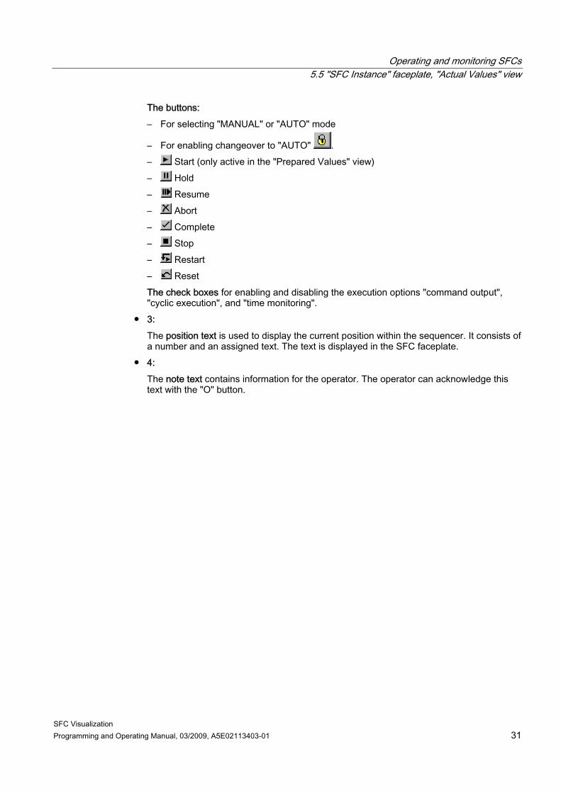
The buttons: – For selecting "MANUAL" or "AUTO" mode
– For enabling changeover to "AUTO" . – Start (only active in the "Prepared Values" view) – Hold – Resume – Abort – Complete – Stop – Restart – Reset The check boxes for enabling and disabling the execution options "command output", "cyclic execution", and "time monitoring".
● 3: The position text is used to display the current position within the sequencer. It consists of a number and an assigned text. The text is displayed in the SFC faceplate.
● 4: The note text contains information for the operator. The operator can acknowledge this text with the "O" button.
Operating and monitoring SFCs 5.5 "SFC Instance" faceplate, "Actual Values" view
SFC Visualization 32 Programming and Operating Manual, 03/2009, A5E02113403-01
● 5: The line shows the active control strategy. The control strategy cannot be changed here. The control strategy can only be selected in the "Prepared Values" view.
● 6: The setpoints and actual values assigned to the selected control strategy are displayed in this table. – Setpoint name
A setpoint can consist of more than one value. In the example picture, the "sw6" setpoint has the additional values "Material" and "Batch ID".
– Setpoint The current setpoints are displayed here. The setpoints can be edited if the "Actual values view enabled" option is selected when configuring the properties of the control. The configured upper and lower limit values are also shown during editing.
Note If a setpoint is changed, the change must be confirmed by pressing the RETURN key (exception: values with the Boolean data type). The system then opens another window, in which the change must be confirmed once more by choosing "OK". If you do not choose "OK", the change is not transferred.
Actual value The values of the actual value output are displayed here.
– Unit The unit labels are displayed here.
Operating and monitoring SFCs 5.6 "SFC Instance" faceplate, "Block contacts" view
SFC Visualization Programming and Operating Manual, 03/2009, A5E02113403-01 33
5.6 "SFC Instance" faceplate, "Block contacts" view
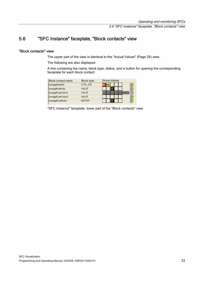
"Block contacts" view The upper part of the view is identical to the "Actual Values" (Page 29) view. The following are also displayed: A line containing the name, block type, status, and a button for opening the corresponding faceplate for each block contact.
"SFC Instance" faceplate, lower part of the "Block contacts" view
Operating and monitoring SFCs 5.7 "SFC Instance" faceplate, "Prepared Values" view
SFC Visualization 34 Programming and Operating Manual, 03/2009, A5E02113403-01
5.7 "SFC Instance" faceplate, "Prepared Values" view
"Prepared Values" view The view is identical to the "Actual Values" (Page 29) view. You can change the control strategy and the setpoints here. The changes made in this view are applied the next time you start the sequencer.
Note You can only ever start an SFC instance in the faceplate in the "Prepared Values" view. This is most important if control strategies or setpoints are being used, because a control strategy and setpoints have to be set prior to starting.
Operating and monitoring SFCs 5.8 "SFC Instance" faceplate, "Parameters" view
SFC Visualization Programming and Operating Manual, 03/2009, A5E02113403-01 35
5.8 "SFC Instance" faceplate, "Parameters" view
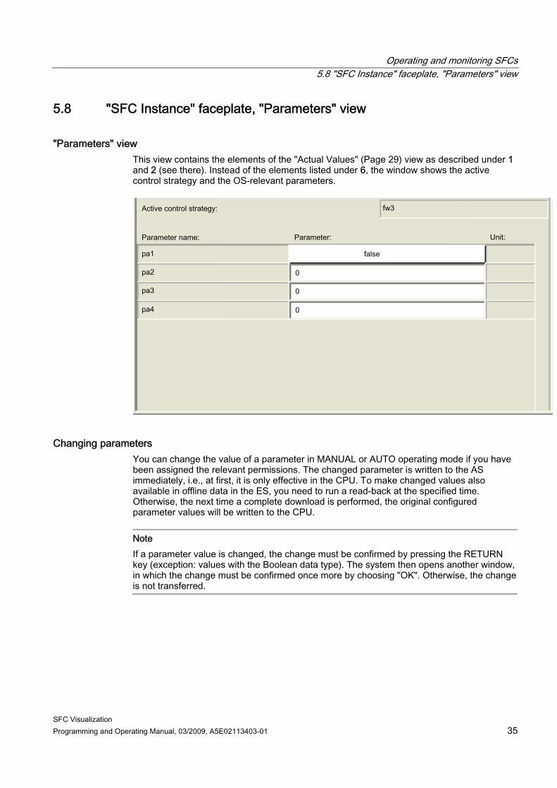
"Parameters" view This view contains the elements of the "Actual Values" (Page 29) view as described under 1 and 2 (see there). Instead of the elements listed under 6, the window shows the active control strategy and the OS-relevant parameters.
Changing parameters You can change the value of a parameter in MANUAL or AUTO operating mode if you have been assigned the relevant permissions. The changed parameter is written to the AS immediately, i.e., at first, it is only effective in the CPU. To make changed values also available in offline data in the ES, you need to run a read-back at the specified time. Otherwise, the next time a complete download is performed, the original configured parameter values will be written to the CPU.
Note If a parameter value is changed, the change must be confirmed by pressing the RETURN key (exception: values with the Boolean data type). The system then opens another window, in which the change must be confirmed once more by choosing "OK". Otherwise, the change is not transferred.
Operating and monitoring SFCs 5.9 "SFC Instance" faceplate, "Messages" view
SFC Visualization 36 Programming and Operating Manual, 03/2009, A5E02113403-01
5.9 "SFC Instance" faceplate, "Messages" view
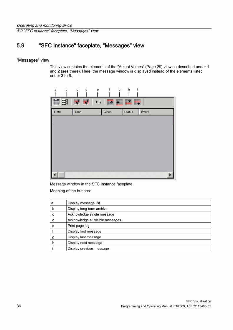
"Messages" view This view contains the elements of the "Actual Values" (Page 29) view as described under 1 and 2 (see there). Here, the message window is displayed instead of the elements listed under 3 to 6.
Message window in the SFC Instance faceplate Meaning of the buttons: a Display message list b Display long-term archive c Acknowledge single message d Acknowledge all visible messages e Print page log f Display first message g Display last message h Display next message i Display previous message
Operating and monitoring SFCs 5.10 "SFC Instance" faceplate, "Batch" view
SFC Visualization Programming and Operating Manual, 03/2009, A5E02113403-01 37
5.10 "SFC Instance" faceplate, "Batch" view
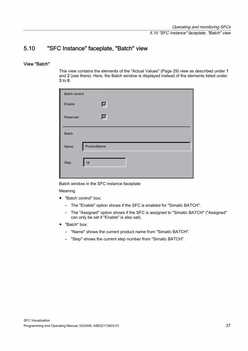
View "Batch" This view contains the elements of the "Actual Values" (Page 29) view as described under 1 and 2 (see there). Here, the Batch window is displayed instead of the elements listed under 3 to 6.
Batch window in the SFC instance faceplate Meaning ● "Batch control" box:
– The "Enable" option shows if the SFC is enabled for "Simatic BATCH". – The "Assigned" option shows if the SFC is assigned to "Simatic BATCH" ("Assigned"
can only be set if "Enable" is also set). ● "Batch" box:
– "Name" shows the current product name from "Simatic BATCH". – "Step" shows the current step number from "Simatic BATCH".
Operating and monitoring SFCs 5.11 Operating and monitoring the SFC by means of SFC status display
SFC Visualization 38 Programming and Operating Manual, 03/2009, A5E02113403-01
5.11 Operating and monitoring the SFC by means of SFC status display
SFC status display You obtain an overview of the SFC status (PCS 7 SFC Control) by selecting a graphic display that contains a status display configured for the SFC. "PCS 7 SFC MultiChart Control" supports monitoring of multiple SFCs and editing of certain parameters. PCS 7 SFC Control (Page 39) PCS 7 SFC MultiChart Control (Page 41)
Operating and monitoring SFCs 5.12 PCS 7 SFC Control
SFC Visualization Programming and Operating Manual, 03/2009, A5E02113403-01 39
5.12 PCS 7 SFC Control
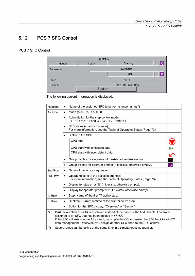
PCS 7 SFC Control
The following current information is displayed: Heading • Name of the assigned SFC (chart or instance name) *)
• Mode (MANUAL / AUTO)
• Abbreviation for the step control mode ("T", "T or O", "T and O", "O", "T / T and O").
• SFC status (chart or instance); For more information, see the Table of Operating States (Page 73).
• Status in the CPU
CPU stop
CPU start with consistent data CPU start with inconsistent data
• Group display for step error (if it exists, otherwise empty).
1st Row
• Group display for operator prompt (if it exists, otherwise empty). 2nd Row • Name of the active sequencer
• Operating state of the active sequencer; For more information, see the Table of Operating States (Page 73).
• Display for step error "S" (if it exists, otherwise empty).
3rd Row
• Display for operator prompt "O" (if it exists, otherwise empty).
4. Row • Step: Name of the first **) active step.
5. Row • Runtime: Current runtime of the first **) active step.
• Button for the SFC display: "Overview" or "Section".
*) If ## Initialization error ## is displayed instead of the name of the text, this SFC control is assigned to an SFC that has been deleted in WinCC. If the SFC still exists in the AS project, recompile the OS to transfer the SFC back to WinCC data management. Otherwise, you assign another SFC chart to the SFC control.
**) Several steps can be active at the same time in a simultaneous sequencer.
Operating and monitoring SFCs 5.12 PCS 7 SFC Control
SFC Visualization 40 Programming and Operating Manual, 03/2009, A5E02113403-01
You change to the detailed view of the SFC by clicking the "Section" button (as configured in this example), or if the "Overview" button is configured, you change to the overview display. If "S" is displayed, the system also opens the "Properties" dialog box for the step. Click on "S" to open the detail display for the SFC and center the active step using the error acknowledgement button. If "O" is displayed, the system also opens the "Properties" dialog box for the transition. Click on "O" to open the detail display for the SFC and center the active transition using the acknowledgement button of the operator prompt.
Operating and monitoring SFCs 5.13 PCS 7 SFC MultiChart Control
SFC Visualization Programming and Operating Manual, 03/2009, A5E02113403-01 41
5.13 PCS 7 SFC MultiChart Control
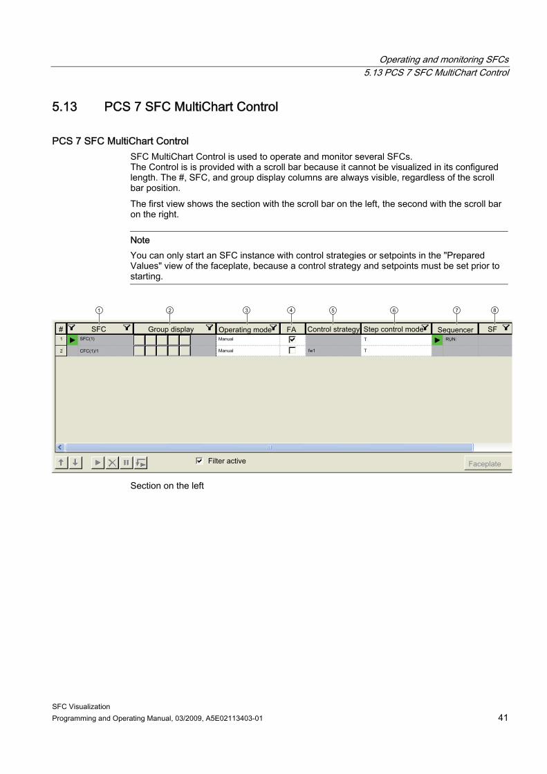
PCS 7 SFC MultiChart Control SFC MultiChart Control is used to operate and monitor several SFCs. The Control is is provided with a scroll bar because it cannot be visualized in its configured length. The #, SFC, and group display columns are always visible, regardless of the scroll bar position. The first view shows the section with the scroll bar on the left, the second with the scroll bar on the right.
Note You can only start an SFC instance with control strategies or setpoints in the "Prepared Values" view of the faceplate, because a control strategy and setpoints must be set prior to starting.
Section on the left
Operating and monitoring SFCs 5.13 PCS 7 SFC MultiChart Control
SFC Visualization 42 Programming and Operating Manual, 03/2009, A5E02113403-01
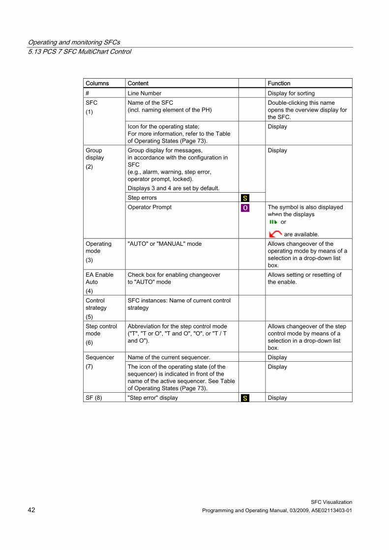
Columns Content Function # Line Number Display for sorting
Name of the SFC (incl. naming element of the PH)
Double-clicking this name opens the overview display for the SFC.
SFC (1)
Icon for the operating state; For more information, refer to the Table of Operating States (Page 73).
Display
Group display for messages, in accordance with the configuration in SFC (e.g., alarm, warning, step error, operator prompt, locked). Displays 3 and 4 are set by default.
Step errors
Display Group display (2)
Operator Prompt The symbol is also displayed when the displays
or
are available. Operating mode (3)
"AUTO" or "MANUAL" mode Allows changeover of the operating mode by means of a selection in a drop-down list box.
EA Enable Auto (4)
Check box for enabling changeover to "AUTO" mode
Allows setting or resetting of the enable.
Control strategy (5)
SFC instances: Name of current control strategy
Step control mode (6)
Abbreviation for the step control mode ("T", "T or O", "T and O", "O", or "T / T and O").
Allows changeover of the step control mode by means of a selection in a drop-down list box.
Name of the current sequencer. Display Sequencer (7) The icon of the operating state (of the
sequencer) is indicated in front of the name of the active sequencer. See Table of Operating States (Page 73).
Display
SF (8) "Step error" display Display
Operating and monitoring SFCs 5.13 PCS 7 SFC MultiChart Control
SFC Visualization Programming and Operating Manual, 03/2009, A5E02113403-01 43
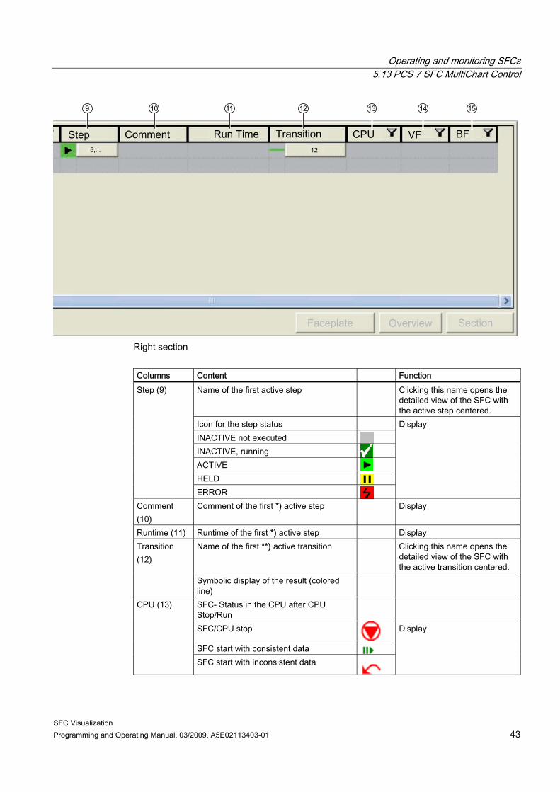
Right section Columns Content Function
Name of the first active step Clicking this name opens the detailed view of the SFC with the active step centered.
Icon for the step status INACTIVE not executed INACTIVE, running ACTIVE HELD
Step (9)
ERROR
Display
Comment (10)
Comment of the first *) active step Display
Runtime (11) Runtime of the first *) active step Display Name of the first **) active transition Clicking this name opens the
detailed view of the SFC with the active transition centered.
Transition (12)
Symbolic display of the result (colored line)
SFC- Status in the CPU after CPU Stop/Run
SFC/CPU stop
SFC start with consistent data
CPU (13)
SFC start with inconsistent data
Display
Operating and monitoring SFCs 5.13 PCS 7 SFC MultiChart Control
SFC Visualization 44 Programming and Operating Manual, 03/2009, A5E02113403-01
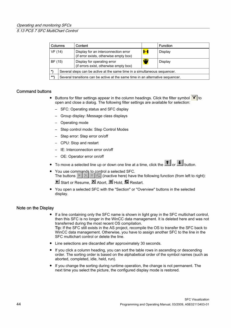
Columns Content Function VF (14) Display for an interconnection error
(if error exists, otherwise empty box) Display
BF (15) Display for operating error (if errors exist, otherwise empty box)
Display
*) Several steps can be active at the same time in a simultaneous sequencer. **) Several transitions can be active at the same time in an alternative sequencer.
Command buttons ● Buttons for filter settings appear in the column headings. Click the filter symbol to
open and close a dialog. The following filter settings are available for selection: – SFC: Operating status and SFC display – Group display: Message class displays – Operating mode – Step control mode: Step Control Modes – Step error: Step error on/off – CPU: Stop and restart – IE: Interconnection error on/off – OE: Operator error on/off
● To move a selected line up or down one line at a time, click the or button. ● You use commands to control a selected SFC.
The buttons (inactive here) have the following function (from left to right): Start or Resume, Abort, Hold, Restart.
● You open a selected SFC with the "Section" or "Overview" buttons in the selected display.
Note on the Display ● If a line containing only the SFC name is shown in light gray in the SFC multichart control,
then this SFC is no longer in the WinCC data management. It is deleted here and was not transferred during the most recent OS compilation. Tip: If the SFC still exists in the AS project, recompile the OS to transfer the SFC back to WinCC data management. Otherwise, you have to assign another SFC to the line in the SFC multichart control or delete the line.
● Line selections are discarded after approximately 30 seconds. ● If you click a column heading, you can sort the table rows in ascending or descending
order. The sorting order is based on the alphabetical order of the symbol names (such as aborted, completed, idle, held, run).
● If you change the sorting during runtime operation, the change is not permanent. The next time you select the picture, the configured display mode is restored.
Operating and monitoring SFCs 5.14 Visualizing the SFC status by means of SFC selection button in the button set or by means of SFC browser selection
SFC Visualization Programming and Operating Manual, 03/2009, A5E02113403-01 45
5.14 Visualizing the SFC status by means of SFC selection button in the button set or by means of SFC browser selection in the picture
Introduction You can also visualize and control the status of an SFC in the runtime system as described below.
Procedure
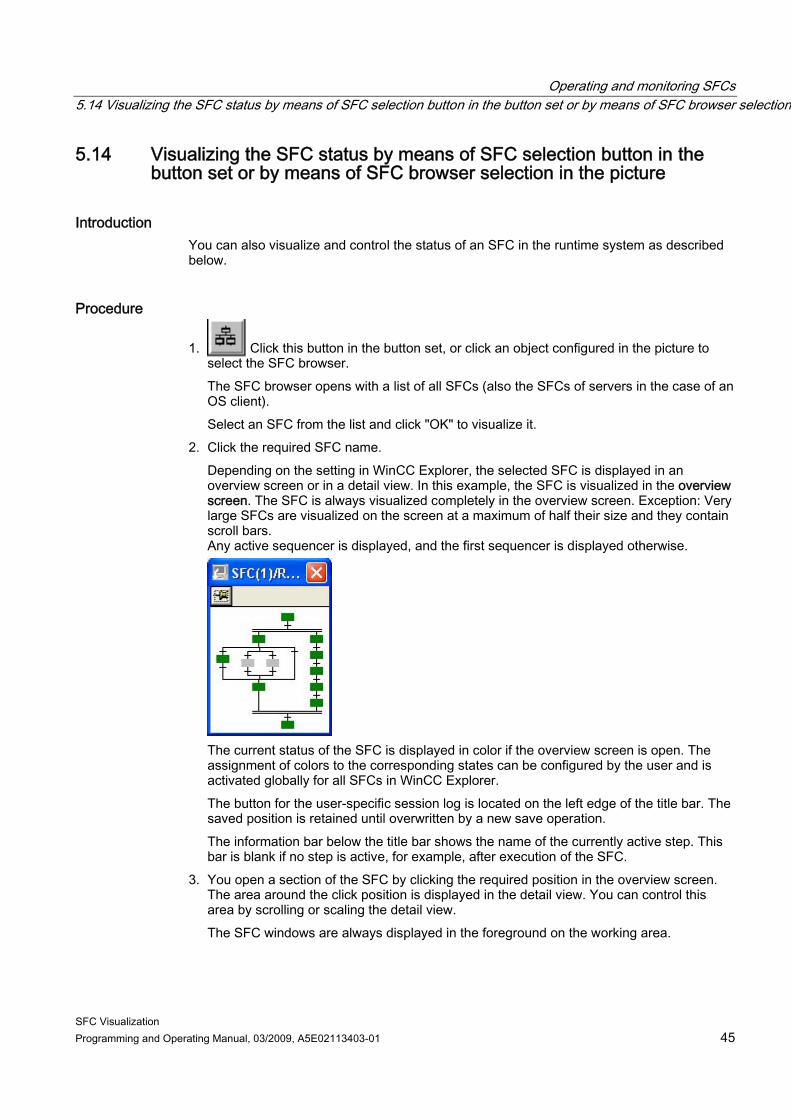
1. Click this button in the button set, or click an object configured in the picture to select the SFC browser. The SFC browser opens with a list of all SFCs (also the SFCs of servers in the case of an OS client). Select an SFC from the list and click "OK" to visualize it.
2. Click the required SFC name. Depending on the setting in WinCC Explorer, the selected SFC is displayed in an overview screen or in a detail view. In this example, the SFC is visualized in the overview screen. The SFC is always visualized completely in the overview screen. Exception: Very large SFCs are visualized on the screen at a maximum of half their size and they contain scroll bars. Any active sequencer is displayed, and the first sequencer is displayed otherwise.
The current status of the SFC is displayed in color if the overview screen is open. The assignment of colors to the corresponding states can be configured by the user and is activated globally for all SFCs in WinCC Explorer. The button for the user-specific session log is located on the left edge of the title bar. The saved position is retained until overwritten by a new save operation. The information bar below the title bar shows the name of the currently active step. This bar is blank if no step is active, for example, after execution of the SFC.
3. You open a section of the SFC by clicking the required position in the overview screen. The area around the click position is displayed in the detail view. You can control this area by scrolling or scaling the detail view. The SFC windows are always displayed in the foreground on the working area.

Operating and monitoring SFCs 5.15 Information and operator input in the detail view
SFC Visualization 46 Programming and Operating Manual, 03/2009, A5E02113403-01
5.15 Information and operator input in the detail view
The detail view
Operating and monitoring SFCs 5.15 Information and operator input in the detail view
SFC Visualization Programming and Operating Manual, 03/2009, A5E02113403-01 47
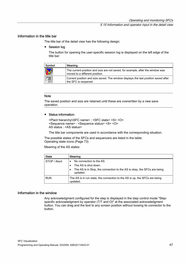
Information in the title bar The title bar of the detail view has the following design: ● Session log
The button for opening the user-specific session log is displayed on the left edge of the title bar:
Symbol Meaning
The current position and size are not saved, for example, after the window was moved to a different position.
Current position and size saved. The window displays the last position saved after the SFC is reopened.
Note The saved position and size are retained until these are overwritten by a new save operation.
● Status information: <Plant hierarchy\\SFC name> : <SFC state> <S> <O> <Sequence name> : <Sequence status> <S> <O> AS status : <AS status> The title bar components are used in accordance with the corresponding situation.
The possible states of the SFCs and sequencers are listed in the table: Operating state icons (Page 73) Meaning of the AS states: State Meaning STOP / Abort • No connection to the AS.
• The AS is shut down. • The AS is in Stop, the connection to the AS is okay, the SFCs are being
updated.
RUN The AS is in run state, the connection to the AS is up, the SFCs are being updated.
Information in the window Any acknowledgment configured for the step is displayed in the step control mode "Step-specific acknowledgment by operator (T/T and O)" at the associated acknowledgment button. You can drag and the text to any screen position without loosing its connector to the button.
Operating and monitoring SFCs 5.15 Information and operator input in the detail view
SFC Visualization 48 Programming and Operating Manual, 03/2009, A5E02113403-01
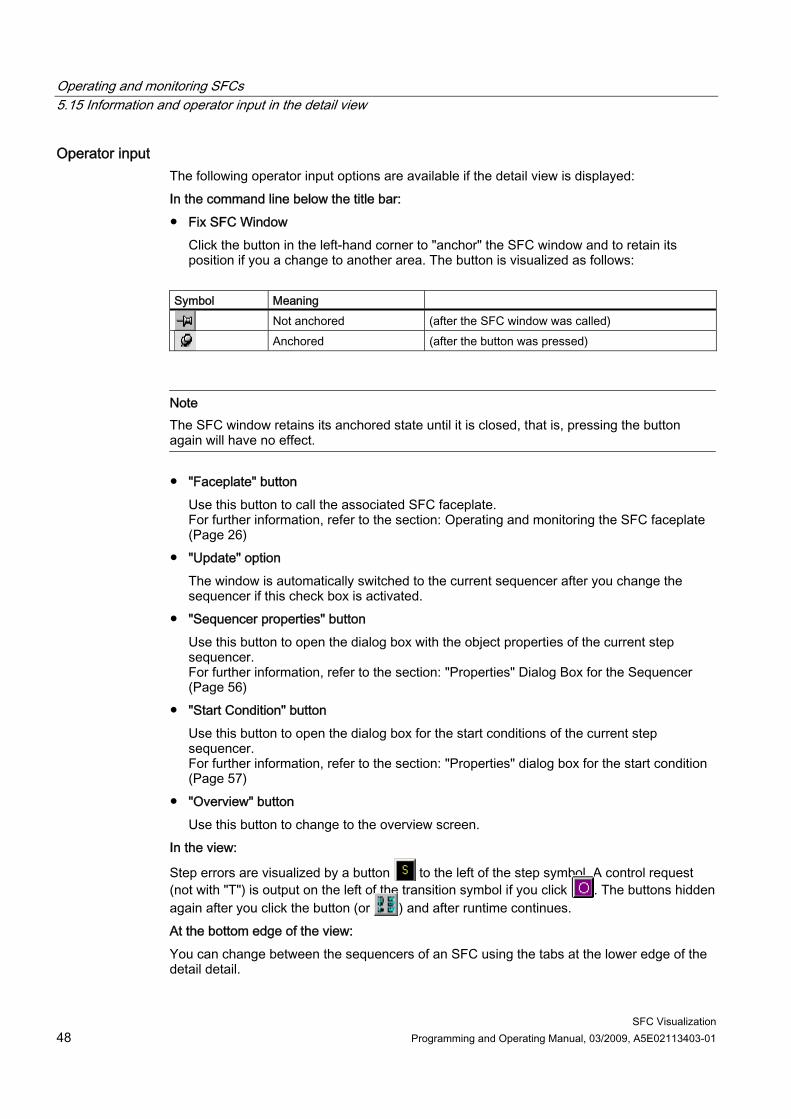
Operator input The following operator input options are available if the detail view is displayed: In the command line below the title bar: ● Fix SFC Window
Click the button in the left-hand corner to "anchor" the SFC window and to retain its position if you a change to another area. The button is visualized as follows:
Symbol Meaning
Not anchored (after the SFC window was called)
Anchored (after the button was pressed)
Note The SFC window retains its anchored state until it is closed, that is, pressing the button again will have no effect.
● "Faceplate" button Use this button to call the associated SFC faceplate. For further information, refer to the section: Operating and monitoring the SFC faceplate (Page 26)
● "Update" option The window is automatically switched to the current sequencer after you change the sequencer if this check box is activated.
● "Sequencer properties" button Use this button to open the dialog box with the object properties of the current step sequencer. For further information, refer to the section: "Properties" Dialog Box for the Sequencer (Page 56)
● "Start Condition" button Use this button to open the dialog box for the start conditions of the current step sequencer. For further information, refer to the section: "Properties" dialog box for the start condition (Page 57)
● "Overview" button Use this button to change to the overview screen.
In the view:
Step errors are visualized by a button to the left of the step symbol. A control request (not with "T") is output on the left of the transition symbol if you click . The buttons hidden again after you click the button (or ) and after runtime continues. At the bottom edge of the view: You can change between the sequencers of an SFC using the tabs at the lower edge of the detail detail.

Operating and monitoring SFCs 5.15 Information and operator input in the detail view
SFC Visualization Programming and Operating Manual, 03/2009, A5E02113403-01 49
In the control and display area: Setting the operating mode (Page 50) Setting the operating mode and acknowledgment (Page 51) Setting the step control mode (Page 52) Setting the sequence options (Page 53) Acknowledging control requests and step errors (Page 54) A description of the views is available in the section "SFC Instance" faceplate, "Actual Values" view (Page 29).
Operating and monitoring SFCs 5.16 Setting the operating mode
SFC Visualization 50 Programming and Operating Manual, 03/2009, A5E02113403-01
5.16 Setting the operating mode
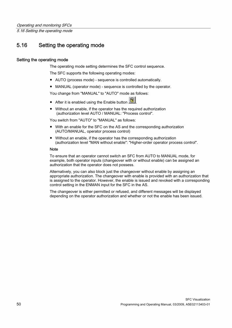
Setting the operating mode The operating mode setting determines the SFC control sequence. The SFC supports the following operating modes: ● AUTO (process mode) - sequence is controlled automatically. ● MANUAL (operator mode) - sequence is controlled by the operator. You change from "MANUAL" to "AUTO" mode as follows:
● After it is enabled using the Enable button . ● Without an enable, if the operator has the required authorization
(authorization level AUTO / MANUAL: "Process control". You switch from "AUTO" to "MANUAL" as follows: ● With an enable for the SFC on the AS and the corresponding authorization
(AUTO/MANUAL, operator process control) ● Without an enable, if the operator has the corresponding authorization
(authorization level "MAN without enable": "Higher-order operator process control". Note To ensure that an operator cannot switch an SFC from AUTO to MANUAL mode, for example, both operator inputs (changeover with or without enable) can be assigned an authorization that the operator does not possess. Alternatively, you can also block just the changeover without enable by assigning an appropriate authorization. The changeover with enable is provided with an authorization that is assigned to the operator. However, the enable is issued and revoked with a corresponding control setting in the ENMAN input for the SFC in the AS. The changeover is either permitted or refused, and different messages will be displayed depending on the operator authorization and whether or not the enable has been issued.
Operating and monitoring SFCs 5.17 Setting the operating state
SFC Visualization Programming and Operating Manual, 03/2009, A5E02113403-01 51
5.17 Setting the operating state
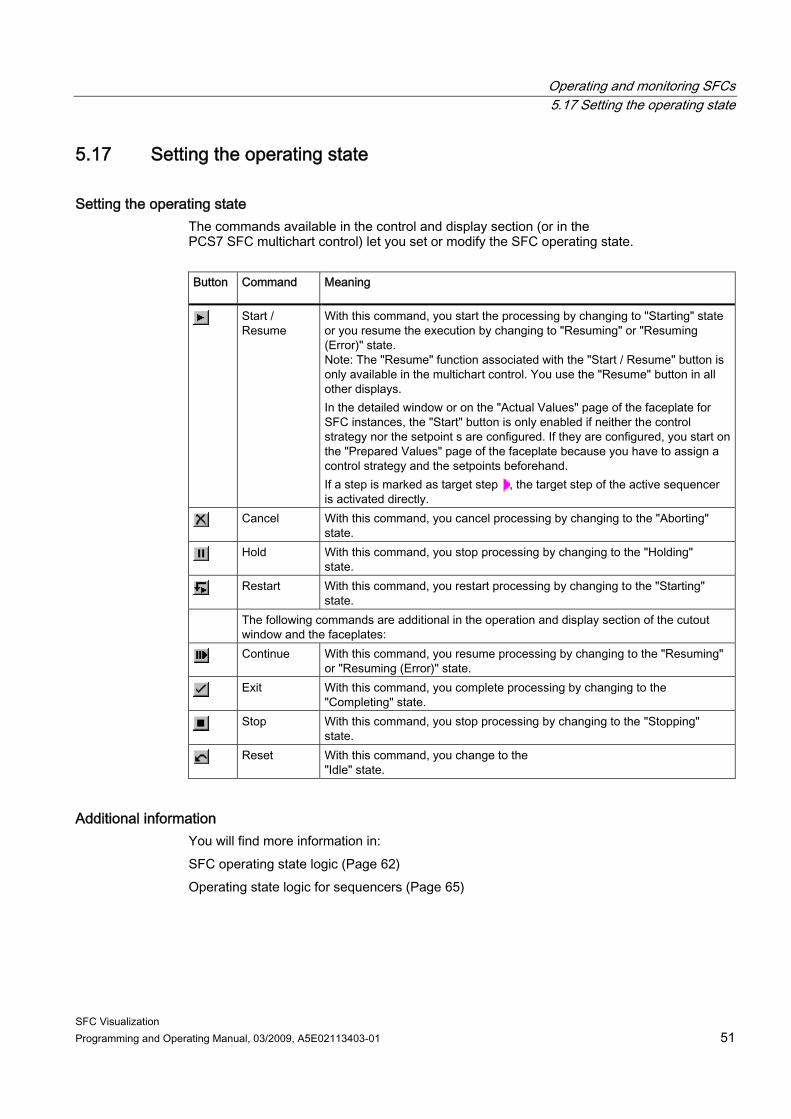
Setting the operating state The commands available in the control and display section (or in the PCS7 SFC multichart control) let you set or modify the SFC operating state. Button
Command Meaning
Start / Resume
With this command, you start the processing by changing to "Starting" state or you resume the execution by changing to "Resuming" or "Resuming (Error)" state. Note: The "Resume" function associated with the "Start / Resume" button is only available in the multichart control. You use the "Resume" button in all other displays. In the detailed window or on the "Actual Values" page of the faceplate for SFC instances, the "Start" button is only enabled if neither the control strategy nor the setpoint s are configured. If they are configured, you start on the "Prepared Values" page of the faceplate because you have to assign a control strategy and the setpoints beforehand. If a step is marked as target step , the target step of the active sequencer is activated directly.
Cancel With this command, you cancel processing by changing to the "Aborting" state.
Hold With this command, you stop processing by changing to the "Holding" state.
Restart With this command, you restart processing by changing to the "Starting" state.
The following commands are additional in the operation and display section of the cutout window and the faceplates:
Continue With this command, you resume processing by changing to the "Resuming" or "Resuming (Error)" state.
Exit With this command, you complete processing by changing to the "Completing" state.
Stop With this command, you stop processing by changing to the "Stopping" state.
Reset With this command, you change to the "Idle" state.
Additional information You will find more information in: SFC operating state logic (Page 62) Operating state logic for sequencers (Page 65)
Operating and monitoring SFCs 5.18 Setting step control mode
SFC Visualization 52 Programming and Operating Manual, 03/2009, A5E02113403-01
5.18 Setting step control mode
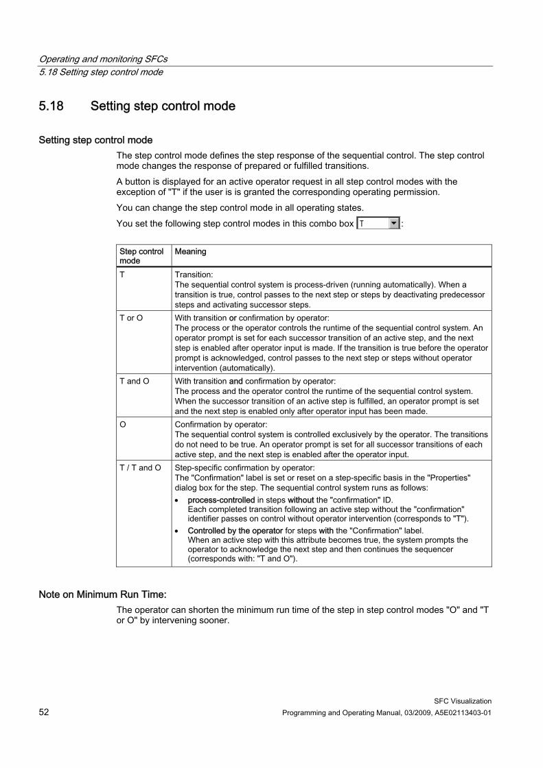
Setting step control mode The step control mode defines the step response of the sequential control. The step control mode changes the response of prepared or fulfilled transitions. A button is displayed for an active operator request in all step control modes with the exception of "T" if the user is is granted the corresponding operating permission. You can change the step control mode in all operating states. You set the following step control modes in this combo box : Step controlmode
Meaning
T Transition: The sequential control system is process-driven (running automatically). When a transition is true, control passes to the next step or steps by deactivating predecessor steps and activating successor steps.
T or O With transition or confirmation by operator: The process or the operator controls the runtime of the sequential control system. An operator prompt is set for each successor transition of an active step, and the next step is enabled after operator input is made. If the transition is true before the operator prompt is acknowledged, control passes to the next step or steps without operator intervention (automatically).
T and O With transition and confirmation by operator: The process and the operator control the runtime of the sequential control system. When the successor transition of an active step is fulfilled, an operator prompt is set and the next step is enabled only after operator input has been made.
O Confirmation by operator: The sequential control system is controlled exclusively by the operator. The transitions do not need to be true. An operator prompt is set for all successor transitions of each active step, and the next step is enabled after the operator input.
T / T and O Step-specific confirmation by operator: The "Confirmation" label is set or reset on a step-specific basis in the "Properties" dialog box for the step. The sequential control system runs as follows: • process-controlled in steps without the "confirmation" ID.
Each completed transition following an active step without the "confirmation" identifier passes on control without operator intervention (corresponds to "T").
• Controlled by the operator for steps with the "Confirmation" label. When an active step with this attribute becomes true, the system prompts the operator to acknowledge the next step and then continues the sequencer (corresponds with: "T and O").
Note on Minimum Run Time: The operator can shorten the minimum run time of the step in step control modes "O" and "T or O" by intervening sooner.
Operating and monitoring SFCs 5.19 Setting the sequence options
SFC Visualization Programming and Operating Manual, 03/2009, A5E02113403-01 53
5.19 Setting the sequence options
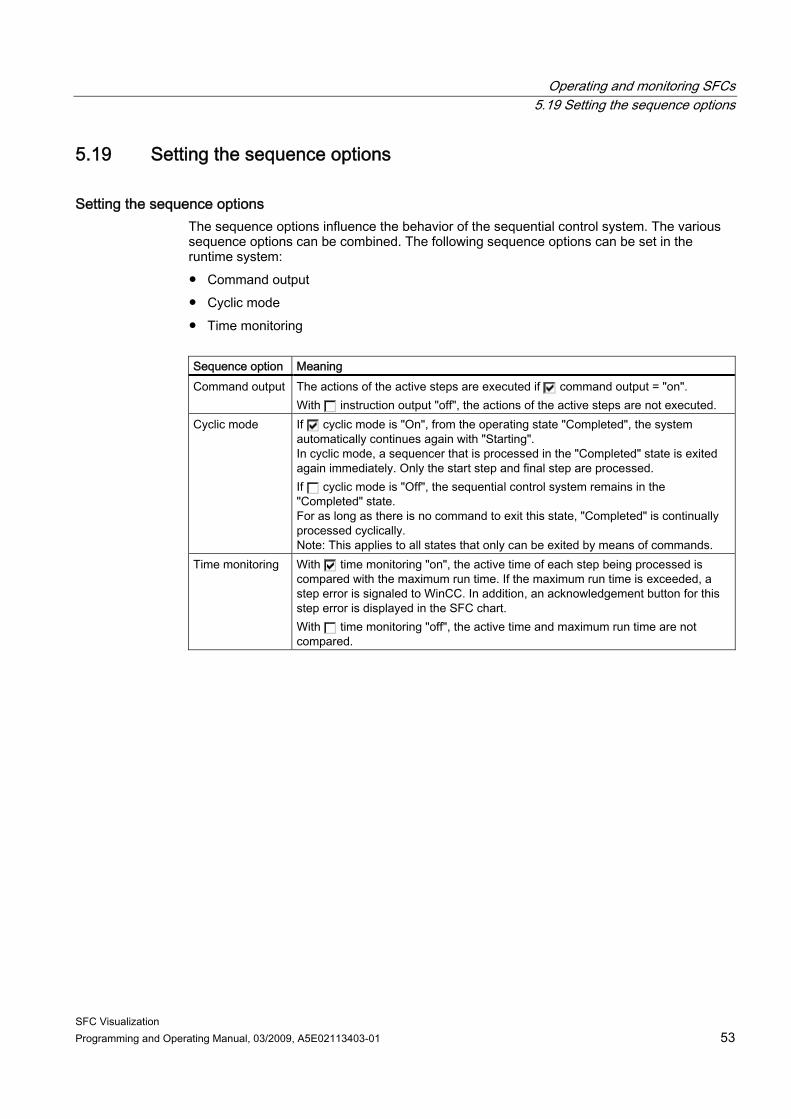
Setting the sequence options The sequence options influence the behavior of the sequential control system. The various sequence options can be combined. The following sequence options can be set in the runtime system: ● Command output ● Cyclic mode ● Time monitoring Sequence option Meaning Command output The actions of the active steps are executed if command output = "on".
With instruction output "off", the actions of the active steps are not executed. Cyclic mode If cyclic mode is "On", from the operating state "Completed", the system
automatically continues again with "Starting". In cyclic mode, a sequencer that is processed in the "Completed" state is exited again immediately. Only the start step and final step are processed. If cyclic mode is "Off", the sequential control system remains in the "Completed" state. For as long as there is no command to exit this state, "Completed" is continually processed cyclically. Note: This applies to all states that only can be exited by means of commands.
Time monitoring With time monitoring "on", the active time of each step being processed is compared with the maximum run time. If the maximum run time is exceeded, a step error is signaled to WinCC. In addition, an acknowledgement button for this step error is displayed in the SFC chart. With time monitoring "off", the active time and maximum run time are not compared.
Operating and monitoring SFCs 5.20 Acknowledging operator requests and step errors
SFC Visualization 54 Programming and Operating Manual, 03/2009, A5E02113403-01
5.20 Acknowledging operator requests and step errors
Acknowledging operator requests and step errors The group acknowledgement button can be used to to acknowledge all active operator requests and step errors in a single pass (using the "S" and "O" buttons for steps and transitions, respectively).
Note In case of a step runtime error, the step is returned to the state which it had before the error occurred (active = "green", for example) after the error has been acknowledged.
Operating and monitoring SFCs 5.21 "Properties" dialog boxes
SFC Visualization Programming and Operating Manual, 03/2009, A5E02113403-01 55
5.21 "Properties" dialog boxes
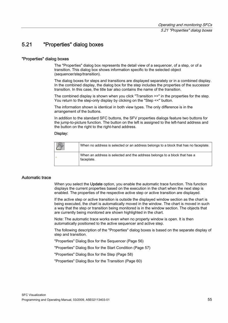
"Properties" dialog boxes The "Properties" dialog box represents the detail view of a sequencer, of a step, or of a transition. This dialog box shows information specific to the selected object (sequencer/step/transition). The dialog boxes for steps and transitions are displayed separately or in a combined display. In the combined display, the dialog box for the step includes the properties of the successor transition. In this case, the title bar also contains the name of the transition. The combined display is shown when you click "Transition >>" in the properties for the step. You return to the step-only display by clicking on the "Step <<" button. The information shown is identical in both view types. The only difference is in the arrangement of the buttons. In addition to the standard SFC buttons, the SFV properties dialogs feature two buttons for the jump-to-picture function. The button on the left is assigned to the left-hand address and the button on the right to the right-hand address. Display:
When no address is selected or an address belongs to a block that has no faceplate.
When an address is selected and the address belongs to a block that has a faceplate.
Automatic trace When you select the Update option, you enable the automatic trace function. This function displays the current properties based on the execution in the chart when the next step is enabled. The properties of the respective active step or active transition are displayed. If the active step or active transition is outside the displayed window section as the chart is being executed, the chart is automatically moved in the window. The chart is moved in such a way that the step or transition being monitored is in the window section. The objects that are currently being monitored are shown highlighted in the chart. Note: The automatic trace works even when no property window is open. It is then automatically positioned to the active sequencer and active step. The following description of the "Properties" dialog boxes is based on the separate display of step and transition. "Properties" Dialog Box for the Sequencer (Page 56) "Properties" Dialog Box for the Start Condition (Page 57) "Properties" Dialog Box for the Step (Page 58) "Properties" Dialog Box for the Transition (Page 60)
Operating and monitoring SFCs 5.22 "Properties" Dialog Box for the Sequencer
SFC Visualization 56 Programming and Operating Manual, 03/2009, A5E02113403-01
5.22 "Properties" Dialog Box for the Sequencer
"Properties" Dialog Box for the Sequencer Select the detail view for the SFC in which you want to display the sequencer "Properties" dialog box. Click "Sequencer Properties" in the operator input section to open the dialog box.
Note You can open a separate dialog box for the start conditions using the "Start Condition" (Page 57) button.
"General" tab: In this tab, you see the following: ● Name of the current sequencer
The box is framed; the frame color indicates the result/state of the transition and is continuously updated.
● Comment of the sequencer ● Priority of the sequencer
The priority decides which sequencer of an SFC is started when the start conditions of several sequencers are met simultaneously.
Note If sequencers with identical start conditions also have the same priority, the sequencer furthest left in the chart will be started first.
"Preprocessing"/"Postprocessing" Tab: In this tab, you see the actions for preprocessing or postprocessing the current sequencer. These actions are executed as follows during cyclic execution of the SFC: ● Before the execution of the sequencers (preprocessing) ● After the execution of the sequencers (postprocessing)

Operating and monitoring SFCs 5.23 "Properties" dialog box of the start condition
SFC Visualization Programming and Operating Manual, 03/2009, A5E02113403-01 57
5.23 "Properties" dialog box of the start condition
"Properties" dialog box of the start condition This dialog box shows the start conditions of the sequencer. The values and conditions of the sequencer are visualized similar to a transition. Additional information is available in the section: "Properties" Dialog Box for the Transition (Page 60)
Operating and monitoring SFCs 5.24 "Properties" Dialog Box for the Step
SFC Visualization 58 Programming and Operating Manual, 03/2009, A5E02113403-01
5.24 "Properties" Dialog Box for the Step
Procedure Select the detail view for the SFC in which you want to display a step "Properties" dialog box. Click the required step to open the dialog box.
"General" tab The runtimes, the "Confirmation" option, the comment and the step status are deactivated in the "General" tab. If no values were configured for the runtimes (time = 0), the respective fields show "- - -". The step state is displayed as text in the title bar and indicated by the corresponding icon to the left of the comment box in the dialog box. State Meaning Icon
normal Icon with target step
INACTIVE, do not run
The step was not being processed previously Not applicable
INACTIVE, run
This step is no longer being processed
ACTIVE The step is being processed. HOLD The step has been held. ERROR The step is in error state
(timeout).
"Initialization", "Processing", "Termination" tabs This tab shows the configured assignments for the individual actions of the step.
Operating and monitoring SFCs 5.24 "Properties" Dialog Box for the Step
SFC Visualization Programming and Operating Manual, 03/2009, A5E02113403-01 59
Operator Inputs in the "Properties" Dialog Box for the Step Operations you can execute in the dialog box: ● Closing the dialog box using the "Close" button ● Acknowledging a step error with the "S" button ● Selecting the previous or next active step with the "S <-" / "-> S" buttons ● Displaying the properties of the successor transition with the "Transition >>" button ● Option: Set / reset "Target step".
If you set the “Target step” option, the current step is selected as the target step. The selection is made to the left of the step). You cannot set the target step when the sequencer is in "Active" state. This means the following: – The next time you start, the inactive sequencer starts at the selected target step
instead of the initial step. – The next time you press the "Resume" button, the "held" sequencer resumes at the
target step after the interrupted steps have been processed properly. The target step remains selected until the next time you start or resume. The selection is cleared if you restart the CPU or change from "MANUAL" to "AUTO" operating mode. Note You can select multiple steps as the target step (in simultaneous sequencers, for example). You are responsible for selecting a suitable target step. Blockades or endless loops in the execution prevent efficient processing. If you use "programmed target steps", the target steps specified by the operator are deleted in the respective sequencers.
● Option: "Update" set / reset. This switches automatic tracing on or off.
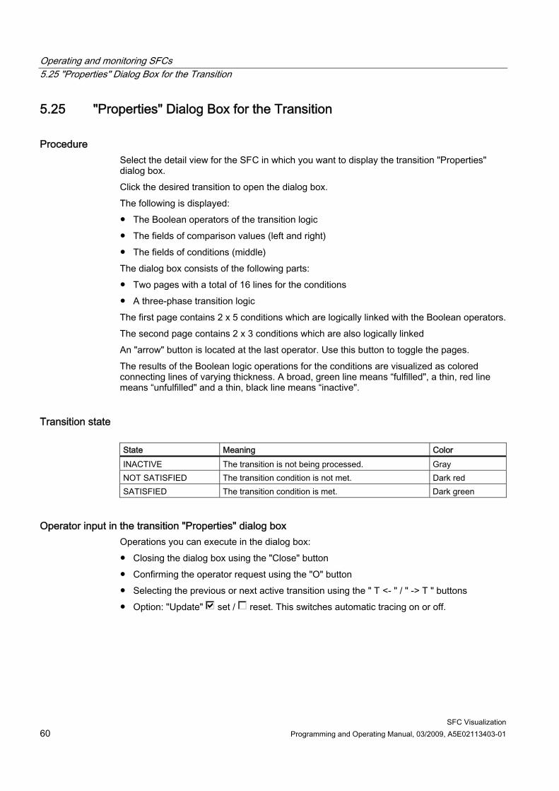
Operating and monitoring SFCs 5.25 "Properties" Dialog Box for the Transition
SFC Visualization 60 Programming and Operating Manual, 03/2009, A5E02113403-01
5.25 "Properties" Dialog Box for the Transition
Procedure Select the detail view for the SFC in which you want to display the transition "Properties" dialog box. Click the desired transition to open the dialog box. The following is displayed: ● The Boolean operators of the transition logic ● The fields of comparison values (left and right) ● The fields of conditions (middle) The dialog box consists of the following parts: ● Two pages with a total of 16 lines for the conditions ● A three-phase transition logic The first page contains 2 x 5 conditions which are logically linked with the Boolean operators. The second page contains 2 x 3 conditions which are also logically linked An "arrow" button is located at the last operator. Use this button to toggle the pages. The results of the Boolean logic operations for the conditions are visualized as colored connecting lines of varying thickness. A broad, green line means “fulfilled", a thin, red line means “unfulfilled" and a thin, black line means “inactive".
Transition state State Meaning Color INACTIVE The transition is not being processed. Gray NOT SATISFIED The transition condition is not met. Dark red SATISFIED The transition condition is met. Dark green
Operator input in the transition "Properties" dialog box Operations you can execute in the dialog box: ● Closing the dialog box using the "Close" button ● Confirming the operator request using the "O" button ● Selecting the previous or next active transition using the " T <- " / " -> T " buttons ● Option: "Update" set / reset. This switches automatic tracing on or off.
Operating and monitoring SFCs 5.26 Messages
SFC Visualization Programming and Operating Manual, 03/2009, A5E02113403-01 61
5.26 Messages
General The following messages are generated during execution of an SFC in the AS: ● Operator requests for transitions ● Step errors ● Status messages relating to the SFC status Only the step error messages require acknowledgment.
Generation of process messages The messages are generated generically. In addition to the messages, specific mechanisms are stored which allow direct access to the picture the message pertains to. The corresponding SFC faceplate will be opened if the block list does not contain a picture. If you insert an SFC status display in a graphic display, the messages of the associated SFC are entered in the hierarchy of the group display.
Process messages in the runtime system The WinCC message system archives and displays the transition and step error messages for operator requests. The message system allows you to open the detail view of the associated SFC for an SFC message and the "Properties" dialog box for the relevant step and transition (button: "Loop In Alarm").
Operating messages in the runtime system If you are controlling the process of an SFC a message is generated for each action and entered into the operation list.
Operating and monitoring SFCs 5.27 Operating state logic
SFC Visualization 62 Programming and Operating Manual, 03/2009, A5E02113403-01
5.27 Operating state logic
5.27.1 Operating state logic for SFC (SFC OSL)
Introduction A change of the current operating state of the SFC OSL can be triggered by the following events: ● Commands (Start, Resume, Hold, etc.) in "MANUAL" or "AUTO" mode ● External signals (inputs of the SFC, commands from another SFC, etc.) ● Internal signals (commands from user-specific sequencers, from test mode or SFC
Visualization) ● Implicit status change
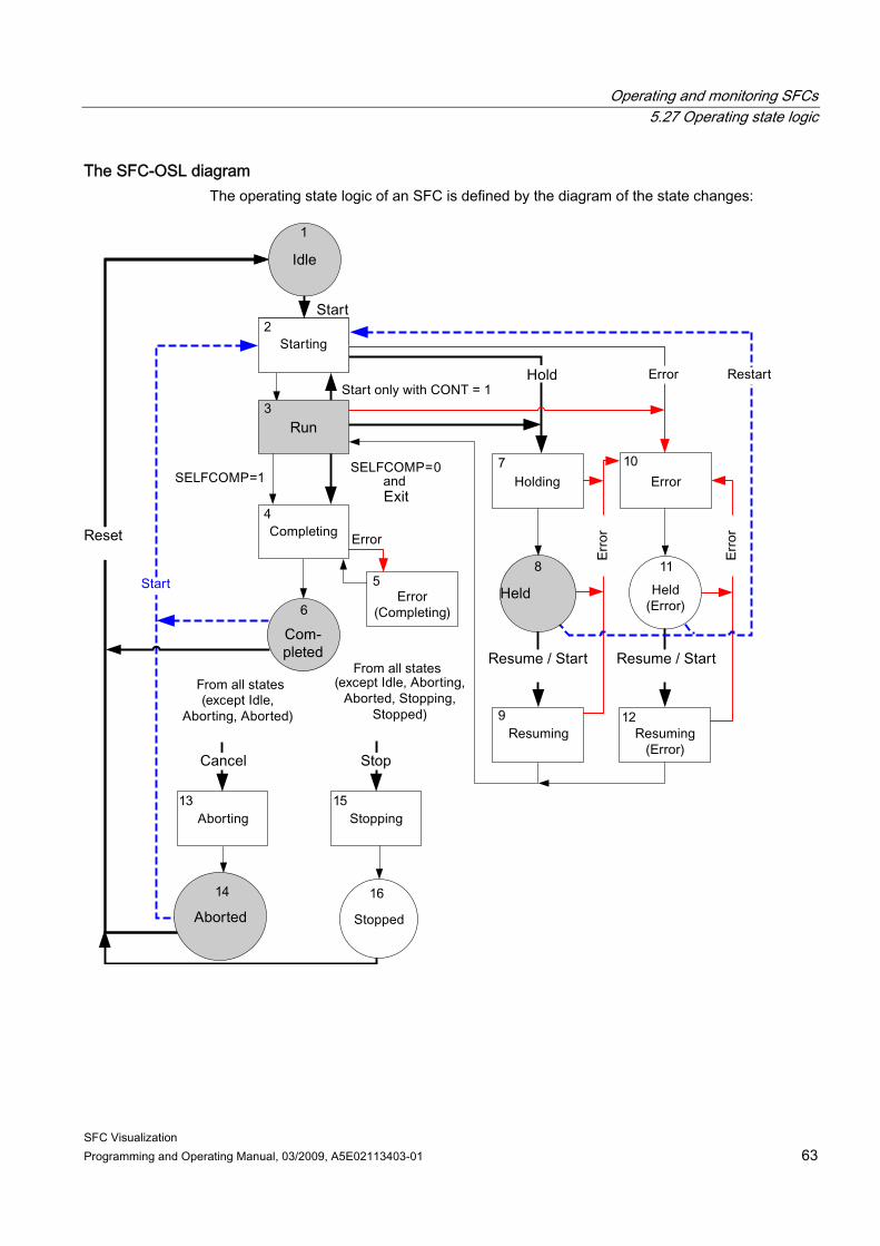
Operating and monitoring SFCs 5.27 Operating state logic
SFC Visualization Programming and Operating Manual, 03/2009, A5E02113403-01 63
The SFC-OSL diagram The operating state logic of an SFC is defined by the diagram of the state changes:
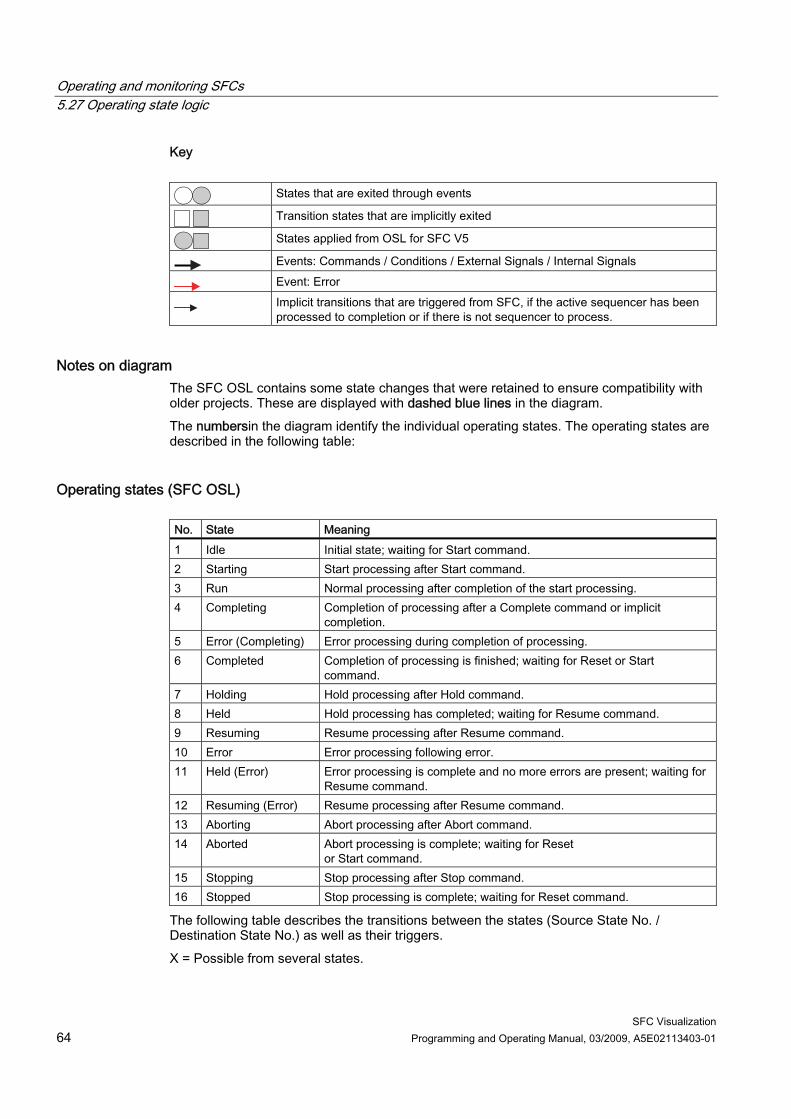
Operating and monitoring SFCs 5.27 Operating state logic
SFC Visualization 64 Programming and Operating Manual, 03/2009, A5E02113403-01
Key
States that are exited through events
Transition states that are implicitly exited
States applied from OSL for SFC V5
Events: Commands / Conditions / External Signals / Internal Signals
Event: Error
Implicit transitions that are triggered from SFC, if the active sequencer has been processed to completion or if there is not sequencer to process.
Notes on diagram The SFC OSL contains some state changes that were retained to ensure compatibility with older projects. These are displayed with dashed blue lines in the diagram. The numbersin the diagram identify the individual operating states. The operating states are described in the following table:
Operating states (SFC OSL) No. State Meaning 1 Idle Initial state; waiting for Start command. 2 Starting Start processing after Start command. 3 Run Normal processing after completion of the start processing. 4 Completing Completion of processing after a Complete command or implicit
completion. 5 Error (Completing) Error processing during completion of processing. 6 Completed Completion of processing is finished; waiting for Reset or Start
command. 7 Holding Hold processing after Hold command. 8 Held Hold processing has completed; waiting for Resume command. 9 Resuming Resume processing after Resume command. 10 Error Error processing following error. 11 Held (Error) Error processing is complete and no more errors are present; waiting for
Resume command. 12 Resuming (Error) Resume processing after Resume command. 13 Aborting Abort processing after Abort command. 14 Aborted Abort processing is complete; waiting for Reset
or Start command. 15 Stopping Stop processing after Stop command. 16 Stopped Stop processing is complete; waiting for Reset command.
The following table describes the transitions between the states (Source State No. / Destination State No.) as well as their triggers. X = Possible from several states.
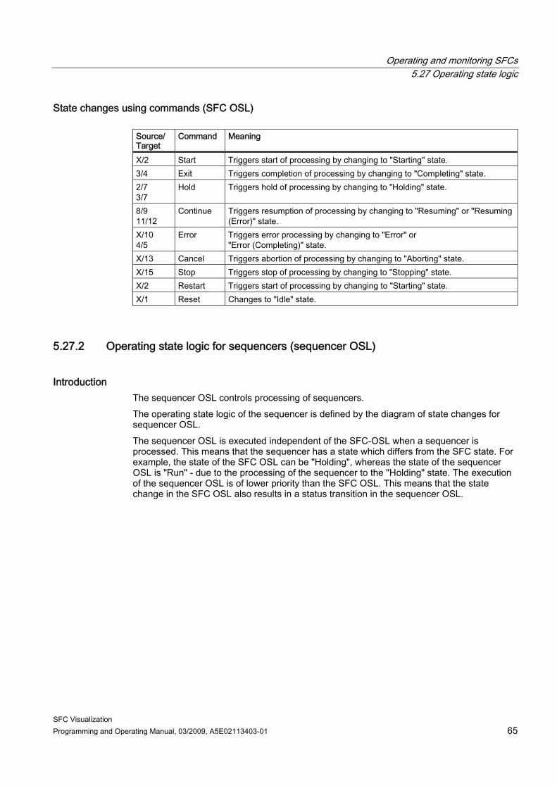
Operating and monitoring SFCs 5.27 Operating state logic
SFC Visualization Programming and Operating Manual, 03/2009, A5E02113403-01 65
State changes using commands (SFC OSL) Source/ Target
Command Meaning
X/2 Start Triggers start of processing by changing to "Starting" state. 3/4 Exit Triggers completion of processing by changing to "Completing" state. 2/7 3/7
Hold Triggers hold of processing by changing to "Holding" state.
8/9 11/12
Continue Triggers resumption of processing by changing to "Resuming" or "Resuming (Error)" state.
X/10 4/5
Error Triggers error processing by changing to "Error" or "Error (Completing)" state.
X/13 Cancel Triggers abortion of processing by changing to "Aborting" state. X/15 Stop Triggers stop of processing by changing to "Stopping" state. X/2 Restart Triggers start of processing by changing to "Starting" state. X/1 Reset Changes to "Idle" state.
5.27.2 Operating state logic for sequencers (sequencer OSL)
Introduction The sequencer OSL controls processing of sequencers. The operating state logic of the sequencer is defined by the diagram of state changes for sequencer OSL. The sequencer OSL is executed independent of the SFC-OSL when a sequencer is processed. This means that the sequencer has a state which differs from the SFC state. For example, the state of the SFC OSL can be "Holding", whereas the state of the sequencer OSL is "Run" - due to the processing of the sequencer to the "Holding" state. The execution of the sequencer OSL is of lower priority than the SFC OSL. This means that the state change in the SFC OSL also results in a status transition in the sequencer OSL.
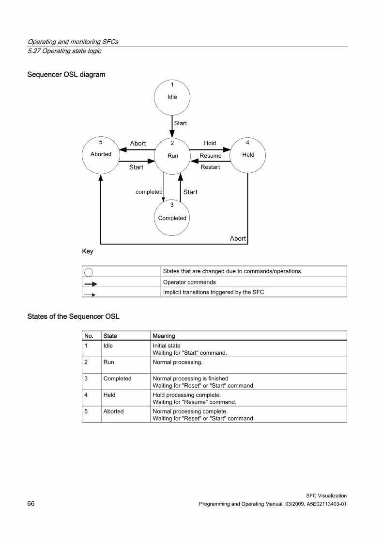
Operating and monitoring SFCs 5.27 Operating state logic
SFC Visualization 66 Programming and Operating Manual, 03/2009, A5E02113403-01
Sequencer OSL diagram
Key
States that are changed due to commands/operations
Operator commands
Implicit transitions triggered by the SFC
States of the Sequencer OSL No. State Meaning 1 Idle Initial state
Waiting for "Start" command. 2 Run Normal processing.
3 Completed Normal processing is finished
Waiting for "Reset" or "Start" command. 4 Held Hold processing complete.
Waiting for "Resume" command. 5 Aborted Normal processing complete.
Waiting for "Reset" or "Start" command.
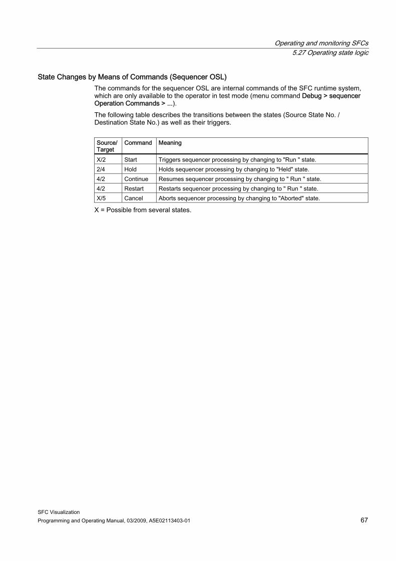
Operating and monitoring SFCs 5.27 Operating state logic
SFC Visualization Programming and Operating Manual, 03/2009, A5E02113403-01 67
State Changes by Means of Commands (Sequencer OSL) The commands for the sequencer OSL are internal commands of the SFC runtime system, which are only available to the operator in test mode (menu command Debug > sequencer Operation Commands > ...). The following table describes the transitions between the states (Source State No. / Destination State No.) as well as their triggers. Source/Target
Command Meaning
X/2 Start Triggers sequencer processing by changing to "Run " state. 2/4 Hold Holds sequencer processing by changing to "Held" state. 4/2 Continue Resumes sequencer processing by changing to " Run " state. 4/2 Restart Restarts sequencer processing by changing to " Run " state. X/5 Cancel Aborts sequencer processing by changing to "Aborted" state.
X = Possible from several states.
Operating and monitoring SFCs 5.28 Operating and monitoring using the Web Client
SFC Visualization 68 Programming and Operating Manual, 03/2009, A5E02113403-01
5.28 Operating and monitoring using the Web Client
5.28.1 Running SFC Visualization on the Web Client
Introduction The SFC visualization on the Web Client in first restricted in V7.0 to the operation of SFC block icons, SFC faceplates and SFC controls. Additional restriction: The "Section" button is not available for the faceplates.
Requirements for using the SFC block icons and SFC faceplates on the Web Client Web Server: ● SFC Visualization is installed on the Web server ● The Web Navigator > Web Configurator command has been selected in the shortcut
menu of the Web Navigator node of WinCC Explorer on the Web server Web Client: ● The relevant plug-ins are installed for SFC Visualization
– WinCC Basic Process Control – WinCC Advanced Process Control – PCS 7 Faceplates – SIMATIC ES Common Services – SIMATIC SFC Common Displays – SIMATIC SFC Visualization
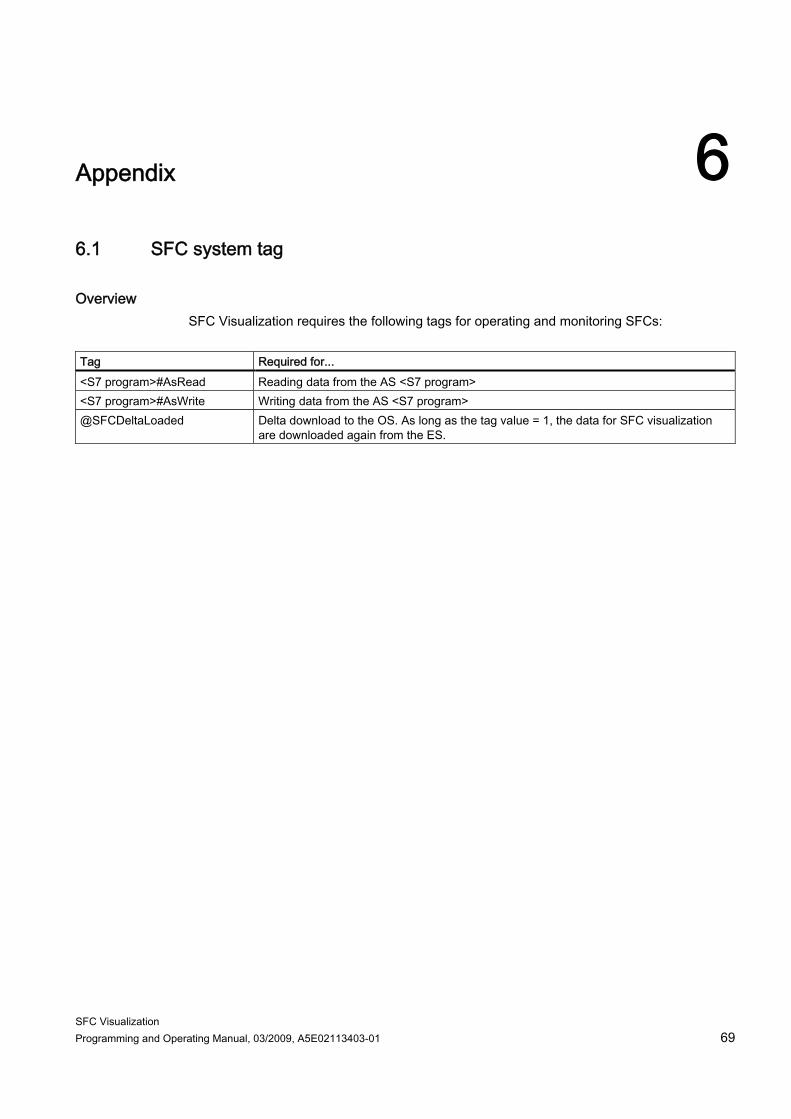
SFC Visualization Programming and Operating Manual, 03/2009, A5E02113403-01 69
Appendix 66.1 SFC system tag
Overview SFC Visualization requires the following tags for operating and monitoring SFCs:
Tag Required for... <S7 program>#AsRead Reading data from the AS <S7 program> <S7 program>#AsWrite Writing data from the AS <S7 program> @SFCDeltaLoaded Delta download to the OS. As long as the tag value = 1, the data for SFC visualization
are downloaded again from the ES.
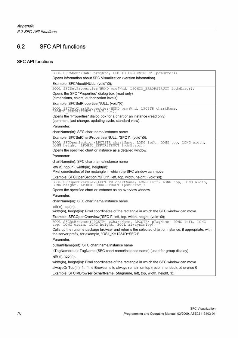
Appendix 6.2 SFC API functions
SFC Visualization 70 Programming and Operating Manual, 03/2009, A5E02113403-01
6.2 SFC API functions
SFC API functions BOOL SFCAbout(HWND projWnd, LPOHIO_ERRORSTRUCT lpdmError); Opens information about SFC Visualization (version information). Example: SFCAbout(NULL, (void*)0); BOOL SFCSetProperties(HWND projWnd, LPOHIO_ERRORSTRUCT lpdmError); Opens the SFC "Properties" dialog box (read only) (dimensions, colors, authorization levels). Example: SFCSetProperties(NULL, (void*)0); BOOL SFCSetChartProperties(HWND projWnd, LPCSTR chartName, LPOHIO_ERRORSTRUCT lpdmError); Opens the "Properties" dialog box for a chart or an instance (read only) (comment, last change, updating cycle, standard view). Parameter: chartName(in): SFC chart name/instance name Example: SFCSetChartProperties(NULL, "SFC1", (void*)0); BOOL SFCOpenSection(LPCTSTR chartName, LONG left, LONG top, LONG width, LONG height, LPOHIO_ERRORSTRUCT lpdmError); Opens the specified chart or instance as a detailed window. Parameter: chartName(in): SFC chart name/instance name left(in), top(in), width(in), height(in): Pixel coordinates of the rectangle in which the SFC window can move Example: SFCOpenSection("SFC1", left, top, width, height, (void*)0); BOOL SFCOpenOverview(LPCTSTR chartName, LONG left, LONG top, LONG width, LONG height, LPOHIO_ERRORSTRUCT lpdmError); Opens the specified chart or instance as an overview window. Parameter: chartName(in): SFC chart name/instance name left(in), top(in), width(in), height(in): Pixel coordinates of the rectangle in which the SFC window can move Example: SFCOpenOverview("SFC1", left, top, width, height, (void*)0); BOOL SFCRtBrowser(LPCSTR* pChartName, LPCSTR* pTagName, LONG left, LONG top, LONG width, LONG height, BOOL alwaysOnTop); Calls up the runtime package browser and returns the selected chart or instance, if appropriate, with the server prefix, for example, "OS1_KH1234D::SFC1" Parameter: pChartName(out): SFC chart name/instance name pTagName(out): TagName (SFC chart name/instance name) (used for group display) left(in), top(in), width(in), height(in): Pixel coordinates of the rectangle in which the SFC window can move alwaysOnTop(in): 1, if the Browser is to always remain on top (recommended), otherwise 0 Example: SFCRtBrowser(&chartName, &tagname, left, top, width, height, 1);
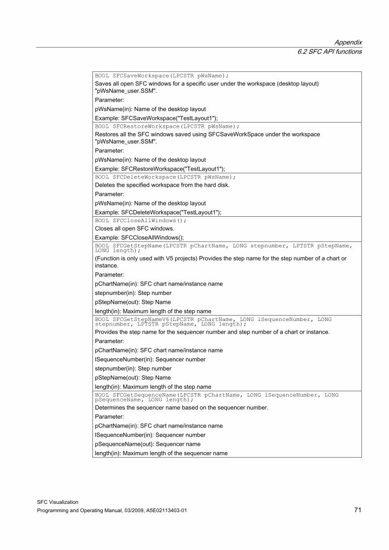
Appendix 6.2 SFC API functions
SFC Visualization Programming and Operating Manual, 03/2009, A5E02113403-01 71
BOOL SFCSaveWorkspace(LPCSTR pWsName); Saves all open SFC windows for a specific user under the workspace (desktop layout) "pWsName_user.SSM". Parameter: pWsName(in): Name of the desktop layout Example: SFCSaveWorkspace("TestLayout1"); BOOL SFCRestoreWorkspace(LPCSTR pWsName); Restores all the SFC windows saved using SFCSaveWorkSpace under the workspace "pWsName_user.SSM". Parameter: pWsName(in): Name of the desktop layout Example: SFCRestoreWorkspace("TestLayout1"); BOOL SFCDeleteWorkspace(LPCSTR pWsName); Deletes the specified workspace from the hard disk. Parameter: pWsName(in): Name of the desktop layout Example: SFCDeleteWorkspace("TestLayout1"); BOOL SFCCloseAllWindows(); Closes all open SFC windows. Example: SFCCloseAllWindows(); BOOL SFCGetStepName(LPCSTR pChartName, LONG stepnumber, LPTSTR pStepName, LONG length); (Function is only used with V5 projects) Provides the step name for the step number of a chart or instance. Parameter: pChartName(in): SFC chart name/instance name stepnumber(in): Step number pStepName(out): Step Name length(in): Maximum length of the step name BOOL SFCGetStepNameV6(LPCSTR pChartName, LONG lSequenceNumber, LONG stepnumber, LPTSTR pStepName, LONG length); Provides the step name for the sequencer number and step number of a chart or instance. Parameter: pChartName(in): SFC chart name/instance name lSequenceNumber(in): Sequencer number stepnumber(in): Step number pStepName(out): Step Name length(in): Maximum length of the step name BOOL SFCGetSequenceName(LPCSTR pChartName, LONG lSequenceNumber, LONG pSequenceName, LONG length); Determines the sequencer name based on the sequencer number. Parameter: pChartName(in): SFC chart name/instance name lSequenceNumber(in): Sequencer number pSequenceName(out): Sequencer name length(in): Maximum length of the sequencer name
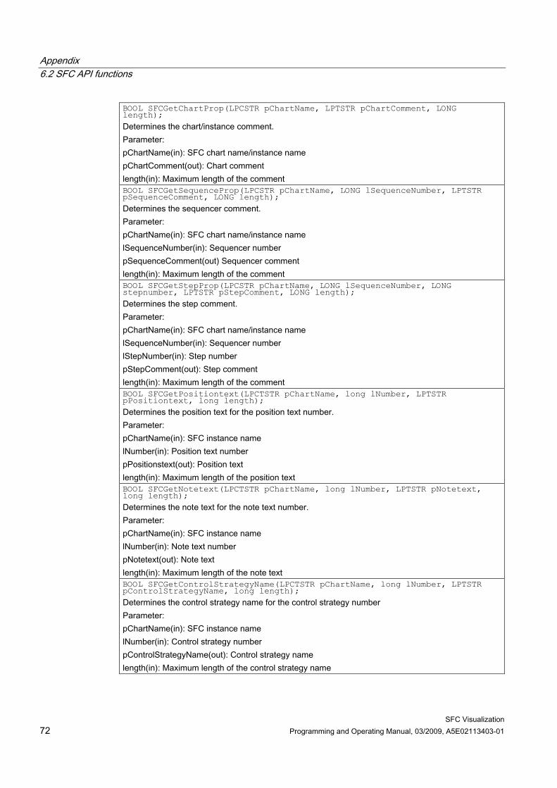
Appendix 6.2 SFC API functions
SFC Visualization 72 Programming and Operating Manual, 03/2009, A5E02113403-01
BOOL SFCGetChartProp(LPCSTR pChartName, LPTSTR pChartComment, LONG length); Determines the chart/instance comment. Parameter: pChartName(in): SFC chart name/instance name pChartComment(out): Chart comment length(in): Maximum length of the comment BOOL SFCGetSequenceProp(LPCSTR pChartName, LONG lSequenceNumber, LPTSTR pSequenceComment, LONG length); Determines the sequencer comment. Parameter: pChartName(in): SFC chart name/instance name lSequenceNumber(in): Sequencer number pSequenceComment(out) Sequencer comment length(in): Maximum length of the comment BOOL SFCGetStepProp(LPCSTR pChartName, LONG lSequenceNumber, LONG stepnumber, LPTSTR pStepComment, LONG length); Determines the step comment. Parameter: pChartName(in): SFC chart name/instance name lSequenceNumber(in): Sequencer number lStepNumber(in): Step number pStepComment(out): Step comment length(in): Maximum length of the comment BOOL SFCGetPositiontext(LPCTSTR pChartName, long lNumber, LPTSTR pPositiontext, long length); Determines the position text for the position text number. Parameter: pChartName(in): SFC instance name lNumber(in): Position text number pPositionstext(out): Position text length(in): Maximum length of the position text BOOL SFCGetNotetext(LPCTSTR pChartName, long lNumber, LPTSTR pNotetext, long length); Determines the note text for the note text number. Parameter: pChartName(in): SFC instance name lNumber(in): Note text number pNotetext(out): Note text length(in): Maximum length of the note text BOOL SFCGetControlStrategyName(LPCTSTR pChartName, long lNumber, LPTSTR pControlStrategyName, long length); Determines the control strategy name for the control strategy number Parameter: pChartName(in): SFC instance name lNumber(in): Control strategy number pControlStrategyName(out): Control strategy name length(in): Maximum length of the control strategy name
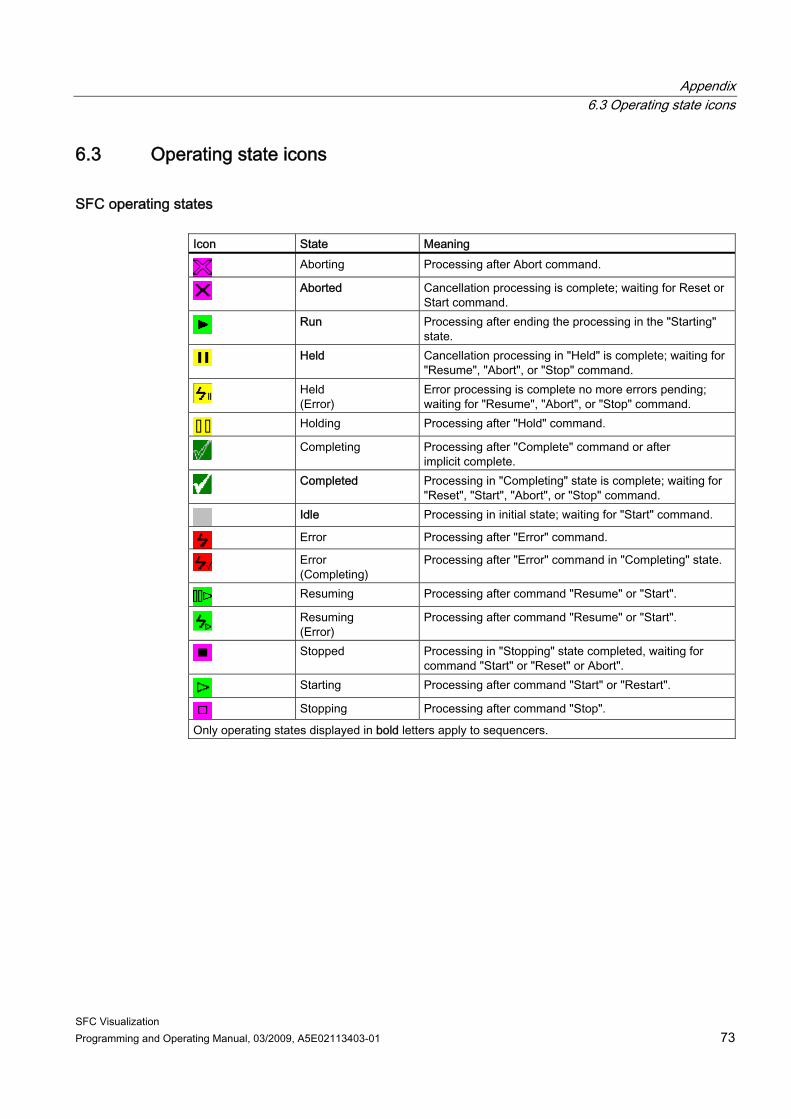
Appendix 6.3 Operating state icons
SFC Visualization Programming and Operating Manual, 03/2009, A5E02113403-01 73
6.3 Operating state icons
SFC operating states Icon State Meaning
Aborting Processing after Abort command.
Aborted Cancellation processing is complete; waiting for Reset or Start command.
Run Processing after ending the processing in the "Starting" state.
Held Cancellation processing in "Held" is complete; waiting for "Resume", "Abort", or "Stop" command.
Held (Error)
Error processing is complete no more errors pending; waiting for "Resume", "Abort", or "Stop" command.
Holding Processing after "Hold" command.
Completing Processing after "Complete" command or after implicit complete.
Completed Processing in "Completing" state is complete; waiting for "Reset", "Start", "Abort", or "Stop" command.
Idle Processing in initial state; waiting for "Start" command.
Error Processing after "Error" command.
Error (Completing)
Processing after "Error" command in "Completing" state.
Resuming Processing after command "Resume" or "Start".
Resuming (Error)
Processing after command "Resume" or "Start".
Stopped Processing in "Stopping" state completed, waiting for command "Start" or "Reset" or Abort".
Starting Processing after command "Start" or "Restart".
Stopping Processing after command "Stop".
Only operating states displayed in bold letters apply to sequencers.

Appendix 6.3 Operating state icons
SFC Visualization 74 Programming and Operating Manual, 03/2009, A5E02113403-01
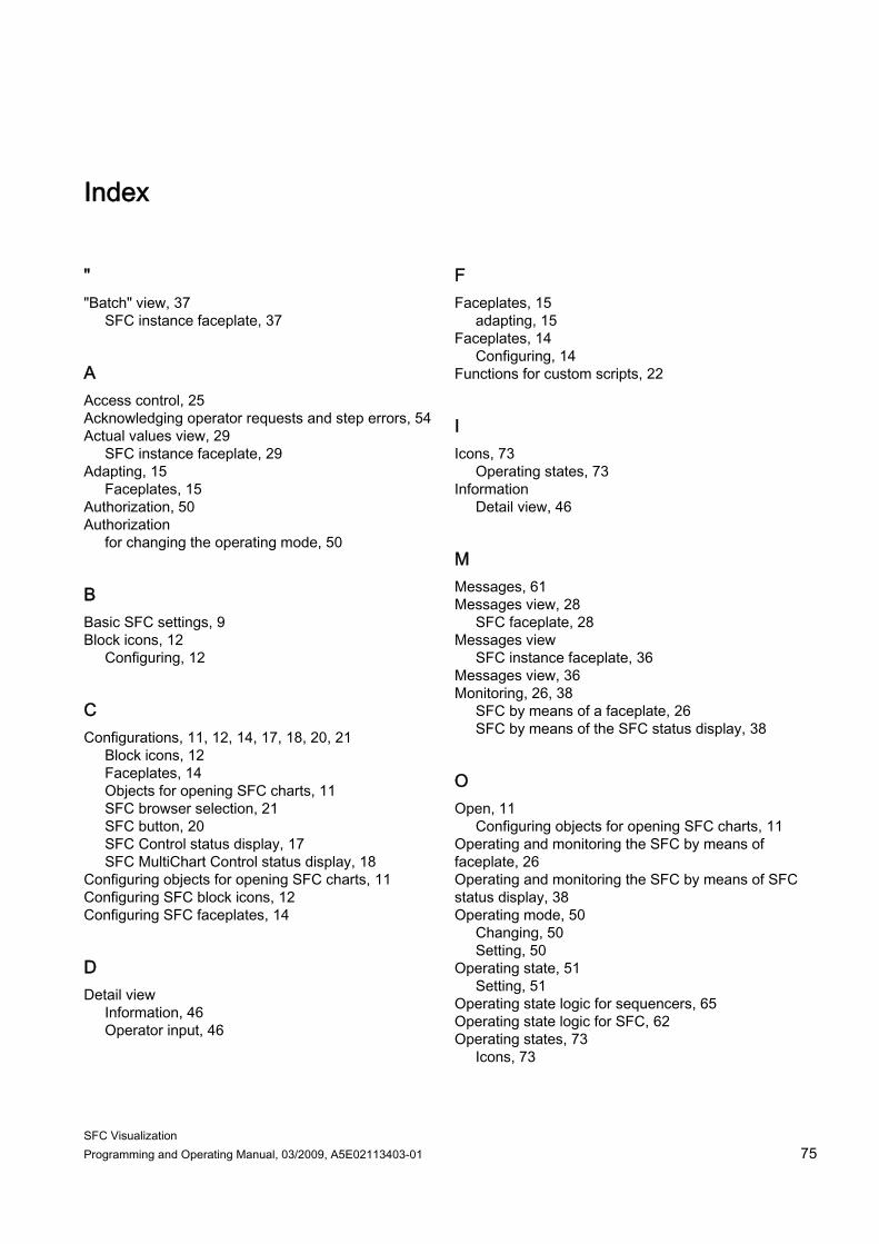
SFC Visualization Programming and Operating Manual, 03/2009, A5E02113403-01 75
Index
" "Batch" view, 37
SFC instance faceplate, 37
A Access control, 25 Acknowledging operator requests and step errors, 54 Actual values view, 29
SFC instance faceplate, 29 Adapting, 15
Faceplates, 15 Authorization, 50 Authorization
for changing the operating mode, 50
B Basic SFC settings, 9 Block icons, 12
Configuring, 12
C Configurations, 11, 12, 14, 17, 18, 20, 21
Block icons, 12 Faceplates, 14 Objects for opening SFC charts, 11 SFC browser selection, 21 SFC button, 20 SFC Control status display, 17 SFC MultiChart Control status display, 18
Configuring objects for opening SFC charts, 11 Configuring SFC block icons, 12 Configuring SFC faceplates, 14
D Detail view
Information, 46 Operator input, 46
F Faceplates, 15
adapting, 15 Faceplates, 14
Configuring, 14 Functions for custom scripts, 22
I Icons, 73
Operating states, 73 Information
Detail view, 46
M Messages, 61 Messages view, 28
SFC faceplate, 28 Messages view
SFC instance faceplate, 36 Messages view, 36 Monitoring, 26, 38
SFC by means of a faceplate, 26 SFC by means of the SFC status display, 38
O Open, 11
Configuring objects for opening SFC charts, 11 Operating and monitoring the SFC by means of faceplate, 26 Operating and monitoring the SFC by means of SFC status display, 38 Operating mode, 50
Changing, 50 Setting, 50
Operating state, 51 Setting, 51
Operating state logic for sequencers, 65 Operating state logic for SFC, 62 Operating states, 73
Icons, 73
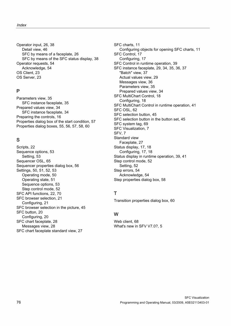
Index
SFC Visualization 76 Programming and Operating Manual, 03/2009, A5E02113403-01
Operator input, 26, 38 Detail view, 46 SFC by means of a faceplate, 26 SFC by means of the SFC status display, 38
Operator requests, 54 Acknowledge, 54
OS Client, 23 OS Server, 23
P Parameters view, 35
SFC instance faceplate, 35 Prepared values view, 34
SFC instance faceplate, 34 Preparing the controls, 16 Properties dialog box of the start condition, 57 Properties dialog boxes, 55, 56, 57, 58, 60
S Scripts, 22 Sequence options, 53
Setting, 53 Sequencer OSL, 65 Sequencer properties dialog box, 56 Settings, 50, 51, 52, 53
Operating mode, 50 Operating state, 51 Sequence options, 53 Step control mode, 52
SFC API functions, 22, 70 SFC browser selection, 21
Configuring, 21 SFC browser selection in the picture, 45 SFC button, 20
Configuring, 20 SFC chart faceplate, 28
Messages view, 28 SFC chart faceplate standard view, 27
SFC charts, 11 Configuring objects for opening SFC charts, 11
SFC Control, 17 Configuring, 17
SFC Control in runtime operation, 39 SFC instance faceplate, 29, 34, 35, 36, 37
"Batch" view, 37 Actual values view, 29 Messages view, 36 Parameters view, 35 Prepared values view, 34
SFC MultiChart Control, 18 Configuring, 18
SFC MultiChart Control in runtime operation, 41 SFC OSL, 62 SFC selection button, 45 SFC selection button in the button set, 45 SFC system tag, 69 SFC Visualization, 7 SFV, 7 Standard view
Faceplate, 27 Status display, 17, 18
Configuring, 17, 18 Status display in runtime operation, 39, 41 Step control mode, 52
Setting, 52 Step errors, 54
Acknowledge, 54 Step properties dialog box, 58
T Transition properties dialog box, 60
W Web client, 68 What's new in SFV V7.0?, 5