Embed Size (px)
Citation preview
VOLKSWAGEN/AUDI
MANUAL PROCEDURE FOR "RETURN TO BASIC SETTINGS"
Copyright © 2002 ATSG
"2003" SEMINAR INFORMATION
Automatic Transmission Service Group
SLIDE
COMPLAINT:
CAUSE:
CORRECTION:
Once a Volkswagen/Audi vehicle has been repaired, in many cases, the Transmission Module (TCM) or the Engine Control Module (ECM) does not allow proper vehicle operation.The symptoms may be, the transmission stuck in "Failsafe" or erratic shifting accompanied by driveability complaints.
It is of primary importance to clear all previously stored trouble codes, this is NOT an option.It is recommended to use a scan tool or computer based program to do this. Both are available to the aftermarket. Disconnecting the battery to accomplish this is not recommended due to other systems that may be adversely effected such as radio theft codes or the vehicle 's theft deterrent system.If no other method is available, disconnecting the battery for one minute will clear the codes.NOTE: Some codes can be cleared on OBD-II equipped vehicles using the Generic area of the scan tool if specialty equipment is not available.
The next mandatory procedure that MUST be performed is the "Return To Basic Settings" which is the Throttle Position Sensor and Kickdown relearn settings that both the TCM and the ECM must have in order to send proper commands for engine and transmission operation.
The "Return To Basic Settings" MUST be performed if any of the following conditions exist: 1. Replacement of the ECM. 2.The engine has been changed. 3. Repair or replacement of the throttle housing. 4. Replacement or adjustment of the Throttle Position Sensor. 5. Replacement of the TCM.
Use the following procedure on all VW/AUDI vehicles equipped with 096, 097,098, 01M, 01N or 01P transmissions, to manually reset the "Basic Settings":1. Turn the ignition "ON", Do not start the engine.2. Move the gear selector lever to the "D4" position.3. Depress the accelerator pedal all the way to the floor and hold it there for 30 seconds. Make certain the carpet or floor mat is not in the way of the pedal.4. After 30 seconds, move the gear selector lever back to "PARK".5. Release the accelerator pedal.6. Turn the ignition "OFF".7. After completion of the above, drive the vehicle on the road and perform three individual upshift sequences and kickdown at light, medium and heavy throttle conditions.NOTE: The systems will fine tune themselves over the next 50 to 75 miles of driving.
22
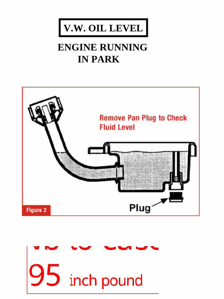
V.W. OIL LEVEL
ENGINE RUNNINGIN PARK
AUDI/VOLKSWAGEN 01M/01N
B2 & K1 CLUTCH ASSEMBLY
" 2 0 0 4 " S E M I N A R I N F O R M A T I O N
Automatic Transmission Service Group
VIDEO
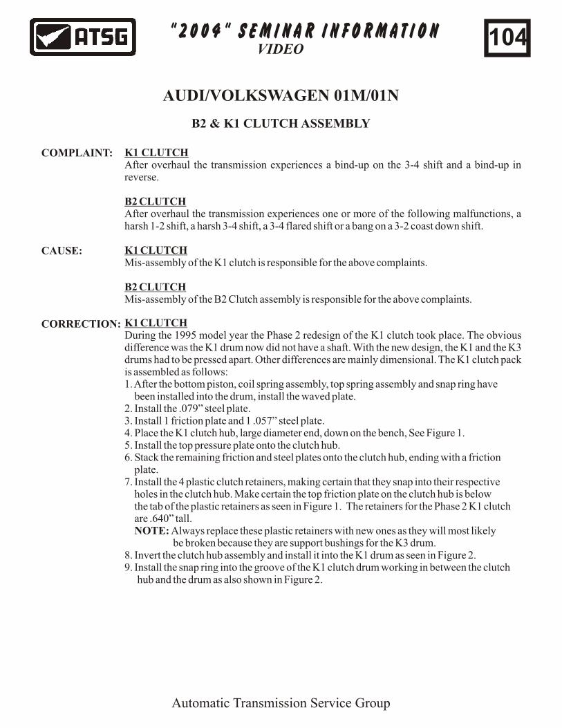
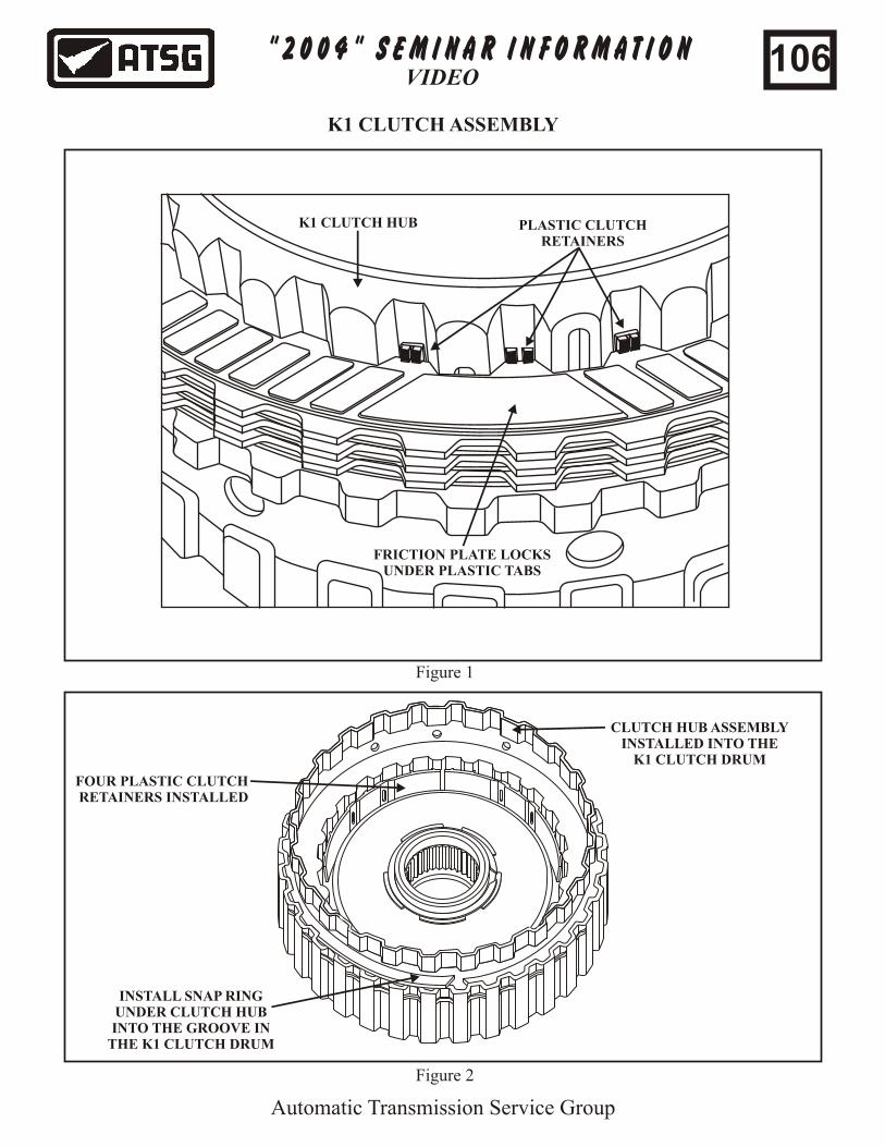
K1 CLUTCHDuring the 1995 model year the Phase 2 redesign of the K1 clutch took place. The obvious difference was the K1 drum now did not have a shaft. With the new design, the K1 and the K3 drums had to be pressed apart. Other differences are mainly dimensional. The K1 clutch pack is assembled as follows:1. After the bottom piston, coil spring assembly, top spring assembly and snap ring have been installed into the drum, install the waved plate.2. Install the .079” steel plate.3. Install 1 friction plate and 1 .057” steel plate.4. Place the K1 clutch hub, large diameter end, down on the bench, See Figure 1.5. Install the top pressure plate onto the clutch hub.6. Stack the remaining friction and steel plates onto the clutch hub, ending with a friction plate.7. Install the 4 plastic clutch retainers, making certain that they snap into their respective holes in the clutch hub. Make certain the top friction plate on the clutch hub is below the tab of the plastic retainers as seen in Figure 1. The retainers for the Phase 2 K1 clutch are .640” tall. NOTE: Always replace these plastic retainers with new ones as they will most likely be broken because they are support bushings for the K3 drum.8. Invert the clutch hub assembly and install it into the K1 drum as seen in Figure 2.9. Install the snap ring into the groove of the K1 clutch drum working in between the clutch hub and the drum as also shown in Figure 2.
K1 CLUTCHAfter overhaul the transmission experiences a bind-up on the 3-4 shift and a bind-up in reverse.
B2 CLUTCHAfter overhaul the transmission experiences one or more of the following malfunctions, a harsh 1-2 shift, a harsh 3-4 shift, a 3-4 flared shift or a bang on a 3-2 coast down shift.
K1 CLUTCHMis-assembly of the K1 clutch is responsible for the above complaints.
B2 CLUTCHMis-assembly of the B2 Clutch assembly is responsible for the above complaints.
COMPLAINT:
CAUSE:
CORRECTION:
104
" 2 0 0 4 " S E M I N A R I N F O R M A T I O N
Automatic Transmission Service Group
VIDEO
AUDI/VOLKSWAGEN 01M/01N
B2 & K1 CLUTCH ASSEMBLY
CORRECTIONcontinued:
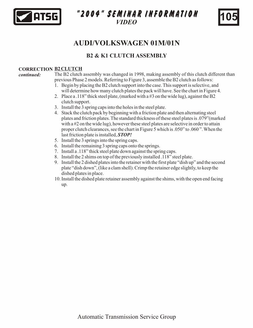
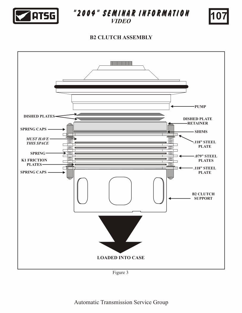
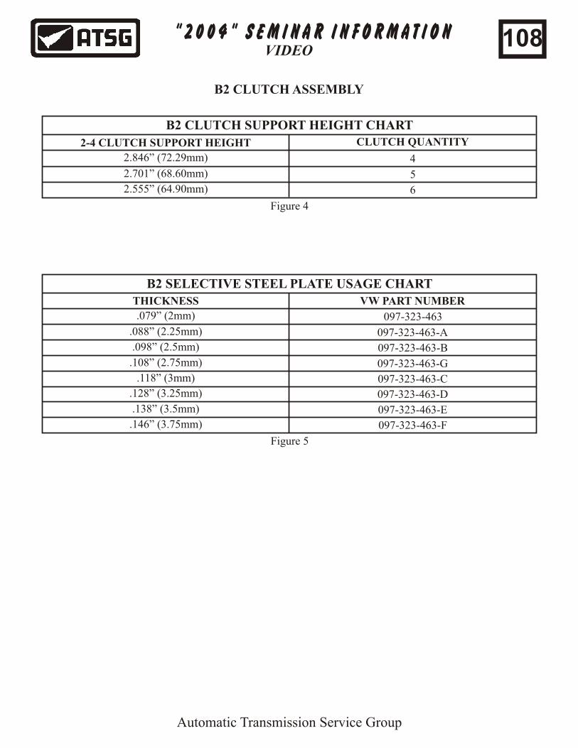
B2 CLUTCHThe B2 clutch assembly was changed in 1998, making assembly of this clutch different than previous Phase 2 models. Referring to Figure 3, assemble the B2 clutch as follows: 1. Begin by placing the B2 clutch support into the case. This support is selective, and will determine how many clutch plates the pack will have. See the chart in Figure 4.2. Place a .118” thick steel plate, (marked with a #3 on the wide lug), against the B2 clutch support.3. Install the 3 spring caps into the holes in the steel plate.4. Stack the clutch pack by beginning with a friction plate and then alternating steel plates and friction plates. The standard thickness of these steel plates is .079”(marked with a #2 on the wide lug), however these steel plates are selective in order to attain proper clutch clearances, see the chart in Figure 5 which is .050” to .060 ”. When the last friction plate is installed, STOP!5. Install the 3 springs into the spring caps.6. Install the remaining 3 spring caps onto the springs.7. Install a .118” thick steel plate down against the spring caps.8. Install the 2 shims on top of the previously installed .118” steel plate.9. Install the 2 dished plates into the retainer with the first plate “dish up” and the second plate “dish down”, (like a clam shell). Crimp the retainer edge slightly, to keep the dished plates in place.10. Install the dished plate retainer assembly against the shims, with the open end facing up.
105
" 2 0 0 4 " S E M I N A R I N F O R M A T I O N
Automatic Transmission Service Group
VIDEO
K1 CLUTCH ASSEMBLY
INSTALL SNAP RINGUNDER CLUTCH HUBINTO THE GROOVE IN
THE K1 CLUTCH DRUM
CLUTCH HUB ASSEMBLYINSTALLED INTO THE
K1 CLUTCH DRUM
FOUR PLASTIC CLUTCH RETAINERS INSTALLED
PLASTIC CLUTCHRETAINERS
FRICTION PLATE LOCKSUNDER PLASTIC TABS
K1 CLUTCH HUB
Figure 1
Figure 2
106
" 2 0 0 4 " S E M I N A R I N F O R M A T I O N
Automatic Transmission Service Group
VIDEO
B2 CLUTCH ASSEMBLY
B2 CLUTCHSUPPORT
SPRING CAPS.118” STEEL
PLATE
K1 FRICTIONPLATES
.079” STEELPLATES
SPRING
SPRING CAPS
.118” STEELPLATE
SHIMS
DISHED PLATERETAINER
DISHED PLATES
PUMP
MUST HAVETHIS SPACE
LOADED INTO CASE
Figure 3
107
" 2 0 0 4 " S E M I N A R I N F O R M A T I O N
Automatic Transmission Service Group
VIDEO
B2 CLUTCH ASSEMBLY
B2 CLUTCH SUPPORT HEIGHT CHART
2-4 CLUTCH SUPPORT HEIGHT CLUTCH QUANTITY
4
5
6
2.846” (72.29mm)
2.701” (68.60mm)
2.555” (64.90mm)
B2 SELECTIVE STEEL PLATE USAGE CHART
THICKNESS VW PART NUMBER
097-323-463
097-323-463-A
097-323-463-B
.079” (2mm)
.088” (2.25mm)
.098” (2.5mm)
.108” (2.75mm) 097-323-463-G
.118” (3mm) 097-323-463-C
097-323-463-D
097-323-463-E
097-323-463-F
.128” (3.25mm)
.138” (3.5mm)
.146” (3.75mm)
Figure 4
Figure 5
108
01M/096Rebuilding Tips
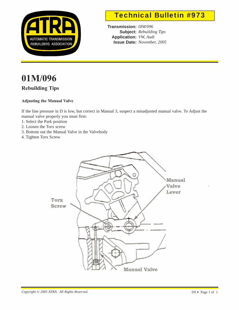
Adjusting the Manual Valve
If the line pressure in D is low, but correct in Manual 3, suspect a misadjusted manual valve. To Adjust the manual valve properly you must first:1. Select the Park position2. Loosen the Torx screw3. Bottom out the Manual Valve in the Valvebody4. Tighten Torx Screw
DS Page 1 of 1Copyright © 2005 ATRA. All Rights Reserved.
Technical Bulletin #973Transmission:
Subject:Application:Issue Date:
0IM/096Rebuilding TipsVW, AudiNovember, 2005
Page 1 of 1
17-03-2014http://www.g-tec.com/media/uploads/products/ProductMn_basic_001.jpg