Embed Size (px)
Citation preview
1
Chip Resistor Product BUYageo Corporation
June 2018
Yageo Chip Resistor Introduction
2
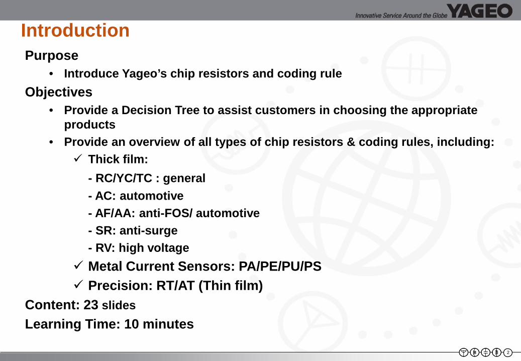
IntroductionPurpose
• Introduce Yageo’s chip resistors and coding ruleObjectives
• Provide a Decision Tree to assist customers in choosing the appropriate products
• Provide an overview of all types of chip resistors & coding rules, including: Thick film:
- RC/YC/TC : general- AC: automotive- AF/AA: anti-FOS/ automotive- SR: anti-surge- RV: high voltage
Metal Current Sensors: PA/PE/PU/PS Precision: RT/AT (Thin film)
Content: 23 slidesLearning Time: 10 minutes
‹#›
Resistor Basics
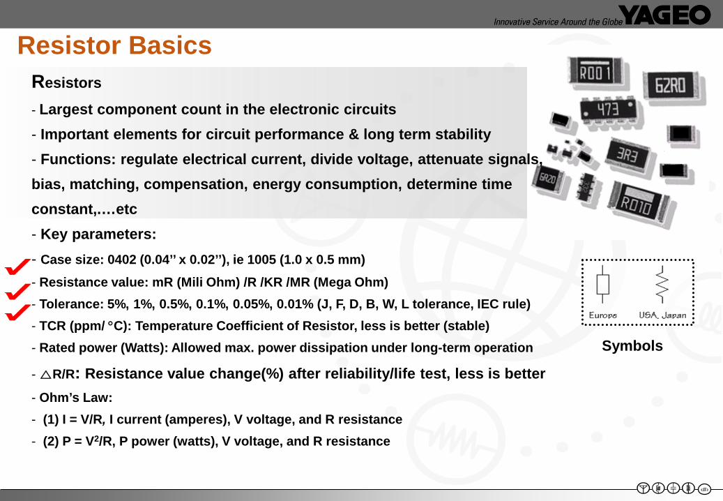
Symbols
Resistors- Largest component count in the electronic circuits- Important elements for circuit performance & long term stability- Functions: regulate electrical current, divide voltage, attenuate signals, bias, matching, compensation, energy consumption, determine time constant,.…etc- Key parameters:- Case size: 0402 (0.04’’ x 0.02’’), ie 1005 (1.0 x 0.5 mm)- Resistance value: mR (Mili Ohm) /R /KR /MR (Mega Ohm)- Tolerance: 5%, 1%, 0.5%, 0.1%, 0.05%, 0.01% (J, F, D, B, W, L tolerance, IEC rule)- TCR (ppm/ °C): Temperature Coefficient of Resistor, less is better (stable)- Rated power (Watts): Allowed max. power dissipation under long-term operation
- △R/R: Resistance value change(%) after reliability/life test, less is better- Ohm’s Law: - (1) I = V/R, I current (amperes), V voltage, and R resistance- (2) P = V2/R, P power (watts), V voltage, and R resistance
‹#›
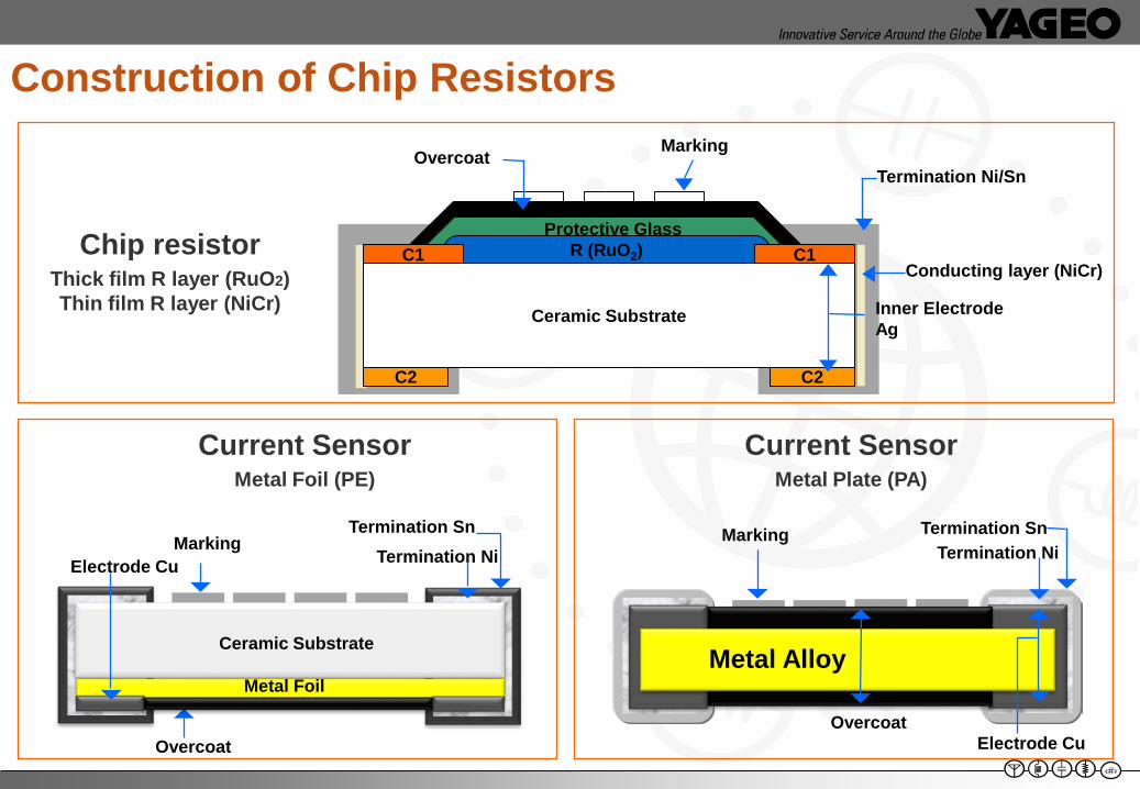
Construction of Chip Resistors
Current SensorMetal Foil (PE)
Current SensorMetal Plate (PA)
Overcoat
Metal Alloy
MarkingTermination Ni
Termination Sn
Electrode Cu
Termination Ni
Ceramic Substrate
Metal Foil
Overcoat
Electrode CuMarking
Termination Sn
Metal AlloyMetal Alloy
Chip resistorThick film R layer (RuO2) Thin film R layer (NiCr)
R (RuO2)
Ceramic Substrate
C1 C1
C2 C2
Protective Glass
Overcoat Marking
Inner Electrode Ag
Termination Ni/Sn
Conducting layer (NiCr)
5
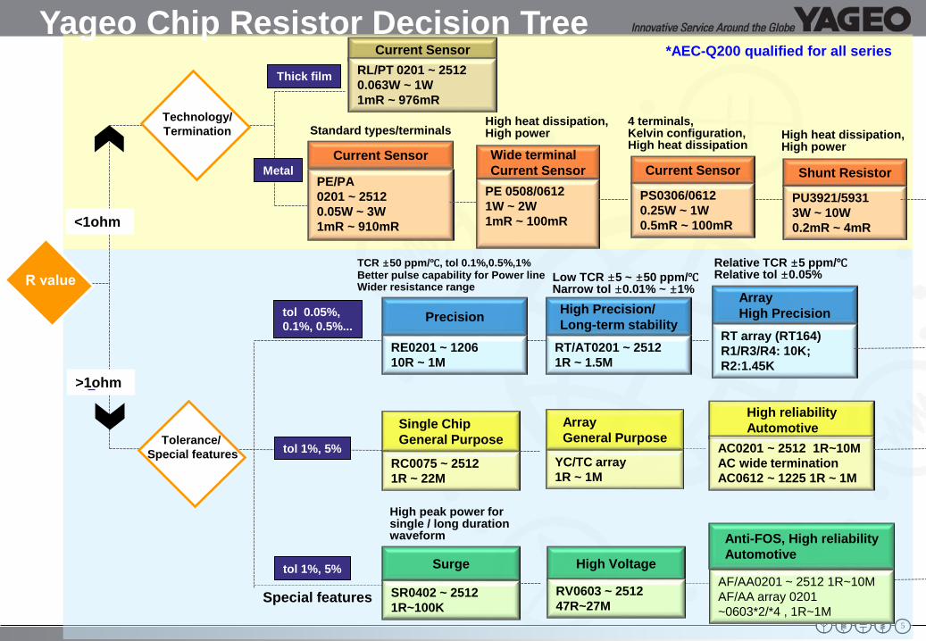
Technology/Termination
Current Sensor
PE/PA 0201 ~ 25120.05W ~ 3W1mR ~ 910mR
Standard types/terminalsHigh heat dissipation, High power
4 terminals, Kelvin configuration, High heat dissipation
Wide terminal Current Sensor
PE 0508/06121W ~ 2W1mR ~ 100mR
RC0075 ~ 25121R ~ 22M
High reliabilityAutomotive
AC0201 ~ 2512 1R~10MAC wide terminationAC0612 ~ 1225 1R ~ 1M
High Precision/Long-term stability
RT/AT0201 ~ 25121R ~ 1.5M
Precision
RE0201 ~ 120610R ~ 1M
Tolerance/ Special features
<1ohm
Low TCR ±5 ~ ±50 ppm/℃Narrow tol ±0.01% ~ ±1%
TCR ±50 ppm/℃, tol 0.1%,0.5%,1%Better pulse capability for Power line Wider resistance range
PS0306/06120.25W ~ 1W0.5mR ~ 100mR
tol 0.05%,0.1%, 0.5%...
tol 1%, 5%
Surge
SR0402 ~ 25121R~100K
High Voltage
RV0603 ~ 251247R~27M
Anti-FOS, High reliability Automotive
Special features
High peak power for single / long duration waveform
Single ChipGeneral Purpose
>1ohm
Current Sensor
Yageo Chip Resistor Decision Tree
PU3921/59313W ~ 10W0.2mR ~ 4mR
Shunt Resistor
High heat dissipation,High power
tol 1%, 5%
YC/TC array1R ~ 1M
ArrayGeneral Purpose
Current SensorRL/PT 0201 ~ 25120.063W ~ 1W 1mR ~ 976mR
Metal
Thick film
ArrayHigh Precision
RT array (RT164)R1/R3/R4: 10K; R2:1.45K
Relative TCR ±5 ppm/℃Relative tol ±0.05%
*AEC-Q200 qualified for all series
AF/AA0201 ~ 2512 1R~10MAF/AA array 0201 ~0603*2/*4 , 1R~1M
‹#›
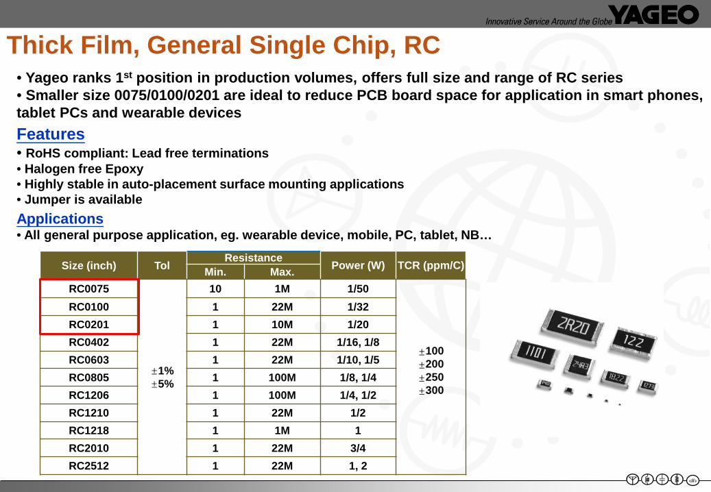
Size (inch) Tol Resistance Power (W) TCR (ppm/C)Min. Max.RC0075
±1%±5%
10 1M 1/50
±100±200±250±300
RC0100 1 22M 1/32RC0201 1 10M 1/20RC0402 1 22M 1/16, 1/8RC0603 1 22M 1/10, 1/5RC0805 1 100M 1/8, 1/4RC1206 1 100M 1/4, 1/2 RC1210 1 22M 1/2 RC1218 1 1M 1RC2010 1 22M 3/4 RC2512 1 22M 1, 2
• Yageo ranks 1st position in production volumes, offers full size and range of RC series• Smaller size 0075/0100/0201 are ideal to reduce PCB board space for application in smart phones, tablet PCs and wearable devices Features• RoHS compliant: Lead free terminations• Halogen free Epoxy• Highly stable in auto-placement surface mounting applications• Jumper is availableApplications• All general purpose application, eg. wearable device, mobile, PC, tablet, NB…
Thick Film, General Single Chip, RC
‹#›
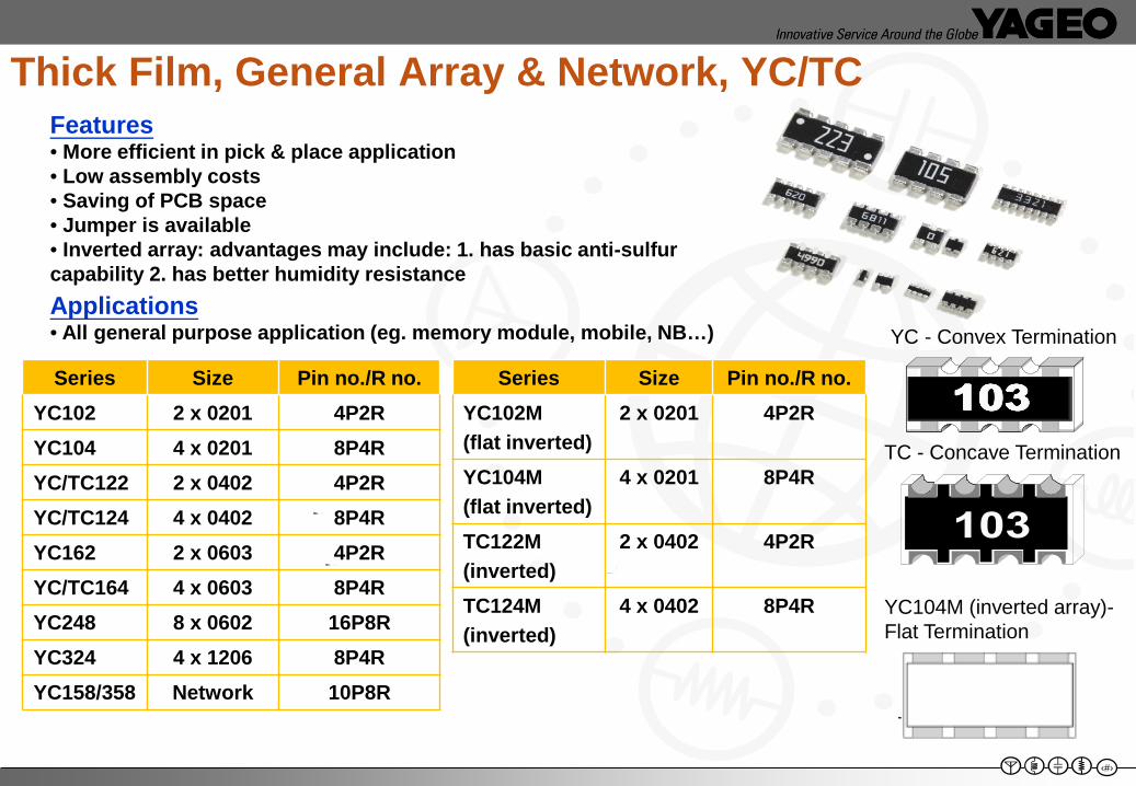
Series Size Pin no./R no.YC102 2 x 0201 4P2RYC104 4 x 0201 8P4RYC/TC122 2 x 0402 4P2RYC/TC124 4 x 0402 8P4RYC162 2 x 0603 4P2RYC/TC164 4 x 0603 8P4RYC248 8 x 0602 16P8RYC324 4 x 1206 8P4RYC158/358 Network 10P8R
YC - Convex Termination
TC - Concave Termination
Thick Film, General Array & Network, YC/TCFeatures• More efficient in pick & place application• Low assembly costs • Saving of PCB space• Jumper is available• Inverted array: advantages may include: 1. has basic anti-sulfur capability 2. has better humidity resistanceApplications• All general purpose application (eg. memory module, mobile, NB…)
Series Size Pin no./R no.YC102M (flat inverted)
2 x 0201 4P2R
YC104M(flat inverted)
4 x 0201 8P4R
TC122M(inverted)
2 x 0402 4P2R
TC124M(inverted)
4 x 0402 8P4R YC104M (inverted array)-Flat Termination
8
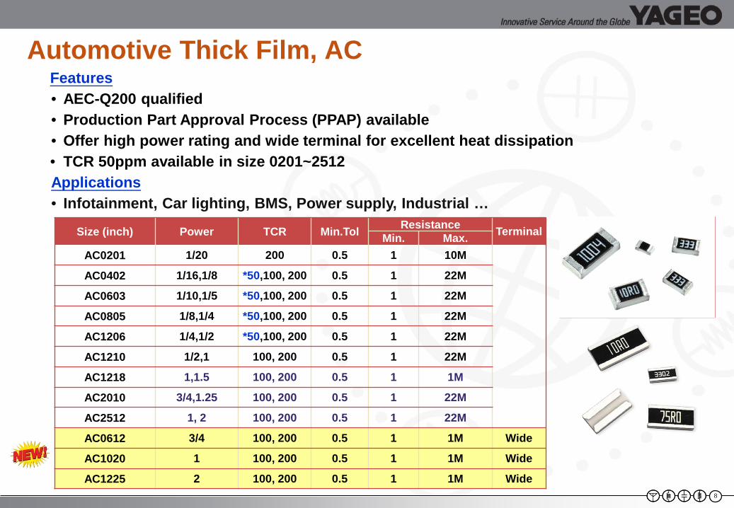
Features• AEC-Q200 qualified• Production Part Approval Process (PPAP) available• Offer high power rating and wide terminal for excellent heat dissipation• TCR 50ppm available in size 0201~2512Applications• Infotainment, Car lighting, BMS, Power supply, Industrial …
Automotive Thick Film, AC
Size (inch) Power TCR Min.Tol Resistance TerminalMin. Max.AC0201 1/20 200 0.5 1 10M
AC0402 1/16,1/8 *50,100, 200 0.5 1 22M
AC0603 1/10,1/5 *50,100, 200 0.5 1 22M
AC0805 1/8,1/4 *50,100, 200 0.5 1 22M
AC1206 1/4,1/2 *50,100, 200 0.5 1 22M
AC1210 1/2,1 100, 200 0.5 1 22M
AC1218 1,1.5 100, 200 0.5 1 1M
AC2010 3/4,1.25 100, 200 0.5 1 22M
AC2512 1, 2 100, 200 0.5 1 22M
AC0612 3/4 100, 200 0.5 1 1M Wide
AC1020 1 100, 200 0.5 1 1M Wide
AC1225 2 100, 200 0.5 1 1M Wide
‹#›
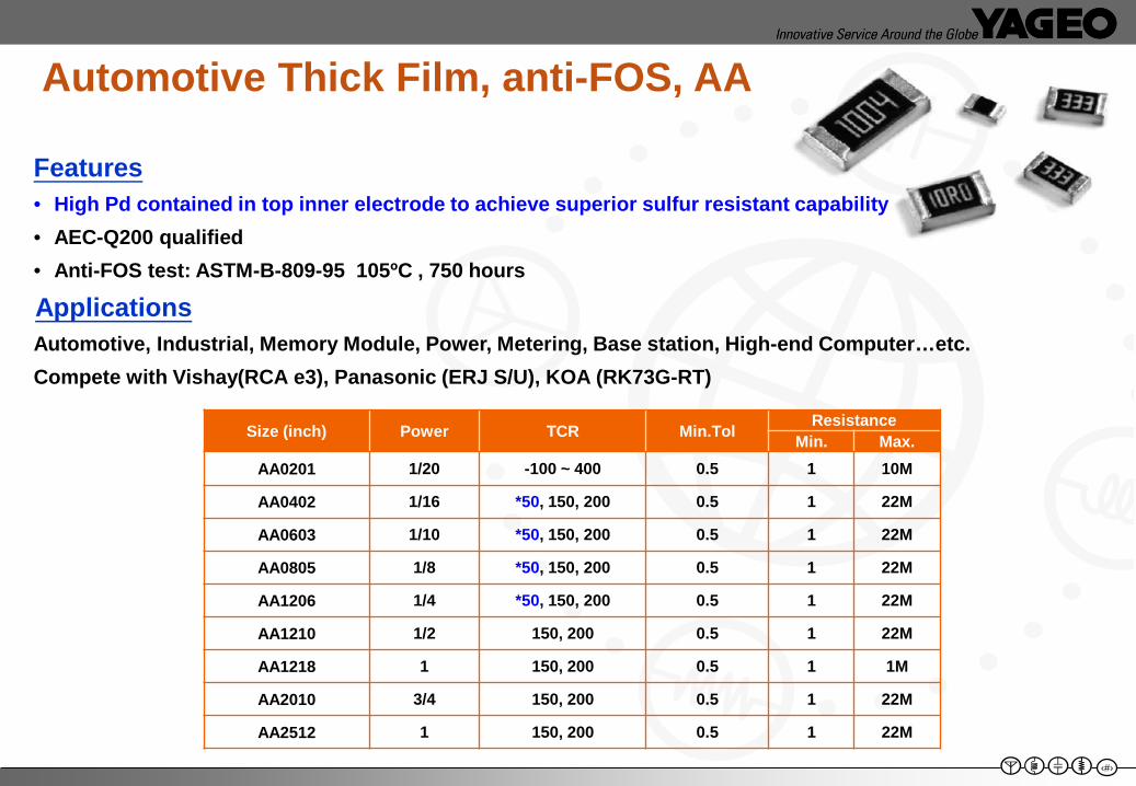
Features• High Pd contained in top inner electrode to achieve superior sulfur resistant capability• AEC-Q200 qualified• Anti-FOS test: ASTM-B-809-95 105ºC , 750 hours
ApplicationsAutomotive, Industrial, Memory Module, Power, Metering, Base station, High-end Computer…etc.Compete with Vishay(RCA e3), Panasonic (ERJ S/U), KOA (RK73G-RT)
Automotive Thick Film, anti-FOS, AA
Size (inch) Power TCR Min.Tol ResistanceMin. Max.
AA0201 1/20 -100 ~ 400 0.5 1 10M
AA0402 1/16 *50, 150, 200 0.5 1 22M
AA0603 1/10 *50, 150, 200 0.5 1 22M
AA0805 1/8 *50, 150, 200 0.5 1 22M
AA1206 1/4 *50, 150, 200 0.5 1 22M
AA1210 1/2 150, 200 0.5 1 22M
AA1218 1 150, 200 0.5 1 1M
AA2010 3/4 150, 200 0.5 1 22M
AA2512 1 150, 200 0.5 1 22M
10
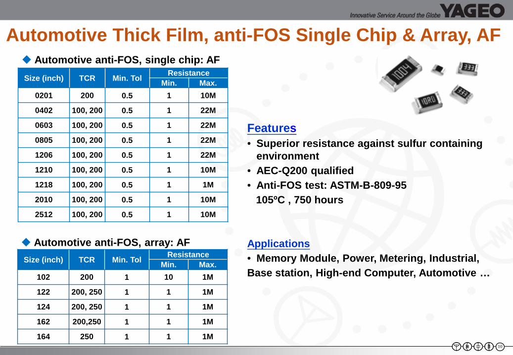
Automotive Thick Film, anti-FOS Single Chip & Array, AF
Size (inch) TCR Min. Tol ResistanceMin. Max.
0201 200 0.5 1 10M
0402 100, 200 0.5 1 22M
0603 100, 200 0.5 1 22M
0805 100, 200 0.5 1 22M
1206 100, 200 0.5 1 22M
1210 100, 200 0.5 1 10M
1218 100, 200 0.5 1 1M
2010 100, 200 0.5 1 10M
2512 100, 200 0.5 1 10M
Automotive anti-FOS, single chip: AF
Automotive anti-FOS, array: AF
Features• Superior resistance against sulfur containing
environment• AEC-Q200 qualified• Anti-FOS test: ASTM-B-809-95
105ºC , 750 hours
Applications• Memory Module, Power, Metering, Industrial, Base station, High-end Computer, Automotive …
Size (inch) TCR Min. Tol ResistanceMin. Max.
102 200 1 10 1M
122 200, 250 1 1 1M
124 200, 250 1 1 1M
162 200,250 1 1 1M
164 250 1 1 1M
11
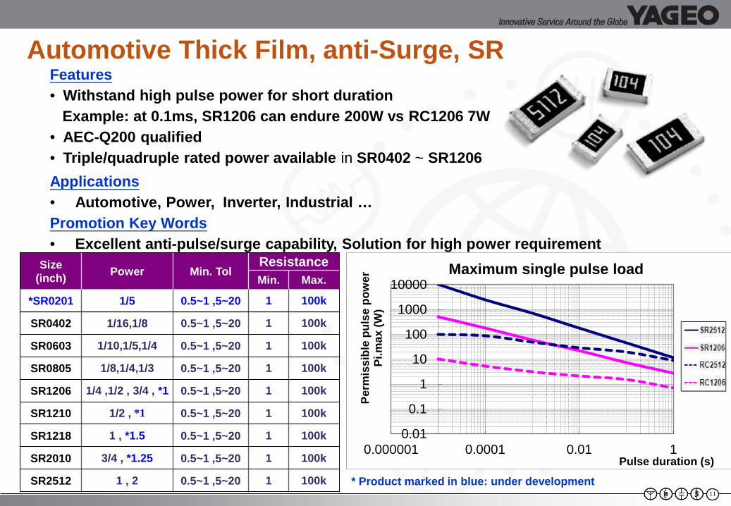
Size (inch) Power Min. Tol
ResistanceMin. Max.
*SR0201 1/5 0.5~1 ,5~20 1 100k
SR0402 1/16,1/8 0.5~1 ,5~20 1 100k
SR0603 1/10,1/5,1/4 0.5~1 ,5~20 1 100k
SR0805 1/8,1/4,1/3 0.5~1 ,5~20 1 100k
SR1206 1/4 ,1/2 , 3/4 , *1 0.5~1 ,5~20 1 100k
SR1210 1/2 , *1 0.5~1 ,5~20 1 100k
SR1218 1 , *1.5 0.5~1 ,5~20 1 100k
SR2010 3/4 , *1.25 0.5~1 ,5~20 1 100k
SR2512 1 , 2 0.5~1 ,5~20 1 100k
Features• Withstand high pulse power for short duration
Example: at 0.1ms, SR1206 can endure 200W vs RC1206 7W • AEC-Q200 qualified• Triple/quadruple rated power available in SR0402 ~ SR1206Applications• Automotive, Power, Inverter, Industrial …Promotion Key Words• Excellent anti-pulse/surge capability, Solution for high power requirement
Automotive Thick Film, anti-Surge, SR
0.01
0.1
1
10
100
1000
10000
0.000001 0.0001 0.01 1
Perm
issi
ble
puls
e po
wer
Pi
.max
(W)
Pulse duration (s)
Maximum single pulse load
* Product marked in blue: under development
12
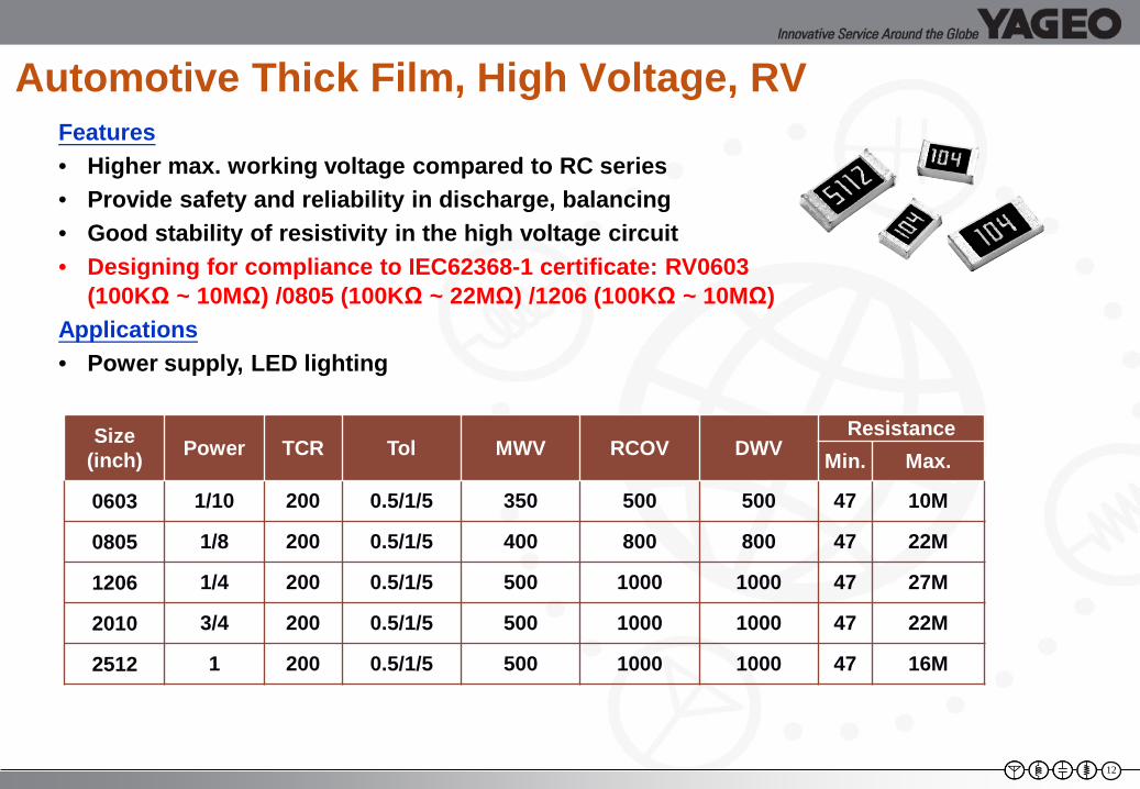
Automotive Thick Film, High Voltage, RV
Size (inch) Power TCR Tol MWV RCOV DWV
ResistanceMin. Max.
0603 1/10 200 0.5/1/5 350 500 500 47 10M
0805 1/8 200 0.5/1/5 400 800 800 47 22M
1206 1/4 200 0.5/1/5 500 1000 1000 47 27M
2010 3/4 200 0.5/1/5 500 1000 1000 47 22M
2512 1 200 0.5/1/5 500 1000 1000 47 16M
Features• Higher max. working voltage compared to RC series• Provide safety and reliability in discharge, balancing • Good stability of resistivity in the high voltage circuit• Designing for compliance to IEC62368-1 certificate: RV0603
(100KΩ ~ 10MΩ) /0805 (100KΩ ~ 22MΩ) /1206 (100KΩ ~ 10MΩ) Applications• Power supply, LED lighting
13
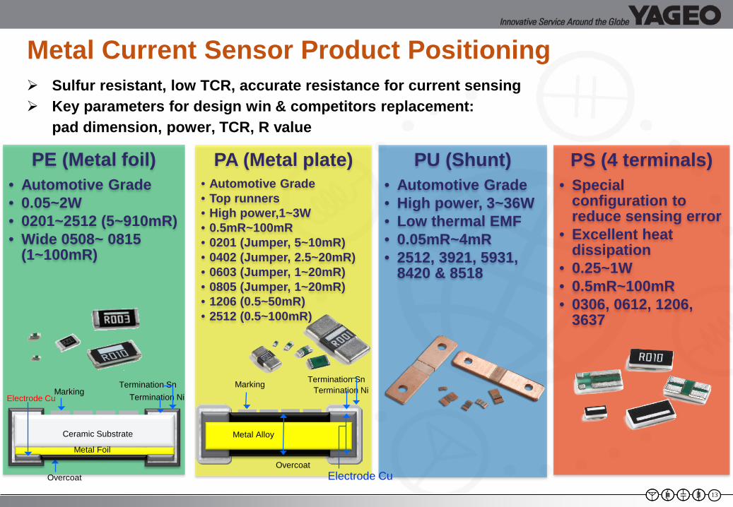
Metal Current Sensor Product Positioning Sulfur resistant, low TCR, accurate resistance for current sensing Key parameters for design win & competitors replacement:
pad dimension, power, TCR, R value
PE (Metal foil)• Automotive Grade• 0.05~2W• 0201~2512 (5~910mR)• Wide 0508~ 0815
(1~100mR)
PA (Metal plate)• Automotive Grade• Top runners• High power,1~3W • 0.5mR~100mR• 0201 (Jumper, 5~10mR)• 0402 (Jumper, 2.5~20mR)• 0603 (Jumper, 1~20mR)• 0805 (Jumper, 1~20mR)• 1206 (0.5~50mR)• 2512 (0.5~100mR)
PU (Shunt)• Automotive Grade• High power, 3~36W• Low thermal EMF• 0.05mR~4mR• 2512, 3921, 5931,
8420 & 8518
PS (4 terminals)• Special
configuration to reduce sensing error
• Excellent heat dissipation
• 0.25~1W• 0.5mR~100mR• 0306, 0612, 1206,
3637
Termination Ni
Ceramic Substrate
Metal Foil
Overcoat
Electrode CuMarking
Termination Sn
Overcoat
Metal Alloy
MarkingTermination Ni
Termination Sn
Electrode Cu
Metal AlloyMetal Alloy
‹#›
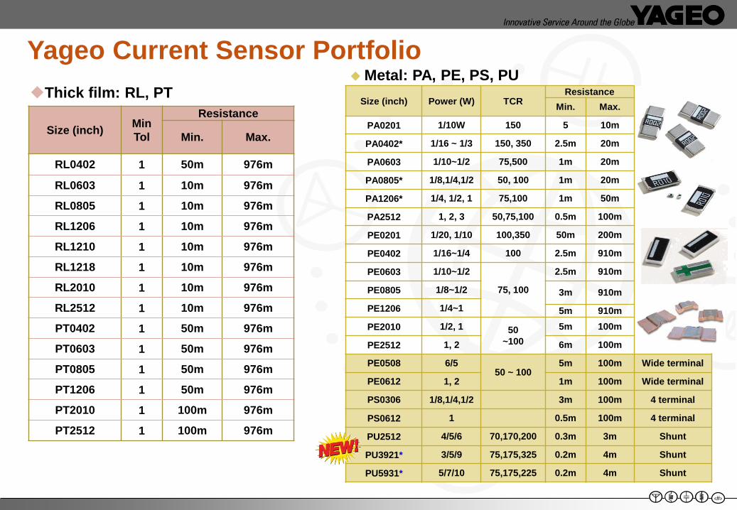
Size (inch) Min Tol
Resistance
Min. Max.
RL0402 1 50m 976m
RL0603 1 10m 976m
RL0805 1 10m 976m
RL1206 1 10m 976m
RL1210 1 10m 976m
RL1218 1 10m 976m
RL2010 1 10m 976m
RL2512 1 10m 976m
PT0402 1 50m 976m
PT0603 1 50m 976m
PT0805 1 50m 976m
PT1206 1 50m 976m
PT2010 1 100m 976m
PT2512 1 100m 976m
Thick film: RL, PTMetal: PA, PE, PS, PU
Yageo Current Sensor PortfolioSize (inch) Power (W) TCR
ResistanceMin. Max.
PA0201 1/10W 150 5 10m
PA0402* 1/16 ~ 1/3 150, 350 2.5m 20m
PA0603 1/10~1/2 75,500 1m 20m
PA0805* 1/8,1/4,1/2 50, 100 1m 20m
PA1206* 1/4, 1/2, 1 75,100 1m 50m
PA2512 1, 2, 3 50,75,100 0.5m 100m
PE0201 1/20, 1/10 100,350 50m 200m
PE0402 1/16~1/4 100 2.5m 910m
PE0603 1/10~1/2
75, 100
2.5m 910m
PE0805 1/8~1/2 3m 910mPE1206 1/4~1 5m 910mPE2010 1/2, 1 50
~1005m 100m
PE2512 1, 2 6m 100m
PE0508 6/550 ~ 100
5m 100m Wide terminal
PE0612 1, 2 1m 100m Wide terminal
PS0306 1/8,1/4,1/2 3m 100m 4 terminal
PS0612 1 0.5m 100m 4 terminal
PU2512 4/5/6 70,170,200 0.3m 3m Shunt
PU3921* 3/5/9 75,175,325 0.2m 4m Shunt
PU5931* 5/7/10 75,175,225 0.2m 4m Shunt
‹#›
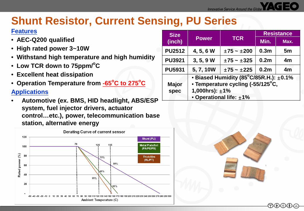
Size (inch) Power TCR
ResistanceMin. Max.
PU2512 4, 5, 6 W ±75 ~ ±200 0.3m 5mPU3921 3, 5, 9 W ±75 ~ ±325 0.2m 4mPU5931 5, 7, 10W ±75 ~ ±225 0.2m 4m
Major spec
• Biased Humidity (85oC/85R.H.): ±0.1%• Temperature cycling (-55/125oC, 1,000hrs): ±1% • Operational life: ±1%
Features• AEC-Q200 qualified• High rated power 3~10W• Withstand high temperature and high humidity• Low TCR down to 75ppm/oC• Excellent heat dissipation• Operation Temperature from -65oC to 275oCApplications• Automotive (ex. BMS, HID headlight, ABS/ESP
system, fuel injector drivers, actuator control…etc.), power, telecommunication base station, alternative energy
Shunt Resistor, Current Sensing, PU Series
‹#›
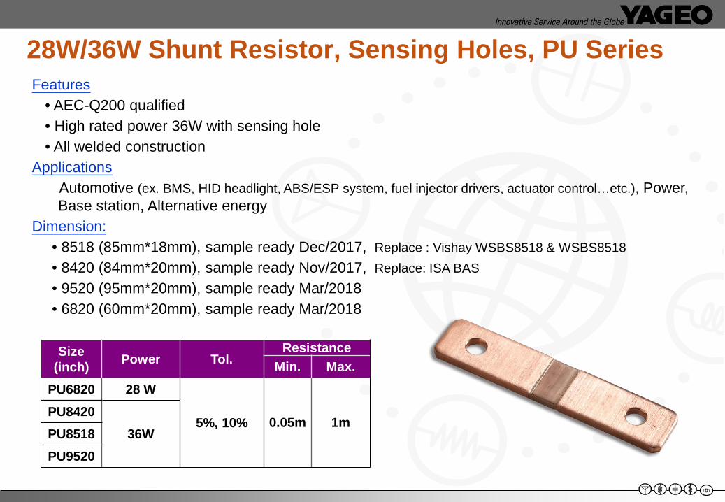
Size (inch) Power Tol.
ResistanceMin. Max.
PU6820 28 W
5%, 10% 0.05m 1mPU8420
36WPU8518PU9520
Features• AEC-Q200 qualified• High rated power 36W with sensing hole• All welded construction
ApplicationsAutomotive (ex. BMS, HID headlight, ABS/ESP system, fuel injector drivers, actuator control…etc.), Power, Base station, Alternative energy
Dimension: • 8518 (85mm*18mm), sample ready Dec/2017, Replace : Vishay WSBS8518 & WSBS8518• 8420 (84mm*20mm), sample ready Nov/2017, Replace: ISA BAS• 9520 (95mm*20mm), sample ready Mar/2018• 6820 (60mm*20mm), sample ready Mar/2018
28W/36W Shunt Resistor, Sensing Holes, PU Series
‹#›
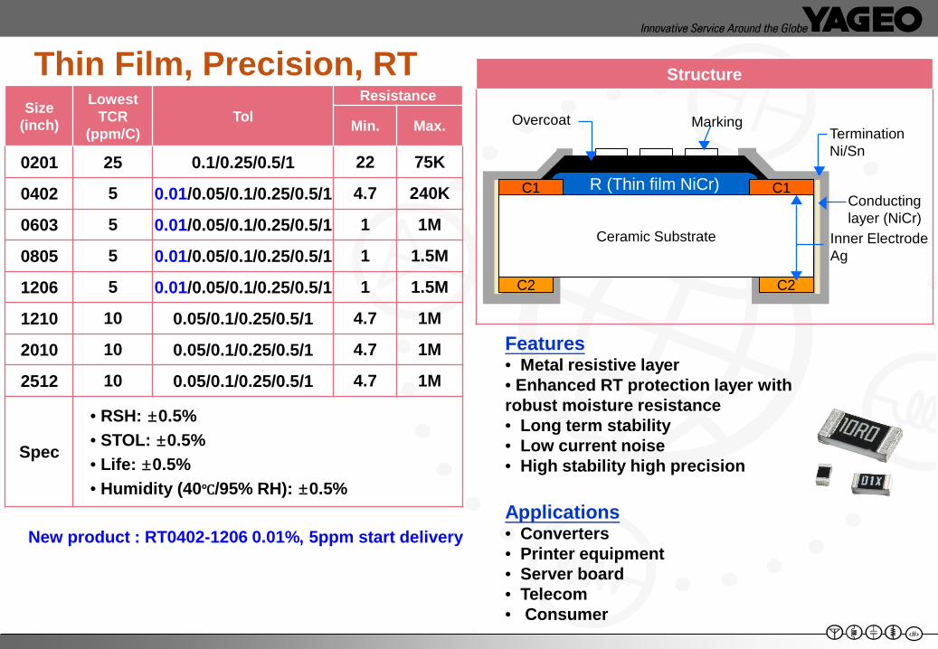
Thin Film, Precision, RTSize
(inch)
Lowest TCR
(ppm/C)Tol
Resistance
Min. Max.
0201 25 0.1/0.25/0.5/1 22 75K
0402 5 0.01/0.05/0.1/0.25/0.5/1 4.7 240K
0603 5 0.01/0.05/0.1/0.25/0.5/1 1 1M
0805 5 0.01/0.05/0.1/0.25/0.5/1 1 1.5M
1206 5 0.01/0.05/0.1/0.25/0.5/1 1 1.5M
1210 10 0.05/0.1/0.25/0.5/1 4.7 1M
2010 10 0.05/0.1/0.25/0.5/1 4.7 1M
2512 10 0.05/0.1/0.25/0.5/1 4.7 1M
Spec
• RSH: ±0.5%• STOL: ±0.5%• Life: ±0.5%• Humidity (40℃/95% RH): ±0.5%
Features• Metal resistive layer• Enhanced RT protection layer with robust moisture resistance• Long term stability• Low current noise• High stability high precision
Applications• Converters • Printer equipment • Server board • Telecom • Consumer
Structure
R (Thin film NiCr)
Ceramic Substrate
C1 C1
C2 C2
Overcoat Marking
Inner Electrode Ag
Termination Ni/Sn
Conducting layer (NiCr)
New product : RT0402-1206 0.01%, 5ppm start delivery
‹#›
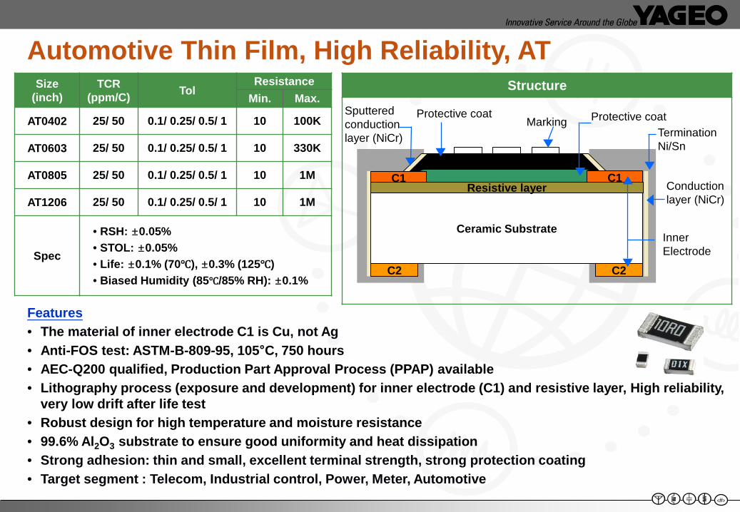
Automotive Thin Film, High Reliability, AT
Features• The material of inner electrode C1 is Cu, not Ag• Anti-FOS test: ASTM-B-809-95, 105°C, 750 hours• AEC-Q200 qualified, Production Part Approval Process (PPAP) available• Lithography process (exposure and development) for inner electrode (C1) and resistive layer, High reliability,
very low drift after life test• Robust design for high temperature and moisture resistance• 99.6% Al2O3 substrate to ensure good uniformity and heat dissipation• Strong adhesion: thin and small, excellent terminal strength, strong protection coating• Target segment : Telecom, Industrial control, Power, Meter, Automotive
StructureSize (inch)
TCR(ppm/C) Tol
ResistanceMin. Max.
AT0402 25/ 50 0.1/ 0.25/ 0.5/ 1 10 100K
AT0603 25/ 50 0.1/ 0.25/ 0.5/ 1 10 330K
AT0805 25/ 50 0.1/ 0.25/ 0.5/ 1 10 1M
AT1206 25/ 50 0.1/ 0.25/ 0.5/ 1 10 1M
Spec
• RSH: ±0.05%• STOL: ±0.05%• Life: ±0.1% (70℃), ±0.3% (125℃)• Biased Humidity (85℃/85% RH): ±0.1%
BBBBBB
Ceramic Substrate
C1 C1
C2 C2
Protective coatMarking
Inner Electrode
Termination Ni/Sn
Conduction layer (NiCr)
Resistive layer
Protective coatSputtered conduction layer (NiCr)
‹#›
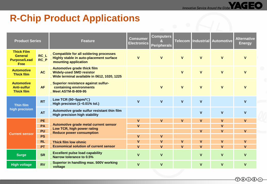
R-Chip Product Applications
Product Series Feature Consumer Electronics
Computers &
PeripheralsTelecom Industrial Automotive Alternative
Energy
Thick Film General
Purpose/Lead Free
RC_LRC_P
.Compatible for all soldering processes.Highly stable in auto-placement surface
mounting applicationV V V V V V
AutomotiveThick film AC
.Automotive grade thick film.Widely-used SMD resistor.Wide terminal available in 0612, 1020, 1225
V V V V
AutomotiveAnti-sulfur Thick film
AF.Superior resistance against sulfur-
containing environments.Meet ASTM-B-809-95
V V V V V
Thin film high precision
RT .Low TCR (50~5ppm/℃).High precision (1~0.01% tol.) V V V V V
AT .Automotive grade sulfur resistant thin film.High precision high stability V V V
Current sensor
PE.Automotive grade metal current sensor.Low TCR, high power rating.Reduce power consumption
V V V V V VPA V VPU V V VPS V VRL .Thick film low ohmic
.Economical solution of current sensorV V V V V V
PT V V V V V V
Surge SR .Excellent pulse load capability.Narrow tolerance to 0.5% V V V V V
High voltage RV .Superior in handling max. 500V working voltage V V V V V
20
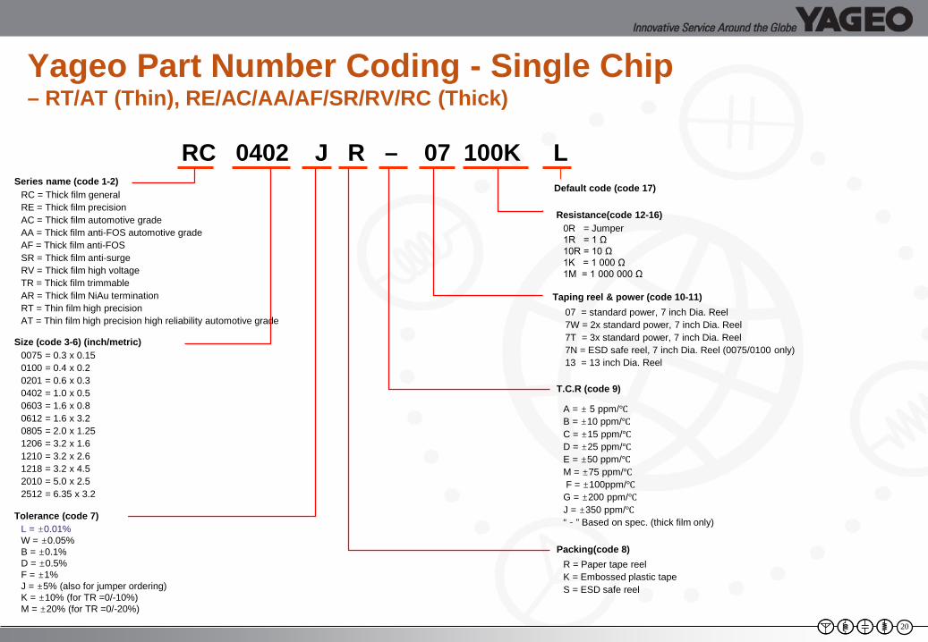
Yageo Part Number Coding - Single Chip – RT/AT (Thin), RE/AC/AA/AF/SR/RV/RC (Thick)
RC 0402 J R – 07 100K L
0R = Jumper1R = 1 Ω10R = 10 Ω1K = 1 000 Ω1M = 1 000 000 Ω
A = ± 5 ppm/℃B = ±10 ppm/℃C = ±15 ppm/℃D = ±25 ppm/℃E = ±50 ppm/℃M = ±75 ppm/℃F = ±100ppm/℃
G = ±200 ppm/℃J = ±350 ppm/℃“-” Based on spec. (thick film only)
R = Paper tape reelK = Embossed plastic tapeS = ESD safe reel
Series name (code 1-2)RC = Thick film generalRE = Thick film precisionAC = Thick film automotive gradeAA = Thick film anti-FOS automotive gradeAF = Thick film anti-FOSSR = Thick film anti-surgeRV = Thick film high voltageTR = Thick film trimmableAR = Thick film NiAu termination RT = Thin film high precisionAT = Thin film high precision high reliability automotive grade
0075 = 0.3 x 0.150100 = 0.4 x 0.20201 = 0.6 x 0.30402 = 1.0 x 0.50603 = 1.6 x 0.80612 = 1.6 x 3.20805 = 2.0 x 1.251206 = 3.2 x 1.61210 = 3.2 x 2.61218 = 3.2 x 4.52010 = 5.0 x 2.52512 = 6.35 x 3.2
L = ±0.01%W = ±0.05%B = ±0.1%D = ±0.5%F = ±1%J = ±5% (also for jumper ordering)K = ±10% (for TR =0/-10%)M = ±20% (for TR =0/-20%)
07 = standard power, 7 inch Dia. Reel7W = 2x standard power, 7 inch Dia. Reel7T = 3x standard power, 7 inch Dia. Reel7N = ESD safe reel, 7 inch Dia. Reel (0075/0100 only)13 = 13 inch Dia. Reel
Size (code 3-6) (inch/metric)
Tolerance (code 7)
Default code (code 17)
Resistance(code 12-16)
Taping reel & power (code 10-11)
T.C.R (code 9)
Packing(code 8)
21
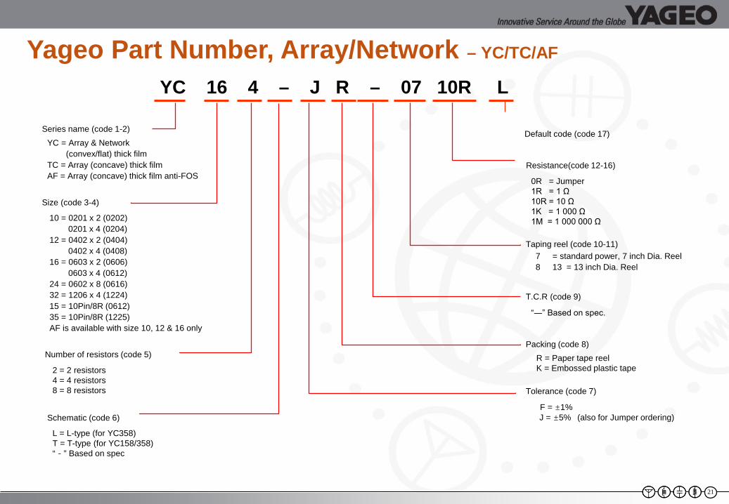
Yageo Part Number, Array/Network – YC/TC/AF
YC 16 4 – J R – 07 10R L
“―” Based on spec.
R = Paper tape reelK = Embossed plastic tape
F = ±1%J = ±5% (also for Jumper ordering)
YC = Array & Network (convex/flat) thick film
TC = Array (concave) thick filmAF = Array (concave) thick film anti-FOS
10 = 0201 x 2 (0202)0201 x 4 (0204)
12 = 0402 x 2 (0404)0402 x 4 (0408)
16 = 0603 x 2 (0606)0603 x 4 (0612)
24 = 0602 x 8 (0616)32 = 1206 x 4 (1224)15 = 10Pin/8R (0612)35 = 10Pin/8R (1225)AF is available with size 10, 12 & 16 only
Number of resistors (code 5)
2 = 2 resistors4 = 4 resistors8 = 8 resistors
Schematic (code 6)
L = L-type (for YC358)T = T-type (for YC158/358)“-” Based on spec
0R = Jumper1R = 1 Ω10R = 10 Ω1K = 1 000 Ω1M = 1 000 000 Ω
7 = standard power, 7 inch Dia. Reel8 13 = 13 inch Dia. Reel
Taping reel (code 10-11)
Series name (code 1-2)
Size (code 3-4)
Tolerance (code 7)
Default code (code 17)
Resistance(code 12-16)
T.C.R (code 9)
Packing (code 8)
22
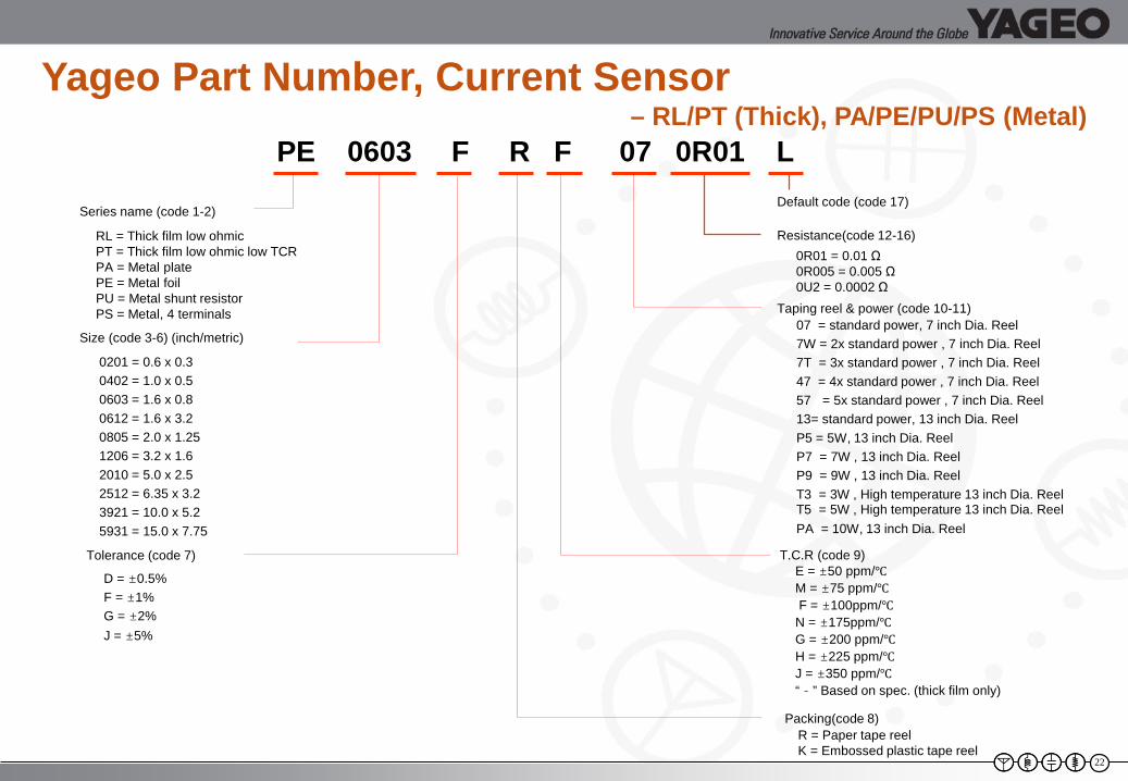
Yageo Part Number, Current Sensor – RL/PT (Thick), PA/PE/PU/PS (Metal)
PE 0603 F R F 07 0R01 L
RL = Thick film low ohmicPT = Thick film low ohmic low TCRPA = Metal platePE = Metal foilPU = Metal shunt resistorPS = Metal, 4 terminals
0201 = 0.6 x 0.30402 = 1.0 x 0.50603 = 1.6 x 0.80612 = 1.6 x 3.20805 = 2.0 x 1.251206 = 3.2 x 1.62010 = 5.0 x 2.52512 = 6.35 x 3.23921 = 10.0 x 5.25931 = 15.0 x 7.75
07 = standard power, 7 inch Dia. Reel7W = 2x standard power , 7 inch Dia. Reel7T = 3x standard power , 7 inch Dia. Reel47 = 4x standard power , 7 inch Dia. Reel57 = 5x standard power , 7 inch Dia. Reel13= standard power, 13 inch Dia. ReelP5 = 5W, 13 inch Dia. ReelP7 = 7W , 13 inch Dia. ReelP9 = 9W , 13 inch Dia. ReelT3 = 3W , High temperature 13 inch Dia. ReelT5 = 5W , High temperature 13 inch Dia. ReelPA = 10W, 13 inch Dia. Reel
Series name (code 1-2)
Size (code 3-6) (inch/metric)
Tolerance (code 7)
Default code (code 17)
Resistance(code 12-16)
Taping reel & power (code 10-11)
T.C.R (code 9)
Packing(code 8)
E = ±50 ppm/℃M = ±75 ppm/℃F = ±100ppm/℃
N = ±175ppm/℃G = ±200 ppm/℃H = ±225 ppm/℃J = ±350 ppm/℃“-” Based on spec. (thick film only)
D = ±0.5%F = ±1%G = ±2%J = ±5%
0R01 = 0.01 Ω0R005 = 0.005 Ω0U2 = 0.0002 Ω
R = Paper tape reelK = Embossed plastic tape reel
23
Summary
• Provided a basic explanation of how the chip resistors are made
• Introduced their Thin/ Thick Film, Metal product offering • Provided an overview of resistor networks and low ohm
current sense resistors• Explored Yageo’s part number breakdowns and RoHS
labeling

24
Thanks for your attention!