Embed Size (px)
Citation preview
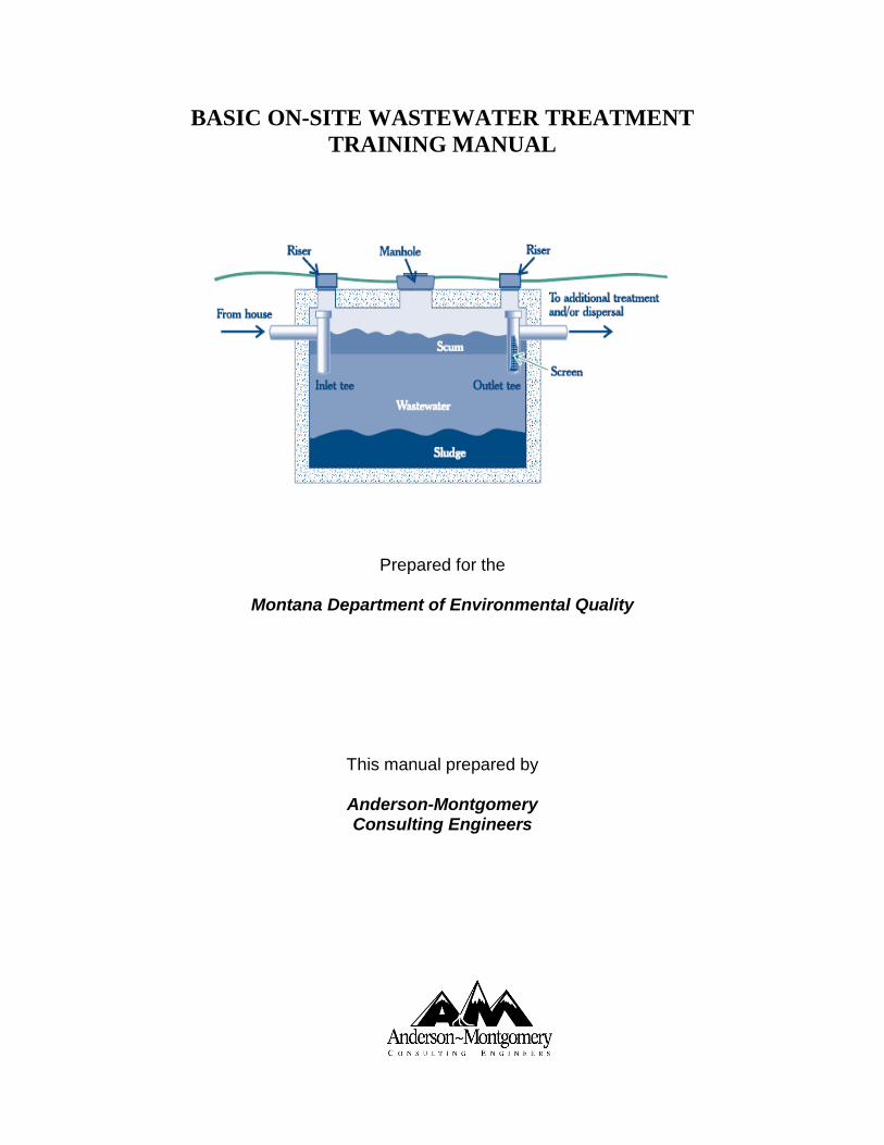
BASIC ON-SITE WASTEWATER TREATMENT TRAINING MANUAL
Prepared for the
Montana Department of Environmental Quality
This manual prepared by
Anderson-Montgomery Consulting Engineers
i
BASIC ON-SITE WASTEWATER TREATMENT TRAINING MANUAL
June 2012 1st Printing
TABLE OF CONTENTS
Subject Page Number INTRODUCTION i - vi CHAPTER 1 WHO HAS RESPONSIBILITY?
Who Has Responsibility? 1 Self-Study Questions 4
CHAPTER 2 WHAT IS WASTEWATER? What is Wastewater? 1
Wastewater Analysis 6 Self-Study Questions 8
CHAPTER 3 ON-SITE TREATMENT SYSTEMS Biology of On-Site Systems 1
Pretreatment 4 Absorption Disposal 9 Self-Study Questions 15
CHAPTER 4 WASTEWATER COLLECTION Collection Systems 1 Pump Stations, Pumps and Motors 2 Motors and Electricity 5 Self-Study Questions 7 CHAPTER 5 REGULATIONS Laws, Regulations, Permits 1
Biosolids Disposal 4 Operator Certification 5
Self-Study Questions 8
CHAPTER 6 SAMPLING Sampling 1
Self-Study Questions 6 CHAPTER 7 SAFETY General 1 Chemicals 1 Electrical 2 Confined Spaces 2 Pump Stations 3 Septic Tanks 4 Self-Study Questions 5
ii
CHAPTER 8 MATH General 1 Detention Time 1
Pumping Rate 2 BOD & TSS Removal 3
BOD per Capita 4 Dosage 4
Hydraulics 5 Self-Study Questions 7
APPENDICES APPENDIX A – Answers to Self-Study Questions APPENDIX B – On-Site Wastewater Terms APPENDIX C – Example of Discharge Monitoring Report
APPENDIX D – Math Formula Sheet
iii
BASIC ON-SITE WASTEWATER TREATMENT TRAINING MANUAL
INTRODUCTION
Subsurface disposal of domestic wastewater in outhouses, or pit privies, was a common practice in Montana in the 19th and early 20th centuries. As indoor plumbing became more common, cesspools began to be used for wastewater disposal in areas where sewer collection systems were not available. Cesspools are open underground chambers constructed of rocks, bricks or concrete and were often only a few feet in diameter. Cesspools were designed to receive wastewater directly from indoor plumbing and allow the liquid to seep out through the bottom and openings in the sides of the chamber. Settleable and floating solids simply accumulate until the cesspool is pumped. Very little wastewater treatment is provided by a cesspool, but the method was an improvement over pit privies since odors were reduced and wastes were no longer easily accessible to insects, rodents and other animals that carry diseases. An improvement to cesspools was provided through the use of a septic tank and seepage pit. The septic tank received the raw wastewater and interior baffles trapped most solids and floating materials. These materials were periodically removed and either land applied or taken to a municipal wastewater treatment facility. The liquid portion of the wastewater flowed under the baffles, through the tank and into an adjacent seepage pit. The seepage pit was constructed similar to a cesspool; i.e., it was designed to let liquid infiltrate into the surrounding soil. While this was an improvement over cesspools, seepage still allowed the liquid portion of wastewater to seep into the soil essentially untreated. Cesspools and seepage pits were designed to dispose of wastewater in a very small area. This concentration of waste created problems with surfacing of sewage and contamination of water supplies. Cesspools and seepage pits bypassed an important natural treatment system; the upper soil profile. Many soils are capable of providing treatment of wastewater through microbiological action, evapotransporation and adsorption. Local and state health agencies gained a better understanding of the importance of utilizing the soil in on-site wastewater treatment. The construction of new cesspools and seepage pits began to be severely restricted in the 1960s in favor of disposal of wastewater in the upper soil profile using drainfields. Septic tanks of course continue to be used as a necessary pretreatment step. Since about 1970, improvements in on-site wastewater treatment have evolved steadily due to expanding suburban and rural growth patterns across much of the United States. Land suitable for on-site wastewater treatment systems has become less available as growth continues. This has encouraged the development of improved on-site treatment methods, including those that are used by large on-site systems that serve commercial areas and residential subdivisions. As standards for discharge to groundwater become more complex, on-site treatment systems have been developed that provide for more advanced wastewater treatment, including nutrient removal. In some cases, complete mechanical treatment plants precede discharge to a soil based system. Montana is blessed with some of the finest quality waters in the nation. Wastewater treatment facilities have been built at great expense. It is very important that we do our best to maintain these facilities in order to protect the water we use and enjoy every day. The treatment plant operators are on the front line and it is their duty to make sure that water leaving their
iv
wastewater system is of the best possible quality. The Montana Operator Code of Ethics provides a good general description of the important aspects of the operator’s job, described as follows:
"Using my best judgment and operating skills, I will always work to protect public health, to ensure good service, to protect public property and the environment, by applying my skills in operating water and wastewater system equipment, by properly and accurately completing required records, following and complying with state and federal rules and regulations, continuing my education in my field, and working with management to establish distinct and safe operating policies for the public utilities for which I am entrusted."
This Training Manual is designed to be a resource for operators in Montana working at on-site wastewater treatment facilities or for potential operators contemplating the Class 2E, 3E or 4E Wastewater Operator’s Certification Exams. The on-site systems and their respective classes of operators are defined in the Administrative Rules of Montana ARM 17.40.201-215 and are described as follows:
Class 2E-- Onsite package biological wastewater treatment systems including conventional activated sludge, SBR, fixed film and extended aeration systems with discharge to groundwater. Must be a public sewage system and be regulated with a MGWPCS discharge permit Class 3E--Onsite treatment systems including recirculating media trickling filters, intermittent sand filters, recirculating sand filters, aerobic wastewater treatment units and chemical nutrient reduction systems as described in Circular DEQ-4. Must be a public sewage system and be regulated with a MGWPCS discharge permit; Class 4E--Onsite septic tank primary treatment systems with complex or pumped sub-surface soil absorption systems including pressure-dosed drainfields, siphon-dosed drainfields, elevated sand mound systems, deep absorption trenches, subsurface drip systems and other systems described in DEQ-4 exclusive of those considered under Class 2 and Class 3 onsite systems. This class also includes onsite septic tank primary treatment systems with simple sub-surface disposal by a gravity drainfield. Must be a public sewage system and be regulated with a MGWPCS discharge permit.
These classes refer to the term “public sewage systems” which is defined as a system of collection, transportation, treatment, or disposal of sewage that serves 15 or more families or 25 or more persons daily for any 60 or more days in a calendar year. While the Manual provides a good study reference for operators preparing for the certification exams, it must be used in conjunction with other study materials to ensure success. More complex subjects such as operation of mechanical treatment processes are not covered in this document. The Study Guides prepared by the Montana Department of Environmental Quality for each specific class of operator certification should be reviewed for a more complete listing of reference materials and what operators “Need to Know”. It is the operator’s responsibility to find the appropriate reference materials and spend the necessary time to prepare for the exam. Other references for smaller systems that may be helpful to operators or potential operators include:
v
SOURCES OF INFORMATION
Design and Operation:
• “Circular DEQ-2, Design Standards for Wastewater Facilities, Montana DEQ (design
requirements for on-site system components as referenced by Circular DEQ-4). Visit http://www.deq.mt.gov/wqinfo/circulars.mcpx
• “Circular DEQ-4, Montana Standards for Subsurface Wastewater Treatment Systems”, Montana DEQ (on-site system design requirements). Visit http://www.deq.mt.gov/wqinfo/circulars.mcpx
• “Onsite Wastewater Treatment Systems Manual”, U.S. EPA 2002, EPA/625/R-00/008 (principles and practices of on-site wastewater treatment). Visit http://www.epa.gov/nrmrl/pubs/625r00008/html/625R00008.htm
• “Operation of Wastewater Treatment Plants, Volumes I & II”, California State University (study guide for operation of mechanical aerobic treatment units). Visit http://www.owp.csus.edu/courses/wastewater/small-wastewater-system-operation-and-maintenance-vol-i.php (Volume 1) and http://www.owp.csus.edu/courses/wastewater/small-wastewater-system-operation-and-maintenance-vol-ii.php (Volume II).
• “Small Wastewater System O&M, Volumes I”, California State University (Ken Kerri Manuals). For operators of all on-site systems.
• “Wastewater Math, The Basics”, by Skeet Arasmith, ACRP Publications. For operators of all on-site systems.
Rules:
• Administrative Rules of Montana (ARM) 17.30.501-518: “Mixing Zones in Surface and Ground Water “. Visit http://www.deq.mt.gov/dir/legal/Chapters/Ch30-toc.mcpx
• ARM 17.30.701-718: “Nondegradation of Water Quality”. Visit http://www.deq.mt.gov/dir/legal/Chapters/Ch30-toc.mcpx
• ARM 17.30.1001-1045: “Montana Groundwater Pollution Control System”. Visit http://www.deq.mt.gov/dir/legal/Chapters/Ch30-toc.mcpx
• ARM 17.36.301-345: “Subdivision Requirements”. Visit http://www.deq.mt.gov/dir/legal/Chapters/CH36-toc.mcpx
• ARM 17.36.901-924: “On-site Subsurface Wastewater Treatment Systems”. Visit http://www.deq.mt.gov/dir/legal/Chapters/CH36-toc.mcpx
• Environmental Protection Agency Part 503 Sludge Regulations: “Standards for the Use or Disposal of Sewage Sludge”. Visit http://water.epa.gov/scitech/wastetech/biosolids/503pe_index.cfm
vi
In this manual, basic on-site treatment systems and the biological processes that make them work are considered. A section on safety will remind the operator of safe (and unsafe) practices. New operators will find information that will help them to work toward certification. Mathematics related to wastewater treatment is included. Of special importance is a chapter covering the regulations, laws, permits, and reports that apply to the operation of wastewater treatment systems and the discharge of properly treated wastewater. In each chapter, key words are indicated in a text box. These words and their meanings will be found within the chapter. At the end of this manual you will find a glossary of terms used throughout the manual, including most of the key words. You should make sure that you are familiar with these words and understand what they mean. At the end of each chapter are a few multiple-choice questions for review of the chapter and comprehension of the materials presented. Answers to the questions are provided in the Appendices of the Manual.
ON-SITE WASTEWATER TREATMENT TRAINING MANUAL
CHAPTER 1 1 WHO HAS THE RESPONSIBILITY?
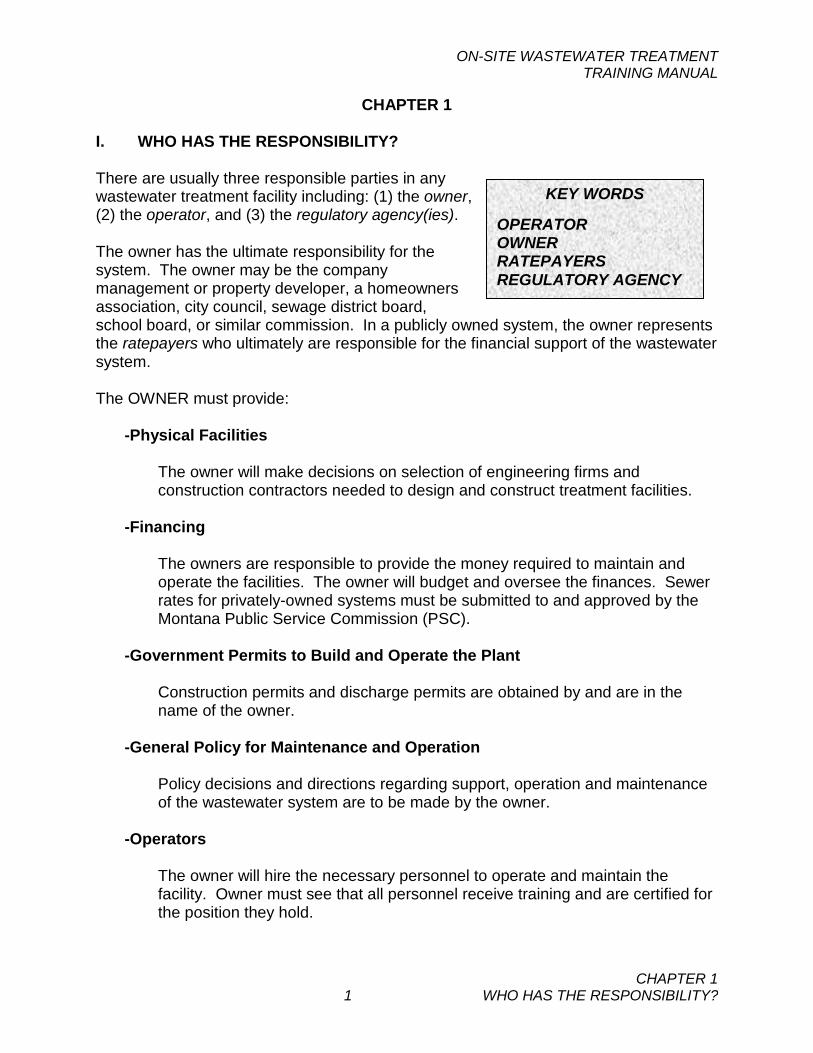
CHAPTER 1 I. WHO HAS THE RESPONSIBILITY? There are usually three responsible parties in any wastewater treatment facility including: (1) the owner, (2) the operator, and (3) the regulatory agency(ies). The owner has the ultimate responsibility for the system. The owner may be the company management or property developer, a homeowners association, city council, sewage district board, school board, or similar commission. In a publicly owned system, the owner represents the ratepayers who ultimately are responsible for the financial support of the wastewater system. The OWNER must provide:
-Physical Facilities
The owner will make decisions on selection of engineering firms and construction contractors needed to design and construct treatment facilities.
-Financing
The owners are responsible to provide the money required to maintain and operate the facilities. The owner will budget and oversee the finances. Sewer rates for privately-owned systems must be submitted to and approved by the Montana Public Service Commission (PSC).
-Government Permits to Build and Operate the Plant
Construction permits and discharge permits are obtained by and are in the name of the owner.
-General Policy for Maintenance and Operation
Policy decisions and directions regarding support, operation and maintenance of the wastewater system are to be made by the owner.
-Operators
The owner will hire the necessary personnel to operate and maintain the facility. Owner must see that all personnel receive training and are certified for the position they hold.
KEY WORDS OPERATOR OWNER RATEPAYERS REGULATORY AGENCY
ON-SITE WASTEWATER TREATMENT TRAINING MANUAL
CHAPTER 1 2 WHO HAS THE RESPONSIBILITY?
The OPERATOR is responsible to the OWNER for:
-Certification
The operator must apply for and pass certification tests as the operator in responsible charge, at the appropriate classification level. To maintain certification, the operator must obtain continuing education through attendance of classes or other forms of training. The operator must also maintain their license through payment of the annual renewal fee.
-Facilities Operation
The operator is responsible for all operational work at the treatment facility which might include process control testing, compliance monitoring, supervision, scheduling, trend charting, general record keeping and many other aspects required for good plant operation.
-Record Keeping
The operator must be familiar with the discharge permit requirements and work to ensure that the treatment system complies with applicable state and federal laws. He/she must keep proper records of operation and must know how to interpret his records.
-Sampling and Testing
The operator must be able to obtain good representative samples for laboratory testing. The operator should understand the significance of the results of the testing and be able to utilize the results in operation of the plant.
-Reporting
The operator must prepare reports and see that they are submitted on time.
-Maintenance of the Plant.
The buildings, equipment, treatment structures and grounds must be kept in good repair.
-Continued Training
The operator must continue to keep informed on subjects relating to wastewater treatment and water quality.
ON-SITE WASTEWATER TREATMENT TRAINING MANUAL
CHAPTER 1 3 WHO HAS THE RESPONSIBILITY?
-Information to the owner
The operator should prepare an annual budget for owner approval, attend meetings and report on matters concerning wastewater treatment.
The REGULATORY AGENCIES are responsible for seeing that wastewater facilities are constructed and operated in accordance with the laws and regulations protecting water quality in our state and our nation. Similar to the owner, the regulatory agencies represent the public including the local ratepayers, the taxpayer and the public in general. Owners must meet the requirements of federal, state and local agencies.
-The US Environmental Protection Agency (EPA) is responsible to Congress for the Federal Clean Water Act. EPA administers this Federal law as well as any necessary enforcement to prevent pollution of the waters of the nation. However, many of the legal requirements of these Federal laws have been delegated by EPA to the State of Montana for administration.
-The Montana Department of Environmental Quality (DEQ) is the State agency charged with the responsibility of enforcing water quality based regulatory requirements in Montana, including administration of Montana’s version of the Federal Clean Water Act, the Montana Water Quality Act. -Local departments or board of health in Montana have their own regulations for on-site wastewater treatment systems that cannot be less stringent than state standards. These regulations generally include a review and approval process.
Questions and matters of regulation and certification should be directed to the following DEQ programs:
Discharge Permits - Water Protection Bureau, ph (406) 444-3080 Operator Certification - Operator Certification Program, ph (406) 444-4400 Construction - Public Water Supply Program, ph (406) 444-4400 Funding - Technical and Financial Assistance Bureau, ph (406) 444-6697 Be sure to also contact the county or city-county department of health regarding local requirements. Requirements will vary.
In addition to the above regulatory programs at DEQ, the Montana PSC also regulates privately-owned systems. The PSC ensures that sewer rates are reasonable based upon actual construction, operation and maintenance costs. Annual reports must also be filed with the PSC. Questions should be directed to the PSC in Helena at (406) 444-6199. Regulatory requirements are discussed in more detail in Chapter 5 of this Manual.
ON-SITE WASTEWATER TREATMENT TRAINING MANUAL
CHAPTER 1 4 WHO HAS THE RESPONSIBILITY?
SELF-STUDY QUESTIONS - CHAPTER 1 1. The money to operate and maintain a wastewater treatment plant is supplied by:
(a) The State Department of Environmental Quality (b) An EPA grant (c) Local ratepayers (d) All of the above
2. The operator is required to:
(a) Do the daily operation and maintenance (b) Do the required sampling and testing (c) Prepare reports and keep records. (d) All of the above
3. The Regulatory Agency responsible for seeing that operations and discharge quality
are in accordance with the Montana Pollutant Discharge Elimination System (MPDES) and Montana Groundwater Pollution Control System (MGWPCS) is:
(a) The Montana Department of Natural Resources (b) Montana Department of Environmental Quality (c) The County Health Department (d) The EPA
4. If an on-site system is not performing properly and the discharge water is not of
good quality, who has the ultimate responsibility to correct problems?
(a) The engineer who designed the plant (b) The DEQ (c) The operator in charge (d) The owner of the facility
ON-SITE WASTEWATER TREATMENT TRAINING MANUAL
CHAPTER 2 1 WHAT IS WASTEWATER?
CHAPTER 2 I. WHAT IS WASTEWATER? Most of us think of wastewater in terms of our domestic usage. The dishwater that we dump down the drain, our shower water and the stuff that goes down the toilet when we flush it. But an experienced sewage collection system or treatment plant operator will tell you that it can be highly variable in both quantity and characteristics. Wastewater can be made up of primarily domestic waste that comes from the home and, in small communities this is the predominant characteristic. It also can carry industrial and commercial wastes - such as the waste from a car wash containing a lot of dirt and grit, or the fast food restaurant that releases fats and grease. Wastewater often picks up groundwater through leaks in the collection system or stormwater discharged through roof drains. There may be a dairy or food processing operation that releases strong waste material periodically. Toxic compounds can be illegally discharged into a sewer system. Each different source adds differing wastes in quality and quantity. A summary of the general categories of wastewater might include:
1. Domestic waste that contains human wastes and general household wastewater.
2. Commercial waste that originates from office buildings, schools, churches restaurants and other small businesses.
3. Industrial waste that originates from manufacturing or processing operations. Wastes from animal confinement facilities and slaughterhouses could be included. (Industrial wastes are not commonly discharged to on-site systems).
4. Storm water and surface runoff is clear water originating from rain or snow on streets, roof drains, or sump pumps and is sometimes called inflow. These sources should be excluded to the maximum extent possible in on-site systems.
5. Groundwater infiltration. Pipe joints and cracks can allow leakage or infiltration into the pipe and if the groundwater table is high. This should be excluded to the maximum extent possible.
6. Illegal discharges. A wide variety of pollutants can be carried into surface and groundwaters by illegal discharges to a sewer system. These may be intentionally or unknowingly discharged. The consequences of illegal discharge can be severe. Proper disposal of chemicals, oils and solid wastes is
KEY WORDS AMMONIFICATION BIOCHEMICAL OXYGEN DEMAND DENITRIFICATION DISSOLVED SOLIDS INFILTRATION INORGANIC NITRIFICATION NITROGEN CYCLE ORGANIC pH SEPTAGE SEPTIC SETTLEABLE SOLIDS SEWER USE ORDINANCE STORMWATER SUSPENDED SOLIDS TOTAL SUSPENDED SOLIDS
ON-SITE WASTEWATER TREATMENT TRAINING MANUAL
CHAPTER 2 2 WHAT IS WASTEWATER?
necessary to prevent serious water pollution. Sewer use ordinances are local regulations adopted by communities to control the discharge of wastes.
It is the material carried in the wastewater that concerns the wastewater treatment plant operator. These materials can be dissolved, suspended or settleable solids. If a solid is held on a laboratory filter, it is considered a suspended solid. If it passes through the lab filter, it is a dissolved solid. Some solids coming down the sewer are heavy enough that they settle out easily in the septic tank. These are called settleable solids. Effluent filters are often used at the discharge from septic tanks to reduce solids loading to subsequent treatment processes. The treatment of wastewater is a process for converting undesirable dissolved, suspended and settleable solids into stable and acceptable forms. Typical domestic wastewater consists of less than 0.1% solids carried in the water, but these impurities can do serious harm to the receiving water. There are two broad classifications of these wastewater substances: organic and inorganic. Organic materials are of plant or animal origin. Inorganic materials are of mineral origin without carbon compounds. In septic tank treatment systems, most inorganic materials are easily handled if the size of the tank has been appropriately designed for the accumulation of solids. Grit and heavier solids settle readily when they enter a septic tank where the velocity of the water becomes very slow. The organic materials in wastewater are much more varied and complex than the inorganic materials. The organic materials are more difficult to handle since they don’t always settle readily and are often dissolved. Where mechanical treatment is provided in advance of the drainfield, many of these dissolved materials can be converted into solids and removed from the flow stream prior to discharge into the drainfield. Mechanical treatment plants will typically use concrete basins or clarifiers to remove settleable solids. Mechanical treatment plant clarifiers cannot store solids for extended periods of time and the solids must be removed from the system on a daily basis. In less complex systems such as a simple septic tank and drainfield system, proper monitoring and pumping of the septic tank is a critical factor in minimizing impacts of solids on the drainfield. Solids removal may not be necessary for several years or longer from a septic tank, but regular checks are still necessary. Effluent filters are an effective barrier against suspended solids leaving the septic tank, but they do require periodic cleaning. The septic tank sludge, or septage, and screened solids removed from on-site treatment systems may require additional stabilization before they can be landfilled or land applied. The regulatory requirements for disposal of the solids are discussed in Chapter 4 of this manual. Flow and Load Variations -The composition and the quantity of wastewater varies constantly all day and all night. As you might expect, water use normally drops dramatically during the night and by 5 or 6 AM has reached the low point of the day. As people wake, shower, wash, cook and start the day's activities, wastewater flow rapidly
ON-SITE WASTEWATER TREATMENT TRAINING MANUAL
CHAPTER 2 3 WHAT IS WASTEWATER?
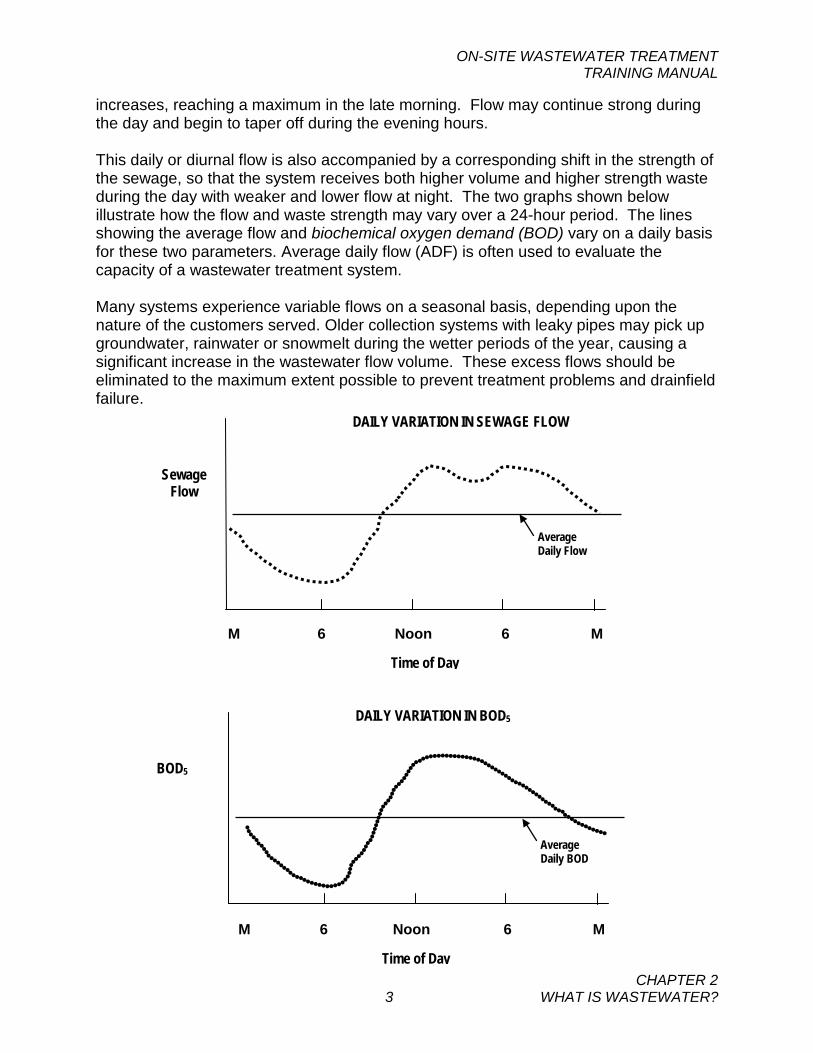
increases, reaching a maximum in the late morning. Flow may continue strong during the day and begin to taper off during the evening hours. This daily or diurnal flow is also accompanied by a corresponding shift in the strength of the sewage, so that the system receives both higher volume and higher strength waste during the day with weaker and lower flow at night. The two graphs shown below illustrate how the flow and waste strength may vary over a 24-hour period. The lines showing the average flow and biochemical oxygen demand (BOD) vary on a daily basis for these two parameters. Average daily flow (ADF) is often used to evaluate the capacity of a wastewater treatment system. Many systems experience variable flows on a seasonal basis, depending upon the nature of the customers served. Older collection systems with leaky pipes may pick up groundwater, rainwater or snowmelt during the wetter periods of the year, causing a significant increase in the wastewater flow volume. These excess flows should be eliminated to the maximum extent possible to prevent treatment problems and drainfield failure.
BOD5
Average Daily BOD
DAILY VARIATION IN BOD5
M 6 Noon 6 M
Time of Day
Sewage Flow
Average Daily Flow
DAILY VARIATION IN SEWAGE FLOW
M 6 Noon 6 M
Time of Day
ON-SITE WASTEWATER TREATMENT TRAINING MANUAL
CHAPTER 2 4 WHAT IS WASTEWATER?
Treatment facilities must be designed to handle these high flow events to produce an acceptable level of treatment, prior to discharge. Fresh domestic sewage is typically gray-colored water, not unlike the appearance of dirty dishwater. It has a musty, but not highly objectionable, odor. If sewage is not fresh or has been in the collection system for a long time, it can turn septic. Septic sewage is black with a strong foul odor and is devoid of oxygen. Even though septic tanks are designed to work under septic conditions, it is important to avoid septic conditions in the wastewater collection system prior to the septic tank because nuisance odor conditions can develop.
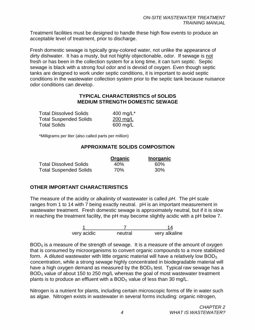
TYPICAL CHARACTERISTICS of SOLIDS MEDIUM STRENGTH DOMESTIC SEWAGE
Total Dissolved Solids 400 mg/L* Total Suspended Solids 200 mg/L Total Solids 600 mg/L *Milligrams per liter (also called parts per million)
APPROXIMATE SOLIDS COMPOSITION
Organic Inorganic
Total Dissolved Solids 40% 60% Total Suspended Solids 70% 30%
OTHER IMPORTANT CHARACTERISTICS The measure of the acidity or alkalinity of wastewater is called pH. The pH scale ranges from 1 to 14 with 7 being exactly neutral. pH is an important measurement in wastewater treatment. Fresh domestic sewage is approximately neutral, but if it is slow in reaching the treatment facility, the pH may become slightly acidic with a pH below 7.
1 7 14 very acidic neutral very alkaline
BOD5 is a measure of the strength of sewage. It is a measure of the amount of oxygen that is consumed by microorganisms to convert organic compounds to a more stabilized form. A diluted wastewater with little organic material will have a relatively low BOD5 concentration, while a strong sewage highly concentrated in biodegradable material will have a high oxygen demand as measured by the BOD5 test. Typical raw sewage has a BOD5 value of about 150 to 250 mg/L whereas the goal of most wastewater treatment plants is to produce an effluent with a BOD5 value of less than 30 mg/L. Nitrogen is a nutrient for plants, including certain microscopic forms of life in water such as algae. Nitrogen exists in wastewater in several forms including: organic nitrogen,
ON-SITE WASTEWATER TREATMENT TRAINING MANUAL
CHAPTER 2 5 WHAT IS WASTEWATER?
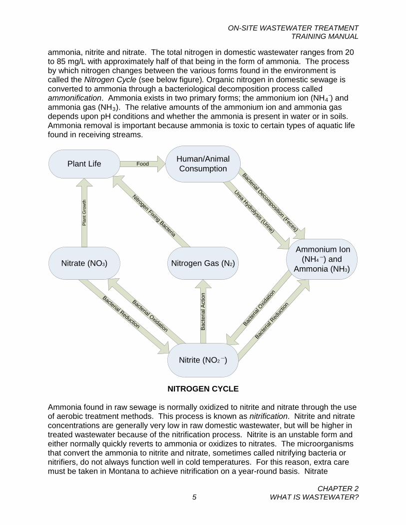
ammonia, nitrite and nitrate. The total nitrogen in domestic wastewater ranges from 20 to 85 mg/L with approximately half of that being in the form of ammonia. The process by which nitrogen changes between the various forms found in the environment is called the Nitrogen Cycle (see below figure). Organic nitrogen in domestic sewage is converted to ammonia through a bacteriological decomposition process called ammonification. Ammonia exists in two primary forms; the ammonium ion (NH4
-) and ammonia gas (NH3). The relative amounts of the ammonium ion and ammonia gas depends upon pH conditions and whether the ammonia is present in water or in soils. Ammonia removal is important because ammonia is toxic to certain types of aquatic life found in receiving streams.
Pla
nt G
row
th
Nitrogen Fixing Bacteria
Bacterial Reduction
Bacterial Oxidation
Bacter
ial R
educ
tion
Bacter
ial O
xidati
on
Bacterial Decomposition (Feces)
Urea Hydrolysis (Urine)
Human/Animal Consumption
Ammonium Ion (NH4 ¯) and
Ammonia (NH3)
Nitrite (NO2 ¯)
Nitrate (NO3) Nitrogen Gas (N2)
Bac
teria
l Act
ion
Plant Life Food
NITROGEN CYCLE Ammonia found in raw sewage is normally oxidized to nitrite and nitrate through the use of aerobic treatment methods. This process is known as nitrification. Nitrite and nitrate concentrations are generally very low in raw domestic wastewater, but will be higher in treated wastewater because of the nitrification process. Nitrite is an unstable form and either normally quickly reverts to ammonia or oxidizes to nitrates. The microorganisms that convert the ammonia to nitrite and nitrate, sometimes called nitrifying bacteria or nitrifiers, do not always function well in cold temperatures. For this reason, extra care must be taken in Montana to achieve nitrification on a year-round basis. Nitrate
ON-SITE WASTEWATER TREATMENT TRAINING MANUAL
CHAPTER 2 6 WHAT IS WASTEWATER?
discharged to a receiving stream may stimulate the growth of undesirable plants or algae, adversely affecting water quality. Nitrate that is discharged from a septic system drainfield can enter the groundwater, posing a drinking water risk to infants less than six months in age.
Additional specialized processes can be incorporated into on-site treatment systems to significantly reduce the nitrate concentration of the treated sewage. This process is called denitrification and is achieved by converting nitrate to nitrogen gas under low oxygen conditions. As with nitrification, denitrification is a sensitive process and must be carefully designed and operated to work successfully in cold climates.
Phosphorus is present in domestic wastewater in concentrations ranging from 6 to 20 mg/L, most of which is inorganic phosphorus. Phosphorus is essential to the life processes of microorganisms but may also stimulate the growth of undesirable plant species in a receiving stream. As an example, dense filamentous growth of algae is sometimes observed in the Clark Fork River. Studies have shown that this plant growth is caused in part by phosphorous discharged from wastewater treatment plants. Some communities have also instituted a ban on phosphorus in detergents to reduce the amount of phosphorous that enters wastewater systems.
Other sources of phosphorus, such as septic systems, are also subject to restrictions to lower the discharge of nutrients. Often a basin-wide approach to controlling nutrients is the most effective means to improve and preserve water quality in an impacted stream. Every one needs to do their part in keeping Montana’s high quality waters clean. II. WASTEWATER ANALYSIS BOD – As discussed, BOD stands for Biochemical Oxygen Demand. We know that bacteria consume waste as a food supply for growth and the bacteria use oxygen to perform this task. These facts are the basis for measurement of the "strength" of the wastewater. In the BOD test, a measured sample of wastewater is put into a bottle of dilution water that contains dissolved oxygen. After five days of incubation at constant temperature of 20 °C (68°F) and no light, the amount of dissolved oxygen consumed is determined. Five days is the standard test period, although for special purposes other periods may be used. The number of milligrams of oxygen that has been consumed, calculated as if one liter of sample had been used, is recorded as the BOD. BOD is often written as BOD5. The subscript 5 means that the test was a 5-day test. When the test is performed on raw sewage, it is a measure of the "strength" of the wastewater. When the BOD test is performed on the discharge water, it is a measure of the oxygen demand that may be placed upon the receiving water. Normal domestic sewage will have a BOD5 concentration of 150 to 250 mg/L but local conditions may create much higher (or lower) test results. If the sewer collection system allows the infiltration of a lot of groundwater or collects storm water, the sewage may be weak and have a low BOD concentration. There may be sources of strong wastewater such as a restaurant. If these systems discharge to the system, the high
ON-SITE WASTEWATER TREATMENT TRAINING MANUAL
CHAPTER 2 7 WHAT IS WASTEWATER?
strength waste may upset the treatment process. Typically, a figure of 0.17 to 0.22 pounds of BOD5 is contributed every day to the sewage system by each person in a community. Total Suspended Solids (TSS) – The test for total suspended solids is run by filtering a measured amount of water through a standard membrane filter that has been carefully weighed. After filtering, the filter membrane is again weighed and the difference in weight is calculated to the number of milligrams of TSS per liter of water. Nutrients – It is common for wastewater systems to be required to test the wastewater discharge for nitrogen and phosphorous. Smaller systems will normally send samples to the State or a private lab to perform the analyses. Nutrients may be limited in the discharge permit to address a water quality standard or public health concern. Additionally, the total annual load of nutrients may be limited on a discharging system to comply with the nondegradation provisions of the Montana Water Quality Act. For these reasons, operators must collect samples in a proper manner for analysis. Other Parameters – Other parameters are also often required for permit monitoring. See Chapter 5 for regulatory requirements, including permit monitoring, and Chapter 6 for sampling procedures.
ON-SITE WASTEWATER TREATMENT TRAINING MANUAL
CHAPTER 2 8 WHAT IS WASTEWATER?
SELF-STUDY QUESTIONS - CHAPTER 2 1. The time of day when you would expect the lowest sewage flow rate is:
(a) About midnight (b) About 3 to 4 PM (c) About 5 to 6 AM (d) Flow is nearly constant all day and night.
2. The solids that most easily drop out of wastewater are:
(a) Organic solids of human origin (b) Solids that come from infiltration (c) Dissolved solids (d) Inorganic Grit
3. Infiltration water is:
(a) Groundwater that leaks into the sewer (b) Storm runoff water (c) Industrial wastewater (d) The treated water from a third cell
4. Of the total solids content of domestic sewage, approximately what proportion are
dissolved solids?
(a) One third (b) 100% (c) Two thirds (d) There are no dissolved solids.
5. BOD is an acronym for Biochemical Oxygen Demand. The unit of measurement is:
(a) Pounds of oxygen per acre (b) Grams of oxygen per liter (c) Milligrams of sewage per milliliter (d) Milligrams of oxygen used per liter
6. Typical domestic sewage will have a BOD5 of about:
(a) 150 to 250 milligrams per liter (b) 80 milligrams per liter (c) 20 milligrams per liter (d) 0.17 milligrams per liter
ON-SITE WASTEWATER TREATMENT TRAINING MANUAL
CHAPTER 3 1 ON-SITE TREATMENT SYSTEMS
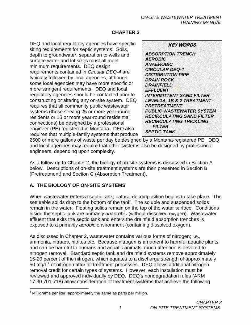
CHAPTER 3 DEQ and local regulatory agencies have specific siting requirements for septic systems. Soils, depth to groundwater, separation to wells and surface water and lot sizes must all meet minimum requirements. DEQ design requirements contained in Circular DEQ-4 are typically followed by local agencies, although some local agencies may have more specific or more stringent requirements. DEQ and local regulatory agencies should be contacted prior to constructing or altering any on-site system. DEQ requires that all community public wastewater systems (those serving 25 or more year-round residents or 15 or more year-round residential connections) be designed by a professional engineer (PE) registered in Montana. DEQ also requires that multiple-family systems that produce 2500 or more gallons of waste per day be designed by a Montana-registered PE. DEQ and local agencies may require that other systems also be designed by professional engineers, depending upon complexity. As a follow-up to Chapter 2, the biology of on-site systems is discussed in Section A below. Descriptions of on-site treatment systems are then presented in Section B (Pretreatment) and Section C (Absorption Treatment). A. THE BIOLOGY OF ON-SITE SYSTEMS When wastewater enters a septic tank, natural decomposition begins to take place. The settleable solids drop to the bottom of the tank. The soluble and suspended solids remain in the water. Floating solids remain on the top of the water surface. Conditions inside the septic tank are primarily anaerobic (without dissolved oxygen). Wastewater effluent that exits the septic tank and enters the drainfield absorption trenches is exposed to a primarily aerobic environment (containing dissolved oxygen). As discussed in Chapter 2, wastewater contains various forms of nitrogen; i.e., ammonia, nitrates, nitrites etc. Because nitrogen is a nutrient to harmful aquatic plants and can be harmful to humans and aquatic animals, much attention is devoted to nitrogen removal. Standard septic tank and drainfield systems remove approximately 15-20 percent of the nitrogen, which equates to a discharge strength of approximately 50 mg/L1 of nitrogen after all treatment processes. DEQ allows additional nitrogen removal credit for certain types of systems. However, each installation must be reviewed and approved individually by DEQ. DEQ’s nondegradation rules (ARM 17.30.701-718) allow consideration of treatment systems that achieve the following 1 Milligrams per liter; approximately the same as parts per million.
KEY WORDS
ABSORPTION TRENCH AEROBIC ANAEROBIC CIRCULAR DEQ-4 DISTRIBUTION PIPE DRAIN ROCK DRAINFIELD EFFLUENT INTERMITTENT SAND FILTER LEVEL1A, 1B & 2 TREATMENT PRETREATMENT PUBLIC WASTEWATER SYSTEM RECIRCULATING SAND FILTER RECIRCULATING TRICKLING
FILTER SEPTIC TANK
ON-SITE WASTEWATER TREATMENT TRAINING MANUAL
CHAPTER 3 2 ON-SITE TREATMENT SYSTEMS
removals of nitrogen:
• Level 1b – Achieves a nitrogen discharge of approximately 40 mg/L • Level 1a – Achieves a nitrogen discharge of approximately 30 mg/L • Level 2 – Achieves a nitrogen discharge of approximately 24 mg/L
These systems consist of a specialized treatment process(es) beyond the standard septic tank and drainfield system. For example, systems with recirculating sand or trickling filters may receive credit for higher nitrogen removal under certain design and operating conditions. Systems that include more complicated mechanical processes, such as sequencing batch reactors, may also receive additional credit. Microorganisms, which are plant and animal life too small to be seen without a microscope, perform the wastewater decomposition processes and often do it in a cooperative way. Below are descriptions of the primary microorganisms in the decomposition (or stabilization) process: Viruses Viruses are the simplest of life forms and are very small; about one one-hundredth the size of a typical bacterium cell. An electron microscope is normally needed to see viruses. Wastewater typically contains abundant viruses, many of which can cause diseases in man and animals. Viruses do not contribute directly to the wastewater treatment process, but they provide a food source for bacteria and higher life forms that do provide treatment. Viruses are therefore partially removed by other microorganisms during the treatment process. Viruses also are removed by settling in the septic tank and by adsorption on fine-grained soil particles beneath adsorption trenches. Because some viruses are not removed by soils and can travel long distances in groundwater, it is important that the minimum regulatory siting and set-back distances be observed. Bacteria Bacteria are the most important microorganisms in wastewater treatment. Bacteria range in size and shape, but are generally several microns or smaller in size. There are 25,000 microns in an inch, so a standard microscope is needed to view bacteria. For most types of organic material, there generally is a form of bacteria that will utilize it for food to obtain energy and to generate new bacterial cells. There are bacteria that will use the waste that comes down the sewer as a food supply. There are thousands of varieties of bacteria and an on-site treatment system will contain billions upon billions of them. They perform valuable service in wastewater treatment and society is in their debt for taking on an unpleasant task. Bacteria can be classified into three types: • Anaerobic bacteria (anaerobes) live in septic tanks and do not need dissolved
oxygen to survive. Some will reduce oxygen-containing compounds, such as
ON-SITE WASTEWATER TREATMENT TRAINING MANUAL
CHAPTER 3 3 ON-SITE TREATMENT SYSTEMS
sulfates. One of the byproducts of this decomposition is hydrogen sulfide. Byproduct gases produce strong odors and are even toxic in higher concentrations. Hydrogen sulfide often escapes into the air and is vented from the septic tank through the building vent. Anaerobic bacteria also partially digest proteins by converting them to volatile fatty acids. Overall, the preliminary treatment provided by a septic tank reduces the raw wastewater BOD by 30-50 percent by removing settleable and floating solids and providing partial anaerobic digestion of organic material.
• Facultative bacteria can live and work with or without free oxygen present. Facultative bacteria can live in the septic tank and their role in treatment is considered to be similar to the anaerobes. Certain facultative aerobes will help to remove nitrogen from wastewater; i.e., denitrifying bacteria. Level 1b, 1a and 2 systems that are approved by DEQ for additional nitrogen removal beyond the standard septic system are designed to create favorable living conditions for denitrifying bacteria.
• Aerobic bacteria (aerobes) live where there is free (dissolved) oxygen available to them. These aerobes live and assist in the treatment of wastewater after preliminary treatment by the septic tank. Aerobes provide significant reductions in the carbonaceous (organic) content of septic tank effluent. This breakdown occurs in ISFs, RSFs, RTFs and in drainfield absorption trenches in the “biomat” layer that develops near the bottom of the absorption trench. The biomat layer is approximately one inch thick.
Beneath the biomat layer, nitrifying aerobes convert much of the remaining ammonia to nitrites and nitrates (nitrification). As discussed earlier, nitrification also will occur in the filters if ISF, RSF or RTF treatment is provided. Unfortunately, nitrites and nitrates are not adsorbed by the soil and will ultimately be carried into groundwater as effluent continues to migrate downward. However, much of the phosphorus and remaining living bacteria are adsorbed onto soil particles as the effluent infiltrates further into the soil profile. Phosphorus is not effectively removed otherwise by on-site systems unless specialized additional treatment is provided. As with viruses, it is important that minimum siting and set-back distances be observed since not all bacteria are removed by the soil. Algae Algae are microscopic single cell or multiple cell plants that may accumulate at times on surface water. Algae, like other green plants, contain chlorophyll and can perform the process of photosynthesis. This process, which requires sunlight, consumes carbon dioxide and releases free oxygen. Because on-site treatment processes are seldom open to the sunlight in Montana, algae are not considered an important factor in the treatment process.
ON-SITE WASTEWATER TREATMENT TRAINING MANUAL
CHAPTER 3 4 ON-SITE TREATMENT SYSTEMS
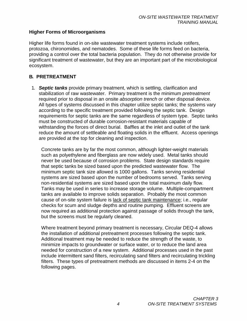
Higher Forms of Microorganisms Higher life forms found in on-site wastewater treatment systems include rotifers, protozoa, chironomides, and nematodes. Some of these life forms feed on bacteria, providing a control over the total bacteria population. They do not otherwise provide for significant treatment of wastewater, but they are an important part of the microbiological ecosystem. B. PRETREATMENT 1. Septic tanks provide primary treatment, which is settling, clarification and
stabilization of raw wastewater. Primary treatment is the minimum pretreatment required prior to disposal in an onsite absorption trench or other disposal device. All types of systems discussed in this chapter utilize septic tanks; the systems vary according to the specific treatment provided following the septic tank. Design requirements for septic tanks are the same regardless of system type. Septic tanks must be constructed of durable corrosion-resistant materials capable of withstanding the forces of direct burial. Baffles at the inlet and outlet of the tank reduce the amount of settleable and floating solids in the effluent. Access openings are provided at the top for cleaning and inspection. Concrete tanks are by far the most common, although lighter-weight materials such as polyethylene and fiberglass are now widely used. Metal tanks should never be used because of corrosion problems. State design standards require that septic tanks be sized based upon the predicted wastewater flow. The minimum septic tank size allowed is 1000 gallons. Tanks serving residential systems are sized based upon the number of bedrooms served. Tanks serving non-residential systems are sized based upon the total maximum daily flow. Tanks may be used in series to increase storage volume. Multiple-compartment tanks are available to improve solids separation. Probably the most common cause of on-site system failure is lack of septic tank maintenance; i.e., regular checks for scum and sludge depths and routine pumping. Effluent screens are now required as additional protection against passage of solids through the tank, but the screens must be regularly cleaned. Where treatment beyond primary treatment is necessary, Circular DEQ-4 allows the installation of additional pretreatment processes following the septic tank. Additional treatment may be needed to reduce the strength of the waste, to minimize impacts to groundwater or surface water, or to reduce the land area needed for construction of a new system. Additional processes used in the past include intermittent sand filters, recirculating sand filters and recirculating trickling filters. These types of pretreatment methods are discussed in items 2-4 on the following pages.
ON-SITE WASTEWATER TREATMENT TRAINING MANUAL
CHAPTER 3 5 ON-SITE TREATMENT SYSTEMS
Basic One-Compartment Septic Tank
Source: EPA, 2002. NOTE: Systems using aerobic treatment units in lieu of septic tanks are not discussed in this manual. Please see Circular DEQ-4, Section 1.2 (Montana DEQ) and “Onsite Wastewater Treatment Systems Manual” (U.S. EPA 2002, EPA/625/R-00/008) for additional information regarding the general types of on-site systems and their applications. Please refer to “Operation of Wastewater Treatment Plants, Volumes I & II”, California State University for more information regarding operation of mechanical aerobic treatment units. 2. Intermittent sand filters (ISFs) have been used in the past for small systems
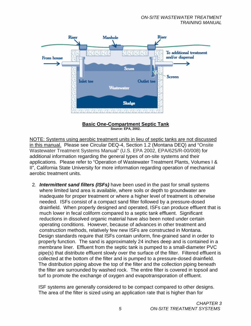
where limited land area is available, where soils or depth to groundwater are inadequate for proper treatment or where a higher level of treatment is otherwise needed. ISFs consist of a compact sand filter followed by a pressure-dosed drainfield. When properly designed and operated, ISFs can produce effluent that is much lower in fecal coliform compared to a septic tank effluent. Significant reductions in dissolved organic material have also been noted under certain operating conditions. However, because of advances in other treatment and construction methods, relatively few new ISFs are constructed in Montana. Design standards require that ISFs contain uniform, fine-grained sand in order to properly function. The sand is approximately 24 inches deep and is contained in a membrane liner. Effluent from the septic tank is pumped to a small-diameter PVC pipe(s) that distribute effluent slowly over the surface of the filter. Filtered effluent is collected at the bottom of the filter and is pumped to a pressure-dosed drainfield. The distribution piping above the top of the filter and the collection piping beneath the filter are surrounded by washed rock. The entire filter is covered in topsoil and turf to promote the exchange of oxygen and evapotransporation of effluent. ISF systems are generally considered to be compact compared to other designs. The area of the filter is sized using an application rate that is higher than for
ON-SITE WASTEWATER TREATMENT TRAINING MANUAL
CHAPTER 3 6 ON-SITE TREATMENT SYSTEMS
standard absorption trenches. Also, the filter is constructed as a bed rather than in trenches. Because ISFs can be effective at reducing the dissolved organic content of wastewater, the required absorption area in the drainfield can be downsized by 25-50 percent, depending upon soil conditions.
Intermittent (Single-Pass) Sand Filter System Schematic Source: State of Rhode Island, 2010.
Intermittent (Single-Pass) Sand Filter Cross-Section Source: King County (WA) Health Services, 2010.
ON-SITE WASTEWATER TREATMENT TRAINING MANUAL
CHAPTER 3 7 ON-SITE TREATMENT SYSTEMS
Significant nitrification by aerobic bacteria (conversion of ammonia to nitrites and nitrates) typically occurs within the filter. ISFs are also very effective in removing E. Coli bacteria, a common disease-causing bacteria present in sewage. ISFs can potentially be used to reduce the amount of nitrates, although this requires the addition of a supplemental carbon food source for denitrifying microbes in the filter. Using an ISF for denitrification is rare in Montana.
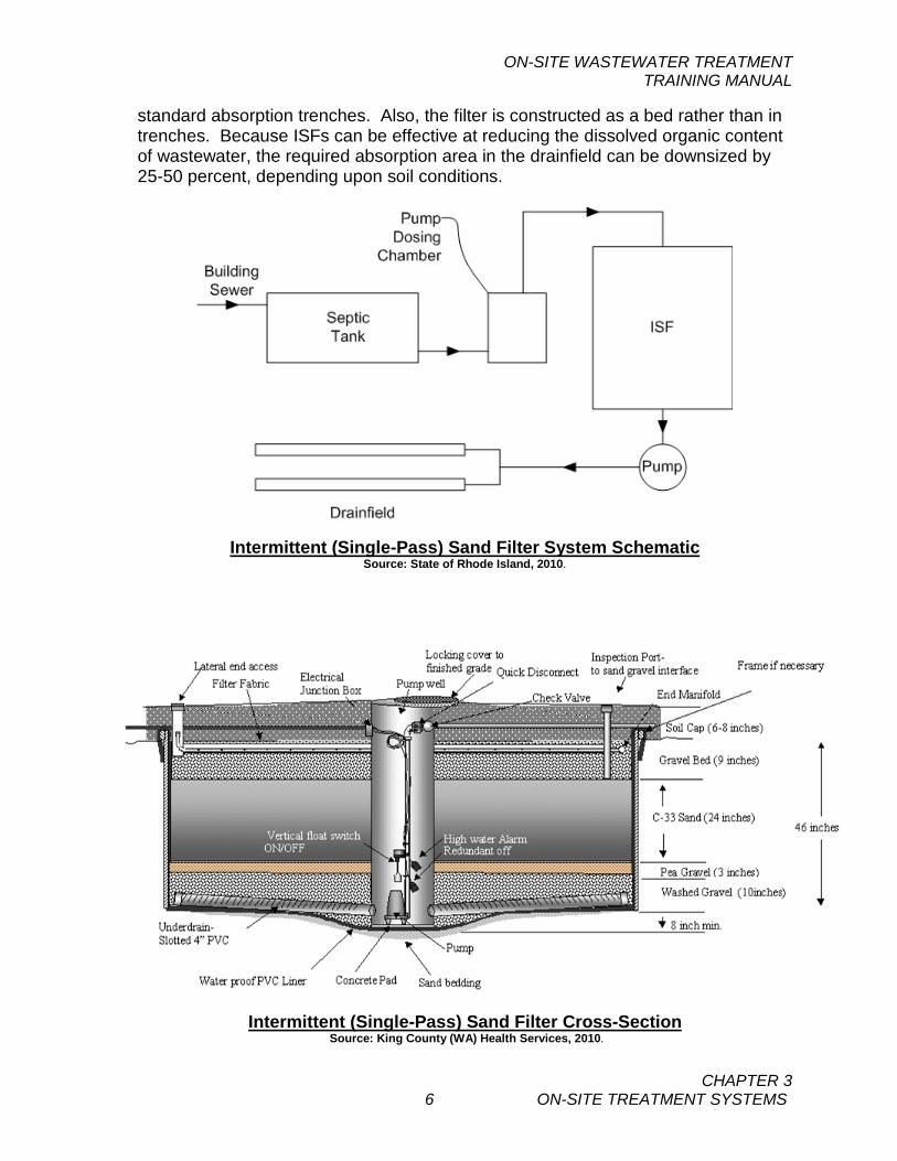
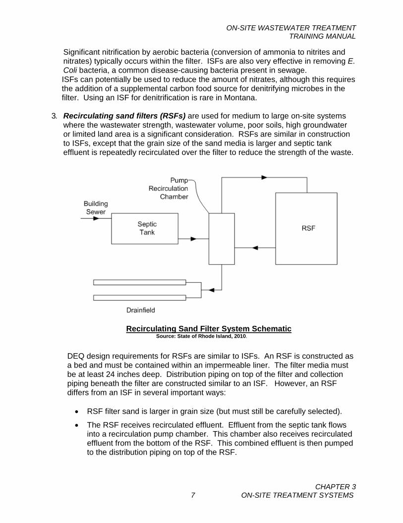
3. Recirculating sand filters (RSFs) are used for medium to large on-site systems where the wastewater strength, wastewater volume, poor soils, high groundwater or limited land area is a significant consideration. RSFs are similar in construction to ISFs, except that the grain size of the sand media is larger and septic tank effluent is repeatedly recirculated over the filter to reduce the strength of the waste.
Recirculating Sand Filter System Schematic Source: State of Rhode Island, 2010.
DEQ design requirements for RSFs are similar to ISFs. An RSF is constructed as a bed and must be contained within an impermeable liner. The filter media must be at least 24 inches deep. Distribution piping on top of the filter and collection piping beneath the filter are constructed similar to an ISF. However, an RSF differs from an ISF in several important ways:
• RSF filter sand is larger in grain size (but must still be carefully selected).
• The RSF receives recirculated effluent. Effluent from the septic tank flows into a recirculation pump chamber. This chamber also receives recirculated effluent from the bottom of the RSF. This combined effluent is then pumped to the distribution piping on top of the RSF.
ON-SITE WASTEWATER TREATMENT TRAINING MANUAL
CHAPTER 3 8 ON-SITE TREATMENT SYSTEMS
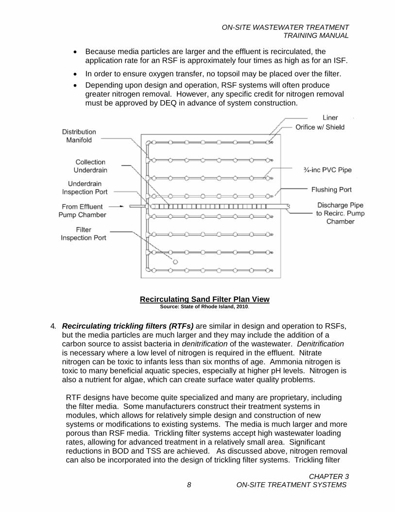
• Because media particles are larger and the effluent is recirculated, the application rate for an RSF is approximately four times as high as for an ISF.
• In order to ensure oxygen transfer, no topsoil may be placed over the filter. • Depending upon design and operation, RSF systems will often produce
greater nitrogen removal. However, any specific credit for nitrogen removal must be approved by DEQ in advance of system construction.
Recirculating Sand Filter Plan View Source: State of Rhode Island, 2010.
4. Recirculating trickling filters (RTFs) are similar in design and operation to RSFs, but the media particles are much larger and they may include the addition of a carbon source to assist bacteria in denitrification of the wastewater. Denitrification is necessary where a low level of nitrogen is required in the effluent. Nitrate nitrogen can be toxic to infants less than six months of age. Ammonia nitrogen is toxic to many beneficial aquatic species, especially at higher pH levels. Nitrogen is also a nutrient for algae, which can create surface water quality problems.
RTF designs have become quite specialized and many are proprietary, including the filter media. Some manufacturers construct their treatment systems in modules, which allows for relatively simple design and construction of new systems or modifications to existing systems. The media is much larger and more porous than RSF media. Trickling filter systems accept high wastewater loading rates, allowing for advanced treatment in a relatively small area. Significant reductions in BOD and TSS are achieved. As discussed above, nitrogen removal can also be incorporated into the design of trickling filter systems. Trickling filter
ON-SITE WASTEWATER TREATMENT TRAINING MANUAL
CHAPTER 3 9 ON-SITE TREATMENT SYSTEMS
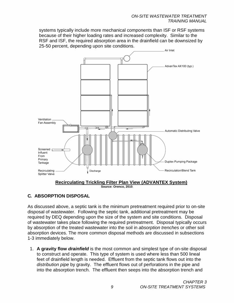
systems typically include more mechanical components than ISF or RSF systems because of their higher loading rates and increased complexity. Similar to the RSF and ISF, the required absorption area in the drainfield can be downsized by 25-50 percent, depending upon site conditions.
Recirculating Trickling Filter Plan View (ADVANTEX System)
Source: Orenco, 2010.
C. ABSORPTION DISPOSAL As discussed above, a septic tank is the minimum pretreatment required prior to on-site disposal of wastewater. Following the septic tank, additional pretreatment may be required by DEQ depending upon the size of the system and site conditions. Disposal of wastewater takes place following the required pretreatment. Disposal typically occurs by absorption of the treated wastewater into the soil in absorption trenches or other soil absorption devices. The more common disposal methods are discussed in subsections 1-3 immediately below. 1. A gravity flow drainfield is the most common and simplest type of on-site disposal
to construct and operate. This type of system is used where less than 500 lineal feet of drainfield length is needed. Effluent from the septic tank flows out into the distribution pipe by gravity. The effluent flows out of perforations in the pipe and into the absorption trench. The effluent then seeps into the absorption trench and
ON-SITE WASTEWATER TREATMENT TRAINING MANUAL
CHAPTER 3 10 ON-SITE TREATMENT SYSTEMS
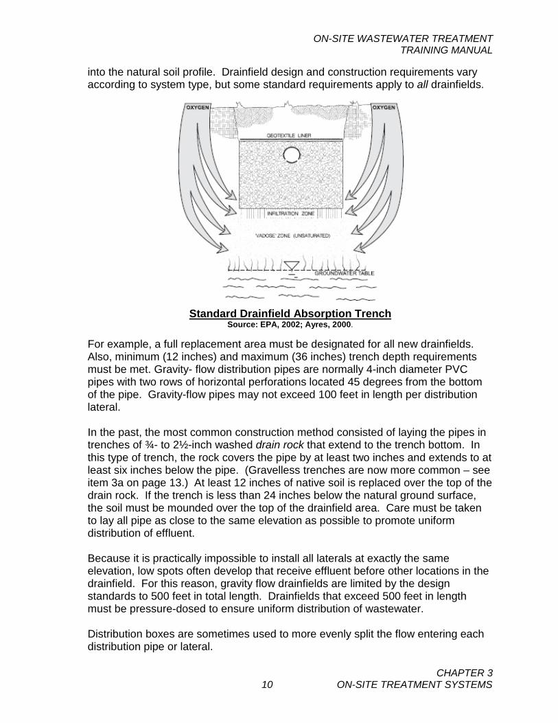
into the natural soil profile. Drainfield design and construction requirements vary according to system type, but some standard requirements apply to all drainfields.
Standard Drainfield Absorption Trench
Source: EPA, 2002; Ayres, 2000. For example, a full replacement area must be designated for all new drainfields. Also, minimum (12 inches) and maximum (36 inches) trench depth requirements must be met. Gravity- flow distribution pipes are normally 4-inch diameter PVC pipes with two rows of horizontal perforations located 45 degrees from the bottom of the pipe. Gravity-flow pipes may not exceed 100 feet in length per distribution lateral. In the past, the most common construction method consisted of laying the pipes in trenches of ¾- to 2½-inch washed drain rock that extend to the trench bottom. In this type of trench, the rock covers the pipe by at least two inches and extends to at least six inches below the pipe. (Gravelless trenches are now more common – see item 3a on page 13.) At least 12 inches of native soil is replaced over the top of the drain rock. If the trench is less than 24 inches below the natural ground surface, the soil must be mounded over the top of the drainfield area. Care must be taken to lay all pipe as close to the same elevation as possible to promote uniform distribution of effluent. Because it is practically impossible to install all laterals at exactly the same elevation, low spots often develop that receive effluent before other locations in the drainfield. For this reason, gravity flow drainfields are limited by the design standards to 500 feet in total length. Drainfields that exceed 500 feet in length must be pressure-dosed to ensure uniform distribution of wastewater. Distribution boxes are sometimes used to more evenly split the flow entering each distribution pipe or lateral.
ON-SITE WASTEWATER TREATMENT TRAINING MANUAL
CHAPTER 3 11 ON-SITE TREATMENT SYSTEMS
Drainfield Distribution Box Source: EPA, 2002; Ayres, 2000.
2. Pressure-dosed drainfields are now commonly used to serve many system sizes.
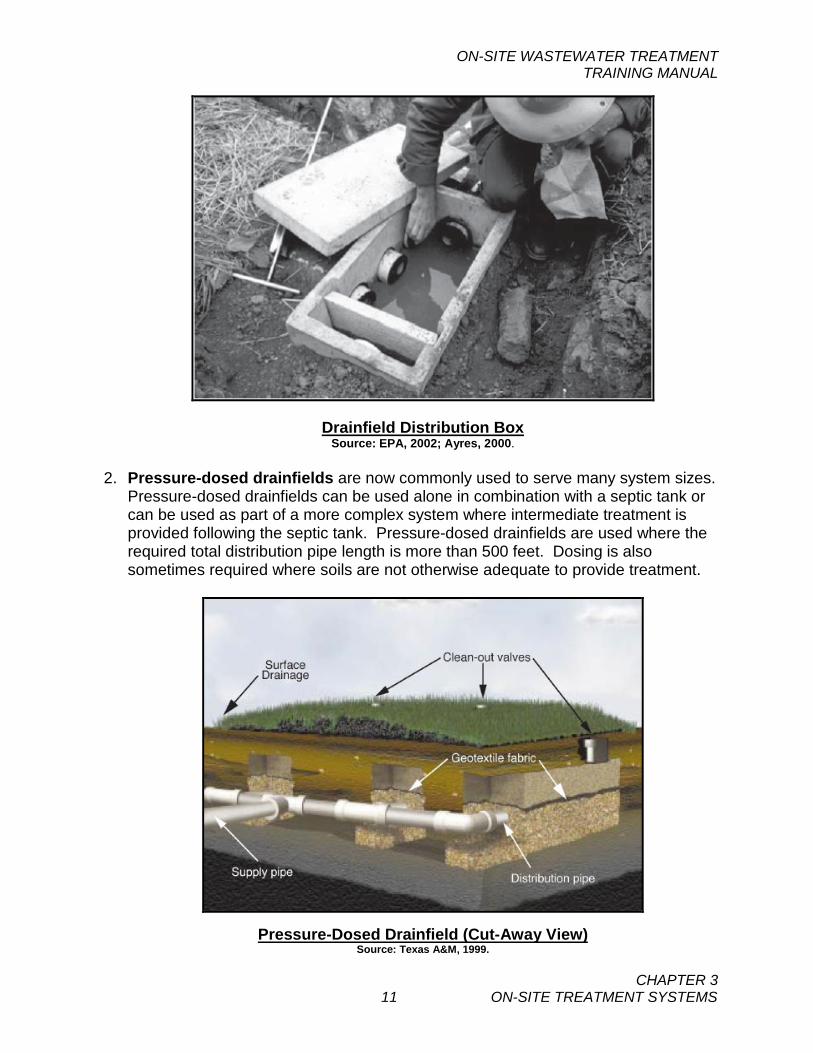
Pressure-dosed drainfields can be used alone in combination with a septic tank or can be used as part of a more complex system where intermediate treatment is provided following the septic tank. Pressure-dosed drainfields are used where the required total distribution pipe length is more than 500 feet. Dosing is also sometimes required where soils are not otherwise adequate to provide treatment.
Pressure-Dosed Drainfield (Cut-Away View) Source: Texas A&M, 1999.
ON-SITE WASTEWATER TREATMENT TRAINING MANUAL
CHAPTER 3 12 ON-SITE TREATMENT SYSTEMS
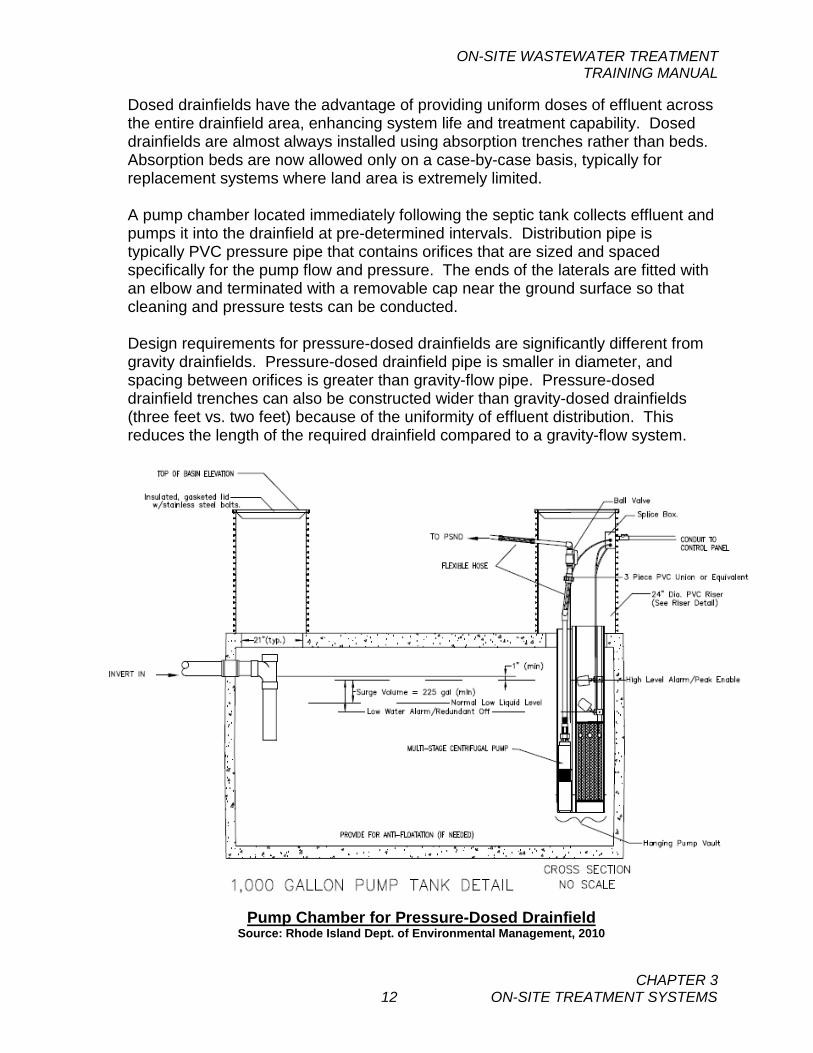
Dosed drainfields have the advantage of providing uniform doses of effluent across the entire drainfield area, enhancing system life and treatment capability. Dosed drainfields are almost always installed using absorption trenches rather than beds. Absorption beds are now allowed only on a case-by-case basis, typically for replacement systems where land area is extremely limited.
A pump chamber located immediately following the septic tank collects effluent and pumps it into the drainfield at pre-determined intervals. Distribution pipe is typically PVC pressure pipe that contains orifices that are sized and spaced specifically for the pump flow and pressure. The ends of the laterals are fitted with an elbow and terminated with a removable cap near the ground surface so that cleaning and pressure tests can be conducted. Design requirements for pressure-dosed drainfields are significantly different from gravity drainfields. Pressure-dosed drainfield pipe is smaller in diameter, and spacing between orifices is greater than gravity-flow pipe. Pressure-dosed drainfield trenches can also be constructed wider than gravity-dosed drainfields (three feet vs. two feet) because of the uniformity of effluent distribution. This reduces the length of the required drainfield compared to a gravity-flow system.
Pump Chamber for Pressure-Dosed Drainfield
Source: Rhode Island Dept. of Environmental Management, 2010
ON-SITE WASTEWATER TREATMENT TRAINING MANUAL
CHAPTER 3 13 ON-SITE TREATMENT SYSTEMS
3. Other methods of absorption disposal provide options for specific site conditions. As with all other system components, be sure to heck with the appropriate regulatory authority before designing or constructing any of these disposal systems:
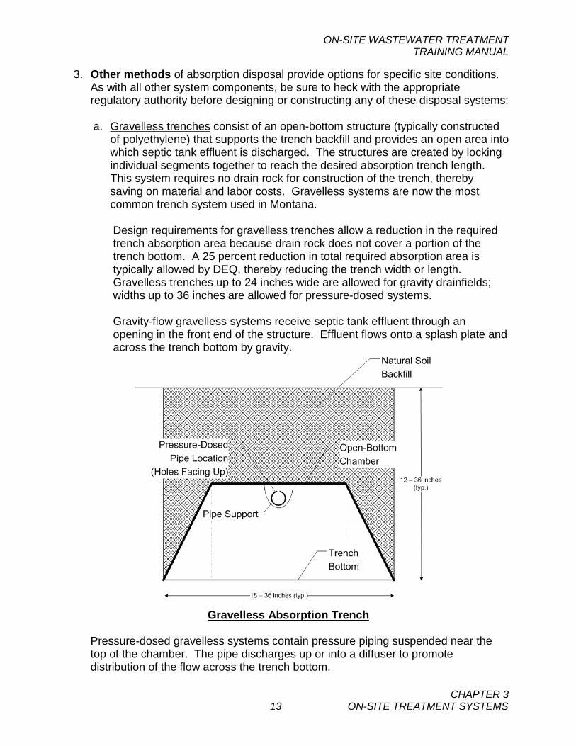
a. Gravelless trenches consist of an open-bottom structure (typically constructed
of polyethylene) that supports the trench backfill and provides an open area into which septic tank effluent is discharged. The structures are created by locking individual segments together to reach the desired absorption trench length. This system requires no drain rock for construction of the trench, thereby saving on material and labor costs. Gravelless systems are now the most common trench system used in Montana.
Design requirements for gravelless trenches allow a reduction in the required trench absorption area because drain rock does not cover a portion of the trench bottom. A 25 percent reduction in total required absorption area is typically allowed by DEQ, thereby reducing the trench width or length. Gravelless trenches up to 24 inches wide are allowed for gravity drainfields; widths up to 36 inches are allowed for pressure-dosed systems. Gravity-flow gravelless systems receive septic tank effluent through an opening in the front end of the structure. Effluent flows onto a splash plate and across the trench bottom by gravity.
Gravelless Absorption Trench
Pressure-dosed gravelless systems contain pressure piping suspended near the top of the chamber. The pipe discharges up or into a diffuser to promote distribution of the flow across the trench bottom.
ON-SITE WASTEWATER TREATMENT TRAINING MANUAL
CHAPTER 3 14 ON-SITE TREATMENT SYSTEMS
b. Sand-lined trenches may be required where soil conditions are either too
porous/rocky or where soils are too heavy. Sand must be installed at least 12 inches deep in the bottom of the absorption trenches. Sand-lining of the sidewalls may also be required. Pressure dosing of effluent may be required, depending upon site conditions.
c. Deep absorption trenches may be approved only where an impermeable or
restrictive soil layer prevents penetration of effluent in the drainfield above this depth. The bottoms of deep trenches may be no deeper than 60 inches below the ground surface. Additional construction requirements beyond that of a standard absorption trench will apply, depending upon the exact site conditions.
d. Evapotranspiration systems may be approved where climate, tight soils and/or
other site conditions are not favorable to more conventional systems. The system relies either partially or completely upon evapotransporation of the wastewater effluent. Large surface areas are typically required and significant water conservation is normally necessary to minimize the amount of wastewater generated. Evapotranspiration systems are expensive to construct and do not work well in wet, cool climates.
e. Elevated sand mounds may be approved where inadequate separation exists
between the ground surface and bedrock or groundwater. Sand mounds are challenging to design and construct and must be approved in advance by the appropriate regulatory agencies.
ON-SITE WASTEWATER TREATMENT TRAINING MANUAL
CHAPTER 3 15 ON-SITE TREATMENT SYSTEMS
SELF-STUDY QUESTIONS - CHAPTER 3 1. A common reason for the failure of a residential septic systems is:
(a) Failure to regularly pour septic tank additives into the tank. (b) Contamination by laundry detergents. (c) Lack of periodic pumping of the septic tank. (d) All of the above
3. The contents of a properly functioning septic tank can best be described by the following:
(a) A septic layer, an aerobic layer and a surface overflow. (b) A septic layer, a scum layer, and a surface overflow. (c) A sludge layer, a scum layer and a clear layer. (d) An anaerobic sludge layer, a facultative liquid layer and an aerobic scum layer.
4. Bacteria that require dissolved oxygen to live and grow are:
(a) Aerobic bacteria (b) Anaerobic bacteria (c) Facultative bacteria (d) All of the above
4. The oxygen in a typical drainfield is:
(a) Formed primarily by anaerobic bacteria. (b) Formed primarily by aerobic bacteria. (c) Obtained primarily by mechanical means. (d) Naturally present in the upper soil profile.
5. You would expect to find anaerobic bacteria:
(a) In the upper levels of a septic tank. (b) Distributed uniformly throughout the drainfield. (c) Distributed uniformly throughout the septic tank. (d) All of the above
6. Anaerobic bacteria can produce:
(a) Methane (b) Ammonia (c) Hydrogen sulfide (d) All of the above
7. Facultative bacteria have the ability to: (a) Exist in both aerobic and anaerobic conditions. (b) Regrow after being dried out. (c) Convert carbon dioxide to oxygen. (d) All of the above.
ON-SITE WASTEWATER TREATMENT TRAINING MANUAL
CHAPTER 3 16 ON-SITE TREATMENT SYSTEMS
8. Treatment of wastewater in a drainfield is accomplished by: (a) Biological activity on the wastewater constituents. (b) Disinfection of the bacteria. (c) Adsorption of the nitrates on soil particles. (d) All of the above.
9. Pressure-dosed subsurface disposal systems offer which of the following advantages over gravity distribution disposal systems?
(a) DEQ credits more absorption area per lineal foot of trench length. (b) They provide slow seepage of effluent out of the disposal trenches. (c) They provide a “resting” period for the disposal system. (d) a and c above.
10. The biological nitrification process in a recirculating sand filter treatment system will
normally take place: (a) In the septic tank. (b) In the recirculation tank. (c) On the surface of the grains of sand in the filter. (d) In or below the biomat layer in the drainfield. (e) c and d above.
ON-SITE WASTEWATER TREATMENT TRAINING MANUAL
CHAPTER 4 1 WASTEWATER COLLECTION
CHAPTER 4 A. COLLECTION SYSTEMS Wastewater collection systems, or sanitary sewers, are used to connect sources of wastewater, homes, commercial establishments and industries, to wastewater treatment plants (WWTP). The components needed to collect, pump and discharge wastewater to the treatment facility is called the collection system. Collection systems, sometimes called conveyance systems, consist of a series of connected underground pipes and any associated pumping stations that carry wastes from the customer to a WWTP. Collection systems are sized based upon the type of waste conveyed and the volume of flow. The most common type of system uses a series of underground pipes to collect raw sewage from customers’ service lines. Concrete manholes are located at changes in pipe grade or direction and are regularly spaced to allow access to the pipe sections for maintenance. Pipes carrying raw sewage must be designed to keep flow moving at two feet per second or more to prevent solid materials from settling and accumulating. Pipes that carry raw sewage are normally at least eight inches in diameter. Pipes in collection systems that carry only septic tank effluent can be sized smaller and large diameter manholes can often be replaced with small diameter cleanouts. In order to take full advantage of gravity flow, septic tank effluent gravity (STEG) systems may be used. Each user has a septic tank and the collection system carries only septic tank effluent by gravity. This allows more flexibility and reduced expenses in the design and construction of the collection system. In any gravity system, collection piping typically is buried deeper as the piping approaches the WWTP. As piping gets deeper, pump stations (also known as lift stations) may be required to elevate the wastewater so that it can flow downward again to the next pump station or treatment plant. Other types of collection systems, such as septic tank effluent pumping (STEP) systems, rely on a series of small pumps attached to the piping system to convey the wastes to the WWTP. These pumps are usually located immediately after the septic tanks on the customers’ properties. STEP systems offer the advantage of following the contours of the land without need for deep sewers or large pump stations.
KEY WORDS AMPERAGE CENTRIFUGAL PUMP CIRCULAR DEQ-2 COMBINED SEWER COLLECTION SYSTEM CURRENT FORCE MAIN INFILTRATION INFLOW PUMP STATION RESISTANCE STEP STEG SUBMERSIBLE TOTAL DYNAMIC HEAD VOLTAGE WATER HAMMER
ON-SITE WASTEWATER TREATMENT TRAINING MANUAL
CHAPTER 4 2 WASTEWATER COLLECTION
Collection pipes can be made of different materials such as clay, concrete or plastic compounds. The materials should resist corrosion, since wastewater can contain or generate dangerous gases or chemicals that can cause the pipes to deteriorate. Pipe systems in poor condition can leak, allowing infiltration by groundwater into the wastewater or allowing wastewater to exfiltrate into the groundwater. Either situation will cause problems at the WWTP or in groundwater, potentially impacting the environment or public health. Other sources of water into collection systems include storm water and illegal inflow sources. Storm water collection systems gather excess rainwater and snowmelt and carry it to surface water outlets or treatment facilities or combine it with sanitary sewers. When storm drains are attached to sanitary sewers, the extra water can wreak havoc in the treatment plants. Combined sewers with storm and domestic wastewater should be separated to prevent problems with collecting and treating domestic wastes. Illegal inflow sources include roof drains from buildings and sump pumps from basements. The amount of wastewater treated in a WWTP can be measured by checking flows at various locations in the collection system, in pump stations and at the wastewater treatment facility. Often, infiltration and inflow (I/I) sources can be identified and removed. The overall volume of I/I in the total wastewater flow to a WWTP can be significant and can increase the cost of treatment. Short-term flow events causing large amounts of I/I can drastically reduce performance of the treatment system by flushing the beneficial microorganisms into the effluent or by overloading the absorption disposal system. Maintenance of a collection system includes many activities. Flushing the lines will help clear blockages and debris. Using an in-pipe camera system will document the interior condition of pipes and connections, aiding in the repair and replacement of bad sections of the system. Operators must apply all appropriate safety measures when working on the system, monitoring customer discharges and maintaining the pumping stations.
B. PUMP STATIONS, PUMPS AND MOTORS Pump stations (also known as lift stations) are often necessary in a wastewater collection system to collect wastewater at low areas and convey the waste ultimately to the treatment system. Pump stations require significant operation and maintenance and should be avoided in the design of a system where possible, especially where raw sewage is conveyed. Raw sewage pump stations will generally consist of a wet well, pumps, controls, valves and discharge piping or force main. For small STEP systems, the pump station is often located at the customer’s septic tank. A force main carries the pumped fluid to another sewer main or to the treatment plant. The pumps used to convey the wastewater are usually centrifugal pumps (including submersible pumps) designed to carry solids without clogging, although pneumatic air lift pumps have also been used successfully.
ON-SITE WASTEWATER TREATMENT TRAINING MANUAL
CHAPTER 4 3 WASTEWATER COLLECTION
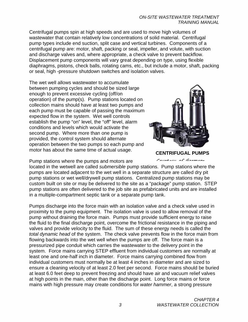
Centrifugal pumps spin at high speeds and are used to move high volumes of wastewater that contain relatively low concentrations of solid material. Centrifugal pump types include end suction, split case and vertical turbines. Components of a centrifugal pump are: motor, shaft, packing or seal, impeller, and volute, with suction and discharge valves and, where appropriate, a check valve to prevent backflow. Displacement pump components will vary great depending on type, using flexible diaphragms, pistons, check balls, rotating cams, etc., but include a motor, shaft, packing or seal, high -pressure shutdown switches and isolation valves. The wet well allows wastewater to accumulate between pumping cycles and should be sized large enough to prevent excessive cycling (off/on operation) of the pump(s). Pump stations located on collection mains should have at least two pumps and each pump must be capable of passing the maximum expected flow in the system. Wet well controls establish the pump “on” level, the “off” level, alarm conditions and levels which would activate the second pump. Where more than one pump is provided, the control system should alternate operation between the two pumps so each pump and motor has about the same time of actual usage. Pump stations where the pumps and motors are located in the wetwell are called submersible pump stations. Pump stations where the pumps are located adjacent to the wet well in a separate structure are called dry pit pump stations or wet well/drywell pump stations. Centralized pump stations may be custom built on site or may be delivered to the site as a “package” pump station. STEP pump stations are often delivered to the job site as prefabricated units and are installed in a multiple-compartment septic tank or a separate pump tank. Pumps discharge into the force main with an isolation valve and a check valve used in proximity to the pump equipment. The isolation valve is used to allow removal of the pump without draining the force main. Pumps must provide sufficient energy to raise the fluid to the final discharge point, overcome the frictional resistance in the piping and valves and provide velocity to the fluid. The sum of these energy needs is called the total dynamic head of the system. The check valve prevents flow in the force main from flowing backwards into the wet well when the pumps are off. The force main is a pressurized pipe conduit which carries the wastewater to the delivery point in the system. Force mains carrying STEP effluent from individual customers are normally at least one and one-half inch in diameter. Force mains carrying combined flow from individual customers must normally be at least 4 inches in diameter and are sized to ensure a cleaning velocity of at least 2.0 feet per second. Force mains should be buried at least 6.0 feet deep to prevent freezing and should have air and vacuum relief valves at high points in the main, other than the discharge point. Long force mains or force mains with high pressure may create conditions for water hammer, a strong pressure
CENTRIFUGAL PUMPS Courtesy of Gorman-
ON-SITE WASTEWATER TREATMENT TRAINING MANUAL
CHAPTER 4 4 WASTEWATER COLLECTION
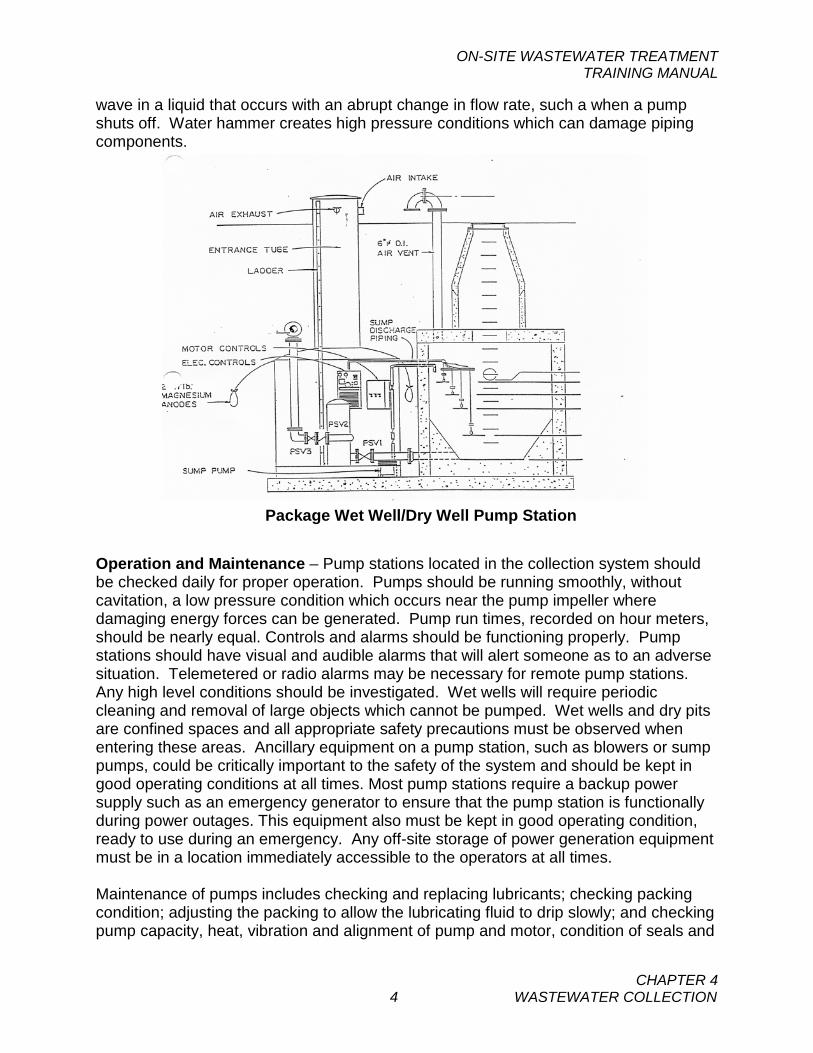
wave in a liquid that occurs with an abrupt change in flow rate, such a when a pump shuts off. Water hammer creates high pressure conditions which can damage piping components.
Operation and Maintenance – Pump stations located in the collection system should be checked daily for proper operation. Pumps should be running smoothly, without cavitation, a low pressure condition which occurs near the pump impeller where damaging energy forces can be generated. Pump run times, recorded on hour meters, should be nearly equal. Controls and alarms should be functioning properly. Pump stations should have visual and audible alarms that will alert someone as to an adverse situation. Telemetered or radio alarms may be necessary for remote pump stations. Any high level conditions should be investigated. Wet wells will require periodic cleaning and removal of large objects which cannot be pumped. Wet wells and dry pits are confined spaces and all appropriate safety precautions must be observed when entering these areas. Ancillary equipment on a pump station, such as blowers or sump pumps, could be critically important to the safety of the system and should be kept in good operating conditions at all times. Most pump stations require a backup power supply such as an emergency generator to ensure that the pump station is functionally during power outages. This equipment also must be kept in good operating condition, ready to use during an emergency. Any off-site storage of power generation equipment must be in a location immediately accessible to the operators at all times. Maintenance of pumps includes checking and replacing lubricants; checking packing condition; adjusting the packing to allow the lubricating fluid to drip slowly; and checking pump capacity, heat, vibration and alignment of pump and motor, condition of seals and
Package Wet Well/Dry Well Pump Station
ON-SITE WASTEWATER TREATMENT TRAINING MANUAL
CHAPTER 4 5 WASTEWATER COLLECTION
worn and broken parts. Individual STEP system pumps should be checked as recommended by the manufacturer or system owner. Operation and maintenance responsibilities for STEP systems are often addressed by homeowners associations or through legal agreements with WWTP system owners. C. MOTORS & ELECTRICITY Electricity is used to drive motors that drive other types of mechanical equipment in wastewater systems. Power supplies for the treatment system must be reliable and, in critical areas of the system, should have a backup electrical generator(s). Electric motors are designed to rotate when electrical current is applied across the poles of the motor. Some motors are two-phase, while three-phase motors are commonly used in wastewater systems. Motors are rated in horsepower, which is a measurement of the work output available to move water, or do other types of work. Centrifugal pumps convert electrical energy to mechanical energy that is used to move liquids and solids in wastewater treatment facilities. Electricity is a source of power derived from the flow of electrons from one place to another. When an electrical difference, or electromotive force, exists between two poles or ends of an electrical system, electrons will flow from one pole to the other. This is much like the flow of water from a high point to a low point. The 'pressure' of the electrical flow is called the voltage (V). The actual flow of electrons from one pole to another is called the amperage (A). This is similar to the flow of water in a pipe. Much like water flowing in a water pipe an electrical circuit has resistance (R), which is similar to headloss in water lines. The relationship between these components is, V = A x R. Electrical flow, or current, comes in two forms, depending on how it was generated or transmitted to the point-of-use: direct current (DC) and alternating current (AC). In DC systems, the flow of electrons is always in a single direction, like that in a car battery from the positive pole to the negative pole. In AC systems, the flow of electrons alternates direction and is typically 60 complete cycles of alternation per second. The term commonly used for cycles per second is Hertz (Hz). AC current is used to run lighting systems, motors and pumps and is more commonly used in our everyday life. Electrical circuits may be open or closed. An open circuit is like having a light switch in the off position, since electrons can't flow through an open switch. When the switch is closed, and the switch points make contact, electricity can now flow to cause a light bulb to glow or run an appliance or motor. Exposed wires and live, or closed, circuits can create dangerous conditions when operators are working on equipment. Control devices such as circuit breakers must be locked out, or locked open, so that maintenance activities can be accomplished safely.
ON-SITE WASTEWATER TREATMENT TRAINING MANUAL
CHAPTER 4 6 WASTEWATER COLLECTION
A tag should be placed on a locked out control device (tagout/lockout) to indicate that the breaker is off for a specific purpose and should not be changed. D. DESIGN AND CONSTRUCTION REQUIREMENTS As discussed in Chapter 3, Circular DEQ-4 is the primary design standard for on-site wastewater systems. Where referenced in DEQ-4, Circular DEQ-2 also applies to the design of certain system components such as collection mains, manholes and pumping stations. DEQ approval must be obtained prior to construction. Following construction, the owner’s engineer must certify to DEQ that the project was built in accordance with the approved documents (or specify what changes were made) and provide as-built drawings. Certification of the improvements must be provided to DEQ prior to use.
ON-SITE WASTEWATER TREATMENT TRAINING MANUAL
CHAPTER 4 7 WASTEWATER COLLECTION
SELF STUDY QUESTIONS – CHAPTER 4 1. Infiltration and inflow in a collection system causes which of the following problems:
(a) Higher BOD concentrations (b) Excessive pumping costs (c) Reduce levels of coliforms (d) All of the above
2. A check valve is used on a pump station for the following reason:
(a) Allow for pump removal (b) Allow for pump inspection (c) Prevent sewage from running backwards after pumping stops (d) Evaluate high pressure conditions
3. What conditions on a force main might cause or indicate water hammer:
(a) A long force main pumping the wastewater hundreds of feet (b) Loud noises when the pump shuts down (c) Pressure fluctuations on the discharge side of the pump (d) All of the above
4. What is not a characteristic of a positive displacement pump?
(a) Good pump for moving thick liquids (b) Moves a fixed volume of fluid per stroke (c) Moves a variable volume of fluid per stroke (d) Requires a piston, diaphragm or lobe
5. Which of the following is true of a 12-volt battery?
(a) The current alternates direction at 60 cycles per sec (b) The voltage is less than resistance if fully charged (c) Delivers direct current (d) All of the above is true
ON-SITE WASTEWATER TREATMENT TRAINING MANUAL
CHAPTER 5
1 LAWS, REGULATIONS& PERMITS
CHAPTER 5 A. WATER QUALITY REQUIREMENTS It is important for the operator to be familiar with the laws, regulations and permits that concern the operation of an on-site wastewater system. The Federal law governing wastewater discharges is the Clean Water Act of 1972 (CWA) and the amendments that have followed. The CWA, as passed by Congress, is the basis for most state laws and regulations. The EPA has established National Secondary Standards which set the minimum acceptable level of wastewater treatment for surface water discharges. No discharges can exceed the limits set out in those standards. The EPA requires permits, testing and reporting for all surface water discharges of wastewater. The Montana Water Quality Act (WQA) is the State version of the CWA. Montana has primacy for the enforcement of many federal laws, which means that the State of Montana is the responsible enforcement agency. If primacy for a given program by a state is not accepted, then enforcement would be by the Environmental Protection Agency (EPA). Groundwater discharges are required to meet state standards established under the Montana Water Quality Act. See Circular DEQ-7 for a comprehensive listing of numeric surface water and groundwater standards.
The Montana WQA establishes the public policy of this state to:
• Conserve water by protecting, maintaining, and improving the quality and potability of water for public water supplies, wildlife, fish and aquatic life, agriculture, industry, recreation, and other beneficial uses;
• Provide a comprehensive program for the prevention, abatement, and control of
water pollution. The Montana WQA gives authority to the State Board of Environmental Review and to the Department of Environmental Quality (DEQ) to adopt rules and regulations. The Act requires a classification of state waters based on beneficial uses and sets standards for purity to maintain or support beneficial uses. These classifications must be reviewed every three years. The WQA requires nondegradation of state waters so that the existing quality of waters will not be lowered. Any new or increased source of possible pollution must provide a
KEY WORDS BIOSOLIDS CLEAN WATER ACT CIRCULAR DEQ-7 CONTINUING EDUCATION DMR MIXING ZONE GROUNDWATER POLLUTION
CONTROL SYSTEM NONDEGRADATION PART 503 SLUDGE REGULATIONS PRETREATMENT OPERATOR IN TRAINING SANITATION IN SUBDIVISIONS ACT SECONDARY STANDARDS WATER QUALITY ACT
ON-SITE WASTEWATER TREATMENT TRAINING MANUAL
CHAPTER 5
2 LAWS, REGULATIONS& PERMITS
degree of treatment to maintain the quality of the receiving stream. Any new or increased discharge must not appreciably change the characteristics of the receiving water. The Administrative Rules of Montana (ARM) 17.30.701-718 contain Montana’s nondegradation requirements. Mixing zones are normally authorized for groundwater discharges. Mixing zones are areas located downgradient of the drainfield within which discharge from the drainfield is allowed to mix with the groundwater. Within the mixing zone, some nondegradation requirements do not apply. Outside the mixing zone, water quality must meet the minimum nondegradation requirements or water quality standards. DEQ rules ARM 17.30.501-508 contain the specific mixing zone requirements. As discussed in Chapter 3, nitrogen levels in the treatment system discharge are often a concern in meeting nondegradation requirements. DEQ may approve certain system types for increased nitrogen removal. These system classifications are:
• Level 1b – Achieves a nitrogen discharge of approximately 40 mg/L • Level 1a – Achieves a nitrogen discharge of approximately 30 mg/L • Level 2 – Achieves a nitrogen discharge of approximately 24 mg/L
DEQ should be contacted with any questions regarding system installation or modifications with respect to these level classifications. The WQA also provides authority to DEQ to implement a Montana Ground Water Pollution Control System (MGWPCS). A MGWPCS permit must be issue for each on-site system that discharges 5,000 gallons per day (gpd) or more. The permit will give effluent limitations, testing and reporting requirements. The permit is valid for five years at which time an application for renewal must be made 180 days before expiration. DEQ rules ARM 17.30.1001-1045 contain the specific MGWPCS requirements. Most discharges from on-site systems will be monitored prior to discharge to the drainfield. These samples will be grab samples or composite samples (samples collected over a 24-hour period), depending upon the type of system and the parameter sampled. Monitoring will also likely be required at a monitoring well constructed down-gradient from the drainfield near the end of the mixing zone. These samples will be grab or instantaneous samples. Monitoring from both locations is typically required. The permit will list the self-monitoring requirements, the frequency of sampling and type of analysis to be performed. Parameters monitored at the discharge to the drainfield typically include flow rate, BOD, Total Kjeldahl nitrogen (TKN – the sum of organic nitrogen, ammonia and the ammonium ion), total nitrogen, nitrate, nitrite, ammonia, phosphorous and total suspended solids (TSS). Parameters required at the monitoring well will normally include: static groundwater level below the ground surface, specific conductance, chloride, E. coli, ammonia, total nitrogen, nitrate, nitrite and phosphorous. If the system discharges to groundwater near high-quality water or into a stream with relatively low flow compared to the system flow, other water quality limits may be
ON-SITE WASTEWATER TREATMENT TRAINING MANUAL
CHAPTER 5
3 LAWS, REGULATIONS& PERMITS
applied as necessary to maintain instream water quality. Some wastewater constituents can be quite toxic to fish or other aquatic life. Among these are ammonia, chlorine, and heavy metals. Fecal coliform is more strictly regulated in many discharges during the months when swimming or other activities might involve public contact with the water. The impact of each discharge upon the receiving water is evaluated by the DEQ in setting permit limits. In order for the DEQ to carry out its mandate for protection of State waters, it is necessary to know the location, quantity and quality of each discharging system. This is accomplished by the Discharge Monitoring Report (DMR) Form (EPA No.3320-1) which must be submitted no later than the 28th day of the month following the completed report period. See appendix C for an example of this form. Copies of these DMR reports must be submitted to the
Montana Department of Environmental Quality –Water Protection Bureau PO Box 200901 Helena, MT 59620-0901 Phone (406) 444-3080
Even if there is no discharge during the reporting period, a report must be submitted stating "No Discharge." All records of operation, sampling, testing and reporting must be kept on file for three years and available for inspection. Sludge records must be kept for five years. The Montana Department Environmental Quality has the legal right of access to any facility to inspect the operations and records. The department has authority to initiate legal proceedings against any party in violation of the laws. The Montana WQA provides for administrative penalties of up to $10,000 per day or civil penalties of up to $25,000 per day for violation of the rules. Each day of violation can be a separate violation. Willful or negligent violations can be a criminal offense with fines and imprisonment of up to one year. The Montana Sanitation in Subdivisions Act (SSA) also applies to on-site systems serving subdivisions. The following rules adopted under authority of the SSA are of particular interest to the design, operation and maintenance of on-site systems in addition to those cited above:
• ARM 17.36.301-345 Subdivision Requirements.
• ARM 17.36.901-924 On-site Subsurface Wastewater Treatment Systems. These rules contain specific requirements for siting of subdivisions and the design of on-site wastewater systems in subdivisions.
ON-SITE WASTEWATER TREATMENT TRAINING MANUAL
CHAPTER 5
4 LAWS, REGULATIONS& PERMITS
Personnel at the DEQ want to work with communities and operators for improvement in water quality. Should any questions arise concerning operations, requirements, permits, or any other matter, the operator should feel free to contact DEQ. If any change from normal operation is contemplated, the operator should contact DEQ staff for advice. Physical changes to the system will likely require prior review by DEQ. B. BIOSOLIDS (SLUDGE) DISPOSAL Sewage sludge or “Biosolids” are defined as the solid, semi-solid, or liquid residue generated during the treatment of domestic sewage in a wastewater treatment plant. Biosolids includes scum or solids removed during the primary, secondary or advanced treatment processes, domestic septage, and solids removed from wastewater treatment lagoons. Biosolids does not include grit, screenings or trash removed from wastewater during preliminary treatment processes. In 1993, the EPA implemented rules governing the disposal and recycling of biosolids. These rules are known as the “Standards for the Use or Disposal of Sewage Sludge” and are found under Chapter 40 of the Code of Federal Regulations, (40 CFR) Part 503. Most biosolids disposal and reuse practices, including land application, surface disposal and incineration are governed by these rules. The State of Montana does not administer sludge disposal standards for the EPA. Consequently, the local EPA office in Helena can be contacted at 406-457-5023 for more information regarding the proper disposal of biosolids. Land application is the most common form of biosolids disposal, and one of the most highly regulated by Part 503. In order to land apply biosolids, the material must not exceed established limitations for 10 heavy metals, must not exceed established limitations for pathogens, must be adequately stabilized or isolated to reduce attraction to insects or other vectors, and the application rate must match the nitrogen uptake rate of whatever vegetation exists at the application site. Records on how the sludge disposal practices satisfy the regulatory criteria must be maintained for at least 5 years. Surface disposal practices are also governed by Part 503. Surface disposal differs from land application in that surface disposal is done without regard to nitrogen loading. In order to surface dispose of biosolids, the material must not exceed established limitations for 3 heavy metals and pathogens and must be adequately stabilized or isolated to reduce attraction to vectors. Surface disposal ordinarily involves high-rate land application or burying sludge. Landfilling of biosolids is a disposal alternative that is not covered by the EPA Part 503 regulations is landfilling. Landfilling operations are governed by the EPA Part 257 regulations that require biosolids to be “non-hazardous” and “non-liquid”. Biosolids can be found “non-hazardous” by performing a test to show that the level of 8 heavy metals in the material is below specific limits. The material must also be tested for water content using the “Paint Filter Test”. If this test demonstrates that no water leaks out of the biosolids, then it can be declared “non-liquid”. If the biosolids material satisfies both of these requirements, it can be landfilled.
ON-SITE WASTEWATER TREATMENT TRAINING MANUAL
CHAPTER 5
5 LAWS, REGULATIONS& PERMITS
Operators of residential on-site wastewater systems that hire septic tank pumpers to pump and dispose of solids are not required to obtain separate approvals or permits for sludge disposal. However, operators should make sure to check that the pumper has a valid current license from the DEQ. Operators of on-site systems that accept commercial or industrial waste should contact the DEQ Waste Management Bureau at (406) 444-1434 to determine if other requirements apply C. OPERATOR CERTIFICATION Montana law MCA 37-42-101 states that, “It is declared that the health and welfare of Montana citizens are jeopardized by persons not properly qualified to operate the water supply systems and that Montana’s state waters are endangered by persons not properly qualified to operate the wastewater treatment plants. It is declared that the public policy of this state is to protect the public health and safety by certifying persons working in these occupations.” All wastewater treatment plants, including on-site systems, that meet the classifications outlined in ARM 17.40.202(1)(c) must be operated by at least one properly certified operator. The operator is certified by passing an examination and meeting certain experience and education requirements for the class of facility operated. The on-site systems and their respective classes of operators are described as follows:
Class 2E-- Onsite package biological wastewater treatment systems including conventional activated sludge, SBR, fixed film and extended aeration systems with discharge to groundwater. Must be a public sewage system and be regulated with a MGWPCS discharge permit Class 3E--Onsite treatment systems including recirculating media trickling filters, intermittent sand filters, recirculating sand filters, aerobic wastewater treatment units and chemical nutrient reduction systems as described in Circular DEQ-4. Must be a public sewage system and be regulated with a MGWPCS discharge permit; Class 4E--Onsite septic tank primary treatment systems with complex or pumped sub-surface soil absorption systems including pressure-dosed drainfields, siphon-dosed drainfields, elevated sand mound systems, deep absorption trenches, subsurface drip systems and other systems described in DEQ-4 exclusive of those considered under Class 2 and Class 3 onsite systems. This class also includes onsite septic tank primary treatment systems with simple sub-surface disposal by a gravity drainfield. Must be a public sewage system and be regulated with a MGWPCS discharge permit.
These classes refer to the term “public sewage systems” which is defined as a system of collection, transportation, treatment, or disposal of sewage that serves 15 or
ON-SITE WASTEWATER TREATMENT TRAINING MANUAL
CHAPTER 5
6 LAWS, REGULATIONS& PERMITS
more families or 25 or more persons daily for any 60 or more days in a calendar year. Unless granted a special exception, all operators are required to have a high school education (or G.E.D.). A Class 2 applicant must have one and one-half years of experience before becoming fully certified. A Class 3 applicant must have one year of experience before becoming a fully certified operator. A Class 4 applicant must have 6 months of experience to become fully certified. THE KEY STEPS IN BECOMING A CERTIFIED OPERATOR ARE AS FOLLOWS:
• Request Application (406-444-4584 or 406-444-3434) • Read Information Received Thoroughly • Fully Complete Application • Determine What Class and Type of System • Fill in All Applicable Experience (water and wastewater only) • Fill in All Applicable Education • Sign the Application and Mail Back with Fees
a. The office must have new applications for 30 days before an exam can be taken
• Send Back Examination Notice by Deadline (15 days before exam) • Receive Study Materials from Certification Office • Take Examination and Wait for Results
Applicants who pass the examination but do not have the working experience can be issued a certificate as Operator-In-Training until the experience requirement is met. Certification means that an applicant has the basic knowledge and skills necessary to operate any facility in that classification. Certification is not issued as a permit to operate only the plant in which the holder is currently employed. The applicant for a certificate should be knowledgeable in all types of systems within and below his certification grade. All fully certified operators must earn continuing education credits (CEC's). These are earned by attendance at approved programs and classes. One credit is given for ten contact hours in the program or class during a designated two-year period. All Class 2, 3 and 4 operators must earn one credit during the period. This is the equivalent of 10 hours of classroom or approved program participation. It is the operator's responsibility to see that all continuing education credits are submitted. Without these credits, renewal of certification will be denied. Certified operators are required by law to be "readily available at all times." Problems often arise when least expected which may require the immediate action of the certified operator. The certified operator also acts as the contact person for DEQ staff who may find it necessary to call about some question or who may be inspecting the wastewater system periodically. To assure that at least one certified operator is always readily available, communities should have two certified operators or a back-up operator from a nearby community with a similar or greater level of certification.
ON-SITE WASTEWATER TREATMENT TRAINING MANUAL
CHAPTER 5
7 LAWS, REGULATIONS& PERMITS
Because certified operators are initially and continually trained, they offer the best protection for good operation and maintenance of treatment systems. In addition, by seeing that the treatment system is maintained to do its job in the best possible way, they also protect the large monetary investment made by the community, often with the support of the federal government. For further information on certification, you may call or write:
Water/Wastewater Operator Certification PO Box 200901 Helena, MT 59620-0901 Phone: 406-444-2691
D. DESIGN AND CONSTRUCTION REQUIREMENTS As discussed in previous chapters, Circular DEQ-4 is the primary design standard for on-site wastewater systems. Where referenced in DEQ-4, Circular DEQ-2 also applies to the design of certain system components such as collection mains, manholes and pumping stations. DEQ approval must be obtained prior to construction. Following construction, the owner’s engineer must certify to DEQ that the project was built in accordance with the approved documents (or specify what changes were made) and provide as-built drawings. Certification of the improvements must be provided to DEQ prior to use.
ON-SITE WASTEWATER TREATMENT TRAINING MANUAL
CHAPTER 5
8 LAWS, REGULATIONS& PERMITS
E. SELF-STUDY QUESTIONS - CHAPTER 5 1. Primacy means that:
(a) The federal government agents have the right to inspect treatment facilities (b) The state government has responsibility for enforcement of the federal laws (c) The federal laws do not apply in Montana (d) State laws have primacy over federal laws
2. The National Secondary Standards are: (a) A set of guidelines for operation and maintenance
(b) Standards for water quality by secondary treatment facilities (c) The design criteria for on-site systems. (d) A national environmental organization
3. The Montana Water Quality Act:
(a) Requires all wastewater to be treated to drinking water quality. (b) Requires all state water to be suitable for trout habitat (c) Requires beneficial use classification of all state surface waters (d) Requires that water rights be granted.
4. Nondegradation of state waters means that:
(a) Chlorine cannot be used to disinfect effluent (b) Each effluent is to be treated to drinking water quality (c) Any new or increased discharge must not appreciably lower the quality of the
receiving stream (d) Watersheds of the state have been graded into classifications
5. A groundwater discharge permit will be required for:
(a) All discharges to groundwater (b) Discharges of 5,000 gallons per day or more (c) Discharges within 500 feet of surface water (d) All of the above
6. A groundwater discharge permit will most likely require:
(a) Monthly grab samples of discharge to the drainfield (b) Quarterly grab samples of discharge to the drainfield (c) Samples of discharge to the drainfield (d) Quarterly composite samples from a monitoring well
ON-SITE WASTEWATER TREATMENT TRAINING MANUAL
CHAPTER 5
9 LAWS, REGULATIONS& PERMITS
7. After a discharge permit has been issued, the operator:
(a) Can discharge anything provided that it does not violate the permit (b) Can exceed the permit limits as long as the DEQ is notified that it is difficult to
meet the permit limits (c) Does not need to make a DMR report if there is no appreciable discharge for
the month (d) Must make a DMR report every monitoring period whether there is a discharge
or not 8. To be a fully certified operator, an applicant must:
(a) Pass an examination (b) Graduate from high school and pass an examination (c) Have one year of experience (d) Graduate from high school, pass an examination and have the specified
experience 9. During each two-year period, a certified operator must earn continuing education
credits. Class 3 on-site system operators need:
(a) 1 credit within a designated two-year period (b) 2 credits within a designated two-year period (c) 1/2 credit every two years (d) 1/2 credit every year
ON-SITE WASTEWATER TREATMENT TRAINING MANUAL
CHAPTER 6 1 SAMPLING
CHAPTER 6 SAMPLING Taking samples is one of the operator's most important duties. A correctly taken sample is necessary so that the analysis will accurately represent how the operation is performing. The analysis of a sample, no matter how carefully and precisely performed, will reflect both good and bad sampling procedures. Results from sampling and testing are reported to the regulatory agency. If improperly taken samples are represented as being a true picture of the plant operation, the operator may be held responsible for misrepresentation of facts and subject to criminal penalties. It is very important that the operator take the time and effort to be certain that the samples taken are truly representing the conditions present in the treatment system. Here are some rules that should be followed: 1. Always take treatment process samples from a well-mixed flow. Samples taken
from a quiet zone may not be representative. 2. Always use a proper sample container. Always use containers from a laboratory
accepted by DEQ. 3. Some samples must be tested immediately after being taken. Residual chlorine,
temperature, pH and dissolved oxygen should be tested immediately. If samples are to be sent to a laboratory, contact the lab for sampling containers and instructions.
4. Most samples will likely be sent to another location for laboratory testing. These
should be immediately placed in a refrigerator and packed in ice for shipping. They must be kept cold. The laboratory can provide specific instructions on preservation and shipping of samples.
5. A sample tag should be placed on the sample container which lists the type of
sample, where it was taken, the date and time of sampling and name of the person taking the sample. This information should also be recorded in a sampling log.
6. Samples for MGWPCS groundwater discharges are normally required prior to
discharge to the drainfield and from a groundwater monitoring well. 7. Where required by DEQ or otherwise needed, samples for dissolved oxygen must
be taken with a sampler that does not allow air entrainment.
KEY WORDS WELL-MIXED SAMPLING LOG AIR ENTRAINMENT GRAB SAMPLE COMPOSITE SAMPLE DISSOLVED OXYGEN
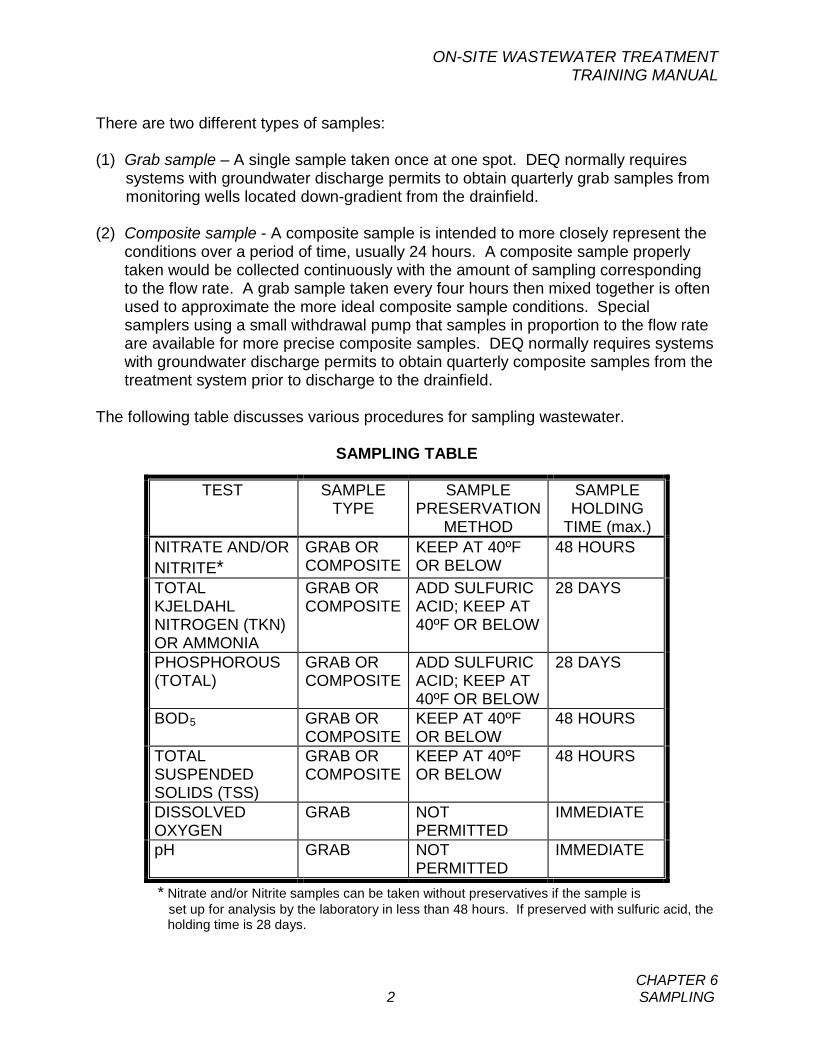
ON-SITE WASTEWATER TREATMENT TRAINING MANUAL
CHAPTER 6 2 SAMPLING
There are two different types of samples: (1) Grab sample – A single sample taken once at one spot. DEQ normally requires
systems with groundwater discharge permits to obtain quarterly grab samples from monitoring wells located down-gradient from the drainfield.
(2) Composite sample - A composite sample is intended to more closely represent the
conditions over a period of time, usually 24 hours. A composite sample properly taken would be collected continuously with the amount of sampling corresponding to the flow rate. A grab sample taken every four hours then mixed together is often used to approximate the more ideal composite sample conditions. Special samplers using a small withdrawal pump that samples in proportion to the flow rate are available for more precise composite samples. DEQ normally requires systems with groundwater discharge permits to obtain quarterly composite samples from the treatment system prior to discharge to the drainfield.
The following table discusses various procedures for sampling wastewater.
SAMPLING TABLE
TEST SAMPLE TYPE
SAMPLE PRESERVATION
METHOD
SAMPLE HOLDING
TIME (max.) NITRATE AND/OR NITRITE*
GRAB OR COMPOSITE
KEEP AT 40ºF OR BELOW
48 HOURS
TOTAL KJELDAHL NITROGEN (TKN) OR AMMONIA
GRAB OR COMPOSITE
ADD SULFURIC ACID; KEEP AT 40ºF OR BELOW
28 DAYS
PHOSPHOROUS (TOTAL)
GRAB OR COMPOSITE
ADD SULFURIC ACID; KEEP AT 40ºF OR BELOW
28 DAYS
BOD5 GRAB OR COMPOSITE
KEEP AT 40ºF OR BELOW
48 HOURS
TOTAL SUSPENDED SOLIDS (TSS)
GRAB OR COMPOSITE
KEEP AT 40ºF OR BELOW
48 HOURS
DISSOLVED OXYGEN
GRAB NOT PERMITTED
IMMEDIATE
pH GRAB NOT PERMITTED
IMMEDIATE
* Nitrate and/or Nitrite samples can be taken without preservatives if the sample is set up for analysis by the laboratory in less than 48 hours. If preserved with sulfuric acid, the holding time is 28 days.
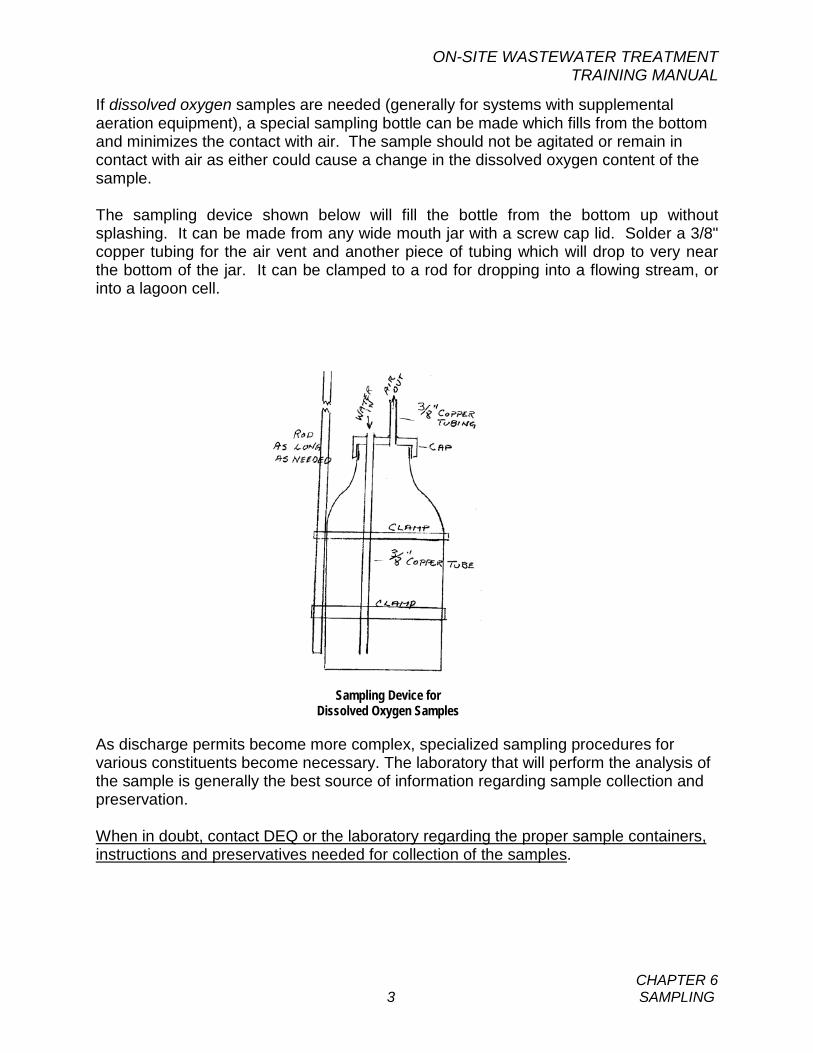
ON-SITE WASTEWATER TREATMENT TRAINING MANUAL
CHAPTER 6 3 SAMPLING
If dissolved oxygen samples are needed (generally for systems with supplemental aeration equipment), a special sampling bottle can be made which fills from the bottom and minimizes the contact with air. The sample should not be agitated or remain in contact with air as either could cause a change in the dissolved oxygen content of the sample. The sampling device shown below will fill the bottle from the bottom up without splashing. It can be made from any wide mouth jar with a screw cap lid. Solder a 3/8" copper tubing for the air vent and another piece of tubing which will drop to very near the bottom of the jar. It can be clamped to a rod for dropping into a flowing stream, or into a lagoon cell.
As discharge permits become more complex, specialized sampling procedures for various constituents become necessary. The laboratory that will perform the analysis of the sample is generally the best source of information regarding sample collection and preservation. When in doubt, contact DEQ or the laboratory regarding the proper sample containers, instructions and preservatives needed for collection of the samples.
Sampling Device for Dissolved Oxygen Samples
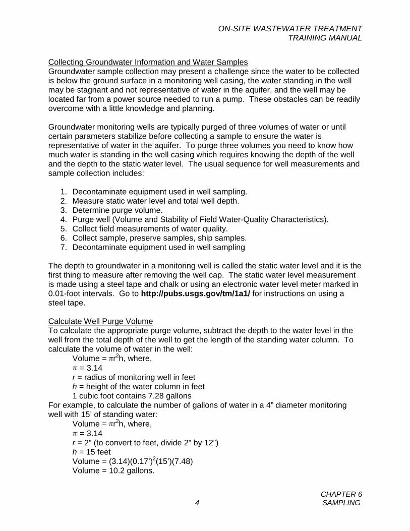
ON-SITE WASTEWATER TREATMENT TRAINING MANUAL
CHAPTER 6 4 SAMPLING
Collecting Groundwater Information and Water Samples Groundwater sample collection may present a challenge since the water to be collected is below the ground surface in a monitoring well casing, the water standing in the well may be stagnant and not representative of water in the aquifer, and the well may be located far from a power source needed to run a pump. These obstacles can be readily overcome with a little knowledge and planning. Groundwater monitoring wells are typically purged of three volumes of water or until certain parameters stabilize before collecting a sample to ensure the water is representative of water in the aquifer. To purge three volumes you need to know how much water is standing in the well casing which requires knowing the depth of the well and the depth to the static water level. The usual sequence for well measurements and sample collection includes:
1. Decontaminate equipment used in well sampling. 2. Measure static water level and total well depth. 3. Determine purge volume. 4. Purge well (Volume and Stability of Field Water-Quality Characteristics). 5. Collect field measurements of water quality. 6. Collect sample, preserve samples, ship samples. 7. Decontaminate equipment used in well sampling
The depth to groundwater in a monitoring well is called the static water level and it is the first thing to measure after removing the well cap. The static water level measurement is made using a steel tape and chalk or using an electronic water level meter marked in 0.01-foot intervals. Go to http://pubs.usgs.gov/tm/1a1/ for instructions on using a steel tape. Calculate Well Purge Volume To calculate the appropriate purge volume, subtract the depth to the water level in the well from the total depth of the well to get the length of the standing water column. To calculate the volume of water in the well:
Volume = r2h, where, = 3.14
r = radius of monitoring well in feet h = height of the water column in feet 1 cubic foot contains 7.28 gallons
For example, to calculate the number of gallons of water in a 4” diameter monitoring well with 15’ of standing water:
Volume = r2h, where, = 3.14
r = 2” (to convert to feet, divide 2” by 12”) h = 15 feet Volume = (3.14)(0.17’)2(15’)(7.48) Volume = 10.2 gallons.
ON-SITE WASTEWATER TREATMENT TRAINING MANUAL
CHAPTER 6 5 SAMPLING
Well Purge Procedure. A monitoring well is purged of three well bore volumes or until the field parameters (pH, temperature, and specific conductance) stabilize. Where power is not available, a bailer may be used for purging and sample collection. Monitoring Well Sampling Procedure. Groundwater samples can be collected directly from decontaminated pump discharge hose or bailer into the sample container. Care must be exercised to avoid contaminating the sample or any of the collection equipment. As with surface water, groundwater samples are stored in an ice chest, kept at 4 degrees Celsius (C), and transported or shipped under chain of custody protocol to the analytical laboratory.
ON-SITE WASTEWATER TREATMENT TRAINING MANUAL
CHAPTER 6 6 SAMPLING
SELF-STUDY QUESTIONS - CHAPTER 6 1. Samples required by DEQ for permit compliance:
(a) May be analyzed by the operator on-site if proper preservatives are not available (b) Must be refrigerated or iced prior to sampling (c) May be analyzed by the operator on-site if the laboratory is closing for the
weekend (d) Must be analyzed by a laboratory accepted by DEQ
2. Nitrate/Nitrite samples:
(a) May be taken without preservative if shipped to the lab within 28 days (b) May be taken without preservative if shipped to the lab within 48 hours (c) Are only taken as grab samples (d) Are only taken as composite samples
3. The maximum time between sampling and starting a BOD test is:
(a) It must be run immediately (b) 8 hours (c) 24 hours (d) 48 hours
ON-SITE WASTEWATER TREATMENT TRAINING MANUAL
CHAPTER 7 1 SAFETY
CHAPTER 7 A. GENERAL All employees working around a wastewater treatment system should be aware of the hazards that exist there. These hazards may not be readily apparent, but without constant vigilance someone can be hurt or even lose their life. The hazards listed in this Chapter may not include everything. Make a close inspection of your facility and list all of the possibilities for an accident that you can find. Practice good personal hygiene whenever working around wastewater. Use the right tool for the right job. Back injuries are one of the most frequent injuries suffered by wastewater plant personnel. Lift things properly and get help when needed. No smoking on the job except where permitted. Hold regular safety meetings with other plant staff and discuss hazards associated with the job and how best to avoid them. Keep notes of the meeting and distribute them to the staff. Public employees such as state, county, city, town and district staff are covered for safety through the Department of Labor and Industry which has adopted OSHA safety rules. OSHA covers the private sector, called general industry. All systems, even though they may be rated as public under the MT DEQ’s criteria of 15 homes or 25 people but are privately owned are covered by OSHA. The OSHA number at the Billings office is (406) 247-7494. B. CHEMICALS If gas chlorine is used, special safety practices must be observed. Chlorine is very poisonous. All chlorine cylinders (especially the ones in use!) must be provided with a safety chain to prevent them from falling. A self-contained breathing apparatus (SCBA) must be available and ready for use. Frequently check the air supply in the SCBA cylinder and replace when it gets low. A spare cylinder, fully charged, must be on site. Be sure that all employees know how to put the SCBA on and how to use it. The presence of chlorine must be reported to local officials. The fire department should be aware that chlorine is used at your facility. It is wise to work with your local fire department for backup in case of an emergency. Develop an emergency response program with local officials. Calcium hypochlorite is a hazardous material. It can react rapidly and violently if it comes in contact with combustible material such as oil, sawdust, paper, etc. It should be kept in its tightly closed container. Use a dedicated scoop and measure. Personal protective gear such as gloves, respirator and eye protection are a must when working around the various forms of chlorine. Sodium hypochlorite is not as hazardous as other chlorine forms, but still must be
KEY WORDS BUDDY SYSTEM CONFINED SPACE SCBA
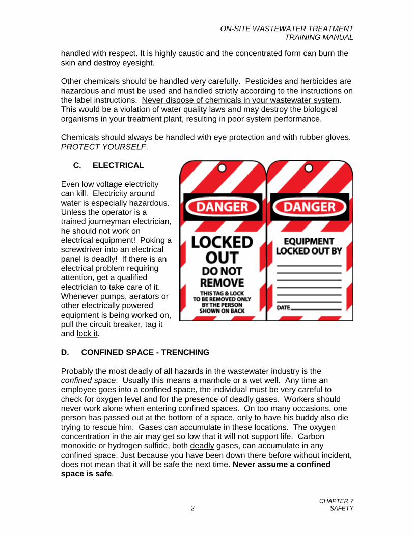
ON-SITE WASTEWATER TREATMENT TRAINING MANUAL
CHAPTER 7 2 SAFETY
handled with respect. It is highly caustic and the concentrated form can burn the skin and destroy eyesight. Other chemicals should be handled very carefully. Pesticides and herbicides are hazardous and must be used and handled strictly according to the instructions on the label instructions. Never dispose of chemicals in your wastewater system. This would be a violation of water quality laws and may destroy the biological organisms in your treatment plant, resulting in poor system performance. Chemicals should always be handled with eye protection and with rubber gloves. PROTECT YOURSELF.
C. ELECTRICAL Even low voltage electricity can kill. Electricity around water is especially hazardous. Unless the operator is a trained journeyman electrician, he should not work on electrical equipment! Poking a screwdriver into an electrical panel is deadly! If there is an electrical problem requiring attention, get a qualified electrician to take care of it. Whenever pumps, aerators or other electrically powered equipment is being worked on, pull the circuit breaker, tag it and lock it. D. CONFINED SPACE - TRENCHING Probably the most deadly of all hazards in the wastewater industry is the confined space. Usually this means a manhole or a wet well. Any time an employee goes into a confined space, the individual must be very careful to check for oxygen level and for the presence of deadly gases. Workers should never work alone when entering confined spaces. On too many occasions, one person has passed out at the bottom of a space, only to have his buddy also die trying to rescue him. Gases can accumulate in these locations. The oxygen concentration in the air may get so low that it will not support life. Carbon monoxide or hydrogen sulfide, both deadly gases, can accumulate in any confined space. Just because you have been down there before without incident, does not mean that it will be safe the next time. Never assume a confined space is safe.
ON-SITE WASTEWATER TREATMENT TRAINING MANUAL
CHAPTER 7 3 SAFETY
There are some important rules to know and understand to assure safety in trenching. Call the Safety Bureau of the Department of Labor and Industry (406-444-6401) to obtain the rules for workers who are engaged in trenching activities. E. PUMP STATIONS Pump stations (also known as lift stations), including small pump chambers, present hazards that employees should always be aware of when entering. A pump station is a confined space and the statements above apply to them. A pump station that can be entered must have a ventilation fan which automatically turns on when the manway lid is opened or when a light switch is turned on. Let the fan ventilate for a few minutes before entering. Be sure that the cover is completely back and secured. Ladders are easy to slip on, so make sure you have secure footing on each rung. Be very careful of electrical wiring and equipment as even 115V can be deadly in a wet area. Small pump chambers for on-site systems are generally not designed for human entry; maintenance of these units should always be done from the ground surface. General safety practices to observe around pumping equipment include the following:
Keep guards and shields in place Do not remove labels and tags during maintenance Pumps may be hot; approach them cautiously Do not pump against a closed valve or with a plugged suction
line Use lifting equipment designed for the job Insure power is OFF when working on the pump Use your O&M Manual Watch loose clothing and long hair around equipment Know what to do before working on a pump or motor
Entrance into a wet well of a pump station should be avoided if at all possible and operators should attempt to perform all maintenance work from above. If it is necessary to enter a wet well, the space must be adequately ventilated and the atmosphere tested before entering. Use a removable ladder for access and do not trust the manhole steps that may have been installed in the original construction of the wet well. Access should be made with the appropriate safety harness on the individual entering the space including the necessary means to lift the individual from the space. Any time an employee is performing work where a possible hazard may be present, use the buddy system. Have another employee present to help or to get help.
ON-SITE WASTEWATER TREATMENT TRAINING MANUAL
CHAPTER 7 4 SAFETY
F. SEPTIC TANKS When working near a septic tank with a lid or cover removed, use extreme caution to ensure proper flow of air near the tank opening. The atmosphere inside a tank is extremely toxic. Individuals have been known to have been overcome at the surface by odors coming from inside the tank. Ensure that footing is solid and that there is no chance of slipping and falling into the tank. Never enter a septic tank, even when empty. Use the buddy system whenever possible when performing maintenance or sampling tasks at the septic tank.
ON-SITE WASTEWATER TREATMENT TRAINING MANUAL
CHAPTER 7 5 SAFETY
SELF-STUDY QUESTIONS - CHAPTER 7 1. Proper safety procedures used to prevent the spread of germs that cause
waterborne diseases include:
(a) Washing your hands after each site visit and before eating or smoking (b) Washing your work clothes at home (c) Keeping a safe distance from fellow employees (d) All of the above
2. Which of the following safety hazards are commonly associated with subsurface disposal systems?
(a) Drowning (b) Poisonous or explosive gases (c) Pathogens (disease-causing microorganisms) (d) All of the above (e) b and c above
3. When you need to enter a lift station dry well compartment, you should
always:
(a) Secure the cover in the open position (b) Let the fan ventilate the compartment (c) Observe confined space safety rules (d) All of the above
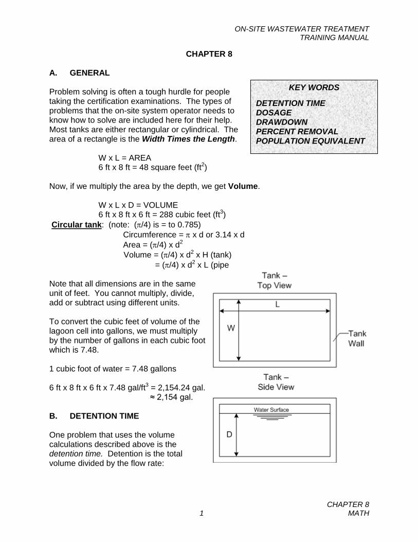
ON-SITE WASTEWATER TREATMENT TRAINING MANUAL
CHAPTER 8 1 MATH
CHAPTER 8 A. GENERAL Problem solving is often a tough hurdle for people taking the certification examinations. The types of problems that the on-site system operator needs to know how to solve are included here for their help. Most tanks are either rectangular or cylindrical. The area of a rectangle is the Width Times the Length.
W x L = AREA 6 ft x 8 ft = 48 square feet (ft2)
Now, if we multiply the area by the depth, we get Volume.
W x L x D = VOLUME 6 ft x 8 ft x 6 ft = 288 cubic feet (ft3)
Circular tank: (note: (π/4) is = to 0.785) Circumference = π x d or 3.14 x d Area = (π/4) x d2
Volume = (π/4) x d2 x H (tank) = (π/4) x d2 x L (pipe
Note that all dimensions are in the same unit of feet. You cannot multiply, divide, add or subtract using different units. To convert the cubic feet of volume of the lagoon cell into gallons, we must multiply by the number of gallons in each cubic foot which is 7.48. 1 cubic foot of water = 7.48 gallons 6 ft x 8 ft x 6 ft x 7.48 gal/ft3 = 2,154.24 gal. ≈ 2,154 gal. B. DETENTION TIME One problem that uses the volume calculations described above is the detention time. Detention is the total volume divided by the flow rate:
KEY WORDS DETENTION TIME DOSAGE DRAWDOWN PERCENT REMOVAL POPULATION EQUIVALENT
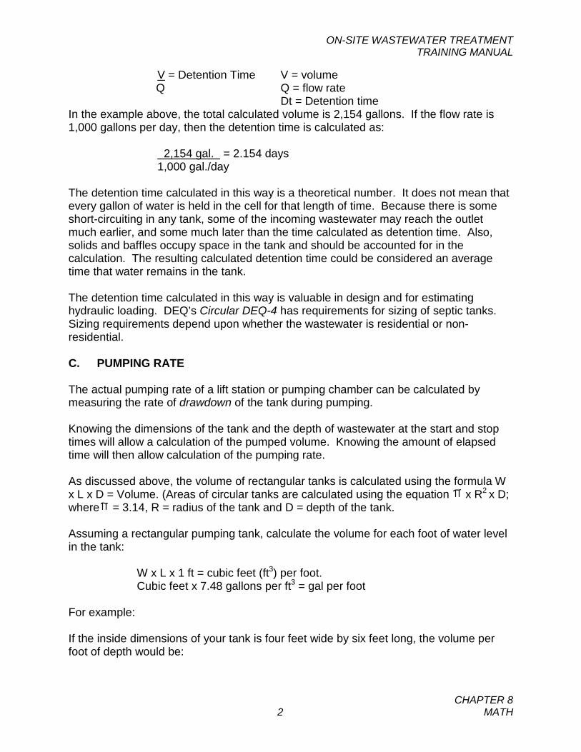
ON-SITE WASTEWATER TREATMENT TRAINING MANUAL
CHAPTER 8 2 MATH
V = Detention Time V = volume Q Q = flow rate Dt = Detention time
In the example above, the total calculated volume is 2,154 gallons. If the flow rate is 1,000 gallons per day, then the detention time is calculated as:
2,154 gal. = 2.154 days 1,000 gal./day
The detention time calculated in this way is a theoretical number. It does not mean that every gallon of water is held in the cell for that length of time. Because there is some short-circuiting in any tank, some of the incoming wastewater may reach the outlet much earlier, and some much later than the time calculated as detention time. Also, solids and baffles occupy space in the tank and should be accounted for in the calculation. The resulting calculated detention time could be considered an average time that water remains in the tank. The detention time calculated in this way is valuable in design and for estimating hydraulic loading. DEQ’s Circular DEQ-4 has requirements for sizing of septic tanks. Sizing requirements depend upon whether the wastewater is residential or non-residential. C. PUMPING RATE The actual pumping rate of a lift station or pumping chamber can be calculated by measuring the rate of drawdown of the tank during pumping. Knowing the dimensions of the tank and the depth of wastewater at the start and stop times will allow a calculation of the pumped volume. Knowing the amount of elapsed time will then allow calculation of the pumping rate. As discussed above, the volume of rectangular tanks is calculated using the formula W x L x D = Volume. (Areas of circular tanks are calculated using the equation x R2 x D; where = 3.14, R = radius of the tank and D = depth of the tank. Assuming a rectangular pumping tank, calculate the volume for each foot of water level in the tank:
W x L x 1 ft = cubic feet (ft3) per foot. Cubic feet x 7.48 gallons per ft3 = gal per foot
For example: If the inside dimensions of your tank is four feet wide by six feet long, the volume per foot of depth would be:
ON-SITE WASTEWATER TREATMENT TRAINING MANUAL
CHAPTER 8 3 MATH
4 ft x 6 ft x 1 ft = 24 ft3
24 ft3 x 7.48 gallons/CF = 179.5 or 180 gal/ft If it takes 10 minutes to drop the level of wastewater in the tank by four feet, then the pumping rate is:
180 gal/ft x 4 ft = 72 gallons per minute (gpm) 10 minutes
D. BOD and TSS REMOVAL One of the main reasons to treat wastewater in a lagoon is to reduce the amount of organic waste before allowing the water to flow into a stream. The organic waste is measured by the BOD test which is described in another part of this manual. Most discharge permits require an 85 percent removal in BOD and TSS. A standard formula for calculating pounds of anything if we know the concentration (mg/l) and flow rate is:
lbs/day = mg/l x million gal/day x 8.34 lb/gal
The number 8.34 is the weight in pounds of 1 gallon of water. To use this formula, first change the flow rate into millions of gallons per day. If the flow rate is in gallons per day, just divide by 1,000,000. 500,000 gallons per day would be 0.5 mgd, or 50,000 would be 0.05 mgd. If the flow rate is measured in gallons per minute, multiply by 1440 minutes per day and divide by 1,000,000. (60 min/hr x 24 hrs/day = 1440 min/day). Use the actual test number for mg/l. For example, if we have a raw sewage test of 220 mg/l BOD and the flow is 100,000 gallons per day, then the pounds of BOD coming into the treatment system is:
lbs/day = 220 mg/l x 0.1 mgd x 8.34 lbs/day = 183.5 lbs/day of BOD
Now, we can do the same calculation on the effluent. If we assume that the test on the discharge water (effluent) is 30 mg/l BOD going out of the system, and the flow is the same:
lbs of BOD = 30 mg/l x 0.1 mgd x 8.34 lb/gal lbs of BOD = 25 lbs/day of BOD.
The pounds of removal = 183.5 lbs - 25 lbs or 158.5 lbs The percent removal is = load in - load out x 100
total load
ON-SITE WASTEWATER TREATMENT TRAINING MANUAL
CHAPTER 8 4 MATH
= 158.5 lbs x 100 = 86.4 % removal
183.5 lbs
The same calculation can be used for TSS to determine the pounds coming in, the pounds going out, and percent removal. E. BOD PER CAPITA A standard number is used for design purposes to estimate the average amount of BOD contributed by each person in a community. This number is generally accepted as 0.20 pounds BOD per day per person. Therefore, a town of 1000 population would have a daily sewage load of approximately 200 pounds of BOD to treat. This number may vary in practice, but it is appropriate for domestic sewage without a high BOD source like a milk processing plant. This figure is called the BOD population equivalent. If you have the daily sewage flow and the average BOD for the raw sewage, you can calculate your own community population equivalent. Remember the standard formula for finding pounds.
Pounds per day = mg/l x million gallons per day (mgd) x 8.34 lb/gal
That will give you the pounds of BOD per day. Divide by your community population and you will have it. Example: 350,000 gal per day at 180 mg/l BOD
lbs BOD = 180 mg/l x .350 mgd x 8.34 lb/gal lbs BOD = 525.4 lbs.
If the population is 2900 people Population Equivalent = 525.4 = 0.18 lbs BOD/person
2900 F. DOSAGE The same formula for pounds of BOD can be used for any chemical dosage. If you need to calculate the amount of chlorine to add, this is the same formula. Use the dose of chlorine in mg/l. If you wish to add 3 mg/l of chlorine to your effluent, the lbs = mg/l x mgd x 8.34 will give the answer. In 150,000 gallons per day, it would be:
Pounds chlorine = 3.0 mg/l x 0.15 mgd x 8.34 lb/gal = 3.75 pounds chlorine per day.
Another form of this standard formula will give you the dosage if you know the pounds:
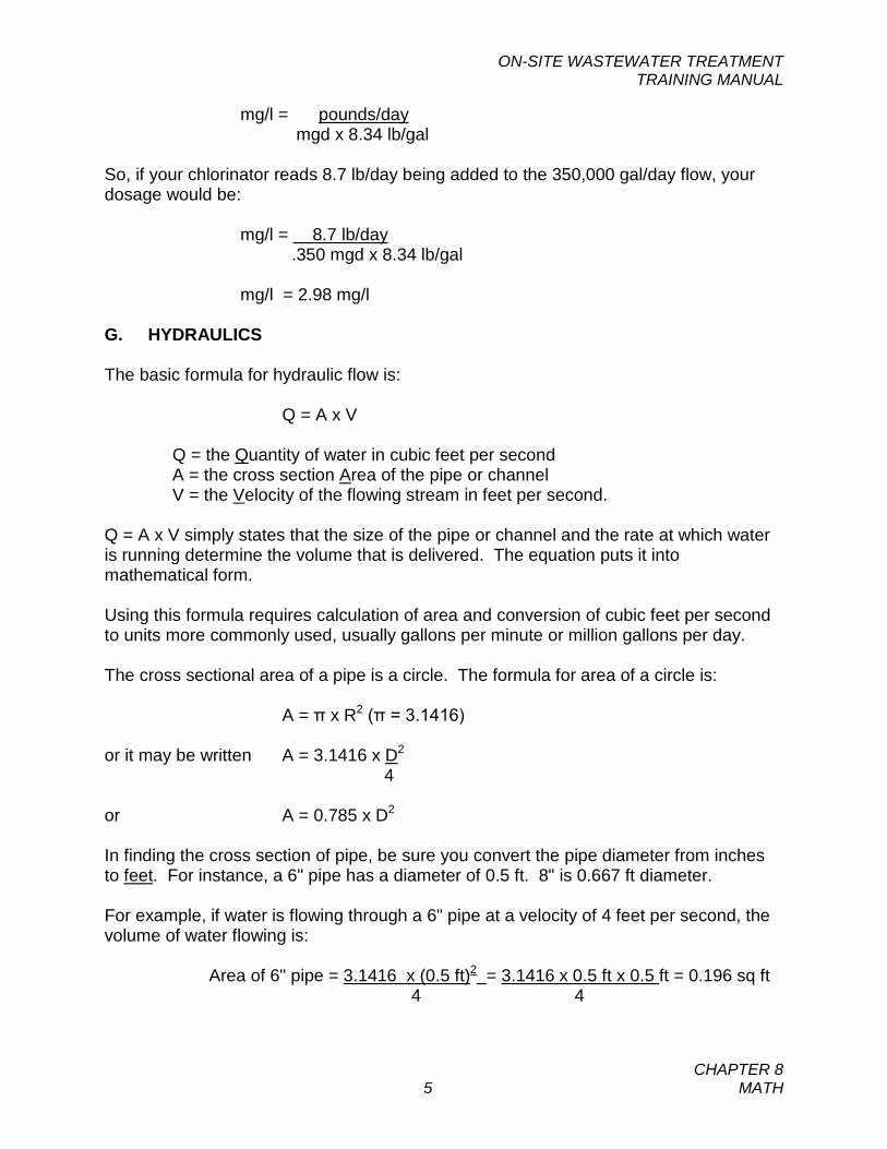
ON-SITE WASTEWATER TREATMENT TRAINING MANUAL
CHAPTER 8 5 MATH
mg/l = pounds/day mgd x 8.34 lb/gal
So, if your chlorinator reads 8.7 lb/day being added to the 350,000 gal/day flow, your dosage would be:
mg/l = 8.7 lb/day .350 mgd x 8.34 lb/gal
mg/l = 2.98 mg/l G. HYDRAULICS The basic formula for hydraulic flow is:
Q = A x V Q = the Quantity of water in cubic feet per second A = the cross section Area of the pipe or channel V = the Velocity of the flowing stream in feet per second. Q = A x V simply states that the size of the pipe or channel and the rate at which water is running determine the volume that is delivered. The equation puts it into mathematical form. Using this formula requires calculation of area and conversion of cubic feet per second to units more commonly used, usually gallons per minute or million gallons per day. The cross sectional area of a pipe is a circle. The formula for area of a circle is:
A = π x R2 (π = 3.1416) or it may be written A = 3.1416 x D2
4 or A = 0.785 x D2 In finding the cross section of pipe, be sure you convert the pipe diameter from inches to feet. For instance, a 6" pipe has a diameter of 0.5 ft. 8" is 0.667 ft diameter. For example, if water is flowing through a 6" pipe at a velocity of 4 feet per second, the volume of water flowing is:
Area of 6" pipe = 3.1416 x (0.5 ft)2 = 3.1416 x 0.5 ft x 0.5 ft = 0.196 sq ft 4 4
ON-SITE WASTEWATER TREATMENT TRAINING MANUAL
CHAPTER 8 6 MATH
volume = A x V = 0.196 sq ft x 4 ft/sec = 0.785 cubic feet per second.
As there are 7.48 gallons in each cubic ft, and there are 60 seconds in each minute, this flow rate can be converted to gal per minute by multiplying:
GPM = 0.785 CFS x 7.48 gal/CF x 60 sec/min = 352 gallons per minute
Flow in a rectangular shaped channel can be calculated by multiplying the velocity of the flowing stream by the channel area (calculated as width x depth of flow). The formula sheet developed by the DEQ for assisting operators in solving math problems is found in Appendix D, following the self-study questions. These formulas should be used and understood by the operator in preparation for the Certification Exam.
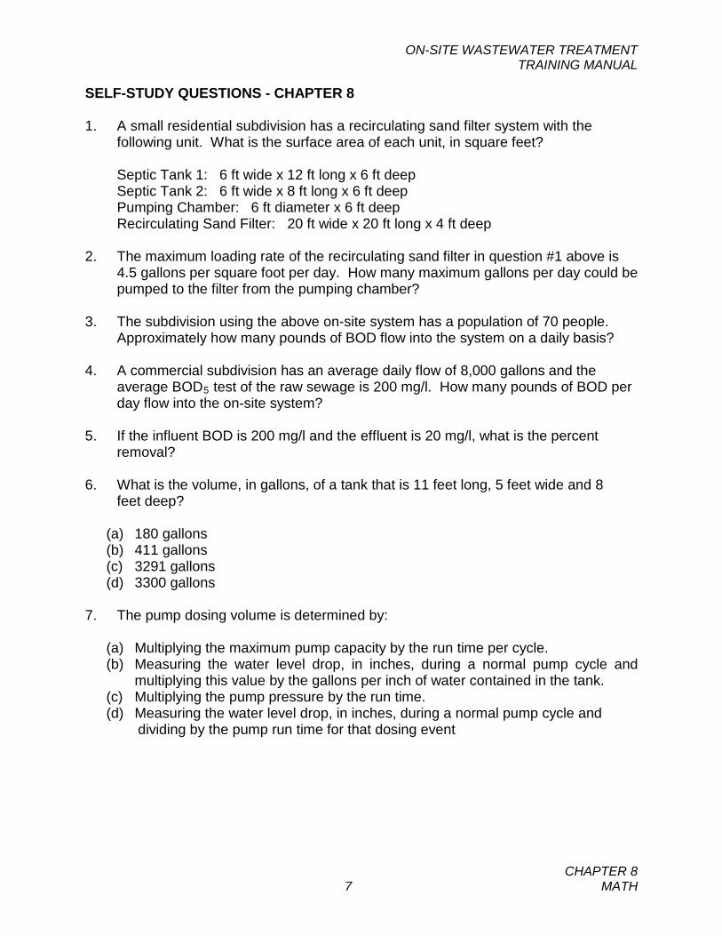
ON-SITE WASTEWATER TREATMENT TRAINING MANUAL
CHAPTER 8 7 MATH
SELF-STUDY QUESTIONS - CHAPTER 8 1. A small residential subdivision has a recirculating sand filter system with the
following unit. What is the surface area of each unit, in square feet?
Septic Tank 1: 6 ft wide x 12 ft long x 6 ft deep Septic Tank 2: 6 ft wide x 8 ft long x 6 ft deep Pumping Chamber: 6 ft diameter x 6 ft deep Recirculating Sand Filter: 20 ft wide x 20 ft long x 4 ft deep
2. The maximum loading rate of the recirculating sand filter in question #1 above is
4.5 gallons per square foot per day. How many maximum gallons per day could be pumped to the filter from the pumping chamber?
3. The subdivision using the above on-site system has a population of 70 people.
Approximately how many pounds of BOD flow into the system on a daily basis? 4. A commercial subdivision has an average daily flow of 8,000 gallons and the
average BOD5 test of the raw sewage is 200 mg/l. How many pounds of BOD per day flow into the on-site system?
5. If the influent BOD is 200 mg/l and the effluent is 20 mg/l, what is the percent
removal? 6. What is the volume, in gallons, of a tank that is 11 feet long, 5 feet wide and 8 feet deep?
(a) 180 gallons (b) 411 gallons (c) 3291 gallons (d) 3300 gallons
7. The pump dosing volume is determined by:
(a) Multiplying the maximum pump capacity by the run time per cycle. (b) Measuring the water level drop, in inches, during a normal pump cycle and
multiplying this value by the gallons per inch of water contained in the tank. (c) Multiplying the pump pressure by the run time. (d) Measuring the water level drop, in inches, during a normal pump cycle and dividing by the pump run time for that dosing event
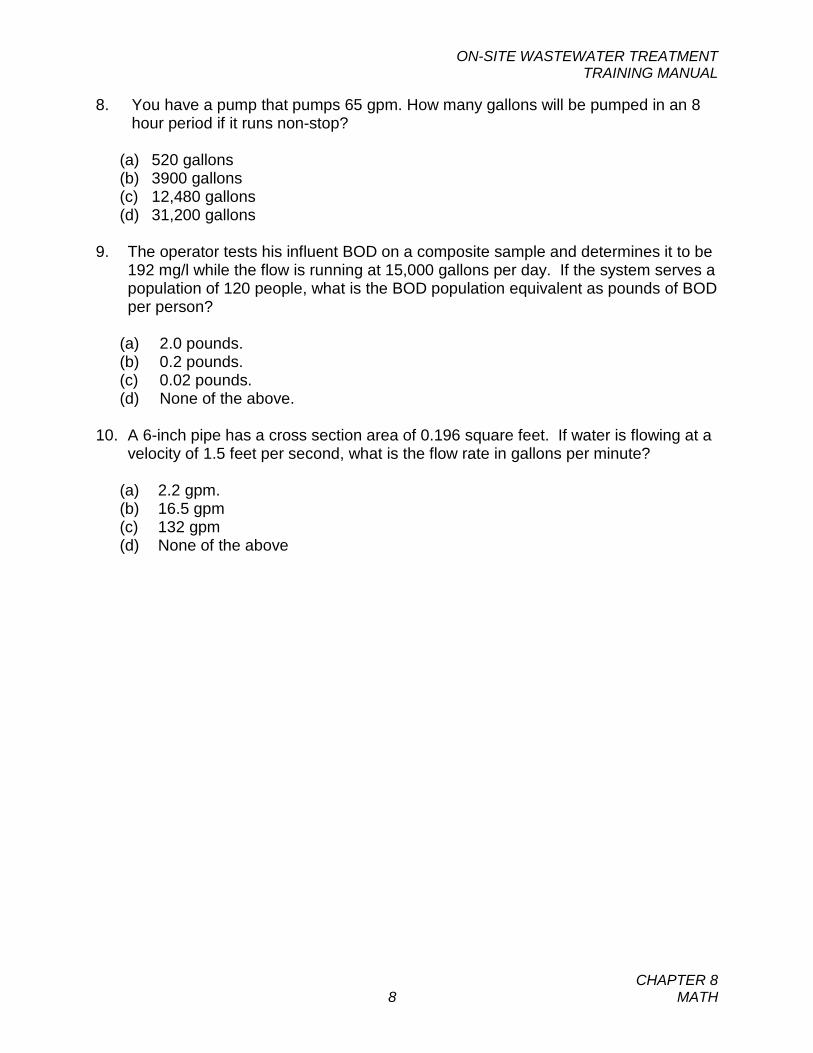
ON-SITE WASTEWATER TREATMENT TRAINING MANUAL
CHAPTER 8 8 MATH
8. You have a pump that pumps 65 gpm. How many gallons will be pumped in an 8 hour period if it runs non-stop?
(a) 520 gallons (b) 3900 gallons (c) 12,480 gallons (d) 31,200 gallons
9. The operator tests his influent BOD on a composite sample and determines it to be
192 mg/l while the flow is running at 15,000 gallons per day. If the system serves a population of 120 people, what is the BOD population equivalent as pounds of BOD per person?
(a) 2.0 pounds. (b) 0.2 pounds. (c) 0.02 pounds. (d) None of the above.
10. A 6-inch pipe has a cross section area of 0.196 square feet. If water is flowing at a
velocity of 1.5 feet per second, what is the flow rate in gallons per minute?
(a) 2.2 gpm. (b) 16.5 gpm (c) 132 gpm (d) None of the above
APPENDICES
Appendix A – Answers to Self-Study Questions Appendix B – Glossary of Terms Appendix C – Example of Discharge Monitoring
Report Appendix D – Formula Sheet

APPENDIX A
Answers to Self-Study Questions
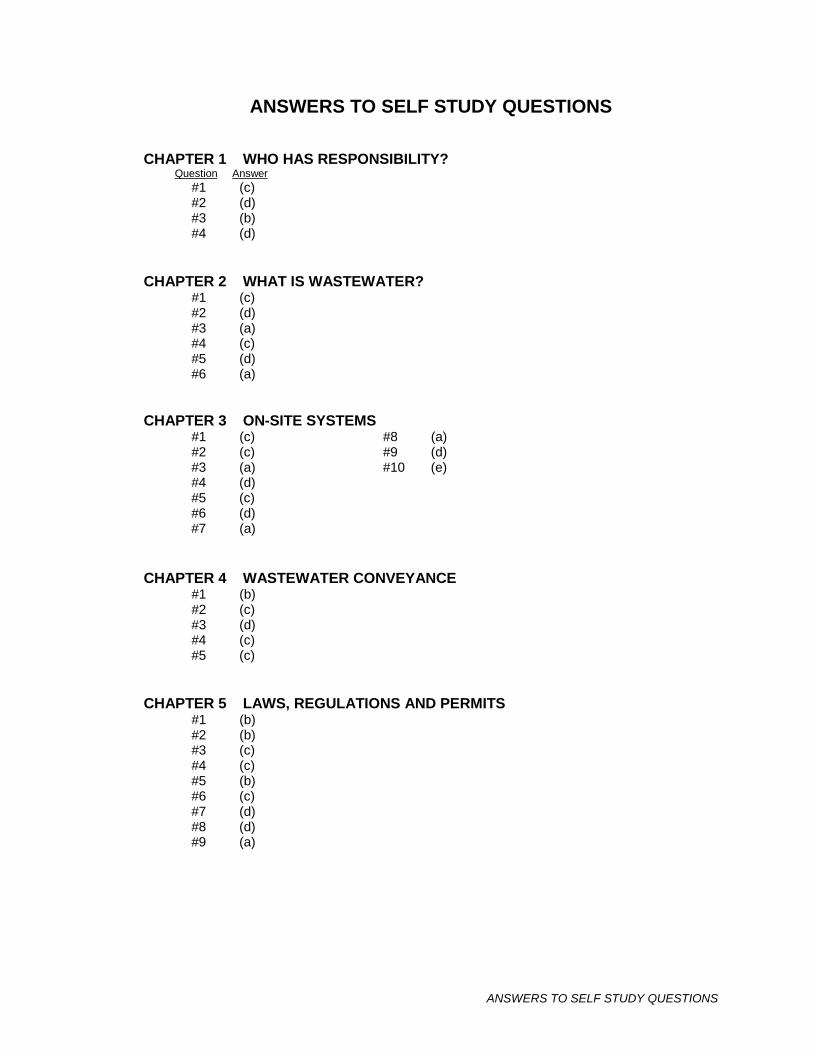
ANSWERS TO SELF STUDY QUESTIONS
ANSWERS TO SELF STUDY QUESTIONS CHAPTER 1 WHO HAS RESPONSIBILITY?
Question Answer #1 (c) #2 (d) #3 (b) #4 (d)
CHAPTER 2 WHAT IS WASTEWATER?
#1 (c) #2 (d) #3 (a)
#4 (c) #5 (d) #6 (a)
CHAPTER 3 ON-SITE SYSTEMS #1 (c) #8 (a)
#2 (c) #9 (d) #3 (a) #10 (e)
#4 (d) #5 (c) #6 (d) #7 (a)
CHAPTER 4 WASTEWATER CONVEYANCE
#1 (b) #2 (c) #3 (d)
#4 (c) #5 (c)
CHAPTER 5 LAWS, REGULATIONS AND PERMITS
#1 (b) #2 (b) #3 (c)
#4 (c) #5 (b) #6 (c) #7 (d) #8 (d) #9 (a)
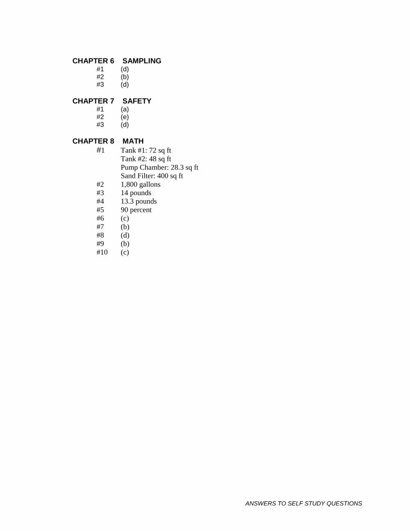
ANSWERS TO SELF STUDY QUESTIONS
CHAPTER 6 SAMPLING
#1 (d) #2 (b) #3 (d)
CHAPTER 7 SAFETY #1 (a)
#2 (e) #3 (d)
CHAPTER 8 MATH
#1 Tank #1: 72 sq ft Tank #2: 48 sq ft Pump Chamber: 28.3 sq ft Sand Filter: 400 sq ft
#2 1,800 gallons #3 14 pounds #4 13.3 pounds #5 90 percent #6 (c) #7 (b) #8 (d) #9 (b) #10 (c)
APPENDIX B
On-Site Wastewater Terms
On-Site Wastewater Terms
1
ON-SITE WASTEWATER TERMS (from Circular DEQ-4)
Absorption area means that area determined by multiplying the length and width of the bottom area of the disposal trench. Absorption bed means an absorption system that consists of excavations greater than 3 feet in width where the distribution system is laid for the purpose of distributing pretreated waste effluent into the ground. Absorption system means any secondary treatment system including absorption trenches, elevated sand mounds, and evapotranspiration absorption (ETA) systems used for subsurface disposal of pretreated waste effluent. Absorption trench means an absorption system that consists of excavations less than or equal to 3 feet in width where the distribution system is laid for the purpose of distributing pretreated waste effluent into the ground. Advanced treatment means a treatment process that provides effluent quality in excess of primary treatment. Aerobic wastewater treatment unit means a wastewater treatment plant that incorporates a means of introducing air and oxygen into the wastewater so as to provide aerobic biochemical stabilization during detention period. Aerobic wastewater treatment facilities may include anaerobic processes as part of the treatment system. Bedrock mean material that cannot be readily excavated by hand tools, or material that does not allow water to pass through or that has insufficient quantities of fines to provide for the adequate treatment and disposal of wastewater. Bedroom means any room that is or may be used for sleeping. An unfinished basement is considered as an additional bedroom. BOD5 (five-day biochemical oxygen demand) means the quantity of oxygen used in the biochemical oxidation of organic matter in 5 days at 20 degrees centigrade under specified conditions and reported as milligrams per liter (mg/L). Building drain means the pipe extending from the interior plumbing to a point 2 feet outside the foundation wall. Building sewer means the pipe connecting the house or building drain to the public sewer or private sewer. Cleanout means an access to a sewer line at least 4 inches in diameter, extending from the sewer line to the ground surface or inside the foundation, used for access to clean a sewer line. Chemical nutrient reduction means a wastewater treatment system that incorporates the systematic addition of one or more chemicals into the effluent in order to reduce the concentration of one or more chemical components (such as nitrate or phosphorus).
On-Site Wastewater Terms
2
Design flow means the peak flow (daily or instantaneous, as appropriate) for sizing hydraulic facilities, such as pumps, piping, storage, and absorption systems and means the average daily flow for sizing other treatment systems. Distribution box means a watertight receptacle that receives septic tank effluent and distributes it equally into two or more pipes leading to the absorption area. Distribution pipe means a perforated pipe used in the dispersion of septic tank or other treatment facility effluent into disposal trenches, seepage trenches, or seepage beds. Dosing frequency means the number of times per day that effluent is applied to an absorption system, drainfield, sand filter, or sand mound, or to a section of an absorption system, drainfield, sand filter, or sand mound. Dosing tank means a watertight receptacle receiving effluent from the septic tank or after another treatment device, equipped with an automatic siphon or pump designed to discharge effluent. Dosing volume means the volume of effluent (in gallons) applied to an absorption system, drainfield, sand filter, or sand mound each time a pump is turned on or each time a siphon functions. Drain rock means the rock or coarse aggregate used in an absorption system, drainfield, sand mound or sand filter. Drain rock must be washed, be a maximum of 2 ½ inches in diameter and larger than the orifice size unless shielding is provided to protect the orifice, and contain no more than 2 percent passing the No. 8 sieve. The material must be of sufficient competency to resist slaking or dissolution. Gravels of shale, sandstone, or limestone may degrade and may not be used. Dwelling or residence means any structure, building, or portion thereof, which is intended or designed for human occupancy and supplied with water by a piped water system. Effective size means the sieve size in millimeters (mm) allowing only 10 percent of the material to pass as determined by wet-test sieve analysis method ASTM C117-95. Effluent means partially treated wastewater from a septic tank or other treatment facility. Effluent filter means an effluent treatment device installed on the outlet of a septic tank designed to prevent the passage of suspended matter larger than 1/8 inch in size. Fats, oils, grease (FOG) means a component of wastewater typically originating from food stuffs (animal fats or vegetable oils) or consisting of compounds of alcohol or glycerol with fatty acids (soaps and lotions). Gravity dose means a known volume (dose) of effluent that is delivered to an absorption system in a specific time interval. The effluent may be delivered either by a siphon or by a pump to a distribution box or manifold. Gray water -wastewater that is collected separately from a sewage flow and that does not contain industrial chemicals, hazardous wastes, or wastewater from toilets.
On-Site Wastewater Terms
3
Grease trap means a device designed to separate grease and oils from the effluent. High-strength waste means effluent from a septic tank or other treatment device that has BOD5 greater than 300 mg/L, and/or TSS greater than 150mg/L, and/or fats, oils, and grease greater than 25mg/L. Impervious layer means any layer of material in the soil profile that has a percolation rate slower than 120 minutes per inch. Individual wastewater system means a wastewater system that serves one living unit or commercial structure. The total number of people served may not exceed 24. Infiltrative surface means the soil interface that receives the effluent wastewater below the drain rock or sand. Influent means the wastewater flow stream prior to any treatment. Irrigation – Irrigation systems are those that provide for the subsurface application of wastewater to any planted material by means of a piping system. Manhole means an access to a sewer line for cleaning or repair, with requirements as defined in Department Circular DEQ-2, 1999 Edition. Manifold means a solid (nonperforated) main wastewater line that distributes effluent to individual distribution pipes. Monitoring well means a well that is used for pollutant recovery or monitoring ground water quality, ground water levels, or flow direction, but whose primary purpose is not the withdrawal or acquisition of ground water. Multiple-user wastewater system means a nonpublic wastewater system that serves, or is intended to serve, three through 14 living units or three through 14 commercial structures. The total population served may not exceed 24. In estimating the population served, the reviewing authority shall multiply the number of living units times the county average of persons per living unit based on the most recent census data. Passive nutrient reduction means a wastewater treatment system, other than elevated sand mound, intermittent sand filter, or recirculating sand filter that reduces the effluent concentration of one or more components (such as nitrate or phosphorus) without the addition of chemicals and without mechanical aeration. Percolation test means a standardized test used to assess the infiltration rate of soils. Pressure distribution means an effluent distribution system where all pipes are pressurized, the head at any orifice is at least 1 pound per square inch (psi) and not more than 6 psi, and the effluent is pumped (or delivered by siphon) to the next portion of the treatment system in a specific time interval. Pretreatment means the wastewater treatment that takes place prior to discharging to any component of a wastewater treatment and disposal system, including, but not limited to, pH adjustment, oil and grease removal, BOD5 and TSS reduction, screening, and
On-Site Wastewater Terms
4
detoxification. Primary treatment means a treatment system that provides retention time to settle the solids in raw wastewater and that retains scum within the system. Private sewer means a sewer receiving the discharge from one building sewer and conveying it to the public sewer system or a wastewater treatment system. Public wastewater system means a system for collection, transportation, treatment, or disposal of wastewater that serves 15 or more families or 25 or more persons daily for a period of at least 60 days in a calendar year. In estimating the population served, the reviewing authority shall multiply the number of living units times the county average of persons per living unit based on the most recent census data. Residential strength wastewater means effluent from a septic tank or other treatment device with a BOD5 less than or equal to 300 mg/L, TSS less than or equal to 150 mg/L, and fats, oils, and grease less than or equal to 25 mg/L. Reviewing authority means the Department of Environmental Quality, a local department or board of health certified conduct review under 76-4-104, MCA; a division of local government delegated to review public wastewater systems pursuant to ARM 17.38.102; a local unit of government that has adopted these standards pursuant to 76-3-504, MCA; or a local board of health that has adopted these standards pursuant to 50-2-116, MCA. Secondary treatment means a biological treatment process coupled with solid/liquid separation. The effluent from secondary treatment should generally have a BOD5 less than 30 mg/L and TSS less than 30 mg/L. Septic tank means a storage settling tank in which settled sludge is in immediate contact with the wastewater flowing through the tank while the organic solids are decomposed by anaerobic action. Sewage is synonymous with “wastewater” for purposes of this circular. Sewer invert means inside bottom (or flow line) of a sewer pipe. Shared wastewater system means a wastewater system that serves or is intended to serve two living units or commercial structures. The total number of people served may not exceed 24. In estimating the population served, the reviewing authority shall multiply the number of living units times the county average of persons per living unit based on the most recent census data. Siphon means a pipe fashioned in an inverted U shape and filled until atmospheric pressure is sufficient to force a liquid from a reservoir in one end of the pipe over a barrier and out the other end. Siphons are sometimes used to gravity-dose an absorption system from a dosing tank or chamber.
On-Site Wastewater Terms
5
State Waters means a body of water, irrigation system, or drainage system, either surface or underground. The term does not apply to:
i. ponds or lagoons used solely for treating, transporting, or impounding pollutants; or
ii. irrigation water or land application disposal water when the waters are used up within the irrigation or land application disposal system and the waters are not returned to state waters.
Surge Tank means a watertight structure or container that is part of a gray water irrigation system. Synthetic drainage fabric means a nonwoven drainage fabric with a minimum weight per square yard of 4 ounces, a water flow rate of 100 to 200 gallons per minute per square foot and an apparent opening size equivalent to a No. 50 to No. 110 sieve. Tertiary treatment means additional removal of colloidal and suspended solids by chemical coagulation and/or medium filtration for the reduction of nutrients. TSS (Total Suspended Solids) means solids in wastewater that can be removed by standard filtering procedures in a laboratory and is reported as milligrams per liter (mg/L). Uniformity coefficient (UC) means the sieve size in millimeters (mm) that allows 60 percent of the material to pass (D60), divided by the sieve size in mm allowing 10 percent of the material to pass (D10), as determined by ASTM C117-95 (UC=D60/D10). Uniform distribution is a means to distribute effluent into a sand filter, sand mound, or absorption system such that the difference in flow (measured in gallons per day per square foot) throughout the absorption system, sand filter, or sand mound is less than 10 percent. Waste Segregation – Waste segregation systems consist of dry disposal of toilet waste by a method such as composting, chemical, dehydrating, or incinerator treatment, with a separate disposal method for gray water. Wastewater means water-carried waste that is discharged from a dwelling, building, or other facility, including household, commercial, or industrial wastes; chemicals; human excreta; or animal and vegetable matter in suspension or solution.
APPENDIX C
Example of
Discharge Monitoring Report
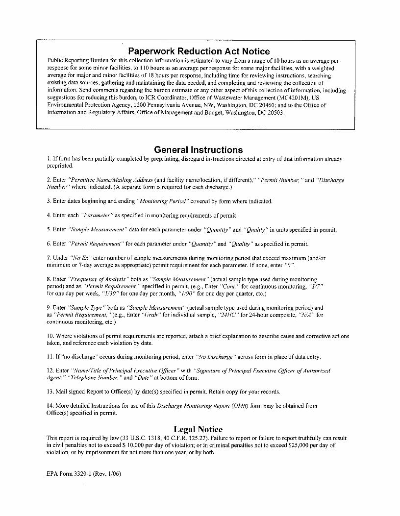
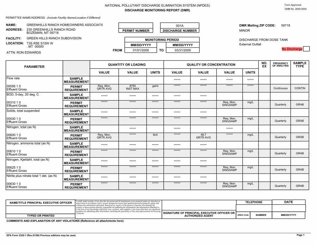
NATIONAL POLLUTANT DISCHARGE ELIMINATION SYSTEM (NPDES)DISCHARGE MONITORING REPORT (DMR)
Form Approved
OMB No. 20400004
PERMITTEE NAME/ADDRESS (Include Facility Name/Location if Different)
MONITORING PERIODMM/DD/YYYY MM/DD/YYYY
FROM 01/01/2009 TO 03/31/2009
001ADISCHARGE NUMBERPERMIT NUMBER
DMR Mailing ZIP CODE: 59718MINOR DISCHARGE FROM DOSE TANKExternal Outfall
No Discharge
NAME:ADDRESS:
FACILITY:LOCATION:
GREENHILLS RANCH HOMEOWNERS ASSOCIATION235 GREENHILLS RANCH ROADBOZEMAN, MT 59718
GREEN HILLS RANCH SUBDIVISIONT3S R5E S15W W, MT 00000
ATTN: RON EDWARDS
PARAMETER QUANTITY OR LOADING QUALITY OR CONCENTRATION NO.EX
FREQUENCYOF ANALYSIS
SAMPLETYPE
VALUE VALUE UNITS VALUE VALUE VALUE UNITS
Flow rate SAMPLEMEASUREMENT ****** ****** ****** ******
00056 1 0Effluent Gross
PERMITREQUIREMENT
Req. Mon.QRTR AVG
8750INST MAX
gal/d ****** ****** ****** ******Continuous CONTIN
BOD, 5day, 20 deg. C SAMPLEMEASUREMENT ****** ****** ****** ****** ******
00310 1 0Effluent Gross
PERMITREQUIREMENT
****** ****** ****** ****** ****** Req. Mon.SINGSAMP
mg/LQuarterly GRAB
Solids, total suspended SAMPLEMEASUREMENT ****** ****** ****** ****** ******
00530 1 0Effluent Gross
PERMITREQUIREMENT
****** ****** ****** ****** ****** Req. Mon.SINGSAMP
mg/LQuarterly GRAB
Nitrogen, total (as N) SAMPLEMEASUREMENT ****** ****** ******
00600 1 0Effluent Gross
PERMITREQUIREMENT
Req. Mon.QRTR AVG
****** lb/d ****** 48.7QRTR AVG
****** mg/LQuarterly GRAB
Nitrogen, ammonia total (as N) SAMPLEMEASUREMENT ****** ****** ****** ****** ******
00610 1 0Effluent Gross
PERMITREQUIREMENT
****** ****** ****** ****** ****** Req. Mon.SINGSAMP
mg/LQuarterly GRAB
Nitrogen, Kjeldahl, total (as N) SAMPLEMEASUREMENT ****** ****** ****** ****** ******
00625 1 0Effluent Gross
PERMITREQUIREMENT
****** ****** ****** ****** ****** Req. Mon.SINGSAMP
mg/LQuarterly GRAB
Nitrite plus nitrate total 1 det. (as N) SAMPLEMEASUREMENT ****** ****** ****** ****** ******
00630 1 0Effluent Gross
PERMITREQUIREMENT
****** ****** ****** ****** ****** Req. Mon.SINGSAMP
mg/LQuarterly GRAB
TELEPHONE
COMMENTS AND EXPLANATION OF ANY VIOLATIONS (Reference all attachments here)
NAME/TITLE PRINCIPAL EXECUTIVE OFFICER
TYPED OR PRINTED
DATEI certify under penalty of law that this document and all attachments were prepared under my direction orsupervision in accordance with a system designed to assure that qualified personnel properly gather andevaluate the information submitted. Based on my inquiry of the person or persons who manage thesystem, or those persons directly responsible for gathering the information, the information submitted is,to the best of my knowledge and belief, true, accurate, and complete. I am aware that there are significantpenalties for submitting false information, including the possibility of fine and imprisonment for knowingviolations. SIGNATURE OF PRINCIPAL EXECUTIVE OFFICER OR
AUTHORIZED AGENT AREA Code NUMBER MM/DD/YYYY
EPA Form 33201 (Rev.01/06) Previous editions may be used. Page 1

APPENDIX D
Math Formula Sheet
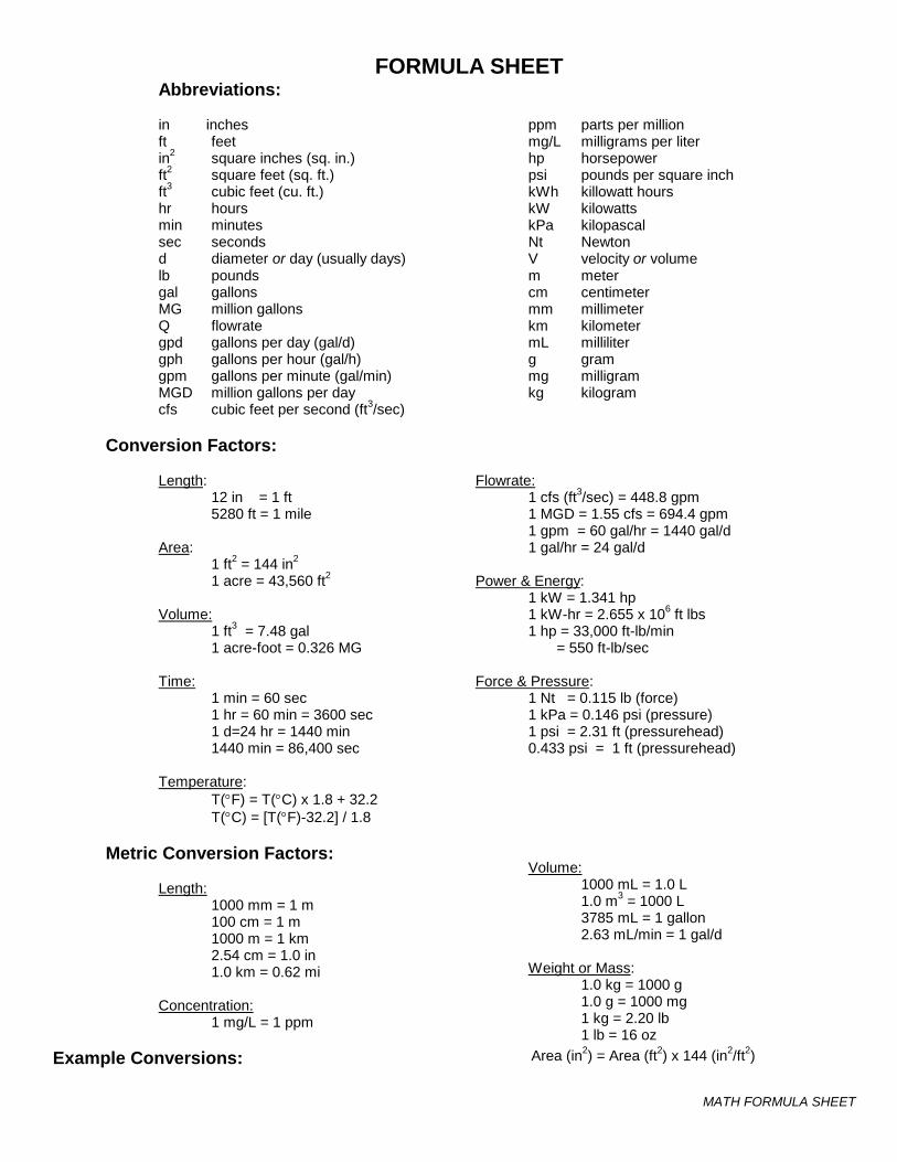
MATH FORMULA SHEET
FORMULA SHEET Abbreviations:
in inches ft feet in2 square inches (sq. in.) ft2 square feet (sq. ft.) ft3 cubic feet (cu. ft.) hr hours min minutes sec seconds d diameter or day (usually days) lb pounds gal gallons MG million gallons Q flowrate gpd gallons per day (gal/d) gph gallons per hour (gal/h) gpm gallons per minute (gal/min) MGD million gallons per day cfs cubic feet per second (ft3/sec)
ppm parts per million mg/L milligrams per liter hp horsepower psi pounds per square inch kWh killowatt hours kW kilowatts kPa kilopascal Nt Newton V velocity or volume m meter cm centimeter mm millimeter km kilometer mL milliliter g gram mg milligram kg kilogram
Conversion Factors:
Length: 12 in = 1 ft 5280 ft = 1 mile
Area:
1 ft2 = 144 in2 1 acre = 43,560 ft2
Volume:
1 ft3 = 7.48 gal 1 acre-foot = 0.326 MG
Time:
1 min = 60 sec 1 hr = 60 min = 3600 sec 1 d=24 hr = 1440 min 1440 min = 86,400 sec
Temperature:
T(°F) = T(°C) x 1.8 + 32.2 T(°C) = [T(°F)-32.2] / 1.8
Flowrate: 1 cfs (ft3/sec) = 448.8 gpm 1 MGD = 1.55 cfs = 694.4 gpm 1 gpm = 60 gal/hr = 1440 gal/d 1 gal/hr = 24 gal/d
Power & Energy:
1 kW = 1.341 hp 1 kW-hr = 2.655 x 106 ft lbs 1 hp = 33,000 ft-lb/min = 550 ft-lb/sec
Force & Pressure:
1 Nt = 0.115 lb (force) 1 kPa = 0.146 psi (pressure) 1 psi = 2.31 ft (pressurehead) 0.433 psi = 1 ft (pressurehead)
Metric Conversion Factors:
Length: 1000 mm = 1 m 100 cm = 1 m 1000 m = 1 km 2.54 cm = 1.0 in 1.0 km = 0.62 mi
Concentration:
1 mg/L = 1 ppm
Volume:
1000 mL = 1.0 L 1.0 m3 = 1000 L 3785 mL = 1 gallon 2.63 mL/min = 1 gal/d
Weight or Mass:
1.0 kg = 1000 g 1.0 g = 1000 mg 1 kg = 2.20 lb 1 lb = 16 oz
Example Conversions:
Area (in2) = Area (ft2) x 144 (in2/ft2)
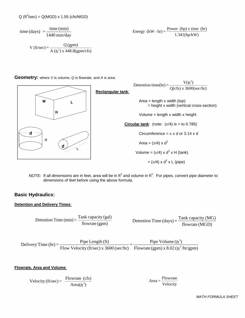
MATH FORMULA SHEET
Q (ft3/sec) = Q(MGD) x 1.55 (cfs/MGD)
Geometry: where V is volume, Q is flowrate, and A is area. Rectangular tank:
Area = length x width (top) = height x width (vertical cross-section)
Volume = length x width x height
Circular tank: (note: (π/4) is = to 0.785)
Circumference = π x d or 3.14 x d
Area = (π/4) x d2
Volume = (π/4) x d2 x H (tank)
= (π/4) x d2 x L (pipe)
NOTE: If all dimensions are in feet, area will be in ft2 and volume in ft3. For pipes, convert pipe diameter to dimensions of feet before using the above formula.
Basic Hydraulics: Detention and Delivery Times:
Flowrate, Area and Volume:
min/day 1440(min) time(days) time =
W)1.341(hp/k(hr) x time(hp)Power = hr)-(kWEnergy
cfs)448.8(gpm/ x )ft(A (gpm) Q = (ft/sec) V
2
r)3600(sec/hx Q(cfs))ftV( = time(hr)Detention
3
d
d
(MGD) flowrate(MG)capacity Tank = (days) Time Detention (gpm) flowrate
(gal)capacity Tank = (min) TimeDetention
VelocityFlowrate = Area
/hr/gpm)ft( 8.02 x (gpm) Flowrate)ft( Volume Pipe =
(sec/hr) 3600 x (ft/sec)Velocity Flow(ft)Length Pipe = (hr) TimeDelivery
3
3
)ftArea((cfs) Flowrate = (ft/sec)Velocity 2
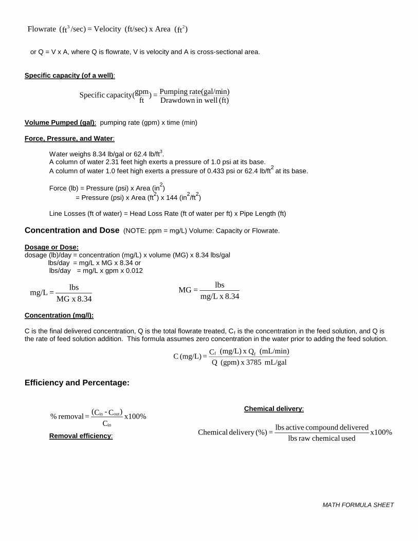
MATH FORMULA SHEET
or Q = V x A, where Q is flowrate, V is velocity and A is cross-sectional area. Specific capacity (of a well): Volume Pumped (gal): pumping rate (gpm) x time (min)
Force, Pressure, and Water:
Water weighs 8.34 lb/gal or 62.4 lb/ft3. A column of water 2.31 feet high exerts a pressure of 1.0 psi at its base. A column of water 1.0 feet high exerts a pressure of 0.433 psi or 62.4 lb/ft2 at its base.
Force (lb) = Pressure (psi) x Area (in2) = Pressure (psi) x Area (ft2) x 144 (in2/ft2)
Line Losses (ft of water) = Head Loss Rate (ft of water per ft) x Pipe Length (ft)
Concentration and Dose (NOTE: ppm = mg/L) Volume: Capacity or Flowrate. Dosage or Dose:dosage (lb)/day = concentration (mg/L) x volume (MG) x 8.34 lbs/gal lbs/day = mg/L x MG x 8.34 or lbs/day = mg/L x gpm x 0.012
Concentration (mg/l):
C is the final delivered concentration, Q is the total flowrate treated, Cf is the concentration in the feed solution, and Q is the rate of feed solution addition. This formula assumes zero concentration in the water prior to adding the feed solution.
Efficiency and Percentage:
Removal efficiency:
Chemical delivery:
)ft(Area x (ft/sec)Velocity = /sec)ft( Flowrate 23
(ft) in wellDrawdown in)rate(gal/m Pumping = )
ftgpmcapacity( Specific
8.34MG x lbs = mg/L
mL/gal 3785 x (gpm) Q(mL/min) Q x (mg/L) C = (mg/L) C ff
x100%C
)C - C( = removal %in
outin
x100%used chemical raw lbsdelivered compound active lbs = (%)delivery Chemical
8.34 x mg/Llbs =MG
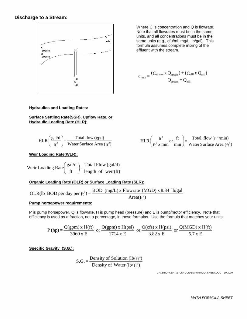
MATH FORMULA SHEET
Discharge to a Stream:
Hydraulics and Loading Rates: Surface Settling Rate(SSR), Upflow Rate, or Hydraulic Loading Rate (HLR):
Where C is concentration and Q is flowrate. Note that all flowrates must be in the same units, and all concentrations must be in the same units (e.g., cfu/ml, mg/L, lb/gal). This formula assumes complete mixing of the effluent with the stream.
Weir Loading Rate(WLR):
Organic Loading Rate (OLR) or Surface Loading Rate (SLR):
Pump horsepower requirements:
P is pump horsepower, Q is flowrate, H is pump head (pressure) and E is pump/motor efficiency. Note that efficiency is used as a fraction, not a percentage, in these formulas. Use the formula that matches your units.
Specific Gravity (S.G.):
G:\CSB\OPCERT\STUDYGUIDES\FORMULA SHEET.DOC 10/2000
Q + Q)QxC( + )QxC( = C
efflstream
efflefflstreamstreammix
)ft(Area SurfaceWater /min)ft(flow Total =
minftor
min ftft HLR
2
3
2
3
x
)ft(Area SurfaceWater
(gpd)flow Total = ft
gal/d HLR22
weir(ft)of length(gal/d) Flow Total =
ft gal/d RatengWeir Loadi
)ftArea(lb/gal 8.34x (MGD) x Flowrate (mg/L) BOD = )ftper day per BODOLR(lb 2
2
)ft(lb/ Water ofDensity )ft(lb/Solution ofDensity = S.G.
3
3
x E 5.7x H(ft) Q(MGD)or
x E 3.82x H(psi) Q(cfs)or
x E 1714x H(psi) Q(gpm)or
x E 3960x H(ft) Q(gpm) = (hp) P