Embed Size (px)
Citation preview
WASHING MACHINE (TOP-LOADING) CONTENTS
SERVICE Manual
WASHING MACHINETOP-LOADING TYPEBasic Name WA48H7400AW (WA7000H PJT)Basic Code WA48H7400AWA2Model Name WA48J7700AW WA48J7770AP WA48J7770AW (WA7700J PJT)Model Code WA48J7700AWA2 WA48J7770APA2 WA48J7770AWA2
1 Safety Instructions
2FeaturesandSpecifications
3 Disassembly and Reassembly
4 Troubleshooting
5 PCB Diagram
6 Wiring Diagram
7 Reference
CoNTeNTS
1 Safety instructions 11-1 Safety instructions for service engineers 1
2 FeaturesandSpecifications 52-1 Features 52-2 Specifications 62-3 Detail features 72-4 Optionsspecifications 8
3 Disassembly and Reassembly 93-1 Tools for disassembly and reassembly 93-2 Standard disassembly drawings 10
4 Troubleshooting 194-1 Error modes 194-2 Corrective actions for each error code 234-3 The installation for leveling 27
5 PCB diagram 295-1 Main PCB 295-2 Detailed Manual for Connector and Relay Terminal Part - Main PCB 305-3 Sub PCB 315-4 Detailed Manual for Connector Terminal Part - Sub PCB 32
6 Wiring diagram 336-1 Wiring diagram 33
7 Reference 347-1 Model Number Naming Rules 34
Safety Instructions _ 1
1 SAfeTy INSTRuCTIoNS
1-1 SAfeTy INSTRuCTIoNS foR SeRvICe eNgINeeRS Besuretoobservethefollowinginstructionstooperatetheproductcorrectlyandsafelytopreventpossibleaccidents
and hazards while servicing TwotypesofsafetysymbolsWarningandCautionareusedinthesafetyinstructions
WARNINgHazards or unsafe practices that may result in severe personal injury or death
CAuTIoNHazards or unsafe practices that may result in minor personal injury or property damage
BefoRe SeRvICINg
bull (Whenservicingelectricalpartsorharnesses)Makesuretodisconnectthepowerplugbeforeservicing4 Failingtodosomayresultinariskofelectricshock
bull Donotallowconsumerstoconnectseveralappliancestoasinglepoweroutletatthesame time4 Thereisariskoffireduetooverheating
bull Whenremovingthepowercordmakesuretoholdthepowerplugwhenpullingtheplugfrom the outlet4 Failingtodosomaydamagetheplugandresultinfireorelectricshock
bull Whenthewashingmachineisnotbeingusedmakesuretodisconnectthepowerplugfrom the power outlet4 Failingtodosomayresultinelectricshockorfireduetolightning
bull Donotplaceorusegasolinethinnersalcoholorotherflammableorexplosivesubstancesnearthewashingmachine4 Thereisariskofexplosionandfirecausedfromelectricsparks
WARNINg
2 _ Safety Instructions
WHILe SeRvICINg
bull Checkifthepowerplugandoutletaredamagedflattenedcutorotherwisedegraded4 Iffaultyreplaceitimmediately
Failingtodosomayresultinelectricshockorfire
bull Completelyremoveanydustorforeignmaterialfromthehousingwiringandconnectionparts4 Thiswillpreventariskoffireduetotrackingandelectricalhazard
bull Whenconnectingwiresmakesuretoconnectthemusingtherelevantconnectorsandcheckthattheyarecompletely properly4 Iftapeisusedinsteadoftheconnectorsitmaycausefireduetotracking
bull MakesuretodischargethePBApowerterminalsbeforestartingtheservice4 Failingtodosomayresultinahighvoltageelectricshock
bull Whenreplacingtheheatermakesuretofastenthenutafterensuringthatitisinsertedintothebracket-heater4 Ifnotinsertedintothebracket-heaterittouchesthedrumandcausesnoiseandelectricleakage
AfTeR SeRvICINg
bull Checkthewiring4 Ensure that no wire touches a rotating part or a sharpened part of the electrical harness
bull Checkforanywaterleakage4 Performatestrunforthewashingmachineusingthestandardcourseandcheckwhetherthereisanywater
leakagethroughthefloorsectionorthepipes
bull Donotallowconsumerstorepairorserviceanypartofthewashingmachinethemselves4 This may result in personal injury and shorten the product lifetime
bull Ifitseemsthatgroundingisneededduetowaterormoisturemakesuretorungrounding wires (Checkthegroundingofthepoweroutletandadditionallygroundittoametallicwaterpipe)4 Failingtodosomayresultinelectricshockduetoelectricleakage
[Running a grounding wire]- Twistagroundingwire(copperwire)twoorthreetimesaroundthetap- Ifyouconnectthegroundingwiretoacopperplateburyit75cmundertheearthina
place with a lot of moisture DonotconnectthegroundingwiretoagaspipeplasticwaterpipeortelephonewireThereisariskofelectricshockorexplosion
Grounding terminal
75 cm
Copperplate
WARNINg
WARNINg
Safety Instructions _ 3
BefoRe SeRvICINg
bull Donotsprinklewaterontothewashingmachinedirectlywhencleaningit4 Thismayresultinelectricshockorfireandmayshortentheproductlifetime
bull Donotplaceanycontainerswithwateronthewashingmachine4 IfthewaterisspilleditmayresultinelectricshockorfireThiswillalsoshortenthe
product lifetime
bull Donotinstallthewashingmachineinalocationexposedtosnoworrain4 Thismayresultinelectricshockorfireandshortentheproductlifetime
bull Donotpressacontrolbuttonusingasharptoolorobject4 Thismayresultinelectricshockordamagetotheproduct
WHILe SeRvICINg
bull Whenwiringaharnessmakesuretosealitcompletelysonoliquidcanenter4 Makesurethattheydonotbreakwhenforceisexerted
bull Checkifthereisanyresiduethatshowsthatliquidenteredtheelectricpartsorharnesses4 Ifanyliquidhasenteredintoapartreplaceitorcompletelyremoveanyremainingmoisturefromit
bull Ifyouneedtoplacethewashingmachineonitsbackforservicingpurposesplaceasupport(s)onthefloorandlayitdowncarefullysoitssideisonthefloor4 Do not lay it down on its front This may result in the inside tub damaging parts
CAuTIoN
CAuTIoN
4 _ Safety Instructions
AfTeR SeRvICINg
bull Checktheassembledstatusoftheparts4 NowisagoodtimetoinspectyourworkReviewallconnectionsandwiringincludingmountinghardware
bull Checktheinsulationresistance4 Disconnect the power cord from the power outlet and measure the insulation resistance between the power plug
andthegroundingwireofthewashingmachineThevaluemustbegreaterthan10MΩwhenmeasuredwitha500V DC Megger
bull Checkwhetherthewashingmachineislevelthefloorwithrespecttotheoriginalpositionof the washing machine prior to service By doing this now will reduce for the need of customer dissatisfaction and redo call 4 Vibrations can shorten the lifetime of the product
CAuTIoN
FeaturesandSpecifications_5
2 feATuReS AND SPeCIfICATIoNS
2-1 feATuReS
features Description
The Great Capacity bull EvenbulkygarmentsandblanketsgetsupercleanTheGreatcapacityleavesenoughroomforamorethoroughcleanerwash
AquaJetTM
bull AquaJettradewashesloadsgentlyandmorethoroughlythanconventionaltoploaders Sprayed water allows detergent to distribute evenly and penetrate fabricsfasteranddeeperAquaJettradedeliversimprovedcleanlinessandadvanced fabric care
DD Motor
bull ThepowertohandleanythingOurdirect-driveinvertermotordeliverspowerrighttothewashertubfromavariablespeedreversiblemotorBeltlessdirect-drivemotorgeneratesahigherspinspeedformoreeffectivequietoperationThewasheralsohasfewermovingpartsmeaningfewerrepairs
Mist Shower bull Aseparatenozzlehasbeenadoptedthatsprayswaterequallysothattherinse cycle is effective even with a small amount of water
VRTreg (VibrationReductionTechnology)
bull ThisSamsungwasherperformssmoothlyattopspinspeedsminimizingnoise and vibration
Eco Plus bull Ifyouselectthisoptionthewatertemperatureissettoslightlylowerthanduring the normal wash course to save energy
Self Clean(TubCleaningcycle)
bull CleanyourdrumwithonebuttonThisPureCycleisspeciallydesignedtoremovedetergentresidueampdirtbulidupinthetubwithouttheneedforspecial chemical detergents
EZ-Closed Lid bull Thedoorisdesignedtoclosesoftlyandpreventusersfrombeinginjured
My Cycle bull Thisisaconvenientfunctionthatenablesyoutosaveafrequently-used
washcourseOncethisissetyoucandoawashsimplybypressingthePowerMyCycleandStartbuttonsinthissequence
Smart Care bull SamsungrsquosSmartCareanautomaticCheck-monitoringsystemdetectsanddiagnosesproblemsatanearlystageandprovidesquickandeasysolutions
Prewash (WaterJetampBuilt-insink)
bull WaterJetandBuilt-insinkhelpyouhandwashbeforethewashingmachinestartsoperationWaterJetisavailableonlywhenthedoorisopenwiththe
waterlevelsettolessthanHighForprewashingusetheBuilt-insinkthatisdesigned to facilitate the hand-wash
6_FeaturesandSpecifications
2-2 SPeCIfICATIoNS
TyPe ToP LoADINg WASHeR
DIMENSION(Inchescm)
AHeight 439Prime1115cm
B Width 270Prime686cm
C Height with Door open 581Prime1476cm
D Depth 293Prime744cm
WATERPRESSURE 20~116psi(137~800kPa)
WEIGHT 640kg(1411lb)
CAPACITY 48cuft
POWER CONSUMPTION
WASHING 120V 700W
SPIN 120V 400W
DRAIN 120V 80W
SPINREVOLUTION 1100rpm
C
B
A
D
FeaturesandSpecifications_7
2-3 DeTAIL feATuReS
gradeWA48J7700AWA48J7770A
WA48H7400AW
Image
Main Spec
Capacity(DOE) 48 48
AquaJetTM Yes Yes
Smart Care Yes Yes
Diamond interior drum Yes Yes
Self Clean Yes Yes
Washing Cycles 11 11
Internal Heater - -
VRTreg Yes Yes
Pulsator material STS STS
Maxrpm(Maxspinspeed)
1100 1100
Mist Shower Yes Yes
Motor DD DD
Design
Color White Inox
Neat White
Main display 1888 1888
JogDial Chrome Chrome
LED color Ice-blue Ice-blue
Door Lid TC Transparent Glass Tempered Tinted glass
Easy door Yes Yes
Top Cover Steel(EGI)+Painting Steel(EGI)+Painting
energy
EstimatedYearlyOperating Cost (whenusedwithan electric water heater)
$15
EstimatedYearlyEnergy Cost (whenusedwithan electric water heater)
$17
EstimatedYearlyElectricityUse 129kWh EstimatedYearly
ElectricityUse 145kWh
EstimatedYearlyOperating Cost (whenusedwithanatural gas water heater)
$9
EstimatedYearlyEnergy Cost (whenusedwithanatural gas water heater)
$11
8_FeaturesandSpecifications
2-4 oPTIoNS SPeCIfICATIoNS
Item Item Name Code No Remark
HOSE-HANGER DC61-00224A Default
MANUAL-BOOK DC68-03132L Default
CABLETIE 6501-000121 Default
ASSYCAPVW DC97-18313A Default
ASSY-LEGSUPPORT DC97-14095A Service
Notebull CustomercanpurchaseWatersupplydrainhosesandassylegsupportfromaservicecenter
Disassembly and Reassembly _ 9
3 DISASSeMBLy AND ReASSeMBLy
3-1 TooLS foR DISASSeMBLy AND ReASSeMBLy
Tool Type Remarks
Boxdriver10mm17mm
Tub(16)Fixerscrew(5)Motor(1)Balance(5)Damper(2)Damper(friction1)
Double-ended spanner
10mm17mm
ReplacedbyboxdriverLeg
Vice pliersAToolforprotectingemptyturningofboltorabrasionfromusingboxdriverFor disassembly of Spin drum
Others(screwdrivernipperlongnosepliers)
Common tools for servicing
JIGfortheASSYSPINBASKET
10 _ Disassembly and Reassembly
3-2 STANDARD DISASSeMBLy DRAWINgS Thisisastandarddisassemblydiagramandmaydifferfromtheactualproduct
Usethismaterialasareferencewhendisassemblingandreassemblingtheproduct
Part figure Description
Sub and Main PCB Assembly
1 Remove the 6 screws holding the control panel assembly
2 Separatethebothhooks(LeftandRight)3 Separate the cover panel upward
Ifitisdifficulttodisassembleusethe(-)drivertodisassemblehooks (Becarefuldamageofhooks)
4 Remove the 2 screws holding the control panel assembly and turn the panel over
5 PulltheEncoder-Knobtoseparateitandthenremovethe4fixingscrews WhenreassemblingthePCBtakecarethat you do not damage the control-panel fixinghookAfterreplacingthesubPCBcheckthekeyoperation
6 Separatethecoverpcb(m)andthewiresconnectedtothemainPBA Afterreassemblingthehousingcheckif the wires are properly connected When disassembling and reassembling thehousingtakecarethatyoudonotdamage the part
Disassembly and Reassembly _ 11
Part figure Description
Water valve
1 Afterseparatingthecontrolpanelseparatethe water-valve housing
2 Removethe3fixingscrews
3 Remove the wire-harness and release the 2 clamps connecting the hoses Whenreleasingtheclampstakecarethat you do not tear the hoses
12 _ Disassembly and Reassembly
Part figure Description
Door Assembly1 Remove the 2 inlay tapes 2 Remove the 4 screws holding the door
lid TC and separate the door
Disassembly and Reassembly _ 13
Part figure Description
Top Cover Assembly Door Switch
1 Remove the 2 screws from the cover plate
2 Separate the control panel assembly
3 SeparatetheAssyValveWaterthemainPBAtheAssySensorPressureandthefilterEMIhousing
Separate the housing to prevent stress and damage to the wire-harness
4 SeparatethemainwireharnessthepressureswitchhoseclipGroundingscrew
5 Release the bleach hose clamp
6 Separate the top cover assembly by lifting and pushing ahead the top part of the assembly
7 youcancheckthedoorswitchIfturntheTop cover upside down
Sensor Pressure Switch
1 Disassemble the control panel assembly2 Separate the pressure switch housing
3 Beforeseparatingthehosereleasetheclip Whenreleasingthecliptakecarethat you do not tear the hose
14 _ Disassembly and Reassembly
Part figure Description
Drain-Pump
1 Separatethebackcover2 Separate 2 clamps3 Remove the 13 screws in base4 Remove the 3 screws5screwsareseparatedbylsquo+rsquoshapehand
driver
Thermistor 1 Remove the 2 screws
Disassembly and Reassembly _ 15
Part figure Description
Clutch Assembly (continued)
1 Separate the top cover assembly by lifting and pushing ahead the top part of the assembly
2 Remove the 2 screws holding the panel control Separate all the wires connected to the housing
3 Removethe4screwsfixingthetub-cover and separate the tub-cover
4 Separate the pulsator-cap by inserting thetipofa(-)screwdriverbetweenthepulsator-cap and the pulsator and then liftingthescrewdriverup(uarr)
5 Remove the bolt holding the pulsator with a 10mm wrench
16 _ Disassembly and Reassembly
Part figure Description
Clutch Assembly (continued)
6 Remove the shaft with the jig wrench -Releasethenutinaclockwisedirection-Fastenthenutinacounterclockwise
direction
7 Place the main body so that the front frame faces upward and remove the 4 bolts holding the saddle with a 10mm wrench
When you place the washer on thefloortakecarethatyoudonotdamage or scratch the product
8 Remove the bolt holding the DD-motor housing with a 17mm wrench and then remove the motor housing
9 Remove the 6 bolts holding the DD-motor with a 10mm wrench
Disassembly and Reassembly _ 17
Part figure Description
Clutch Assembly (continued)
10Separatethe2markedhousingsandthen remove the DD-motor
11Pressthehooktoseparatethehousing
12 Separate the slide guide and the coupling by pulling them forward Disassemble the coupling and the spring
18 _ Disassembly and Reassembly
Part figure Description
13Removetheallscrewsfixingtheclutchassembly and then separate the clutch assembly
Reassembly procedures are in the reverse order of dissasembly procedures
Troubleshooting _ 19
4 TRouBLeSHooTINg
4-1 INfoRMATIoN MoDeS This is a washer integrated information mode for detailed information refer to the general repair scripts
Check Type for uSA Causes Remarks
Water Level Sensor 1C
- The part of the hose where the water level sensor is located is damaged(punctured)
- The hose is clogged with foreign material- The hose is folded- Too much lubricant has been applied to the insertion part of the
air hose - HoseengagementCheck(disengaged)- Partfault(Faultyinternalsoldering)- The water level sensor terminal is disengaged- MainPBAfault
Motor Driving Check and Hall Sensor Check
3C
- ThePBAconnectorterminalisnotconnected- The motor spin net is not engaged- Themotorrsquosinternalcoilisdamaged(short-circuitedorcut)- The hall sensor terminal is not connected- Foreignmaterial(ascrew)hasenteredthemotor- Motoroverloadedduetotoomuchlaundry(Non-sensing)- The motor hall sensor terminal is not connected- PBAfault- ThemotordrivingCheckfromthePBAisweak
Unstablerelayoperationetc- This occurs due to erroneous operating signals from the motor
hall sensor - TheIPMterminalofthemainPBAisnotconnected- The DD motor cover is out of place- The PCB housing terminal is not connected- PBAfault- DD motor fault
ThisCheckoccursbecause of restrained revolutions ThisCheckoccurswhen an interference is generated due to too muchlaundryetc
Water Supply Check
4C
- Foreign material is entering the water supply valve- The water supply valve terminal is not connected
(Wiredisconnected)- The warm water and rinse connectors are wrongly connected
to each other- This occurs if the PCB terminal from the drain hose to the
detergentdrawerisnotconnectedCheckwhetherthetransparent hose is folded or torn
4C2
- The cold and warm water supply hoses are wrongly engaged into each other
- The temperature of the water supplied through the dry valve duringadrycycleissensedashigherthan70˚C
- Thewatertemperatureissensedashigherthan50˚CintheWool or Lingerie courses
The water supplied for 1 minute drying the drying cycle is 03 ~ 04 L
Drain Check 5C
- The pump motor impeller is damaged internally- The wrong voltage is supplied to the parts- Part fault- This occurs due to freezing in the winter season- Thedrainhoseisclogged(InjectionCheckforeignmaterial)- Clogged with foreign material- Thewaterpumpterminalisnotconnectedrubberbandbills
cottonhairpinscoinshavecollectedinsidethedrainpumpASSY
20 _ Troubleshooting
Check Type for uSA Causes Remarks
Power Check 9C19C2
- Checktheconsumerrsquospowerconditions MakesuretochecktheoperatingvoltageConnecta
tester to the internal power terminals during the Boil or Dry operationsandobservethewashingmachinersquosoperationcarefully
Checkthevoltages (AnCheckoccurswhenunderorovervoltageissupplied)
Checkwhetheraplugreceptacleisused Whentheconnectingwireis1mamomentarylowvoltagemay drop up to 10 V
- MainPBAfault(sometimes)
Communication Check
AC
- ThesignalsbetweenthesubandmainPBAsarenotsensedbecauseofcommuicationCheck
- ChecktheconnectorconnectionsbetweenthesubandmainPBAscarefully rarrCheckforincorrectorlooseconnectionsetc
- RemovethesubPBACPanelandcheckforanyfaultysoldering
AC2 - ThediagnosisoftheIOBoardcommunicationcheck
AC3
- ThesignalsbetweenTheDRModuleandmainPBAsarenotsensedbecauseofcommunicationCheck
- CheckTheconnectorconnectionsbetweenTheDRModuleandmainPBAscarefully rarrCheckforincorrectorlooseconnectionsetc
- RemoveTheDRModuleandCheckforanyfaultysoldering
AC4
- ThesignalsbetweenTheWIFIModuleandmainPBAsarenotsensedbecauseofcommunicationCheck
- CheckTheconnectorconnectionsbetweenTheWIFIModuleandmainPBAscarefully rarrCheckforincorrectorlooseconnectionsetc
- RemovetheWIFIModuleandCheckforanyfaultysoldering
AC5
- ThesignalsbetweenTheLCDModuleandmainPBAsarenotsensedbecauseofcommunicationCheck
- CheckTheconnectorconnectionsbetweenTheLCDModuleandmainPBAscarefully rarrCheckforincorrectorlooseconnectionsetc
- RemoveTheLCDModuleandCheckforanyfaultysoldering
AC6
-ThesignalsbetweentheInverterPBAandmainPBAarenotsensedbecauseofcommunicationCheck
-CheckTheconnectorconnectionsbetweentheInverterPBAandmainPBAcarefully
rarrCheckforincorrectorlooseconnectionsetc-RemovetheInverterPBAandCheckforanyfaultysoldering
Switch Check(Main Relay Check)
BC2
- The Power button is pressed continually (formorethan12seconds)
- Aswitchisjammedorstuckduetobepressedunevenlyduetodeformation of the control panel or button
- ThisCheckmayoccurwhenthescrewsthatholdthesubPBAin place are tightened too much
- AbuttonotherthanthePowerbuttoniscontinuallypressed (formorethan30seconds)
- Deformation of an internal plastic injection part- AscrewforassemblingthesubPBAistightenedtoomuch
Troubleshooting _ 21
Check Type for uSA Causes Remarks
Door Check
DC
- AswitchcontactCheckbecauseofadeformationofthedoorhook
- When the door is pulled by force
When the door is not opened after the door open operation
- This occurs in the Boil wash because the door is pushed due to a pressure difference from internal temperature changes
When the door is not lockedafterthedoorclose operation
DC1
- Thedoorlockswitchterminalisconnectedincorrectly- Thedoorlockswitchterminalisbroken- Thisoccursintermittentlybecauseofanelectricwireleakage- Main PCB fault
DC2-ThisoccursifthePowerswitchisturnedonoffcontinuallyandtoomuchheatisgenerated(Thischeckisdifficulttobereproduced)
Heater CheckHCHC1HC2
- The washing heater is short-circuited or has a wire disconnected
- ThewashingheaterinthetubhasanCheck (ContactChecktemperaturesensorfault)
- If the water level sensor operates without water because water is frozen or for any other reason and the temperature sensor engaged at the bottom to prevent overheating for the washing heaterdetectsatemperatureof100to150˚Cthewashingmachine turns the input power off
- The drying heater is short-circuited or has a wire disconnected
If the heater has no CheckthisoccursbecauseofaPBArelaymalfunction
Water Leakage Check
LCLC1
- Heaterengagementfault(outofplace)- Theairhoseisoutofplaceandwaterleakageoccursduring
the spin cycle- Thetubbackatthesafetyboltsfixingpartisbroken- Waterleakageoccursatthefrontwithfoamingbecauseoftoo
much detergent- Waterleakageoccursbecausetheconnectinghosetothe
detergent drawer is connected incorrectly- Thedrainpumpfiltercoverisengagedincorrectly- Waterleakageoccursatthedrainhose- The duct condensing holding screws are worn- The nozzle-diaphragm is engaged in the opposite direction or
therubberpackagingisomitted- Waterleakageoccursbecausethescrewsthatholdthetub
backandfrontinplacearefastenedincorrectly- Theleakagesensorisfaulty
OverflowCheck OC
- Water is supplied continually because the water level detection doesnotwork
- Because the drain hose is clogged and there is an injection Check(atanarrowsection)thewaterleveldetectiondoesnotworkandwaterissuppliedcontinually
- Water is supplied continually because of freezing or because there is foreign material in the water supply valve
- ThisCheckmayoccurwhenthewaterlevelsensorisdegraded
ThisCheckoccursbecause the water level sensor terminal is out of place
Temperature Sensor Check
TC1TC2
- ThewashingheatersensorinthetubhasanCheck (ContactCheckortemperaturesensorfault)
- The connector is connected incorrectly or is disconnected- If the water level sensor operates without water because the
water is frozen or for any other reason and the temperature sensor engaged at the bottom to prevent overheating for the washingheaterdetectsatemperatureof100to150˚Cthewashing machine turns the input power off
Heater sensor fault When the connector is connected incorrectly or has a wire disconnected or contactCheck
TC4 - IPM temperature is abnormally high
unbalance Check UB
- AslaundrycausesthisCheckcheckthelaundry- Find the reason for the unbalance and solve it as directed in
the user manual
22 _ Troubleshooting
Check Type for uSA Causes Remarks
foaming Detected SUD
- This occurs when too much foaming is detected It is also displayed while foaming is removed When the removal is finishedthenormalcycleproceeds ldquoSudrdquoorldquoSUdSrdquoisdisplayedwhentoomuchfoamingisdetected and ldquoEndrdquo is displayed when the removal of the foamingisfinished (ThisisoneofthenormaloperationsItisanCheckforpreventingnon-sensingfaults)
Mems PBA Check Detected
8C1 - CheckdetectedintheMemsPBAordataCheckdetectedCheckthewireconnections Replace if necessary1 Checkthewireconnections2 ReplacetheMemsPBA3 MainPBAwireconnectionCheckorPBArsquossilvernanopart
malfunction Replace if necessary
8C2
8C
Clutch motor PC - Whenpositionoftheclutchcanrsquotbedetected
Clutch sensor PC1- Afterpositionoftheclutchisdetectedifthesignaloftheclutchhallgoeswrongoccurserror
System Check
SF1
- Micro Controller Operation Fail ReplaceAssyPCBSF2
SF3
Troubleshooting _ 23
4-2 CoRReCTIve ACTIoNS foR eACH CHeCk CoDeT
hesearecom
montroubleshootingproceduresforeachdrum
-typewasherC
heckmodeFordetailedinformationrefertothegeneralrepairscripts
Sym
ptom
Che
ck C
ode
Cou
nter
mea
sure
Trou
bles
hoot
ing
Proc
edur
eM
easu
rem
ent P
ictu
re
Wat
er L
evel
S
enso
r1C
Checkifthewaterlevel
sens
or is
def
ectiv
e
bullCheckthewaterlevelsensorterminal
conn
ectio
ns
bullCheckthepartcodeofthewaterlevel
sensorbecauseifanincorrectpartisused
anabnormaloperationmayoccur(Abnormal
operation)
bullIfthewaterlevelsensorisdefectivereplace
itbull
Ifnoproblem
swerefoundforallofthe
proceduresabovereplacethePBA
Checkthewaterlevelsensor
frequency
1Checkitafterthewaterlevel
sens
or a
nd th
e co
nnec
tor a
re
conn
ecte
dCheckingPartBlue
Col
or W
ire O
ragn
e C
olor
Wire
2FrequencyApprox264KHz
withoutw
ater(M
in259K
Hz)
Checkifthewaterlevel
sens
or te
rmin
al is
pro
perly
co
nnec
ted
Checkifthewaterlevel
sensorhoseisbroken
This
may
occ
ur w
hen
the
mai
n P
CB
is d
efec
tive
Was
hing
Mot
or
Def
ect
3C
This
may
occ
ur w
hen
the
was
hing
mot
or is
de
fect
ive
bullCheckthemotorconnectorterminal
conn
ectio
ns
bullCheckiftheMotorCoverStateisdam
aged
bullCheckifthecoilisbrokenduetomoisture
from
any
alie
n su
bsta
nce
bullIfthePBAcontrolcircuitisdefectivereplace
thePBA
CheckthemotorW
indingCoil
bullPlugouttheconnectorandread
res
ista
nces
at a
ny tw
o of
the
thre
e t
erm
inal
s on
Mot
orS
houldbe193Ω
(at25oC)
CheckifthewashingMotor
RotorStateisdefectiveor
not
This
may
occ
ur w
hen
the
mai
n P
CB
is d
efec
tive
24 _ Troubleshooting
Che
ck T
ype
Che
ck M
ode
Cau
ses
Cor
rect
ive
Act
ions
Des
crip
tion
of P
hoto
Wat
er S
uppl
y Check
4C
This
may
occ
ur w
hen
the
wat
er s
uppl
y va
lve
is
defe
ctiv
ebull
Ifthewatersupplyvalveisbrokenreplace
the
valv
ebull
Checkifthewatersupplyisblockeddue
toanaliensubstanceinthevalveorcheck
if th
e w
ater
is s
uppl
ied
to th
e m
achi
ne I
f aproblemisfoundtaketheappropriate
coun
term
easu
re
bullCheckifthewatersupplyisblockeddueto
the
wat
er b
eing
froz
en
bullIfthePBARelaymalfunctionsreplacethe
PBA
1 M
easu
re th
e re
sist
ance
of t
he
wat
er s
uppl
y va
lve
-Resistance09KΩto11KΩ
betw
een
the
term
inal
s of
the
Wat
er S
uppl
y Va
lve
2C
heckwhetherthereisforeign
mat
eria
l in
the
Wat
er s
uppl
y valvefilter
This
may
occ
ur w
hen
the
mai
n P
CB
is d
efec
tive
This
may
occ
ur d
ue to
fro
zen
wat
er
DrainCheck
5C
This
may
occ
ur w
hen
the
drai
n pu
mp
is d
efec
tive
bullCheckifthereisanyaliensubstanceinside
the
drai
ning
pum
p m
otor
bull
Checkthenaturaldraininthesamemanner
bullCheckifthereareanyincorrectconnections
orbrokenwires
bullIfthemachinemalfunctionsintermittently
whe
n th
e w
ash
tub
wat
er te
mpe
ratu
re is
highreplacethepump
bullIfthemotorstopsduetothewaterbeing
frozeninwinterremovethefrozenwater
refe
rrin
g to
the
rele
vant
repa
ir pr
oced
ures
Checkthedrainpumpresis
tance
(Resistance135~165Ω)
This
may
occ
ur d
ue to
fro
zen
wat
er
Checkifthereisanyalien
subs
tanc
e in
side
the
drai
ning
pum
p
This
may
occ
ur w
hen
the
mai
n P
CB
is d
efec
tive
Com
mun
icat
ion
Check
AC
The
sign
als
betw
een
the
sub
andmainPBAsarenot
sens
ed
bullCheckthewireconnectionsandterminal
contactsbetweenthesubandmainPBAs
bullCheckfordisconnectedwires
bullCheckwhetherthesubPBAisshort-circuited
beca
use
of m
oist
ure
bullIfthemainPBArsquoscommunicationcircuitis
faultyreplaceit
-In
corr
ect w
ire c
onne
ctio
ns
betw
een
the
sub
and
mai
n PBAs
Troubleshooting _ 25
Sym
ptom
Che
ck C
ode
Cou
nter
mea
sure
Trou
bles
hoot
ing
Proc
edur
eM
easu
rem
ent P
ictu
re
DoorC
heck
DC
This
may
occ
ur w
hen
the
door
sw
itch
is d
efec
tive
This
may
occ
ur w
hen
the
mai
n P
CB
is d
efec
tive
bullCheckifadECheckoccursduringthe
boili
ng c
ours
ebull
AsthisCheckoccursbecausethedooris
openedclosethedoor
bullSince120Vpow
erisconnectedcheckif
thepowercordisdisconnectedorcheckthe
insu
latio
n st
atus
and
repa
ir it
if ne
cess
ary
bullIfthemainPBAdoordetectioncircuitis
defectivereplaceit
1ChecktheresistanceforR
eed
SW(C
heckingPartWhite-Green
W
ire)
-ResistanceApprox02Ω
b
etw
een
the
term
inal
s of
R
eed
SW
2ChecktheresistanceforM
otor
(C
heckingPartBlack-Brown
W
ire)
-Resistance33Ω
to46Ω
between
th
e te
rmin
als
of M
otor
DC1
D
C2
Thedoorlockswitchunitis
not i
nser
ted
Thedoorlockswitchunitis
dam
aged
Th
e w
ire is
dis
conn
ecte
dThedoorlockswitchunitis
defe
ctiv
eTh
is m
ay o
ccur
due
to a
de
fect
of t
he m
ain
PC
B
bullCheckwhetherthedoorlockswitchunitis
inse
rted
bullCheckwhetherthedoorlockswitchunitis
dam
aged
bull
Checkthedisconnectionofthewire
bullIfthedoorlockswitchunitisdefective
repl
ace
itbull
IfthemainPCBisdefectivereplaceit
3ChecktheresistanceforLock
UnlockContact
(C
heckingPartLockWhite-Red
W
ireUnlockWhite-BlueWire)
- R
esis
tanc
e R
esis
tanc
e
Approx02Ω
betweenthe
te
rmin
als
of C
onta
ct
ChecktheDoorLockUnlock
s
tate
SwitchCheck
(MainRelay
Check)
BC2
The
Pow
er b
utto
n is
co
ntin
ually
pre
ssed
Abuttonotherthanthe
Pow
er b
utto
n is
con
tinua
llypr
esse
d
bullCheckwhethereitherthePow
erswitchora
tac
t sw
itch
is c
ontin
ually
pre
ssed
bullC
heckwhethertheservicePBAholding
scr
ews
are
fast
ened
too
tight
If t
hey
are
fastenedtootightloosenthem
alittle
bullIfthemainPBAsw
itchingIC
onoffC
heckhas
occurredreplacethemainPBA
bullTheldquoE
2rdquoCheckoccursifthemainrelay
connectionsareincorrectCheckthe
connectionsIfthereisnoCheckinthe
connectionsreplacethemainPBA
Checkthecontactbetweenthe
cont
rol p
anel
but
tons
and
thei
rco
rres
pond
ing
tact
sw
itch
- Th
ere
mus
t be
a ga
p be
twee
n a
co
ntro
l pan
el b
utto
n an
d its
co
rres
pond
ing
mic
ro s
witc
h
OtherwiseanCheckoccurs
afterapprox30secondshas
p
asse
d
26 _ Troubleshooting
Sym
ptom
Che
ck C
ode
Cou
nter
mea
sure
Trou
bles
hoot
ing
Proc
edur
eM
easu
rem
ent P
ictu
re
WaterLeakage
Check
LC
LC1
This
may
occ
ur w
hen
an
alie
n su
bsta
nce
is in
the
DV
C
ase
bullSincethisoccurswhenanaliensubstanceis
intheDrainingBellowsfornaturaldraining
rem
ove
the
alie
n su
bsta
nce
bullIfthedrainmotorisdefectivereplacethe
mot
or
bullCheckifthewaterleaksfromthetub
conn
ectio
n pa
rt
Checkifthereisanyalien
subs
tanc
e in
the
Dra
inin
g B
ello
ws
Checkifthereisanyalien
s
ubst
ance
suc
h as
und
erw
ear
wirecoinsetc
This
may
occ
ur d
ue to
a
defectoftheproductrsquos
inte
rnal
hos
e or
from
the
part
asse
mbl
y
Unbalance
Check
UB
This
may
occ
ur d
ue to
the
laun
dry
bein
g un
even
ly
dist
ribut
ed
bullCheckthelaundrytypeandcheckifthe
laun
dry
load
is u
nbal
ance
d-Makesuretocheckifthereisanylaundry
pres
ent t
hat a
bsor
bs a
lot o
f wat
er e
ven
if itsvolum
eissmallandexplaintheproblem
comprehensivelyifnecessary
-
Mem
sPBA
Det
ecte
d
8C
8C
1
8C
2
This
may
occ
ur d
ue to
di
scon
nect
ion
bullCheckwireconnections
-
This
may
occ
ur w
hen
the
Mem
sPBAisdefective
bullReplacetheMem
sPBA
bullReplaceMem
sPBAbecauseofthemain
PBAwiredisconnectionCheckorP
BAsilver
nano
par
t mal
func
tion
Overflow
Check
OC
This
may
occ
ur w
hen
the
wat
er le
vel s
enso
r is
defe
ctiv
e
This
may
occ
ur w
hen
wat
er
is s
uppl
ied
cont
inuo
usly
du
e to
free
zing
or f
orei
gn
mat
eria
ls in
the
wat
er
supp
ly v
alve
bullThewaterlevelsensorisreplaced
-
Troubleshooting _ 27
Sym
ptom
Che
ck C
ode
Cou
nter
mea
sure
Trou
bles
hoot
ing
Proc
edur
eM
easu
rem
ent P
ictu
re
HeaterC
heck
HC
H
C1
bullDisconnectionw
irebull
Heaterfalut
bullWash-thermistorfault
bullCheckforconnectionbetweenwireand
heat
er
bullIfwashheaterisfaultyreplaceit
-RefertheTY
PE1
bullIfitisnotproblem
inheaterreplacewash-
ther
mis
tor
-RefertheTY
PE2
-
Tem
pera
ture
SensorC
heck
TC
1
TC2
TC
3
TC4
bullW
ashingtemperature
sens
or fa
ult
bullDrytemperaturesensor
faul
tbullFaultyandincorrect
c
onne
ctio
ns o
f the
dry
c
onde
nsin
g se
nsor
bullMainPCBfault
bullFreezinginthewinter
seas
onbullIP
Mtemperatureis
abno
rmal
ly h
igh
bullChecktheconnectionsforthewashing
heat
er te
mpe
ratu
re s
enso
r con
nect
or
bullIfthewashingheatertem
peraturesensorhas
afunctionalerrorreplaceit
-ATC1checkoccurs
bullChecktheconnectionsforthedryheater
te
mpe
ratu
re s
enso
r con
nect
or
bullIfthedryheatertemperaturesensorhasa
functionalcheckreplaceit
-ATC2checkoccurs
-
Pow
erCheck
UC
(9C19C
2)
bullPow
erconditionfault
bullAncheckoccurswhen
unde
r or o
ver v
olta
ge is
su
pplie
dbullp
lugreceptacleisused
bullMainPBAfault
(som
etimes)
bullC
hecktheconsum
errsquospow
erconditions
Makesuretochecktheoperatingvoltage
bullC
onnectatestertotheinternalpow
er
term
inal
s du
ring
the
Boi
l or D
ry o
pera
tions
andobservethewashingmachinersquos
oper
atio
n ca
refu
lly
Checkthevoltages(A
checkoccurswhen
underorovervoltageissupplied)
Checkwhetheraplugreceptacleis
usedW
hentheconnectingwireis1ma
mom
enta
ry lo
w v
olta
ge m
ay d
rop
up to
10
VbullM
ainPBAfault(sometimes)
-
28 _ Troubleshooting
4-3 THe INSTALLATIoN foR LeveLINg
Problem Type Causes Corrective Actions
Iftherearlevelofthefloorislowerthanthefrontleveloftheflooritcanrsquotbeleveled
Front Rear
bull Onlyusethefrontlegstoadjustthelevel
bull Usethelegsupportstoadjustthelevelof the rear
bull Ifthefloorisonasteeplyslopepleaseuse the additional leg supports
bull Customercanpurchasethelegsupports from a service center
PCB Diagram _ 29
5 PCB DIAgRAM
5-1 MAIN PCB ThisDocumentcannotbeusedwithoutSamsungrsquosauthorization
Location Part No function Description
1 TE8 Motor Control Control to Motor
2 RY1 Main Relay Main Power Relay
3 F1 FUSE Limit the Over-Current
4 BD1 MakingDCVoltage ItworkstoChangetheACtotheDC
5 CE6 Charging Voltage ChargetheDCLINK(300V)
Location Part No function Description
6 IC1 Switching IC MakingastableDC
7 TE6 Trans Circuit ChoppingtheDCLink
8SSR1~6TRIAC1~2
Load Control TurnONOfftheLoad(Valveetc)
9 Q5RY2DoorLockSwitchDriving Circuit
bullDrivetheDoorLockSwitchbullToggleCWCCW
10 IC6 Driving CircuitDrive the SSR or RelaybullSupplytheCurrenttotheActingCurrent
2
6
7
4
3 5
1
89
10
30 _ PCB Diagram
5-2 DeTAILeD MANuAL foR CoNNeCToR AND ReLAy TeRMINAL PART - MAIN PCB ThisDocumentcannotbeusedwithoutSamsungrsquosauthorization
CN11 AC12 AC23 AC2-1
CN31 Motor_U2 Motor_V3 Motor_W
CN91 5V2 Hall_A3 Hall_B4 GND
CN81 DoorLockMotor2 DoorLockMotor3 GND4 UnlockContact5 LockContact6 Reed Switch7 5V_1
CN51 Water Level2 Standby3 TX4 RX5 Sub Reset6 5V7 GND8 12V9 Power On
CN41 Bleach Valve2 Rinse Valve3 Hot Valve4 Cold Valve5 Pump6 NC7 Mist Valve8 Clutch
CN101 5V2 GND3 Wash heater
CN61 Flash Micom
PCB Diagram _ 31
5-3 SuB PCB ThisDocumentcannotbeusedwithoutSamsungrsquosauthorization
Location Part No function Description
1 Micom201 Control Function ControlKeyandLEDFunction
2 SW601 JogDial JogDial
3 CN802 Wash Communication Part ConnectwashMainPBA
4 CN501 Conecting Sensing Part ConnectingThermistorcluchWaterLavelandMemsSensor
5 LED LED Lamp Display Function
6 BZ601 Buzzer Makingasound
7 SW701~SW708SW201 Switch Operating or changing Function
8 DSP701 LED Display Display Funciton
63 4
5
12
7
7
7
7
7
7
7 7 7
5
5 5 5
8
32 _ PCB Diagram
5-4 DeTAILeD MANuAL foR CoNNeCToR TeRMINAL PART - SuB PCB ThisDocumentcannotbeusedwithoutSamsungrsquosauthorization
CN5011 332 SPC_13 SDI_14 SDO_15 GND6 CS1_17 GND8WATER_THERM9CLUTCH_SEN10WATER_SEN111WATER_SEN212 5V13CLUTCH1415 GND
CN8021CLUTH2WL_MAIN3STANDBY4 TX5 RX6 RESET7 5V8 GND9 12V10 POWER_ON
Wiring Diagram _ 33
6 WIRINg DIAgRAM
6-1 WIRINg DIAgRAM ThisDocumentcannotbeusedwithoutSamsungrsquosauthorization
nRefeReNCe INfoRMATIoN
BLK BLACKBLU BLUEGRN GREENGRY GRAYNTR NATURALORG ORANGEPNK PINKRED RED
SKYBLU SKYBLUEVIO VIOLETWHT WHITEYEL YELLOW
34 _ Reference
7 RefeReNCe
7-1 MoDeL NuMBeR NAMINg RuLeS①
②③
④⑤
⑥
⑦⑧
⑨
Pro
duct Typ
eC
apacity
(by M
arket)
Intro Year
Serie
s F
eature
Table
IntroR
egio
nor T
YP
E
Colo
r
Buye
rG
rade
F-C
ode 1
F-C
ode 2
F-C
ode 3
Colo
rC
ode
WA
48
J7
70
0A
W
A2
① P
roduct typ
e (C
AN
NO
T C
HA
NG
E) A
uto W
ash
ing m
ach
ine (S
AM
SU
NG
rsquos G
uide Lin
e)
② M
arke
t Cla
im C
apacity
52
cuft
③ In
tro Ye
ar J - In
troYear 2
015 ④
Serie
s Gra
de 7
Hig
h
⑤Featu
re Ta
ble
7 P
rem
ium
Hot-
Cold
wate
r 0
Inverte
r Moto
r 7 Inve
rter M
oto
rActiv D
ual W
ash
0 D
rain
Pum
p
⑥ In
tro R
egio
n o
r TY
PE A
ndash NA
meric
a ⑦
Colo
r P ndash IN
OX
W ndash W
HIT
E
⑧ C
BU
⑨ B
uye
r A2 U
SA
ThisServiceManualisapropertyofSamsungElectronicsCoLtdAnyunauthorizeduseofManualcanbepunishedunderapplicableInternationalandordomesticlaw
copy 2015 Samsung electronics CoLtd All rights reserved16 FEB 2015
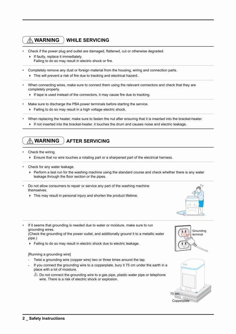
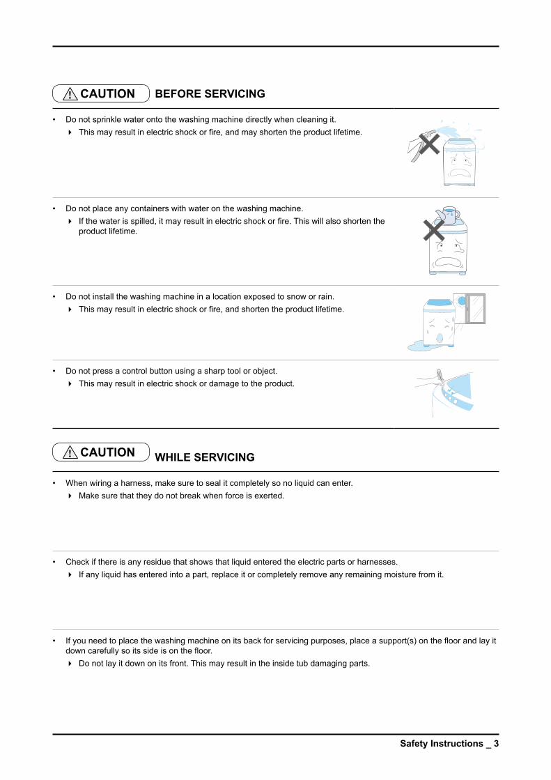
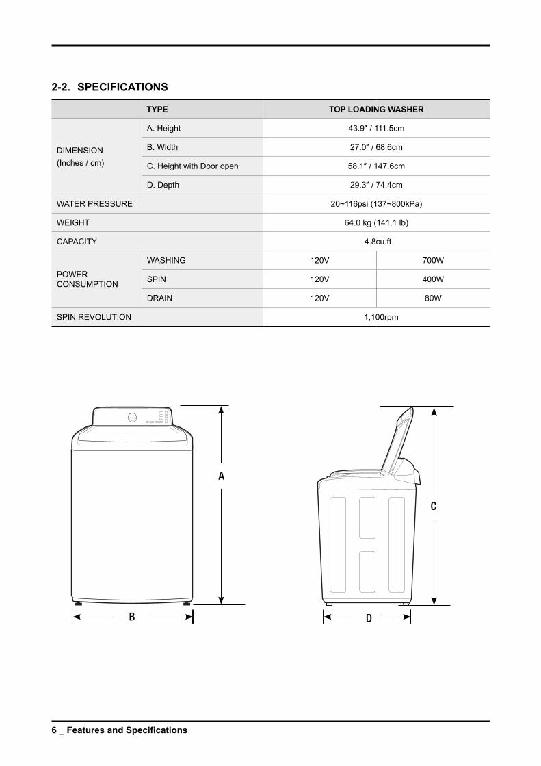
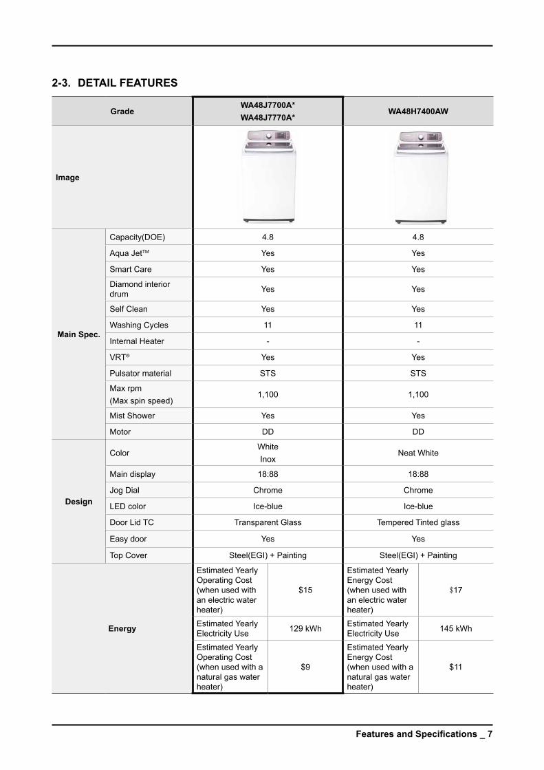
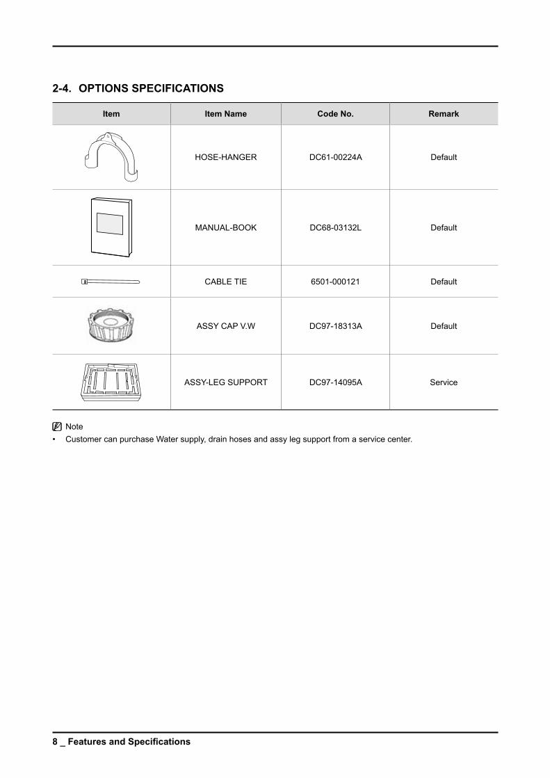
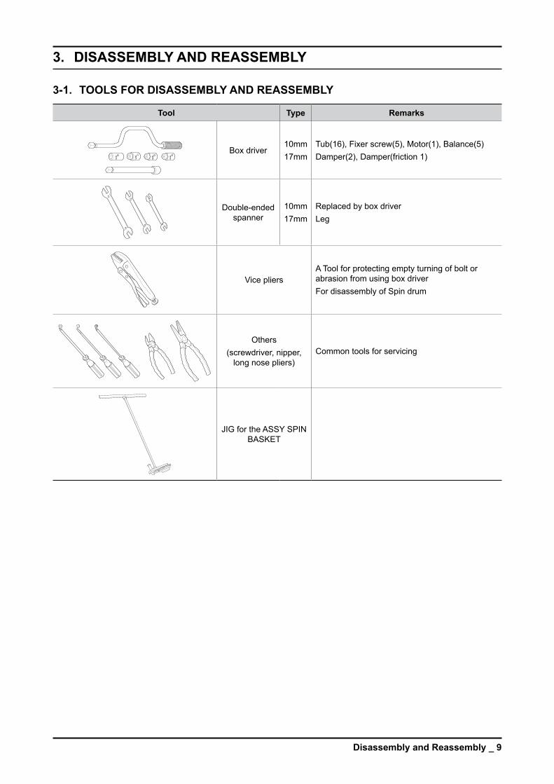
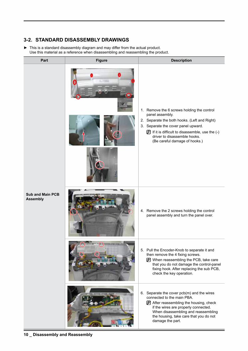
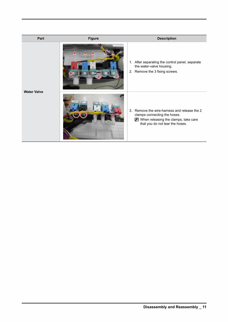
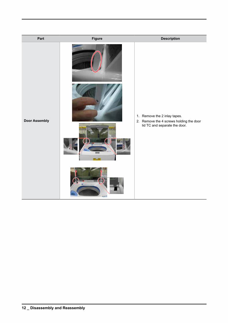
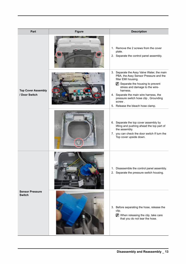
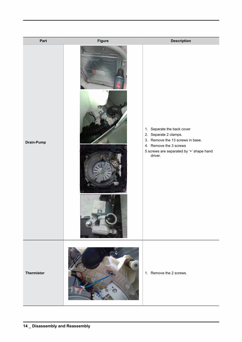
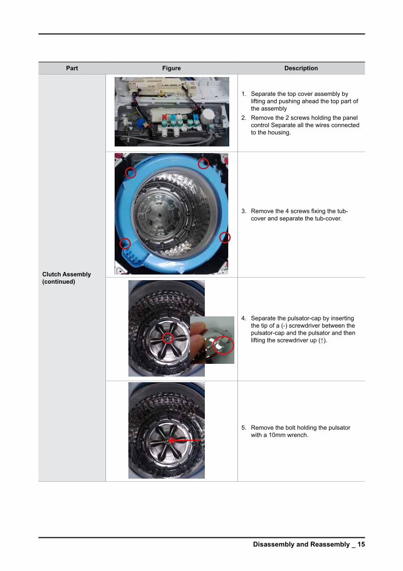
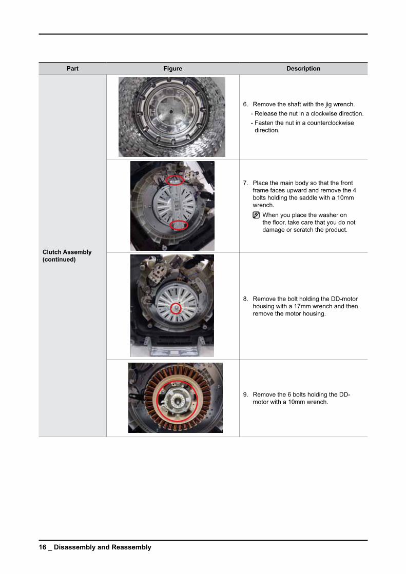
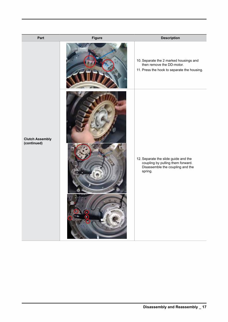
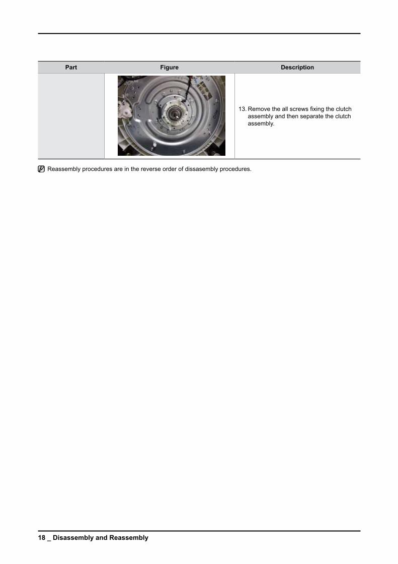
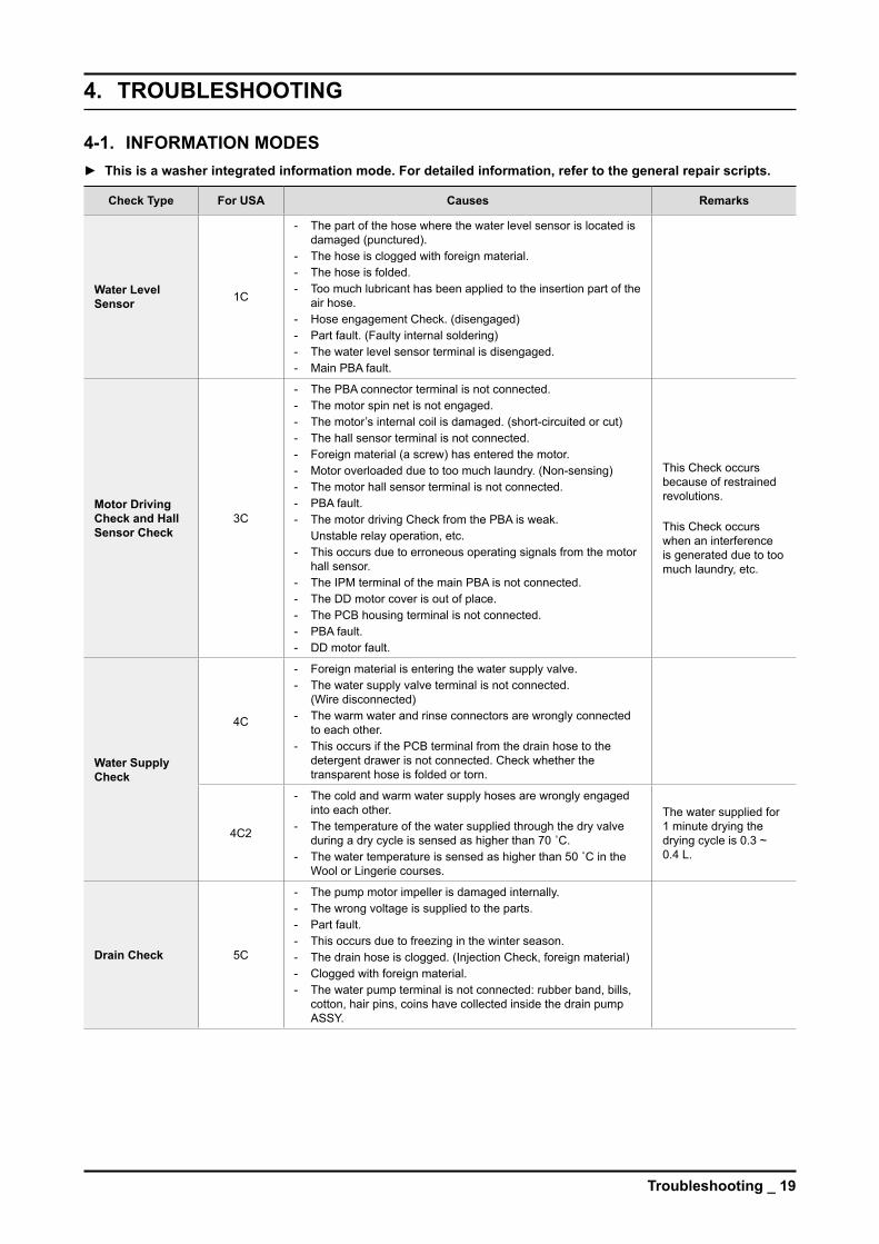
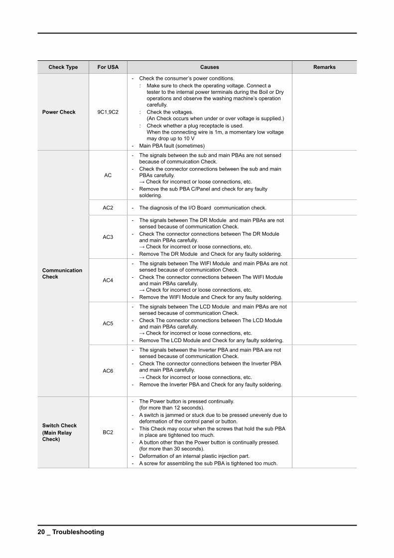
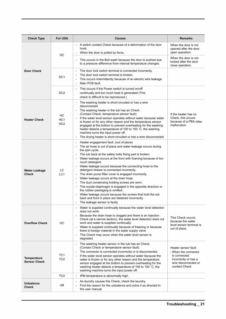
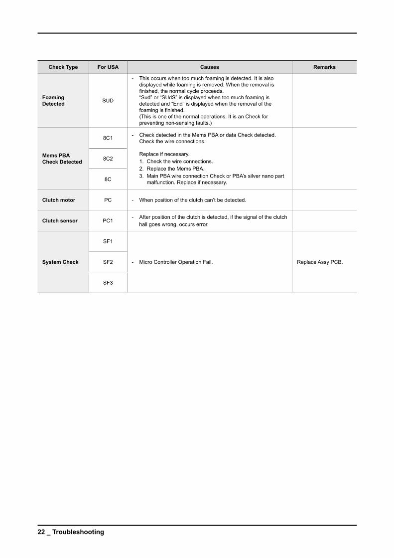
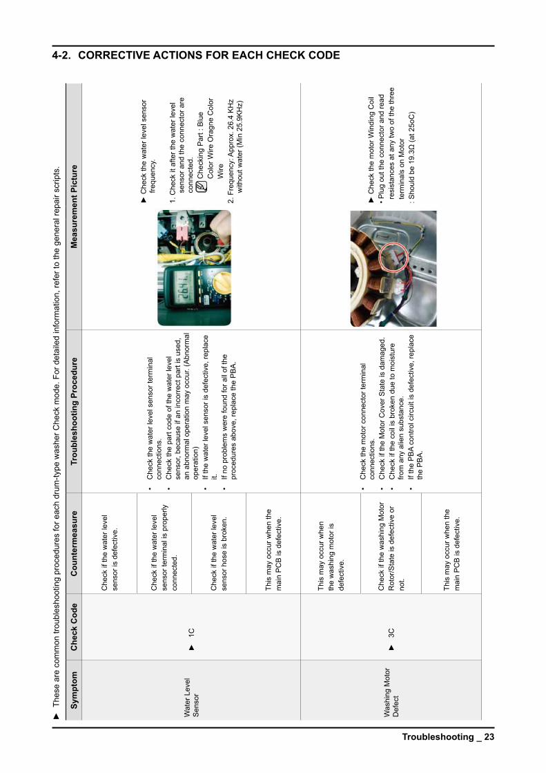
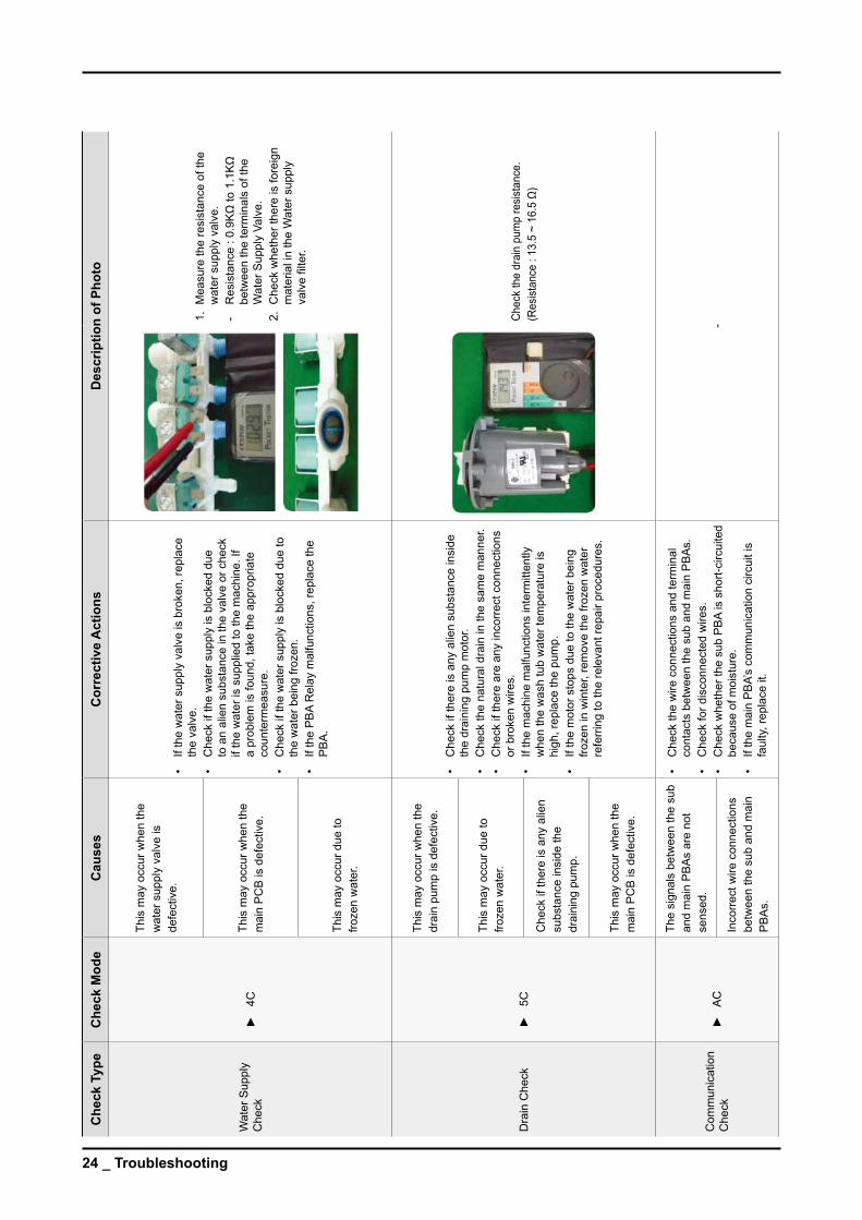
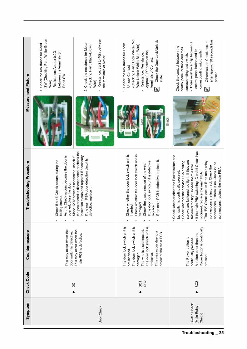
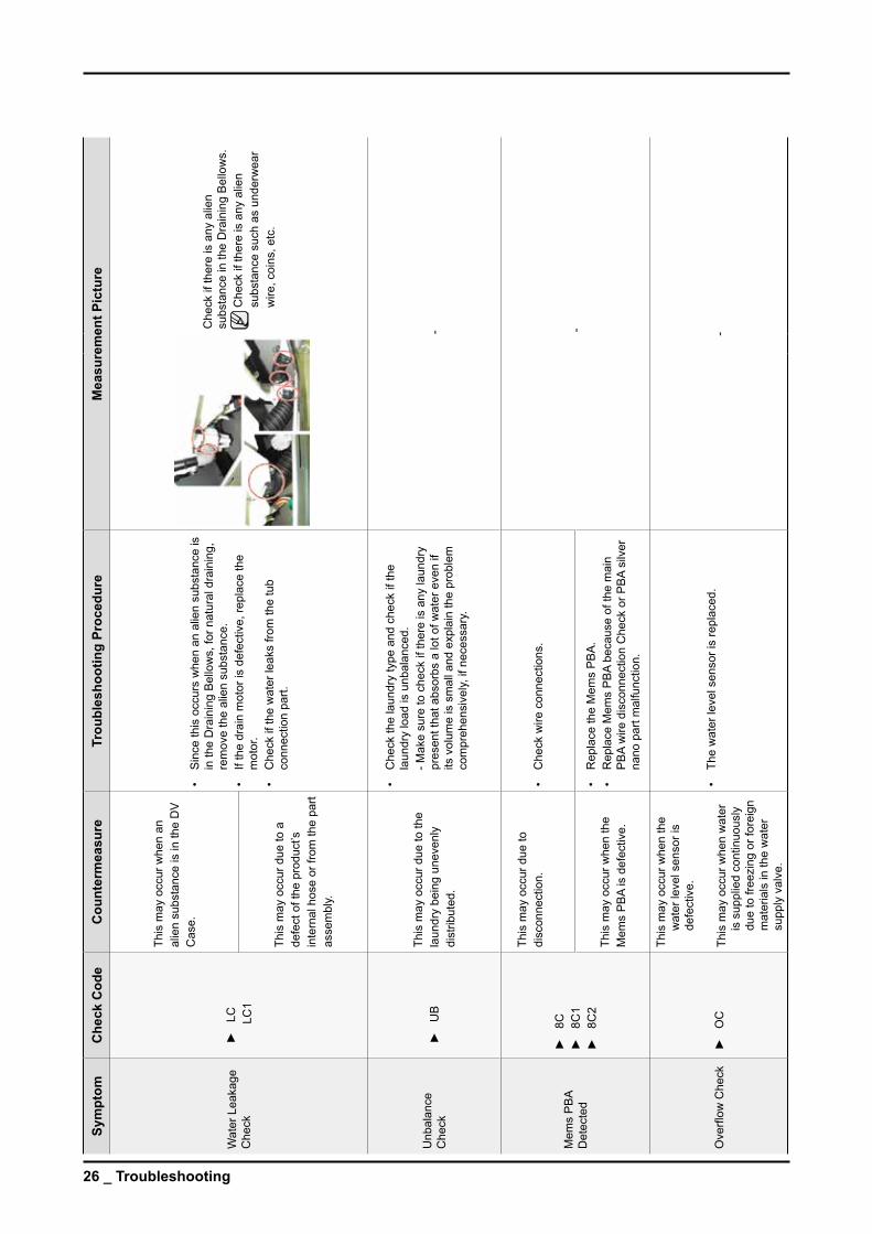
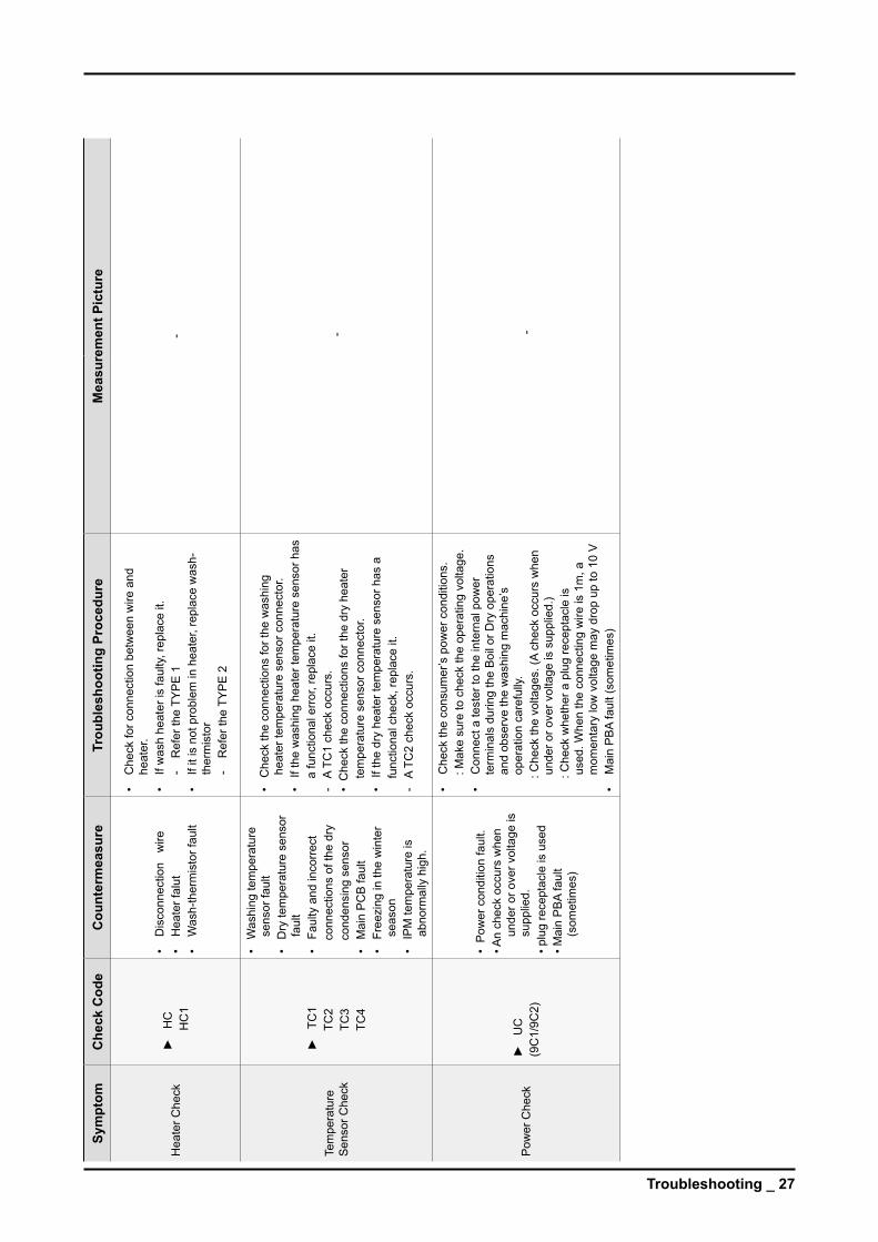
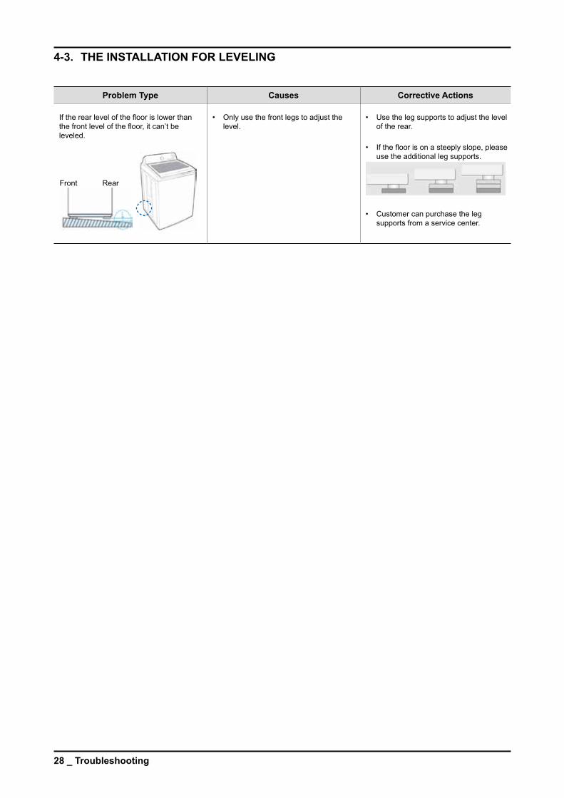
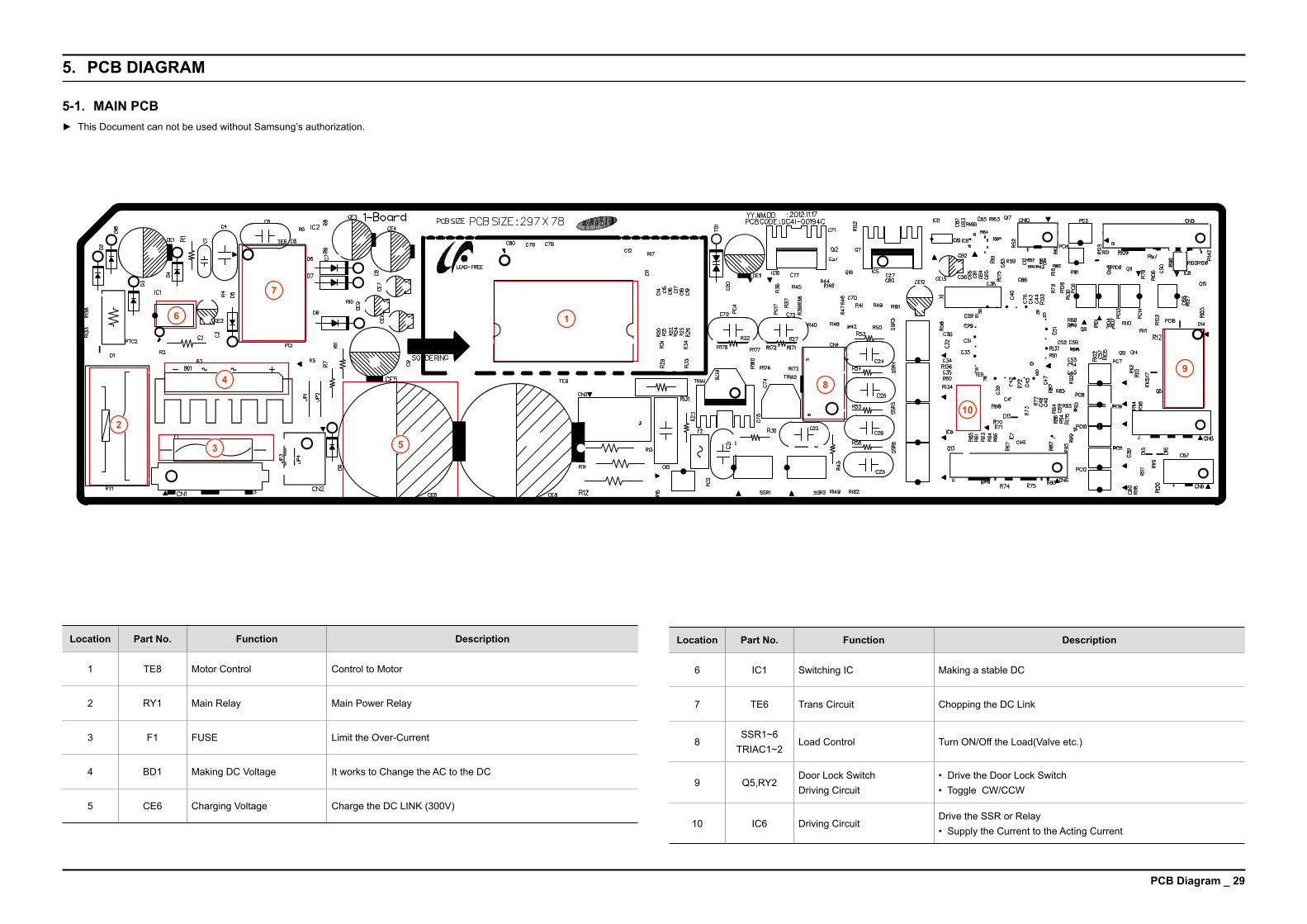
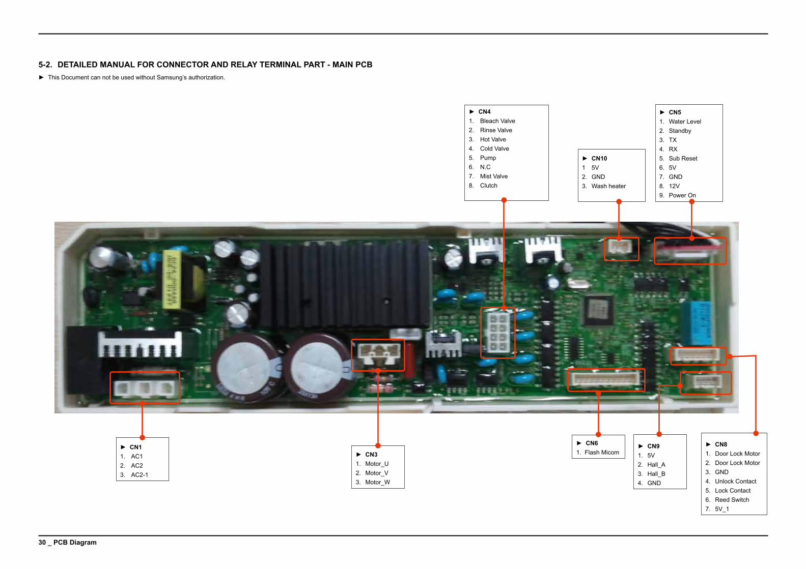
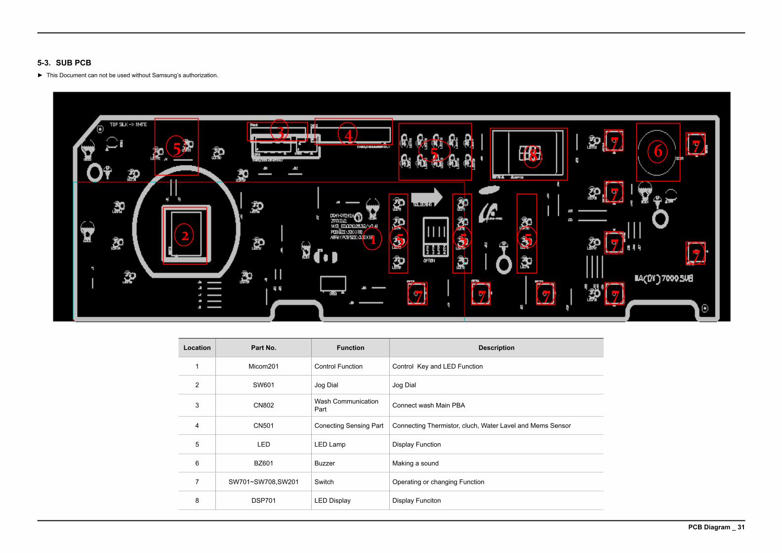
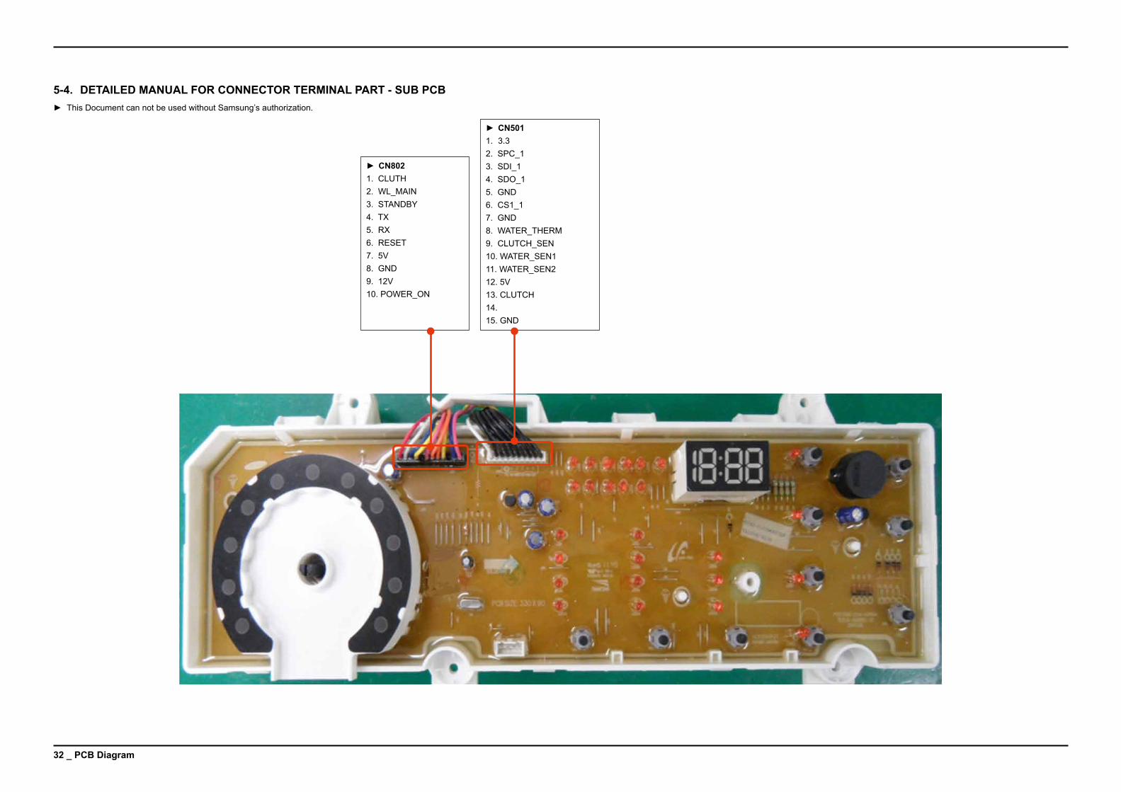
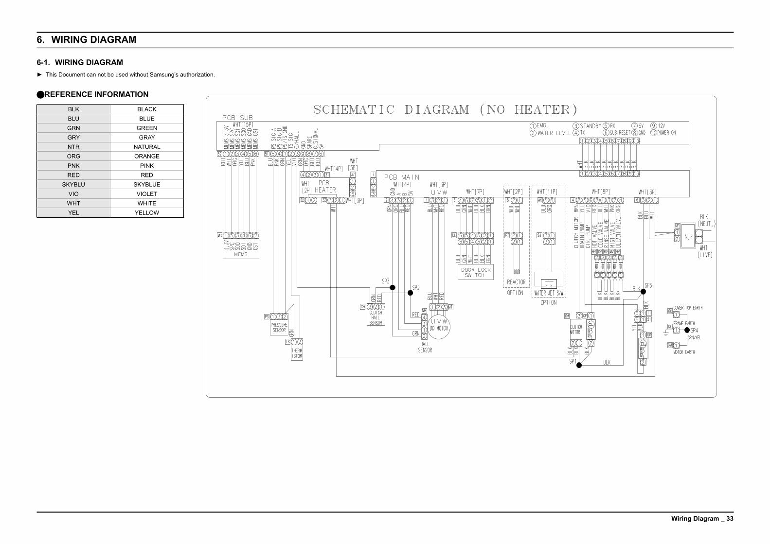
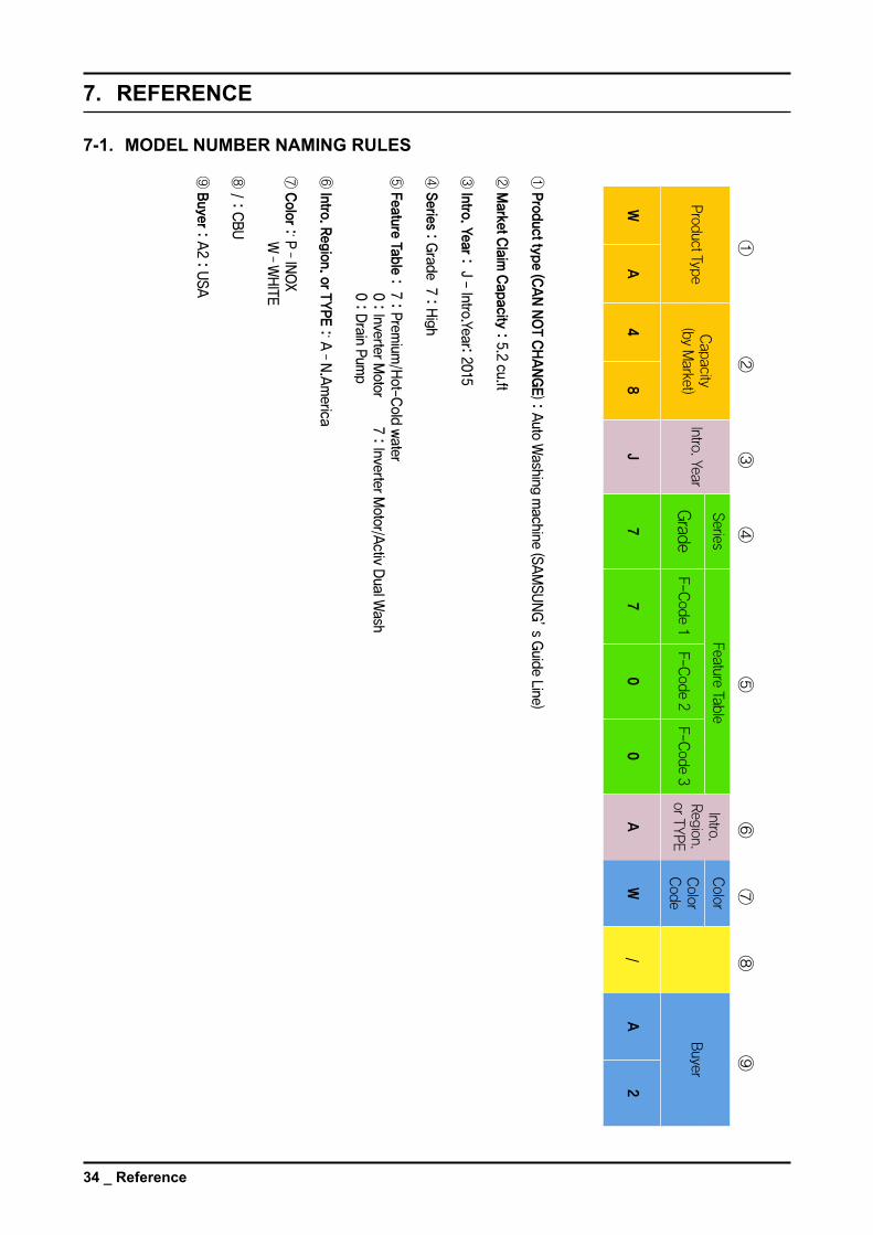
ThisServiceManualisapropertyofSamsungElectronicsCoLtdAnyunauthorizeduseofManualcanbepunishedunderapplicableInternationalandordomesticlaw
copy 2015 Samsung electronics CoLtd All rights reserved16 FEB 2015