Embed Size (px)
Citation preview
KIT# 523189-502/26/18
KS
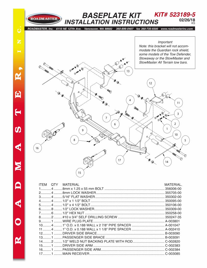
ITEM QTY MATERIAL MATERIAL.1...........4 .........8mm x 1.25 x 55 mm BOLT ................................................................ 356006-002...........4 .........8mm LOCK WASHER ......................................................................... 355705-003...........4 .........5/16” FLAT WASHER .......................................................................... 350302-004...........4 .........1/2” x 1 1/2” BOLT ............................................................................... 350095-005...........4 .........1/2” x 4 1/2” BOLT ............................................................................... 350106-006...........8 .........1/2” LOCK WASHER........................................................................... 350309-007...........6 .........1/2” HEX NUT ..................................................................................... 350258-008...........2 .........#10 x 3/4” SELF DRILLING SCREW .................................................. 350247-359...........1 .........WIRE PLUG PLATE ............................................................................ A-00380110.........4 .........1” O.D. x 0.188 WALL x 2 7/8” PIPE SPACER ................................... A-00104711 .........4 .........1” O.D. x 0.188 WALL x 1 1/8” PIPE SPACER ................................... A-00241012.........1 .........DRIVER SIDE BRACE ........................................................................ B-00309013.........1 .........PASSENGER SIDE BRACE ............................................................... B-00309114.........2 .........1/2” WELD NUT BACKING PLATE WITH ROD .................................. C-00282015.........1 .........DRIVER SIDE ARM ............................................................................ C-00238316.........1 .........PASSENGER SIDE ARM .................................................................... C-00238417.........1 .........MAIN RECEIVER ................................................................................ C-003085
1
2
3
4
5
6
7
8
910
11
12
13
14
15
16
17
ImportantNote: this bracket will not accom-modate the Guardian rock shield, some models of the Tow Defender, Stowaway or the StowMaster and StowMaster All Terrain tow bars.
R
O
A
D
M
A
S
T
E
R,
I
N
C.
ROADMASTER, Inc. 6110 NE 127th Ave. Vancouver, WA 98682 360-896-0407 fax 360-735-9300 www.roadmasterinc.com
BASEPLATE KIT INSTALLATION INSTRUCTIONS
KIT# 523189-502/26/18
KS
IMPORTANT: All baseplates must be assembled with all the bolts left loose for final adjustment and positioning (before tightening) unless otherwise instructed. All bolts must be torqued for proper strength. If more than one bolt is used per fastening point, the diagram may only show one.
• Use flat washers over all slotted holes • Use lock washers on all fasteners
• Installation of most baseplates requires moderate mechanical ap-titude and skills. We strongly recommend professional installation by an experienced installer.
• The installer must read the instructions and use all bolts and parts supplied. Failure to do so could result in loss of the towed vehicle.
• Use Loctite® Red on all bolts used for mounting this bracket.
• Every 3,000 miles, the owner must inspect the fasteners for proper torque, according to the bolt torque requirements chart on the last page of these instructions. The owner must also inspect all mount-ing points for cracks or other signs of fatigue every 3,000 miles. Failure to do so could result in loss of the towed vehicle.
• The owner must check the vehicle manufacturer's instructions for the proper procedure(s) to prepare the vehicle for towing. Some vehicles must be equipped with a transmission lube pump, an axle disconnect, driveline disconnect or free-wheeling hubs before they can be towed. Failure to properly equip the vehicle will cause severe damage to the transmission.
• If running changes were made by the vehicle manufacturer after this kit was designed, some bolts or other fasteners in the hardware pack may no longer be the correct size. It is the installer’s responsibility to verify that the baseplate is securely fastened to the vehicle and fit-ted with the correct hardware to account for these changes. Failure to securely fasten the baseplate could result in loss of the towed vehicle.
• If the towed vehicle has been in an accident, it must be properly re-paired before attaching the baseplate. Do not install the baseplate if any structural frame damage is found. Failure to repair the damage could result in the loss of the towed vehicle.
ROADMASTER Limited Warranty, including One-Year Conditional Warranty Text and Product Registration Card, in Carton.
• Roadmaster manufactures many styles of baseplates. If your base-plate has removable arms, they must be removed before driving the vehicle, unless the arms can be pinned or padlocked in place. If not secured, the arms could vibrate out, resulting in non-warranty damage or personal injury.
• Some motorhome chassis have such a tight turning radius that you can damage your motorhome, towed vehicle, tow bar or baseplate while turn-ing sharply. Before getting on the road, test your turning radius in an empty parking lot. Turning too sharply could result in non-warranty damage to towing system, motorhome and/or towed vehicle.
• Do not back up with the towed vehicle attached or non-warranty damage will occur to your towing system, motorhome and/or towed vehicle.
• The safety cables must connect the towing vehicle to the towed vehicle frame to frame, with the cables crossed, with enough slack for sharp turns. Refer to the cable instructions for proper routing. Failure to leave enough slack in the safety cables, or failure to connect the safety cables frame to frame, will result in the loss of the towed vehicle.
• This kit is designed for use with ROADMASTER tow bars and ROAD-MASTER adaptors only. Using this kit with other brands, without an approved ROADMASTER adaptor, may result in non-warranty damage or injury.
• Do not use this document for custom fabrication, as it may not show all parts or structural components. Custom fabrication, or any attempt to copy this baseplate design, could result in loss of the towed vehicle.
• Upon final installation, the installer must inspect the baseplate to ensure adequate clearance, particularly around hoses, air condi-tioner lines, radiators, etc., or non-warranty damage to the towed vehicle will result.
• This baseplate is only warranteed for the original installation. In-stalling a used baseplate on another vehicle is not recommended and will void the warranty.
Failure to follow these instructions can result in property damage, personal injury or even death.WARNING
BASEPLATE KIT INSTALLATION INSTRUCTIONS
ROADMASTER, Inc. 6110 NE 127th Ave. Vancouver, WA 98682 360-896-0407 fax 360-735-9300 www.roadmasterinc.com
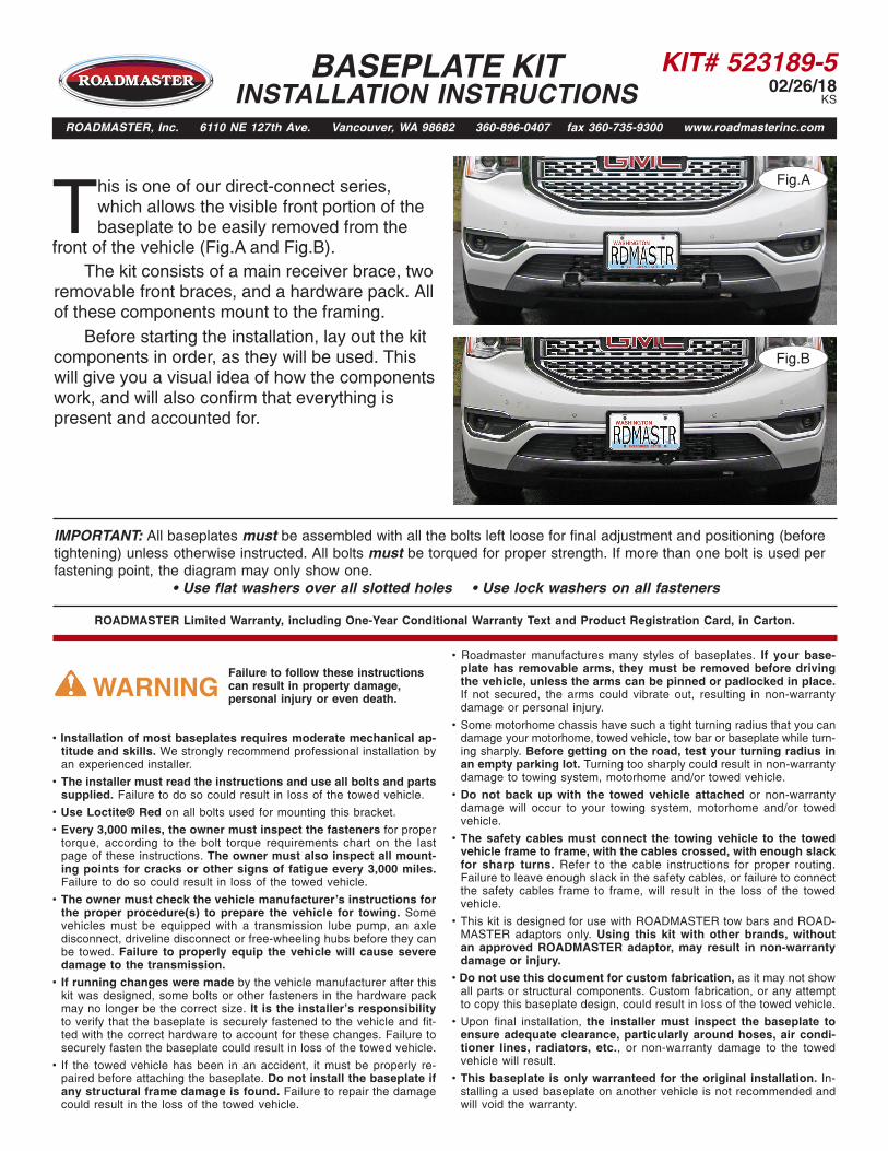
Fig.B
This is one of our direct-connect series, which allows the visible front portion of the baseplate to be easily removed from the
front of the vehicle (Fig.A and Fig.B). The kit consists of a main receiver brace, two removable front braces, and a hardware pack. All of these components mount to the framing. Before starting the installation, lay out the kit components in order, as they will be used. This will give you a visual idea of how the components work, and will also confirm that everything is present and accounted for.
Fig.A
KIT# 523189-502/26/18
KS
BASEPLATE KIT INSTALLATION INSTRUCTIONS
ROADMASTER, Inc. 6110 NE 127th Ave. Vancouver, WA 98682 360-896-0407 fax 360-735-9300 www.roadmasterinc.com
All illustrations and specifications contained herein are based on the latest information available at the time of publication approval. ROADMASTER, INC. reserves the right to make changes at any time without notice in material, specification and models or to discontinue models.
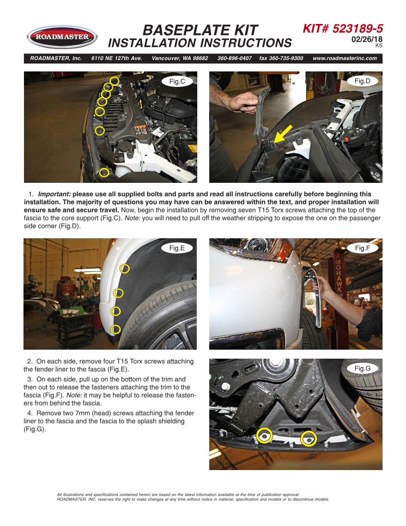
1. Important: please use all supplied bolts and parts and read all instructions carefully before beginning this installation. The majority of questions you may have can be answered within the text, and proper installation will ensure safe and secure travel. Now, begin the installation by removing seven T15 Torx screws attaching the top of the fascia to the core support (Fig.C). Note: you will need to pull off the weather stripping to expose the one on the passenger side corner (Fig.D).
2. On each side, remove four T15 Torx screws attaching the fender liner to the fascia (Fig.E).
3. On each side, pull up on the bottom of the trim and then out to release the fasteners attaching the trim to the fascia (Fig.F). Note: it may be helpful to release the fasten-ers from behind the fascia.
4. Remove two 7mm (head) screws attaching the fender liner to the fascia and the fascia to the splash shielding (Fig.G).
Fig.C Fig.D
Fig.E
Fig.G
Fig.F
KIT# 523189-502/26/18
KS
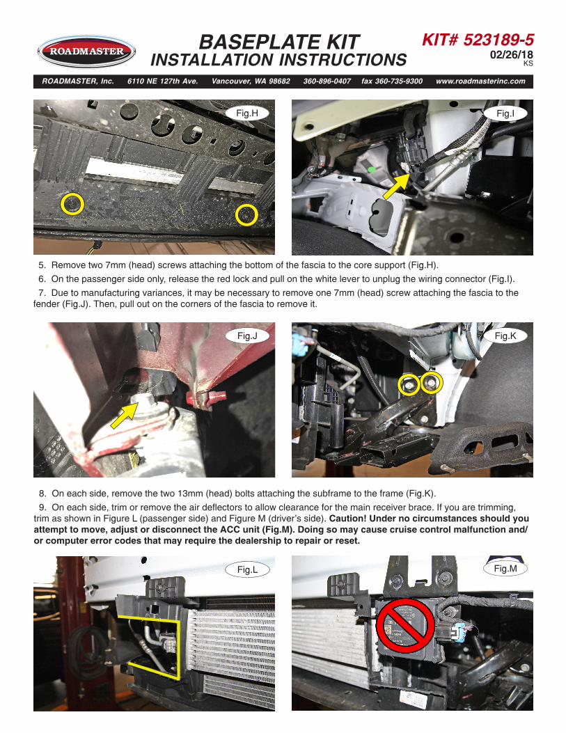
5. Remove two 7mm (head) screws attaching the bottom of the fascia to the core support (Fig.H).
6. On the passenger side only, release the red lock and pull on the white lever to unplug the wiring connector (Fig.I).
7. Due to manufacturing variances, it may be necessary to remove one 7mm (head) screw attaching the fascia to the fender (Fig.J). Then, pull out on the corners of the fascia to remove it.
BASEPLATE KIT INSTALLATION INSTRUCTIONS
ROADMASTER, Inc. 6110 NE 127th Ave. Vancouver, WA 98682 360-896-0407 fax 360-735-9300 www.roadmasterinc.com
Fig.J
Fig.RFig.L
Fig.K
8. On each side, remove the two 13mm (head) bolts attaching the subframe to the frame (Fig.K).
9. On each side, trim or remove the air deflectors to allow clearance for the main receiver brace. If you are trimming, trim as shown in Figure L (passenger side) and Figure M (driver's side). Caution! Under no circumstances should you attempt to move, adjust or disconnect the ACC unit (Fig.M). Doing so may cause cruise control malfunction and/or computer error codes that may require the dealership to repair or reset.
Fig.RFig.M
Fig.H Fig.I
KIT# 523189-502/26/18
KS
BASEPLATE KIT INSTALLATION INSTRUCTIONS
ROADMASTER, Inc. 6110 NE 127th Ave. Vancouver, WA 98682 360-896-0407 fax 360-735-9300 www.roadmasterinc.com
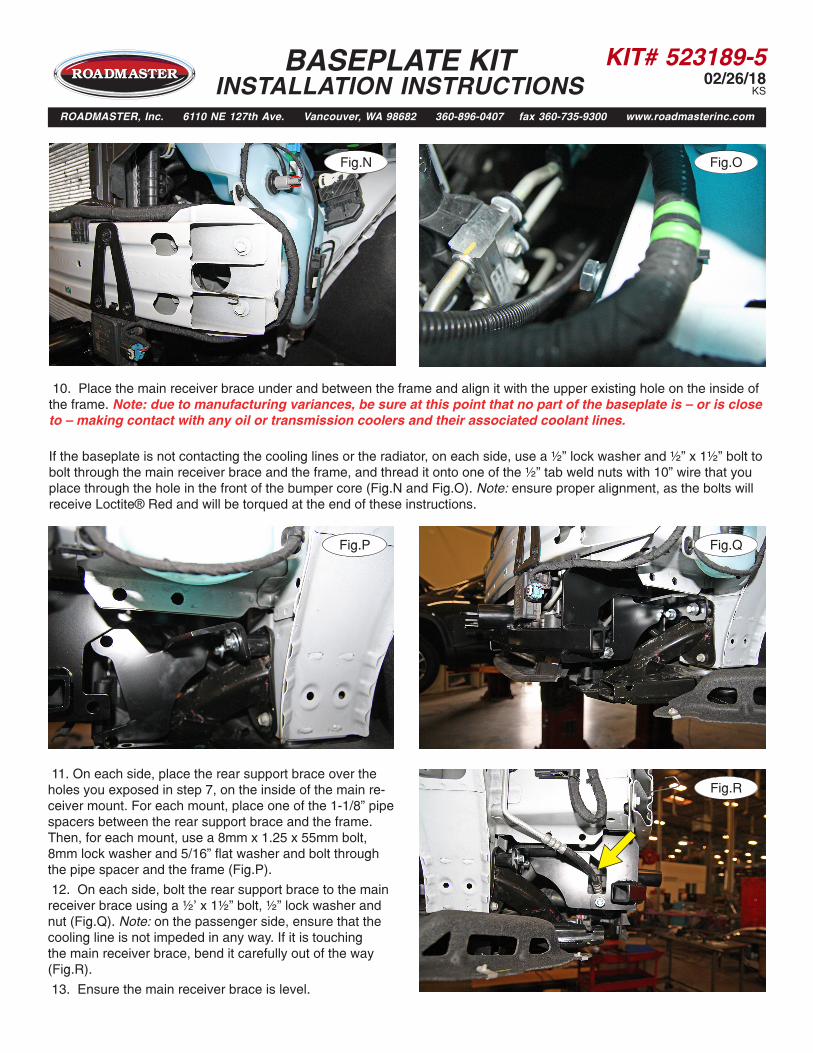
10. Place the main receiver brace under and between the frame and align it with the upper existing hole on the inside of the frame. Note: due to manufacturing variances, be sure at this point that no part of the baseplate is — or is close to — making contact with any oil or transmission coolers and their associated coolant lines.
If the baseplate is not contacting the cooling lines or the radiator, on each side, use a ½” lock washer and ½” x 1½” bolt to bolt through the main receiver brace and the frame, and thread it onto one of the ½” tab weld nuts with 10” wire that you place through the hole in the front of the bumper core (Fig.N and Fig.O). Note: ensure proper alignment, as the bolts will receive Loctite® Red and will be torqued at the end of these instructions.
11. On each side, place the rear support brace over the holes you exposed in step 7, on the inside of the main re-ceiver mount. For each mount, place one of the 1-1/8” pipe spacers between the rear support brace and the frame. Then, for each mount, use a 8mm x 1.25 x 55mm bolt, 8mm lock washer and 5/16” flat washer and bolt through the pipe spacer and the frame (Fig.P).
12. On each side, bolt the rear support brace to the main receiver brace using a ½’ x 1½” bolt, ½” lock washer and nut (Fig.Q). Note: on the passenger side, ensure that the cooling line is not impeded in any way. If it is touching the main receiver brace, bend it carefully out of the way (Fig.R).
13. Ensure the main receiver brace is level.
Fig.RFig.N Fig.RFig.O
Fig.RFig.P Fig.RFig.Q
Fig.RFig.R
KIT# 523189-502/26/18
KS
BASEPLATE KIT INSTALLATION INSTRUCTIONS
ROADMASTER, Inc. 6110 NE 127th Ave. Vancouver, WA 98682 360-896-0407 fax 360-735-9300 www.roadmasterinc.com
Fig.RFig.S
Fig.RFig.U Fig.RFig.V
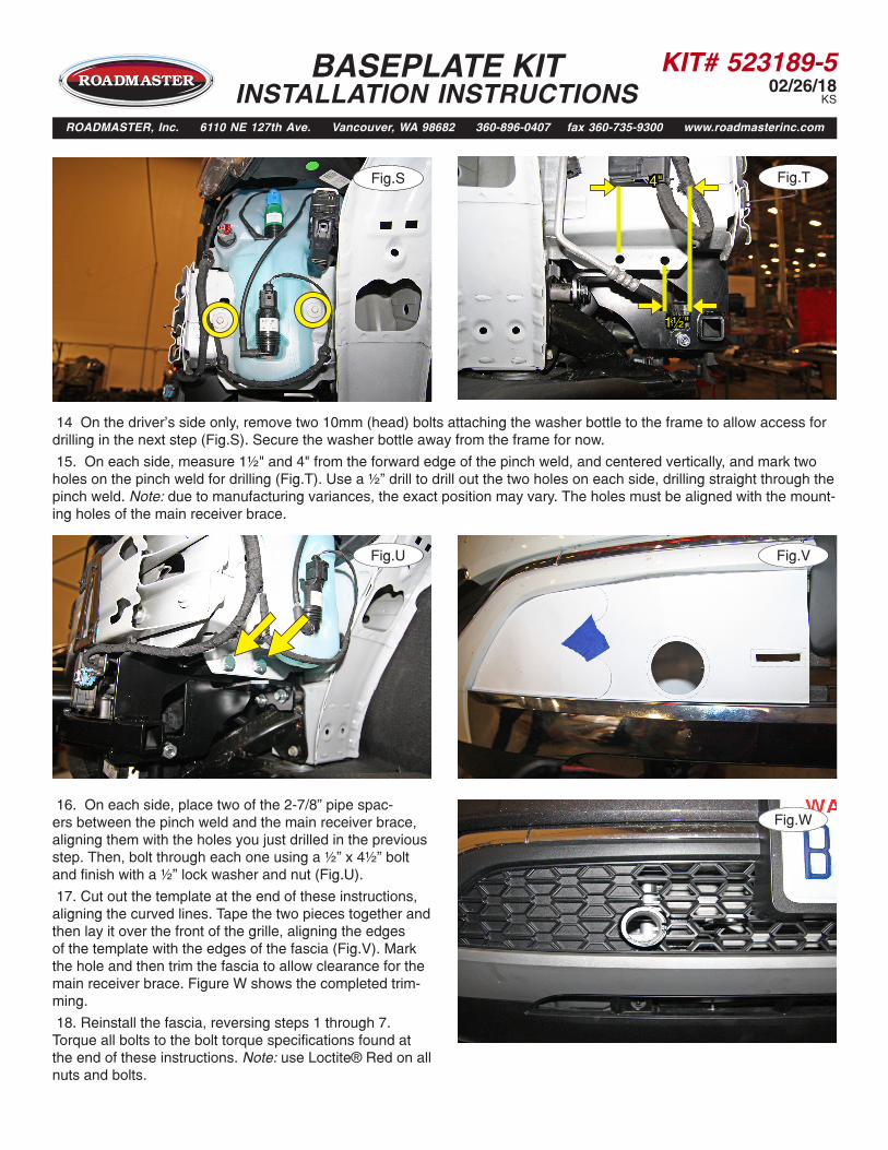
14 On the driver’s side only, remove two 10mm (head) bolts attaching the washer bottle to the frame to allow access for drilling in the next step (Fig.S). Secure the washer bottle away from the frame for now.
15. On each side, measure 1½" and 4" from the forward edge of the pinch weld, and centered vertically, and mark two holes on the pinch weld for drilling (Fig.T). Use a ½” drill to drill out the two holes on each side, drilling straight through the pinch weld. Note: due to manufacturing variances, the exact position may vary. The holes must be aligned with the mount-ing holes of the main receiver brace.
16. On each side, place two of the 2-7/8” pipe spac-ers between the pinch weld and the main receiver brace, aligning them with the holes you just drilled in the previous step. Then, bolt through each one using a ½” x 4½” bolt and finish with a ½” lock washer and nut (Fig.U).
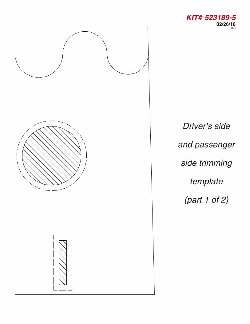
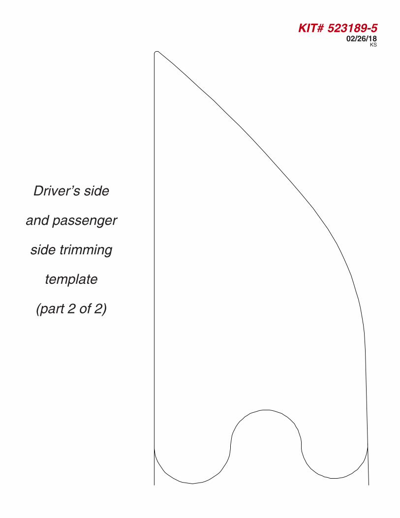
17. Cut out the template at the end of these instructions, aligning the curved lines. Tape the two pieces together and then lay it over the front of the grille, aligning the edges of the template with the edges of the fascia (Fig.V). Mark the hole and then trim the fascia to allow clearance for the main receiver brace. Figure W shows the completed trim-ming.
18. Reinstall the fascia, reversing steps 1 through 7. Torque all bolts to the bolt torque specifications found at the end of these instructions. Note: use Loctite® Red on all nuts and bolts.
Fig.RFig.W
Fig.RFig.T4"
1½"
KIT# 523189-502/26/18
KS
BASEPLATE KIT INSTALLATION INSTRUCTIONS
ROADMASTER, Inc. 6110 NE 127th Ave. Vancouver, WA 98682 360-896-0407 fax 360-735-9300 www.roadmasterinc.com
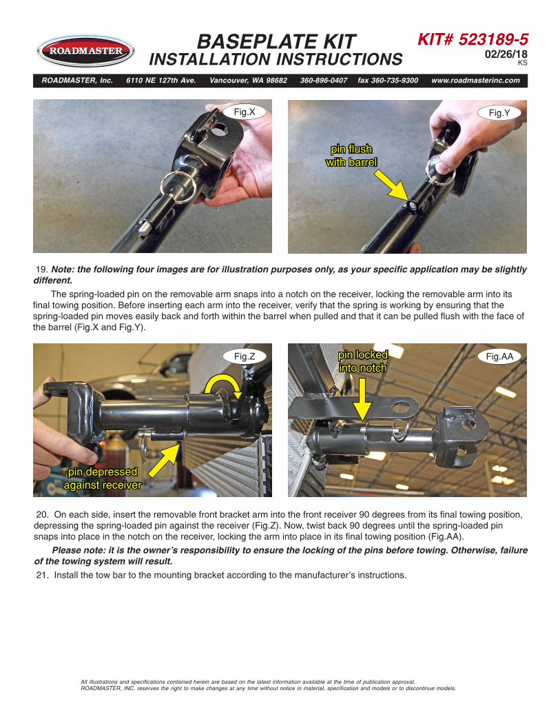
19. Note: the following four images are for illustration purposes only, as your specific application may be slightly different.
The spring-loaded pin on the removable arm snaps into a notch on the receiver, locking the removable arm into its final towing position. Before inserting each arm into the receiver, verify that the spring is working by ensuring that the spring-loaded pin moves easily back and forth within the barrel when pulled and that it can be pulled flush with the face of the barrel (Fig.X and Fig.Y).
20. On each side, insert the removable front bracket arm into the front receiver 90 degrees from its final towing position, depressing the spring-loaded pin against the receiver (Fig.Z). Now, twist back 90 degrees until the spring-loaded pin snaps into place in the notch on the receiver, locking the arm into place in its final towing position (Fig.AA).
Please note: it is the owner's responsibility to ensure the locking of the pins before towing. Otherwise, failure of the towing system will result.
21. Install the tow bar to the mounting bracket according to the manufacturer's instructions.
All illustrations and specifications contained herein are based on the latest information available at the time of publication approval. ROADMASTER, INC. reserves the right to make changes at any time without notice in material, specification and models or to discontinue models.
Fig.RFig.X Fig.RFig.Y
pin flush with barrel
Fig.RFig.Z Fig.RFig.AA
pin depressedagainst receiver
pin lockedinto notch
KIT# 523189-502/26/18
KS
BOLT TORQUE REQUIREMENTS
METRIC BOLTSThread Size Grade Plated / Unplated12mm-1.25 ........8.8 ............70 ft./lb. 65 ft./lb. 12mm-1.5 ..........8.8 ............66 ft./lb. 61 ft./lb.12mm-1.75 ........8.8 ...........65 ft./lb. 60 ft./lb.14mm-2.0 ..........8.8 .........104 ft./lb. 97 ft./lb.
METRIC BOLTSThread Size Grade Plated / Unplated 8mm-1.0 ............8.8 ............20 ft./lb. 18 ft./lb. 8mm-1.25 .........8.8 ............19 ft./lb. 18 ft./lb.10mm-1.25 ........8.8 ...........38 ft./lb. 36 ft./lb.10mm-1.5 ..........8.8 ...........37 ft./lb. 35 ft./lb.
STANDARD BOLTSThread Size Grade Torque3/8....................... 5 ........................... 13 ft./lb. 3/8....................... 5 ........................... 23 ft./lb.7/16..................... 5 ........................... 37 ft./lb.1/2....................... 5 ........................... 56 ft./lb.5/8....................... 5 ......................... 150 ft./lb.
Note: The torque values represented below are intended as general guidelines. Torque requirements for specific applications may vary. Roadmaster does not warrant this information to be accurate for all applications and disclaims all liability for any claims or damages which may result from its use.
All illustrations and specifications contained herein are based on the latest information available at the time of publication approval. ROADMASTER, INC. reserves the right to make changes at any time without notice in material, specification and models or to discontinue models.
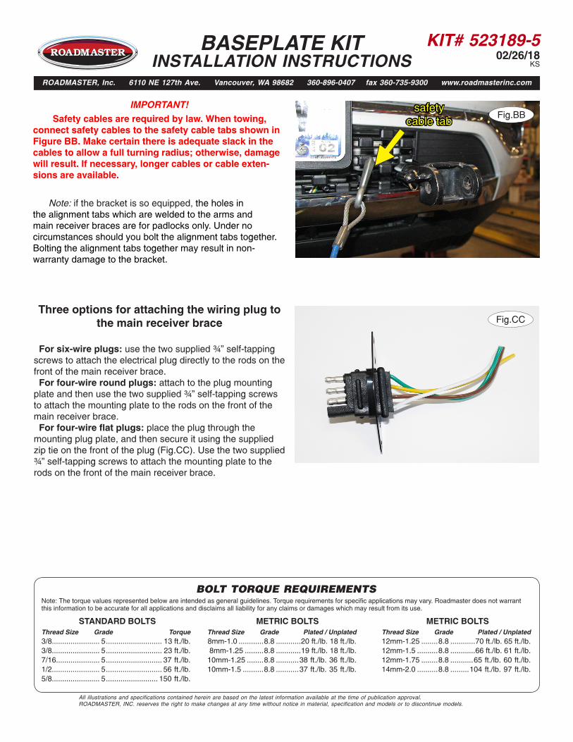
IMPORTANT!
Safety cables are required by law. When towing, connect safety cables to the safety cable tabs shown in Figure BB. Make certain there is adequate slack in the cables to allow a full turning radius; otherwise, damage will result. If necessary, longer cables or cable exten-sions are available.
Note: if the bracket is so equipped, the holes in the alignment tabs which are welded to the arms and main receiver braces are for padlocks only. Under no circumstances should you bolt the alignment tabs together. Bolting the alignment tabs together may result in non-warranty damage to the bracket.
BASEPLATE KIT INSTALLATION INSTRUCTIONS
ROADMASTER, Inc. 6110 NE 127th Ave. Vancouver, WA 98682 360-896-0407 fax 360-735-9300 www.roadmasterinc.com
Fig.CCThree options for attaching the wiring plug to
the main receiver brace For six-wire plugs: use the two supplied ¾” self-tapping screws to attach the electrical plug directly to the rods on the front of the main receiver brace. For four-wire round plugs: attach to the plug mounting plate and then use the two supplied ¾” self-tapping screws to attach the mounting plate to the rods on the front of the main receiver brace. For four-wire flat plugs: place the plug through the mounting plug plate, and then secure it using the supplied zip tie on the front of the plug (Fig.CC). Use the two supplied ¾” self-tapping screws to attach the mounting plate to the rods on the front of the main receiver brace.
Fig.BBsafety
cable tab
KIT# 523189-502/26/18
KS
Driver's side
and passenger
side trimming
template
(part 1 of 2)

KIT# 523189-502/26/18
KSthis page is intentionally blank to allow for template printing
KIT# 523189-502/26/18
KS
Driver's side
and passenger
side trimming
template
(part 2 of 2)