Embed Size (px)
DESCRIPTION
Barrier Free Built Environment
Citation preview
DESIGN MANUAL
FOR A BARRIER- FREE
BUILT ENVIRONMENT
DESIGN MANUAL
FOR A BARRIER- FREE
BUILT ENVIRONMENT
December 2004
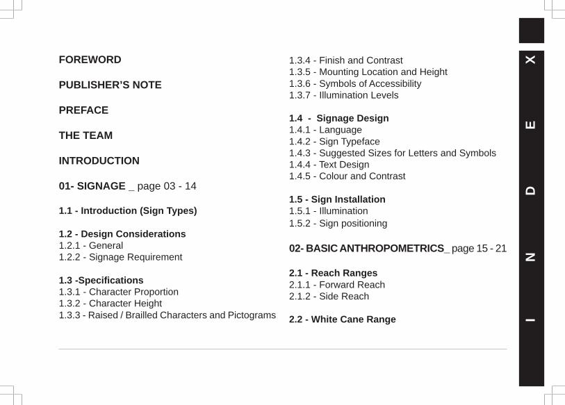
FOREWORD
PUBLISHER’S NOTE
PREFACE
THE TEAM
INTRODUCTION
01- SIGNAGE _ page 03 - 14
1.1 - Introduction (Sign Types)
1.2 - Design Considerations1.2.1 - General1.2.2 - Signage Requirement
1.3 -Specifications1.3.1 - Character Proportion1.3.2 - Character Height1.3.3 - Raised / Brailled Characters and Pictograms I
N
D
E
X1.3.4 - Finish and Contrast
1.3.5 - Mounting Location and Height1.3.6 - Symbols of Accessibility1.3.7 - Illumination Levels
1.4 - Signage Design1.4.1 - Language1.4.2 - Sign Typeface1.4.3 - Suggested Sizes for Letters and Symbols1.4.4 - Text Design1.4.5 - Colour and Contrast
1.5 - Sign Installation1.5.1 - Illumination1.5.2 - Sign positioning
02- BASIC ANTHROPOMETRICS_ page 15 - 21
2.1 - Reach Ranges2.1.1 - Forward Reach2.1.2 - Side Reach
2.2 - White Cane Range
I
N
D
E
X2.3 - Common Reach Zone
2.4. - Circulation Dimensions2.4.1 - Wheelchair Dimensions2.4.2 - Walkway Width for Crutch Users
2.5 -Vision Cone
2.6 - Heights of People
2.7 - Lighting
03- SPACE ALLOWANCES _ page 22 - 26
3.1 - Minimum Access Provisions
3.2 - General Allowances3.2.1 - Wheelchair Passage Width3.2.2 - Width for Wheelchair Passing3.2.3 - Wheelchair Turning Space
3.3 - Clear Floor or Ground Space for Wheelchairs
04- ACCESSIBLE ROUTES _ page 27 - 50
4.1 - Physical Parameters4.1.1- Location4.1.2 - Width4.1.3 - Passing Space4.1.4 - Head Room4.1.5 - Slope4.1.6 - Changes in Levels4.1.7- Guiding Blocks4.1.8 - Signage
4.2 - Protruding Objects
4.3 - Ground and Floor Surfaces4.3.1 - Surface Textures4.3.2 - Levels4.3.3 - Carpets4.3.4 - Gratings4.3.5 - Guiding Blocks (Detectable Warnings)4.3.5.1 - Walking Surfaces4.3.5.2 - Vehicular Areas4.3.5.3 - Reflecting Pools
I
N
D
E
X4.4 - Vehicular -Parking and Passenger Loading Zones
4.4.1- Location4.4.2 - Parking Spaces4.4.3 - Passenger Loading Zones
4.5 - Curb Ramps4.5.1 - Location4.5.2 - Width4.5.3 - Slope
4.6 - Ramps4.6.1 - Slope and Rise4.6.2 - Landings4.6.3 - Clear Width4.6.4 - Handrails
4.7 - Stairs4.7.1 - Treads and Risers4.7.2 - Nosing4.7.3 - Handrails
4.8 - Elevators4.8.1 - General4.8.2 - Automatic Operation4.8.3 - Hall Call Buttons4.8.4 - Car Controls4.8.5 - Audio & Visual Signals4.8.6 - Raised and Braille Characters
on the Hoist- Way Entrances4.8.7 - Door Delay for Car Calls4.8.8 - Specifications for Car
Dimensions4.8.9 - Floor and Wall Specifications
for the Car4.8.10 - Illumination Levels
4.9 - Platform Lifts / Wheelchair Lifts4.9.1- Lift Size4.9.2 - Vertical Movement Platform Lifts4.9.3 - Inclined Movement Platform Lifts
4.10 - Handrail Requirements4.10.1 - Handrail Form4.10.2 - Handrail Placement4.10.3 - Handrail Texture
05- ENTRANCES _ page 51
5.1 - Mandatory
5.2 - Suggestive
06- DOORS _ page 52 - 58
6.1 - Door Clearances
6.2 - Door Hardware
6.3 - Suggestive
07- WINDOWS _ page 59
08- WASH / BATHROOMAND SHOWER AREA _ page 60 - 72
8.1 - Toilet Cubicle
8.2 - Water Closets
8.3 - Bathtubs
8.4 - Washbasins
8.5 - Urinals
8.6 - Washroom Accessories
09- DRINKING WATER FOUNTAINS _ page 72
10- KITCHENS _ page 73 -75
10.1- Mandatory
10.2 - Suggestive
I
N
D
E
X
I
N
D
E
X
10.3 - Service Counters
11- STORAGE _ page 76 - 77
11.1 - Clear Floor Space
11.2 - Height
12- TELEPHONES _ page 78 - 80
12.1 -Clear Floor or Ground Space
12.2 - Controls
12.3 - Mounting Heights
12.4 - Protruding Objects
12.5 - Hearing Aid Compatible and Volume Control Telephones
12.6 -Telephone Books
12.7 - Cord Length
12.8 - Text Telephones
13- FIXED OR BUILT-IN FURNITURE (SEATING, BENCHES, TABLES)_ page 81
14- AUTOMATED TELLERMACHINES _ page 83 - 84
14.1- Clear Floor Space
14.2- Reach Ranges14.2.1 -Forward Approach Only14.2.2 -Parallel Approach Only
14.3 - Controls
14.4- Equipments for Persons with Vision Impairments
14.5 - Exceptions
15 - ALARMS _ page 85 - 86
15.1- Location
15.2- Audible Alarms15.3 -Visual Alarms
15.4- Auxiliary Alarms
16- GENERAL CONTROLS ANDOPERATING MECHANISMS_ page 87 - 88
16.1 - Clear Floor Space
16.2 - Height
16.3 - Operation
16.4 - Exceptions
REFERENCES _ page 89
I
N
D
E
XABOUT THE ORGANISATIONS_ page 90 - 92
CONTACT DETAILS _ page 93
APPENDIX _ page 94 - 100
PARTNERS IN ACCESSIBILITY MOVEMENT _ page 101
FO
RE
WO
RDFOREWORD
Disability is not a phenomenon but is a phase.Everyone at one point or the other passesthrough such phases. The elderly, ill, pregnant,obese, children, persons with fracture or withluggage could all be described as passingthrough a phase of disability. Even during suchphases each one has the right to live in dignity.Accessibility, therefore, cannot be an aspect ofsympathy but is very much the right of everyindividual. Barrier-free design, therefore, is aprofessional obligation as well as a societalcommitment of design professionals.
Though unintended, most of our buildings todayremain inaccessible to many. This is largely due tothe lack of conscious efforts, concerns for thedisabled and lack of basic information on whatconstitutes an accessible design. A universaldesign, not remaining synonymous only with theprovision of ramps, involves many more aspects
to consider. This neither implies an additionaldemand nor involves an extra cost, if integratedright from the conception of the design. With thispremise it is imperative to compile a comprehensivereference document that stipulates necessaryprovisions for universal designs – especially thespace design. While numerous references areavailable, they tend to be disparate and not entirelycompatible with Indian conditions.
I am glad that with sincere efforts from NGOsand architects, this detailed comprehensive andindigenous manual for a barrier-free builtenvironment is realised. This should prove to bean authentic reference document. A must forarchitects, interior designers and space planners.To be kept alongside the measuring scale.
Balkrishna DoshiArchitect-Planner
FO
RE
WO
RDFOREWORD
It is my pleasure to endorse this referencemanual for designers to make our builtenvironment barrier-free and accessible to all.This effort aims to bring about awareness of theissues faced by the physically challenged peoplewhen using public buildings and spaces. It alsoincorporates concerns of the elderly, children andof people facing temporary mobility problems.
We, as committed and concerned professionals,should take up this responsibility of addressingthese issues and demonstrate through our workthe benefits of a barrier-free environment.Access to public areas is not only a matter ofdignity but also the fundamental right of everyperson in our country.
I sincerely call upon the architects and urbanplanners to understand, advocate and use thesesimple design strategies, as demonstrated in thisManual, to make our buildings and cities a placewhich is accessible and safe for all.
Our firm,HCPDPM Pvt. Ltd. will continue lendingits support for this cause and ensure thataccessibility requirements are integrated into ourdesign process.
Hasmukh C. PatelArchitect
PUBLISHER’S NOTEUNNATI-Organisation for Development Educationand Handicap International (HI), in collaboration withother partners and stakeholders, have been workingtowards invoking civil society participation to facilitatesocial inclusion and democratic governance. The aimis to empower the vulnerable sections of our societyto enable them to effectively participate inmainstream development and decision-makingprocesses. This includes people with disabilities andissues related to disability. While working on issuesof disability in the past 3 years, we realised that,besides social and attitudinal barriers, physicalobstacles in the environment pose a major hurdle ininclusion and, together, these barriers result in non-participation and exclusion.
The initiative in improving accessibility in Gujarat wastaken in March 2003. An access awareness meetingwas held at Law Garden, a popular public park inAhmedabad city, to raise the awareness of civilsociety on accessibility and facilitate the involvementof various stakeholders. Jointly organised by the
Blind People’s Association (BPA) HandicapInternational, and Unnati, the meeting was attendedby senior architects, planners, designers, policymakers, academics, the media, persons withdisabilities, NGOs and other stakeholders.
Following the positive response received after thismeeting, a series of workshops were organised inAhmedabad and Vadodara at the end of July 2003.‘Samarthya’ – a group in New Delhi working onaccessibility – was invited to Gujarat to interact withthe above stakeholders as well as representativesfrom the service industry such as banks, hotels,entertainment and tourism. As a result of theseworkshops, many professionals decided to cometogether and form a Resource Group. This group tookup the responsibility of promoting a barrier-freeenvironment in the State and coordinate the variousactivities related to accessibility. To build the capacityof the group to audit buildings and spaces, an audittraining workshop was organised in March 2004 withthe support of Samarthya. P
UB
LI
SH
ER
’S
N
OT
E
As the group undertook several access-relatedactivities, it realised the need for developing clearand concise technical design guidelines for creatingbarrier-free spaces. A process that started in October2003 culminated in this design manual.
During this entire process, for the first time perhaps,groups which rarely get a chance to work togethercame on to a common platform and shared a commonobjective – promoting a barrier-free environment.Both the users and service providers got anopportunity to interact, develop an understandingabout each other’s requirements and develop plansto promote social inclusion.
We thank the members of the Barrier- Free ManualTeam - the authors of this handbook and theirorganisations – Vastu Shilpa Foundation,Environmental Planning Collaborative, HCP Designand Project Management Pvt. Ltd.– not only forsparing their valuable time and effort but also fortheir wholehearted commitment to the cause.
We also thank the members of the Access ResourceGroup for their support for and commitment to theaccessibility movement.
We would also like to express our heartfelt thanks toMr. Kamal Mangaldas for his encouragement andsupport and helping us take our first steps towardsaccessibility.
UNNATI teamBinoy AcharyaArindam MitraDeepa SonpalGeeta SharmaShankharupa Damle
Handicap International teamArchana Shrivastav
Mahesh DayalanD Nanda
PU
BL
IS
HE
R’
S
NO
TE
PREFACE
Today accessibility for all is recognised as a basicnecessity and there are attempts all over the worldto ensure this. Barrier-free features are nowbecoming fundamental to all design concepts.
This Manual seeks to provide clear and conciseguidelines that can help design a built environmentas barrier-free and accessible. This is our firstattempt at putting together a set of guidelines thattake into consideration firsthand experiences ofpeople with difficulties / disabilities and localconditions. This Manual, thus, is more a prototypethan a final product. We are sure that with anextensive use of this handbook and feedback fromusers, further editions, more user specific, willfollow. Further, at the moment, this Manual dealsmainly with urban built spaces and environment.This handbook has been the labour of love formany of us who sincerely believe that our
environment must be barrier - free and accessibleto all and that, this is easily achievable.
We acknowledge the continued support of AnjleeAgarwal and Sanjeev Sachdeva of Samarthya,New Delhi, in promoting accessibility. They havebeen our inspiration and the catalysts for the entireprocess of compiling these guidelines.
We also express our thanks to the many peoplewho have given their input for this Manual,especially Dr. Bhushan Punani, Ms. NandiniRawal and other friends from the Blind People’sAssociation, Ahmedabad, Prof S. Balaram of theNational Institute Of Design, Ahmedabad, and B.R. Balachandran of Environmental PlanningCollaborative, Ahmedabad.
PR
EF
AC
E
T
H
E
T
E
A
M
Research Anagha Mujumdar, Anand Patel, Arindam Mitra,Raajesh Moothan, Sweta Byahut, Yatin Pandya
Text EditingArindam Mitra, Raajesh Moothan
Layout and Book Design Raajesh Moothan,Yatin Pandya
Illustrations DraftingAnagha Mujumdar, Anand Patel, Kahan Vyas
PrinterBansidhar Offset, Ahmedabad
PublisherUNNATI – Organisation for Development Education,
Handicap International
THE BARRIER-FREE MANUAL TEAM
Sweta ByahutEnvironmental Planning Collaborative,
Ahmedabad
Anagha Mujumdar, Anand PatelHCP Design and Project Management, Ahmedabad
Amit ShethMind’s Eye Design, Ahmedabad
Arindam MitraUNNATI – Organisation for Development
Education, Ahmedabad
Raajesh Moothan, Yatin PandyaVastu Shilpa Foundation for Studies and Research
in Environmental Design, Ahmedabad
Any part of this Manual may be copied with due acknowledgement.
First Edition December 2004 1000 Copies Reprint November 2006 1000 Copies
INTRODUCTION
A Background To The Barrier-Free ConceptOver the years, our society has slowly done awaywith segregations into divisions and has startedamalgamating itself to become more global andencompassing. The differences anddiscriminations due to caste, creed, colour, sex,profession, etc. are slowly disappearing andsociety is moving towards becoming a moreinclusive one – where all are included andperceived as equals.
The world today has become a very small place—a world with virtually no frontiers or barriers.Especially after the advent of Internet and totalconnectivity, people have instant access to almostevery imaginable service or information. A trulyglobal village. In spite of the world and our societybeing more inclusive, more connected andaccessible to all, it is unfortunate
that in reality some barriers still exist – especiallyphysical barriers which deny access to people withdifferences such as persons with disabilities, theelderly, children and pregnant ladies, persons withtemporary or permanent difficulties. Thesebarriers result in denying them their rights andopportunity to full participation and eventuallyculminate in their exclusion from society.
In this background, many countries, especiallythe more developed ones, acknowledged theneed for removing barriers and making placesaccessible. The movement started gatheringmomentum in the late 1970’s and initially focusedon barriers faced by injured war veterans andother people with disabilities. This led tolegislation and Disability Acts in these countries.However, as the concept became popular andclearer, it was realised that barriers were a I
NT
RO
DU
CT
IO
N
problem faced not only by people with disabilitiesbut also by many sections of society such as theelderly, pregnant ladies, children and temporarilyincapacitated people. This realisation led to manyDisability Acts being revised and made universal.With barrier-free design becoming a fundamentalpart of all planning, many countries have takenmajor strides towards making access universal.In India, the process is at an initial stage andhas a long way to go before there is a generalconcerted move to create accessibility.
A major step has been the PWD Act 1995 thatspecifies the law and the role of the State increating access. Over and above, the NationalBuilding Code, CPWD guidelines as well asbylaws of various urban development bodieshave shown the direction towards building abarrier free environment. A small note is givenlater in this handbook.
What is a Barrier-Free Environment?
A barrier-free environment is a space that allowsfor free and safe movement, function and accessfor all, regardless of age, sex or condition. Aspace or a set of services that can be accessedby all, without obstacles, with dignity and withas much independence as possible. Theenvironment means buildings, roads, parks,gardens and other places, services, modes oftransportation, products of daily use, etc. Thereis a popular belief that a ramp and an elevator/lift is all that is needed to make a built spacebarrier-free.
It must be clearly understood that barrier–freegoes far beyond just a ramp and has many othernecessary aspects. These range from door andpassage widths to flooring surfaces, from counterheights to door handles and railings, fromsignage and auditory signals to tactile guides.
IN
TR
OD
UC
TI
ON
Who all face barriers?
On the face of it, it is only persons with disabilitiesfor whom barriers become major obstacles.However, it is necessary to realise that everyperson, at some stage of life, faces barriers. Asmall child, an elderly or infirm person, apregnant lady, the temporarily disabled, all arevulnerable to barriers. Therefore, to list out peopleaffected by barriers -
- Wheelchair users- People with limited walking/
movement abilities- People with visual impairment
or low vision- People with hearing impairment- Elderly and infirm persons- Pregnant ladies- Children- People with temporary disabilities
Why is it necessary to remove barriers?
Barriers make an environment unsafe and causea high level of difficulty to the user. But moreimportantly, barriers cause spaces to be out ofreach, denying people the opportunity ofparticipation in various spheres of life. Thisranges from education, economic, social, culturaland many other activities. This loss of opportunityis not only a loss for the person concerned butalso society’s loss which misses out on theircontribution. Simply put, a barrier causesexclusion and its removal is necessary forensuring inclusion and participation of all insociety.
Access is a basic right
A barrier-free environment is a basic right of all.It is not a matter of choice or option. Ensuringaccess is a basic social necessity benefiting all.
IN
TR
OD
UC
TI
ON
Not allowing a person equal opportunitiesand participation is an infringement on his/her rights as a citizen of this country.
“Universal Design” or “Design for All”
Throughout the world it is being realised thatthere need not be an exclusive design effort tosuit the needs of people with differences. Oneproper design, which keeps in mind all therequirements, can work for all. For example, if adoor is wide enough to allow passage ofwheelchair or crutch users that door is goodenough for all persons.
Designing therefore should focus on beinguniversal rather than fulfilling separate needs.A single design not only helps in controlling spaceand expense but also reduces exclusion andpromotes inclusion.
Simply put, a universal design means there areno differences between people. It integrates anddoes not differentiate.
The Rationale for this Manual
During 2003, a committed group, which consistsof members and advisers from variousstakeholder groups such as architects and townplanners, NGOs, institutions, designers, etc.,came together to actively promote accessibilityin Gujarat.
During the groups’ activities and various accessaudits, it emerged that there is an urgent needfor clear and concise technical design guidelinesfor barrier-free spaces.
There are many sets of guidelines alreadyexisting all over the world, including India. Some
IN
TR
OD
UC
TI
ON
of these are : the UN Standards, the US-ADAGuidelines, the UK Guidelines, closer home theCPWD Guidelines, the National Building Codeand various urban authorities’ bylaws andguidelines.
The problems of plenty are evident in this thateach of these manuals, depending upon theirplace and source of origin, adheres to differentguidelines and measurements. They havevarying sets of parameters and are not tailoredfor the Indian conditions.
Thus, even with these in circulation, there is needfor one manual which co-relates the dimensionsand giving dimensions suited by the target group,simultaneously keeping in mind the constraintsfaced by the architects and designers.
Explicitly Stated :-
- Different guidelines gave varying sets ofparameters. Though the variance was not veryhigh, yet it was leading to confusion during actualdesigning. Over and above, the question alwayswas – which guidelines to follow?- Most of the guidelines in use were ofinternational origin. There was a felt need ofguidelines adapted to Indian conditions andtailored to local needs.- It was also felt that the actual experiences ofpeople with differences and the barriers they faceneed to be incorporated .- Most designers had expressed the need forconcise, clear and easy-to-use guidelines.
With this background, need and rationale, thisparticular design manual has been compiled.
IN
TR
OD
UC
TI
ON
1
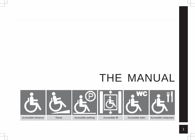
THE MANUAL
Accessible entrance Ramp Accessible lift Accessible toilet Accessible restaurantAccessible parking
2
SI
GN
AG
E
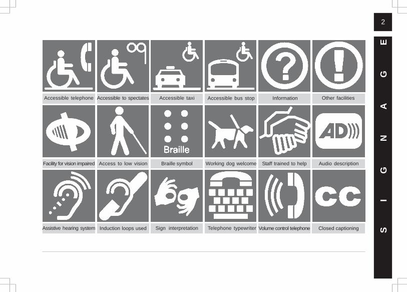
Information
Telephone typewriterInduction loops used Closed captioning
Staff trained to help
Other facilitiesAccessible to spectatesAccessible telephone Accessible bus stopAccessible taxi
Sign interpretation
Audio description
Volume control telephone
Access to low vision Working dog welcomeBraille symbolFacility for vision impaired
Assistive hearing system
3
01- SIGNAGE
1.1 - INTRODUCTION (SIGN TYPES)
-There are four main functional typologies intowhich signage could be classified :
a. Information Signsb. Directional Signsc. Identification ( Locational) Signs andd. Warning ( Safety) Signs.
Information Signs
-These include location signs, sign directories,maps for both internal and external areas fororientation of the user.
Direction Signs
-These signs direct the user to a destination witharrow marks aiding the text.
Identification Signs
-These signs installed at specific individualdestinations indicate the location of a room,service, desk, etc.
Warning ( Safety ) Signs
-Signs installed for the safety of users which maybe either the warning or the prohibitory t y p e .This group would include fire exit signs, safetysigns, etc. and are normally specified by I S Oconventions in terms of colour, size and graphic.These designs should be adhered to and nottampered with in any aspect.
-The graphic qualities of each type depends uponthe intensity of the message and must conform tothem universally to avoid ambiguity. In places usedextensively by persons with a particular disability, thesignage should be appropriately altered to suit them.Signage forms an important part in creating a barrier-free environment and should be treated as such. S
IG
NA
GE
4
-The following internationally specified shapesshould be followed in signboards for varioussigns:
Information signboards – RectangularWarning signboards – TriangularInterdiction signboards – Circular
1.2 - DESIGN CONSIDERATIONS
1.2.1 - General
-Signage should be placed at nodal positions,openly and prominently. They should be simplein syntax and must be well lit in ambient low-light conditions.
-It should not obstruct any movement path and,if suspended, should have a minimum clearhead-room of 2000 mm from the finished floor.
-If the signage is floorbased and free-standing,then there should be a detectable barrier at thefloor level for the white stick users.
-Signage systems should be clear, consistentand in all the comprehensible languages of theregion. Cross signage should be avoided to avoidanxiety and confusion.
-In general, signs should not be placed behindglass panels because of possible reflection andthus making for poor readability.
-Signage placed on pedestrian path of travel areconsidered obstructions; thus they should bedetectable.
1.2.2 - Signage Requirement
-Signs related to barrier-free access are requiredat the following locations: S
IG
NA
GE
5
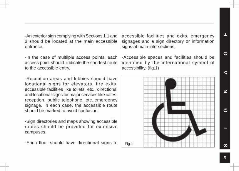
-An exterior sign complying with Sections 1.1 and3 should be located at the main accessibleentrance.
-In the case of multilple access points, eachaccess point should indicate the shortest routeto the accessible entry.
-Reception areas and lobbies should havelocational signs for elevators, fire exits,accessible facilities like toilets, etc., directionaland locational signs for major services like cafes,reception, public telephone, etc.,emergencysignage. In each case, the accessible routeshould be marked to avoid confusion.
-Sign directories and maps showing accessibleroutes should be provided for extensivecampuses.
-Each floor should have directional signs to
accessible facilities and exits, emergencysignages and a sign directory or informationsigns at main intersections.
-Accessible spaces and facilities should beidentified by the international symbol ofaccessibility. (fig.1)
Fig.1 SI
GN
AG
E
6
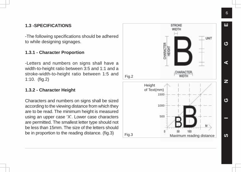
1.3 -SPECIFICATIONS
-The following specifications should be adheredto while designing signages.
1.3.1 - Character Proportion
-Letters and numbers on signs shall have awidth-to-height ratio between 3:5 and 1:1 and astroke-width-to-height ratio between 1:5 and1:10. (fig.2)
1.3.2 - Character Height
Characters and numbers on signs shall be sizedaccording to the viewing distance from which theyare to be read. The minimum height is measuredusing an upper case ‘X’. Lower case charactersare permitted. The smallest letter type should notbe less than 15mm. The size of the letters shouldbe in proportion to the reading distance. (fig.3) Fig.3
Fig.2
SI
GN
AG
E
Heightof Text(mm)
Maximum reading distance
500
1500
1000
7
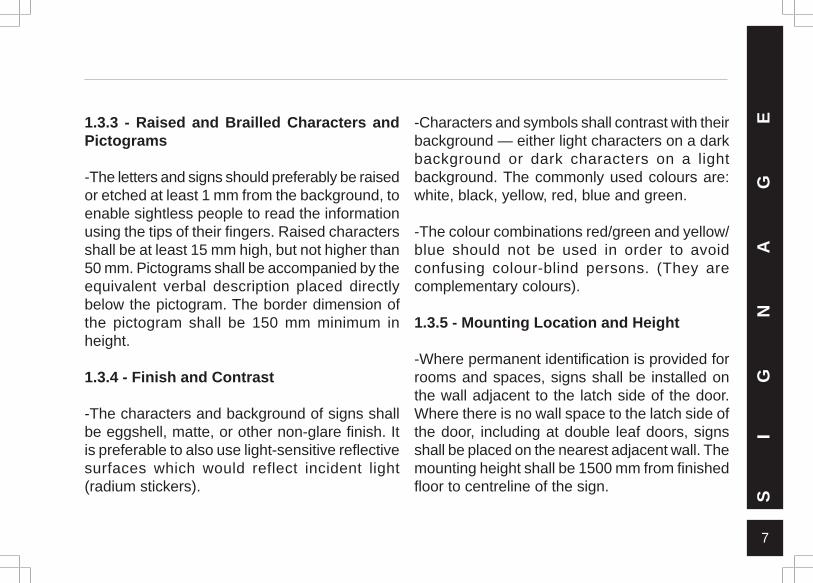
1.3.3 - Raised and Brailled Characters andPictograms
-The letters and signs should preferably be raisedor etched at least 1 mm from the background, toenable sightless people to read the informationusing the tips of their fingers. Raised charactersshall be at least 15 mm high, but not higher than50 mm. Pictograms shall be accompanied by theequivalent verbal description placed directlybelow the pictogram. The border dimension ofthe pictogram shall be 150 mm minimum inheight.
1.3.4 - Finish and Contrast
-The characters and background of signs shallbe eggshell, matte, or other non-glare finish. Itis preferable to also use light-sensitive reflectivesurfaces which would reflect incident light(radium stickers).
-Characters and symbols shall contrast with theirbackground — either light characters on a darkbackground or dark characters on a lightbackground. The commonly used colours are:white, black, yellow, red, blue and green.
-The colour combinations red/green and yellow/blue should not be used in order to avoidconfusing colour-blind persons. (They arecomplementary colours).
1.3.5 - Mounting Location and Height
-Where permanent identification is provided forrooms and spaces, signs shall be installed onthe wall adjacent to the latch side of the door.Where there is no wall space to the latch side ofthe door, including at double leaf doors, signsshall be placed on the nearest adjacent wall. Themounting height shall be 1500 mm from finishedfloor to centreline of the sign.
SI
GN
AG
E
8
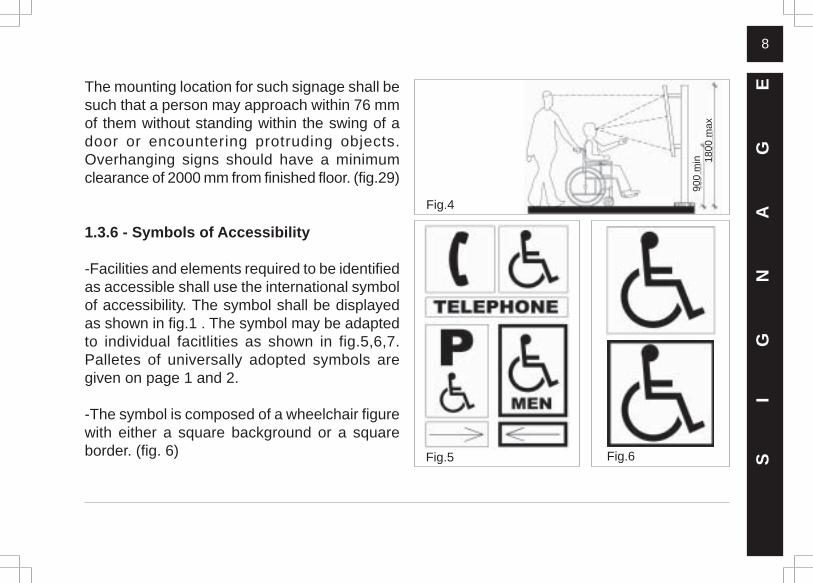
The mounting location for such signage shall besuch that a person may approach within 76 mmof them without standing within the swing of adoor or encountering protruding objects.Overhanging signs should have a minimumclearance of 2000 mm from finished floor. (fig.29)
1.3.6 - Symbols of Accessibility
-Facilities and elements required to be identifiedas accessible shall use the international symbolof accessibility. The symbol shall be displayedas shown in fig.1 . The symbol may be adaptedto individual facitlities as shown in fig.5,6,7.Palletes of universally adopted symbols aregiven on page 1 and 2.
-The symbol is composed of a wheelchair figurewith either a square background or a squareborder. (fig. 6) Fig.5 Fig.6 S
IG
NA
GE
Fig.4
1800
max
900
min
9
-Contrasting colours should be used todifferentiate the figure from the background. Thecommonly employed colours are white for thefigure and blue for the background.
-The wheelchair figure should always face theright..
-For completely accessible buildings, it is enoughto have one explanatory sign at the entrance.
1.3.7 - Illumination Levels
-Illumination levels on the sign surface shall bein the 100 to 300 lux range and shall be uniform.Signs shall be located such that the illuminationlevel on the surface of the sign is not significantlyexceeded by the ambient light or a visible brightlighting source behind or in front of it.
1.4 - SIGNAGE DESIGN
1.4.1 - Language
-Clear, unambiguous messages in simple,understandable fonts and formats.
-Legibility improves if every key word begins witha capital letter.
-The exceptions are standard words like STOP,EXIT, BUS, etc.
-Use punctuations sparingly and avoid the useof full stops at the end of the sentence.
-Signages leading to two destinations should bekept on separate lines for easier legibility.
-Avoid abbreviations as they can be easilymisinterpreted.
SI
GN
AG
E
10
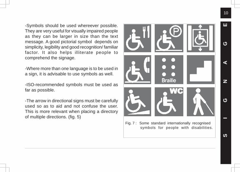
-Symbols should be used whereever possible.They are very useful for visually impaired peopleas they can be larger in size than the textmessage. A good pictorial symbol depends onsimplicity, legibility and good recognition/ familiarfactor. It also helps illiterate people tocomprehend the signage.
-Where more than one language is to be used ina sign, it is advisable to use symbols as well.
-ISO-recommended symbols must be used asfar as possible.
-The arrow in directional signs must be carefullyused so as to aid and not confuse the user.This is more relevant when placing a directoryof multiple directions. (fig. 5)
SI
GN
AG
E
Fig. 7 : Some standard internationally recognised symbols for people with disabilities.
11
1.4.3 - Sizes for Letters and Symbols
(Minimum character size)
-At building entrances, house numbers andsimilar : 150 mm
-Identification or direction signs : 50 ~ 100 mm
-Sign directories : 25~50 mm
-Symbols should be at least 100mm in height.
-Braille should be incorporated in the signs.Round dots which should be raised 0.46mm mustbe placed below the text (or symbol) and rangedfrom left.
- A Braille locator (either raised or recessedshould also be incorporated in the sign to enablethe visually impaired to be guided to the Braillemessage. S
IG
NA
GE1.4.2 - Sign Typeface
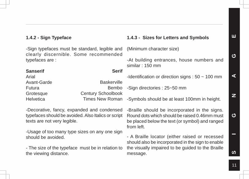
-Sign typefaces must be standard, legible andclearly discernible. Some recommendedtypefaces are :
SanserifArialAvant-GardeFuturaGrotesqueHelvetica
-Decorative, fancy, expanded and condensedtypefaces should be avoided. Also Italics or scripttexts are not very legible.
-Usage of too many type sizes on any one signshould be avoided.
- The size of the typeface must be in relation tothe viewing distance.
Serif
BaskervilleBembo
Century SchoolbookTimes New Roman
12
1.4.4 - Text Design
-Legibility also depends on inter characterspacing, word spacing and line spacing.
-For visually impaired people it is desirable toincrease the inter character, word and linespacing by 20 percent to 30 percent.
-Text aligned left is the easiest to read and isrecommended in most cases except in directionsigns where both left and right arrows are beingused and the text should correspondingly be leftor right aligned.
-Locational signs can be centre aligned.
-Both upper and lower cases must be used asthey tend to be more legible than a message inall caps or all small letter forms.
1.4.5 - Colour and Contrast
-The colour and contrast should depend onexternal factors such as background, location,etc. A blue sign on a blue wall will obviously beof little help.
-A border around the sign can be useful inincreasing the readability as long as the borderwidth is not over powering.
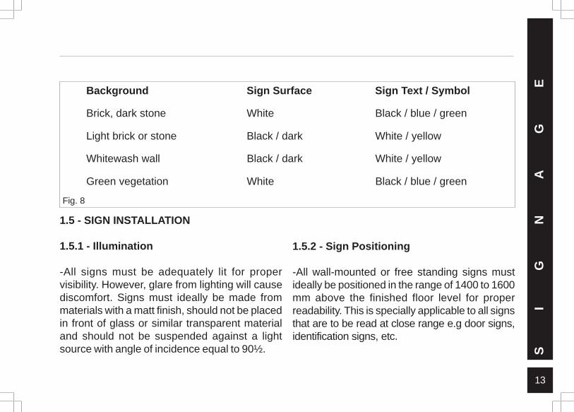
The chart (fig.8) on page 13 recommends somecolour combinations:
SI
GN
AG
E
13
Background Sign Surface Sign Text / Symbol
Brick, dark stone White Black / blue / green
Light brick or stone Black / dark White / yellow
Whitewash wall Black / dark White / yellow
Green vegetation White Black / blue / green
1.5 - SIGN INSTALLATION
1.5.1 - Illumination
-All signs must be adequately lit for propervisibility. However, glare from lighting will causediscomfort. Signs must ideally be made frommaterials with a matt finish, should not be placedin front of glass or similar transparent materialand should not be suspended against a lightsource with angle of incidence equal to 90½.
1.5.2 - Sign Positioning
-All wall-mounted or free standing signs mustideally be positioned in the range of 1400 to 1600mm above the finished floor level for properreadability. This is specially applicable to all signsthat are to be read at close range e.g door signs,identification signs, etc.
Fig. 8
SI
GN
AG
E
14
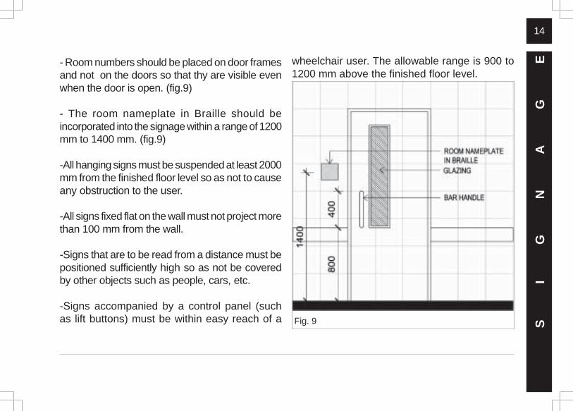
- Room numbers should be placed on door framesand not on the doors so that thy are visible evenwhen the door is open. (fig.9)
- The room nameplate in Braille should beincorporated into the signage within a range of 1200mm to 1400 mm. (fig.9)
-All hanging signs must be suspended at least 2000mm from the finished floor level so as not to causeany obstruction to the user.
-All signs fixed flat on the wall must not project morethan 100 mm from the wall.
-Signs that are to be read from a distance must bepositioned sufficiently high so as not be coveredby other objects such as people, cars, etc.
-Signs accompanied by a control panel (suchas lift buttons) must be within easy reach of a
wheelchair user. The allowable range is 900 to1200 mm above the finished floor level.
Fig. 9 SI
GN
AG
E
15
02- BASIC ANTHROPOMETRICS
2.1 - REACH RANGES2.1.1 - Forward Reach
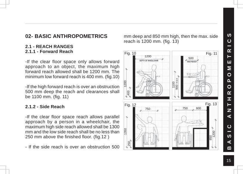
-If the clear floor space only allows forwardapproach to an object, the maximum highforward reach allowed shall be 1200 mm. Theminimum low forward reach is 400 mm. (fig.10)
-If the high forward reach is over an obstruction500 mm deep the reach and clearances shallbe 1100 mm. (fig. 11)
2.1.2 - Side Reach
-If the clear floor space reach allows parallelapproach by a person in a wheelchair, themaximum high side reach allowed shall be 1300mm and the low side reach shall be no less than250 mm above the finished floor. (fig.12 )
- If the side reach is over an obstruction 500
mm deep and 850 mm high, then the max. sidereach is 1200 mm. (fig. 13)
BA
SI
C
AN
TH
RO
PO
ME
TR
IC
S
850 12
00
Fig. 13750 600
250
1350
Fig. 12750
1200
400
Fig. 101200
Fig. 11
1100
900
500
16
2.2 - WHITE CANE RANGE
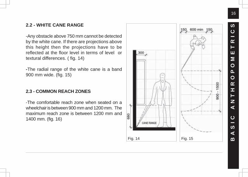
-Any obstacle above 750 mm cannot be detectedby the white cane. If there are projections abovethis height then the projections have to bereflected at the floor level in terms of level ortextural differences. ( fig. 14)
-The radial range of the white cane is a band900 mm wide. (fig. 15)
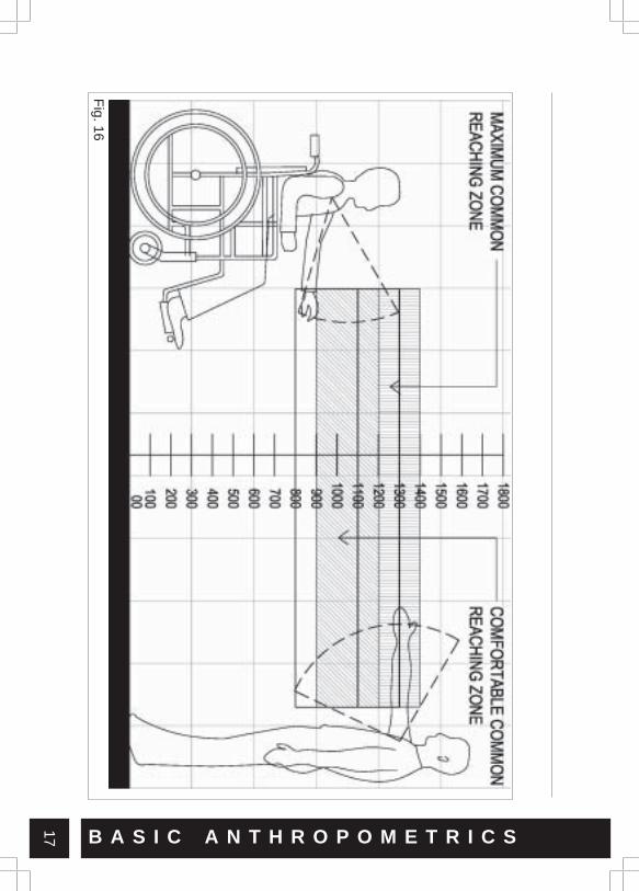
2.3 - COMMON REACH ZONES
-The comfortable reach zone when seated on awheelchair is between 900 mm and 1200 mm. Themaximum reach zone is between 1200 mm and1400 mm. (fig. 16)
BA
SI
C
AN
TH
RO
PO
ME
TR
IC
S
Fig. 15Fig. 14
17
Fig. 16
B A S I C A N T H R O P O M E T R I C S
18
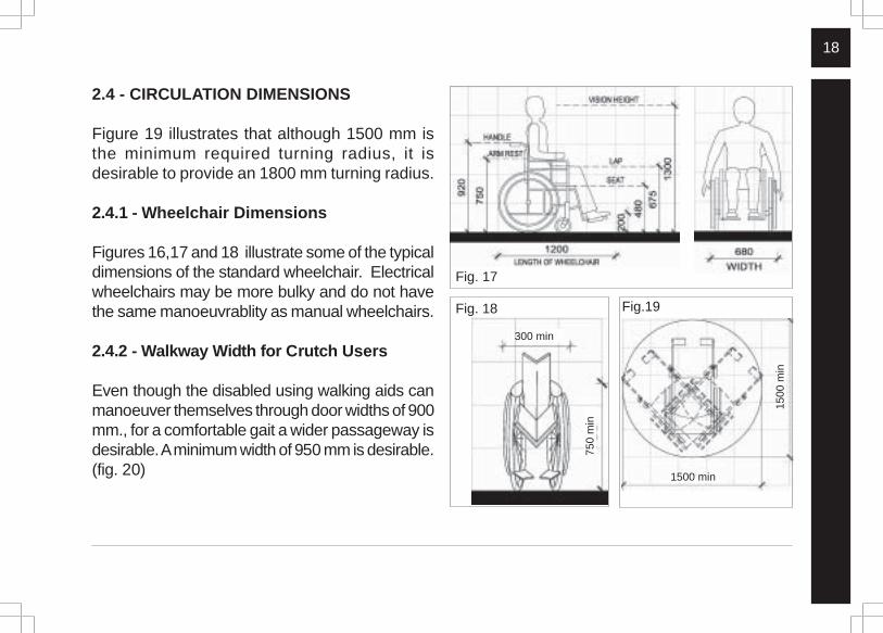
2.4 - CIRCULATION DIMENSIONS
Figure 19 illustrates that although 1500 mm isthe minimum required turning radius, it isdesirable to provide an 1800 mm turning radius.
2.4.1 - Wheelchair Dimensions
Figures 16,17 and 18 illustrate some of the typicaldimensions of the standard wheelchair. Electricalwheelchairs may be more bulky and do not havethe same manoeuvrablity as manual wheelchairs.
2.4.2 - Walkway Width for Crutch Users
Even though the disabled using walking aids canmanoeuver themselves through door widths of 900mm., for a comfortable gait a wider passageway isdesirable. A minimum width of 950 mm is desirable.(fig. 20)
Fig. 17
Fig.19
1500
min
Fig. 18
1500 min
750
min
300 min
19
BA
SI
C
AN
TH
RO
PO
ME
TR
IC
S
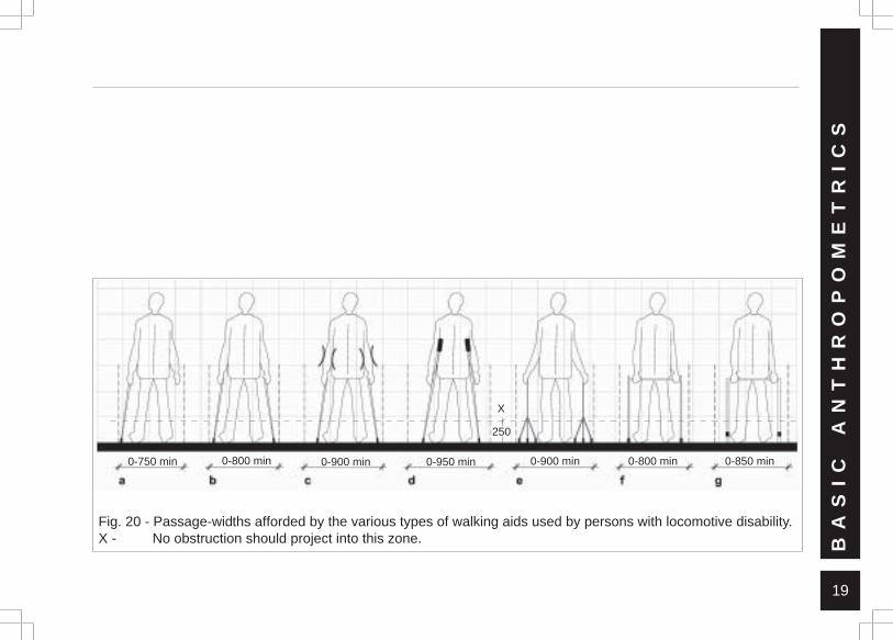
Fig. 20 - Passage-widths afforded by the various types of walking aids used by persons with locomotive disability.X - No obstruction should project into this zone.
250
X
0-750 min 0-800 min 0-900 min 0-950 min 0-900 min 0-800 min 0-850 min
20
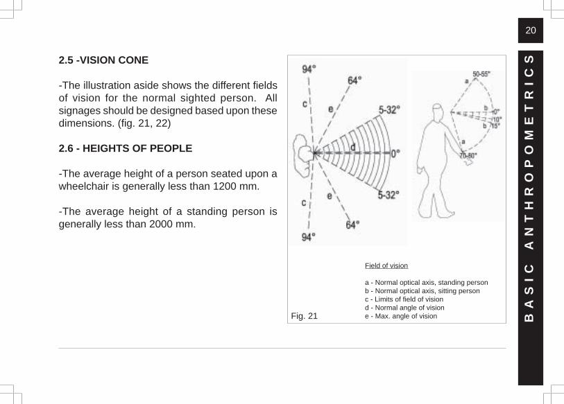
2.5 -VISION CONE
-The illustration aside shows the different fieldsof vision for the normal sighted person. Allsignages should be designed based upon thesedimensions. (fig. 21, 22)
2.6 - HEIGHTS OF PEOPLE
-The average height of a person seated upon awheelchair is generally less than 1200 mm.
-The average height of a standing person isgenerally less than 2000 mm.
Fig. 21 BA
SI
C
AN
TH
RO
PO
ME
TR
IC
S
Field of vision
a - Normal optical axis, standing personb - Normal optical axis, sitting personc - Limits of field of visiond - Normal angle of visione - Max. angle of vision
21
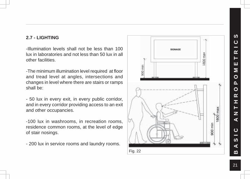
2.7 - LIGHTING
-Illumination levels shall not be less than 100lux in laboratories and not less than 50 lux in allother facilities.
-The minimum illumination level required at floorand tread level at angles, intersections andchanges in level where there are stairs or rampsshall be:
- 50 lux in every exit, in every public corridor,and in every corridor providing access to an exitand other occupancies.
-100 lux in washrooms, in recreation rooms,residence common rooms, at the level of edgeof stair nosings.
- 200 lux in service rooms and laundry rooms.
Fig. 22 BA
SI
C
AN
TH
RO
PO
ME
TR
IC
S
900
min 18
00 m
ax
22
SP
AC
E
A
LL
OW
AN
CE
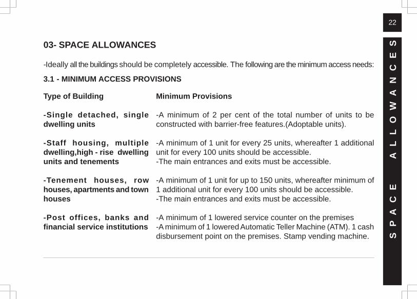
S03- SPACE ALLOWANCES
-Ideally all the buildings should be completely accessible. The following are the minimum access needs:
Type of Building
-Single detached, singledwelling units
-Staff housing, multipledwelling,high - rise dwellingunits and tenements
-Tenement houses, rowhouses, apartments and townhouses
-Post offices, banks andfinancial service institutions
Minimum Provisions
-A minimum of 2 per cent of the total number of units to beconstructed with barrier-free features.(Adoptable units).
-A minimum of 1 unit for every 25 units, whereafter 1 additionalunit for every 100 units should be accessible.-The main entrances and exits must be accessible.
-A minimum of 1 unit for up to 150 units, whereafter minimum of1 additional unit for every 100 units should be accessible.-The main entrances and exits must be accessible.
-A minimum of 1 lowered service counter on the premises-A minimum of 1 lowered Automatic Teller Machine (ATM). 1 cashdisbursement point on the premises. Stamp vending machine.
3.1 - MINIMUM ACCESS PROVISIONS
23
-Shophouses and single-storey shops
-Places of worship
-Food centres
-Community centres, villagehalls, auditoria, concert halls,assembly halls, cinemas,theatres and other places ofpublic assembly.
-Accessible shopping area.
-Entrance and exit and the main area of worship to be accessible.-Mosques : Access to area for ablutions.-Churches : Access to confessionals, fonts and chapels.-Temples : Access to shrines and courtyards.
-A minimum of 1 table without stools or seats attached to thefloor for every 10 tables. A minimum of 2 tables without stools orseats attached to the floor for the whole premises
-Accessible entrances, exits, aisles and main community or publicgathering areas.-Accessible toilet facilities should be near by.-Seating for persons with disablities should be accessible frommain entrances and lobbies.-Various seating/viewing choices to be provided for persons inwheelchairs throughout the main seating area.-A minimum of 2 wheelchair spaces for a seating capacity of upto 100 seats and 4 wheelchair spaces for seating capacity fromover 100 to 400 seats.
SP
AC
E
A
LL
OW
AN
CE
S
24
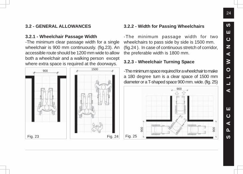
3.2 - GENERAL ALLOWANCES
3.2.1 - Wheelchair Passage Width-The minimum clear passage width for a singlewheelchair is 900 mm continuously. (fig.23). Anaccessible route should be 1200 mm wide to allowboth a wheelchair and a walking person exceptwhere extra space is required at the doorways.
3.2.2 - Width for Passing Wheelchairs
-The minimum passage width for twowheelchairs to pass side by side is 1500 mm.(fig.24 ). In case of continuous stretch of corridor,the preferable width is 1800 mm.
3.2.3 - Wheelchair Turning Space
-The minimum space required for a wheelchair to makea 180 degree turn is a clear space of 1500 mmdiameter or a T-shaped space 900 mm. wide. (fig. 25)
Fig. 23 Fig. 24 SP
AC
E
A
LL
OW
AN
CE
S
900
900
900
1500900
Fig. 25
25
SP
AC
E
A
LL
OW
AN
CE
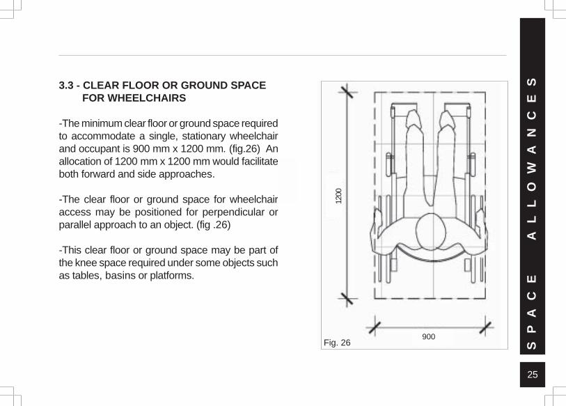
S3.3 - CLEAR FLOOR OR GROUND SPACE FOR WHEELCHAIRS
-The minimum clear floor or ground space requiredto accommodate a single, stationary wheelchairand occupant is 900 mm x 1200 mm. (fig.26) Anallocation of 1200 mm x 1200 mm would facilitateboth forward and side approaches.
-The clear floor or ground space for wheelchairaccess may be positioned for perpendicular orparallel approach to an object. (fig .26)
-This clear floor or ground space may be part ofthe knee space required under some objects suchas tables, basins or platforms.
90012
00Fig. 26
26S P A C E A L L O W A N C E S
27
04 - ACCESSIBLE ROUTES
-All areas of newly designed or newly constructedbuildings and facilities (walks, halls, corridors,aisles, skywalks, tunnels, and other spaces)required to be accessible by general public shallbe made barrier-free.
-Detectable warnings required shall comply withSection 4.3.5
4.1 - PHYSICAL PARAMETERS
4.1.1 - Location
-At least one accessible route complying withSection 3 shall be provided within the boundaryof the site from public transportation stops,accessible parking spaces, passenger loadingzones, and public streets or sidewalks to anaccessible building entrance they serve.
-The accessible route shall, to the maximumextent feasible, coincide with the route for thegeneral public.
-At least one accessible route shall connectaccessible buildings or facility entrances with allaccessible spaces and elements on the same site.
-At least one accessible route shall connectaccessible buildings or facility entrances with allaccessible dwelling units within the building or facility.
-An accessible route shall connect at least oneaccessible entrance of each accessible dwellingunit with those exterior and interior spaces andfacilities that serve the accessible dwelling unit.
-Ground and floor surfaces along accessibleroutes should comply with the specifications inSection 3.2, have discernible colours and nonslippery materials. Demarcation can be made
AC
CE
SS
IB
LE
RO
UT
ES
28
with textural differences too. Appropriate signagecomplying with Section 1 should be placed toindicate the position of this route.
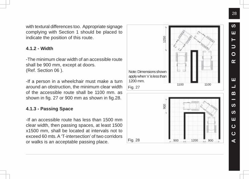
4.1.2 - Width
-The minimum clear width of an accessible routeshall be 900 mm, except at doors.(Ref. Section 06 ).
-If a person in a wheelchair must make a turnaround an obstruction, the minimum clear widthof the accessible route shall be 1100 mm. asshown in fig. 27 or 900 mm as shown in fig.28.
4.1.3 - Passing Space
-If an accessible route has less than 1500 mmclear width, then passing spaces, at least 1500x1500 mm, shall be located at intervals not toexceed 60 mts. A ‘T-intersection’ of two corridorsor walks is an acceptable passing place.
Fig. 27
Fig. 28 AC
CE
SS
IB
LE
RO
UT
ES
900 1200 900
900
1100 1100
1250
Note: Dimensions shownapply when ‘x’ is less than1200 mm.
29
Protect shaded areafrom cross traffic.
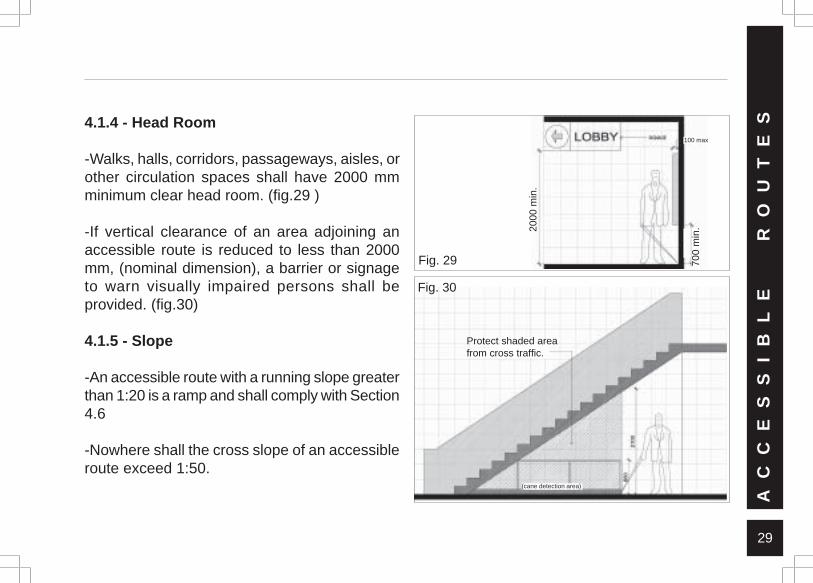
4.1.4 - Head Room
-Walks, halls, corridors, passageways, aisles, orother circulation spaces shall have 2000 mmminimum clear head room. (fig.29 )
-If vertical clearance of an area adjoining anaccessible route is reduced to less than 2000mm, (nominal dimension), a barrier or signageto warn visually impaired persons shall beprovided. (fig.30)
4.1.5 - Slope
-An accessible route with a running slope greaterthan 1:20 is a ramp and shall comply with Section4.6
-Nowhere shall the cross slope of an accessibleroute exceed 1:50.
Fig. 30
AC
CE
SS
IB
LE
RO
UT
ES
Fig. 29
2000
min
.
700
min
100 max
(cane detection area)
2000
min
.
700
min
.
30
4.1.6 - Changes in Levels
-If an accessible route has changes in levelgreater than 12 mm, then a curb ramp, ramp,elevator, or platform lift (as permitted in Section3.1) shall be provided that complies with Sections4.5, 4.6, 4.8 or 4.9 respectively.
-An accessible route does not include stairs,steps, or escalators.
4.1.7- Guiding Blocks
-Guiding blocks complying with Section 4.3.5shall be provided at all crucial locations alongthe accessible route.
4.1.8 - Signage
-The universal standard colour contrast code ofwhite and blue should be followed in all the
signages and all numeric as well as alphabeticalinformation sources. All signages should followSection 01 for specifications.
AC
CE
SS
IB
LE
RO
UT
ES
31
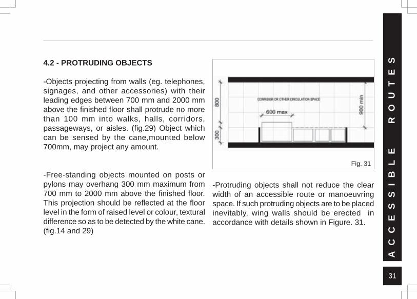
4.2 - PROTRUDING OBJECTS
-Objects projecting from walls (eg. telephones,signages, and other accessories) with theirleading edges between 700 mm and 2000 mmabove the finished floor shall protrude no morethan 100 mm into walks, halls, corridors,passageways, or aisles. (fig.29) Object whichcan be sensed by the cane,mounted below700mm, may project any amount.
-Free-standing objects mounted on posts orpylons may overhang 300 mm maximum from700 mm to 2000 mm above the finished floor.This projection should be reflected at the floorlevel in the form of raised level or colour, texturaldifference so as to be detected by the white cane.(fig.14 and 29)
Fig. 31
-Protruding objects shall not reduce the clearwidth of an accessible route or manoeuvringspace. If such protruding objects are to be placedinevitably, wing walls should be erected inaccordance with details shown in Figure. 31.
AC
CE
SS
IB
LE
RO
UT
ES
32
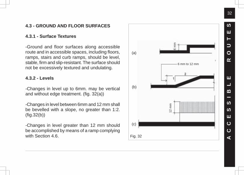
4.3 - GROUND AND FLOOR SURFACES
4.3.1 - Surface Textures
-Ground and floor surfaces along accessibleroute and in accessible spaces, including floors,ramps, stairs and curb ramps, should be level,stable, firm and slip-resistant. The surface shouldnot be excessively textured and undulating.
4.3.2 - Levels
-Changes in level up to 6mm. may be verticaland without edge treatment. (fig. 32(a))
-Changes in level between 6mm and 12 mm shallbe bevelled with a slope, no greater than 1:2.(fig.32(b))
-Changes in level greater than 12 mm shouldbe accomplished by means of a ramp complyingwith Section 4.6. Fig. 32
(a)
(b)
(c)
AC
CE
SS
IB
LE
RO
UT
ES
6 m
m
6 mm to 12 mm
12 m
m
33
4.3.3 - Carpets
-If carpets or carpet-tiles are used on a groundor floor surface, then it shall be securely attached:have a firm cushion, pad or backing and mustleave a level loop, textured loop or level cut /uncut pile texture. (fig.32(c))
-The maximum pile thickness shall be 12 mm.
-The exposed edges of carpet shall be fastenedto floor surfaces and should be trimmed alongthe entire length of the exposed edge.
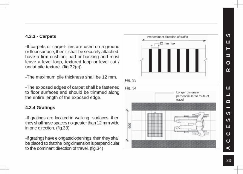
4.3.4 Gratings
-If gratings are located in walking surfaces, thenthey shall have spaces no greater than 12 mm widein one direction. (fig.33)
-If gratings have elongated openings, then they shallbe placed so that the long dimension is perpendicularto the dominant direction of travel. (fig.34)
Fig. 33
Predominant direction of traffic
12 mm max.
Fig. 34
AC
CE
SS
IB
LE
RO
UT
ES
12 mm max
Longer dimensionperpendicular to route oftravel
34
4.3.5 - Guiding Blocks(Detectable Warnings)
4.3.5.1 - Walking Surfaces
-Detectable warnings shall consist of raisedtruncated domes with a diameter of nominal 24mm, a height of nominal 5 mm and a centre-to-centre spacing of nominal 60 mm and shallcontrast visually with adjoining surfaces, eitherlight-on-dark or dark-on-light.
-The material used to provide contrast shall bean integral part of the walking surface.
-Detectable warnings used on interior surfacesshall differ from adjoining surfaces in resilienceor sound-on-cane contact.
4.3.5.2 - Vehicular Areas
-If a walk crosses or adjoins a vehicular way,and the walking surfaces are not separated bycurbs, railings or any other elements betweenthe pedestrian areas and vehicular areas, theboundary between the areas shall be definedby a continuous detectable warning strip pathwhich is 900 mm wide, with devices complyingwith Section 4.3.5.1
4.3.5.3 - Reflecting Pools
-The edges of reflecting pools must be protectedby railings, walls, curbs or detectable warningscomplying with Section 4.3.5.1
AC
CE
SS
IB
LE
RO
UT
ES
35
4.4 - VEHICULAR PARKING ANDPASSENGER LOADING ZONES
4.4.1- Location
-Accessible parking spaces serving a particularbuilding shall be located on the shortest accessibleroute of travel from adjacent parking to anaccessible entrance.
-In parking facilities that do not serve a particularbuilding, accessible parking shall be located on theshortest accessible route of travel to an accessiblepedestrian entrance to the parking facility.
-In buildings with multiple accessible entrances withadjacent parking, accessible parking spaces shallbe dispersed and located closest to the accessibleentrances.
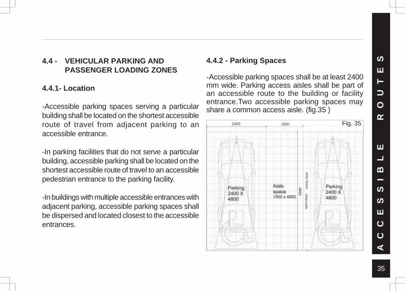
4.4.2 - Parking Spaces
-Accessible parking spaces shall be at least 2400mm wide. Parking access aisles shall be part ofan accessible route to the building or facilityentrance.Two accessible parking spaces mayshare a common access aisle. (fig.35 )
AC
CE
SS
IB
LE
RO
UT
ES
2400 1500
4800
AIS
LE S
PAC
E - 1500 w
idthA
isle Space
Fig. 35
36
-Parked vehicle overhangs shall not reduce theclear width of an accessible route.
-Parking spaces and access aisles shall be levelwith surface slopes not exceeding 1:50 (2 percent) in all directions.
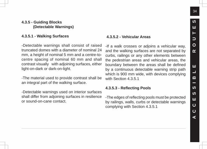
4.4.3 - Passenger Loading Zones
-Passenger loading zones shall provide anaccess aisle at least 1500 mm wide and 4800mm long adjacent and parallel to the vehiclepull-up space. (fig.36)
-If there are curbs between the access aisle andthe vehicle pull-up space, then a curb rampcomplying with Section 4.5 shall be provided.
-Vehicle standing spaces and access aislesshall be level with surface slopes not exceeding1:50 (2 per cent) in all directions.
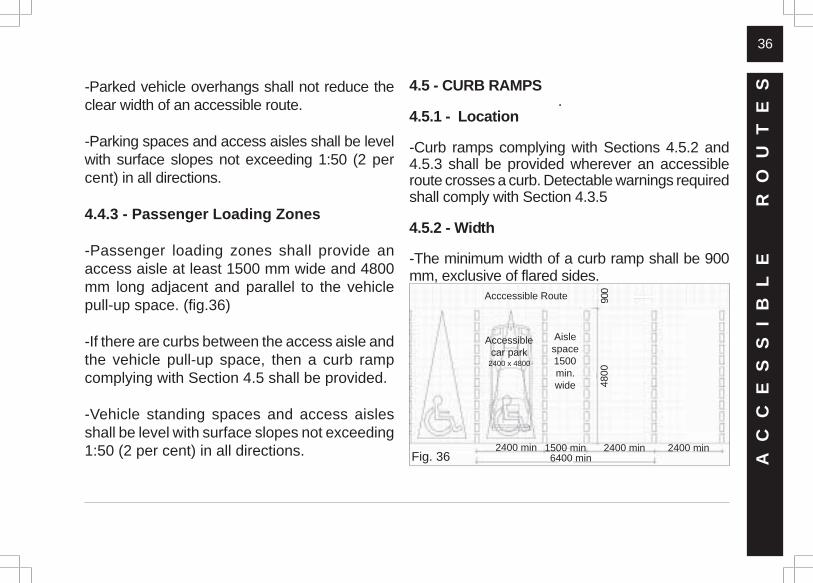
4.5 - CURB RAMPS .4.5.1 - Location
-Curb ramps complying with Sections 4.5.2 and4.5.3 shall be provided wherever an accessibleroute crosses a curb. Detectable warnings requiredshall comply with Section 4.3.5
4.5.2 - Width
-The minimum width of a curb ramp shall be 900mm, exclusive of flared sides.
AC
CE
SS
IB
LE
RO
UT
ES
4800
900Acccessible Route
Aislespace1500min.wide
Accessiblecar park
2400 x 4800
2400 min 1500 min 2400 min6400 min
2400 minFig. 36
37
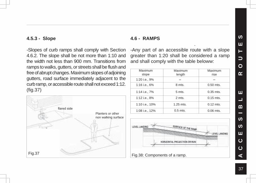
4.5.3 - Slope
-Slopes of curb ramps shall comply with Section4.6.2. The slope shall be not more than 1:10 andthe width not less than 900 mm. Transitions fromramps to walks, gutters, or streets shall be flush andfree of abrupt changes. Maximum slopes of adjoininggutters, road surface immediately adjacent to thecurb ramp, or accessible route shall not exceed 1:12.(fig.37)
4.6 - RAMPS .-Any part of an accessible route with a slopegreater than 1:20 shall be considered a rampand shall comply with the table beloww:
Fig.38: Components of a ramp.Fig.37 AC
CE
SS
IB
LE
RO
UT
ES
Maximumslope
Maximumlength
Maximumrise
1:20 i.e., 9%
1:16 i.e., 6%
1:14 i.e., 7%
1:12 i.e., 8%
1:10 i.e., 10%
1:08 i.e., 12%
--
8 mts.
5 mts.
2 mts.
1.25 mts.
--
0.50 mts.
0.35 mts.
0.15 mts.
0.12 mts.
0.06 mts.0.5 mts.flared side
Planters or othernon walking surface
38
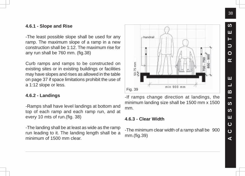
4.6.1 - Slope and Rise
-The least possible slope shall be used for anyramp. The maximum slope of a ramp in a newconstruction shall be 1:12. The maximum rise forany run shall be 760 mm. (fig.38)
Curb ramps and ramps to be constructed onexisting sites or in existing buildings or facilitiesmay have slopes and rises as allowed in the tableon page 37 if space limitations prohibit the use ofa 1:12 slope or less.
4.6.2 - Landings
-Ramps shall have level landings at bottom andtop of each ramp and each ramp run, and atevery 10 mts of run.(fig. 38)
-The landing shall be at least as wide as the ramprun leading to it. The landing length shall be aminimum of 1500 mm clear. A
CC
ES
SI
BL
E
R
OU
TE
S
-If ramps change direction at landings, theminimum landing size shall be 1500 mm x 1500mm.
4.6.3 - Clear Width
-The minimum clear width of a ramp shall be 900mm.(fig.39)
handrail
50-7
5 m
m
Fig. 39
39
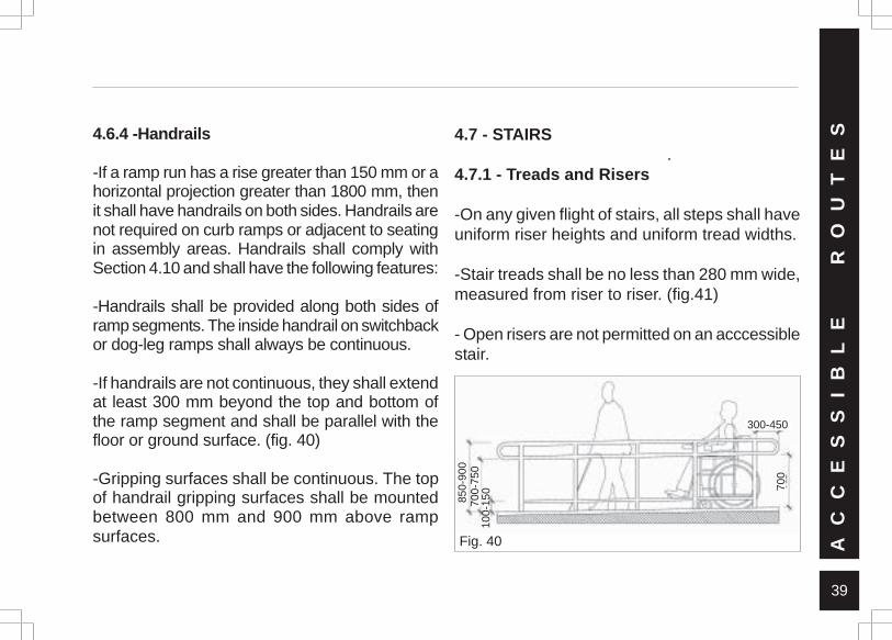
4.6.4 -Handrails
-If a ramp run has a rise greater than 150 mm or ahorizontal projection greater than 1800 mm, thenit shall have handrails on both sides. Handrails arenot required on curb ramps or adjacent to seatingin assembly areas. Handrails shall comply withSection 4.10 and shall have the following features:
-Handrails shall be provided along both sides oframp segments. The inside handrail on switchbackor dog-leg ramps shall always be continuous.
-If handrails are not continuous, they shall extendat least 300 mm beyond the top and bottom ofthe ramp segment and shall be parallel with thefloor or ground surface. (fig. 40)
-Gripping surfaces shall be continuous. The topof handrail gripping surfaces shall be mountedbetween 800 mm and 900 mm above rampsurfaces. A
CC
ES
SI
BL
E
R
OU
TE
S4.7 - STAIRS .4.7.1 - Treads and Risers
-On any given flight of stairs, all steps shall haveuniform riser heights and uniform tread widths.
-Stair treads shall be no less than 280 mm wide,measured from riser to riser. (fig.41)
- Open risers are not permitted on an acccessiblestair.
Fig. 40
850-
900
700-
750
100-
150 70
0
300-450
40
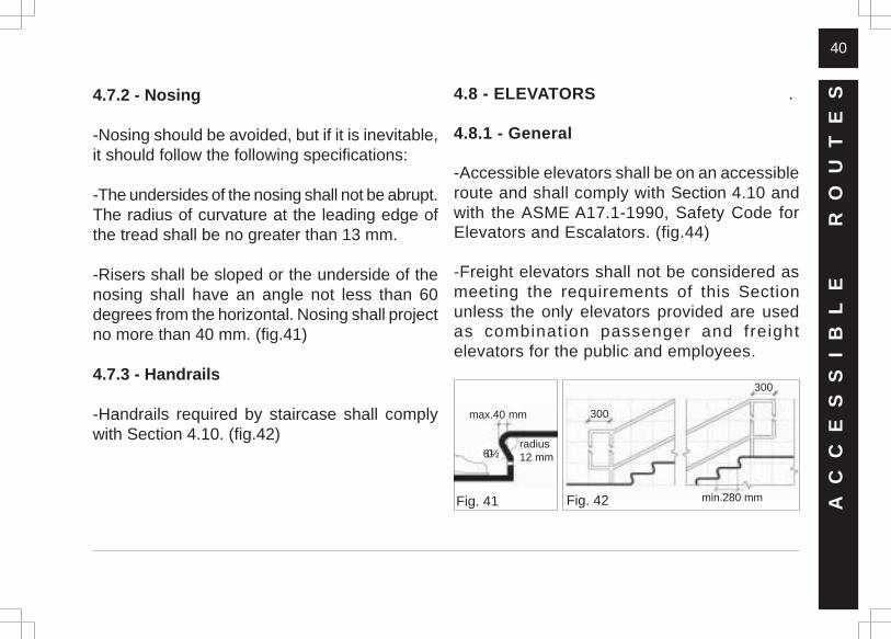
4.7.2 - Nosing
-Nosing should be avoided, but if it is inevitable,it should follow the following specifications:
-The undersides of the nosing shall not be abrupt.The radius of curvature at the leading edge ofthe tread shall be no greater than 13 mm.
-Risers shall be sloped or the underside of thenosing shall have an angle not less than 60degrees from the horizontal. Nosing shall projectno more than 40 mm. (fig.41)
4.7.3 - Handrails
-Handrails required by staircase shall complywith Section 4.10. (fig.42)
4.8 - ELEVATORS .
4.8.1 - General
-Accessible elevators shall be on an accessibleroute and shall comply with Section 4.10 andwith the ASME A17.1-1990, Safety Code forElevators and Escalators. (fig.44)
-Freight elevators shall not be considered asmeeting the requirements of this Sectionunless the only elevators provided are usedas combination passenger and freightelevators for the public and employees.
AC
CE
SS
IB
LE
RO
UT
ES
Fig. 41
max.40 mm
60½radius12 mm
300
300
min.280 mmFig. 42
41
4.8.2 - Automatic Operation
-Elevator operation shall be automatic. Each carshall be equipped with a self-levelling feature thatwill automatically bring the car to floor landingswithin a tolerance of 13 mm under rated loadingto zero loading conditions.
-This self-levelling feature shall be automatic andindependent of the operating device, and shallcorrect the over travel or under travel.
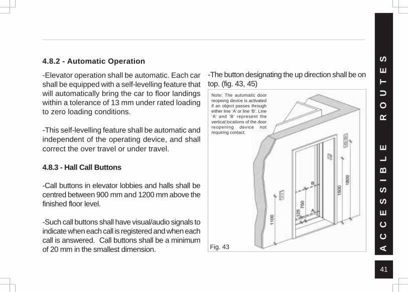
4.8.3 - Hall Call Buttons
-Call buttons in elevator lobbies and halls shall becentred between 900 mm and 1200 mm above thefinished floor level.
-Such call buttons shall have visual/audio signals toindicate when each call is registered and when eachcall is answered. Call buttons shall be a minimumof 20 mm in the smallest dimension.
Note: The automatic doorreopeing device is activatedif an object passes througheither line ‘A’ or line ‘B’. Line‘A’ and ‘B’ represent thevertical locations of the doorreopening device notrequiring contact.
Fig. 43
-The button designating the up direction shall be ontop. (fig. 43, 45)
AC
CE
SS
IB
LE
RO
UT
ES
42
2000
900 min
1300
min
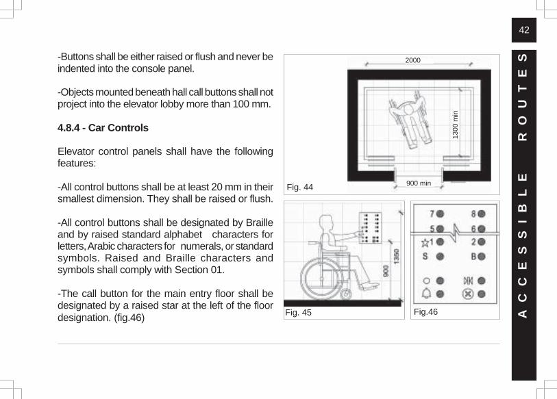
-Buttons shall be either raised or flush and never beindented into the console panel.
-Objects mounted beneath hall call buttons shall notproject into the elevator lobby more than 100 mm.
4.8.4 - Car Controls
Elevator control panels shall have the followingfeatures:
-All control buttons shall be at least 20 mm in theirsmallest dimension. They shall be raised or flush.
-All control buttons shall be designated by Brailleand by raised standard alphabet characters forletters, Arabic characters for numerals, or standardsymbols. Raised and Braille characters andsymbols shall comply with Section 01.
-The call button for the main entry floor shall bedesignated by a raised star at the left of the floordesignation. (fig.46) Fig. 45 Fig.46
Fig. 44
AC
CE
SS
IB
LE
RO
UT
ES
43
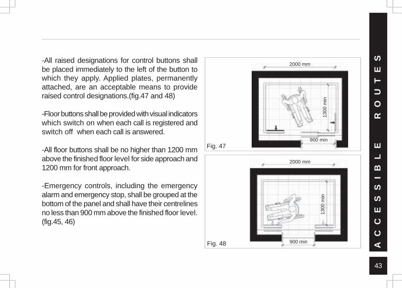
-All raised designations for control buttons shallbe placed immediately to the left of the button towhich they apply. Applied plates, permanentlyattached, are an acceptable means to provideraised control designations.(fig.47 and 48)
-Floor buttons shall be provided with visual indicatorswhich switch on when each call is registered andswitch off when each call is answered.
-All floor buttons shall be no higher than 1200 mmabove the finished floor level for side approach and1200 mm for front approach.
-Emergency controls, including the emergencyalarm and emergency stop, shall be grouped at thebottom of the panel and shall have their centrelinesno less than 900 mm above the finished floor level.(fig.45, 46)
Fig. 48
Fig. 47
AC
CE
SS
IB
LE
RO
UT
ES
900 min
2000 mm
2000 mm
900 min
1300
min
1300
min
44
AC
CE
SS
IB
LE
RO
UT
ES4.8.5 - Audio & Visual Signals
- A visible and audible signal shall be providedat each hoist-way entrance to indicate which caris answering a call. Audible signals can soundonce for the up direction and twice for the downdirection or shall have verbal enunciators thatsay “UP” or “DOWN”.
Visible signals shall have the following features:
- 1. Hall lantern fixtures shall be mounted so thattheir centreline is at least 1800 m above the lobbyfloor. (fig.43)
- 2. Visual elements shall be at least 65 mm inthe smallest dimension.
- 3. Signals shall be visible from the vicinity ofthe hall call button. (fig.43 ) In-car lanternslocated in cars, visible from the vicinity of hallcall buttons, and conforming to the aboverequirements, shall be acceptable.
4.8.6 - Raised and Braille Characters on theHoist-way Entrances
- All hoist-way entrances shall have raised andBraille floor designations provided on both jambs.The centreline of the characters shall be 1500mm above the finished floor level. Suchcharacters shall be 50 mm high and shall complywith Section 01. (fig. 43)
4.8.7 - Door Delay for Car Calls
- The minimum time for elevator doors to remainfully open in response to a car call shall be 3seconds.
4.8.8 - Specifications for Car Dimensions
- The floor area of elevator cars shall providespace for wheelchair users to enter the car,manoeuvre within reach of controls, and exit from
45
AC
CE
SS
IB
LE
RO
UT
ESthe car. Acceptable door opening for the car is
900 mm. minimum. Inner dimensions shall be1300 mm x 2000 mm. minimum clear. (fig.44)
- The clearance between the car platform sill andthe edge of any hoist-way landing shall be nogreater than 30 mm.
4.8.9 - Floor and Wall Specifications forthe Car
- Floor surfaces shall comply with Section 4.3.A mirror should be placed on back wall of the liftcar, for additional visibility for the wheelchairusers while backing out of the car.
4.8.10 - Illumination Levels
- The level of illumination at the car controls,platform, car threshold and landing sill shall beat least 53.8 lux (5 foot-candles).
4.9 - PLATFORM LIFTS (WHEELCHAIR LIFTS)
- A platform lift (wheelchair lift) should be providedat locations of vertical circulation on anaccessible route where it is impracticable toprovide a lift or a ramp. (fig.52)
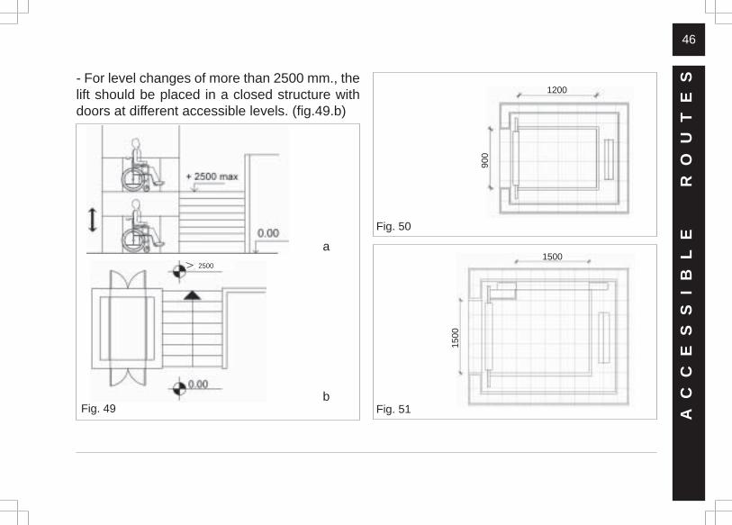
4.9.1 - Lift Size
-The minimum width of the platform lift shouldbe 900 mm. and minimum length should be 1200mm.(fig. 50 and 51)
4.9.2 - Vertical Movement Platform Lifts
- For maximum level change of 2500 mm. verticalmovement platform lifts can be installed. (fig.49a)
46
- For level changes of more than 2500 mm., thelift should be placed in a closed structure withdoors at different accessible levels. (fig.49.b)
AC
CE
SS
IB
LE
RO
UT
ES
Fig. 51
Fig. 50
1500
1500
900
1200
Fig. 49
a
b
2500
47
Fig. 52
Fig. 53 AC
CE
SS
IB
LE
RO
UT
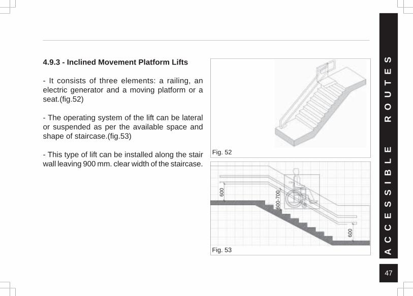
ES4.9.3 - Inclined Movement Platform Lifts
- It consists of three elements: a railing, anelectric generator and a moving platform or aseat.(fig.52)
- The operating system of the lift can be lateralor suspended as per the available space andshape of staircase.(fig.53)
- This type of lift can be installed along the stairwall leaving 900 mm. clear width of the staircase.
600
600-
700
600
48
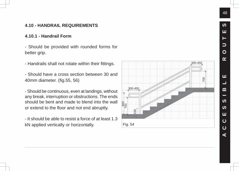
4.10 - HANDRAIL REQUIREMENTS
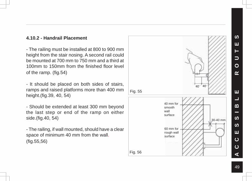
4.10.1 - Handrail Form
- Should be provided with rounded forms forbetter grip.
- Handrails shall not rotate within their fittings.
- Should have a cross section between 30 and40mm diameter. (fig.55, 56)
- Should be continuous, even at landings, withoutany break, interruption or obstructions. The endsshould be bent and made to blend into the wallor extend to the floor and not end abruptly.
- It should be able to resist a force of at least 1.3kN applied vertically or horizontally.
AC
CE
SS
IB
LE
RO
UT
ES
Fig. 5490
070
0
300-450
300-450
700
150
49
AC
CE
SS
IB
LE
RO
UT
ES4.10.2 - Handrail Placement
- The railing must be installed at 800 to 900 mmheight from the stair nosing. A second rail couldbe mounted at 700 mm to 750 mm and a third at100mm to 150mm from the finished floor levelof the ramp. (fig.54)
- It should be placed on both sides of stairs,ramps and raised platforms more than 400 mmheight.(fig.39, 40, 54)
- Should be extended at least 300 mm beyondthe last step or end of the ramp on eitherside.(fig.40, 54)
- The railing, if wall mounted, should have a clearspace of minimum 40 mm from the wall.(fig.55,56)
Fig. 5540 40
Fig. 56
40 mm forsmoothwallsurface
60 mm forrough wallsurface
30-40 mm
50
AC
CE
SS
IB
LE
RO
UT
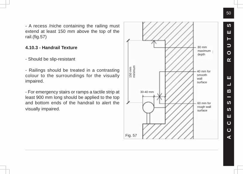
ES- A recess /niche containing the railing must
extend at least 150 mm above the top of therail.(fig.57)
4.10.3 - Handrail Texture
- Should be slip-resistant
- Railings should be treated in a contrastingcolour to the surroundings for the visuallyimpaired.
- For emergency stairs or ramps a tactile strip atleast 900 mm long should be applied to the topand bottom ends of the handrail to alert thevisually impaired.
Fig. 57
40 mm forsmoothwallsurface
60 mm forrough wallsurface
150
mm
min
imum
30-40 mm
80 mmmaximumdepth
51
EN
TR
AN
CE
S05- ENTRANCES
5.1- MANDATORY
- At least one entrance in the facility should haveaccessiblity to the disabled person. In the caseof a new construction, this entrance should bethe main entrance. The position of this entranceand alternate routes should be well markedthrough proper accessiblity signages using theinternational symbol of accessiblity.
- The entrance landing should have a minimumdimension of 1800 mm x 2000 mm. The flooringof this landing should be made conspicuouslydistinct, with tactile rendering, from thesurroundings to guide the visually impaired.
- This entrance should be well connected byaccessible pathways to other accessible
amenities such as parking spaces, both indoorand outdoor, local transit bus-stops and drop-offareas.
- In the case of multi-storied buildings, thisentrance should be connected to an accessibleelevator or ramp.
5.2 - SUGGESTIVE
- A public telephone and benches for waitingmay be installed in the entrance space. This ismandatory if the accessible entrances requireassistance. In such cases the phones mustprovide direct communication with informedpersonnel who can provide assistance.
- The entrance landing should have proper coverfor protection against adverse weatherconditions.
52
Fig. 61
Fig. 58
Fig. 59
06 - DOORS
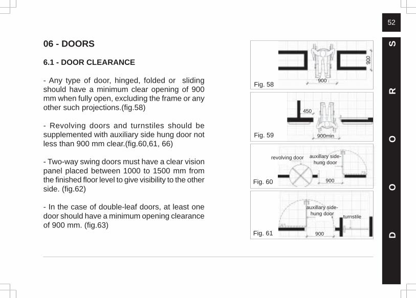
6.1 - DOOR CLEARANCE
- Any type of door, hinged, folded or slidingshould have a minimum clear opening of 900mm when fully open, excluding the frame or anyother such projections.(fig.58)
- Revolving doors and turnstiles should besupplemented with auxiliary side hung door notless than 900 mm clear.(fig.60,61, 66)
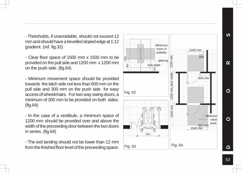
- Two-way swing doors must have a clear visionpanel placed between 1000 to 1500 mm fromthe finished floor level to give visibility to the otherside. (fig.62)
- In the case of double-leaf doors, at least onedoor should have a minimum opening clearanceof 900 mm. (fig.63)
DO
OR
S
900
900
900min
450
900
Fig. 60 900
revolving door auxillary side-hung door
auxillary side-hung door
turnstile
53
Fig. 63
- Thresholds, if unavoidable, should not exceed 12mm and should have a bevelled sloped edge at 1:12gradient. (ref. fig.32)
- Clear floor space of 1500 mm x 1500 mm to beprovided on the pull side and 1200 mm x 1200 mmon the push side. (fig.64)
- Minimum movement space should be providedtowards the latch side not less than 600 mm on thepull side and 300 mm on the push side for easyaccess of wheelchairs. For two-way swing doors, aminimum of 300 mm to be provided on both sides.(fig.64)
- In the case of a vestibule, a minimum space of1200 mm should be provided over and above thewidth of the preceeding door between the two doorsin series. (fig.64)
- The exit landing should not be lower than 12 mmfrom the finished floor level of the preceeding space. D
OO
RS
Fig. 62
1500
800
Minimumzone ofvisibility
glazing
kick-plate
250
900
Fig. 64
1200
min
door
wid
th12
00 m
in15
00 m
in
1500 min
Minimumcleararea.
1200 min
300
600 min
600 min
54
DO
OR
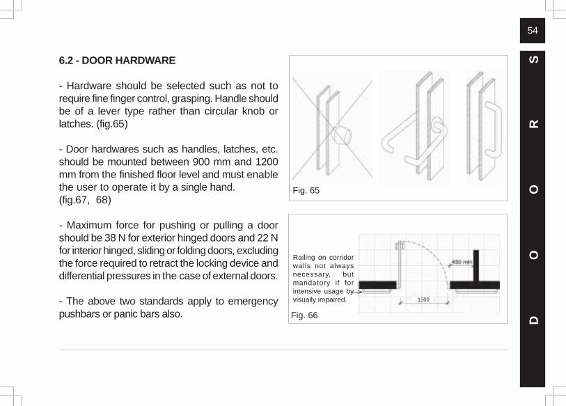
S6.2 - DOOR HARDWARE
- Hardware should be selected such as not torequire fine finger control, grasping. Handle shouldbe of a lever type rather than circular knob orlatches. (fig.65)
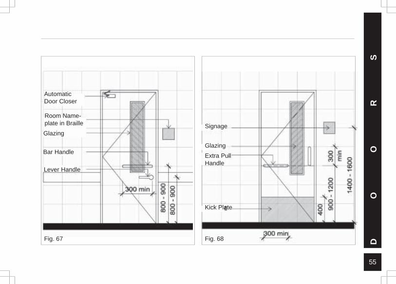
- Door hardwares such as handles, latches, etc.should be mounted between 900 mm and 1200mm from the finished floor level and must enablethe user to operate it by a single hand.(fig.67, 68)
- Maximum force for pushing or pulling a doorshould be 38 N for exterior hinged doors and 22 Nfor interior hinged, sliding or folding doors, excludingthe force required to retract the locking device anddifferential pressures in the case of external doors.
- The above two standards apply to emergencypushbars or panic bars also.
Fig. 65
Fig. 66
Railing on corridorwalls not alwaysnecessary, butmandatory if forintensive usage byvisually impaired. 1500
55
Fig. 68 DO
OR
S
Signage
Glazing
Extra PullHandle
Kick Plate
Fig. 67
AutomaticDoor Closer
Room Name-plate in Braille
Glazing
Bar Handle
Lever Handle
56
Fig. 69
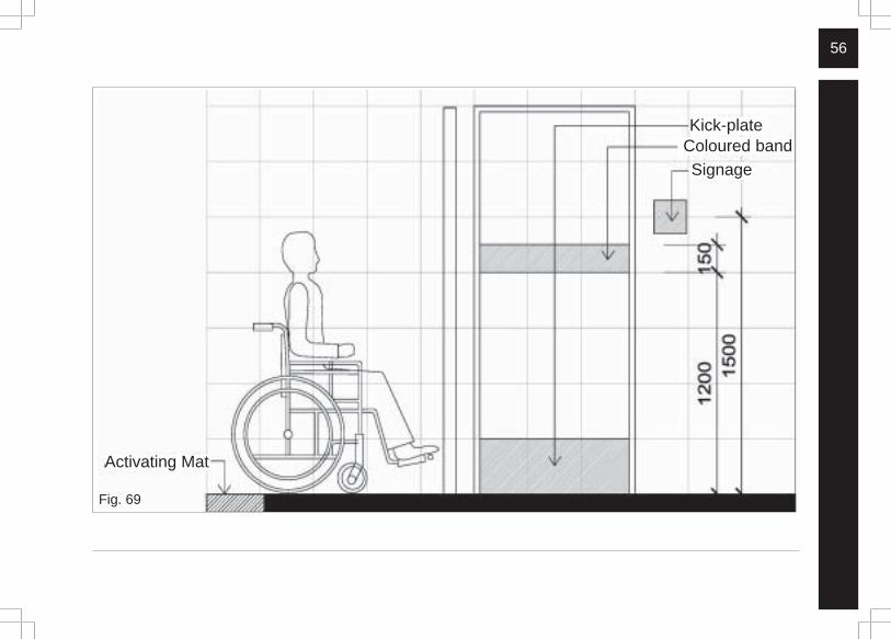
Kick-plateColoured bandSignage
Activating Mat
57
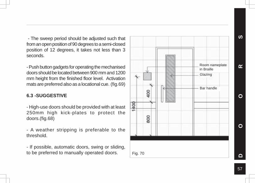
- The sweep period should be adjusted such thatfrom an open position of 90 degrees to a semi-closedposition of 12 degrees, it takes not less than 3seconds.
- Push button gadgets for operating the mechaniseddoors should be located between 900 mm and 1200mm height from the finished floor level. Activationmats are preferred also as a locational cue. (fig.69)
6.3 -SUGGESTIVE
- High-use doors should be provided with at least250mm high kick-plates to protect thedoors.(fig.68)
- A weather stripping is preferable to thethreshold.
- If possible, automatic doors, swing or sliding,to be preferred to manually operated doors.
DO
OR
S
Fig. 70
Room nameplatein Braille
Glazing
Bar handle
58
- Completely glazed doors should be avoided inbuildings frequented by people with visualimpairments. If at all they are installed thenproper protection bars and coloured bandsshould be placed at respective heights.
- An extra pull handle, approximately 300mm inlength should be located 200 to 300mm from theside of the door with the hinges, mountedbetween 900 mm and 1200 mm from the finishedfloor level to facilitate closing the spring mounteddoors locked at 90½.(fig.67, 68)
- Colour and brightness contrast markings noless than 130 mm in width should be appliedhorizontally at a height between 1200 and 1600mm above the floor. (fig.70)
- The door and the frame may be painted in acontrasting colour scheme to the adjoining wallsand the glass itself maybe rendered to facilitateidentification. D
OO
RS
59
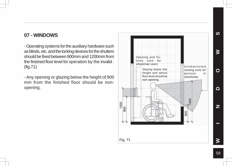
07 - WINDOWS
- Operating systems for the auxiliary hardware suchas blinds, etc. and the locking devices for the shuttersshould be fixed between 900mm and 1200mm fromthe finished floor level for operation by the invalid .(fig.71)
- Any opening or glazing below the height of 900mm from the finished floor should be non-opening.
Fig. 71 WI
ND
OW
S
Opening and fix-tures zone forwheelchair users
Glazing below thisheight and abovefloor level should benon-opening.
Unobs t ruc tedviewing zone forpersons inwheelchair.
60
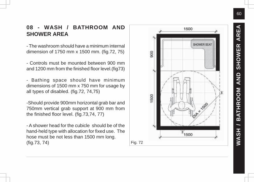
08 - WASH / BATHROOM ANDSHOWER AREA
- The washroom should have a minimum internaldimension of 1750 mm x 1500 mm. (fig.72, 75)
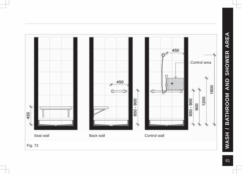
- Controls must be mounted between 900 mmand 1200 mm from the finished floor level.(fig73)
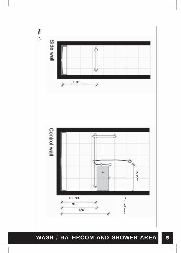
- Bathing space should have minimumdimensions of 1500 mm x 750 mm for usage byall types of disabled. (fig.72, 74,75)
-Should provide 900mm horizontal grab bar and750mm vertical grab support at 900 mm fromthe finished floor level. (fig.73,74, 77)
- A shower head for the cubicle should be of thehand-held type with allocation for fixed use. Thehose must be not less than 1500 mm long.(fig.73, 74) Fig. 72 W
AS
H /
BA
TH
RO
OM
AN
D S
HO
WE
R A
RE
A
61
Fig. 73
Seat wall Back wall Control wall
Control area
WA
SH
/ B
AT
HR
OO
M A
ND
SH
OW
ER
AR
EA
62
Fig. 74
850-900
WASH / BATHROOM AND SHOWER AREA
850-900
900
1200
Control area
685 max
63
WA
SH
/ B
AT
HR
OO
M A
ND
SH
OW
ER
AR
EA
Fig. 75
600max
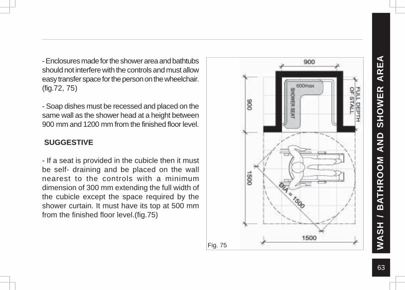
- Enclosures made for the shower area and bathtubsshould not interfere with the controls and must alloweasy transfer space for the person on the wheelchair.(fig.72, 75)
- Soap dishes must be recessed and placed on thesame wall as the shower head at a height between900 mm and 1200 mm from the finished floor level.
SUGGESTIVE
- If a seat is provided in the cubicle then it mustbe self- draining and be placed on the wallnearest to the controls with a minimumdimension of 300 mm extending the full width ofthe cubicle except the space required by theshower curtain. It must have its top at 500 mmfrom the finished floor level.(fig.75)
64
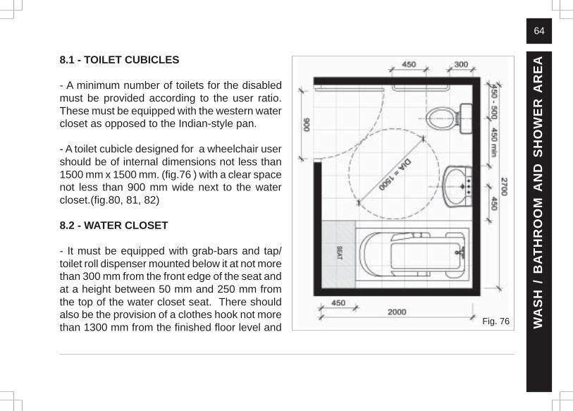
8.1 - TOILET CUBICLES
- A minimum number of toilets for the disabledmust be provided according to the user ratio.These must be equipped with the western watercloset as opposed to the Indian-style pan.
- A toilet cubicle designed for a wheelchair usershould be of internal dimensions not less than1500 mm x 1500 mm. (fig.76 ) with a clear spacenot less than 900 mm wide next to the watercloset.(fig.80, 81, 82)
8.2 - WATER CLOSET
- It must be equipped with grab-bars and tap/toilet roll dispenser mounted below it at not morethan 300 mm from the front edge of the seat andat a height between 50 mm and 250 mm fromthe top of the water closet seat. There shouldalso be the provision of a clothes hook not morethan 1300 mm from the finished floor level and W
AS
H /
BA
TH
RO
OM
AN
D S
HO
WE
R A
RE
A
Fig. 76
65
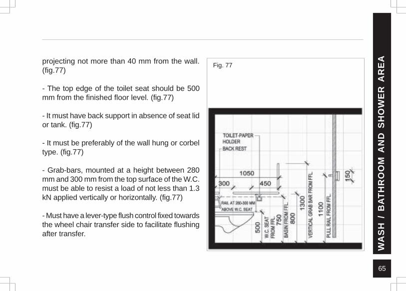
projecting not more than 40 mm from the wall.(fig.77)
- The top edge of the toilet seat should be 500mm from the finished floor level. (fig.77)
- It must have back support in absence of seat lidor tank. (fig.77)
- It must be preferably of the wall hung or corbeltype. (fig.77)
- Grab-bars, mounted at a height between 280mm and 300 mm from the top surface of the W.C.must be able to resist a load of not less than 1.3kN applied vertically or horizontally. (fig.77)
- Must have a lever-type flush control fixed towardsthe wheel chair transfer side to facilitate flushingafter transfer.
Fig. 77
WA
SH
/ B
AT
HR
OO
M A
ND
SH
OW
ER
AR
EA
66
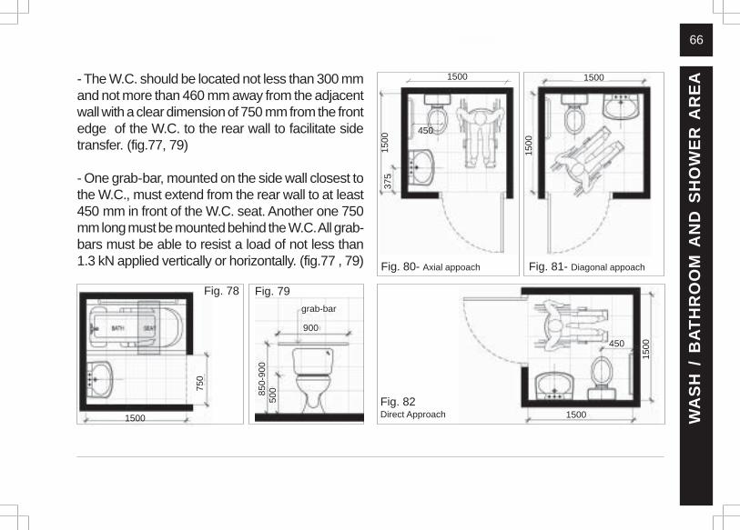
- The W.C. should be located not less than 300 mmand not more than 460 mm away from the adjacentwall with a clear dimension of 750 mm from the frontedge of the W.C. to the rear wall to facilitate sidetransfer. (fig.77, 79)
- One grab-bar, mounted on the side wall closest tothe W.C., must extend from the rear wall to at least450 mm in front of the W.C. seat. Another one 750mm long must be mounted behind the W.C. All grab-bars must be able to resist a load of not less than1.3 kN applied vertically or horizontally. (fig.77 , 79) Fig. 80- Axial appoach Fig. 81- Diagonal appoach
Fig. 82Direct Approach W
AS
H /
BA
TH
RO
OM
AN
D S
HO
WE
R A
RE
A
150
0
7
50
1500
Fig. 78
1500
450
1
500
1500
3
75
1500
1500450
Fig. 79
900
grab-bar
850-
900
500
67
WA
SH
/ B
AT
HR
OO
M A
ND
SH
OW
ER
AR
EA
Fig. 85 Side transfer
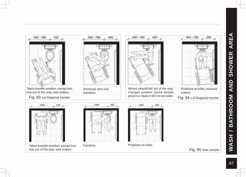
Takes transfer position, swings footrest out of the way, sets brakes.
Removes arm-rest,transfers.
Takes transfer position, swings footrest out of the way, sets brakes.
Moves wheelchair out of the way,changes position (some peoplepivot it or rotate it 90½ to the toilet.
Positions on toilet, releasesbrakes.
Transfers. Positions on toilet.
Fig. 83 a,b-Diagonal transfer Fig. 84 c,d-Diagonal transfer
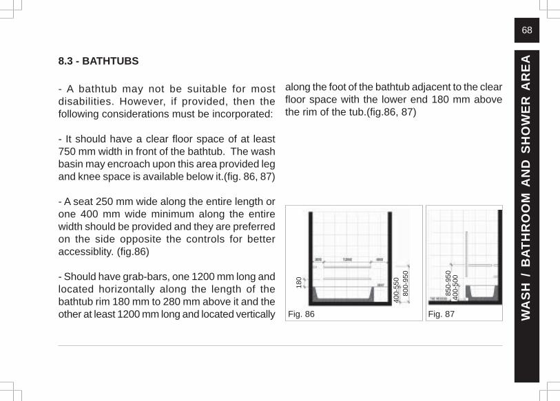
68
8.3 - BATHTUBS
- A bathtub may not be suitable for mostdisabilities. However, if provided, then thefollowing considerations must be incorporated:
- It should have a clear floor space of at least750 mm width in front of the bathtub. The washbasin may encroach upon this area provided legand knee space is available below it.(fig. 86, 87)
- A seat 250 mm wide along the entire length orone 400 mm wide minimum along the entirewidth should be provided and they are preferredon the side opposite the controls for betteraccessiblity. (fig.86)
- Should have grab-bars, one 1200 mm long andlocated horizontally along the length of thebathtub rim 180 mm to 280 mm above it and theother at least 1200 mm long and located vertically Fig. 86 Fig. 87
along the foot of the bathtub adjacent to the clearfloor space with the lower end 180 mm abovethe rim of the tub.(fig.86, 87)
WA
SH
/ B
AT
HR
OO
M A
ND
SH
OW
ER
AR
EA
80
0-95
0
400-
550
180
850
-950
400
-500
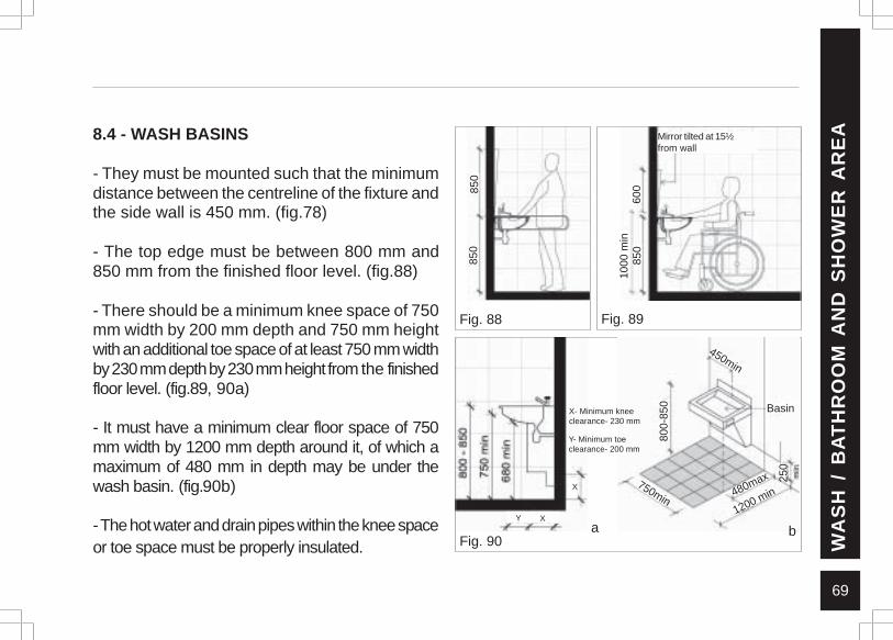
69
8.4 - WASH BASINS
- They must be mounted such that the minimumdistance between the centreline of the fixture andthe side wall is 450 mm. (fig.78)
- The top edge must be between 800 mm and850 mm from the finished floor level. (fig.88)
- There should be a minimum knee space of 750mm width by 200 mm depth and 750 mm heightwith an additional toe space of at least 750 mm widthby 230 mm depth by 230 mm height from the finishedfloor level. (fig.89, 90a)
- It must have a minimum clear floor space of 750mm width by 1200 mm depth around it, of which amaximum of 480 mm in depth may be under thewash basin. (fig.90b)
- The hot water and drain pipes within the knee spaceor toe space must be properly insulated.
Fig. 88 Fig. 89
WA
SH
/ B
AT
HR
OO
M A
ND
SH
OW
ER
AR
EAMirror tilted at 15½
from wall
1000
min
850
600
850
850
Fig. 90a
XY
X
b
800-
850
450min
750min480max 25
0
1200 min
BasinX- Minimum kneeclearance- 230 mm
Y- Minimum toeclearance- 200 mm
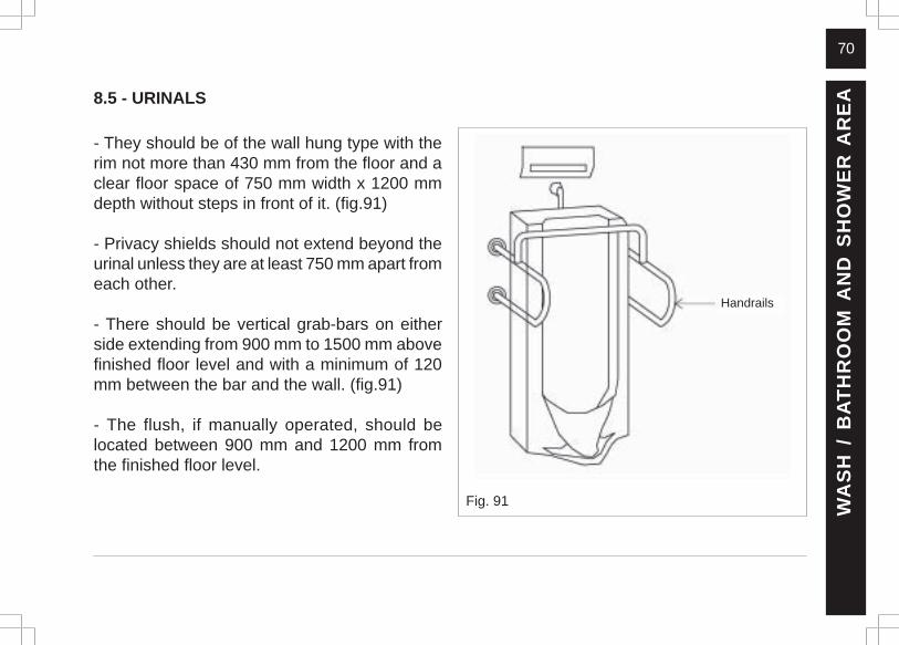
70
8.5 - URINALS
- They should be of the wall hung type with therim not more than 430 mm from the floor and aclear floor space of 750 mm width x 1200 mmdepth without steps in front of it. (fig.91)
- Privacy shields should not extend beyond theurinal unless they are at least 750 mm apart fromeach other.
- There should be vertical grab-bars on eitherside extending from 900 mm to 1500 mm abovefinished floor level and with a minimum of 120mm between the bar and the wall. (fig.91)
- The flush, if manually operated, should belocated between 900 mm and 1200 mm fromthe finished floor level.
WA
SH
/ B
AT
HR
OO
M A
ND
SH
OW
ER
AR
EA
Handrails
Fig. 91
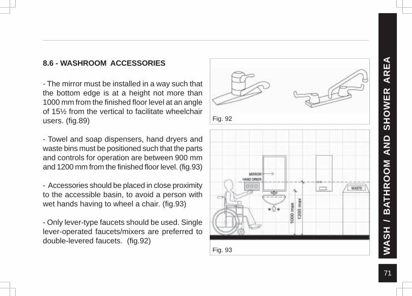
71
8.6 - WASHROOM ACCESSORIES
- The mirror must be installed in a way such thatthe bottom edge is at a height not more than1000 mm from the finished floor level at an angleof 15½ from the vertical to facilitate wheelchairusers. (fig.89)
- Towel and soap dispensers, hand dryers andwaste bins must be positioned such that the partsand controls for operation are between 900 mmand 1200 mm from the finished floor level. (fig.93)
- Accessories should be placed in close proximityto the accessible basin, to avoid a person withwet hands having to wheel a chair. (fig.93)
- Only lever-type faucets should be used. Singlelever-operated faucets/mixers are preferred todouble-levered faucets. (fig.92)
Fig. 93
Fig. 92
WA
SH
/ B
AT
HR
OO
M A
ND
SH
OW
ER
AR
EA
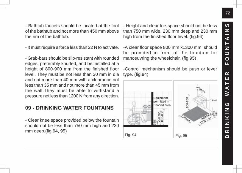
72
- Bathtub faucets should be located at the footof the bathtub and not more than 450 mm abovethe rim of the bathtub.
- It must require a force less than 22 N to activate.
- Grab-bars should be slip-resistant with roundededges, preferably knurled, and be installed at aheight of 800-900 mm from the finished floorlevel. They must be not less than 30 mm in diaand not more than 40 mm with a clearance notless than 35 mm and not more than 45 mm fromthe wall.They must be able to withstand apressure not less than 1200 N from any direction.
09 - DRINKING WATER FOUNTAINS
- Clear knee space provided below the fountainshould not be less than 750 mm high and 230mm deep.(fig.94, 95)
- Height and clear toe-space should not be lessthan 750 mm wide, 230 mm deep and 230 mmhigh from the finished floor level. (fig.94)
-A clear floor space 800 mm x1300 mm shouldbe provided in front of the fountain formanoeuvring the wheelchair. (fig.95)
-Control mechanism should be push or levertype. (fig.94)
Fig. 94 Fig. 95 DR
INK
ING
W
AT
ER
F
OU
NT
AIN
S
800-
850
450min
750min 480max
1200 min
Basin
250
250 75
0 m
in80
0-85
0
Equipmentpermitted inShaded area
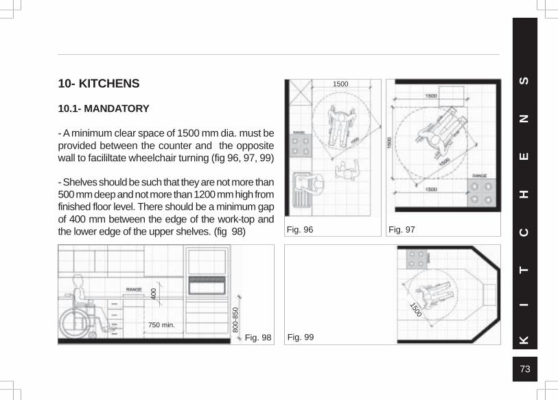
73
10- KITCHENS
10.1- MANDATORY
- A minimum clear space of 1500 mm dia. must beprovided between the counter and the oppositewall to facililtate wheelchair turning (fig 96, 97, 99)
- Shelves should be such that they are not more than500 mm deep and not more than 1200 mm high fromfinished floor level. There should be a minimum gapof 400 mm between the edge of the work-top andthe lower edge of the upper shelves. (fig 98) Fig. 96 Fig. 97
Fig. 98 Fig. 99 KI
TC
HE
NS 1500
1500
80
0-85
0
750 min.
400
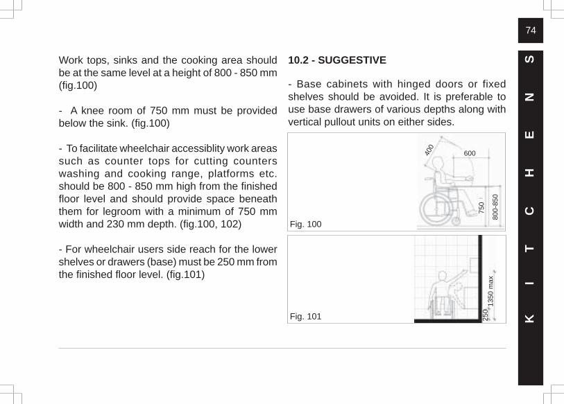
74
Fig. 101
Work tops, sinks and the cooking area shouldbe at the same level at a height of 800 - 850 mm(fig.100)
- A knee room of 750 mm must be providedbelow the sink. (fig.100)
- To facilitate wheelchair accessiblity work areassuch as counter tops for cutting counterswashing and cooking range, platforms etc.should be 800 - 850 mm high from the finishedfloor level and should provide space beneaththem for legroom with a minimum of 750 mmwidth and 230 mm depth. (fig.100, 102)
- For wheelchair users side reach for the lowershelves or drawers (base) must be 250 mm fromthe finished floor level. (fig.101)
Fig. 100
10.2 - SUGGESTIVE
- Base cabinets with hinged doors or fixedshelves should be avoided. It is preferable touse base drawers of various depths along withvertical pullout units on either sides.
KI
TC
HE
NS
250
1350
max
80
0-85
0
750
400
600
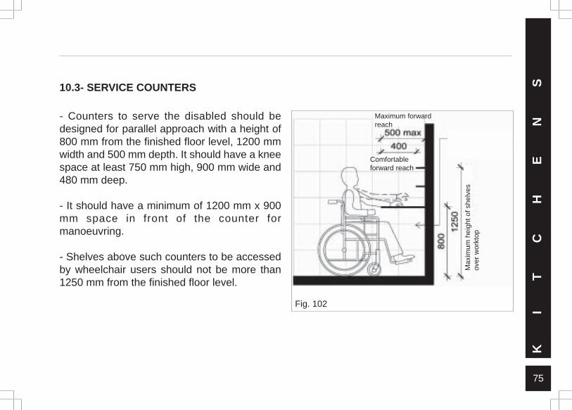
75
10.3- SERVICE COUNTERS
- Counters to serve the disabled should bedesigned for parallel approach with a height of800 mm from the finished floor level, 1200 mmwidth and 500 mm depth. It should have a kneespace at least 750 mm high, 900 mm wide and480 mm deep.
- It should have a minimum of 1200 mm x 900mm space in front of the counter formanoeuvring.
- Shelves above such counters to be accessedby wheelchair users should not be more than1250 mm from the finished floor level.
KI
TC
HE
NS
Clearance to allowpassage of wheelchairarms under worktop
Fig. 102
Max
imum
hei
ght o
f she
lves
over
wor
ktop
Maximum forwardreach
Comfortableforward reach
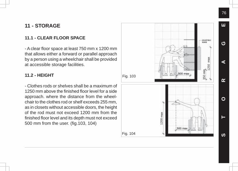
76
11 - STORAGE
11.1 - CLEAR FLOOR SPACE
- A clear floor space at least 750 mm x 1200 mmthat allows either a forward or parallel approachby a person using a wheelchair shall be providedat accessible storage facilities.
11.2 - HEIGHT
- Clothes rods or shelves shall be a maximum of1250 mm above the finished floor level for a sideapproach. where the distance from the wheel-chair to the clothes rod or shelf exceeds 255 mm,as in closets without accessible doors, the heightof the rod must not exceed 1200 mm from thefinished floor level and its depth must not exceed500 mm from the user. (fig.103, 104)
ST
OR
AG
E
Fig. 103
350
1250
Fig. 104
1200
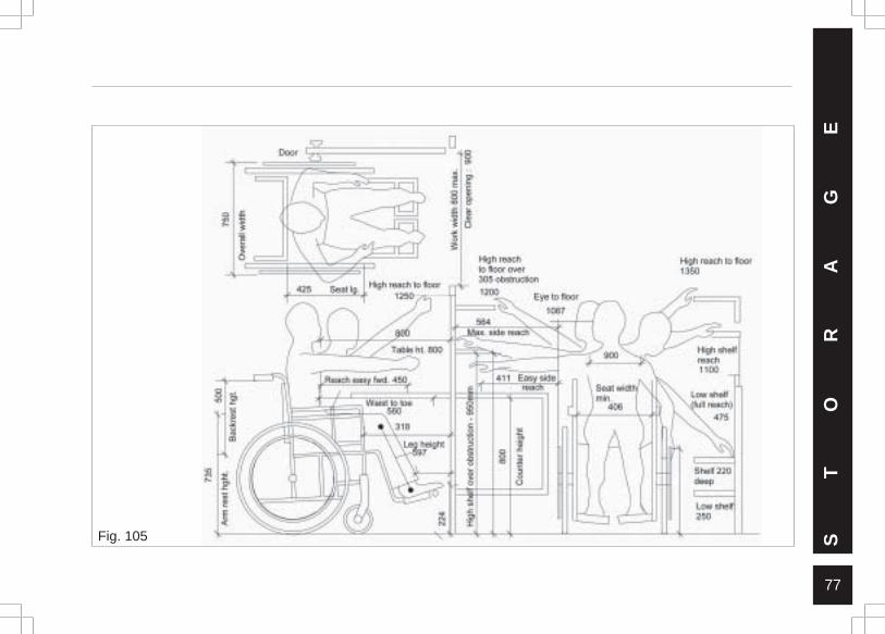
77
ST
OR
AG
E
Fig. 105
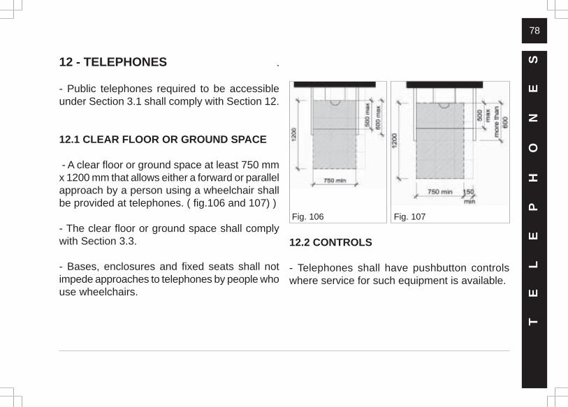
78
Fig. 107Fig. 106
12 - TELEPHONES .
- Public telephones required to be accessibleunder Section 3.1 shall comply with Section 12.
12.1 CLEAR FLOOR OR GROUND SPACE
- A clear floor or ground space at least 750 mmx 1200 mm that allows either a forward or parallelapproach by a person using a wheelchair shallbe provided at telephones. ( fig.106 and 107) )
- The clear floor or ground space shall complywith Section 3.3.
- Bases, enclosures and fixed seats shall notimpede approaches to telephones by people whouse wheelchairs.
TE
LE
PH
ON
ES
12.2 CONTROLS
- Telephones shall have pushbutton controlswhere service for such equipment is available.
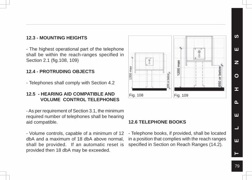
79
Fig. 109Fig. 108
TE
LE
PH
ON
ES12.3 - MOUNTING HEIGHTS
- The highest operational part of the telephoneshall be within the reach-ranges specified inSection 2.1 (fig.108, 109)
12.4 - PROTRUDING OBJECTS
- Telephones shall comply with Section 4.2
12.5 - HEARING AID COMPATIBLE ANDVOLUME CONTROL TELEPHONES
- As per requirement of Section 3.1, the minimumrequired number of telephones shall be hearingaid compatible.
- Volume controls, capable of a minimum of 12dbA and a maximum of 18 dbA above normal,shall be provided. If an automatic reset isprovided then 18 dbA may be exceeded.
12.6 TELEPHONE BOOKS
- Telephone books, if provided, shall be locatedin a position that complies with the reach rangesspecified in Section on Reach Ranges (14.2).
1350
max

80
12.7 CORD LENGTH
- The cord from the telephone to the handsetshall be at least 750 mm long.
12.8 TEXT TELEPHONES
- Text telephones used with a pay telephone shallbe permanently affixed within, or adjacent to, thetelephone enclosure. If an acoustic coupler isused, the telephone cord shall be sufficiently longto allow connection of the text telephone and thetelephone receiver.
- Pay telephones designed to accommodate aportable text telephone shall be equipped with ashelf and an electrical outlet within or adjacentto the telephone enclosure. The telephonehandset shall be capable of being placed flushon the surface of the shelf. The shelf shall becapable of accommodating a text telephone and
shall have (152 mm) minimum vertical clearancein the area where the text telephone is to beplaced.
- Equivalent facilitation may be provided.For example, a portable text telephone may bemade available in a hotel at the registration deskif it is available on a 24-hour basis for use withnearby public pay telephones. In this instance,at least one pay telephone shall comply withparagraph 2 of this Section.
- In addition, if an acoustic coupler is used, thetelephone handset cord shall be sufficiently longso as to allow connection of the text telephoneand the telephone receiver.
- Directional signage shall be provided and shallcomply with Section 01.
TE
LE
PH
ON
ES
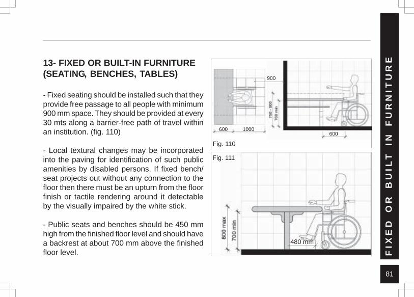
81
13- FIXED OR BUILT-IN FURNITURE(SEATING, BENCHES, TABLES)
- Fixed seating should be installed such that theyprovide free passage to all people with minimum900 mm space. They should be provided at every30 mts along a barrier-free path of travel withinan institution. (fig. 110)
- Local textural changes may be incorporatedinto the paving for identification of such publicamenities by disabled persons. If fixed bench/seat projects out without any connection to thefloor then there must be an upturn from the floorfinish or tactile rendering around it detectableby the visually impaired by the white stick.
- Public seats and benches should be 450 mmhigh from the finished floor level and should havea backrest at about 700 mm above the finishedfloor level. F
IXE
D
OR
B
UIL
T
IN
FU
RN
ITU
RE
Fig. 110
900
1000600600
480 mm
Fig. 111
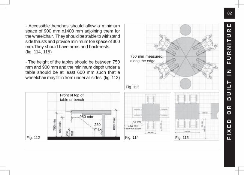
82
- Accessible benches should allow a minimumspace of 900 mm x1400 mm adjoining them forthe wheelchair. They should be stable to withstandside thrusts and provide minimum toe space of 300mm.They should have arms and back-rests.(fig. 114, 115)
- The height of the tables should be between 750mm and 900 mm and the minimum depth under atable should be at least 600 mm such that awheelchair may fit in from under all sides. (fig. 112)
FIX
ED
O
R
BU
ILT
IN
F
UR
NIT
UR
E
Fig. 112 Fig. 114 Fig. 115
Fig. 113
230max
980 min
Front of top oftable or bench
750 min measuredalong the edge
700-800
1400 minspace for access
83
14 - AUTOMATED TELLER MACHINES
- Each automated teller machine required to beaccessible by Section 3.1 shall be on an accessibleroute and shall comply with Section 14
14.1 CLEAR FLOOR SPACE
- The automated teller machine shall be locatedso that clear floor space complying with Section3.3 is provided to allow a person using awheelchair to make a forward approach, aparallel approach, or both, to the machine.
14.2 REACH RANGES
14.2.1 Forward Approach Only
- If only a forward approach is possible, operationalparts of all controls shall be placed within theforward reach range specified in Section 3.3.
14.2.2 Parallel Approach Only
- If only a parallel approach is possible, operationalparts of controls shall be placed as follows:
1. Reach Depth Not More Than 255 mm- Where the reach depth to the operational partsof all controls as measured from the verticalplane perpendicular to the edge of theunobstructed clear floor space at the farthestprotrusion of the automated teller machine orsurround is not more than 255 mm, the maximumheight of the control above the finished floor orgrade shall be 1200 mm.
2. Reach depth More Than 255 mm- Where the reach depth to the operational partsof any control as measured from the verticalplane perpendicular to the edge of theunobstructed clear floor space at the farthestprotrusion of the automated teller machine or
AU
TO
MA
TE
D
TE
LL
ER
M
AC
HIN
ES
84
surround is more than 255 mm, the maximumheight above the finished floor or grade shall beless than 1200 mm.
3. Forward and Parallel Approach- If both forward and parallel approaches arepossible, operational parts of controls shall beplaced within at least one of the reach ranges inparagraphs (1) or (2) of this Section.
4. Bins:- Where bins are provided, for envelopes, wastepaper, or other purposes, at least one of eachtype provided shall comply with the reach rangesand be appropriately marked.
14.3 - CONTROLS
- Controls for user activation shall comply withSection 16.
14.4- EQUIPMENT FOR PERSONS WITH VISION IMPAIRMENTS
- Instructions and all information for use shall bemade accessible to and independently usableby persons with vision impairment.
14.5 - EXCEPTI0N
- Where a function can be performed in asubstantially equivalent manner by using analternative control, only one of the controlsneeded to perform that function is required tocomply with this Section. If the controls areidentified by tactile markings, such markings shallbe provided on both controls.
AU
TO
MA
TE
D
TE
LL
ER
M
AC
HIN
ES
85
AL
AR
MS15 - ALARMS .
15.1 LOCATION
- At a minimum, visual signal appliances shallbe provided in buildings and facilities in each ofthe following areas: rest-rooms and any othergeneral use areas (e.g. meeting rooms),hallways, lobbies, and any other area forcommon use.
15.2 AUDIBLE ALARMS
- If provided, audible emergency alarms shallproduce a sound that exceeds the prevailingequivalent sound level in the room or space byat least 15 dbA or exceeds any maximum soundlevel with a duration of 60 seconds by 5 dbA,whichever is louder.
- Sound levels for alarm signals shall not exceed120 dbA.
15.3 VISUAL ALARMS
- Visual alarm signal appliances shall beintegrated into the building or facility alarmsystem. If single station audible alarms areprovided then single station visual alarm signalsshall be provided.
- Visual alarm signals shall have the followingminimum photometric and location features:
- 1.The lamp shall be a xenon strobe type or equivalent.- 2.The colour shall be clear or nominal white (i.e.unfiltered or clear filtered white light)- 3. The maximum pulse duration shall be two-tenths of one second [0.2 sec] with a maximumduty cycle of 40 per cent. The pulse duration isdefined as the time interval between initial andfinal points of 10 per cent of maximum signal.- 4.The intensity shall be a minimum of 75candelas.
86
AL
AR
MS- 5. The flash rate shall be a minimum of 1 Hz
and a maximum of 3 Hz.- 6. The appliance shall be placed 2000 mmabove the highest floor level within the space,or 150 mm below the ceiling, whichever is lower.- 7. In general, no place in any room or spacerequired to have a visual signal appliance shallbe more than 15 mts from the signal [in horizontalplane]. In large rooms and spaces exceeding 30mts across, without obstructions 2 mts abovethe finished floor level, such as auditoriums,devices may be placed around the perimeter,spaced a maximum 30 mts apart, in lieu ofsuspending appliances from the ceiling.- 8. No place in common corridors or hallways inwhich visual alarm signalling appliances arerequired shall be more than 15 mts from thesignal.
15.4 AUXILIARY ALARMS
- Units and sleeping accommodations shall havea visual alarm connected to the buildingemergency alarm system or shall have astandard 110-volt electrical receptacle into whichsuch an alarm can be connected and a meansby which a signal from the building emergencyalarm system can trigger such an auxiliary alarm.When visual alarms are in place, the signal shallbe visible in all areas of the unit or room.Instructions for use of the auxiliary alarm orreceptacle shall be provided.
87
CO
NT
RO
LS
AN
D O
PE
RA
TIN
G M
EC
HA
NIS
MS16 - CONTROLS AND OPERATING
MECHANISMS .
- Controls and operating mechanisms requiredto be accessible under Section 3.1 shall complywith the following:
16.1 CLEAR FLOOR SPACE
- Clear floor space complying with Section 3.3that allows a forward or a parallel approach by aperson using a wheelchair shall be provided atcontrols, dispensers, receptacles, and otheroperational equipments.
16.2 HEIGHT
- The highest operational part of controls,dispensers, receptacles, and other such operableequipment shall be placed within at least one ofthe reach ranges specified in Section 3.2. (fig.116)
- Electrical and communications systemreceptacles on walls shall be mounted no lessthan 380 mm above the floor level.
16.3 OPERATION
- Controls and operating mechanisms shall beoperational with one hand and shall not requiretight grasping, pinching or twisting of the wrist.The force required to activate controls shall beno greater than 22.2 N.
16.4 - EXCEPTION
- These requirements do not apply where theuse of special equipments dictates otherwise orwhere electrical and communications systemsreceptacles are not normally intended for useby building occupants.
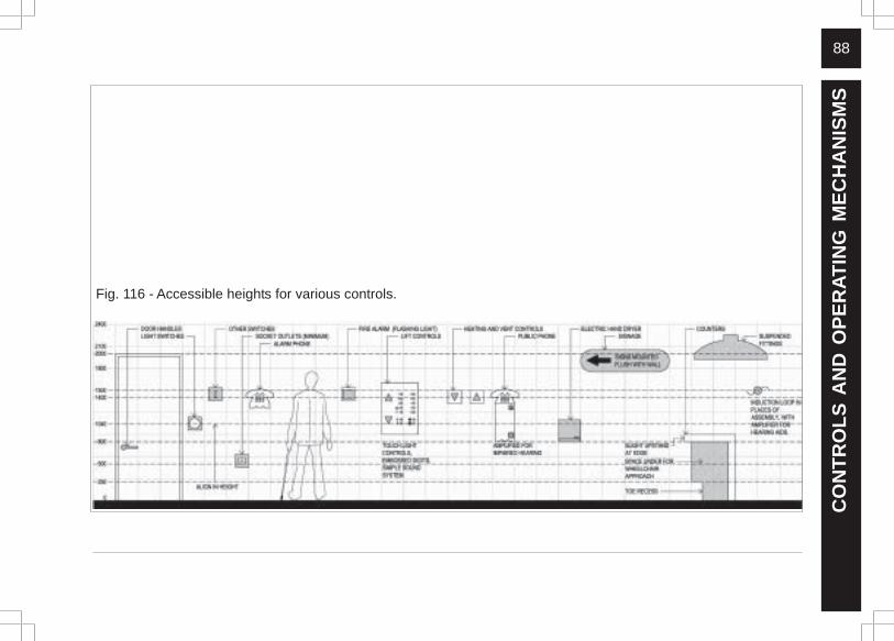
88
CO
NT
RO
LS
AN
D O
PE
RA
TIN
G M
EC
HA
NIS
MS
Fig. 116 - Accessible heights for various controls.
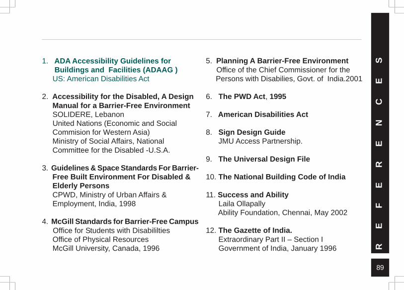
89
RE
FE
RE
NC
ES1. ADA Accessibility Guidelines for
Buildings and Facilities (ADAAG ) US: American Disabilities Act
2. Accessibility for the Disabled, A Design Manual for a Barrier-Free Environment SOLIDERE, Lebanon United Nations (Economic and Social Commision for Western Asia) Ministry of Social Affairs, National Committee for the Disabled -U.S.A.
3. Guidelines & Space Standards For Barrier- Free Built Environment For Disabled & Elderly Persons CPWD, Ministry of Urban Affairs & Employment, India, 1998
4. McGill Standards for Barrier-Free Campus Office for Students with Disabililties Office of Physical Resources McGill University, Canada, 1996
5. Planning A Barrier-Free Environment Office of the Chief Commissioner for the Persons with Disabilies, Govt. of India.2001
6. The PWD Act, 1995
7. American Disabilities Act
8. Sign Design Guide JMU Access Partnership.
9. The Universal Design File
10. The National Building Code of India
11. Success and Ability Laila Ollapally Ability Foundation, Chennai, May 2002
12. The Gazette of India. Extraordinary Part II – Section I Government of India, January 1996

90
AB
OU
T
TH
E
OR
GA
NIS
AT
ION
SHandicap International (HI)
An international non-government organisation,it has been present in India since 1988. HI worksto support actions towards an inclusive, barrier-free and rights-based society for persons withdisabilities and other vulnerable persons in India.To this end HI works with people, local andinternational organisations and Governmentswhich share the vision of an inclusive societywhere vulnerable people have equal rights andopportunities and live their lives with dignity,experience joy as well as a sense of fulfilment,irrespective of the cause, nature and theenvironment underlying the situation. People areunderstood to include persons with disabilitiesand other persons in situations of vulnerability,their families and their communities, irrespectiveof religion, caste or creed.
Environmental PlanningCollaborative
Established in Ahmedabad in 1996, it is a non-profitprofessional planning and developmentmanagement company that undertakes research,advocacy, capacity building and professionalconsultancy services. EPC works primarily withurban local bodies and a variety of other agenciesinvolved in planning and development, such as stategovernment departments, international funding andlending agencies, and non-governmentalorganizations (NGOs). Its work spans a wide rangeof developmental issues including urban planning,urban design, urban management, regional andenvironmental planning, urban transport, heritageconservation, development regulations, disastermanagement and natural resources management.Its projects are undertaken in a collaborative mannerwith significant involvement from the client and otherrelated agencies.
91
AB
OU
T
TH
E
OR
GA
NIS
AT
ION
SHCP Design and ProjectManagement Pvt. Ltd.
A design and management company inAhmedabad, it was established in 1961. Previouslyknown as Messrs. Hasmukh C. Patel, Architectsand Planners, HCPDPM has extensive experiencein architectural design, construction management,interior design and urban design, with projectsincluding educational campuses, institutionalbuildings, townships, recreational buildings andfactories. Its design philosophy has a basicinsistence on clarity and simplicity in design, andits projects have drawn consistently from thismodernist and functional aesthetic. With focusremaining squarely on architecture and urbandesign, the firm frequently extends its concernthrough partnering with the Environmental PlanningCollaborative (EPC), a planning and developmentmanagement company; and TDW Pvt. Ltd., afurniture design/manufacturing firm.
Mind’s Eye Design
A design, engineering and architecturalconsultancy, started in 1988, it is among the fewsuch integrated consultancies in the country. Itsdesign process integrates aesthetics withtechnology, material science, ergonomics, valueengineering, cultural aspects, production detailsand final implementation. This holistic approach toall design solutions is the backbone of itsphilosophy. It has been involved in product design,signage design, corporate identity and graphicsdesign, space and exhibition design and designfor special needs such as of children, old peopleand the less abled. It is also involved in academialike the National Institute of Design (NID), MudraInstitute of Communcation (MICA), NationalInstitute of Fashion Technology (NIFT), ShrishtiSchool of Design (Bangalore) and the School ofInterior Design (SID).

92
AB
OU
T
TH
E
OR
GA
NIS
AT
ION
SVastu Shilpa FoundationFor Studies and Researchin Environmental Design
A non-profit, non-Government public charitabletrust in Ahmedabad, it was established in 1978.Research, Research Application andDemonstration being the tri-fold activities, it hasbeen involved in pioneering research to evolveindigenous design norms and planningstandards which are rooted to the socio-culturalmilieu as well as appropriate to its resource base.Settlement design, heritage conservation,sustainable built environment, appropriatetechnology, design theories are some of theareas of its concern. Vastu Shilpa Foundation,as a bridge between academics and practice,has realized large-scale housing, urban designand city planning projects, and has brought outa number of publications based on its first-handresearch.
UNNATI - Organisation forDevelopment Education
A voluntary non-profit organisation, it wasregistered under the Societies Registration Act(1860) in 1990. Currently, we are engaged inproviding strategic issue-based support todevelopment initiatives in Gujarat and Rajasthan.The primary aim is to promote social inclusion anddemocratic governance so that the vulnerablesections of our society are empowered toeffectively participate in the mainstreamdevelopment and decision-making processes.The above aim is accomplished throughundertaking collaborative research, publiceducation, advocacy, direct field-level mobilisationand implementation with multiple stakeholders.While we work at the grassroot level to policy levelenvironment for ensuring basic rights of citizens,we derive inspiration from the struggles of thevulnerable and strength from the partners.

93
PARITOSH, Usmanpura, Ahmedabad -380013, IndiaPhone: (079) 27550102, 27553069Fax: 27550649, 27552924Web: www.epconnet.com, E-mail: [email protected]
Rupdip, 39, Sudarshan Society, Part-II, Naranpura,Ahmedabad - 380013, IndiaPhone: (079) 55425646, Email: [email protected]
PARITOSH, Usmanpura, Ahmedabad -380013, IndiaPhone: (079) 27550875, 27552563, 27552442Fax: 27552924Web: www.hcponnet.com, E-mail: [email protected]
No. 703 H. K. House, Ashram Road Ahmedabad 380 009,India Tel: +91-79 - 26581467; Mob : +91-9824021607
G -1 / 200, Azad Society, Ahmedabad - 380 015, IndiaPhone: (079) 26746145, 26733296Email: [email protected]
SANGATH, Near Drive-In Cinema, Thaltej, Ahmedabad,380054, IndiaPhone : (079) 27451555 Fax : 27452006Web: www.vastushilpa.org, E-mail : [email protected]
Environmental Planning Collaborative (EPC)
Handicap International
HCP Design and Project Management
MIND’S EYE DESIGN Private Limited
UNNATI - Organisation for Development Education
Vastu Shilpa Foundation for Studies and Researchin Environmental Design,
CO
NT
AC
T
DE
TA
IL
S
94
AP
PE
ND
IXAPPENDIX
STATUTORY AND REGULATORY PROVISIONS
Legislation
CH. VIII - NON-DISCRIMINATION
CH. V. EDUCATION
REGULATIONS – A BRIEF
1) National Building Code of India, 19832) The Guidelines and Space Standards for a Barrier-Free Built Environment for Disabled and Elderly Persons (CPWD)3) Ahmedabad General Development Control Regulations4) Delhi Building Access By-laws
95
AP
PE
ND
IXSTATUTORY AND REGULATORY
PROVISIONS
There are various statutory and regulatoryprovisions that encourage and promoteincorporation of barrier-free features in publicspaces, facilities and services. Relevant portionsfrom a few of them are given below:
LEGISLATION
The Persons With Disabilities (EqualOpportunities, Protection of Rights and FullParticipation) Act, 1995 – also known as the PWDAct 1995.
This Act, passed by the Indian Parliament in Janu-ary 1996, seeks to protect the rights of personswith disabilities and provide them equal opportu-nities in various spheres. Some of the clauseswhich refer to accessibility are given here -
CH. VIII - NON-DISCRIMINATION
44. Establishments in the transport sector shall,within the limits of their economic capacity anddevelopment for the benefit of persons with dis-abilities, take special measures to-
a. adapt rail compartments, buses, vesselsand aircraft in such a way as to permiteasy access to such persons;
b. adapt toilets in rail compartments,vessels, aircraft and waiting rooms in sucha way as to permit the wheelchair usersto use them conveniently.
45. The appropriate Governments and the localauthorities shall, within the limits of their eco-nomic capacity and development, provide for -
96
AP
PE
ND
IXa. installation of auditory signals at red lights
in the public roads for the benefit ofpersons with visual handicap;
b. causing curb cuts and slopes to be madein pavements for the easy access ofwheelchair users;
c. engraving on the surface of the zebracrossing for the blind or for persons withlow vision;
d. engraving on the edges of railwayplatforms for the blind or for persons withlow vision;
e. devising appropriate symbols of disability;f. warning signals at appropriate places.
46. The appropriate Governments and the localauthorities shall, within the limits of their eco-nomic capacity and development, provide for -
a. ramps in public buildingsb. adaptation of toilets for wheelchair users
c. Braille symbols and auditory signals inelevators or lifts
d. ramps in hospitals, primary health centresand other medical care and rehabilitationinstitutions.
CH. V. EDUCATION
30. Without prejudice to the foregoing provisions,the appropriate Governments shall by notifica-tion prepare a comprehensive education schemewhich shall make provision for
(b) the removal of architectural barriers fromschools, colleges or other institutions impartingvocational and professional training;
Source: The above summary is based on the full PWD Act,1995 as well as The Gazette of India, Extraordinary Part II– Section I, published by Authority, New Delhi, Monday,January 1, 1996 / Pausa 11, 1917 – Ministry of Law, Justiceand Company Affairs (Legislative Department).
97
AP
PE
ND
IXREGULATIONS – A BRIEF
Provisions and regulations for providing featuresof accessibility for people with disabilities areguided by two items of national regulations: theNational Building Code of India and the IS: 4963- 1968: Recommendations for Buildings andFacilities for the Physically Handicapped.
1) National Building Code of India, 1983
Revised in 2003, Part III (Clause 12.21),Appendix E - Special Requirements for Planningof Public Buildings Meant for Use of PhysicallyHandicapped issued by the Bureau of IndianStandards. These provide design standards forsite planning and development for variousaspects, including walks and parking lots, designof building components like ramps, entrances,doors and doorways, stairs, floors, toilet rooms,designing for children, etc. The National Building
Code also includes a list of several standards,which are acceptable as ‘good practice’, and‘accepted standards’ in the context of the NBC.These may be used by Development Authoritiesas a guide in conformity with the requirementsof the referred Clauses in the Code. Significantamong these is the IS: 4963 - 1968:Recommendations for Buildings and Facilitiesfor the Physically Handicapped.
However, these regulations provide guidelinesfor adoption of building by-laws in different Statesand are not made mandatory across the country.Most cities that have barrier-free regulationshave based them on these standards.
98
2) The Guidelines and Space Standards for Barrier Free Built Environment for Disabled and Elderly Persons (CPWD)
These are issued by the CPWD, Ministry ofUrban Affairs and Employment: These provideguidelines for location and placement of controlsand their height and range of comfortable reach,location of facilities like counters, telephonebooths, water fountains, mailboxes, vendingmachines, road crossing and taxi stand designs.Minimum access provisions required in varioustypes of buildings (these cover single detached,single dwelling units, staff housing, multipledwelling and high rise residential units andtenements, tenement houses, row houses,apartments and town houses, post offices, banksand financial service institutions, shop-housesand single-storey, places of worship, foodcentres, community centres, village halls,auditoria, concert halls, assembly halls, cinemas,theatres and other places of public assembly).
3) Ahmedabad General Development Control Regulations
In Ahmedabad, the disability regulations aredefined within Chapter 28 “To Provide Facilitiesfor Physically Handicapped Persons” of theGeneral Development Control Regulations.These include regulations for site planning anddevelopment like parking and access as well asregulations for building design for elements likestaircases, ramps, doors and windows, toilets, etc.
4) Delhi Building Access By-laws
The Ministry of Urban Development and PovertyAlleviation has issued a public notice proposingamendments to the Unified Building By-laws,1983, pertaining to the National Capital Territoryof Delhi, with a view to providing a barrier-freeenvironment in public buildings for persons withdisability and are applicable to all buildings,
AP
PE
ND
IX
99
AP
PE
ND
IXrecreational areas and facilities used by the
public (domestic residences are exempt).
It seeks to identify the disabilities which includeimpairments that cause individuals to usewheelchairs; impairments that cause individualsto walk with difficulty or insecurity; individualsusing braces or crutches, amputees, arthritics,spastics and those with pulmonary and cardiacills; such hearing disabilities that might make anindividual insecure in public areas because heis unable to communicate or hear warningsignals; as well as sight disabilities. It specifiesthat every public building should have at leastone access to main entrance/exit to the disabled,which shall be indicated by proper signage. Thisentrance shall be approached through a properramp together with stepped entry. Access pathfrom the plot entry and surface parking to buildingentrance will have even surface without any step.Slope, if any shall not have gradient greater than
5 percent and use of appropriate floor materialto guide visually impaired persons.
For parking of vehicles of disabled persons,surface parking for two equivalent car spacesshall be provided near the entrance for thephysically challenged persons with maximumtravel distance of three metres from buildingentrance. It takes care of specified facilities suchas approach to plinth level, corridor connectingthe entrance/exit for the handicapped, stairways,lift, toilet and drinking water. While Braille signageshall be provided at the above-specified facilities,the notice also calls for provision of ramps withnon-slip material at the entry to the building.
Guiding floor materials or devices that emit soundshall be provided to guide the visually impairedpersons in the corridor connecting the entranceand exit for the handicapped. Stairways withopen riser and provision of nosing are not
100
permitted in such buildings. Wherever lift isrequired as per by-laws, provision of at least onelift shall be made for the wheelchair user withspecified cage dimensions and Braille signage.It provides for one special WC in a set of toilet tobe provided for the use of the handicapped.
An alternative to immediate evacuation of abuilding via staircases and/or lifts is themovement of persons with disability to safetyareas within a building. If possible, they couldremain there until fire is controlled orextinguished or until rescued by fire-fighters. Itis useful to have the provision of a refugee area,usually at the fire protected stair- landing on eachfloor that can safely hold one or two wheelchairs.
Note: Many other states, union territories andcity development authorities have provisions andby-laws similar to above.
AP
PE
ND
IX
101
PA
RT
NE
RS
IN
T
HE
M
OV
EM
EN
T
Individuals
Ashkha Naik, Amit Sheth, Anagha Muzumdar,Anand Patel, Archana Shrivastav, Arindam Mitra,Arpit Dutt, Aruna Khasgiwala, B R Balachandran,Balkrishna Doshi, Bhushan Punani, Bimal Patel,Bindu Nair, Binoy Acharya, BrinthalakshmiSubramanian, D Nanda, Deepa Sonpal, DilipMehta, Geeta Sharma, Govind Kerai, HasmukhPatel, Jyotish Chowdhary, Kamal Mangaldas,Kanchan Patel, Kahan Vyas, Karan Grover,Kinnari Desai, Lalit Baveja, M M Patel, MaheshDayalan, Meghna Patel, Members of the Media,Mitul Shukla, Nandini Rawal, Narendra Amin,Nimish Patel, O Ravi, Prabha Mehta, PradeepMakhijani, Praveen Nahar, Raajesh Moothan,Rohit Patel, S Balaram, Sanjay Dave,Shankharupa Damle, Sushma Oza, SwetaBhayut, Uday Shelat, Vishnuprasad Raval, VijayMatai, Vijay Patel, Yatin Pandya
Institutions
Abhikram / Panika, Ahmedabad MunicipalCorporat ion, Ahmedabad Study Act ionGroup, Blind People’s Association, Centrefor Environmental Planning and Technology,Charkha, Commissioner of Disabil i t ies-Gujarat, Department of Architecture-M.S.Univers i ty, DISHA, Eklavya Educat ionFoundat ion , Env i ronmenta l P lann ingCollaborative, Faculty of Social Work-M.S.University, Handicap International, HCPDesign and Project Management Pvt. Ltd,ICICI Bank, Mind’s Eye Design, NationalInstitute of Design, Parakh, Planet Health,Shri Navchetan Blind Men’s Association,Shri Yuva Viklang Mandal, United Way ofBaroda, UNNATI -Organ isa t ion fo rDevelopment Educat ion, Vastu Shi lpaFoundation
P A R T N E R S I N A C C E S S I B I L I T Y M O V E M E N T
102N O T E S