Embed Size (px)
Citation preview
RRA for Proposed LPG Bottling Plant of 3 X 300 MT Mounded Storage atBarkani Village, Balangir- Odisha.
ABC Techno Labs India Pvt. Ltd. Page 1
Rapid Risk AssessmentReport for new LPG BottlingPlant near Balangir, OdishaBharat Petroleum Corporation Limited
Submitted by Prepared by
atPlot no: 12, Khata No: 109 & 111,
Rev Plot No: 93(p), 902(p),IDCO Growth Centre Ph- II,
Barkani Village, Balangir District, Odisha.
RRA for Proposed LPG Bottling Plant of 3 X 300 MT Mounded Storage atBarkani Village, Balangir- Odisha.
ABC Techno Labs India Pvt. Ltd. Page 2
PROJECT DETAILSName ofPublication
Rapid Risk Assessment Report for new LPG Bottling Plant nearBalangir, Odisha
Project Number Version 2 Released May 2017CONTACT DETAILSABC Techno Labs India Pvt Ltd.#400, 13th Street,SIDCO Industrial Estate (North Phase)Ambattur – 600 098Land Mark: Near National Productivity CouncilPh: +91-44-2616 1123 / 24 / 25.Fax: +91-44-2616 3456E-mail: [email protected] Techno Labs has used information provided to it by the Client and governmental registers,databases, departments and agencies in the preparation of this report. ABC Techno Labs doesnot know, nor does it have any reason to suspect, that the information provided to it was false,inaccurate, incomplete or misleading at the time of its receipt. This report is supplied on thebasis that while ABC Techno Labs believes all the information in it is deemed reliable at thetime of publication, it does not warrant its accuracy or completeness and to the full extentallowed by law excludes liability in contract or otherwise, for any loss or damage sustained byany person or body corporate arising from or in connection with the supply or use of the wholeor any part of the information in this report through any cause whatsoever.
ABC Techno Labs also believes that the facts presented in this report are accurate as on date itwas written. However, it is impossible to dismiss absolutely, the possibility of errors oromissions. ABC Techno Labs therefore, specifically disclaim any liability resulting from the useor application of the information contained in this report. The information is not intended toserve as legal advice related to the individual section.
RRA for Proposed LPG Bottling Plant of 3 X 300 MT Mounded Storage atBarkani Village, Balangir- Odisha.
ABC Techno Labs India Pvt. Ltd. Page 3
CONTENTS
CHAPTER 1: INTRODUCTION ...................................................................................................................................... 7
1.1 Preamble................................................................................................................................................................. 71.2 Scope for RRA As Specified By BPCL ....................................................................................................................... 71.3 Objectives of RRA .................................................................................................................................................... 91.4 Approach & Methodology for Risk Assessment ...................................................................................................... 91.5 Format of RRA Report ............................................................................................................................................11
CHAPTER 2: PROJECT DESCRIPTION ........................................................................................................................ 14
2.1 Introduction...........................................................................................................................................................142.2 Project Location .....................................................................................................................................................142.3 Infrastructure ........................................................................................................................................................142.3.1 Compound Wall, Gates and Fencing .......................................................................................................................142.3.2 Kerb Wall Fencing..................................................................................................................................................142.3.3 Storage Vessel ........................................................................................................................................................142.3.4 Filling Cum Empty Cylinder Shed...........................................................................................................................152.3.5 LPG Filling Facility .................................................................................................................................................152.3.6 Filled Cylinder Storage Shed ..................................................................................................................................152.3.7 Inhouse Pressure Testing Facility..........................................................................................................................162.3.8 Chain Conveyor System..........................................................................................................................................162.3.9 Electronic Carousel ................................................................................................................................................172.3.10 LPG Pump / Compressor Shed ...............................................................................................................................172.3.11 Admin. / Amenity Building / Planning Room ........................................................................................................172.3.12 Security Cabin ........................................................................................................................................................172.3.13 Engineering/Consumables Stores..........................................................................................................................172.3.14 MCC & HT Room .....................................................................................................................................................182.3.15 DG Set Shed ............................................................................................................................................................182.3.16 HT Room ................................................................................................................................................................182.3.17 Cycle /Car Shed ......................................................................................................................................................182.3.18 Inspection Platform ...............................................................................................................................................182.3.19 Weighbridge ..........................................................................................................................................................182.3.20 Tank Lorry Gantry .................................................................................................................................................182.3.21 Truck Parking Area/Drainage System...................................................................................................................192.3.22 PCVO Crew Rest Room/Barrier Gate......................................................................................................................192.3.23 Fire Protection Facilities........................................................................................................................................192.3.24 Gas Monitoring System ..........................................................................................................................................202.3.25 Air Compressor / Receiver / Dryer........................................................................................................................202.3.26 Electrical System....................................................................................................................................................202.3.27 Transformer ..........................................................................................................................................................202.3.28 Maximum Demand .................................................................................................................................................202.3.29 Electrical Fittings ...................................................................................................................................................212.3.30 Main Instrument Control Panel (MIC)....................................................................................................................212.3.31 Bore Well ...............................................................................................................................................................212.3.32 Roads .....................................................................................................................................................................212.3.33 Plant Security System ............................................................................................................................................212.3.34 Vapour Seal ............................................................................................................................................................212.3.35 Communication System .........................................................................................................................................222.4 Process Parameters & Design Basis.......................................................................................................................222.5 Filling/Testing Equipments ...................................................................................................................................232.6 Safety Philosophy...................................................................................................................................................242.6.1 LPG Installations - Codes & Standards ...................................................................................................................242.6.2 Mounded Storage for LPG ......................................................................................................................................252.7 Physical Properties of LPG .....................................................................................................................................252.8 Meteorological Data...............................................................................................................................................262.8.1 Meteorological Conditions in Project Area ............................................................................................................262.8.2 Meteorological Data Considered for the Study ......................................................................................................27
CHAPTER 3: HAZARD ANALYSIS ............................................................................................................................... 30
3.1 Introduction...........................................................................................................................................................303.2 Risk Assessment and Hazard Identification ..........................................................................................................303.3 Liquefied Petroleum Gas (LPG)..............................................................................................................................313.4 Hazards from LPG Storage and Handling ...............................................................................................................323.4.1 Jet Fire....................................................................................................................................................................323.4.2 Vapour Cloud Explosion.........................................................................................................................................323.4.3 Flash Fire ...............................................................................................................................................................323.5 Hazardous Conditions Due To Release of LPG .......................................................................................................32
RRA for Proposed LPG Bottling Plant of 3 X 300 MT Mounded Storage atBarkani Village, Balangir- Odisha.
ABC Techno Labs India Pvt. Ltd. Page 4
3.5.1 Thermal Effects ......................................................................................................................................................323.5.2 Delayed Ignition and Explosion .............................................................................................................................333.6 Identification of Hazard for LPG Unloading, Storage and Bottling Facilities .........................................................333.6.1 Categories of Hazards ............................................................................................................................................333.6.2 Hazard Identification (HAZID)...............................................................................................................................333.6.3 Release and Outcome Scenarios ............................................................................................................................34
CHAPTER 4: HAZARD & OPERABILITY (HAZOP) STUDY .......................................................................................... 39
4.1 HAZOP Study for Mounded Storage of LPG ............................................................................................................394.2 Methodology for HAZOP Study...............................................................................................................................394.3 Undertaking the Study ...........................................................................................................................................404.4 Facilities Considered For HAZOP Study .................................................................................................................404.5 HAZOP Worksheets................................................................................................................................................40
CHAPTER 5: CONSEQUENCE ANALYSIS ..................................................................................................................... 51
5.1 Preamble................................................................................................................................................................515.2 Selected Scenarios for Consequence Analysis .......................................................................................................515.3 Consequence Analysis............................................................................................................................................525.3.1 Model Used For Consequence Analysis ..................................................................................................................525.4 Consequence Analysis for LPG Release Scenarios .................................................................................................525.4.1 Rupture of Transfer Piping for unloading of LPG from Bullet Truck.....................................................................525.4.2 Catastrophic Rupture of Bottom Line (150 mm NB) ..............................................................................................565.4.3 Leak (25 mm) from Bottom Line (150 mm NB) .....................................................................................................605.4.4 Release from SRV on Mounded Bullets ..................................................................................................................635.4.5 Leak from LPG Pump .............................................................................................................................................665.4.6 Leak from LPG Compressor ...................................................................................................................................695.4.7 Catastrophic Rupture of LPG Bullet Truck (18 MT) ...............................................................................................725.4.8 Catastrophic Rupture of LPG Cylinder ...................................................................................................................77
CHAPTER 6: FREQUENCY ANALYSIS.......................................................................................................................... 82
6.1 Preamble................................................................................................................................................................826.2 Failure Frequency Data Base .................................................................................................................................826.3 Pipeline Failure Frequencies .................................................................................................................................836.4 Process Piping Failure Frequencies.......................................................................................................................836.5 Valves Failure Frequencies ....................................................................................................................................846.5.1 Control Valves ........................................................................................................................................................846.5.2 ESD Valves..............................................................................................................................................................856.5.3 Check Valves ..........................................................................................................................................................856.5.4 Flanges ...................................................................................................................................................................856.5.5 Pressure Vessel (Mounded Bullet Storage) ...........................................................................................................866.6 Pumps Failure Frequencies ...................................................................................................................................876.7 Frequencies Data Base from TNO ..........................................................................................................................876.8 Probability of Ignition............................................................................................................................................88
CHAPTER 7: RISK ANALYSIS AND SUMMATION........................................................................................................ 90
8.1 General...................................................................................................................................................................908.2 Software Model Used Risk Summation ..................................................................................................................908.3 Risk Summation .....................................................................................................................................................918.3.1 Individual Risk.......................................................................................................................................................918.3.2 Societal Risk...........................................................................................................................................................928.4 Risk Acceptance Criteria........................................................................................................................................928.4.1 Criteria Adopted for Individual Risk .....................................................................................................................938.4.2 Criteria Adopted for Societal Risk Criteria ............................................................................................................938.5 Individual Risk Due To Proposed LPG Bottling Plant Facilities.............................................................................938.6 Societal Risk...........................................................................................................................................................948.7 Findings of Risk Analysis .......................................................................................................................................97
CHAPTER 8: RISK REDUCTION MEASURES ............................................................................................................... 99
8.1 Preamble................................................................................................................................................................998.2 Risk Mitigation Measures LPG Bottling Plant ........................................................................................................998.2.1 LPG Unloading Facilities ........................................................................................................................................998.2.2 Cylinder Filling Facilities .....................................................................................................................................1008.2.3 Safety/ Security System .......................................................................................................................................1018.2.3.1 Automatic Fire Protection System .......................................................................................................................1018.2.3.2 Gas Detection System ...........................................................................................................................................1028.2.3.3 Gas Extraction System..........................................................................................................................................1028.2.4 Other Equipment/ System ...................................................................................................................................103
RRA for Proposed LPG Bottling Plant of 3 X 300 MT Mounded Storage atBarkani Village, Balangir- Odisha.
ABC Techno Labs India Pvt. Ltd. Page 5
8.2.4.1 Bottling Pumps ....................................................................................................................................................1038.2.4.2 LPG Compressor...................................................................................................................................................1038.2.5 Evacuation Facility For Sick/ Leaky Cylinders.....................................................................................................1048.2.6 Purging of New Cylinders/ Tankers.....................................................................................................................1048.2.7 Electrical Area Classification ...............................................................................................................................1058.2.8 Mounded Bullets ..................................................................................................................................................1058.2.9 Procedure For Unloading Tank Trucks ...............................................................................................................1088.2.10 Handling & Storage of LPG Cylinders in cylinder filling and cylinder storage shed ............................................1098.2.11 Maintenance Schedules........................................................................................................................................1108.2.12 Electrical Hazards ................................................................................................................................................1108.2.13 Fire Fighting Facilities .........................................................................................................................................1118.2.14 Control Room .......................................................................................................................................................1118.2.15 Personal Protection Equipment...........................................................................................................................1128.2.16 Work Permit System ............................................................................................................................................1128.2.17 Safety Audit and Inspection .................................................................................................................................1128.2.18 Induction and Refresher Safety Trainings ...........................................................................................................1128.2.19 Emergency Response Plan ...................................................................................................................................1128.2.20 Bullet Truck Checks .............................................................................................................................................1128.2.21 Checks Required to be Carried Out Before Issuing Loading Memo (During The Course of Unloading opertions)1138.2.22 Mock Drill Exercises ............................................................................................................................................1148.3 Safety Management System (SMS) .......................................................................................................................1158.3.1 Elements of Safety Management ..........................................................................................................................115
ANNEXURE 1: LPG PUMP SHED ............................................................................................................................... 117
ANNEXURE 3: BULLET TANKER CATASTROPHIC RUPTURE................................................................................... 119
ANNEXURE 4: RUPTURE OF LPG CYLINDER............................................................................................................ 120
ANNEXURE 5: RELEASE OF SRV............................................................................................................................... 121
ANNEXURE 6: RELEASE OF LPG FROM PUMPS........................................................................................................ 122
ANNEXURE 7: RELEASE OF LPG FROM COMPRESSOR............................................................................................. 123

RRA for Proposed LPG Bottling Plant of 3 X 300 MT Mounded Storage atBarkani Village, Balangir- Odisha.
ABC Techno Labs India Pvt. Ltd. Page 6
CHAPTER 1
INTRODUCTION
RRA for Proposed LPG Bottling Plant of 3 X 300 MT Mounded Storage atBarkani Village, Balangir- Odisha.
ABC Techno Labs India Pvt. Ltd. Page 7
CHAPTER 1: INTRODUCTION
1.1 PREAM BLEBharat Petroleum Corporation Limited (BPCL), the project proponent, is the highestranked Indian public sector company in the prestigious Fortune 'Global 500' listing,having 280th position in 2016. BPCL is engaged in refining and marketing of petroleumproducts. The company is India's one of the largest commercial enterprises.Oil marketing companies have projected an increase in demand of Liquefied PetroleumGas (LPG) in future due to increase in its domestic use. The demand is likely to increasesubstantially over the years to come. Even in the present scenario, it is very difficult tomeet the market demand of Balangir and adjoining areas by Bharat PetroleumCorporation Limited. As per directive of the Ministry of Petroleum and Natural Gas,Government of India, different Oil companies are required to augment / construct newfacilities to meet the growing demand.In line with the requirement envisaged and to ensure fulfillment of demand, BharatPetroleum Corporation Limited proposes to construct new LPG Bottling Plant nearBalangir with a storage capacity of 3 x 300 MT. This proposed LPG bottling plant shallmeet the short supply of LPG Cylinders in the area.BPCL proposes to provide new 90 TMTPA (45 TMTPA/Shift) LPG bottling plantconforming to OISD 144 with LPG Storage in the form of 3 x 300 MT mounded storagevessels which will be distributed through LPG cylinders in entire Odhisha Region.M/s ABC Techno Labs India Private Limited (ABC Techno Labs) has been engaged by M/sBPCL to carry out Rapid Risk Assessment (RRA) for the proposed LPG bottling plant.1.2 SC OPE FO R RRA AS SPEC IFIED BY BPCLM/s BPCL has defined the following scope of work for carrying out rapid risk assessment(RRA) for proposed LPG storage and bottling plant.A. Hazard analysis (HAZAN) and Risk Assessment:i. Identification of major fire, explosion and other hazards.
RRA for Proposed LPG Bottling Plant of 3 X 300 MT Mounded Storage atBarkani Village, Balangir- Odisha.
ABC Techno Labs India Pvt. Ltd. Page 8
ii. Assessment of consequences of worst-case and most credible accident scenarioson human life, property and environment in terms of radiation, BLEVE, blastwaves, dispersion and study the impacts from cascade effects.iii. Plotting of damage contours.iv. Evaluation of the damage/ vulnerable zones/risk qualitative within and outsidethe proposed plant.v. Suggestions and measures to eliminate control or minimize the occurrence of fireand explosion and other hazardous situations.B. HAZOP Studyi. Identification of hazards arising out equipment, human or operational errors ordeviations from design intentions.ii. Listing of effects and consequences of potential hazards in terms of damage tohuman beings, equipment or environment.iii. Review of proposed safety controls and interlocks, suggestions and measures toeliminate, control or minimize the occurrence of potential hazards.The RRA study and HAZOP study have been conducted as per standard proceduresstipulated by Statutory Government bodies & International procedures/practicesfollowed:The study has covered the following objectives:1. Identification of major risks / hazards2. Consequence analysis of the major hazards for determination of hazard distancesand impact zones.3. Graphical representation of the hazard distances to depict affected areas.4. Representation of Individual risk by means of risk transects.5. Suggestion of mitigating measures to eliminate / reduce hazard level.
RRA for Proposed LPG Bottling Plant of 3 X 300 MT Mounded Storage atBarkani Village, Balangir- Odisha.
ABC Techno Labs India Pvt. Ltd. Page 9
1.3 OBJEC TIVE S OF RRARapid Risk Assessment will be carried out covering LPG transport, unloading, storage andbottling facilities to assess the consequence of the complete range of potential hazardsassociated with the proposed facility. Broadly, Rapid Risk Assessment will cover thefollowing aspects comprehensively: Identification of hazards associated with handling of LPG and operations Generation of release scenarios for escape of flammable substances from thefacilities at terminals and along the pipeline route Estimation of damage distances for the accidental release based on differentscenarios Estimation of probability of occurrence of hazardous event through event treeanalysis The risk to personnel is to be expressed in terms of Individual Risk (IR)represented by Risk Transects and group risk/societal risk represented by F-Ncurves. Finally, RRA shall demonstrate that the risk tolerability criteria have been met. The extent of study is to perform a RRA for calculating numerical individual,environmental, employee, and public risk level values for comparison withregulatory risk criteria and also to assess the potential risks associated with theoperation of the proposed project. Therefore, RRA shall consider the risk topersonnel from all major risk contributors. Suggestions of risk mitigation measures for handling and storage of LPG.
1.4 APPROAC H & MET HO DOLOGY F OR RI SK ASSE SSMENTThe approach and methodology by ABC Techno Labs followed for the RRA study aredescribed hereunder: System DescriptionThe first step of the RRA is the definition of the project limits, where the potential hazardsare associated with the transportation, unloading, storage and LPG bottling facilities.
RRA for Proposed LPG Bottling Plant of 3 X 300 MT Mounded Storage atBarkani Village, Balangir- Odisha.
ABC Techno Labs India Pvt. Ltd. Page 10
Information about design details, process and operating conditions will be describedunder system description required for the risk analysis. It includes site location, environs,weather data, P&ID, layout drawing, operating and maintenance procedures, and thermophysical property data, etc. Identification of Hazards AnalysisVarious possible hazards will be identified during transportation, unloading, storage andLPG bottling facilities including associated pump houses, etc. The release sources andpotential accidents scenarios associated with each hazards will be listed. For eachselected release sources, several scenarios may be possible depending upon the failuremode causing loss of containment. The criteria used for selection of scenarios for theconsequence analysis will be the Maximum Credible Accidental (MCA) scenarios. Hazards & Operability (HAZOP) AnalysisThe basic philosophy behind the HAZOP is that if a process operates within the intendeddesign parameter, hazards will not occur, and by identifying how a process can deviatefrom the intended parameters and preventing these deviations process hazards can beminimized. The emphasis of the HAZOP technique is on identifying potential processhazards, not on finding solutions to reduce or eliminate them. The HAZOP study is carriedout using the traditional HAZOP guide word method, which utilizes set of guide wordsthat will be applied on each line of process diagram. Effects & Consequence EstimationEffects & consequence distance estimation will be performed to determine the potentialfor damage or injury from the selected scenarios. The incident outcomes will be analyzedusing release rates, dispersion, combustion, heat radiation and explosion models from fireand explosion. Damage distance computation will be based on jet fire, flash fire, andvapour cloud explosion (VCE) and boiling liquid expanding vapour explosion (BLEVE)scenarios, as applicable. Failure Frequency AnalysisFailure frequency analysis will be done for mounded bullets, pumps, valve, flange andpiping, etc. Standard international database will be referred for estimation ofprobabilities.
RRA for Proposed LPG Bottling Plant of 3 X 300 MT Mounded Storage atBarkani Village, Balangir- Odisha.
ABC Techno Labs India Pvt. Ltd. Page 11
Failure rate data is essentially derived from internationally well known genericdatabases. The generic failure data base selected for calculating the failure frequenciesand the values in the database are used to reflect the mechanical and process design ofthe transfer pipeline and process facilities Risk SummationRisk quantification and summation will be based on probabilities from standardinternational database. The risk to personnel will be expressed in terms of Individual Risk(IR) represented by Iso Risk Contours and Group Risk/Societal risk represented by F-NCurves based on risk tolerability criteria. Risk Mitigation MeasuresBased on consequence analysis and risk summation findings, risk mitigation measureswill be suggested in view of applicable standards, guidelines and best practices to reducerisk and enhance safety at the proposed transportation, unloading, storage and LPGbottling facilities.1.5 FO RMAT OF RRA REPORTRapid risk analysis report has been organized in the following chapters. A briefdescription of each Chapter is presented below:Chapter 1: Introduction describes background of the project, objective and approach ofRapid Risk Analysis.Chapter 2: Project Description describes site location, facility description,meteorological data for the project site,Chapter 3: Hazard Analysis describes hazard identification including hazards associatedwith transportation, unloading, storage and LPG bottling facilities. Maximum crediblescenarios for consequence analysis have also been developed in this chapter.Chapter 4: HAZOP describes hazard associated with operability during transportation,unloading, storage and LPG bottling facilities which could lead to risk to personnel,property and environment or operational problems.Chapter 5: Effect and Consequence Analysis describes selection of release scenariosand outcomes of consequence analysis for selected release/failure scenarios.
RRA for Proposed LPG Bottling Plant of 3 X 300 MT Mounded Storage atBarkani Village, Balangir- Odisha.
ABC Techno Labs India Pvt. Ltd. Page 12
Chapter 6: Frequency Analysis describes failure frequency analysis for moundedpressure vessel (bullets), piping, pumps, valves, flanges, etc. Event tree analysis has alsobeen presented in this chapter.Chapter 7: Risk Summation describes estimation of Individual and Societal risks. IsoRisk Contours and FN Curves have been drawn accordingly based on risk tolerablecriteria.Chapter 8: Risk Reduction Measures describes risk mitigation measures to reduce riskand enhance safety during transportation, unloading, storage and LPG bottling facilities
RRA for Proposed LPG Bottling Plant of 3 X 300 MT Mounded Storage atBarkani Village, Balangir- Odisha.
ABC Techno Labs India Pvt. Ltd. Page 13
CHAPTER 2
PROJECT DESCRIPTION
RRA for Proposed LPG Bottling Plant of 3 X 300 MT Mounded Storage atBarkani Village, Balangir- Odisha.
ABC Techno Labs India Pvt. Ltd. Page 14
CHAPTER 2: PROJECT DESCRIPTION
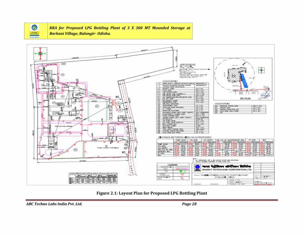
2.1 INTRO DUC TIO NBharat Petroleum Corporation Limited (BPCL) has planned to set up a new 90 TMTPALPG Bottling Plant conforming to OISD 144 with LPG Storage in the form of 3 x 300 MTMounded Storage Vessels which will be distributed through LPG Cylinders in entireOdisha Region.2.2 PROJEC T LOC ATIO NBharat Petroleum Corporation Limited has purchased the Land admeasuring approx.23.12 Acres from IDCO Growth center (Phase II) for construction of LPG bottling plant.Land is located in village Barkani, Tehsil Balangir Odisha. The layout plan for proposedLPG Bottling plant is shown in Figure 2.1.2.3 INFRA ST R UC TURE
2.3.1 COMP O UN D WALL , GA TES AN D FENC IN GA 3m high compound wall with 0.6 m high concertina wire fencing on top of the wall isproposed. One no. of 6 m wide main gate for plant with security office and emergencygate of 6 m wide has been proposed.2.3.2 KER B WALL FENC INGTo segregate the licensed area, 1.0 m height kerb wall with 1.2 meter high chain link fenceshall be provided at appropriate places.2.3.3 STO RAGE VE SSEL3 x 300 MT capacity Mounded Storage Vessels have been considered. The bullets shall beof 5.05 m diameter and 37.30 m length. However, actual dimensions shall be as perapproved design of the successful vendor. CCOE approval shall be obtained for theproposed bullets. Also calibration of bullets shall be got approved from approvedcalibration agencies by the vendor.
RRA for Proposed LPG Bottling Plant of 3 X 300 MT Mounded Storage atBarkani Village, Balangir- Odisha.
ABC Techno Labs India Pvt. Ltd. Page 15
2.3.4 FILLING CUM EMPTY CYLINDE R SHE DShed size of 65 m x 29 m shall be provided for stacking empty cylinders and fillingfacilities. Filling of LPG Cylinders will be done by 1x 24 station electronic carousel whichshall have all the required upstream and downstream facilities (like cylinderwashing/drying m/c, in-line check scales, GD/PT units, correction units, cap hammeringunit, washer replacement loop etc) complying with all guidelines and statutory norms.Additionally, adequate number of on-line valve change machines (without evacuation)shall be installed to take care of the valve leak detected cylinders.One number electronic check scale (platform type) of 50 kg capacity to be provided atunloading bay for random checking of new & pressure tested cylinders as per QAPManual.2.3.5 LPG FILLIN G FAC ILIT YOne conveyor line shall be provided for filling of 35 and 47.5 Kg cylinders with facility forOnline dosing for BMCG. In the above line a separate inline filling station shall beprovided to fill 19.35 kg cylinders, with scale accuracy of 10 gm. Special type heavy dutyreversible conveyer shall be provided for safe and easy handling of these cylinders. Onlinecylinder purging facility shall be provided with capacity 750 cylinder/hr.The list of equipments is as under.1. 1 x 24 Station Electronic Carousel with Dynamic check scale, WCU, VLD & OLD.2. Cylinder washing unit to wash empty cylinders3. Automatic valve changing machine4. Purging unit5. Chain / roller conveyor system with drive units6. One hot air sealing system7. Vapour extraction system8. CVT9. Test Bath2.3.6 FILLE D CYLIN DE R STO RAGE SHE DShed of size 65 m x 29 m with 15 m x 10 m finger loading platform (to accommodate 2lorries at a time.) will be provided. Filling shed & filled cylinder shed are interconnected
RRA for Proposed LPG Bottling Plant of 3 X 300 MT Mounded Storage atBarkani Village, Balangir- Odisha.
ABC Techno Labs India Pvt. Ltd. Page 16
by 6.0 m wide gangway for conveyors. Similarly, gangway connection of 7 m wide shall beprovided between filing shed and valve change shed. Statistical quality control loop (SQC)with roller conveyor will be provided with an inline check scale and CVT. All theloading/unloading fingers and gangway shall be provided with sprinkler coverage.2.3.7 INHO USE PRE SSURE TESTIN G FAC ILITYSeparate shed of 25 m x 10 m size shall be provided to house PT facility with LPG ventpipe from 2 x 10 head test bench extending to a point having 30 m clear distance allaround. PT shed to be located adjacent to Valve Change Shed. Adequate provision ofconveyors shall be considered for movement of cylinders.The following equipments shall be integral to the PT facilities:
Cylinder Washing tank Valve screwing & unscrewing machine Tilting type 2 x 10 head test bench with closed air and water vessels of suitablecapacity Pneumatic testing facility with air compressor capable of providing 12 kg/cm2 airpressure Painting booth with blower Flameproof/Intrinsically safe platform type electronic weighing scale of upto 50kg capacity. Ultrasonic cleaning and valve salvaging machines shall be provided.The above system will be semi automatic. In addition to the above, open hard standingwill be provided for stacking the cylinders
2.3.8 CHAIN CON VEYO R SY STEMAs per the requirement of Electronic carousel, the speed of chain conveyor system shallbe between 12 – 22 m/min. On the Introduction line and Ejection line, the speed shouldbe minimum 22 m/min and 18 m/min up to the test bath. A layout will be developedshowing the position of OLD/VLD and the location of test bath and HAS. The ratings &numbers of Drive Units will be provided commensurate with the new electronic carousel.
RRA for Proposed LPG Bottling Plant of 3 X 300 MT Mounded Storage atBarkani Village, Balangir- Odisha.
ABC Techno Labs India Pvt. Ltd. Page 17
One telescopic chain conveyors and one manual chain Conveyor each for loading andunloading Fingers shall be provided. This is adequate to cater to the requirement of 24stations.2.3.9 ELEC TR ONIC CA RO USE LCareful design shall be planned on floor keeping operational and aesthetics aspects inmind. Further, conveyors shall be designed to offer high efficiency at designed load withhelp of high efficiency motors/helical or direct mount gear boxes etc. Auto on-offoperation of loop conveyers at correction, valve & O-ring change and evacuationconveyors to be provided. Telescopic conveyors to be provided for unloading/loading ofempty/filled cylinders to and from box lorry with photoelectrical type autosensing/tripping system. All electric motors shall be of high efficiency “ Eff 1 “ grade.2.3.10 LPG PUMP / CO MPRE SSO R SHE DThe pump house will be of size 16 m x 8 m, LPG pumps (50 Cu.m / hr, 160 m Head) will beprovided for bottling. LPG compressor shed will be of size 8 m x 8 m, LPG compressor (65CFM) will be provided for unloading of bulk tank lorries. One no LPG Loading pump of 50m3/hr, 80 m Head shall be provided for loading bulk LPG. Suitable capacity cooling towerwith cooling water pumps as per requirement to be provided.2.3.11 ADMIN . / AMENITY BUIL DIN G / PLANNING ROO M480 Sq.m building will be provided to accommodate office space, conference rooms,canteen, amenities etc with internal partitions / furniture, planning room including dresschange room/toilet.2.3.12 SEC URITY CABI N3 m x 5 m security office will be provided at the main gate. The time office at second gateto license premise shall be provided.2.3.13 EN GINEE RING/CON SUMABLE S STO RE SEngineering cum consumables store of 12 m x 8 m has been proposed. This would be ashed with false ceiling for store keeper. A field toilet of 5 m x 10 m with emergency eyewash facility is also proposed adjacent to the stores.
RRA for Proposed LPG Bottling Plant of 3 X 300 MT Mounded Storage atBarkani Village, Balangir- Odisha.
ABC Techno Labs India Pvt. Ltd. Page 18
2.3.14 MCC & HT ROOM16 m x 8 m Room will be provided to house HT (Vacuum type) Breaker / LT panel etc.meeting operational and statutory requirements.Transformer shall be indoor type located behind the MCC Room in a 5 m x 5 m enclosurewith minimum safety distance as per IE Rules. Transformer shall be provided with AVRon HT side, in case necessary to eliminate unwanted power consumption due to voltagefluctuation. Suitable APFC panel to maintain plant power factor above 0.95 shall beensured. Separate arrangement bypassing main LT breaker shall be provided to maintainpower supply to critical areas (i.e. plant lighting, siren, fire control panel & road barriersetc) in case of emergency shutdown of plant.2.3.15 DG SET SHE DDG Sets having acoustic enclosures will be provided adjoining to MCC room in 10 m X 8 mshed. 250 KVA set will be used for full load plant operation while 125 KVA unit will takecare of light load and emergency power requirement. Provision of Diesel Tanks for supplyof Diesel to the DG sets will be made outside the shed.2.3.16 HT RO OMHT room of 4 m x 5 m. Location shall be frozen in consultation with state electricity board.2.3.17 CYC LE /CA R SH E DShed of size 15 m x 5.5m will be provided.2.3.18 INSPEC TIO N PLATFO R M1.5 m wide and 6m long inspection cum counting platforms will be provided in front ofsecurity gate, to check LPG packed Lorries.2.3.19 WEIGHBRI DGE50 MT capacity electronic way bridge with SAP interface shall be provided. ¼th capacitydead weights shall be provided for calibration/testing.2.3.20 TANK LO R RY GANTRYTLD gantry of size 16 m x 5.5 m for Unloading of tank lorry with MFM on common headerto facilitate automation. All unloading bays will be provided with suitable loading arms
RRA for Proposed LPG Bottling Plant of 3 X 300 MT Mounded Storage atBarkani Village, Balangir- Odisha.
ABC Techno Labs India Pvt. Ltd. Page 19
with break-away type coupling and earthing interlocks. Additionally, provision of bulkloading shall be made in two bays.2.3.21 TR UC K PARKIN G AREA/DRAINA GE SY STEMApproximately 7600 sq.m bituminized area will be developed inside the plant boundaryfor parking of 52 no’s trucks/lorries. Provision of Solar powered illumination shall beexplored to illuminate the area as part of BPCL’s RE policy. Open Drainage system will beprovided covering admin/tank lorry parking area.2.3.22 PCVO CRE W RE ST RO OM/BA RRI ER GATEA room of sizes 5 m x 10m will be provided nearer to tank lorry parking area for the useof PCVO crew. Toilet / Wash room will be provided as per requirement. Suitablebroadcast arrangement shall be made for relaying safety messages/films for enhancingPCVO crew awareness. Solar powered systems shall be explored to illuminate the area aspart of BPCL’s RE policy. Total 4 nos. of lifting barrier gate will be provided, out of which 2nos near to the time office, 1 no at emergency gate and 1 no at tank lorry parking area.2.3.23 FIRE PR OTEC TION FA C ILITIESThe following fire fighting facilities will be provided at the proposed LPG bottling plant:a) Fire water storage; 2 Nos. above ground vertical water tanks each of capacity 1850kl as per OISD requirement will be provided.b) Fire water pump house (Shed): Pump house of size 20m x 8m will be provided toaccommodate diesel driven fire water pump sets of 660 Kl/hr and two no. electricmotor driven jockey pumps of 30 kl capacity shall be provided. The room shall beprovided with OHT (Over head trolley) suitable to handle the equipments load.c) Fire hydrant system: Fire hydrant ring main covering all facilities will be providedas per the OISD requirements. Double hydrants (with hose boxes, hoses & nozzles)and fire water monitors as per the stipulations in the OISD-144 will be provided.Long range Fire Monitors shall be provided in critical areas with remote operation.d) MV Spray system: As per OISD norms for Fire Protection System.e) Fire Extinguishers: Shall be provided as per OISD norms
RRA for Proposed LPG Bottling Plant of 3 X 300 MT Mounded Storage atBarkani Village, Balangir- Odisha.
ABC Techno Labs India Pvt. Ltd. Page 20
f) Deluge Valves: Auto reset type deluge valves having manual quick bypass systemas per OISD norms shall be provided with fire protection wall. Provision foractivation of DV shall be for auto and manual modes (local & remote panel) as perOISD-144.g) All the isolation valves used in Fire fighting system should be of rising stem type.h) MCP: Manual Call Points at strategic locations as enumerated in OISD-144 shall beprovided to raise alarm (siren) and also shut down LPG operations, in case ofemergency with suitable hooter on annunciation panel at fire water pump house.2.3.24 GAS MONITO RIN G SY STEMGas monitoring system with infra red / Catalytic type sensors shall be provided as perrevised OISD standard-144. Mimic & repeater panels shall be provided at FWPH (FireWater Pump House) /Control room and security gate.2.3.25 AIR COMP RE SSO R / REC EIVER / DRYE RTwo nos. 200 CFM (to be reviewed with OEM) screw type integrated Air- compressorsalong with refrigerated Air dryers and air receivers of capacity 200 CFM shall be providedto cater to the requirement of instrument air for carousel, pneumatics, ROV etc.Shed of Size 8 m x 8 m shall be provided for housing these equipments adjacent to DGSets.2.3.26 ELEC TRIC AL SY STEMIncoming supply will be taken from State Electricity Board preferably through anindependent feeder to ensure uninterrupted power supply from grid.2.3.27 TRAN SFO RME R500 kVA transformer with provision for Automatic Voltage Regulator (AVR based onroller contact technology with permissible voltage vaiation of +/-1% and 98% plusefficiency) on HT side will be provided in the plant.2.3.28 MAXIMUM DE MAN DMaximum demand expected is 450 kVA and Connected load 500 kVA.
RRA for Proposed LPG Bottling Plant of 3 X 300 MT Mounded Storage atBarkani Village, Balangir- Odisha.
ABC Techno Labs India Pvt. Ltd. Page 21
2.3.29 ELEC TRIC AL FITTIN G SAll electrical fittings will be as per the area classification (refer OISD-113) and prevalentIE Rules. All Motors to be of Eff 1 Grade.2.3.30 MAIN IN ST R UMENT CO NTROL PANEL (MIC)Flame proof ROV control panel shall be provided at LPG Pump House with parallel displayat FWPH/Control room.2.3.31 BO RE WELLBore wells shall be dug to meet the water requirement. Suitable arrangement for storingand pumping drinking water shall be made.2.3.32 ROA DSBitumenised Roads 6.0 m wide and arterial roads connecting the main roads having widthof 3.5 m shall be provided inside the plant.2.3.33 PLANT SEC URIT Y SY ST EMThe provision of following facilities shall be ensured:
Handheld metal detector for frisking Door Frame Metal detector Mirror trolley Integrated Biometric Access Control System Digital Surveillance through CCTV cameras with memory back-up for 30 days. Allcritical areas i.e. Admin Bldg, Filling shed, LPG Pump House, Tank Farm, TLDGantry, Parking and Gate areas to be covered under constant surveillance. Perimeter surveillance Sufficient High mast illumination in parking as well as for plant.
2.3.34 VAPOUR SEALSuitable vapour seals to be provided in storm water drain at the following areas: Drains around filling & filled cylinder sheds
RRA for Proposed LPG Bottling Plant of 3 X 300 MT Mounded Storage atBarkani Village, Balangir- Odisha.
ABC Techno Labs India Pvt. Ltd. Page 22
Bulk storage Boundary
2.3.35 COM M UNIC ATION SY ST EMThe following systems to be provided: Intrinsically Safe Paging System PA System for announcement at gate Inter-com at all working stations/points as per advice Walkie-talkie for designated staff (VHF/UHF) Display of carousel performance at TC cabin & Planning
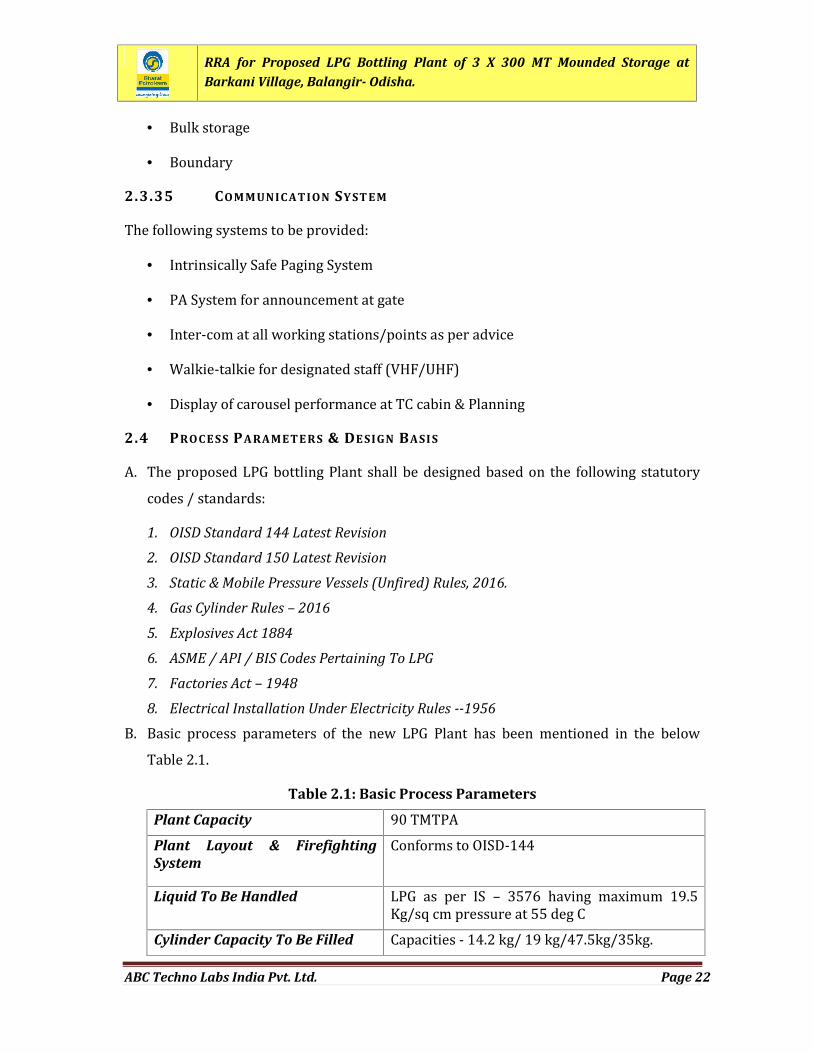
2.4 PROC E SS PA RAMETE R S & DE SIGN BASI SA. The proposed LPG bottling Plant shall be designed based on the following statutorycodes / standards:1. OISD Standard 144 Latest Revision
2. OISD Standard 150 Latest Revision
3. Static & Mobile Pressure Vessels (Unfired) Rules, 2016.
4. Gas Cylinder Rules – 2016
5. Explosives Act 1884
6. ASME / API / BIS Codes Pertaining To LPG
7. Factories Act – 1948
8. Electrical Installation Under Electricity Rules --1956B. Basic process parameters of the new LPG Plant has been mentioned in the belowTable 2.1.Table 2.1: Basic Process Parameters
Plant Capacity 90 TMTPAPlant Layout & FirefightingSystem
Conforms to OISD-144Liquid To Be Handled LPG as per IS – 3576 having maximum 19.5Kg/sq cm pressure at 55 deg CCylinder Capacity To Be Filled Capacities - 14.2 kg/ 19 kg/47.5kg/35kg.
RRA for Proposed LPG Bottling Plant of 3 X 300 MT Mounded Storage atBarkani Village, Balangir- Odisha.
ABC Techno Labs India Pvt. Ltd. Page 23
Types – Domestic/Commercial/BMCGProduct Receipt Product will be received by tank trucks.LPG Cylinder Sheds Two shed concept:1. Shed for Empty/Filling, size- 65 m x 29 m2. Filled shed – 65 m x 70 mProperty Land Demarcation Compound wall 3m height with 0.6 mconcertina coil on topLicensed Area Demarcation 1.0 m height wall with 1.2 m height chain linkfencing would be provided.No of Tank Lorry Unloading Bays Tank lorry unloading gantry with loadingfacilities in one/two baysCaptive Power Generating Sets 250 kVA DG for plant and 1 No. 125 kVA DG foryard light and jockey pump. Capacity can bereviewed with actual contract demand.
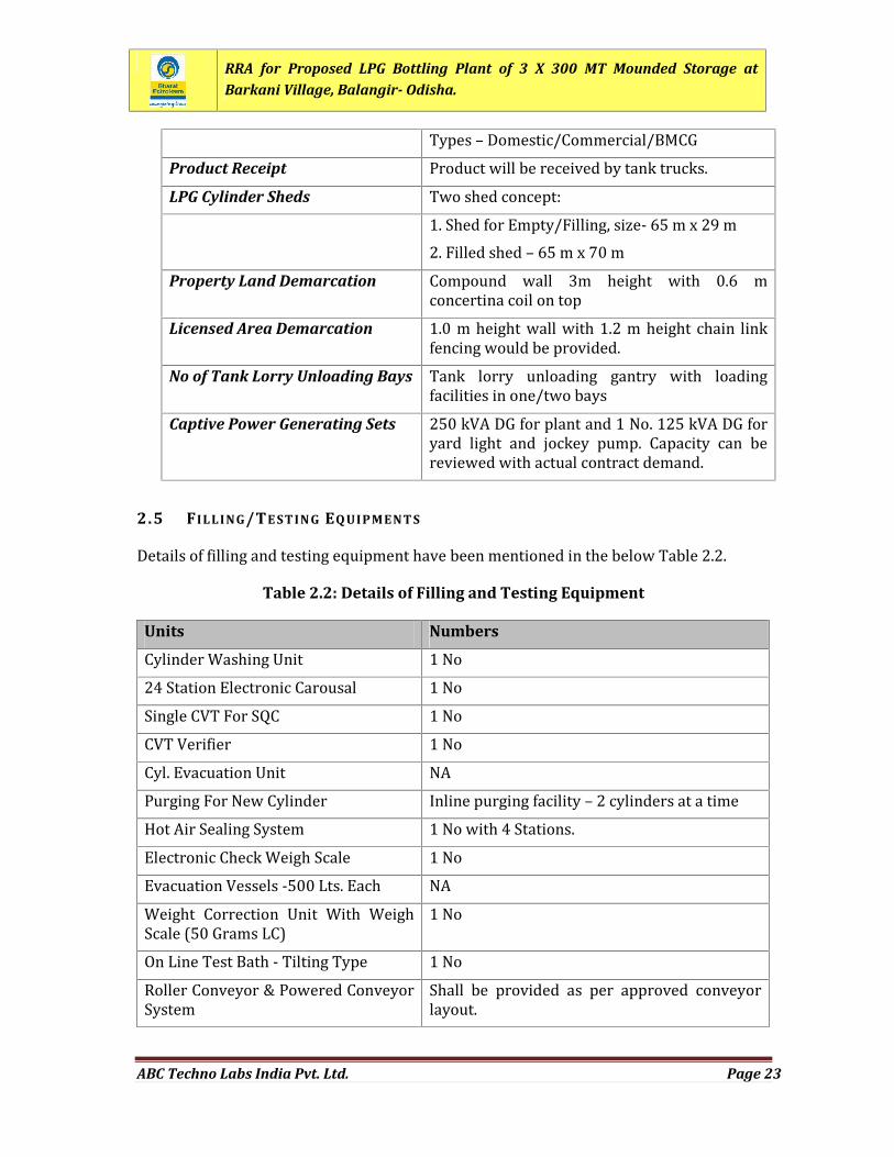
2.5 FILLING/TE STIN G EQ UIPMENT SDetails of filling and testing equipment have been mentioned in the below Table 2.2.Table 2.2: Details of Filling and Testing Equipment
Units NumbersCylinder Washing Unit 1 No24 Station Electronic Carousal 1 NoSingle CVT For SQC 1 NoCVT Verifier 1 NoCyl. Evacuation Unit NAPurging For New Cylinder Inline purging facility – 2 cylinders at a timeHot Air Sealing System 1 No with 4 Stations.Electronic Check Weigh Scale 1 NoEvacuation Vessels -500 Lts. Each NAWeight Correction Unit With WeighScale (50 Grams LC) 1 NoOn Line Test Bath - Tilting Type 1 NoRoller Conveyor & Powered ConveyorSystem Shall be provided as per approved conveyorlayout.
RRA for Proposed LPG Bottling Plant of 3 X 300 MT Mounded Storage atBarkani Village, Balangir- Odisha.
ABC Techno Labs India Pvt. Ltd. Page 24
2.6 SAFETY PHILO SOP HYLPG is a common material used extensively in households as well as industry. If itscharacteristics are understood well and proper precautions as stipulated in various codesand standards are followed, it is an easy and safe material to handle. Accordingly, in mostof the developed /developing countries, where LPG is consumed in million tons / year,specific codes and standards are available for storing and handling of LPG.2.6.1 LPG IN STALLATION S - CO DE S & STAN DAR DSCodes and standards which are generally followed for LPG installations are as follows:1. NPPA (National Fire Protection Association of USA) Standards - NFPA-58:Standard for the Storage and Handling of Liquefied Petroleum Gases - NFPA-59:LP-Gases at Utility Gas Plants2. API (American Petroleum Institute) Standards - API-2510: Design & Constructionof LPG installations3. IP (Institute of Petroleum) Standards - IP-9: Liquefied Petroleum Gas - Large BulkStorage of Pressurized and Refrigerated LPG4. The Static and Mobile Pressure Vessels (Unfired) Rules, 2016 of India (SMPVRules).5. OISD (Oil Industry Safety Directorate) Guidelines - OISD RP - 158: RecommendedPractices on Storage and Handling of Bulk Liquefied Petroleum Gas (LPG), 1997.(This is being followed by Public Sector Refineries and Oil Industry in India. It iscurrently a guide and not a mandatory code or standard). LPG storage tanks takeany other pressurized vessels may be designed as per any of the following wellknown international or local codes / standards:
ASME, Section VIII, Division I ASME, Section VIII, Division II BS 5500 IS 2825
RRA for Proposed LPG Bottling Plant of 3 X 300 MT Mounded Storage atBarkani Village, Balangir- Odisha.
ABC Techno Labs India Pvt. Ltd. Page 25
2.6.2 MOUN DE D STO RA GE F OR LPGLPG is normally stored in above ground storage mainly spheres and cylindrical tanks,namely, bullets & Horton spheres, the advantage being their accessibility for regularinspection and maintenance which is important for such storage for hazardous service.But these storages are susceptible to fire impingement and can give rise to Boiling LiquidExpanding Vapour Explosions (BLEVE).The reason for selecting mounded or buried bullets for LPG storage is to protect themfrom direct flame impingement caused by any eventual fire in the surroundings and thusprevent initiation of the sequence of events leading to an occurrence of BLEVE.The mounded storage concept basically originated from Europe and specialized codesexist in Germany such as:DIN 4681 Tl: Statutory Steel Pressure Vessels for Liquified Petroleum Gases for EarthCovered Installations, Dimensions and Equipment.During construction phase, a slight increase in the ambient noise levels is anticipated.This impact will be temporary and limited to the construction phase. Hence no permanentimpact on this account is expected.During the operational phase, no major social impact in the general area is expected.There will be no change in the occupational structure of the workforce. As there will be noemissions into air, no liquid effluents and no solid wastes no negative impact on thehealth of the inhabitants in and around the project site is expected.2.7 PHYSIC AL PR OPERTIE S OF LPGLPG is mixture of propane and butane. The physical properties of LPG are describedbelow:Product Composition : C3 & C4 mixture having nearly 50:50compositionLiquid Density : 545 kg/m3Molecular weight of Gas : 51Heat capacity ratio of the gas : 1.32 at 11.5barg and 25°CLatent heat of vaporization : 16167 KJ/Kg mole at 11.5 barg and 25°CFlash point : -104ºC - 60ºC
RRA for Proposed LPG Bottling Plant of 3 X 300 MT Mounded Storage atBarkani Village, Balangir- Odisha.
ABC Techno Labs India Pvt. Ltd. Page 26
2.8 METEOR OLOGIC AL DATAThe climate of the district is tropical with hot and dry summer and pleasant winter. Thesummer season extends from March to the middle of June followed by the rainy seasonfrom June to September.2.8.1 METEOR OLOGIC AL CO NDITI ON S I N PROJ EC T AREAThe meteorological and climatological data collected from India MeteorologicalDepartment (IMD) for Balangir IMD Station has been considered for the study. TemperatureThe mean daily maximum temperature varies from 25 oC to 40.0 oC Data collected fromBalangir IMD indicates that May is hottest month. Mean Monthly Relative HumidityRelative humidity is high during the middle of June and it’s less in the post monsoonperiod. The relative humidity in the district varies from 26% to 84% throughout the year.The mean monthly potential evapotranspiration value ranges from 45mm in December to470 mm in May. Wind VelocityThe Wind is generally light to moderate. During summer and southwest monsoonmonths, wind velocity increases. The mean annual wind speed is 3.3 Km/HR. CloudinessThe skies are generally moderately to heavily cloud during the monsoon season and inwinter season. The skies are mainly clear or lightly clouded during the December toMarch months. Winds PatternWind pattern in the area along along the project road, the prevailing winds are blownfrom NE – SW direction. Calm period is low and observed for 0.89 to 4.4% of the time.
RRA for Proposed LPG Bottling Plant of 3 X 300 MT Mounded Storage atBarkani Village, Balangir- Odisha.
ABC Techno Labs India Pvt. Ltd. Page 27
2.8.2 METEOR OLOGIC AL DATA CON SI DE RE D FO R T HE ST UDYDispersion of gases or vapours is influenced to a large extent by the atmospheric stability.The various Pasquill stability classes are:A Very UnstableB UnstableC Slightly UnstableD NeutralE StableF Very StableThe stability class at a particular location is generally dependent upon:- Time (Day or Night)- Cloud Cover- Season- Wind SpeedSix stability classes from A to F are defined while wind speed can be any numeric value.However, the number of stability class- wind speed combinations that needs to beconsidered for formulating outcome cases in any analysis is very limited. This is due tothe fact that only certain combinations of stability class and wind speed occur. Thus, forinstance many combinations e.g. A-3 m/s or B-5 m/s or F-4 m/s do not occur in nature. Asa result only one or two stability class - wind speed combinations need to be consideredto ensure reasonable completeness of a Risk Assessment. Wind speed does not influenceconsequence as much as stability class and for a given stability class, the influence of windspeed is relatively less. On the other hand consequence varies considerably with stabilityclass for the same speed.The following stability class and with wind speed combinations have been considered forthe calculation purpose:Stability Class B and Wind Speed 3 m/s during day time (B – 3 m/s),Stability Class D and Wind Speed 3 m/s during day and night time (D – 3 m/s) andStability Class E and Wind Speed 2 m/s during night time (E – 2 m/s).
RRA for Proposed LPG Bottling Plant of 3 X 300 MT Mounded Storage atBarkani Village, Balangir- Odisha.
ABC Techno Labs India Pvt. Ltd. Page 28
Figure 2.1: Layout Plan for Proposed LPG Bottling Plant
RRA for Proposed LPG Bottling Plant of 3 X 300 MT Mounded Storage atBarkani Village, Balangir- Odisha.
ABC Techno Labs India Pvt. Ltd. Page 29
CHAPTER3
HAZARD ANALYSIS
RRA for Proposed LPG Bottling Plant of 3 X 300 MT Mounded Storage atBarkani Village, Balangir- Odisha.
ABC Techno Labs India Pvt. Ltd. Page 30
CHAPTER 3: HAZARD ANALYSIS
3.1 INTRO DUC TIO NLiquefied Petroleum Gas (LPG) plant deals with handling and storage of LPG, which isgenerally hazardous in nature by virtue of their intrinsic chemical properties or theirtemperature or pressure of operation or a combination of these. Fire, explosion,hazardous release or a combination of these are the hazards associated with proposedLPG plant. These have resulted in the development of more comprehensive, systematicand sophisticated methods of Safety Engineering such as Hazard Analysis and RiskAssessment to improve upon the integrity, reliability and safety of industrial plants.The primary emphasis in safety engineering is to reduce risk to human life andenvironment. The broad tools attempt to minimize the chances of accidents occurring.Yet, there always exists, no matter how remote, that small probability of a major accidentoccurring. If the accident involves highly hazardous materials in sufficient largequantities, the consequences may be serious to the plant, to surrounding areas and thepopulations therein.3.2 RISK ASSE SSME NT AN D HA ZAR D IDENTIFIC ATIONRisk is defined as the unwanted consequences of a particular activity in relation to thelikelihood that this may occur. Risk Assessment thus comprises of two variables,magnitude of consequences and the probability of occurrence of accident.The first step in risk assessment is identification of hazards. Hazard is defined as aphysical or chemical condition with the potential of accident which can cause damage topeople, property or the environment. Hazards are identified by careful review of plantoperation and nature of materials used. The various scenarios by which an accident canoccur are then determined, concurrently study of both probability and the consequencesof an accident is carried out and finally risk assessment is made. If this risk is acceptablethen the study is complete. If the risk is unacceptable then the system must be modifiedand the procedure is restarted.
RRA for Proposed LPG Bottling Plant of 3 X 300 MT Mounded Storage atBarkani Village, Balangir- Odisha.
ABC Techno Labs India Pvt. Ltd. Page 31
3.3 LIQ UEFIE D PETR OLEUM GA S (LPG)Liquefied Petroleum Gas (LPG) is a colourless and odourless gas. It is highly flammable atnormal temperature and pressure (flammability limits 2.2% to 9.6 % in air), thereforethere should be no ignition sources in close proximity to areas where LPG is stored andhandled. On release it may give rise to both fire and explosion hazards. LPG is a blend ofPropane and Butane, readily liquefied under moderate pressure. LPG is 1.5 to 2.0 timesheavier than air, therefore, difficult to disperse. It should never be used or stored belowground, as this could result in asphyxiation when released in a confined space. Since LPGhas only a faint scent, a mercaptan odorant is added to help in detection of its leakageespecially when used as a domestic fuel. In the event of a LPG leak, the vapourisation ofliquid cools the surrounding atmospheric air and condenses the water vapour containedin it to form a whitish fog, which is easy to observe. LPG in fairly large concentrationsdisplaces oxygen leading to a nauseous or suffocating feeling.Physical and chemical properties of LPG are as given below:Boiling Point : -42 ºC - 0ºCVapour Pressure : 300 – 1400 kPa @ 40ºCSolubility in Water @ 20ºC : <200ppmPhysical State : Liquid (gas at ambient pressure)Colour : ColourlessSpecific Gravity : Liquid 0.51 – 0.58 (water = 1)Vapour 1.52 – 2.01 (air = 1)Autoignition Temperature : 466.1 ºCFlammable Limits LELLower Flammability Limit (LFL) : 2.2% (in air v/v)Flammable Limits UELUpper Flammability Limit (UFL) : 9.6% (in air v/v)As part of LPG transportation, storage and bottling for local distribution, BPCL has optedfor mounded bullets for storage of LPG. Hence in this case, there is no possibility ofBoiling Liquid Expanding Vapour Explosion (BLEVE) as in the event of early fire, flame
RRA for Proposed LPG Bottling Plant of 3 X 300 MT Mounded Storage atBarkani Village, Balangir- Odisha.
ABC Techno Labs India Pvt. Ltd. Page 32
impingement or heating of bullet will not be possible on mounded bullet. Therefore, frommounded bullets, release of LPG is possible only from leakage in piping, valves or flanges,etc.3.4 HAZAR DS F RO M LPG STORAG E AN D HAN DLIN G
3.4.1 JET FIREIf released LPG from hole/opening is ignited immediately, jet fire may take place. Theextent of injury to people depends on the heat flux and duration of exposure to heat.3.4.2 VAPOUR CLO UD EXPLOSI ONIf released LPG is not ignited immediately, the cloud of vapour LPG will spread in thesurrounding area. LPG vapours are heavier than air and tend to settle down at lower level.As long as the LPG concentration is between the lower and higher flammability limits, theLPG vapour cloud may be set on fire by an ignition source. For generation of overpressure effect, some degree of confinement of the flammable cloud is required.3.4.3 FLASH FI REWhen released quantities of LPG are not ignited immediately, vapour cloud of LPGspreads in the surrounding area, some portion of LPG vapour cloud will have LPGconcentration between the lower and upper flammable limits, the LPG vapour cloud maybe set on fire by an ignition source in entire length of flammable LPG vapour cloudresulting flash fire. In the event of flash fire, essentially, no over pressure effect ispossible.3.5 HAZAR DO US CO N DITI ONS DUE TO RELEA SE OF LPGAs a result of release of LPG followed by immediate or delayed ignition, followinghazardous conditions may be encountered:3.5.1 THE RMAL EFFEC TSIn case of jet fire, thermal effect is likely to cause injury or damage to people and damageto objects. A substantial body of experimental data exists and forms the basis for thermaleffect estimation. The consequence caused by exposure to heat radiation is a function of: Radiation energy onto the human body [kW/m2];
RRA for Proposed LPG Bottling Plant of 3 X 300 MT Mounded Storage atBarkani Village, Balangir- Odisha.
ABC Techno Labs India Pvt. Ltd. Page 33
Exposure duration [sec]; Protection of the skin tissue (clothed or naked body).The following damage distances for thermal radiation are used in the risk analysis:37.5 kW/m2 : Damage to process equipment. 100% fatality in 60 s exposure. 1%fatality in 10 s exposure.12.5 kW/m2 : First degree burn in 10 s exposure4.0 kW/m2 : First degree burn in 30 s exposure
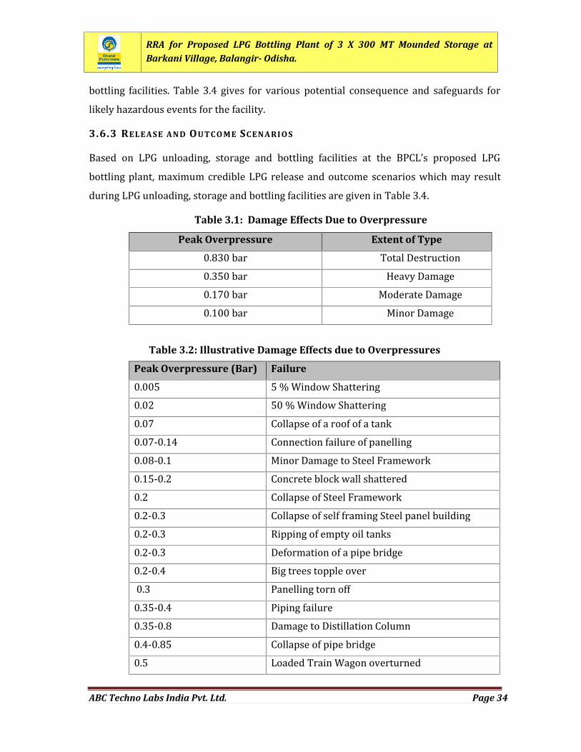
3.5.2 DELAYE D IGNITION AN D EXPL O SIONIn case of delayed ignition of LPG cloud, two physical effects may occur in following ways: Flash fire over the whole or part of the LPG vapour cloud; Vapour cloud explosion that results in blast wave with typical peak overpressuresin circle around the ignition source. Vapour cloud explosion to occur some degreeof confinement is essential.TNO Multi-energy method is used to calculate the blast overpressure. Table 3.1 givesextent of damage with respect to the peak overpressure resulting from a blast wave:Table 3.2 given provides an illustrative listing of damage effects caused by peakoverpressure.
3.6 IDE NTIFIC ATION OF HAZAR D FO R LPG UNLOADI NG , STO RAGE AN D BOTTLING
FAC ILITIES
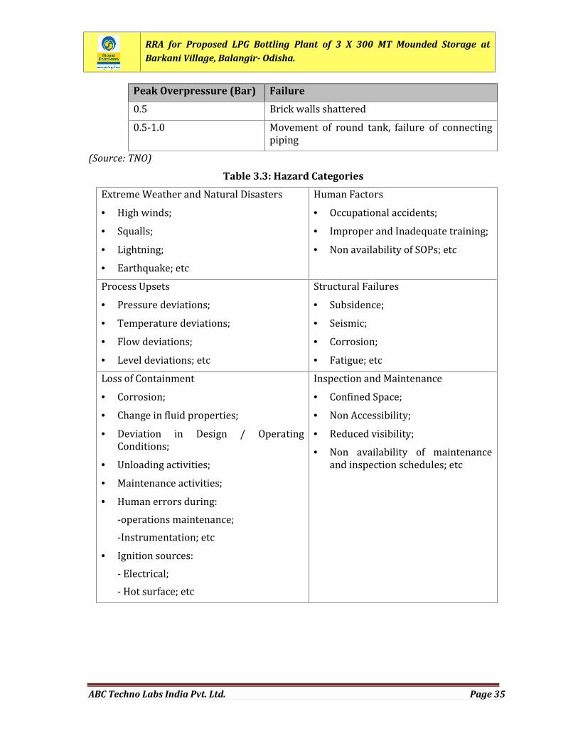
3.6.1 CATEG ORIE S OF HAZA R DSFor identification of hazards during unloading, storage and bottling of LPG, it is essentialto identify categories of hazard. Hazard categories, which may be responsible foraccidental release of LPG from proposed LPG bottling plant are listed in Table 3.3.3.6.2 HAZAR D IDENTIFIC ATION (HAZID)Hazard identification (HAZID) for the proposed LPG unloading, storage and bottlingfacilities has been carried out for likely hazardous events which may cause major accidenthazards. A systematic investigation has been carried with special focus on external eventsthat could potentially impact the operation and safety of LPG unloading, storage and
RRA for Proposed LPG Bottling Plant of 3 X 300 MT Mounded Storage atBarkani Village, Balangir- Odisha.
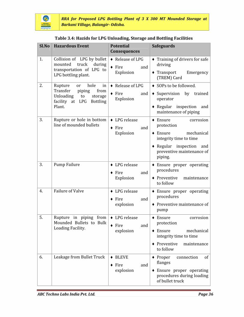
ABC Techno Labs India Pvt. Ltd. Page 34
bottling facilities. Table 3.4 gives for various potential consequence and safeguards forlikely hazardous events for the facility.3.6.3 RELEASE AN D OUTC O ME SC ENARI O SBased on LPG unloading, storage and bottling facilities at the BPCL’s proposed LPGbottling plant, maximum credible LPG release and outcome scenarios which may resultduring LPG unloading, storage and bottling facilities are given in Table 3.4.
Table 3.1: Damage Effects Due to Overpressure
Peak Overpressure Extent of Type0.830 bar Total Destruction0.350 bar Heavy Damage0.170 bar Moderate Damage0.100 bar Minor DamageTable 3.2: Illustrative Damage Effects due to Overpressures
Peak Overpressure (Bar) Failure0.005 5 % Window Shattering0.02 50 % Window Shattering0.07 Collapse of a roof of a tank0.07-0.14 Connection failure of panelling0.08-0.1 Minor Damage to Steel Framework0.15-0.2 Concrete block wall shattered0.2 Collapse of Steel Framework0.2-0.3 Collapse of self framing Steel panel building0.2-0.3 Ripping of empty oil tanks0.2-0.3 Deformation of a pipe bridge0.2-0.4 Big trees topple over0.3 Panelling torn off0.35-0.4 Piping failure0.35-0.8 Damage to Distillation Column0.4-0.85 Collapse of pipe bridge0.5 Loaded Train Wagon overturned
RRA for Proposed LPG Bottling Plant of 3 X 300 MT Mounded Storage atBarkani Village, Balangir- Odisha.
ABC Techno Labs India Pvt. Ltd. Page 35
Peak Overpressure (Bar) Failure0.5 Brick walls shattered0.5-1.0 Movement of round tank, failure of connectingpiping(Source: TNO)
Table 3.3: Hazard CategoriesExtreme Weather and Natural Disasters High winds; Squalls; Lightning; Earthquake; etc
Human Factors Occupational accidents; Improper and Inadequate training; Non availability of SOPs; etc
Process Upsets Pressure deviations; Temperature deviations; Flow deviations; Level deviations; etc
Structural Failures Subsidence; Seismic; Corrosion; Fatigue; etcLoss of Containment
Corrosion; Change in fluid properties; Deviation in Design / OperatingConditions; Unloading activities; Maintenance activities; Human errors during:-operations maintenance;-Instrumentation; etc Ignition sources:- Electrical;- Hot surface; etc
Inspection and Maintenance Confined Space; Non Accessibility; Reduced visibility; Non availability of maintenanceand inspection schedules; etc
RRA for Proposed LPG Bottling Plant of 3 X 300 MT Mounded Storage atBarkani Village, Balangir- Odisha.
ABC Techno Labs India Pvt. Ltd. Page 36
Table 3.4: Hazids for LPG Unloading, Storage and Bottling Facilities
Sl.No Hazardous Event PotentialConsequences
Safeguards
1. Collision of LPG by bulletmounted truck duringtransportation of LPG toLPG bottling plant. Release of LPG Fire andExplosion
Training of drivers for safedriving Transport Emergency(TREM) Card2. Rupture or hole inTransfer piping fromUnloading to storagefacility at LPG BottlingPlant.
Release of LPG Fire andExplosion
SOPs to be followed. Supervision by trainedoperator Regular inspection andmaintenance of piping3. Rupture or hole in bottomline of mounded bullets LPG release
Fire andExplosion Ensure corrosionprotection Ensure mechanicalintegrity time to time Regular inspection andpreventive maintenance ofpiping.3. Pump Failure LPG release
Fire andExplosion Ensure proper operatingprocedures Preventive maintenanceto follow4. Failure of Valve LPG release
Fire andexplosion Ensure proper operatingprocedures Preventive maintenance ofpump5. Rupture in piping fromMounded Bullets to BulkLoading Facility. LPG release
Fire andexplosion Ensure corrosionprotection Ensure mechanicalintegrity time to time Preventive maintenanceto follow6. Leakage from Bullet Truck BLEVE
Fire andexplosion Proper connection offlanges Ensure proper operatingprocedures during loadingof bullet truck
RRA for Proposed LPG Bottling Plant of 3 X 300 MT Mounded Storage atBarkani Village, Balangir- Odisha.
ABC Techno Labs India Pvt. Ltd. Page 37
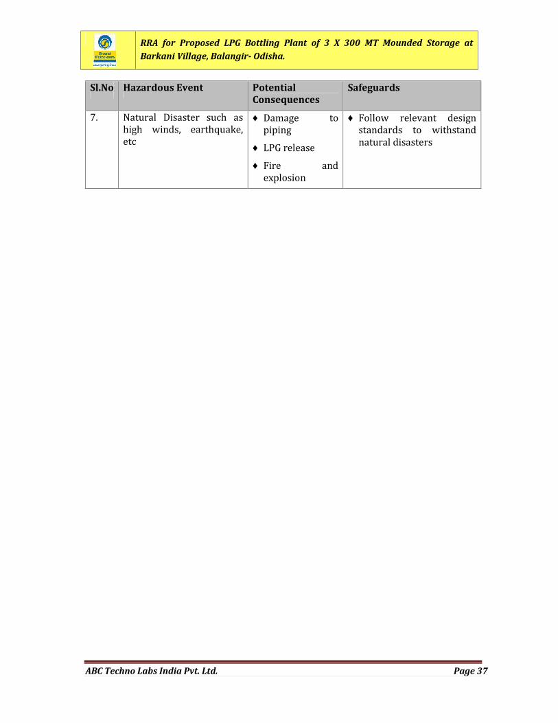
Sl.No Hazardous Event PotentialConsequences
Safeguards
7. Natural Disaster such ashigh winds, earthquake,etc Damage topiping LPG release Fire andexplosion
Follow relevant designstandards to withstandnatural disasters
RRA for Proposed LPG Bottling Plant of 3 X 300 MT Mounded Storage atBarkani Village, Balangir- Odisha.
ABC Techno Labs India Pvt. Ltd. Page 38
CHAPTER 4
HAZARD & OPERABILITY (HAZOP)STUDY
RRA for Proposed LPG Bottling Plant of 3 X 300 MT Mounded Storage atBarkani Village, Balangir- Odisha.
ABC Techno Labs India Pvt. Ltd. Page 39
CHAPTER 4: HAZARD & OPERABILITY (HAZOP) STUDY
4.1 HAZOP ST UDY FO R MOUN DE D STO RA GE OF LPGThe proposed plant will unload and store LPG in mounded bullets and bottling will takeplace in cylinders. At the proposed plant, LPG will be handled with the desired designedoperating parameters like temperature, pressure, flow, level etc. In an unlikely event ofany deviation in operating parameters, hazardous conditions may be arisen. Therefore,systematic hazard and operability (HAZOP) study has been carried for storage andhandling of hazardous chemicals. The main purpose of the HAZOP study is to identifyspecific hazard and operability issues, which could lead to risks to personnel, propertyand environment or operational problems during storage and handling of LPG.4.2 METHO DOL OGY FO R HAZOP STUDYThe methodology for the HAZOP was as adopted internationally as per guidelines of ICI,UK and CCPS, AICHE. Hazard and operability (HAZOP) study was undertaken by theapplication of a formal, systematic, and critical examination of the process andengineering intentions of process design. The potential for hazard was thus assessed andmalfunctions of the individual items of equipment and the consequences for a wholesystem were identified. The examination of the design was structured around a specificset of guidewords, which ensure complete coverage of all possible problems whileallowing sufficient flexibility for an imaginative approach.The overall aims that a HAZOP study addresses are:i. To identify all deviations from the way the design is expected to work, their causesand all the hazards and operability problems associated with these deviations.ii. To decide whether action is required to control the hazard or the operabilityproblem and if so to identify the ways in which the problems can be solved.iii. To identify cases where a decision cannot be made immediately and to decide onwhat information or action is required.
RRA for Proposed LPG Bottling Plant of 3 X 300 MT Mounded Storage atBarkani Village, Balangir- Odisha.
ABC Techno Labs India Pvt. Ltd. Page 40
Various terms with special meaning are used in conducting a HAZOP study. Theseinclude:Node DeviationParameter CauseIntention ConsequenceGuideword Recommendation4.3 UNDE RTAKIN G THE ST UDYThe HAZOP study team considered each part of process design in turn by applying theHAZOP guidewords and analysing the causes and consequences of possible deviations.Thus, the study sessions followed through a series of steps repeatedly. The followingseven steps were repeated many times during the HAZOP.a. Apply the guidewordb. Develop a deviationc. Examine possible causesd. Examine consequencese. Consider hazards or operability problemsf. Decide upon actiong. Make a record of the discussions and decisions4.4 FAC ILITIES CON SI DE R ED FO R HAZOP ST UDYLPG handling and storage system having P&I diagram No. BOLA-LPG/P&ID/16-17/01was considered for HAZOP study. P&I Diagram No. BOLA-LPG/P&ID/16-17/01 has beenshown in Figure 4.1.4.5 HAZOP WO RK SHEET SBy following the above-mentioned methodology, HAZOP worksheets have beendeveloped for important nodes during HAZOP sessions. The HAZOP worksheets are givenin Table 4.1 to Table 4.9.
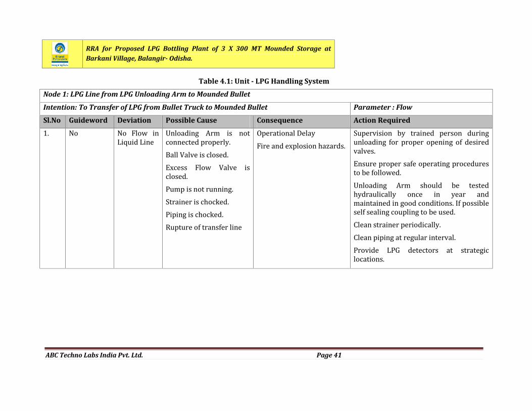
RRA for Proposed LPG Bottling Plant of 3 X 300 MT Mounded Storage atBarkani Village, Balangir- Odisha.
ABC Techno Labs India Pvt. Ltd. Page 41
Table 4.1: Unit - LPG Handling System
Node 1: LPG Line from LPG Unloading Arm to Mounded Bullet
Intention: To Transfer of LPG from Bullet Truck to Mounded Bullet Parameter : Flow
Sl.No Guideword Deviation Possible Cause Consequence Action Required1. No No Flow inLiquid Line Unloading Arm is notconnected properly.Ball Valve is closed.Excess Flow Valve isclosed.Pump is not running.Strainer is chocked.Piping is chocked.Rupture of transfer line
Operational DelayFire and explosion hazards. Supervision by trained person duringunloading for proper opening of desiredvalves.Ensure proper safe operating proceduresto be followed.Unloading Arm should be testedhydraulically once in year andmaintained in good conditions. If possibleself sealing coupling to be used.Clean strainer periodically.Clean piping at regular interval.Provide LPG detectors at strategiclocations.
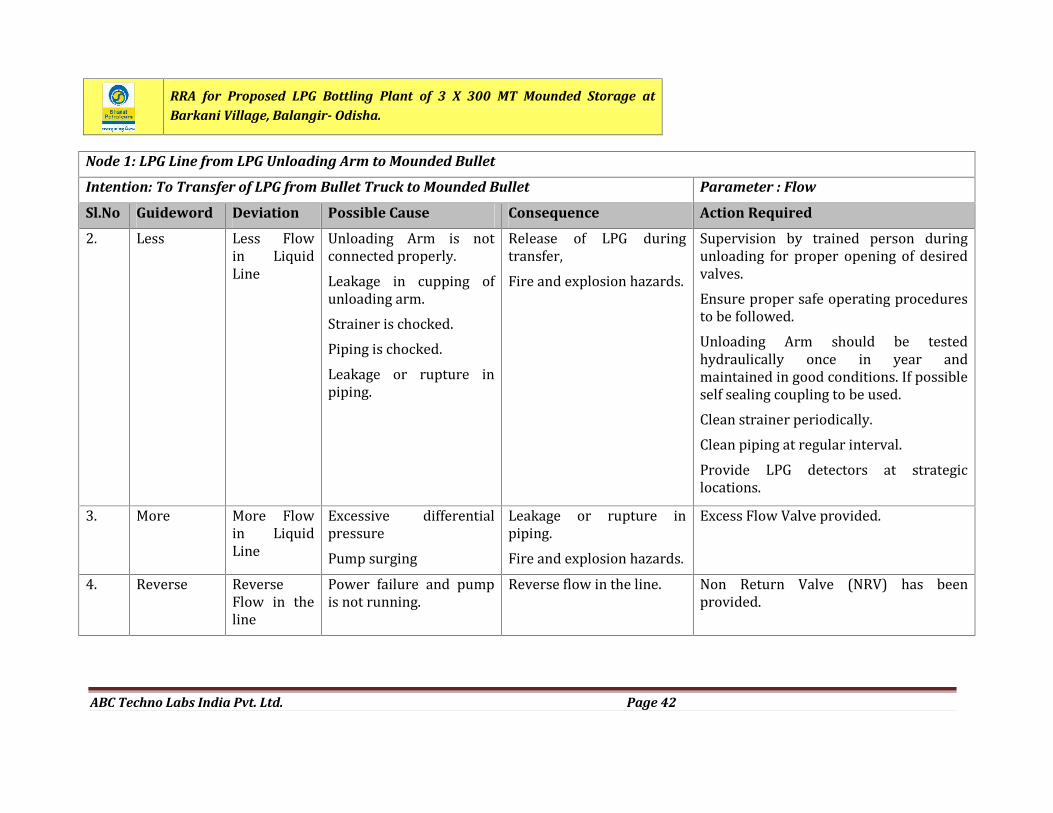
RRA for Proposed LPG Bottling Plant of 3 X 300 MT Mounded Storage atBarkani Village, Balangir- Odisha.
ABC Techno Labs India Pvt. Ltd. Page 42
Node 1: LPG Line from LPG Unloading Arm to Mounded Bullet
Intention: To Transfer of LPG from Bullet Truck to Mounded Bullet Parameter : Flow
Sl.No Guideword Deviation Possible Cause Consequence Action Required2. Less Less Flowin LiquidLine Unloading Arm is notconnected properly.Leakage in cupping ofunloading arm.Strainer is chocked.Piping is chocked.Leakage or rupture inpiping.
Release of LPG duringtransfer,Fire and explosion hazards.Supervision by trained person duringunloading for proper opening of desiredvalves.Ensure proper safe operating proceduresto be followed.Unloading Arm should be testedhydraulically once in year andmaintained in good conditions. If possibleself sealing coupling to be used.Clean strainer periodically.Clean piping at regular interval.Provide LPG detectors at strategiclocations.3. More More Flowin LiquidLine Excessive differentialpressurePump surging
Leakage or rupture inpiping.Fire and explosion hazards.Excess Flow Valve provided.
4. Reverse ReverseFlow in theline Power failure and pumpis not running. Reverse flow in the line. Non Return Valve (NRV) has beenprovided.
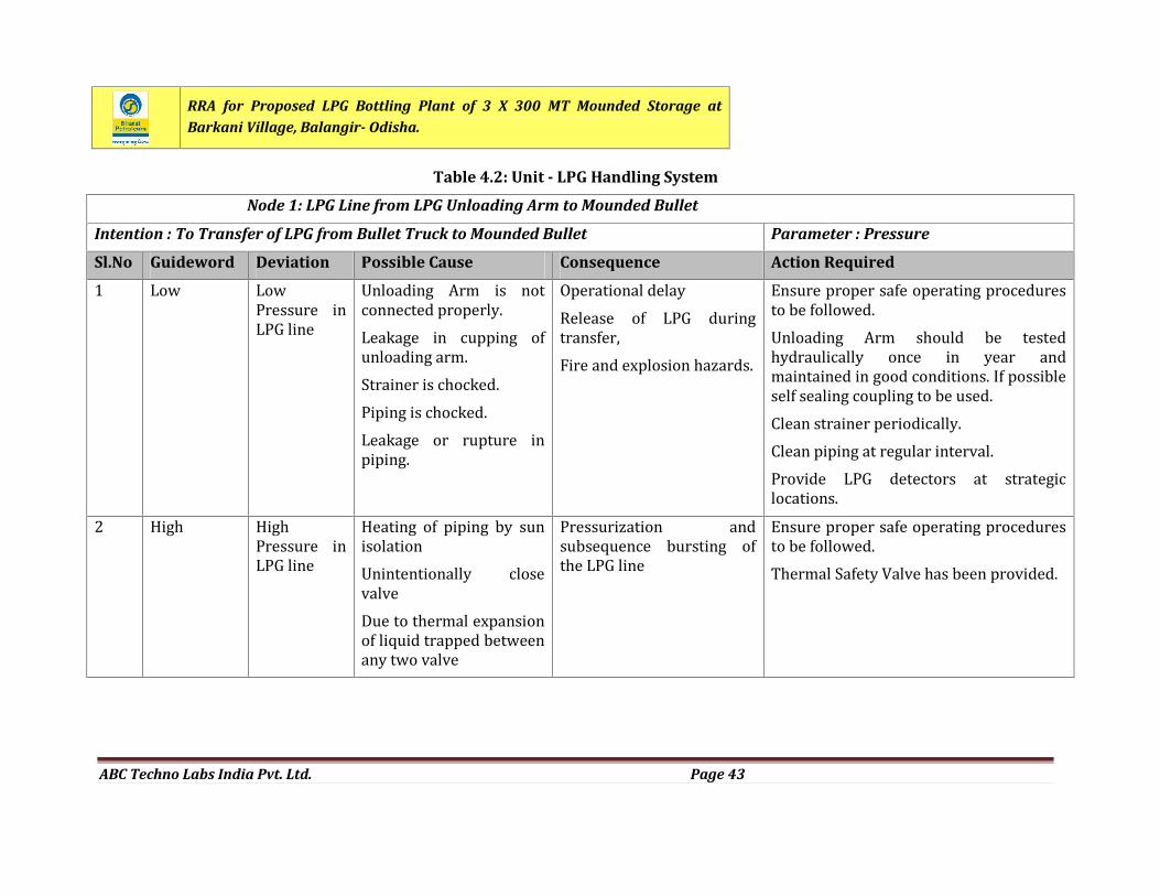
RRA for Proposed LPG Bottling Plant of 3 X 300 MT Mounded Storage atBarkani Village, Balangir- Odisha.
ABC Techno Labs India Pvt. Ltd. Page 43
Table 4.2: Unit - LPG Handling System
Node 1: LPG Line from LPG Unloading Arm to Mounded Bullet
Intention : To Transfer of LPG from Bullet Truck to Mounded Bullet Parameter : Pressure
Sl.No Guideword Deviation Possible Cause Consequence Action Required1 Low LowPressure inLPG line Unloading Arm is notconnected properly.Leakage in cupping ofunloading arm.Strainer is chocked.Piping is chocked.Leakage or rupture inpiping.
Operational delayRelease of LPG duringtransfer,Fire and explosion hazards.Ensure proper safe operating proceduresto be followed.Unloading Arm should be testedhydraulically once in year andmaintained in good conditions. If possibleself sealing coupling to be used.Clean strainer periodically.Clean piping at regular interval.Provide LPG detectors at strategiclocations.2 High HighPressure inLPG line Heating of piping by sunisolationUnintentionally closevalveDue to thermal expansionof liquid trapped betweenany two valve
Pressurization andsubsequence bursting ofthe LPG line Ensure proper safe operating proceduresto be followed.Thermal Safety Valve has been provided.
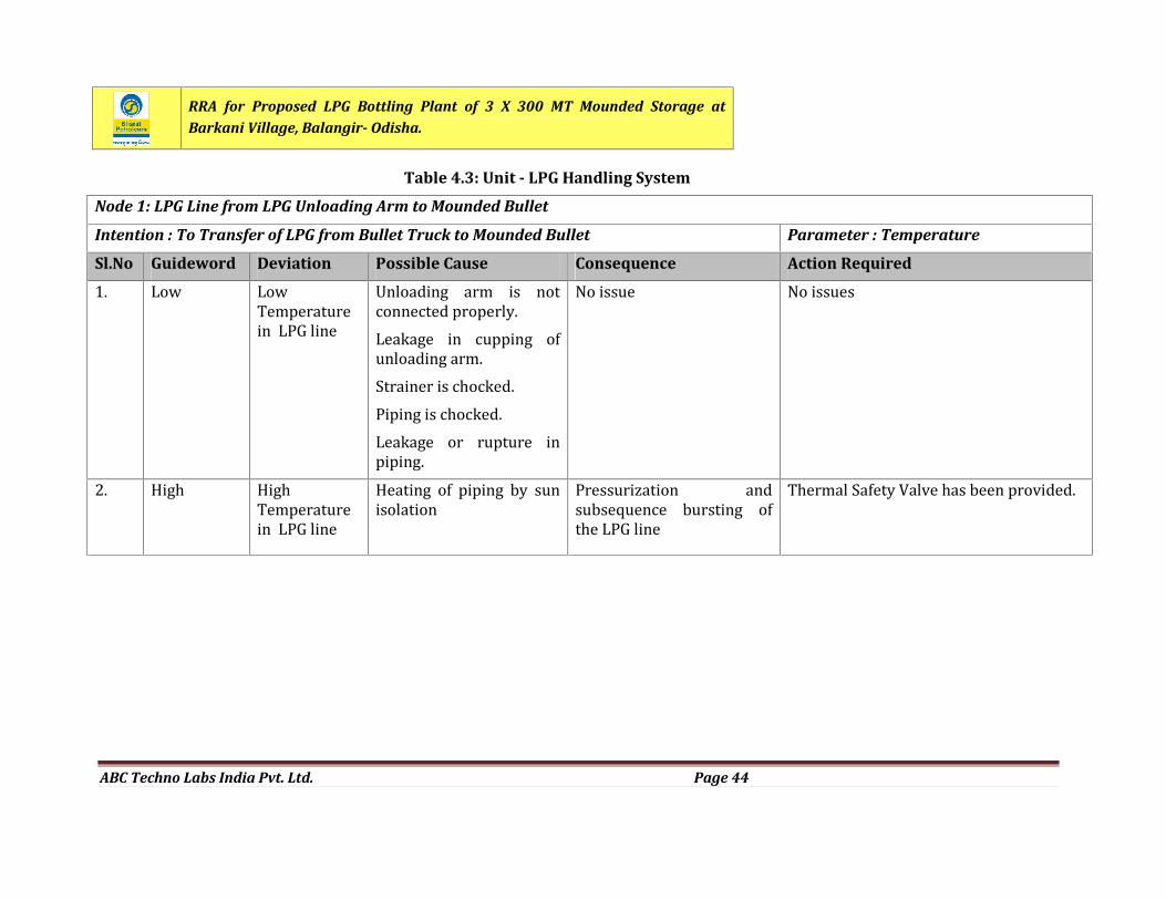
RRA for Proposed LPG Bottling Plant of 3 X 300 MT Mounded Storage atBarkani Village, Balangir- Odisha.
ABC Techno Labs India Pvt. Ltd. Page 44
Table 4.3: Unit - LPG Handling System
Node 1: LPG Line from LPG Unloading Arm to Mounded Bullet
Intention : To Transfer of LPG from Bullet Truck to Mounded Bullet Parameter : Temperature
Sl.No Guideword Deviation Possible Cause Consequence Action Required1. Low LowTemperaturein LPG line Unloading arm is notconnected properly.Leakage in cupping ofunloading arm.Strainer is chocked.Piping is chocked.Leakage or rupture inpiping.
No issue No issues
2. High HighTemperaturein LPG line Heating of piping by sunisolation Pressurization andsubsequence bursting ofthe LPG line Thermal Safety Valve has been provided.
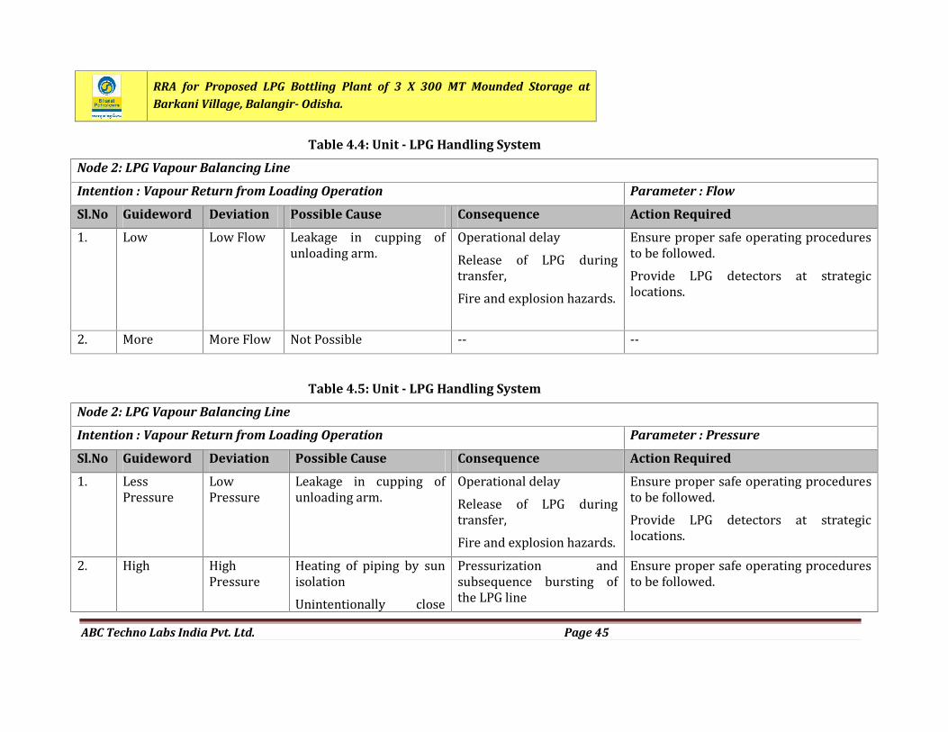
RRA for Proposed LPG Bottling Plant of 3 X 300 MT Mounded Storage atBarkani Village, Balangir- Odisha.
ABC Techno Labs India Pvt. Ltd. Page 45
Table 4.4: Unit - LPG Handling System
Node 2: LPG Vapour Balancing Line
Intention : Vapour Return from Loading Operation Parameter : Flow
Sl.No Guideword Deviation Possible Cause Consequence Action Required1. Low Low Flow Leakage in cupping ofunloading arm. Operational delayRelease of LPG duringtransfer,Fire and explosion hazards.Ensure proper safe operating proceduresto be followed.Provide LPG detectors at strategiclocations.
2. More More Flow Not Possible -- --Table 4.5: Unit - LPG Handling System
Node 2: LPG Vapour Balancing Line
Intention : Vapour Return from Loading Operation Parameter : Pressure
Sl.No Guideword Deviation Possible Cause Consequence Action Required1. LessPressure LowPressure Leakage in cupping ofunloading arm. Operational delayRelease of LPG duringtransfer,Fire and explosion hazards.Ensure proper safe operating proceduresto be followed.Provide LPG detectors at strategiclocations.2. High HighPressure Heating of piping by sunisolationUnintentionally close
Pressurization andsubsequence bursting ofthe LPG line Ensure proper safe operating proceduresto be followed.
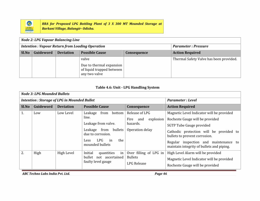
RRA for Proposed LPG Bottling Plant of 3 X 300 MT Mounded Storage atBarkani Village, Balangir- Odisha.
ABC Techno Labs India Pvt. Ltd. Page 46
Node 2: LPG Vapour Balancing Line
Intention : Vapour Return from Loading Operation Parameter : Pressure
Sl.No Guideword Deviation Possible Cause Consequence Action RequiredvalveDue to thermal expansionof liquid trapped betweenany two valveThermal Safety Valve has been provided.
Table 4.6: Unit - LPG Handling System
Node 3: LPG Mounded Bullets
Intention : Storage of LPG in Mounded Bullet Parameter : Level
Sl.No Guideword Deviation Possible Cause Consequence Action Required1. Low Low Level Leakage from bottomline.Leakage from valve.Leakage from bulletsdue to corrosion.Less LPG in themounded bullets
Release of LPGFire and explosionhazards.Operation delayMagnetic Level Indicator will be providedRocheste Gauge will be providedSGTP Tube Gauge providedCathodic protection will be provided tobullets to prevent corrosion.Regular inspection and maintenance tomaintain integrity of bullets and piping.2. High High Level Initial quantities inbullet not ascertainedfaulty level gauge Over filling of LPG inBulletsLPG ReleaseHigh Level Alarm will be providedMagnetic Level Indicator will be providedRocheste Gauge will be provided
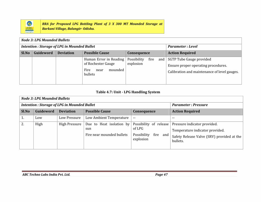
RRA for Proposed LPG Bottling Plant of 3 X 300 MT Mounded Storage atBarkani Village, Balangir- Odisha.
ABC Techno Labs India Pvt. Ltd. Page 47
Node 3: LPG Mounded Bullets
Intention : Storage of LPG in Mounded Bullet Parameter : Level
Sl.No Guideword Deviation Possible Cause Consequence Action RequiredHuman Error in Readingof Rochester GaugeFire near moundedbulletsPossibility fire andexplosion SGTP Tube Gauge providedEnsure proper operating procedures.Calibration and maintenance of level gauges.
Table 4.7: Unit - LPG Handling System
Node 3: LPG Mounded Bullets
Intention : Storage of LPG in Mounded Bullet Parameter : Pressure
Sl.No Guideword Deviation Possible Cause Consequence Action Required1. Low Low Pressure Low Ambient Temperature -- --2. High High Pressure Due to Heat isolation bysunFire near mounded bulletsPossibility of releaseof LPGPossibility fire andexplosion
Pressure indicator provided.Temperature indicator provided.Safety Release Valve (SRV) provided at thebullets.
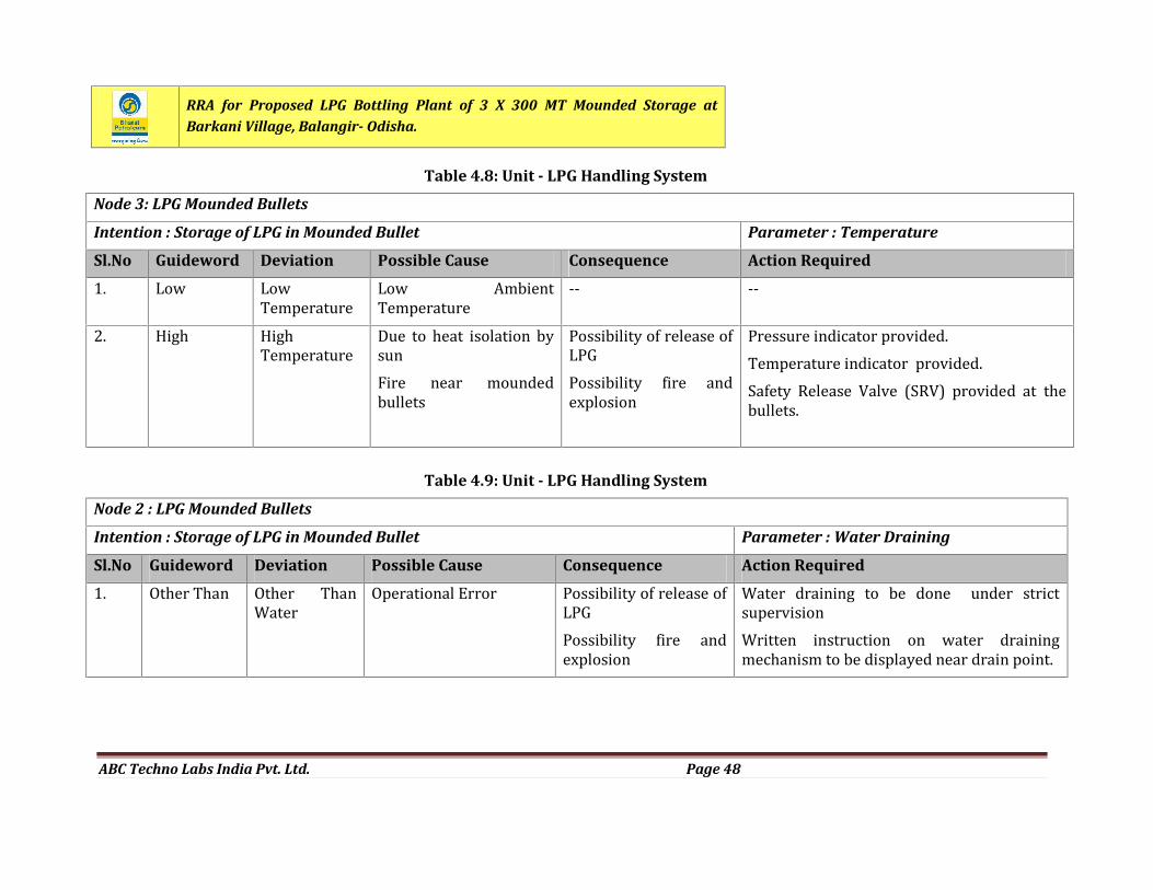
RRA for Proposed LPG Bottling Plant of 3 X 300 MT Mounded Storage atBarkani Village, Balangir- Odisha.
ABC Techno Labs India Pvt. Ltd. Page 48
Table 4.8: Unit - LPG Handling System
Node 3: LPG Mounded Bullets
Intention : Storage of LPG in Mounded Bullet Parameter : Temperature
Sl.No Guideword Deviation Possible Cause Consequence Action Required1. Low LowTemperature Low AmbientTemperature -- --2. High HighTemperature Due to heat isolation bysunFire near moundedbullets
Possibility of release ofLPGPossibility fire andexplosionPressure indicator provided.Temperature indicator provided.Safety Release Valve (SRV) provided at thebullets.
Table 4.9: Unit - LPG Handling System
Node 2 : LPG Mounded Bullets
Intention : Storage of LPG in Mounded Bullet Parameter : Water Draining
Sl.No Guideword Deviation Possible Cause Consequence Action Required1. Other Than Other ThanWater Operational Error Possibility of release ofLPGPossibility fire andexplosionWater draining to be done under strictsupervisionWritten instruction on water drainingmechanism to be displayed near drain point.
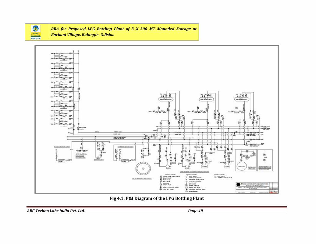
RRA for Proposed LPG Bottling Plant of 3 X 300 MT Mounded Storage atBarkani Village, Balangir- Odisha.
ABC Techno Labs India Pvt. Ltd. Page 49
Fig 4.1: P&I Diagram of the LPG Bottling Plant
RRA for Proposed LPG Bottling Plant of 3 X 300 MT Mounded Storage atBarkani Village, Balangir- Odisha.
ABC Techno Labs India Pvt. Ltd. Page 50
CHAPTER 5
CONSEQUENCE ANALYSIS
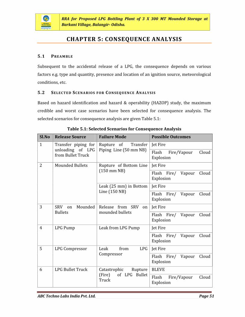
RRA for Proposed LPG Bottling Plant of 3 X 300 MT Mounded Storage atBarkani Village, Balangir- Odisha.
ABC Techno Labs India Pvt. Ltd. Page 51
CHAPTER 5: CONSEQUENCE ANALYSIS
5.1 PREAM BLESubsequent to the accidental release of a LPG, the consequence depends on variousfactors e.g. type and quantity, presence and location of an ignition source, meteorologicalconditions, etc.5.2 SELEC TE D SC ENA RIO S FOR CON SEQ UENC E AN ALYSI SBased on hazard identification and hazard & operability (HAZOP) study, the maximumcredible and worst case scenarios have been selected for consequence analysis. Theselected scenarios for consequence analysis are given Table 5.1:
Table 5.1: Selected Scenarios for Consequence Analysis
Sl.No Release Source Failure Mode Possible Outcomes1 Transfer piping forunloading of LPGfrom Bullet Truck Rupture of TransferPiping Line (50 mm NB) Jet FireFlash Fire/Vapour CloudExplosion2 Mounded Bullets Rupture of Bottom Line(150 mm NB) Jet FireFlash Fire/ Vapour CloudExplosionLeak (25 mm) in BottomLine (150 NB) Jet FireFlash Fire/ Vapour CloudExplosion3 SRV on MoundedBullets Release from SRV onmounded bullets Jet FireFlash Fire/ Vapour CloudExplosion4 LPG Pump Leak from LPG Pump Jet FireFlash Fire/ Vapour CloudExplosion5 LPG Compressor Leak from LPGCompressor Jet FireFlash Fire/ Vapour CloudExplosion6 LPG Bullet Truck Catastrophic Rupture(Fire) of LPG BulletTruck BLEVEFlash Fire/Vapour CloudExplosion
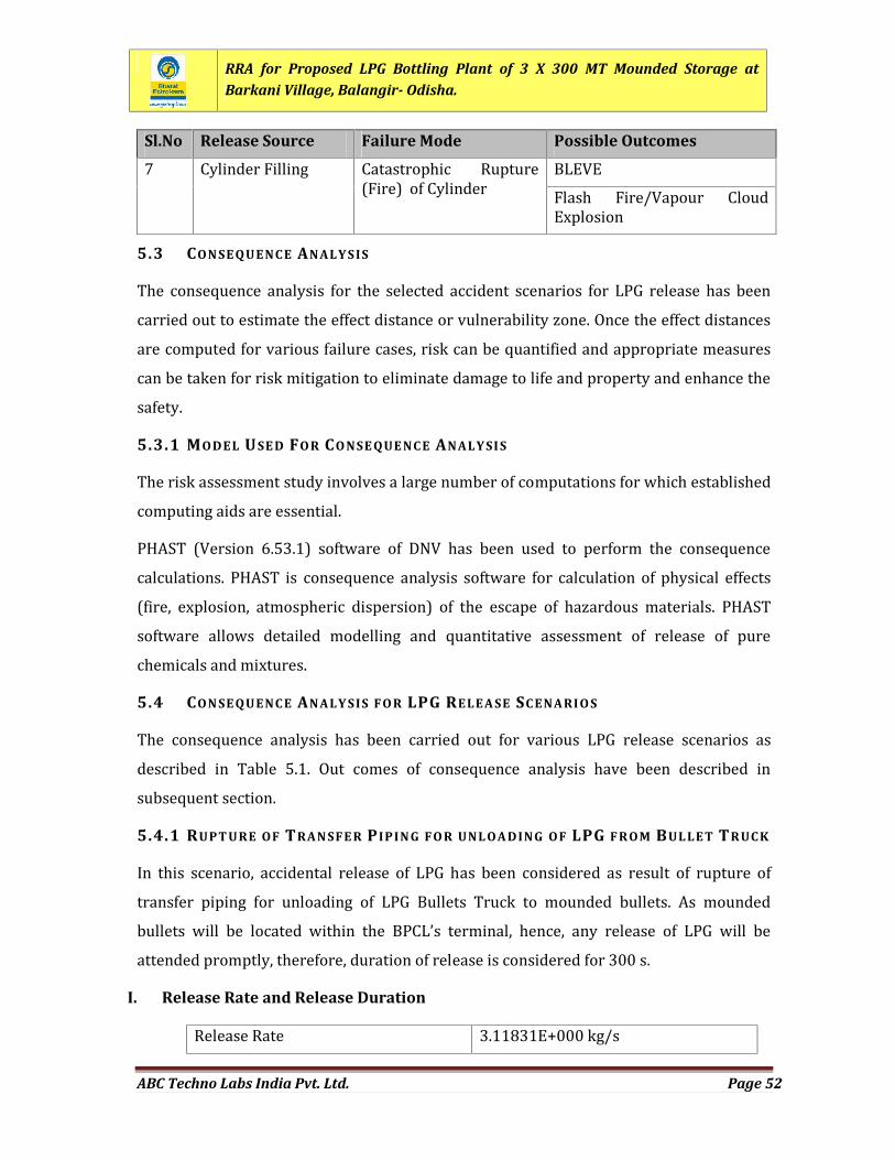
RRA for Proposed LPG Bottling Plant of 3 X 300 MT Mounded Storage atBarkani Village, Balangir- Odisha.
ABC Techno Labs India Pvt. Ltd. Page 52
Sl.No Release Source Failure Mode Possible Outcomes7 Cylinder Filling Catastrophic Rupture(Fire) of Cylinder BLEVEFlash Fire/Vapour CloudExplosion5.3 CON SE QUENC E ANALY SISThe consequence analysis for the selected accident scenarios for LPG release has beencarried out to estimate the effect distance or vulnerability zone. Once the effect distancesare computed for various failure cases, risk can be quantified and appropriate measurescan be taken for risk mitigation to eliminate damage to life and property and enhance thesafety.5.3.1 MODEL USE D FO R CO NSE QUE NC E ANALY SI SThe risk assessment study involves a large number of computations for which establishedcomputing aids are essential.PHAST (Version 6.53.1) software of DNV has been used to perform the consequencecalculations. PHAST is consequence analysis software for calculation of physical effects(fire, explosion, atmospheric dispersion) of the escape of hazardous materials. PHASTsoftware allows detailed modelling and quantitative assessment of release of purechemicals and mixtures.5.4 CON SE QUENC E ANALY SIS FO R LPG RELEA SE SC ENARI O SThe consequence analysis has been carried out for various LPG release scenarios asdescribed in Table 5.1. Out comes of consequence analysis have been described insubsequent section.5.4.1 RUPT URE OF TRAN SFE R P IPIN G FO R UNL OA DING OF LPG F R OM BUL LET TR UC KIn this scenario, accidental release of LPG has been considered as result of rupture oftransfer piping for unloading of LPG Bullets Truck to mounded bullets. As moundedbullets will be located within the BPCL’s terminal, hence, any release of LPG will beattended promptly, therefore, duration of release is considered for 300 s.
I. Release Rate and Release DurationRelease Rate 3.11831E+000 kg/s
RRA for Proposed LPG Bottling Plant of 3 X 300 MT Mounded Storage atBarkani Village, Balangir- Odisha.
ABC Techno Labs India Pvt. Ltd. Page 53
II. Jet Fire on Immediate IgnitionOn release of LPG in case of rupture of transfer line, jet fire will occur on immediateignition. Thermal radiation maximum distances from jet fire source are given below:Radiation Level
Thermal Radiation Level Distances (m)
B - 3 m/s D - 3 m/s E - 2 m/s37.5 kW/m2 Not Reached Not Reached Not Reached12.5 kW/m2 6.38437 6.38437 6.384374 kW/m2 23.661 23.661 23.661Thermal radiation intensity from jet fire is also presented in Figure 5.1.III. UFL and LFL Concentration DistancesIn the event of release of LPG due to rupture of bottom line, vapour cloud will be formed ifit is not getting source of ignition. LPG vapours under UFL and LFL concentration willoccur at following distances.UFL and LFL Concentration Distances
Concentration UFL and LFL Concentration Distances (m)B - 3 m/s D - 3 m/s E – 2 m/sUFL 0.06 0.057 0.051LEL 1.1041 1.06 1.061UFL and LFL Concentration HeightConcentration UFL and LFL Concentration Height (m)B - 3 m/s D - 3 m/s E – 2 m/sUFL 4.56 4.62 4.65LEL 11.97 12.27 12.47
IV. Flash Fire EnvelopeOn delayed ignition of LPG vapours within UFL and LFL, flash fire envelope will form asindicated below: Flash Fire Envelope (m) DistanceB - 3 m/s D - 3 m/s E - 2 m/s
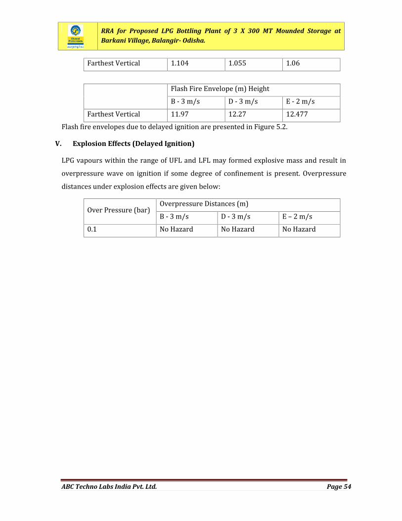
RRA for Proposed LPG Bottling Plant of 3 X 300 MT Mounded Storage atBarkani Village, Balangir- Odisha.
ABC Techno Labs India Pvt. Ltd. Page 54
Farthest Vertical 1.104 1.055 1.06Flash Fire Envelope (m) HeightB - 3 m/s D - 3 m/s E - 2 m/sFarthest Vertical 11.97 12.27 12.477Flash fire envelopes due to delayed ignition are presented in Figure 5.2.
V. Explosion Effects (Delayed Ignition)LPG vapours within the range of UFL and LFL may formed explosive mass and result inoverpressure wave on ignition if some degree of confinement is present. Overpressuredistances under explosion effects are given below:Over Pressure (bar) Overpressure Distances (m)B - 3 m/s D - 3 m/s E – 2 m/s0.1 No Hazard No Hazard No Hazard
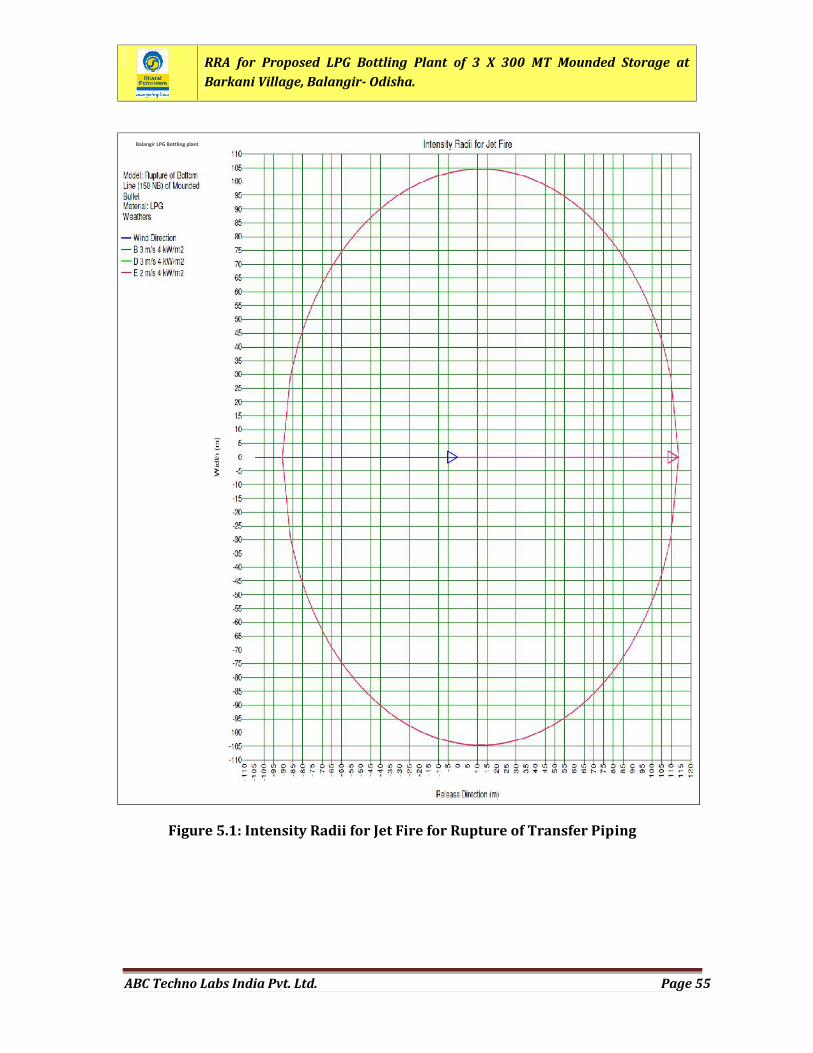
RRA for Proposed LPG Bottling Plant of 3 X 300 MT Mounded Storage atBarkani Village, Balangir- Odisha.
ABC Techno Labs India Pvt. Ltd. Page 55
Figure 5.1: Intensity Radii for Jet Fire for Rupture of Transfer Piping
Balangir LPG Bottling plant
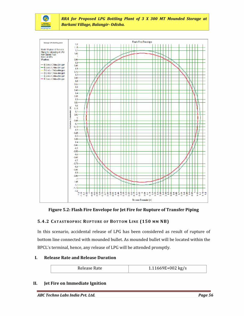
RRA for Proposed LPG Bottling Plant of 3 X 300 MT Mounded Storage atBarkani Village, Balangir- Odisha.
ABC Techno Labs India Pvt. Ltd. Page 56
5.4.2 CATAST ROP HIC RUPT URE OF BOTT OM LINE (150 MM NB)In this scenario, accidental release of LPG has been considered as result of rupture ofbottom line connected with mounded bullet. As mounded bullet will be located within theBPCL’s terminal, hence, any release of LPG will be attended promptly.I. Release Rate and Release DurationRelease Rate 1.11669E+002 kg/s
II. Jet Fire on Immediate Ignition
Figure 5.2: Flash Fire Envelope for Jet Fire for Rupture of Transfer Piping
Balangir LPG Bottling plant
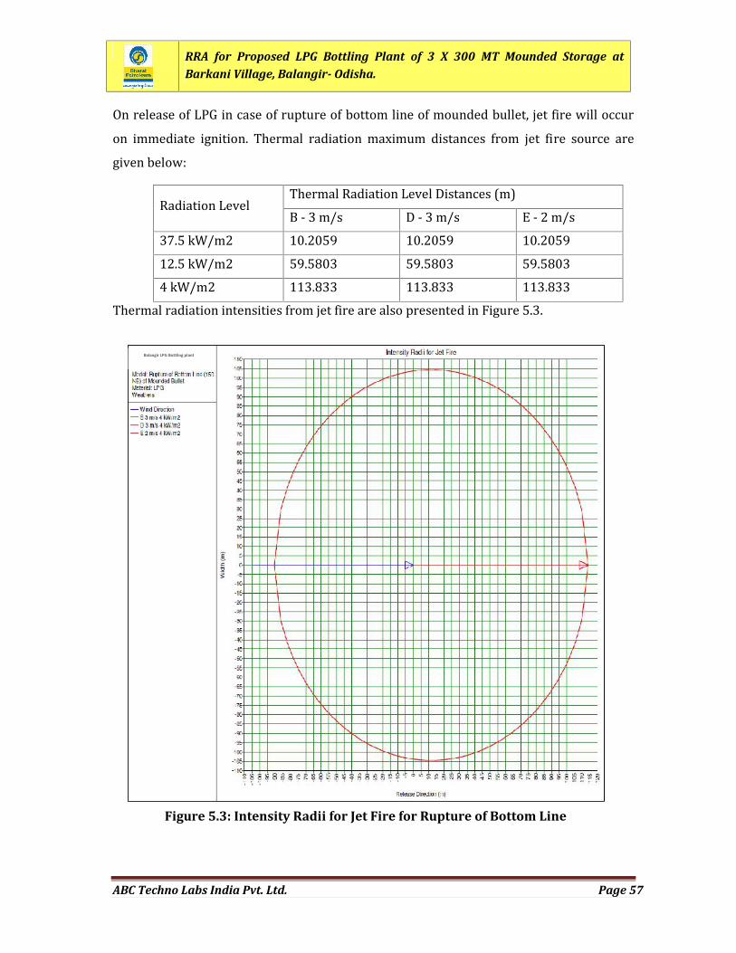
RRA for Proposed LPG Bottling Plant of 3 X 300 MT Mounded Storage atBarkani Village, Balangir- Odisha.
ABC Techno Labs India Pvt. Ltd. Page 57
On release of LPG in case of rupture of bottom line of mounded bullet, jet fire will occuron immediate ignition. Thermal radiation maximum distances from jet fire source aregiven below:Radiation Level Thermal Radiation Level Distances (m)B - 3 m/s D - 3 m/s E - 2 m/s37.5 kW/m2 10.2059 10.2059 10.205912.5 kW/m2 59.5803 59.5803 59.58034 kW/m2 113.833 113.833 113.833Thermal radiation intensities from jet fire are also presented in Figure 5.3.
Figure 5.3: Intensity Radii for Jet Fire for Rupture of Bottom Line
Balangir LPG Bottling plant
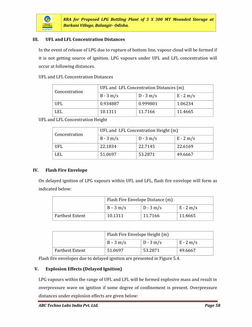
RRA for Proposed LPG Bottling Plant of 3 X 300 MT Mounded Storage atBarkani Village, Balangir- Odisha.
ABC Techno Labs India Pvt. Ltd. Page 58
III. UFL and LFL Concentration DistancesIn the event of release of LPG due to rupture of bottom line, vapour cloud will be formed ifit is not getting source of ignition. LPG vapours under UFL and LFL concentration willoccur at following distances.UFL and LFL Concentration DistancesConcentration UFL and LFL Concentration Distances (m)B - 3 m/s D - 3 m/s E - 2 m/sUFL 0.934887 0.999801 1.06234LEL 10.1311 11.7166 11.4665UFL and LFL Concentration HeightConcentration UFL and LFL Concentration Height (m)B - 3 m/s D - 3 m/s E - 2 m/sUFL 22.1834 22.7145 22.6169LEL 51.0697 53.2871 49.6667
IV. Flash Fire EnvelopeOn delayed ignition of LPG vapours within UFL and LFL, flash fire envelope will form asindicated below: Flash Fire Envelope Distance (m)B – 3 m/s D - 3 m/s E - 2 m/sFarthest Extent 10.1311 11.7166 11.4665Flash Fire Envelope Height (m)B – 3 m/s D - 3 m/s E - 2 m/sFarthest Extent 51.0697 53.2871 49.6667Flash fire envelopes due to delayed ignition are presented in Figure 5.4.
V. Explosion Effects (Delayed Ignition)LPG vapours within the range of UFL and LFL will be formed explosive mass and result inoverpressure wave on ignition if some degree of confinement is present. Overpressuredistances under explosion effects are given below:
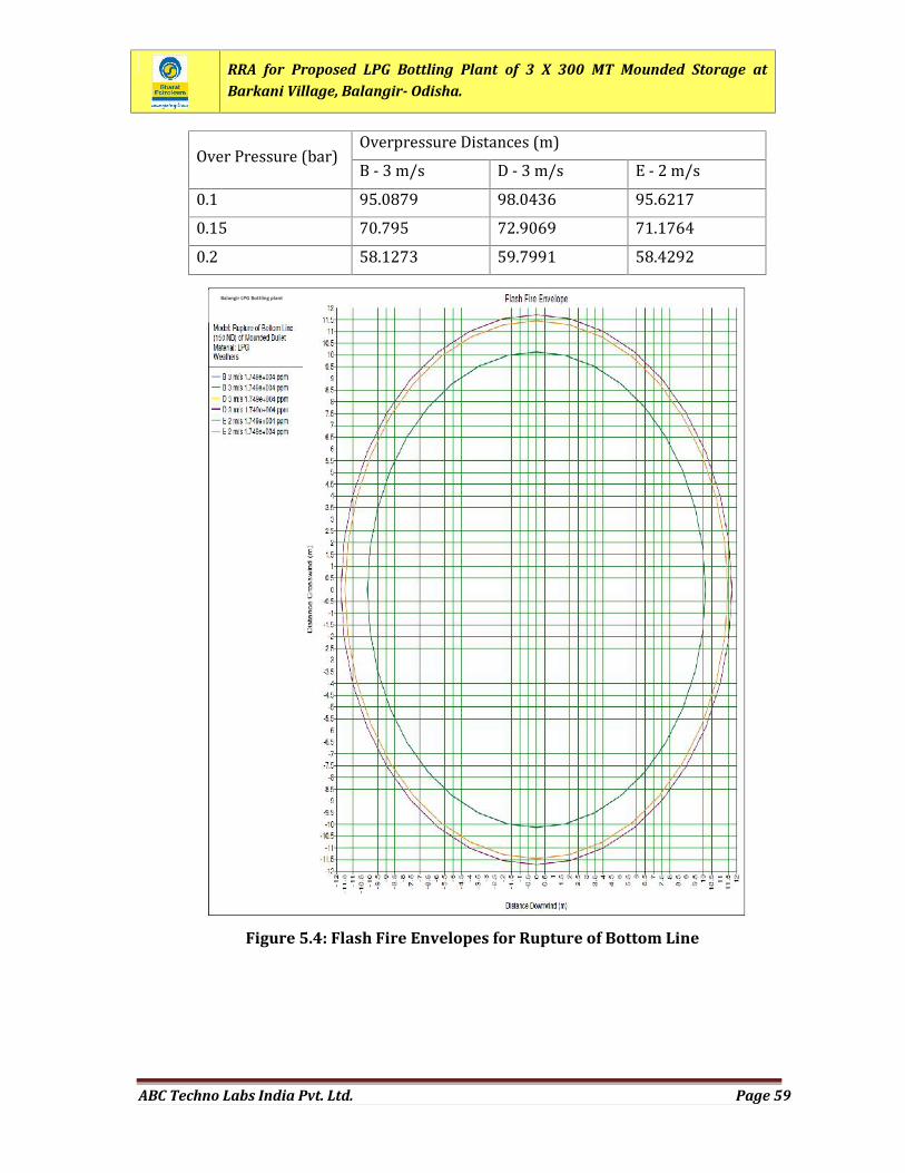
RRA for Proposed LPG Bottling Plant of 3 X 300 MT Mounded Storage atBarkani Village, Balangir- Odisha.
ABC Techno Labs India Pvt. Ltd. Page 59
Over Pressure (bar) Overpressure Distances (m)B - 3 m/s D - 3 m/s E - 2 m/s0.1 95.0879 98.0436 95.62170.15 70.795 72.9069 71.17640.2 58.1273 59.7991 58.4292
Figure 5.4: Flash Fire Envelopes for Rupture of Bottom Line
Balangir LPG Bottling plant
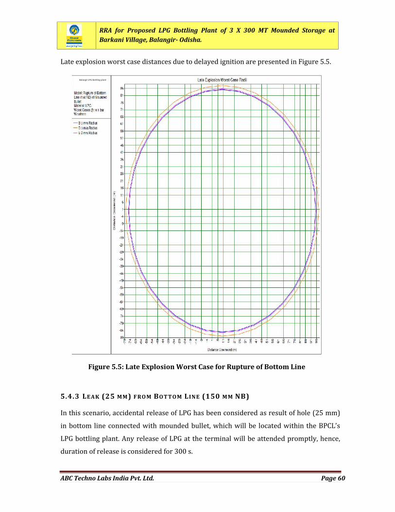
RRA for Proposed LPG Bottling Plant of 3 X 300 MT Mounded Storage atBarkani Village, Balangir- Odisha.
ABC Techno Labs India Pvt. Ltd. Page 60
Late explosion worst case distances due to delayed ignition are presented in Figure 5.5.
5.4.3 LEAK (25 MM) F RO M BOTTOM LINE (150 M M NB)In this scenario, accidental release of LPG has been considered as result of hole (25 mm)in bottom line connected with mounded bullet, which will be located within the BPCL’sLPG bottling plant. Any release of LPG at the terminal will be attended promptly, hence,duration of release is considered for 300 s.
Figure 5.5: Late Explosion Worst Case for Rupture of Bottom Line
Balangir LPG Bottling plant
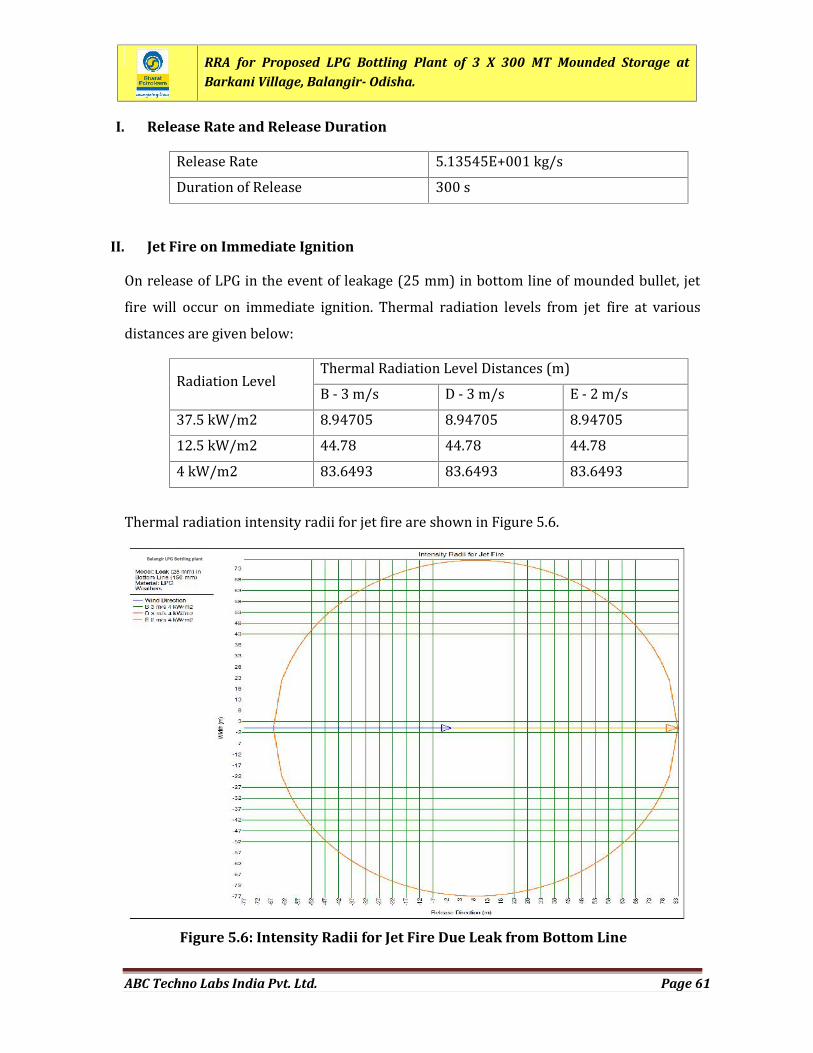
RRA for Proposed LPG Bottling Plant of 3 X 300 MT Mounded Storage atBarkani Village, Balangir- Odisha.
ABC Techno Labs India Pvt. Ltd. Page 61
I. Release Rate and Release DurationRelease Rate 5.13545E+001 kg/sDuration of Release 300 sII. Jet Fire on Immediate IgnitionOn release of LPG in the event of leakage (25 mm) in bottom line of mounded bullet, jetfire will occur on immediate ignition. Thermal radiation levels from jet fire at variousdistances are given below:
Radiation Level Thermal Radiation Level Distances (m)B - 3 m/s D - 3 m/s E - 2 m/s37.5 kW/m2 8.94705 8.94705 8.9470512.5 kW/m2 44.78 44.78 44.784 kW/m2 83.6493 83.6493 83.6493Thermal radiation intensity radii for jet fire are shown in Figure 5.6.
Figure 5.6: Intensity Radii for Jet Fire Due Leak from Bottom Line
Balangir LPG Bottling plant
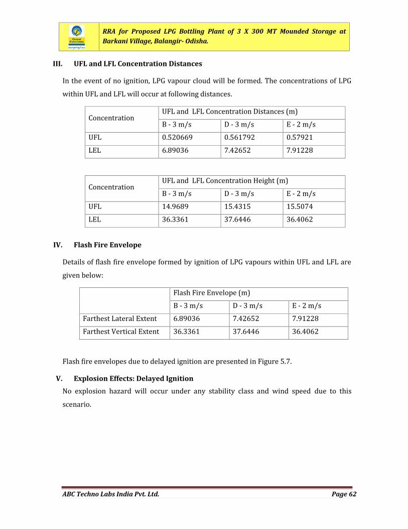
RRA for Proposed LPG Bottling Plant of 3 X 300 MT Mounded Storage atBarkani Village, Balangir- Odisha.
ABC Techno Labs India Pvt. Ltd. Page 62
III. UFL and LFL Concentration DistancesIn the event of no ignition, LPG vapour cloud will be formed. The concentrations of LPGwithin UFL and LFL will occur at following distances.Concentration UFL and LFL Concentration Distances (m)B - 3 m/s D - 3 m/s E - 2 m/sUFL 0.520669 0.561792 0.57921LEL 6.89036 7.42652 7.91228Concentration UFL and LFL Concentration Height (m)B - 3 m/s D - 3 m/s E - 2 m/sUFL 14.9689 15.4315 15.5074LEL 36.3361 37.6446 36.4062
IV. Flash Fire EnvelopeDetails of flash fire envelope formed by ignition of LPG vapours within UFL and LFL aregiven below: Flash Fire Envelope (m)B - 3 m/s D - 3 m/s E - 2 m/sFarthest Lateral Extent 6.89036 7.42652 7.91228Farthest Vertical Extent 36.3361 37.6446 36.4062Flash fire envelopes due to delayed ignition are presented in Figure 5.7.
V. Explosion Effects: Delayed IgnitionNo explosion hazard will occur under any stability class and wind speed due to thisscenario.
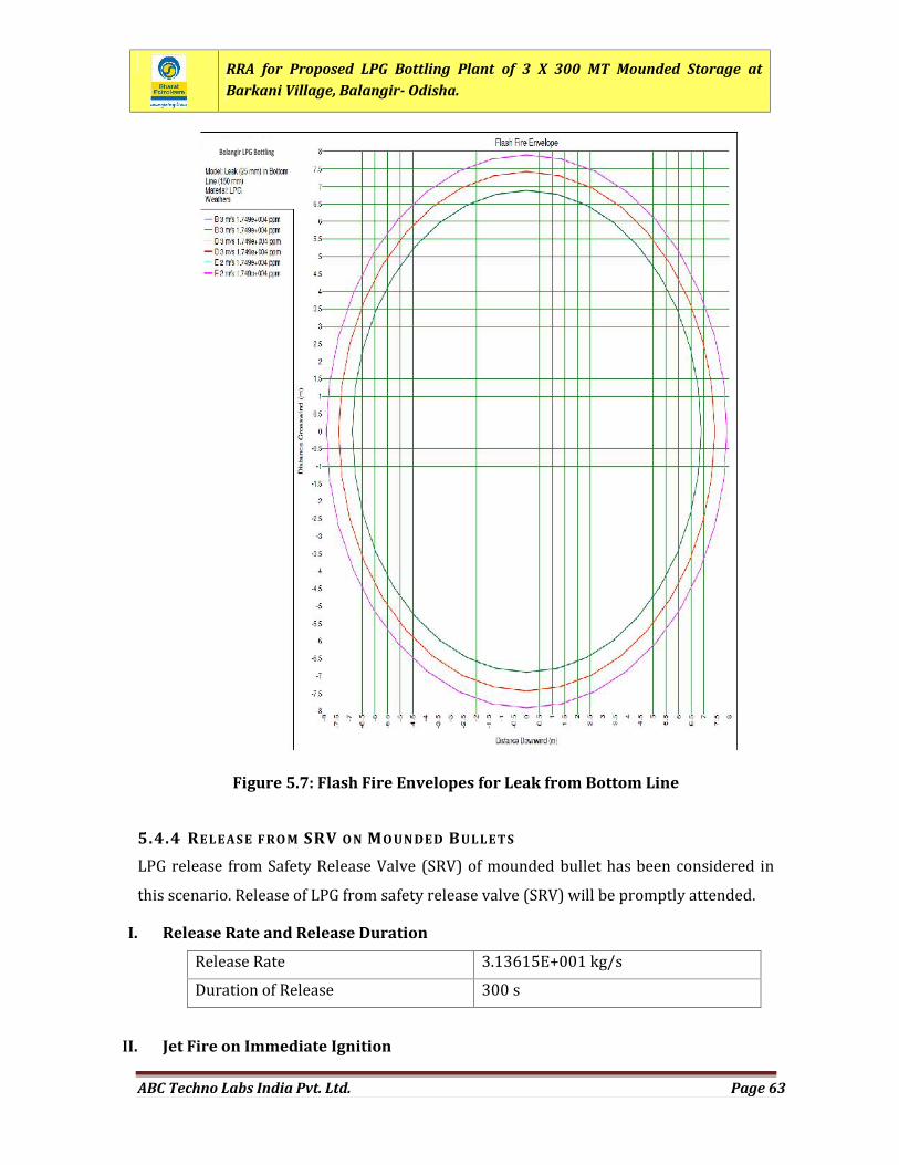
RRA for Proposed LPG Bottling Plant of 3 X 300 MT Mounded Storage atBarkani Village, Balangir- Odisha.
ABC Techno Labs India Pvt. Ltd. Page 63
Figure 5.7: Flash Fire Envelopes for Leak from Bottom Line
5.4.4 RELEASE F RO M SRV O N MO UN DE D BULLETSLPG release from Safety Release Valve (SRV) of mounded bullet has been considered inthis scenario. Release of LPG from safety release valve (SRV) will be promptly attended.I. Release Rate and Release DurationRelease Rate 3.13615E+001 kg/sDuration of Release 300 s
II. Jet Fire on Immediate Ignition
Bolangir LPG Bottlingplant
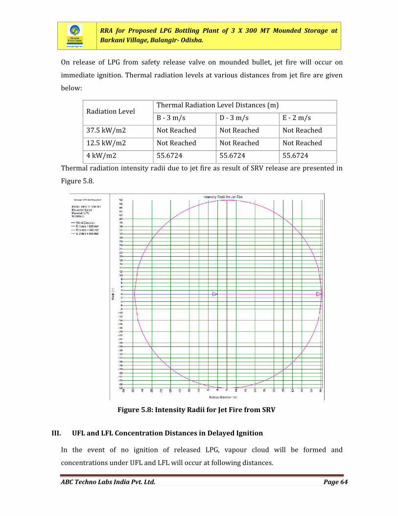
RRA for Proposed LPG Bottling Plant of 3 X 300 MT Mounded Storage atBarkani Village, Balangir- Odisha.
ABC Techno Labs India Pvt. Ltd. Page 64
On release of LPG from safety release valve on mounded bullet, jet fire will occur onimmediate ignition. Thermal radiation levels at various distances from jet fire are givenbelow:Radiation Level Thermal Radiation Level Distances (m)B - 3 m/s D - 3 m/s E - 2 m/s37.5 kW/m2 Not Reached Not Reached Not Reached12.5 kW/m2 Not Reached Not Reached Not Reached4 kW/m2 55.6724 55.6724 55.6724Thermal radiation intensity radii due to jet fire as result of SRV release are presented inFigure 5.8.
III. UFL and LFL Concentration Distances in Delayed IgnitionIn the event of no ignition of released LPG, vapour cloud will be formed andconcentrations under UFL and LFL will occur at following distances.
Figure 5.8: Intensity Radii for Jet Fire from SRV
Balangir LPG Bottling plant
RRA for Proposed LPG Bottling Plant of 3 X 300 MT Mounded Storage atBarkani Village, Balangir- Odisha.
ABC Techno Labs India Pvt. Ltd. Page 65
Concentration UFL and LFL Concentration Distances (m)B - 3 m/s D - 3 m/s E - 2 m/sUFL 0.176379 0.187458 0.189777LEL 2.82984 3.09822 3.22178Concentration UFL and LFL Concentration Height (m)B - 3 m/s D - 3 m/s E - 2 m/sUFL 13.1528 13.3668 13.3771LEL 30.9419 31.8459 31.0524
IV. Flash Fire EnvelopeOn ignition of concentration within in UFL and LFL, flash fire envelope will take place asper details given below: Flash Fire Envelope (m)B - 3 m/s D - 3 m/s E - 2 m/sFarthest Lateral Extent 2.82984 3.09822 3.22178Farthest Vertical Extent 30.9419 31.8459 31.0524Flash fire envelopes due to delayed ignition are presented in Figure 5.9.
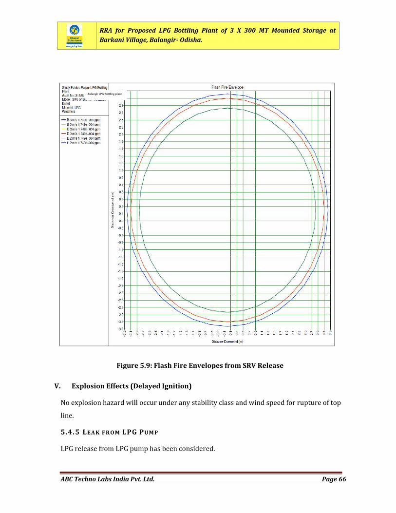
RRA for Proposed LPG Bottling Plant of 3 X 300 MT Mounded Storage atBarkani Village, Balangir- Odisha.
ABC Techno Labs India Pvt. Ltd. Page 66
V. Explosion Effects (Delayed Ignition)No explosion hazard will occur under any stability class and wind speed for rupture of topline.5.4.5 LEAK F R OM LPG PUM PLPG release from LPG pump has been considered.
Balangir LPG Bottling plant
Figure 5.9: Flash Fire Envelopes from SRV Release
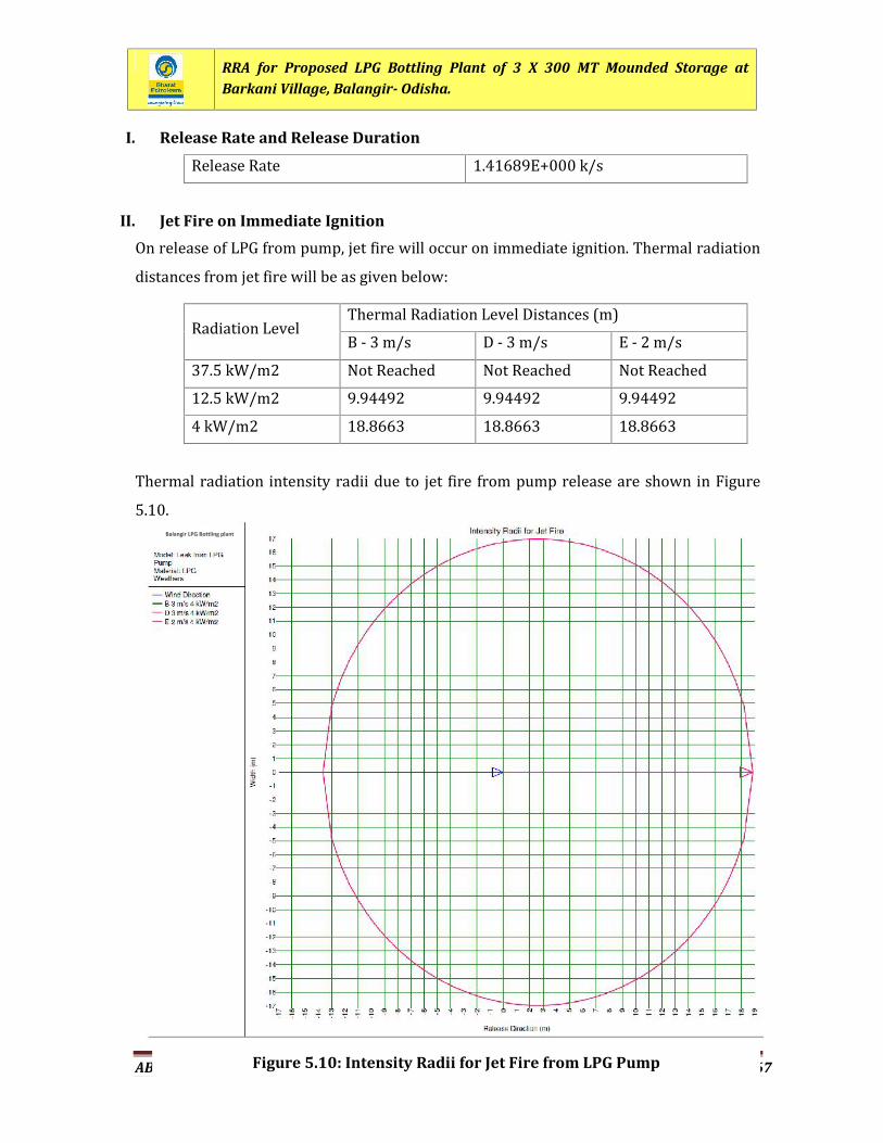
RRA for Proposed LPG Bottling Plant of 3 X 300 MT Mounded Storage atBarkani Village, Balangir- Odisha.
ABC Techno Labs India Pvt. Ltd. Page 67
I. Release Rate and Release DurationRelease Rate 1.41689E+000 k/sII. Jet Fire on Immediate IgnitionOn release of LPG from pump, jet fire will occur on immediate ignition. Thermal radiationdistances from jet fire will be as given below:
Radiation Level Thermal Radiation Level Distances (m)B - 3 m/s D - 3 m/s E - 2 m/s37.5 kW/m2 Not Reached Not Reached Not Reached12.5 kW/m2 9.94492 9.94492 9.944924 kW/m2 18.8663 18.8663 18.8663Thermal radiation intensity radii due to jet fire from pump release are shown in Figure5.10.
Figure 5.10: Intensity Radii for Jet Fire from LPG Pump
Balangir LPG Bottling plant
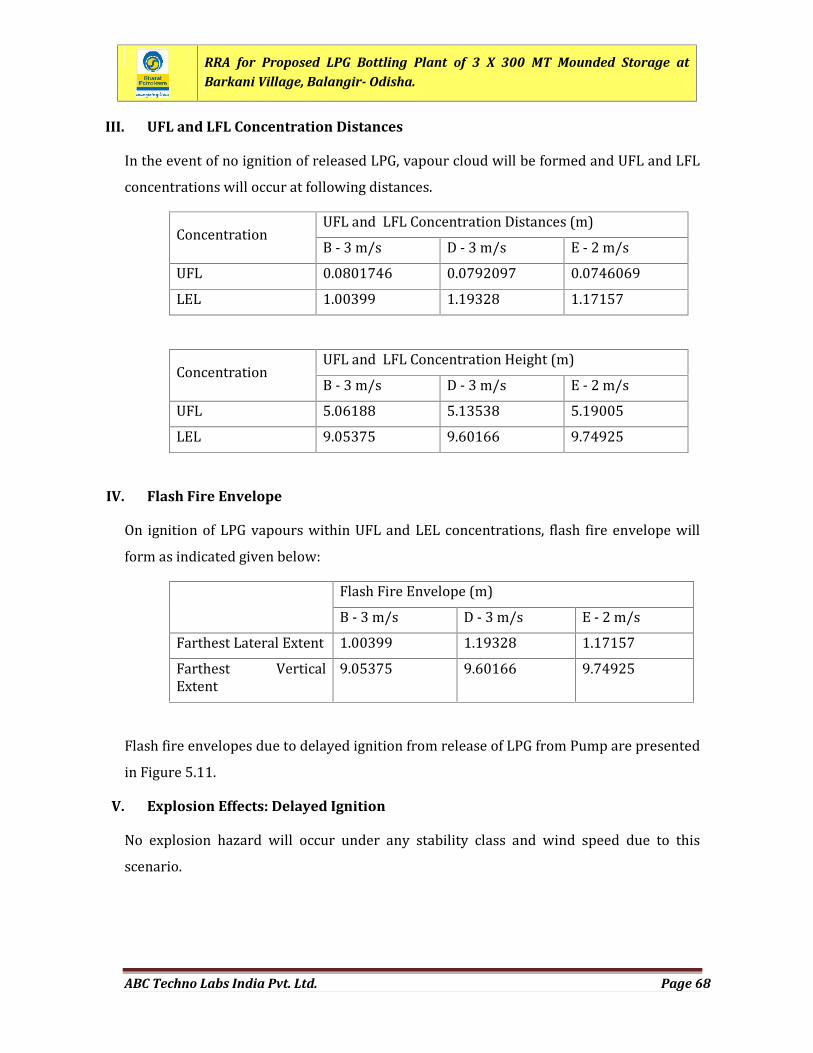
RRA for Proposed LPG Bottling Plant of 3 X 300 MT Mounded Storage atBarkani Village, Balangir- Odisha.
ABC Techno Labs India Pvt. Ltd. Page 68
III. UFL and LFL Concentration DistancesIn the event of no ignition of released LPG, vapour cloud will be formed and UFL and LFLconcentrations will occur at following distances.Concentration UFL and LFL Concentration Distances (m)B - 3 m/s D - 3 m/s E - 2 m/sUFL 0.0801746 0.0792097 0.0746069LEL 1.00399 1.19328 1.17157Concentration UFL and LFL Concentration Height (m)B - 3 m/s D - 3 m/s E - 2 m/sUFL 5.06188 5.13538 5.19005LEL 9.05375 9.60166 9.74925
IV. Flash Fire EnvelopeOn ignition of LPG vapours within UFL and LEL concentrations, flash fire envelope willform as indicated given below: Flash Fire Envelope (m)B - 3 m/s D - 3 m/s E - 2 m/sFarthest Lateral Extent 1.00399 1.19328 1.17157Farthest VerticalExtent 9.05375 9.60166 9.74925Flash fire envelopes due to delayed ignition from release of LPG from Pump are presentedin Figure 5.11.
V. Explosion Effects: Delayed IgnitionNo explosion hazard will occur under any stability class and wind speed due to thisscenario.
RRA for Proposed LPG Bottling Plant of 3 X 300 MT Mounded Storage atBarkani Village, Balangir- Odisha.
ABC Techno Labs India Pvt. Ltd. Page 69
5.4.6 LEAK F R OM LPG COM PRE SSO RLPG release from LPG compressor has been considered.I. Release Rate and Release DurationRelease Rate 3.71579E+000 k/s
Figure 5.11: Flash Fire Envelopes from LPG Pump
Balangir LPG Bottling plant
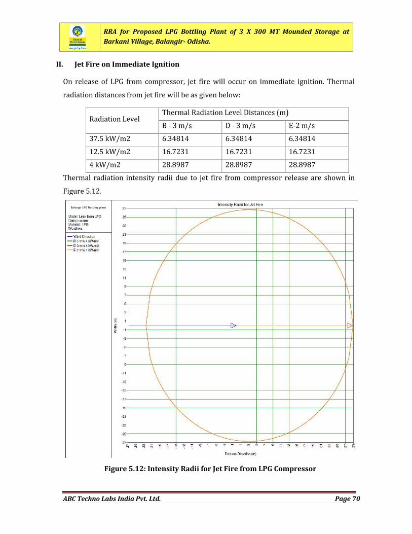
RRA for Proposed LPG Bottling Plant of 3 X 300 MT Mounded Storage atBarkani Village, Balangir- Odisha.
ABC Techno Labs India Pvt. Ltd. Page 70
II. Jet Fire on Immediate IgnitionOn release of LPG from compressor, jet fire will occur on immediate ignition. Thermalradiation distances from jet fire will be as given below:Radiation Level Thermal Radiation Level Distances (m)B - 3 m/s D - 3 m/s E-2 m/s37.5 kW/m2 6.34814 6.34814 6.3481412.5 kW/m2 16.7231 16.7231 16.72314 kW/m2 28.8987 28.8987 28.8987Thermal radiation intensity radii due to jet fire from compressor release are shown inFigure 5.12.
Figure 5.12: Intensity Radii for Jet Fire from LPG Compressor
Balangir LPG Bottling plant
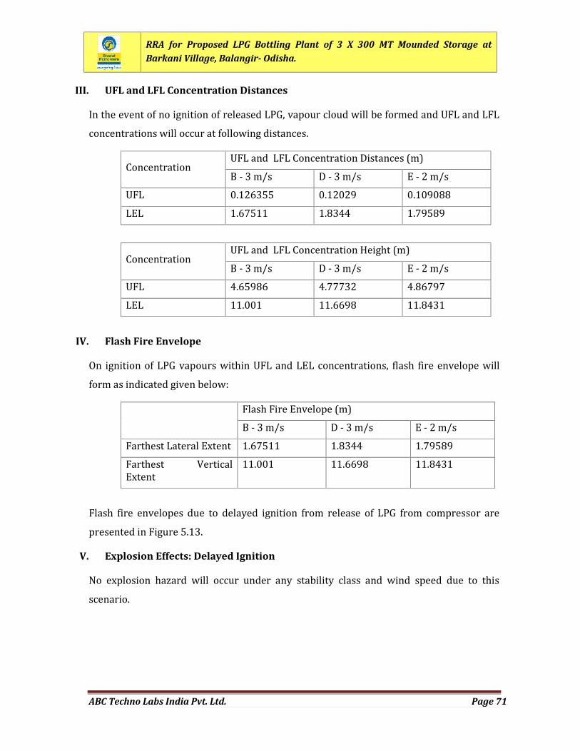
RRA for Proposed LPG Bottling Plant of 3 X 300 MT Mounded Storage atBarkani Village, Balangir- Odisha.
ABC Techno Labs India Pvt. Ltd. Page 71
III. UFL and LFL Concentration DistancesIn the event of no ignition of released LPG, vapour cloud will be formed and UFL and LFLconcentrations will occur at following distances.Concentration UFL and LFL Concentration Distances (m)B - 3 m/s D - 3 m/s E - 2 m/sUFL 0.126355 0.12029 0.109088LEL 1.67511 1.8344 1.79589Concentration UFL and LFL Concentration Height (m)B - 3 m/s D - 3 m/s E - 2 m/sUFL 4.65986 4.77732 4.86797LEL 11.001 11.6698 11.8431
IV. Flash Fire EnvelopeOn ignition of LPG vapours within UFL and LEL concentrations, flash fire envelope willform as indicated given below: Flash Fire Envelope (m)B - 3 m/s D - 3 m/s E - 2 m/sFarthest Lateral Extent 1.67511 1.8344 1.79589Farthest VerticalExtent 11.001 11.6698 11.8431Flash fire envelopes due to delayed ignition from release of LPG from compressor arepresented in Figure 5.13.
V. Explosion Effects: Delayed IgnitionNo explosion hazard will occur under any stability class and wind speed due to thisscenario.
RRA for Proposed LPG Bottling Plant of 3 X 300 MT Mounded Storage atBarkani Village, Balangir- Odisha.
ABC Techno Labs India Pvt. Ltd. Page 72
5.4.7 CATAST ROP HIC RUPT URE OF LPG BULLET TR UC K (18 MT)At the LPG bottling plant, LPG will be transported by Bullet Truck tank. In the event of firein LPG bullet truck in parking area, BLEVE may be occurred and fireball will result as outcome.I. Release Rate and Release DurationRelease Rate Release rate is not applicable as under BLEVE, total Inventory
Figure 5.13: Flash Fire Envelopes from LPG Compressor
Balangir LPG Bottling plant
RRA for Proposed LPG Bottling Plant of 3 X 300 MT Mounded Storage atBarkani Village, Balangir- Odisha.
ABC Techno Labs India Pvt. Ltd. Page 73
of LPG will result in Fireball.II. Fireball Hazard as a Result of BLEVECatastrophic rupture of LPG bullet truck followed by immediate ignition will result inoccurrence of BLEVE. As outcome of BLEVE, fireball will outcome as per details givenbelow: Fireball Radius 78.25 mFireball Duration 10.88 sFlame Emissive Power 301.23 kW/m2Fireball Lift Off Height 156.51m
III. Thermal Radiation Effect From Fireball EllipseThermal radiation levels at various distances from fireball ellipse are given below:Radiation Level Thermal Radiation Level Distances (m)B - 3 m/s D - 3 m/s E - 2 m/s37.5 kW/m2 87.0976 87.0976 87.097612.5 kW/m2 246.098 246.098 246.0984 kW/m2 461.432 461.432 461.432
Thermal radiation intensity radii due to fireball ellipse are shown in Figure 5.14.
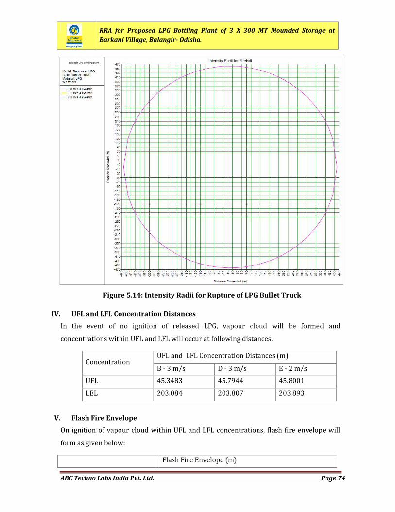
RRA for Proposed LPG Bottling Plant of 3 X 300 MT Mounded Storage atBarkani Village, Balangir- Odisha.
ABC Techno Labs India Pvt. Ltd. Page 74
IV. UFL and LFL Concentration DistancesIn the event of no ignition of released LPG, vapour cloud will be formed andconcentrations within UFL and LFL will occur at following distances.Concentration UFL and LFL Concentration Distances (m)B - 3 m/s D - 3 m/s E - 2 m/sUFL 45.3483 45.7944 45.8001LEL 203.084 203.807 203.893
V. Flash Fire EnvelopeOn ignition of vapour cloud within UFL and LFL concentrations, flash fire envelope willform as given below: Flash Fire Envelope (m)
Figure 5.14: Intensity Radii for Rupture of LPG Bullet Truck
Balangir LPG Bottling plant
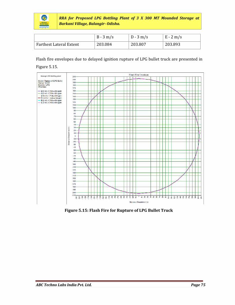
RRA for Proposed LPG Bottling Plant of 3 X 300 MT Mounded Storage atBarkani Village, Balangir- Odisha.
ABC Techno Labs India Pvt. Ltd. Page 75
B - 3 m/s D - 3 m/s E - 2 m/sFarthest Lateral Extent 203.084 203.807 203.893Flash fire envelopes due to delayed ignition rupture of LPG bullet truck are presented inFigure 5.15.
Figure 5.15: Flash Fire for Rupture of LPG Bullet Truck
Balangir LPG Bottling plant
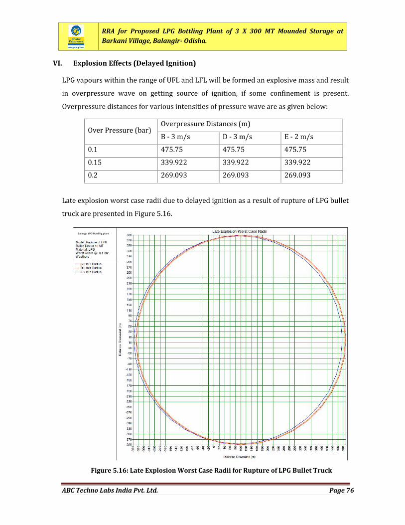
RRA for Proposed LPG Bottling Plant of 3 X 300 MT Mounded Storage atBarkani Village, Balangir- Odisha.
ABC Techno Labs India Pvt. Ltd. Page 76
VI. Explosion Effects (Delayed Ignition)LPG vapours within the range of UFL and LFL will be formed an explosive mass and resultin overpressure wave on getting source of ignition, if some confinement is present.Overpressure distances for various intensities of pressure wave are as given below:Over Pressure (bar) Overpressure Distances (m)B - 3 m/s D - 3 m/s E - 2 m/s0.1 475.75 475.75 475.750.15 339.922 339.922 339.9220.2 269.093 269.093 269.093
Late explosion worst case radii due to delayed ignition as a result of rupture of LPG bullettruck are presented in Figure 5.16.
Figure 5.16: Late Explosion Worst Case Radii for Rupture of LPG Bullet Truck
Balangir LPG Bottling plant
RRA for Proposed LPG Bottling Plant of 3 X 300 MT Mounded Storage atBarkani Village, Balangir- Odisha.
ABC Techno Labs India Pvt. Ltd. Page 77
5.4.8 CATAST ROP HIC RUPT URE OF LPG CYLIN DE RAt the LPG bottling plant, Cylinders will be filled with LPG. In the event of fire in LPGcylinder, BLEVE may be occurred and fireball will result as out come.I. Release Rate and Release DurationRelease Rate Release rate is not applicable as under BLEVE, total Inventoryof LPG will result in Fireball.
II. Fireball Hazard as a Result of BLEVECatastrophic rupture of LPG cylinder followed by immediate ignition will result inoccurrence of BLEVE. As outcome of BLEVE, fireball will outcome as per details givenbelow: Fireball Radius 7.67 mFireball Duration 1.70 sFlame Emissive Power 150.12 kW/m2Fireball Lift Off Height 15.351mIII. Thermal Radiation Effect from Fireball EllipseThermal radiation levels at various distances from fireball ellipse are given below:
Radiation Level Thermal Radiation Level Distances (m)B - 3 m/s D - 3 m/s E - 2 m/s37.5 kW/m2 4.39453 4.39453 4.3945312.5 kW/m2 19.3709 19.3709 19.37094 kW/m2 37.9695 37.9695 37.9695Thermal radiation intensity radii due to fireball ellipse of LPG Cylinder are shown inFigure 5.17.
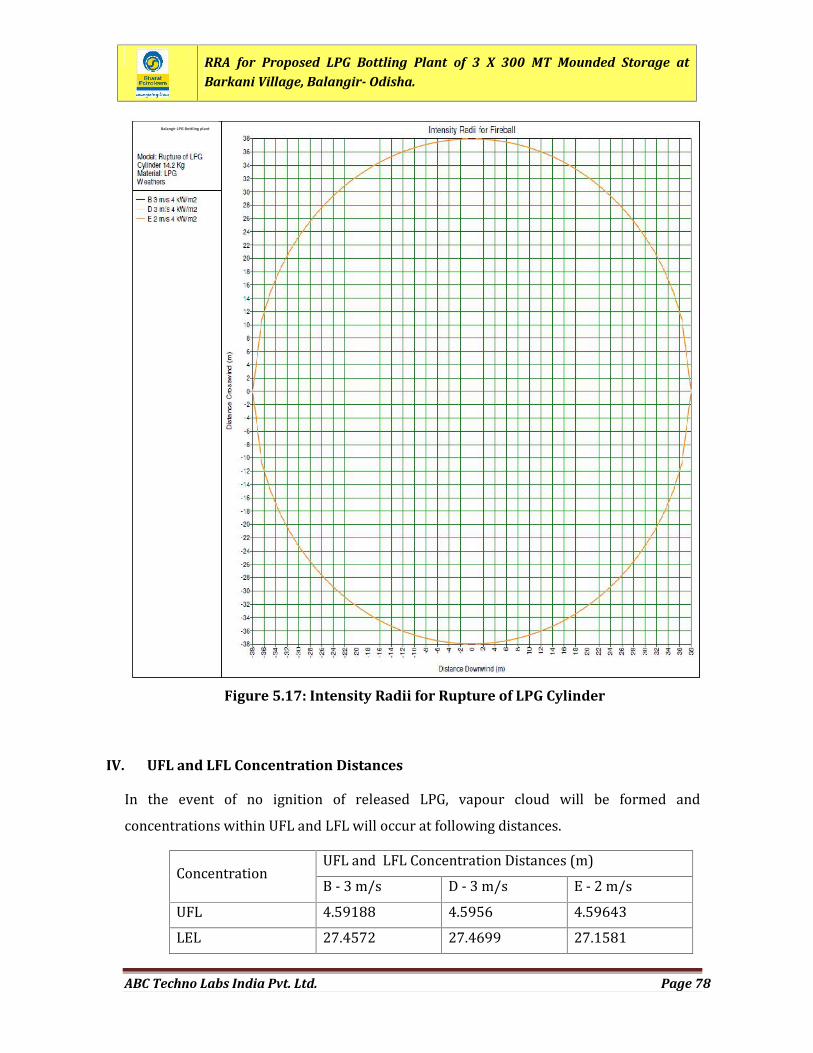
RRA for Proposed LPG Bottling Plant of 3 X 300 MT Mounded Storage atBarkani Village, Balangir- Odisha.
ABC Techno Labs India Pvt. Ltd. Page 78
IV. UFL and LFL Concentration DistancesIn the event of no ignition of released LPG, vapour cloud will be formed andconcentrations within UFL and LFL will occur at following distances.Concentration UFL and LFL Concentration Distances (m)B - 3 m/s D - 3 m/s E - 2 m/sUFL 4.59188 4.5956 4.59643LEL 27.4572 27.4699 27.1581
Figure 5.17: Intensity Radii for Rupture of LPG Cylinder
Balangir LPG Bottling plant
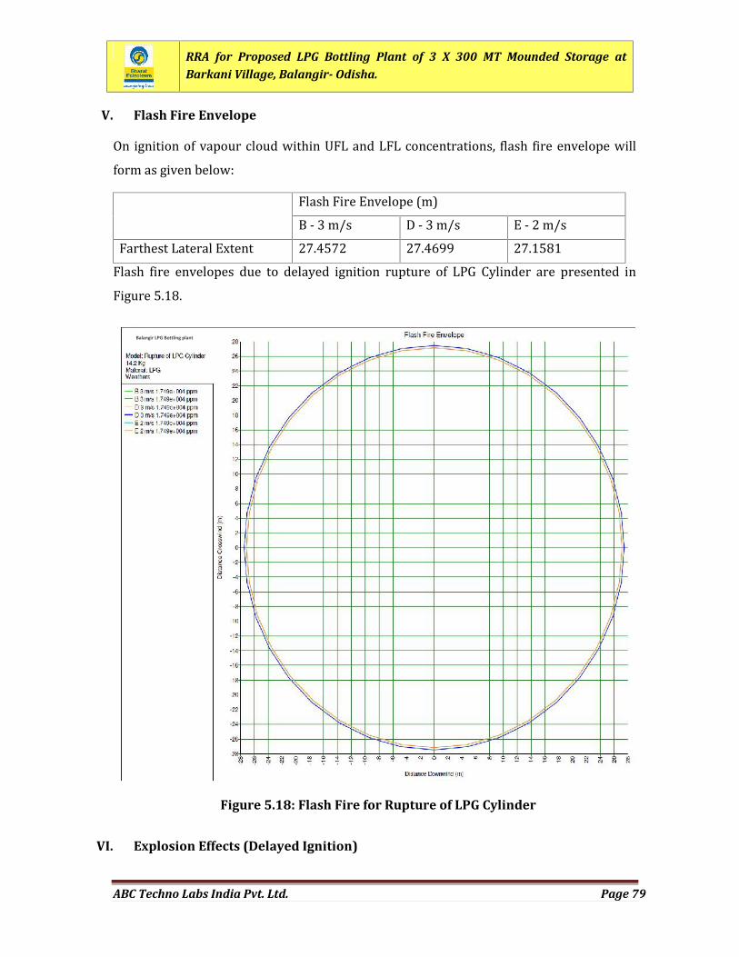
RRA for Proposed LPG Bottling Plant of 3 X 300 MT Mounded Storage atBarkani Village, Balangir- Odisha.
ABC Techno Labs India Pvt. Ltd. Page 79
V. Flash Fire EnvelopeOn ignition of vapour cloud within UFL and LFL concentrations, flash fire envelope willform as given below: Flash Fire Envelope (m)B - 3 m/s D - 3 m/s E - 2 m/sFarthest Lateral Extent 27.4572 27.4699 27.1581Flash fire envelopes due to delayed ignition rupture of LPG Cylinder are presented inFigure 5.18.
VI. Explosion Effects (Delayed Ignition)
Figure 5.18: Flash Fire for Rupture of LPG Cylinder
Balangir LPG Bottling plant
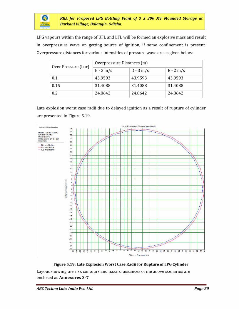
RRA for Proposed LPG Bottling Plant of 3 X 300 MT Mounded Storage atBarkani Village, Balangir- Odisha.
ABC Techno Labs India Pvt. Ltd. Page 80
LPG vapours within the range of UFL and LFL will be formed an explosive mass and resultin overpressure wave on getting source of ignition, if some confinement is present.Overpressure distances for various intensities of pressure wave are as given below:Over Pressure (bar) Overpressure Distances (m)B - 3 m/s D - 3 m/s E - 2 m/s0.1 43.9593 43.9593 43.95930.15 31.4088 31.4088 31.40880.2 24.8642 24.8642 24.8642
Late explosion worst case radii due to delayed ignition as a result of rupture of cylinderare presented in Figure 5.19.
Layout showing the risk contours and hazard distances of the above scenarios areenclosed as Annexures 3-7
Figure 5.19: Late Explosion Worst Case Radii for Rupture of LPG Cylinder
Balangir LPG Bottling plant
RRA for Proposed LPG Bottling Plant of 3 X 300 MT Mounded Storage atBarkani Village, Balangir- Odisha.
ABC Techno Labs India Pvt. Ltd. Page 81
CHAPTER 6
FREQUENCY ANALYSIS
RRA for Proposed LPG Bottling Plant of 3 X 300 MT Mounded Storage atBarkani Village, Balangir- Odisha.
ABC Techno Labs India Pvt. Ltd. Page 82
CHAPTER 6: FREQUENCY ANALYSIS
6.1 PREAM BLEThe failure frequency analysis aims at estimation of the “probability” of the incident.Failure frequencies may be classified as generic and synthesised for a particular situation,especially for more complex systems. Generic failure frequencies are preferred whereveravailable, as these reduce variances arising out of analyst judgement in the failurefrequency estimation. Fault trees make use of generic failure frequencies of componentsfor a system or its subsystems to conclude the overall probability of failure.The standard method of calculating the failure rate of an isolated section of an equipmentor a chosen set of equipment items is to count the different items and associated linelengths. The failure rate for a certain item is then broken down into the correctproportions for required release rate bands. The overall frequency for a particular set ofequipment is then:Ft = F N
Where: Ft = total failure frequency/per year/per unit
F = individual item frequency/per year
N = number of items or length of piping unit
6.2 FAILURE FREQ UENC Y DATA BA SEAn incident frequency can be derived from internationally well known generic databasesincase the design is sufficiently similar to facilities represented in the historical failurerecords. There are several accepted sources of international failure rate data forunderground pipelines, which include CONCAWE (Conservation of Clean Air and Water inEurope), European Oil and Product Lines, US Gas Transmission Lines, UK OnshorePipeline Operators’ Association (UKOPA), International Association of Oil and GasProducers (OGP) data base, TNO data base and others.The generic failure data base selected for calculating the failure frequencies was the UKOnshore Pipelines Operators’ Association (UKOPA) database. UK OPA report (No: 6957
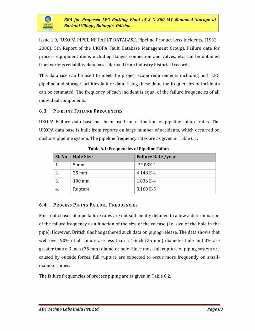
RRA for Proposed LPG Bottling Plant of 3 X 300 MT Mounded Storage atBarkani Village, Balangir- Odisha.
ABC Techno Labs India Pvt. Ltd. Page 83
Issue 1.0, “UKOPA PIPELINE FAULT DATABASE, Pipeline Product Loss Incidents, (1962 -2006), 5th Report of the UKOPA Fault Database Management Group). Failure data forprocess equipment items including flanges connection and valves, etc. can be obtainedfrom various reliability data bases derived from industry historical records.This database can be used to meet the project scope requirements including both LPGpipeline and storage facilities failure data. Using these data, the frequencies of incidentscan be estimated. The frequency of each incident is equal of the failure frequencies of allindividual components.6.3 P IPELINE FAIL URE FR EQUE NC IESUKOPA Failure data base has been used for estimation of pipeline failure rates. TheUKOPA data base is built from reports on large number of accidents, which occurred ononshore pipeline system. The pipeline frequency rates are as given in Table 6.1.
Table 6.1: Frequencies of Pipeline Failure
Sl. No Hole Size Failure Rate /year1. 5 mm 7.208E-42. 25 mm 4.148 E-43. 100 mm 1.836 E-44. Rupture 8.160 E-56.4 PROC E SS P IPIN G FAIL URE FREQ UENC IE SMost data bases of pipe failure rates are not sufficiently detailed to allow a determinationof the failure frequency as a function of the size of the release (i.e. size of the hole in thepipe). However, British Gas has gathered such data on piping release. The data shows thatwell over 90% of all failure are less than a 1-inch (25 mm) diameter hole and 3% aregreater than a 3 inch (75 mm) diameter hole. Since most full rupture of piping system arecaused by outside forces, full rupture are expected to occur more frequently on small-diameter pipes.The failure frequencies of process piping are as given in Table 6.2.
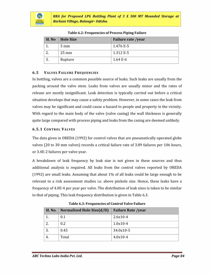
RRA for Proposed LPG Bottling Plant of 3 X 300 MT Mounded Storage atBarkani Village, Balangir- Odisha.
ABC Techno Labs India Pvt. Ltd. Page 84
Table 6.2: Frequencies of Process Piping Failure
Sl. No Hole Size Failure rate /year1. 5 mm 1.476 E-52. 25 mm 1.312 E-53. Rupture 1.64 E-66.5 VALVES FAIL URE FRE QUENC IE SIn bottling, valves are a common possible source of leaks. Such leaks are usually from thepacking around the valve stem. Leaks from valves are usually minor and the rates ofrelease are mostly insignificant. Leak detection is typically carried out before a criticalsituation develops that may cause a safety problem. However, in some cases the leak fromvalves may be significant and could cause a hazard to people and property in the vicinity.With regard to the main body of the valve (valve casing) the wall thickness is generallyquite large compared with process piping and leaks from the casing are deemed unlikely.6.5.1 CONT ROL VALVE SThe data given in OREDA (1992) for control valves that are pneumatically operated globevalves (20 to 30 mm valves) records a critical failure rate of 3.89 failures per 106 hours,or 3.4E-2 failures per valve-year.A breakdown of leak frequency by leak size is not given in these sources and thusadditional analysis is required. All leaks from the control valves reported by OREDA(1992) are small leaks. Assuming that about 1% of all leaks could be large enough to berelevant to a risk assessment studies i.e. above pinhole size. Hence, these leaks have afrequency of 4.0E-4 per year per valve. The distribution of leak sizes is taken to be similarto that of piping. This leak frequency distribution is given in Table 6.3.
Table 6.3: Frequencies of Control Valve Failure
Sl. No. Normalized Hole Size(d/D) Failure Rate /year1. 0.1 2.6x10-42. 0.2 1.0x10-43. 0.45 34.0x10-54. Total 4.0x10⁻⁴
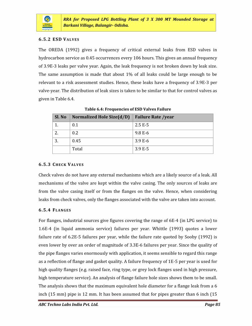
RRA for Proposed LPG Bottling Plant of 3 X 300 MT Mounded Storage atBarkani Village, Balangir- Odisha.
ABC Techno Labs India Pvt. Ltd. Page 85
6.5.2 ESD VAL VE SThe OREDA (1992) gives a frequency of critical external leaks from ESD valves inhydrocarbon service as 0.45 occurrences every 106 hours. This gives an annual frequencyof 3.9E-3 leaks per valve year. Again, the leak frequency is not broken down by leak size.The same assumption is made that about 1% of all leaks could be large enough to berelevant to a risk assessment studies. Hence, these leaks have a frequency of 3.9E-3 pervalve-year. The distribution of leak sizes is taken to be similar to that for control valves asgiven in Table 6.4.Table 6.4: Frequencies of ESD Valves Failure
Sl. No Normalized Hole Size(d/D) Failure Rate /year1. 0.1 2.5 E-52. 0.2 9.8 E-63. 0.45 3.9 E-6Total 3.9 E-56.5.3 CHEC K VALVE SCheck valves do not have any external mechanisms which are a likely source of a leak. Allmechanisms of the valve are kept within the valve casing. The only sources of leaks arefrom the valve casing itself or from the flanges on the valve. Hence, when consideringleaks from check valves, only the flanges associated with the valve are taken into account.6.5.4 FLANGE SFor flanges, industrial sources give figures covering the range of 6E-4 (in LPG service) to1.6E-4 (in liquid ammonia service) failures per year. Whittle (1993) quotes a lowerfailure rate of 6.2E-5 failures per year, while the failure rate quoted by Sooby (1992) iseven lower by over an order of magnitude of 3.3E-6 failures per year. Since the quality ofthe pipe flanges varies enormously with application, it seems sensible to regard this rangeas a reflection of flange and gasket quality. A failure frequency of 1E-5 per year is used forhigh quality flanges (e.g. raised face, ring type, or grey lock flanges used in high pressure,high temperature service). An analysis of flange failure hole sizes shows them to be small.The analysis shows that the maximum equivalent hole diameter for a flange leak from a 6inch (15 mm) pipe is 12 mm. It has been assumed that for pipes greater than 6 inch (15
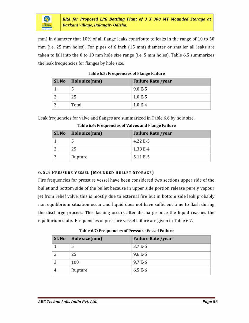
RRA for Proposed LPG Bottling Plant of 3 X 300 MT Mounded Storage atBarkani Village, Balangir- Odisha.
ABC Techno Labs India Pvt. Ltd. Page 86
mm) in diameter that 10% of all flange leaks contribute to leaks in the range of 10 to 50mm (i.e. 25 mm holes). For pipes of 6 inch (15 mm) diameter or smaller all leaks aretaken to fall into the 0 to 10 mm hole size range (i.e. 5 mm holes). Table 6.5 summarizesthe leak frequencies for flanges by hole size.Table 6.5: Frequencies of Flange Failure
Sl. No Hole size(mm) Failure Rate /year1. 5 9.0 E-52. 25 1.0 E-53. Total 1.0 E-4Leak frequencies for valve and flanges are summarized in Table 6.6 by hole size.
Table 6.6: Frequencies of Valves and Flange Failure
Sl. No Hole size(mm) Failure Rate /year1. 5 4.22 E-52. 25 1.38 E-43. Rupture 5.11 E-56.5.5 PRESSURE VE SSEL (MOUN DE D BULLET STO R AGE )Fire frequencies for pressure vessel have been considered two sections upper side of thebullet and bottom side of the bullet because in upper side portion release purely vapourjet from relief valve, this is mostly due to external fire but in bottom side leak probablynon equilibrium situation occur and liquid does not have sufficient time to flash duringthe discharge process. The flashing occurs after discharge once the liquid reaches theequilibrium state. Frequencies of pressure vessel failure are given in Table 6.7.
Table 6.7: Frequencies of Pressure Vessel Failure
Sl. No Hole size(mm) Failure Rate /year1. 5 3.7 E-52. 25 9.6 E-53. 100 9.7 E-64. Rupture 6.5 E-6
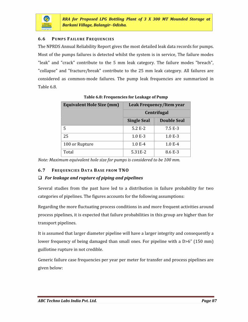
RRA for Proposed LPG Bottling Plant of 3 X 300 MT Mounded Storage atBarkani Village, Balangir- Odisha.
ABC Techno Labs India Pvt. Ltd. Page 87
6.6 PUMP S FAIL URE FREQ UENC IE SThe NPRDS Annual Reliability Report gives the most detailed leak data records for pumps.Most of the pumps failures is detected whilst the system is in service, The failure modes"leak" and "crack" contribute to the 5 mm leak category. The failure modes "breach","collapse" and "fracture/break" contribute to the 25 mm leak category. All failures areconsidered as common-mode failures. The pump leak frequencies are summarized inTable 6.8.Table 6.8: Frequencies for Leakage of Pump
Equivalent Hole Size (mm) Leak Frequency/Item year
Centrifugal
Single Seal Double Seal5 5.2 E-2 7.5 E-325 1.0 E-3 1.0 E-3100 or Rupture 1.0 E-4 1.0 E-4Total 5.31E-2 8.6 E-3Note: Maximum equivalent hole size for pumps is considered to be 100 mm.
6.7 FRE Q UENC IES DATA BASE FR OM TNO For leakage and rupture of piping and pipelinesSeveral studies from the past have led to a distribution in failure probability for twocategories of pipelines. The figures accounts for the following assumptions:Regarding the more fluctuating process conditions in and more frequent activities aroundprocess pipelines, it is expected that failure probabilities in this group are higher than fortransport pipelines.It is assumed that larger diameter pipeline will have a larger integrity and consequently alower frequency of being damaged than small ones. For pipeline with a D>6” (150 mm)guillotine rupture in not credible.Generic failure case frequencies per year per meter for transfer and process pipelines aregiven below:
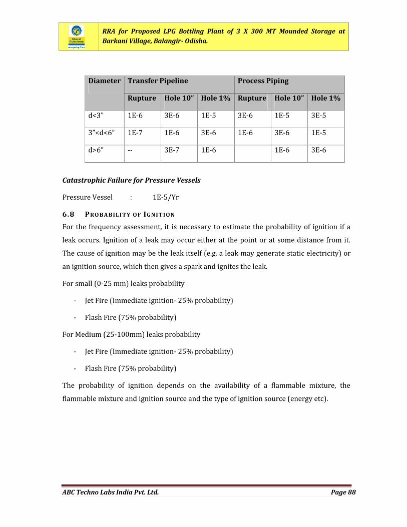
RRA for Proposed LPG Bottling Plant of 3 X 300 MT Mounded Storage atBarkani Village, Balangir- Odisha.
ABC Techno Labs India Pvt. Ltd. Page 88
Diameter Transfer Pipeline Process Piping
Rupture Hole 10” Hole 1% Rupture Hole 10” Hole 1%d<3” 1E-6 3E-6 1E-5 3E-6 1E-5 3E-53”<d<6” 1E-7 1E-6 3E-6 1E-6 3E-6 1E-5d>6” -- 3E-7 1E-6 1E-6 3E-6Catastrophic Failure for Pressure VesselsPressure Vessel : 1E-5/Yr6.8 PRO BA BILITY OF IGN I TIONFor the frequency assessment, it is necessary to estimate the probability of ignition if aleak occurs. Ignition of a leak may occur either at the point or at some distance from it.The cause of ignition may be the leak itself (e.g. a leak may generate static electricity) oran ignition source, which then gives a spark and ignites the leak.For small (0-25 mm) leaks probability- Jet Fire (Immediate ignition- 25% probability)- Flash Fire (75% probability)For Medium (25-100mm) leaks probability- Jet Fire (Immediate ignition- 25% probability)- Flash Fire (75% probability)The probability of ignition depends on the availability of a flammable mixture, theflammable mixture and ignition source and the type of ignition source (energy etc).
RRA for Proposed LPG Bottling Plant of 3 X 300 MT Mounded Storage atBarkani Village, Balangir- Odisha.
ABC Techno Labs India Pvt. Ltd. Page 89
CHAPTER 7
RISK ANALYSIS AND SUMMATION
RRA for Proposed LPG Bottling Plant of 3 X 300 MT Mounded Storage atBarkani Village, Balangir- Odisha.
ABC Techno Labs India Pvt. Ltd. Page 90
CHAPTER 7: RISK ANALYSIS AND SUMMATION
8.1 GENERALRisk is defined as the unwanted consequence of a particular activity in relation to thelikelihood that this may occur. Risk thus comprises of two variables: magnitude ofconsequences and the probability of occurrence. The risk analysis and summation aremost often presented in terms of individual and group or societal risk.Individual Risk is the probability of death occurring as a result of accidents at a plant,installation or a transport route expressed as a function of the distance from such anactivity. Such a risk actually exists only when a person is permanently at that spot (out ofdoors). The individual risk is well illustrated with the aid of risk - curves or Iso-riskcontours.Societal or group risk is the probability of a certain number of victims per year. Incalculating the group risk demographic data relating to the presence of humans isnecessary. The societal risk is represented as an F-N curve, which depicts the frequency ofoccurrence per year (F) of a certain number of fatalities, (N).The individual and societal risks from a proposed LPG bottling plant are the result of thecumulating of risks connected with all possible scenarios. From the standpoint of whatconstitutes acceptable risk levels from a complex, both the Individual as well as SocietalRisks should be within the acceptance criteria.8.2 SOFTWA RE MO DEL USED RI SK SUM MATIONThe DNV Software model SAFETI 6.53.1 (PHAST RISK 6.53.1) has been used for plottingthe iso-risk contour of individual risk and F-N curves of Societal Risk. The ‘PHAST RISK’program package is a very powerful tool to combine the probabilities and consequencesof all release scenarios considered into risk and then sum them.Data input to SAFETI 6.53.1 (PHAST RISK 6.53.1) comprises of results of effects-consequence and frequency analyses for the scenarios included for risk summation, alongwith population and meteorological data for the locality in question. The effects-consequence and frequency analyses for the selected releases have been summarised inChapter 4 and Chapter 5, respectively.
RRA for Proposed LPG Bottling Plant of 3 X 300 MT Mounded Storage atBarkani Village, Balangir- Odisha.
ABC Techno Labs India Pvt. Ltd. Page 91
8.3 RISK SUM MATIONThe results of risk summation have been reproduced as individual and societal risks.Individual and societal risks are defined as below:8.3.1 IN DIVI DUAL RI SKThe individual risk at a certain distance from LPG storage and handling facilities is theresult of the cumulation of risks connected with all possible scenarios. The calculation ofindividual risk at a geographical location near a LPG storage and handling facility assumesthat the contributions of all incident outcome cases are additive. Thus, the total individualrisk at each point is equal to the sum of the individual risks, at that point, of all incidentoutcome cases associated with the LPG bottling plant.IR x,y = i=1n IR x,y,iWhereIR x,y = the total individual risk of fatality at geographical location x,y (chances of fatalityper year)IR x,y,i = the individual risk of fatality at geographical location x, y from incident outcomecase i (chances of fatality per year)n = the total number of incident outcome cases considered in the analysis.The individual risk of fatality at particular geographical location is calculated by thefollowing equation: IRx,y,I = Pa.Ps.Pw.frWherePa = accident probability (per year)Ps = Weather stability probabilityPw = Wind direction probabilityfr = response fraction
RRA for Proposed LPG Bottling Plant of 3 X 300 MT Mounded Storage atBarkani Village, Balangir- Odisha.
ABC Techno Labs India Pvt. Ltd. Page 92
The calculation of individual risk requires the application of these equations at everygeographical location surrounding the facility.8.3.2 SOC IETAL RI SKSocietal risk is the probability of a certain number of victims per year. In calculating thegroup risk, demographic data relating to the presence of humans is necessary. From thestand point of what constitutes an acceptable risk level from a complex, both theIndividual as well as societal risk should be within the acceptance criteria.The need for the societal risk computation arises due to the fact that society viewsmultiple fatalities from the same accident far more seriously than single fatalities fromnumerous accidents. All of the information required for individual risk calculation is alsorequired for societal risk estimation. Additionally information on the populationsurrounding the facility and its distribution is also required.The number of people affected by each incident outcome case is given by
Ni = Px,y. Pf,iWhereNi = number of fatalities resulting from incident outcome case iPx,y = number of people at location x, yPf,i = the probability that incident outcome case i will result in a fatality atlocation x, y from the consequence and effects model.8.4 RISK AC C EPTANC E CRI TERIAThe risk analysis provides a measure of the risk resulting from Mounded LPG Storage andhandling facility. The methodology for calculating risk levels has been well defined andconsistent results can therefore be expected. However, the assessment of theacceptability or otherwise of that risk is left to the judgement and experience of thepeople undertaking and/or using the risk assessment study. The normal approachadopted is to relate the risk measures obtained to risk acceptance criteria.
RRA for Proposed LPG Bottling Plant of 3 X 300 MT Mounded Storage atBarkani Village, Balangir- Odisha.
ABC Techno Labs India Pvt. Ltd. Page 93
8.4.1 CRITE RIA ADOPTE D F OR IN DI VI DUAL RI SKAs per “Code of Practices for Emergency Response and Disaster Management PlanRegulation 2010” formulated by Petroleum and Natural Gas Regulatory Board, underPetroleum and Natural Gas Regulatory Board Act 2006, Individual Risk per Annum (IRPA)has been adopted as given below:- 10-5 per year for tolerable risk- 10-6 per year for acceptable risk.- Lower than 10-6 per year for negligible risk.Individual Risk from 10-3 to 10-5 per Annum is considered tolerable in As Low AsReasonably Practicable (ALARP Zone)8.4.2 CRITE RIA ADOPTE D F OR SOC IETAL RI SK CRI TERIAIn the assessment of the societal risk, demographic data on the offsite of the LPG storageand handling facilities have been used. Only the employees working in the concerned LPGbottling plant are not included in the 'society'. With regard to the risk of people employedin nearby industries with similar risk, it is debatable to consider them as population.Internationally consensus is lacking on this aspect. However, in the present studyemployees in the adjoining industries have been considered as 'society' in the assessmentof societal risk.
FN CurveSlope
IntolerableIntercept With N=1
NegligibleIntercept WithN=1
Limit onN
Existing andNew Plants -1 10-3 10-5 -8.5 IN DIVI DUAL RI SK DUE TO PROPO SE D LPG BOTTLING PLANT FAC IL ITIESIndividual risk (IR) contours for proposed LPG storage and bottling Facilities are withinthe site. Failure frequency data for various release scenarios used for computation ofIndividual risk have been described in detail in Chapter 6 of RRA report.From the figure, it is observed that IR contours of 1.0E-5/average year are within theboundary of the LPG Bottling plant. Other IR contours are out side the terminal boundary.
RRA for Proposed LPG Bottling Plant of 3 X 300 MT Mounded Storage atBarkani Village, Balangir- Odisha.
ABC Techno Labs India Pvt. Ltd. Page 94
Therefore, it is below the risk tolerance criterion of individual risk contours of 1.0E-5/average year as it remains within LPG bottling plant boundary and does not reach topopulated areas out side the boundary of the PlantThe Individual Risk Potential for loss of life (Potential Loss of Life- PLL) due to proposedLPG bottling plant is 4.96512E-006 per average year.8.6 SOC IETAL RI SKThe individual risk values for each location when combined with population at thatlocation gives the societal risk at the same location i.e. the probability of a certain numberof victims per year. The total Societal Risk can be obtained by adding the values for all thelocations. The Societal risk is represented as F-N Curve, frequency of number of fatalities(F) from all the accidents versus number of fatalities (N). FN curves (Figure 7.1 andFigure 7.2) show two straight lines (with negative slope) which indicate the Societal RiskAcceptance criteria adopted for this study. The region above the upper line (1E-3) inFigure 6.2 and Figure 6.3 is the region of unacceptable risk, while that below the lowerline ((1E-5)) is the region of acceptable risk. The region in between is the so-called ALARPZone where risk is acceptable subject to its being As Low As Reasonably Practicable (TheALARP principle). Major risk contributors have been identified using the Analysis Toolsfeature of PHAST RISK.For LPG storage and bottling facilities, F-N Curves have been drawn separately for dayand night time and for combined day and night time and are shown in Figure 7.1 andFigure 7.2, respectively. Failure frequency data for various release scenarios used forcomputation of Societal Risk have been described in detail in Chapter 6 of RRA report.From Figure 7.1 and Figure 7.2, it is observed that the F-N Curve of societal risk lies wellbelow the ALARP Zone in negligible zone at proposed LPG Bottling Plant. Due to proposedfacilities at the LPG bottling plant, computation shows that Societal Risk potential for lossof life is 6.95124E-007 per average year. From LPG bottling plant, it is observed thatmaximum 01 fatality results for cumulative frequency of 6.95124E-007 per average yearwhich is also below the ALARP zone, hence, societal risk is negligible as there will be notbe residential area.
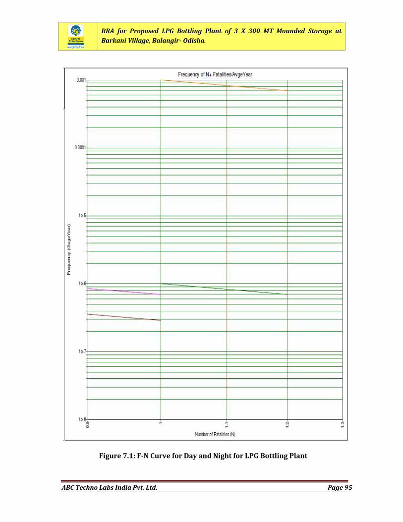
RRA for Proposed LPG Bottling Plant of 3 X 300 MT Mounded Storage atBarkani Village, Balangir- Odisha.
ABC Techno Labs India Pvt. Ltd. Page 95
Figure 7.1: F-N Curve for Day and Night for LPG Bottling Plant
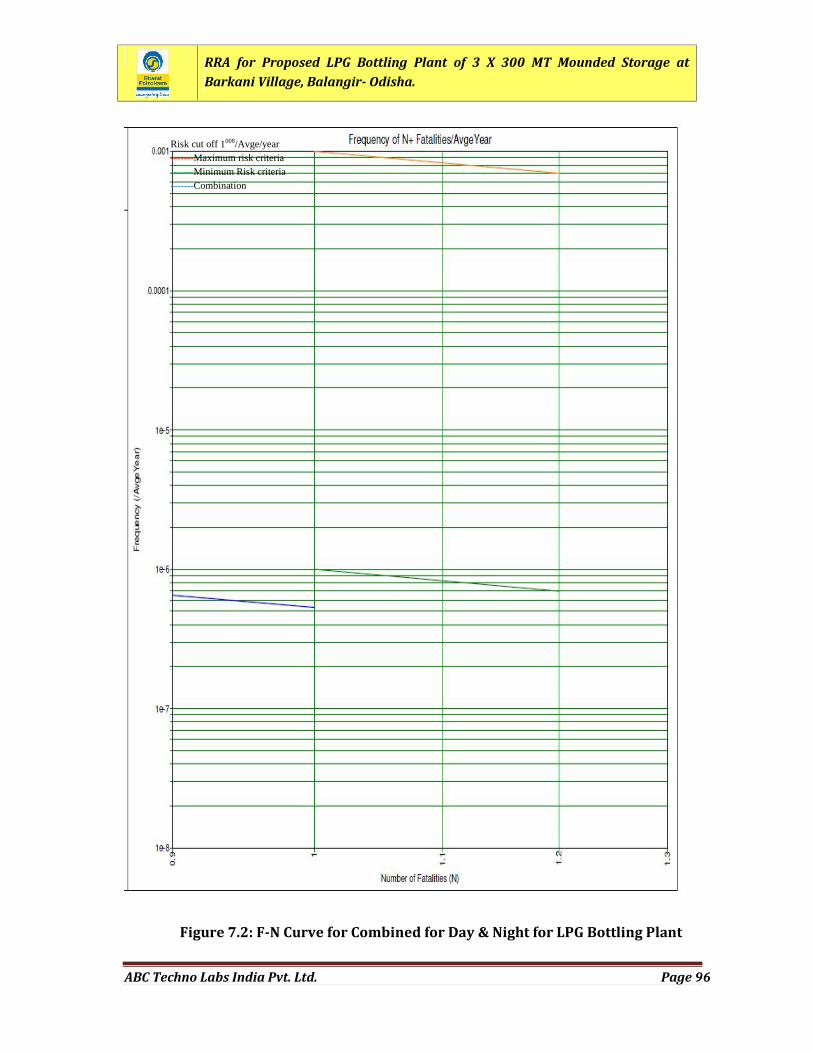
RRA for Proposed LPG Bottling Plant of 3 X 300 MT Mounded Storage atBarkani Village, Balangir- Odisha.
ABC Techno Labs India Pvt. Ltd. Page 96
Figure 7.2: F-N Curve for Combined for Day & Night for LPG Bottling Plant
Risk cut off 1008/Avge/year-------Maximum risk criteria-------Minimum Risk criteria-------Combination
RRA for Proposed LPG Bottling Plant of 3 X 300 MT Mounded Storage atBarkani Village, Balangir- Odisha.
ABC Techno Labs India Pvt. Ltd. Page 97
8.7 FIN DING S OF RI SK AN ALYSI SBased on Risk analysis and summation, following observations can be made:i. Individual risk from proposed LPG bottling plant at Balangir is negligible, as it isbelow the tolerance criterion of individual risk, as 4.96512E-006 per year riskcontour remains within BPCL LPG Bottling Plant boundary.ii. It is observed that for the LPG Bottling Plant, 1 fatality may result for a cumulativefrequency of 6.95124E-007 per average year which is well below the ALARP zoneand hence is negligible.iii. The Societal Risk Potential for loss of life (Potential Loss of Life- PLL) due toproposed LPG Bottling Plant is 6.95124E-007 per avg. year.
RRA for Proposed LPG Bottling Plant of 3 X 300 MT Mounded Storage atBarkani Village, Balangir- Odisha.
ABC Techno Labs India Pvt. Ltd. Page 98
CHAPTER 8
RISK REDUCTION MEASURES
RRA for Proposed LPG Bottling Plant of 3 X 300 MT Mounded Storage atBarkani Village, Balangir- Odisha.
ABC Techno Labs India Pvt. Ltd. Page 99
CHAPTER 8: RISK REDUCTION MEASURES
8.1 PREAM BLERisk Assessment study provides a quantitative technique for assessing the significance ofthe impact of any facility on its external environment, highlights key areas for greaterattention and provides a tool for comparing alternative options. Though, it can notsubstitute for close attention to the fundamentals of safety throughout the design processor for design reviews.For risk reduction, attempts should be made to either reduce inventories that could getreleased in the event of loss of containment or failure likelihood or both as far as feasible.Risk Assessment identifies the dominant risk contributors, which enables prioritisation ofplants/section that deserve special attention in terms of inspection and maintenance inparticular and over all safety management as a whole.8.2 RISK M ITIGAT ION ME ASURE S LPG BOTTLIN G PLANTThe proposed LPG botlling plant will be major accident hazard installation underManufacture, Storage, Import of Hazardous Chemicals. Rule, 1989 and subsequentamendments. During design, construction and operation of the proposed facilities,numbers of safety provisions and risk reduction measures will need to be implementedand followed meticulously in compliance with applicable acts, rules, regulations, codes,standards, guidelines and best industry practices. This also includes provisions of notonly state-of-the-art equipment, control and instrumentation to enhance safety but alsohigh level induction and refresher safety trainings from senior management tocontractual workers levels at the facilities.The major risk mitigation measures for the proposed LPG bottling plant facilities aredescribed below:8.2.1 LPG UNLOA DIN G FAC I LITIESTo reduce the risk of accidental LPG release during product transfer, excess flow checkvalves shall be provided in LPG loading/ unloading lines.
RRA for Proposed LPG Bottling Plant of 3 X 300 MT Mounded Storage atBarkani Village, Balangir- Odisha.
ABC Techno Labs India Pvt. Ltd. Page 100
8.2.2 CYLIN DE R FILLIN G FA C ILITIES
A. Filling Machines And Weighingi. The filling machines shall be provided with auto cut-off system so that the liquidand gas supply is cut off when the desired quantity of product has been filled in thecylinders. The filling pressure shall not be more than the design pressure of thecylinders i.e. 16.9 kg/sq.cm. gauge.ii. Filling machines in a carousel/stationary filling machines shall not have aweighment error of more than +1% of the net quantity of the LPG filled in thecylinder, with a capacity of 14.2/19/37.5 kg.iii. It is recommended that in-line check weigh scales with a minimum of 50 gms.graduation be installed so that all the cylinders can be check weighed after filling.B. Layout And Safetyi. The cylinder filling area shall be completely open type and covered from top withasbestos roof designed to ensure good natural ventilation, RCC roofing shall not beused. The filling area will not be on upper floors of building or in cellars.ii. As far as possible, the floor area shall not have any channels or pits. Where theseare necessary for conveyors or other equipment like weigh machine etc., suitablegas detection system shall be provided. Additionally they shall be ventilatedthrough ducts fitted with blowers to outside of the shed at safe location. The wholeof the LPG filling shed flooring shall be provided with bitumenistic mastic flooring.iii. Adequate lighting shall be provided in the cylinder filling area. Additionallyemergency lighting shall also be provided at critical places.iv. Water drains from the cylinder filling area where they enter an outside drainagesystem, shall be provided with vapour seals.v. Fixed water spray system shall be installed for fire fighting inside the cylinderfilling area as described in section 4.4. Besides this, access shall be made availablefor other fire fighting systems.
RRA for Proposed LPG Bottling Plant of 3 X 300 MT Mounded Storage atBarkani Village, Balangir- Odisha.
ABC Techno Labs India Pvt. Ltd. Page 101
C. Cylinder StorageMaximum cylinder storage of empty and filled cylinders combined shall be restricted to atotal of 3 days bottling capacity of the plant. Storage area requirement shall be based onthe stacking pattern of filled and empty cylinders described in section 7.2.8.2.3 SAFETY/ SEC URIT Y SY STEMThe features of safety/ security system for the different areas in the LPG bottling plantsshall be as follows:8.2.3.1 AUT OMATIC FI RE PRO TEC TION SY STEMAutomatic fire protection (Fixed) system based on heat detection through thermal fuses/quartz bulbs/ EP detectors shall be employed. Sensors shall be installed at all criticalplaces described below:A. LPG Storage AreaIn storage area these detectors shall be provided encircling each vessel, equi-spaced witha maximum spacing of 1 meter at an elevation of about 1.5 to 2.0 meter from bottom ofvessel. Also minimum 2 nos. detectors shall be provided at the top of the vessel andatleast one near the liquid line ROV to take care of failure of flanges. In case of anautomatic thermal fuse based fire protection system the instrument air supply pressureto thermal fuses shall be maintained through a pressure control valve and a restrictionorifice.The thermal fuses shall be designed to blow at 79 deg C temperature (max). Instrumentair will start leaking as a result of thermal fuse blowing. The capacity of the restrictionorifice is such that the discharge of air through even one thermal fuse will depressurisethe downstream side of the restriction orifice to below set point of the pressure switch.The actuation of pressure switch on any one of the vessels shall initiate the following : an audio visual alarm at the local/ main control panel and fire water station,indicating the vessel on fire. the Remove Operated Valve (ROV) on liquid inlet/ outlet line to the affected vesselwill close.
RRA for Proposed LPG Bottling Plant of 3 X 300 MT Mounded Storage atBarkani Village, Balangir- Odisha.
ABC Techno Labs India Pvt. Ltd. Page 102
the ROVs on vapour balance line and liquid return line of the affected vessel willclose. LPG pumps and compressors in LPG storage area will trip. the deluge valves on fire water supply lines to that vessel will open.Additionally push buttons for initiating all the above actions shall be provided on remoteoperating panel and also in field at safe location for enabling manual actuation of a trip byoperator. In the field, manual bypass valves of fire water deluge valves shall also beprovided. Arrangement to routinely test the security system shall also be provided.
B. Other AreasDetectors shall be placed at critical locations in LPG sheds (filling, cylinder storage,testing, evacuation, etc.) loading/ unloading gantries, LPG compressor house, pipingmanifold, repair sheds etc. Upon actuation there shall be alarm in central panel, LPGpumps and compressors would trip, ROVs (wherever provided) on LPG supply and returnlines would trip and the deluge valves on fire water sprinkler system will get actuated.The fire water deluge valves shall be kept outside the kerb wall at a safe distance in caseof sphere/ bullet, and located 15 M away from limits of other sheds or shadows ofspheres. A fire wall shall be provided for the protection of the deluge valve and forpersonal protection of the operator.8.2.3.2 GAS DETEC TION SY ST EMSuitable gas detectors shall be placed at identified critical locations in the LPG storage,compressor house, pump house, filling shed, cylinder storage area, evacuation/ testingarea, LPG loading/ unloading area.This shall include the area described in 4.2.4 B and shall also include places where water,draining/ sampling are done on a routine basis. Audio visual alarms showing the locationof gas leakage shall be provided on the control panel. First level alarm can be set at 20%LEL and second level alarm at 60% LEL.8.2.3.3 GAS EXT RAC TION SY STEMA gas extraction system having suction points at critical places where gas concentration ishigh like carousel, evacuation, valve change shed etc. shall be provided.
RRA for Proposed LPG Bottling Plant of 3 X 300 MT Mounded Storage atBarkani Village, Balangir- Odisha.
ABC Techno Labs India Pvt. Ltd. Page 103
8.2.4 OTHE R EQ UIPM ENT/ SYSTEM
8.2.4.1 BOTTLING PUMP SThere shall be a minimum of two pumps, including one standby. Pumps shall be providedwith suction and discharge pressure gauges, a high point vent to safe height or flare, and asuction strainer. Mechanical seal shall be provided (double mechanical seal with sealfailure alarms is preferred). A pressure switch actuating a low pressure alarm in controlroom shall be provided, taken from pump discharge. Pumps shall be designed to build adischarge pressure such that the pressure at the carousel filling machine is at least 5.0kg/sq.cm.g. above the vapour pressure at the operating temperature.Typical sketch of a bottling pump installation is enclosed as Annexure-1.
8.2.4.2 LPG COMP RE SSO RGear driven compressor shall preferably be used. However belt driven compressors canalso be used provided the belts used are antistatic type & fire resistant. There shall be aminimum of two compressors including one as a standby.The operating parameters shall be decided on a case to case basis. However, typicaloperating conditions may be as follows:Suction pressure 10.0 kg/sq.cm.g abs (max.) during unloading2-11.8 kg/sq.cm.g abs during vapour recovery.Discharge pressure 13.0 kg/sqcm.g. abs during unloading.11.5 kg/sqcm.g. abs during vapour recovery.Compressor shall be provided with the following features as a minimum: Pressure gauges in suction and discharge. Temperature gauge in discharge Discharge safety valve and a vent valve, their outlets leading to flare/ safe heightoutside the shed. Suction and discharge block valves (lock open type) Suction strainer Check valve in discharge
RRA for Proposed LPG Bottling Plant of 3 X 300 MT Mounded Storage atBarkani Village, Balangir- Odisha.
ABC Techno Labs India Pvt. Ltd. Page 104
A discharge to suction recycle valve for achieving capacity turndown duringstartup.8.2.5 EVAC UATIO N FAC ILITY FOR SIC K/ LEAKY CY LINDE R SThe cylinder evacuation facility shall consist of: Cylinder emptying vessels (2 nos) Compressor (1 no.) Four way valves Cylinder rack, header to be provided with pressure gauge and a strainer withisolation valves. The LPG line exit cylinder evacuation area to be provided with a non-return valvebefore joining the main LPG return header. Independent earthing connections shall be provided.Each of cylinder emptying vessels mentioned above shall be equipped with the following: Pressure gauges Level gauges and high level alarm switches Pressure relief valves and vent valves discharging to safe height. Other trims like drain valve, utility connection.
8.2.6 PUR GING OF NEW CYL INDE R S/ TANKE R Sa) The new LPG cylinders containing air shall be evacuated with a vacuum pump. Thevacuum pump shall be water/ oil cooled type. The evacuation facility shall consist of: Purging manifold Vacuum receiver fitted with vacuum gauge, vent and drain. LPG vapour header Purging adapters Portable oxygen analyzer Nitrogen cylinder manifold
RRA for Proposed LPG Bottling Plant of 3 X 300 MT Mounded Storage atBarkani Village, Balangir- Odisha.
ABC Techno Labs India Pvt. Ltd. Page 105
Vacuum pump with suction strainer Pressure regulator, relief valves etc.b) Purging of tankers/ vessels shall be done using either Nitrogen or by filling water anddisplacing with LPG vapours.There should be two independent lines (heads) one for evacuation of air and other forintroduction of LPG.
8.2.7 ELEC TRIC AL AREA CLASSIFIC ATIONAll electrical fittings/ equipments to be of Flame-proof type in vulnerable areas. Forelectrical area classification IS-5571, IS-5572 (Part-1) and OISD Standard -113 shall bereferred.8.2.8 MOUN DE D BULLET SThe mounded storage of LPG has proved to be safer as compared to above ground storagevessels since it provides intrinsically passive and safe environment and eliminates thepossibility of Boiling Liquid Expanding Vapour Explosion (BLEVE). The cover of themound protects the vessel from fire engulfment, radiation from a fire in close proximityand acts of sabotage or vandalism. The area of land required to locate a mounded systemis minimal compared to conventional storage.The following measures are suggested during design, erection and operation of moundedstorage bullets for LPG.i. Provisions of “OISD Standards 150: Design and Safety Requirements For LiquefiedPetroleum Gas Mounded Storage Facility” shall be included in design andoperation.ii. Each mound bullet shall have accessibility to fire tender from at least two sides.iii. Minimum separation distance between mounded LPG storage and any other (otherthan LPG pump/compressor house) facility associated with LPG plant shall be 15meters. This distance to be measured from the edge of the mound at finishedground level and also from the first valve on the vessel i.e. ROV.
RRA for Proposed LPG Bottling Plant of 3 X 300 MT Mounded Storage atBarkani Village, Balangir- Odisha.
ABC Techno Labs India Pvt. Ltd. Page 106
iv. The minimum inter-distance between the edge of the vessel in a mound shall notbe less than 2 meters.v. Proper provision shall be made for countering the consequences of the settlementof the vessel under mound. The surrounding of the bottom connection should befilled with such material that can absorb such settlement.vi. Provision shall be made to monitor the settlements of the mound by providingpermanent reference point. A minimum of three reference points shall be installedto be able to also identify possible vessel bending (One each near the vessel endsand one in the middle.)vii. The fire safe Remote Operated Shutdown Valve (ROV) on liquid drain line from thevessel shall be either from bottom of the vessel or from the top of the vessel as perthe design considerations.viii. In case of liquid drain line from the bottom of the vessel, the minimum distance of3 meters from the vessel to ROV shall be maintained. The nozzle pipe shall have aslope of 1.5 Deg.ix. There shall not be any other flanges, or any other tapping up-to the ROV except incase of liquid drain line from top of the vessels.x. Each vessel shall have at-least two pressure relief valves. The full flow capacity ofPressure Relief Valves (PRV) on mounded vessels may be reduced to not less than30% of the capacity required for an equivalent size of above ground vessel. Forsafety reasons, the discharge of Pressure Relief Valves shall be connected to flaresystem. In this case Pressure Relief Valves (PRVs) shall have lock open (or car sealopen) type isolation valves on both sides of Pressure Relief Valve.xi. The Pressure Relief valves shall be tested and calibrated every year by acompetent person and records shall be maintained.xii. Cathodic protection system shall be provided, maintained and tested routinely.xiii. Any change in the system will be marked on P&ID. The system of “Management ofChanges” may be developed as per “Guidelines on Management of Change” (OISDGDN 178).
RRA for Proposed LPG Bottling Plant of 3 X 300 MT Mounded Storage atBarkani Village, Balangir- Odisha.
ABC Techno Labs India Pvt. Ltd. Page 107
xiv. Any repairs or modifications should be undertaken after statutory approval fromapplicable authority.xv. Each storage vessel shall have minimum two different types of level indicators andone independent high level switch. High level alarms shall be set at not more than85% level of the volumetric capacity of the vessel.xvi. Audiovisual indication shall be at local panel and control room.xvii. Automatic fire detection and /or protection (Fixed) system based on heatdetection through thermal fuses/ quartz bulbs shall be employed. Sensors shall beinstalled at all critical places including as described below: Minimum 1 detector shall be provided on each exposed portion of thevessel. However if the nozzles are covered in a dome, each group shall have2 numbers of detectors. Atleast one near the each liquid line ROV to take care of failure of flanges.xviii. Suitable gas detectors shall be placed at critical locations in the LPG storage areasuch as, near the ROV, in inspection tunnel, near water draining/ sampling points,etc.xix. Audio- visual alarms showing the location of gas leakage shall be provided on thecontrol panel in the control room. First level alarm can be set at 20% LEL andsecond level alarm at 60 % LEL of LPG.xx. All mounded storage vessels, LPG Pump Houses, truck tanker gantries shall befully covered by medium velocity water spray system.xxi. LPG storage area, automatic detection of heat for automatic actuation of mediumvelocity sprinkler system having remote/ local operated deluge valve with spraydensity of 10 lpm/m2 of surface area shall be provided.xxii. Hydrant and monitor coverage shall also be provided on all four sides of themounds for adequate coverage of unprotected portions exposed to thermalradiation including for top of the mound and for piping, in the immediate vicinityof the mound. In view of accessibility of unprotected portions of the vessels, for
RRA for Proposed LPG Bottling Plant of 3 X 300 MT Mounded Storage atBarkani Village, Balangir- Odisha.
ABC Techno Labs India Pvt. Ltd. Page 108
effectiveness, installation of remote operated monitors at appropriate height shallbe considered.xxiii. Hydrant /monitors shall be located at a safe place around the mound. In any casefire hydrant and/or monitors shall not be installed within 15 meters from thefacilities/equipment to be protected.8.2.9 PROC E DURE FO R UNLOADI NG TANK TR UC K SThe following procedures should be followed, while, unloading LPG bullets trucks: Checks essential for plant safety shall be carried out for each Tank Truck before itsentry to the licensed area I. Tank pressure, temperature and weight of filled tank truck shall be recorded. Tank shall be placed in drive out position with entire tank truck consisting ofbullet and engine covered by sprinklers. After placement, engine as well as master control switch shall be switched off andminimum two wooden chokes shall be placed under wheels.The following shall be connected:a. Chassis and bullets both are to be earthed independently for which baremetal cleats to be provided.b. Liquid and vapour hoses to tank trucks after examining the integrity ofgaskets and using proper studs. Bolts and nuts are not be used.c. Earthing lines to tank bare metal or earthing point to tank.d. Liquid and vapour hoses to tank trucks. The tank truck valves shall be crack opened and ensured there are no leaks. After the above, unloading should be done preferably with LPG compressor bydifferential pressure method. Pressure and level in the tank truck shall be monitored at regular intervals so thatit does not exceed safe limits. After decanting all liquid LPG, close the valve ofliquid line of the bay. Thereafter, LPG vapour should be recovered such that
RRA for Proposed LPG Bottling Plant of 3 X 300 MT Mounded Storage atBarkani Village, Balangir- Odisha.
ABC Techno Labs India Pvt. Ltd. Page 109
vapour pressure in the tank truck is brought down to 1.5 kg/cm2 minimum butnot below atmospheric pressure. On completion of unloading, following operations shall be done in sequence :a. Isolate rigid liquid and vapour lines of bay by closing the valves and stopLPG compressor.b. Close the valves of liquid/ vapour lines of the tank truck. Depressurise thehose through high vent - close vent valve.c. Remove hose connections, electrical bonding wires.d. Cap the vapour/ liquid outlet lines of tank trucks.e. Remove chokes placed under wheels. Record the weight of empty tank truck along with rotogauge, pressure gauge andtemperature gauge readings.
8.2.10 HAN DLING & ST O RAG E OF LPG CYLINDER S IN C YLINDER FILLING AND
C YLINDE R STO RAGE SH E DHandling and storage of LPG cylinders shall be governed by Gas Cylinders Rules, 1981.The following safe practices shall be observed:a) Handling of LPG Cylinders - LPG cylinders shall not be dropped, rolled on sides andshall not be subjected to any violent contact with any other cylinder or object cylindershall be moved by rolling on its foot ring or on conveyors or hand trolleys.b) Defective filled cylinders - Any cylinder having body leak, bung leak, bulge, fireravaged or spurious shall be evacuated immediately.Any cylinder with valve leak shall be immediately capped and thereafter evacuatedimmediately. Cylinders requiring repairs other than valve leak/ Bung leak shall bedegassed for repairs. All above cylinders shall be clearly identified, with markers, to theirnature of defects and shall be kept capped during storage.c) LPG cylinder storage - All cylinders shall be stacked vertically (with valve in uprightposition) in not more than 2 stack high. Cylinders of different capacity and type shallbe stacked separately. All cylinders shall be capped during storage.
RRA for Proposed LPG Bottling Plant of 3 X 300 MT Mounded Storage atBarkani Village, Balangir- Odisha.
ABC Techno Labs India Pvt. Ltd. Page 110
The cylinders shall be stacked in small lots of 4 rows and 25 cylinders length. A minimumaccess path of 1 m must be maintained on both sides of 4 rows and 2 m after every 5 suchlots. After each length of 25 cylinders, there must be a passage of 2 m. The cylinderstorage space shall be properly marked/ painted on the flooring.Empty and filled cylinders shall be demarcated clearly. Minimum distance of 15 m fromcylinder loading area and minimum distance of 10 m from filling point shall be observedfor all filled cylinders stack.8.2.11 MAINTENANC E SC HE DULE SThe proper preventive maintenance schedule should be prepared to facilitate themaintenance service to be rendered in a planned manner covering the necessary work tobe done, mentioning the periodicity i.e. daily, weekly, monthly, half yearly and yearlyschedules.8.2.12 ELEC TRIC AL HAZA R DSSome Important measures to minimise electrical hazards are as given below: The classification of area for electrical installations at LPG storage and handlingfacilities shall be as per OISD Standards 113. Inspection of electrical equipment shall be carried out as per OISD Standards 137. All electrical equipments shall be provided with proper earthing. Earth pits shall be periodically tested and maintained in good condition. Emergency lighting shall be available at all critical locations including fire pumproom, control room, etc. All electrical equipments shall be free from carbon dust, oil deposits, and grease. All electrical cable will be tagged for easy identification and cable routing shall beplanned away from heat sources, gas, water, oil, drain piping and air conditioningducts. All lights in LPG storage area, pump house, loading gantry, etc will be flame proof.
RRA for Proposed LPG Bottling Plant of 3 X 300 MT Mounded Storage atBarkani Village, Balangir- Odisha.
ABC Techno Labs India Pvt. Ltd. Page 111
Provisions shall be made for approved insulated tools, rubber mats, shock proofgloves and boots, tester, fuse tongs, discharge rod, hand lamp, insulated ladder. Flame and shock detectors and central fire announcement system for fire safetyshall be provided in MCC control panel room. Temperature sensitive alarm and protective relays to make alert and disconnectequipment before overheating shall be provided. Danger from excess current due to overload or short circuit should be preventedby providing fuses, circuit breakers, thermal protection, etc. Only carbon dioxide and dry chemical fire extinguishers shall be used for electricalfires.
8.2.13 FIRE F IGHTI NG FAC ILI TIESFire protection system shall be designed in accordance with the requirements of OISD,NFPA standards, design requirements and safe engineering practices. Fire fightingfacilities should have full capability for early detection and suppression of fire. The firefighting system will primarily consist of: Hydrant system Foam protection system Deluge sprinkler system Portable fire extinguisher Fire detection and alarm systemAfter commissioning of proposed LPG bottling plant, fire fighting facilities should beaugmented as per relevant OISD/NFPA/ TAC Standards. Fire water requirement and firewater storage shall be evaluated for two fires for 4 hours at any point of time in the LPGbottling plant.
8.2.14 CONT ROL ROO M
Control room shall be located at a sufficient distance from operating areas All control room should be blast proof and shock proof.
RRA for Proposed LPG Bottling Plant of 3 X 300 MT Mounded Storage atBarkani Village, Balangir- Odisha.
ABC Techno Labs India Pvt. Ltd. Page 112
Critical switches and alarm should be always kept in line. Minimum number of doors shall be provided in the control room while at least twodoors should be provided for safe exit during emergency. Smoke detection system shall be provided for control room.
8.2.15 PERSONAL PROTEC TIO N EQ UIP MENTNecessary personal protection equipments such as Hand gloves, Safety shoes, Helmets,Safety belts, Safety goggles etc. shall be used (Ref. OISD STD-155).8.2.16 WORK PERMIT SY STE MNo maintenance/ inspection work shall be carried out without following the OISDStandard OISD-105 on "Work Permit System" and Section 4 of OISD-137 for electricalmaintenance purpose.8.2.17 SAFETY AUDIT AN D IN SPEC TIONChecklist based routine inspection and safety audits should be carried out in line withOISD -144 for mounded bullets, pumps, piping and loading gantries, etc. Any gap or noncompliance should be implemented on priority in time bound manner.8.2.18 IN DUC TIO N AN D REF R ESHER SAFETY TRAINI NG SThe provision shall be made for structured induction and refresher safety trainings forLPG handling system from senior management to contractual workers levels at thefacilities.8.2.19 EME R GENC Y RE SPO N SE PLANAnticipating and planning for various contingencies is crucial for ensuring the success ofany emergency response actions in an actual Emergency Situation. On-site Emergencyresponse plan shall be prepared for LPG bottling plant, to take the action in an unlikelyevent of emergency due to accidental release of LPG. Emergency Response Plan should beupdated based on findings of mock drills.8.2.20 BULLET TR UC K CHEC K SFor bullet trucks, checks required to be carried out before allowing entry in the LPGbottling plant:
RRA for Proposed LPG Bottling Plant of 3 X 300 MT Mounded Storage atBarkani Village, Balangir- Odisha.
ABC Techno Labs India Pvt. Ltd. Page 113
It has suitable spark arrestor of make and design approved by CCE, Nagpurproperly fixed to exhaust. It carries 2 nos. 10 kg. DCP extinguishers in easily accessible and removableposition with Truck No. date of checking and charging painted on it. It has quick closing manifold valve with lever indicating close and open status. There is no visible dent on the bullet.
Electrical
All junction boxes are properly sealed Any loose electrical wiring/ terminal Electrical wiring is insulated and provided with suitable over current protection. Truck is self starting Readily accessible master switch for switching off the engine is provided inside thecabin. Dipole wiring.
Tank Fittings
Leakage from any fittings or joints.8.2.21 CHEC K S RE Q UIRE D T O BE CA RRI E D OUT BEFO RE ISSUIN G LOA DIN G
MEMO (DURIN G THE CO UR SE OF UNLOA DIN G OPERTI ON S )
Bullet Truck
Height barrier provided as per specifications Fuel tank is protected by means of stout guard and fuel tank cap is locked. Paint of bullet is not peeling off.
General
First aid kit is available.
RRA for Proposed LPG Bottling Plant of 3 X 300 MT Mounded Storage atBarkani Village, Balangir- Odisha.
ABC Techno Labs India Pvt. Ltd. Page 114
Checks Required To Be Carried Out On Random Basis - Minimum One Day, Once In AMonth:Tank Truck
Internals of fire extinguishers in good condition Carries TREM CARD, instructions booklet detailing instructions on handlingemergencies en route. Carries route map Carries TREM card Has valid CCE license and authenticated copy of drawing Carries RTO permits RLW-ULW> Licensed capacity HAZCHEM sign, name of contractor with address and telephone No. displayedprominently. Bullet has no sign of extern corrosion.
Tank Fittings
Excess flow check valves are functioning. Liquid / vapour lines are adequately anchored and are well protected by means ofstout steel guard. Liquid/ vapour pipe lines are in single piece from excess flow check valve todischarge valves - Safety fittings viz., safety valve, roto-gauge, pressure gauge andtemperature gauge are adequately protected. Operative fittings like roto gauge, pressure gauge and temperature gauge areoperational.
8.2.22 MOC K DRILL EXE RC ISESMock drill should be conducted once in six months. Exercises or drills have two basicfunctions, namely training and testing. While exercises do provide an effective means oftraining in response procedures, their primary purpose is to test the adequacy of the
RRA for Proposed LPG Bottling Plant of 3 X 300 MT Mounded Storage atBarkani Village, Balangir- Odisha.
ABC Techno Labs India Pvt. Ltd. Page 115
emergency management system and to ensure that all response elements are fullycapable of managing an likely emergency situations.Mock drills are best means of accomplishing the following goals and objectives: To reveal weaknesses in the plans and procedures before emergencies occur. To identify deficiencies in resources (both in manpower and equipment). To improve the level of co-ordination among various response personnel,departments and agencies. To clarify each individual’s role and areas of responsibility.
8.3 SAFETY MANAGEME NT SY STEM (SMS)The failure probabilities largely depend upon how effectively safety is being managed.This in turn necessitates, formal documented Safety Management System (SMS) asessential and effective. The features of a Safety Management System are described below.Analysis of industrial accidents and disasters has shown clearly that these are not simplya consequence of direct technical failure or operator tasks, which were carried outincorrectly. The underlying causes may be deeply routed in management aspects of theorganization. In some cases, the incidents could have been prevented with a formal SafetyManagement System (SMS). In other situations, a safety management system was in place,but did not prevent the occurrence of the incident. This suggests the need for a widerapplication of “best practice” safety management system in industry. Moreover, it raisesthe question of the quality of such systems.Safety Management System should be a function of reporting at the highest managementlevel.8.3.1 ELEM ENT S OF SAFETY MANAGEMENTSMS management comprises of a number of elements. For the sake of completeness, thecontents and elements of the Safety Management System are given below:i. Management leadership, commitment and accountabilityii. Risk Analysis, Assessment and Managementiii. Facilities design and construction
RRA for Proposed LPG Bottling Plant of 3 X 300 MT Mounded Storage atBarkani Village, Balangir- Odisha.
ABC Techno Labs India Pvt. Ltd. Page 116
iv. Process and facilities information and documentationv. Personnel safety and healthvi. Personnel trainingvii. Operation and maintenance proceduresviii. Work permitsix. Inspection and Maintenancex. Reliability and quality control of critical systems and devicesxi. Regulatory compliancexii. Management of changexiii. Third party audit and inspectionxiv. Incident reporting, analysis and follow-upxv. Emergency preparednessxvi. Community awarenessxvii. Operations integrity assessment and improvementBPCL should implement Safety Management System at the proposed LPG bottling plant.Effective monitoring and safety audit procedures may also be developed to ensure properimplementation and follow-up of safety management system at the facility.
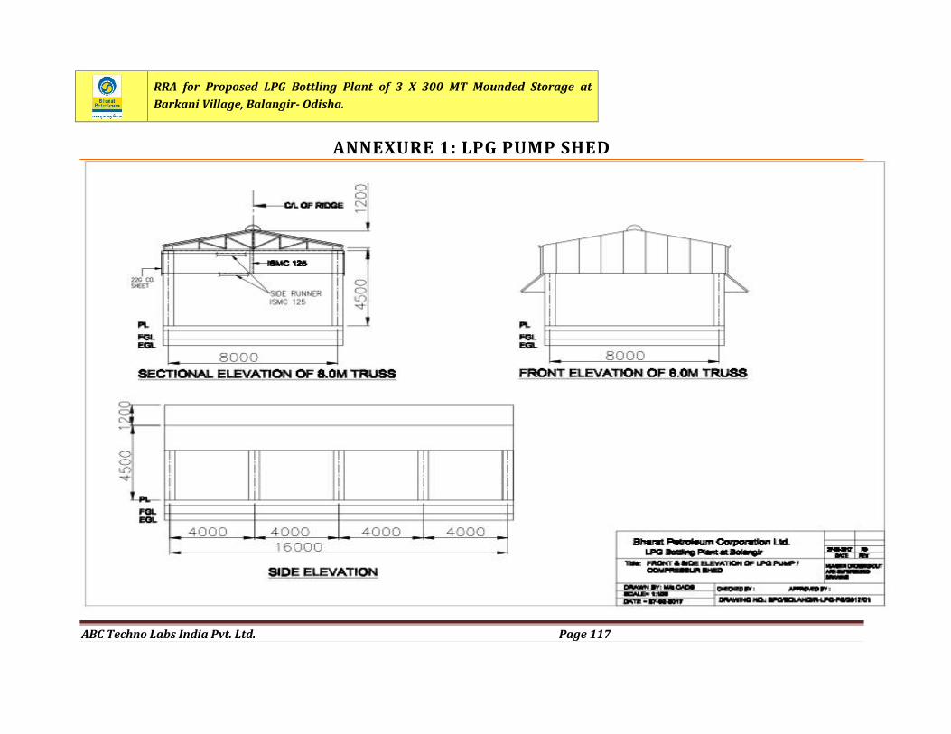
RRA for Proposed LPG Bottling Plant of 3 X 300 MT Mounded Storage atBarkani Village, Balangir- Odisha.
ABC Techno Labs India Pvt. Ltd. Page 117
ANNEXURE 1: LPG PUMP SHED
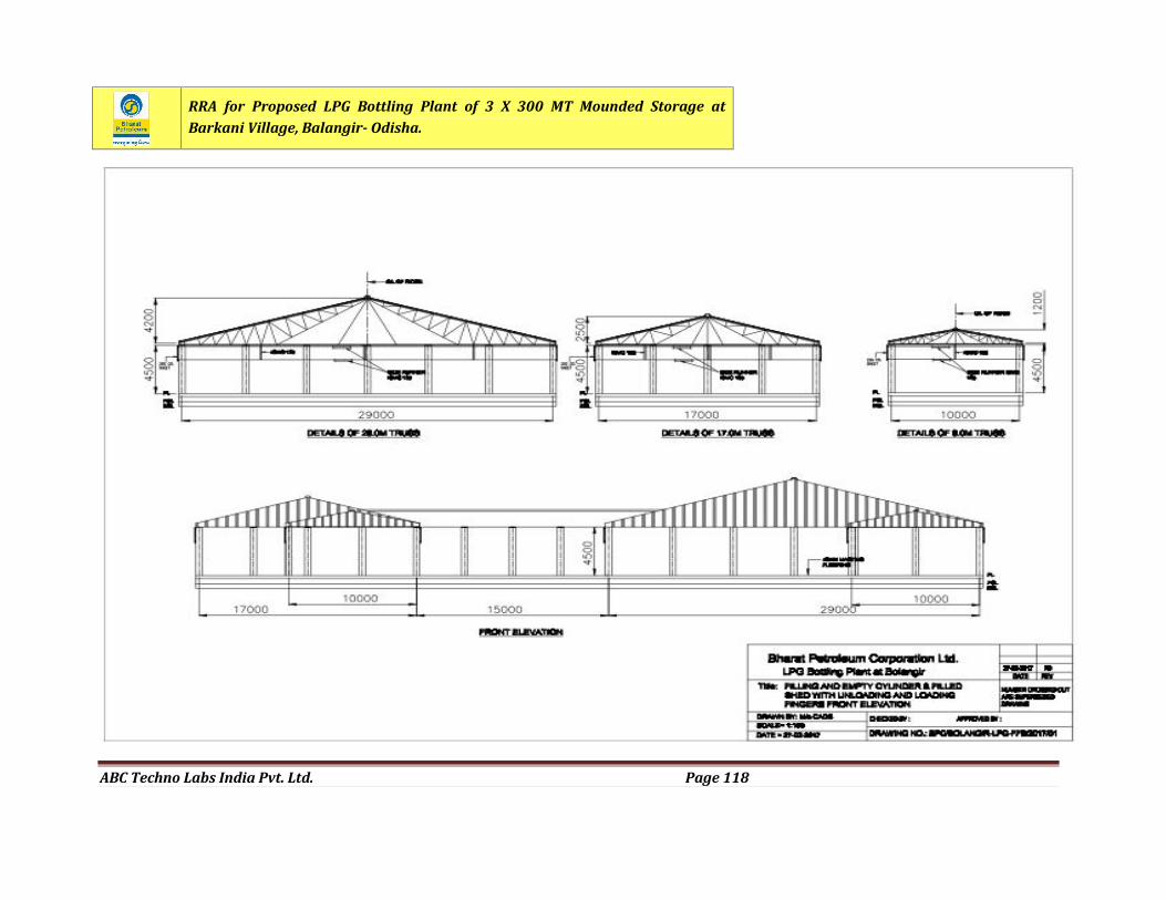
RRA for Proposed LPG Bottling Plant of 3 X 300 MT Mounded Storage atBarkani Village, Balangir- Odisha.
ABC Techno Labs India Pvt. Ltd. Page 118
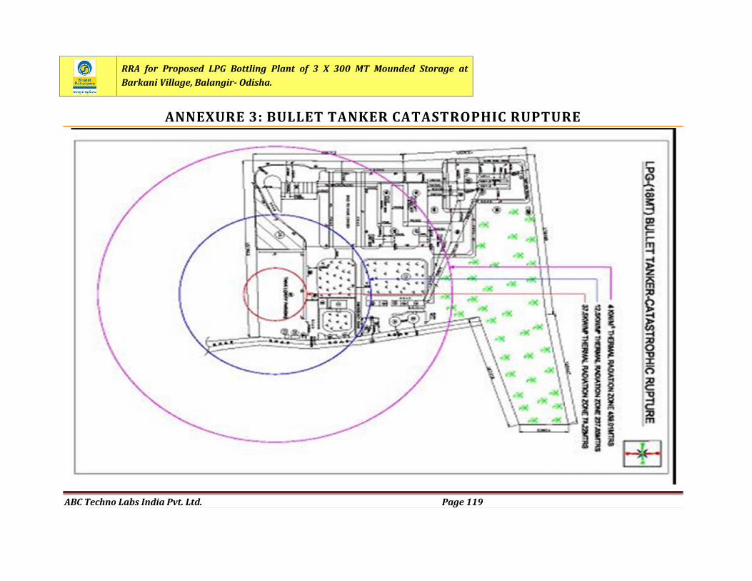
RRA for Proposed LPG Bottling Plant of 3 X 300 MT Mounded Storage atBarkani Village, Balangir- Odisha.
ABC Techno Labs India Pvt. Ltd. Page 119
ANNEXURE 3: BULLET TANKER CATASTROPHIC RUPTURE
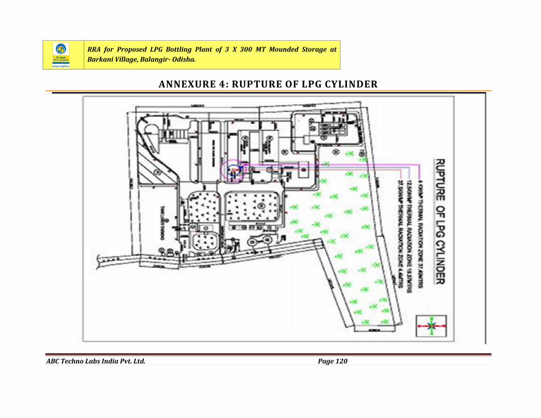
RRA for Proposed LPG Bottling Plant of 3 X 300 MT Mounded Storage atBarkani Village, Balangir- Odisha.
ABC Techno Labs India Pvt. Ltd. Page 120
ANNEXURE 4: RUPTURE OF LPG CYLINDER
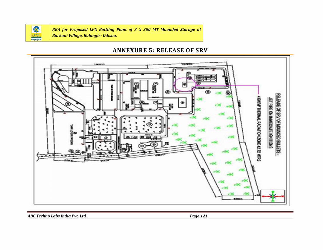
RRA for Proposed LPG Bottling Plant of 3 X 300 MT Mounded Storage atBarkani Village, Balangir- Odisha.
ABC Techno Labs India Pvt. Ltd. Page 121
ANNEXURE 5: RELEASE OF SRV
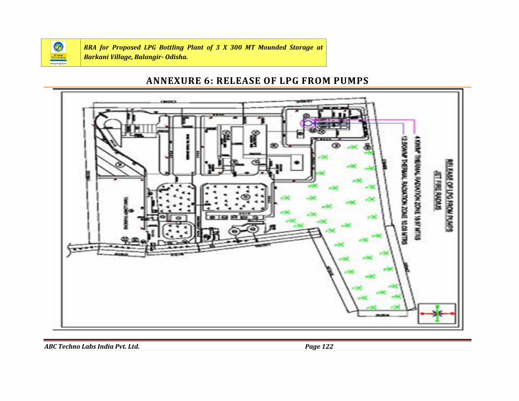
RRA for Proposed LPG Bottling Plant of 3 X 300 MT Mounded Storage atBarkani Village, Balangir- Odisha.
ABC Techno Labs India Pvt. Ltd. Page 122
ANNEXURE 6: RELEASE OF LPG FROM PUMPS
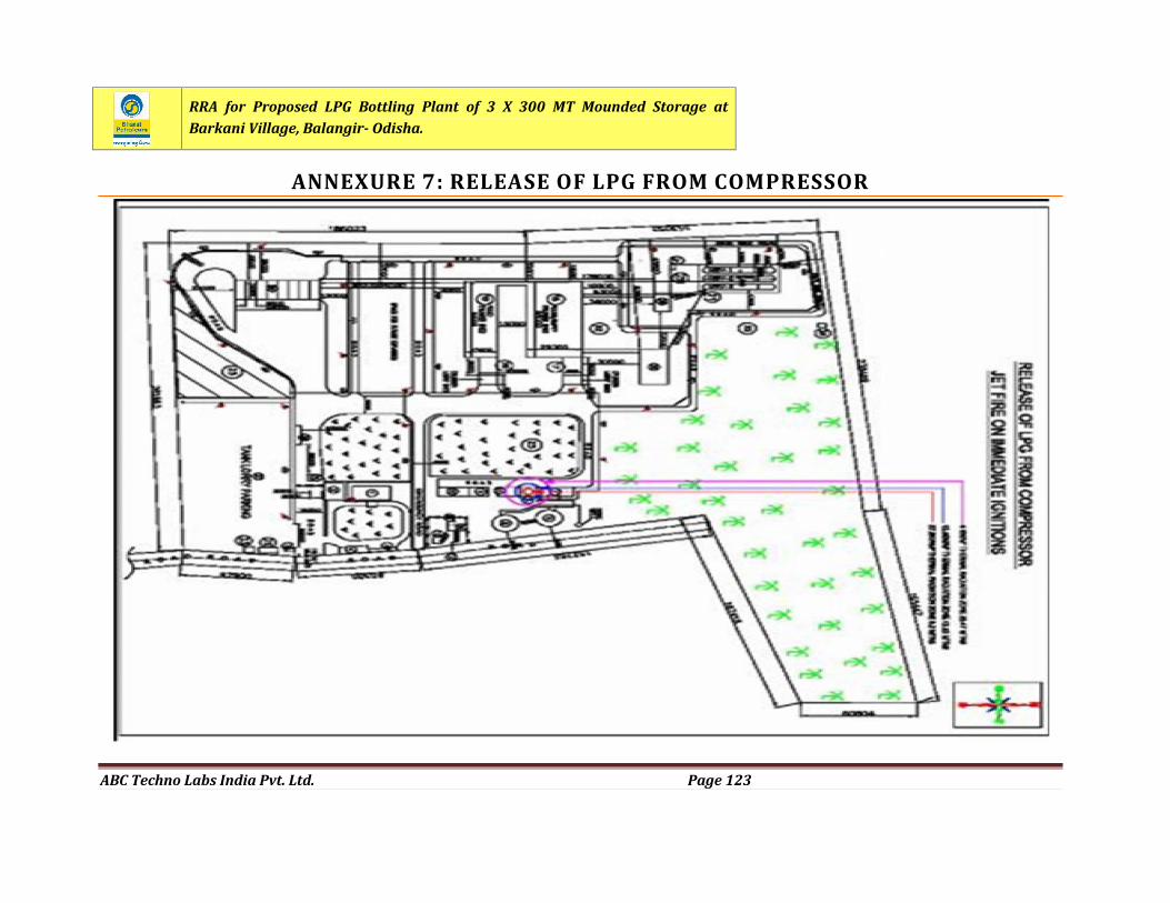
RRA for Proposed LPG Bottling Plant of 3 X 300 MT Mounded Storage atBarkani Village, Balangir- Odisha.
ABC Techno Labs India Pvt. Ltd. Page 123
ANNEXURE 7: RELEASE OF LPG FROM COMPRESSOR