Embed Size (px)
Citation preview
Back to basics…… Back to basics…… for for Foundation design Foundation design of of Monopile Support StructuresMonopile Support Structures
ByBy
Victor KrolisVictor Krolis
05/12/2007 European Offshore Wind energy conference 2007
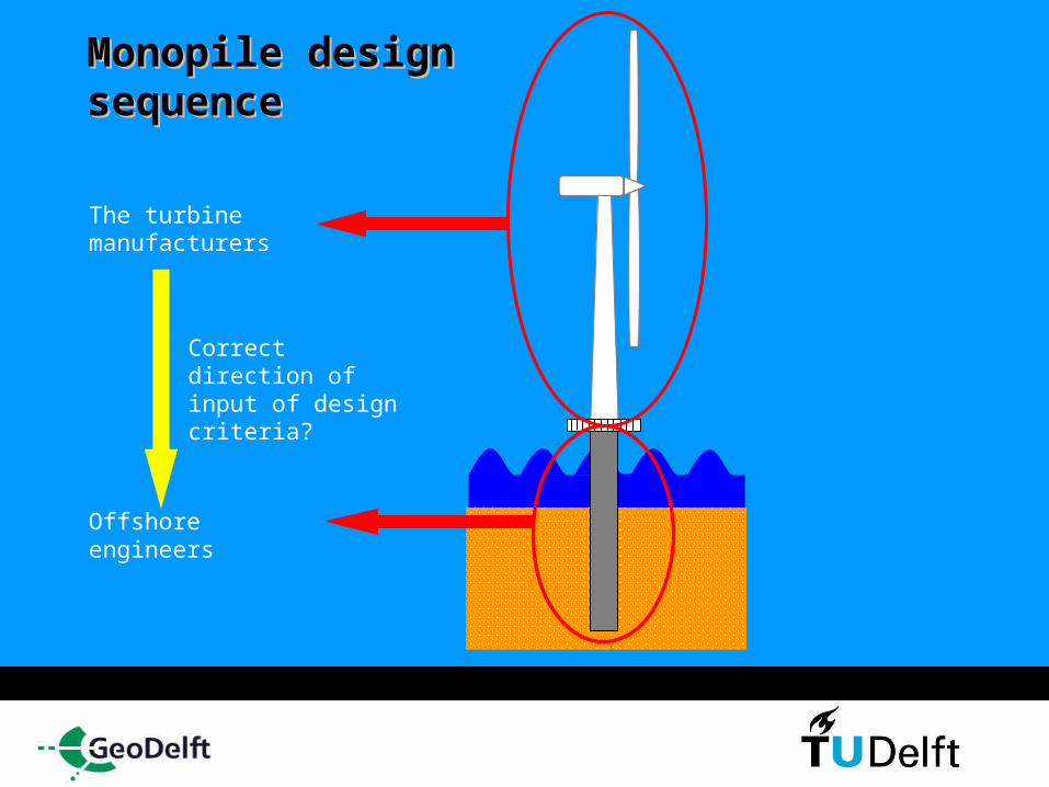
Monopile design Monopile design sequencesequence
The foundation takes about 30% of the total costs for one offshore wind turbine
The turbine manufacturers indirectly “shape” the design criteria for the foundation
Monopile design Monopile design sequencesequence
Offshore engineers
The turbine manufacturers
Correct direction of input of design criteria?
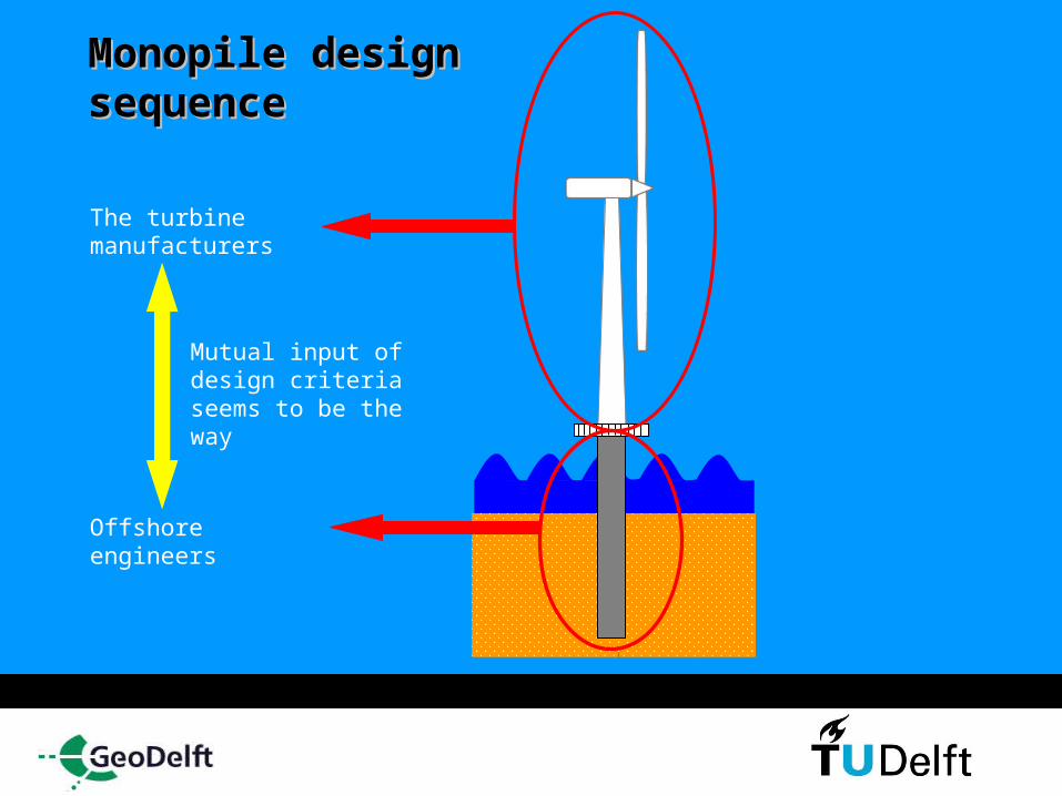
Monopile design Monopile design sequencesequence
Offshore engineers
The turbine manufacturers
Mutual input of design criteria seems to be the way

Why mutual input of design criteria?Why mutual input of design criteria?
Future:5 MW and larger turbines

Why mutual input of design criteria?Why mutual input of design criteria?
Future:5 MW and larger turbines
Heavier turbines

Why mutual input of design criteria?
Future:5 MW and larger turbines
Heavier turbines
Moving into deeper waters

Why mutual input of design criteria?
Future:5 MW and larger turbines
Heavier turbines
Moving into deeper waters
Larger Monopiles (> 5 m.) are needed since this is still an attractive type of
support structure economic wise
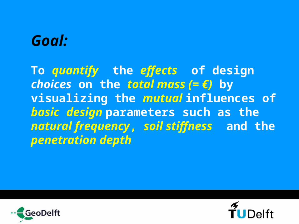
Goal:
To quantify the effects of design choices on the total mass (= €) by visualizing the mutual influences of basic design parameters such as the natural frequency, soil stiffness and the penetration depth
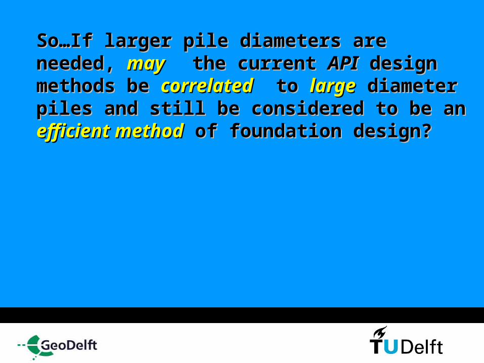
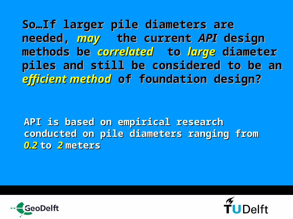
So…If larger pile diameters are needed, So…If larger pile diameters are needed, maymay the current the current APIAPI design methods design methods be be correlatedcorrelated to to largelarge diameter piles diameter piles and still be considered to be an and still be considered to be an efficient efficient methodmethod of foundation design?of foundation design?
So…If larger pile diameters are needed, So…If larger pile diameters are needed, maymay the current the current APIAPI design methods design methods be be correlatedcorrelated to to largelarge diameter piles diameter piles and still be considered to be an and still be considered to be an efficient efficient methodmethod of foundation design?of foundation design?
API is based on empirical research API is based on empirical research conducted on pile diameters ranging from conducted on pile diameters ranging from 0.2 0.2 to to 2 2 metersmeters
How due How due high numbershigh numbers of of cycliccyclic loading loading effecteffect these these largelarge diameter diameter piles?piles?

Shouldn’t we go Shouldn’t we go back toback to basics and basics and evaluate the evaluate the basic foundationbasic foundation design parametersdesign parameters for these for these largelarge diameter piles?diameter piles?

Answer:Answer:
YES!!YES!!
Why?Why?
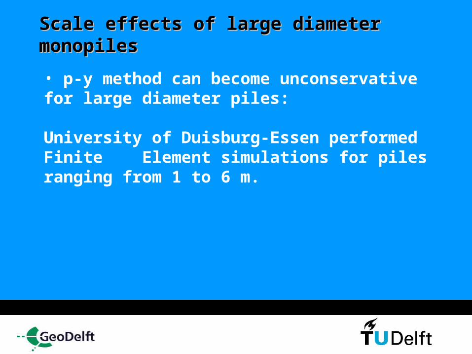
Scale effects of large diameter Scale effects of large diameter monopilesmonopiles • p-y method can become unconservative for large diameter piles:
University of Duisburg-Essen performed Finite Element simulations for piles ranging from 1 to 6 m.

Scale effects of large diameter monopiles
Deflection lines of 1m pile according to p-y method & SW method compared to the FE results [University of Duisburg-Essen, K. Lesny])
SWM
P-Y method
FE
SWM
P-Y method
FE
33 %
20 %
SWM
P-Y method
FE
SWM
P-Y method
FE
Pile deflection y [m]D
ep
th z
[m
]
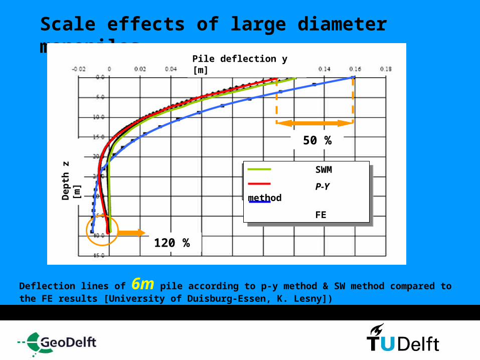
Scale effects of large diameter monopiles
Deflection lines of 6m pile according to p-y method & SW method compared to the FE results [University of Duisburg-Essen, K. Lesny])
50 %
120 %
SWM
P-Y method
FE
SWM
P-Y method
FE
Pile deflection y [m]D
ep
th z
[m
]
Effects of high numbers of cyclic loading Cyclic soil degradation: decrease of soil stiffness and strength

Effects of high numbers of cyclic loading
How can this be quantified for large diameter piles?
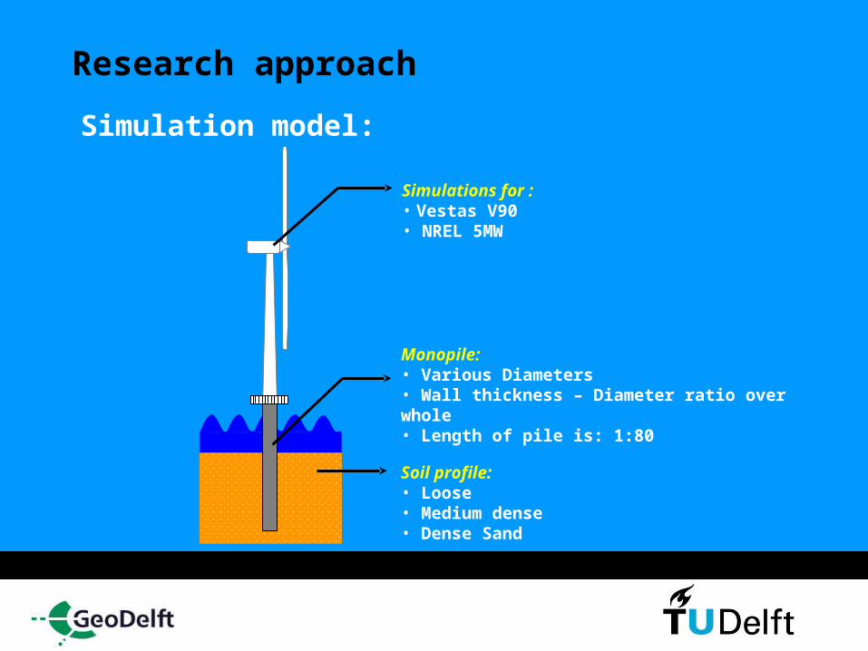
Research approach Simulation model:
Monopile:• Various Diameters• Wall thickness – Diameter ratio over whole • Length of pile is: 1:80
Simulations for : • Vestas V90 • NREL 5MW
Soil profile:• Loose• Medium dense • Dense Sand
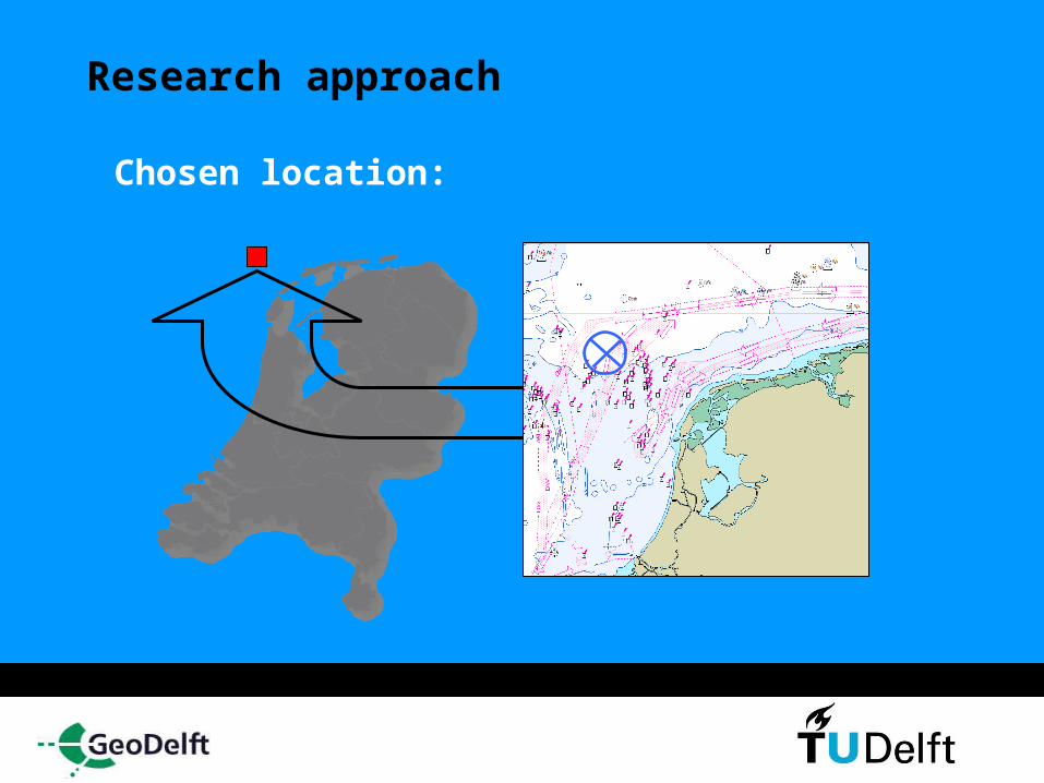
Research approach
Chosen location:
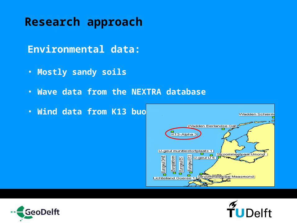
Research approach
Environmental data:
• Mostly sandy soils
• Wave data from the NEXTRA database
• Wind data from K13 buoy
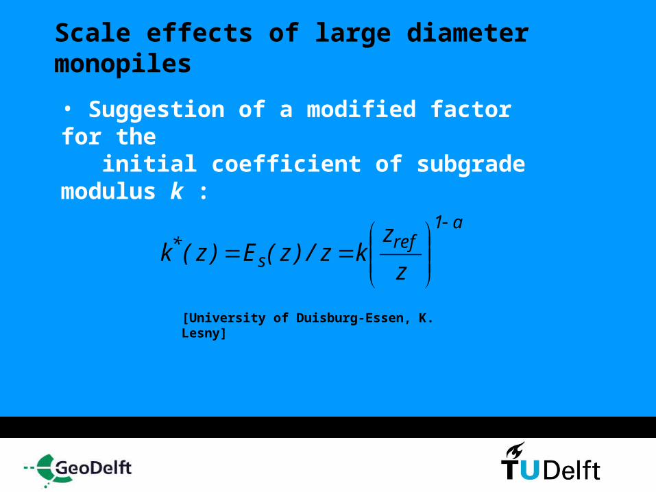
Scale effects of large diameter monopiles • Suggestion of a modified factor for the initial coefficient of subgrade modulus k :
a1ref
s*
z
zkz/)z(E)z(k
[University of Duisburg-Essen, K. Lesny]
Effects of high numbers of cyclic loading • Cyclic soil degradation: decrease of soil stiffness and strength
• Structural ‘shakedown’: stabilizing of permanent deflections after N number of cycles. If not…the pile will fail
Effects of high numbers of cyclic loading • Cyclic soil degradation: decrease of soil stiffness and strength
• Structural ‘shakedown’: stabilizing of permanent deflections after N number of cycles. If not…the pile will fail
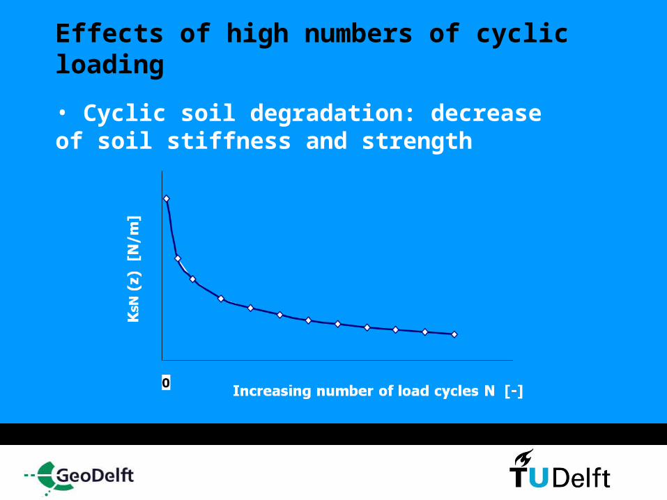
Effects of high numbers of cyclic loading • Cyclic soil degradation: decrease of soil stiffness and strength
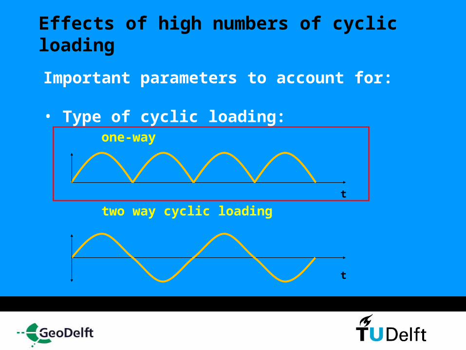
Effects of high numbers of cyclic loading Important parameters to account for:
• Type of cyclic loading: one-way
two way cyclic loading t
t
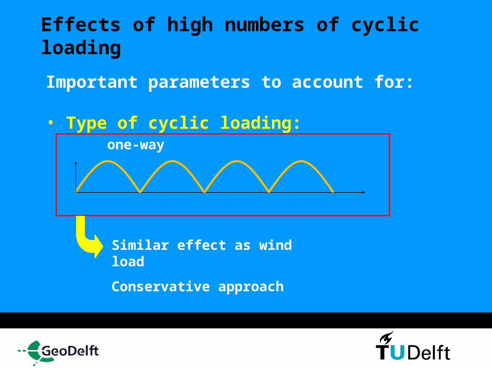
Effects of high numbers of cyclic loading Important parameters to account for:
• Type of cyclic loading: one-way
Similar effect as wind load
Conservative approach
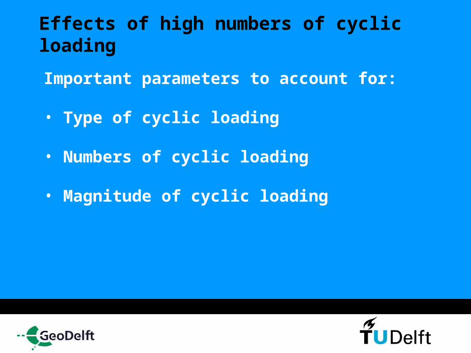
Effects of high numbers of cyclic loading Important parameters to account for:
• Type of cyclic loading
• Numbers of cyclic loading
• Magnitude of cyclic loading
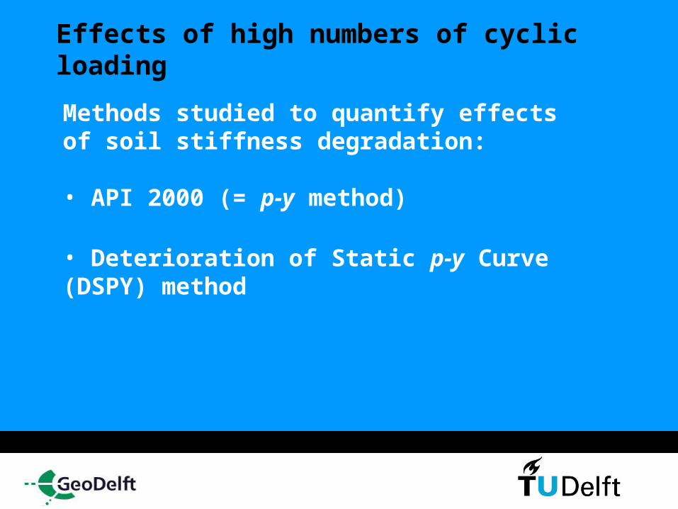
Effects of high numbers of cyclic loading Methods studied to quantify effects of soil stiffness degradation:
• API 2000 (= p-y method)
• Deterioration of Static p-y Curve (DSPY) method
Effects of high numbers of cyclic loading Methods studied to quantify effects of soil stiffness degradation:
• API 2000 (= p-y method)
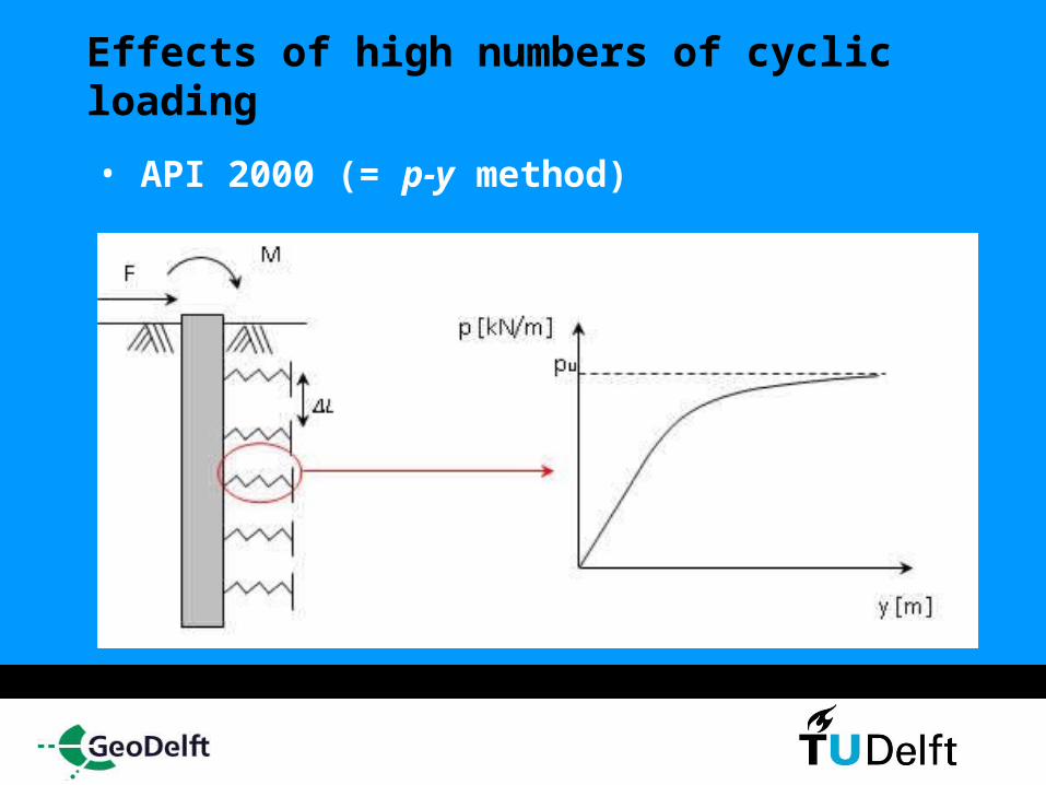
Effects of high numbers of cyclic loading • API 2000 (= p-y method)
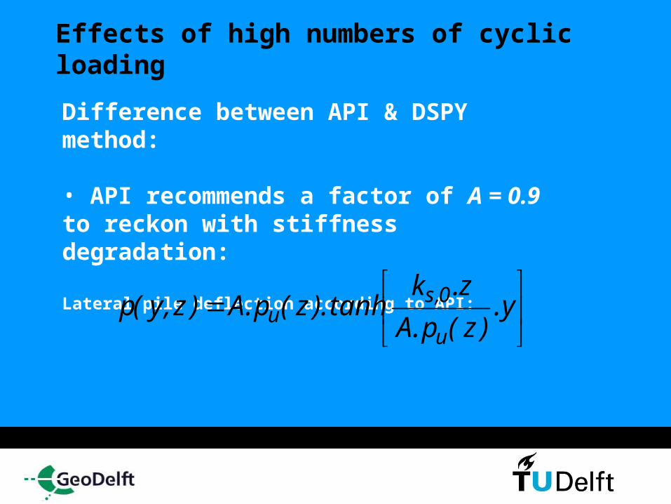
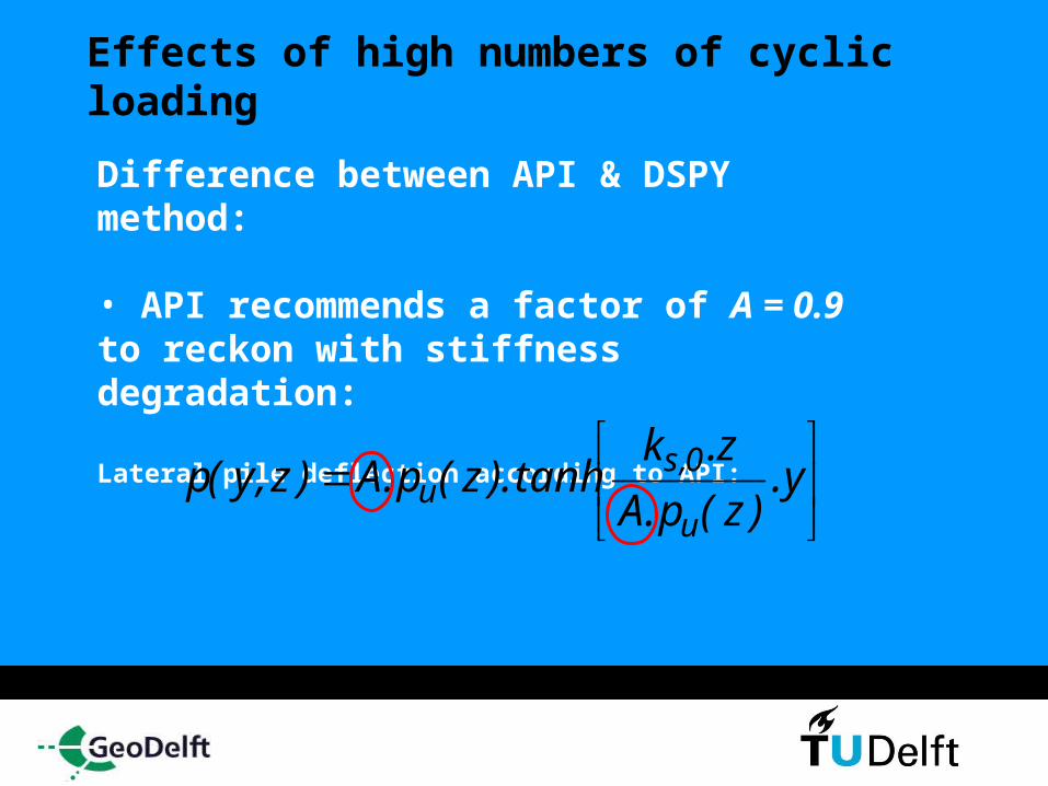
Effects of high numbers of cyclic loading Difference between API & DSPY method:
• API recommends a factor of A = 0.9 to reckon with stiffness degradation:
Effects of high numbers of cyclic loading Difference between API & DSPY method:
• API recommends a factor of A = 0.9 to reckon with stiffness degradation:
Lateral pile deflection according to API:
y.
)z(p.A
z.ktanh).z(p.A)z,y(p
u
0,su
Effects of high numbers of cyclic loading Difference between API & DSPY method:
• API recommends a factor of A = 0.9 to reckon with stiffness degradation:
Lateral pile deflection according to API:
y.
)z(p.A
z.ktanh).z(p.A)z,y(p
u
0,su

Effects of high numbers of cyclic loading Difference between API & DSPY method:
Lateral pile deflection according to API:
y.
)z(p.A
z.ktanh).z(p.A)z,y(p
u
0,su
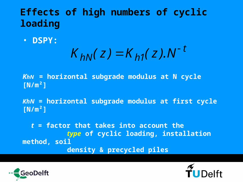
Effects of high numbers of cyclic loading • DSPY:
KhN = horizontal subgrade modulus at N cycle [N/m²] KhN = horizontal subgrade modulus at first cycle [N/m²]
t = factor that takes into account the type of cyclic loading, installation method, soil density & precycled piles
t1hhN N).z(K)z(K
Effects of high numbers of cyclic loading Simulation approach:
1. Model with environmental data available
2. Simulate for static load case determines static API p-y curves and static lateral
deflections
3. Determine cyclic p-y curves with DSPY method
4. Simulate cyclic load case determines cyclic API p-y curves
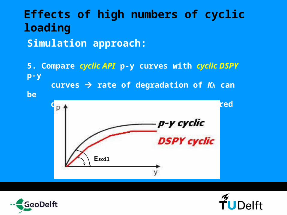
Effects of high numbers of cyclic loading Simulation approach:
5. Compare cyclic API p-y curves with cyclic DSPY p-y curves rate of degradation of Kh can be determined for both cases and compared
Esoil
Effects of high numbers of cyclic loading Simulation approach:
6. Simulate relative pile-soil stiffness ratio as a function of number of cycles
Numerical model for parametric studies Basic design parameters considered are:
• Natural frequency
• Soil stiffness (= subgrade modulus)
• Penetration depth
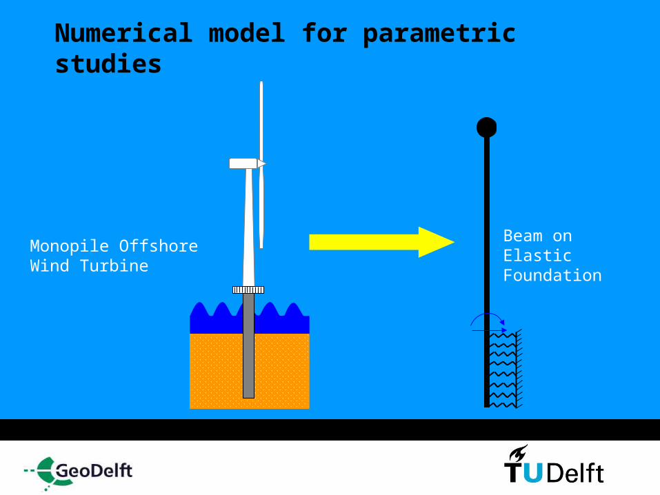
Numerical model for parametric studies
Monopile Offshore Wind Turbine
Beam on Elastic Foundation
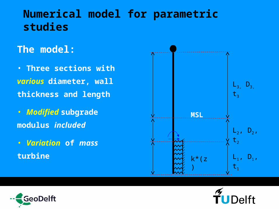
Numerical model for parametric studies
The model:
• Three sections with
various diameter,
wall thickness and
length
• Modified subgrade
modulus included
• Variation of mass
turbine
L3, D3, t3
L2, D2, t2
L1, D1, t1k*(z)
MSL
Analytical model for parametric studies Approach:
Perform parametric studies for existing offshore wind turbines such as the Vestas V90 and future turbines NREL 5MW

Analytical model for parametric studies Make 3D diagrams in which the effect of the diameter on the natural frequency, soil stiffness and penetration depth is visualized
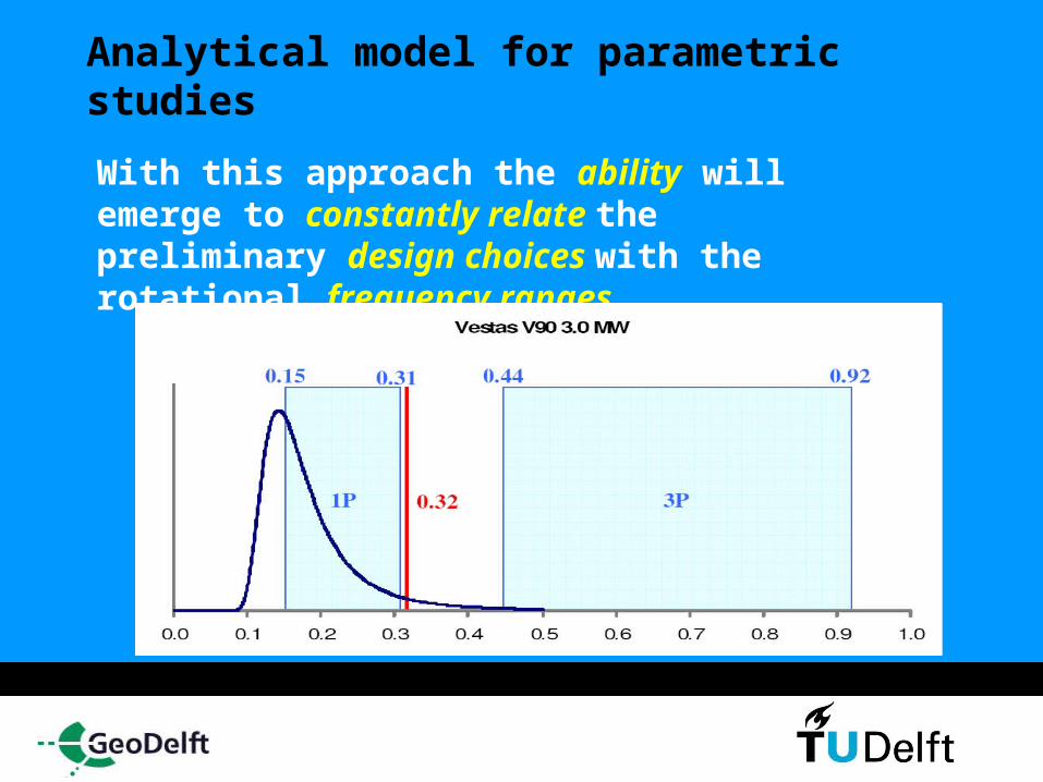
Analytical model for parametric studies With this approach the ability will emerge to constantly relate the preliminary design choices with the rotational frequency ranges

Acknowledgement
This research is sponsored by Geodelft
From January 2007 it will be incorporated in Deltares
www.Deltares.nl

THANK YOU!!


![Delft University of Technology PISA: Recent developments ... · reduce the dimensions and costs for laterally loaded offshore wind turbine monopile foundations [1–3]. The work proposes](https://img.pdfslide.us/doc/110x75/5ea8f916a06c370de614cbdf/delft-university-of-technology-pisa-recent-developments-reduce-the-dimensions.jpg)