Embed Size (px)
Citation preview
Aalborg Universitet
Active Vibration Control of a Monopile Offshore Structure
Nielsen, Søren R. K.; Kirkegaard, Poul Henning; Thesbjerg, L.
Published in:Structural Control and Health Monitoring
DOI (link to publication from Publisher):10.1002/stc.4300060203
Publication date:1999
Document VersionPublisher's PDF, also known as Version of record
Link to publication from Aalborg University
Citation for published version (APA):Nielsen, S. R. K., Kirkegaard, P. H., & Thesbjerg, L. (1999). Active Vibration Control of a Monopile OffshoreStructure. DOI: 10.1002/stc.4300060203
General rightsCopyright and moral rights for the publications made accessible in the public portal are retained by the authors and/or other copyright ownersand it is a condition of accessing publications that users recognise and abide by the legal requirements associated with these rights.
? Users may download and print one copy of any publication from the public portal for the purpose of private study or research. ? You may not further distribute the material or use it for any profit-making activity or commercial gain ? You may freely distribute the URL identifying the publication in the public portal ?
Take down policyIf you believe that this document breaches copyright please contact us at [email protected] providing details, and we will remove access tothe work immediately and investigate your claim.
Downloaded from vbn.aau.dk on: juli 13, 2018
JOURNAL OF S T R U ~ A L CONTROL. VOL. 6 N. 2 DECEMBER 1999 223
Active Vibration Control of a Monopile Offshore Structure
S.R.K. Nielsen, P.H. Kirkegaard Dept. of Building Technology and Structural Eng. Aalborg University DK-9000 Aalborg - Denmark
and L. Thesbjerg Rambdl A /S fiodesgade 125.4 DK-6700 Esbjerg - Denmark
September 9, 1999
Abstract. In the Danish part of the North Sea monopile platforms with a cylindrical shaft have been used at the exploitation of marginal fields. In the paper a new principle for active vibration control of such structures is suggested. The principle is based on a control of the boundary layer flow around the cylinder of the platform, so the drag force in the generalized Morison equation is increased whenever it is acting in the opposite direction of the cylinder motion, whereas an unchanged drag force is applied, whenever it is acting co-directionally to the cylinder motion. The inertial force of the wave load is not subjected to control. The increased drag force is obtained by forcing the boundary layers to separate by blowing air into the boundary layer from the inside through small holes in the cylinder surface placed at a relatively large distance from the water surface. The control is specified by the sign of the fluid velocity relative to the platform, and only this quantity need to be measured, which is easily performed by a flow meter fixed to the platform. The efficiency of the described closed loop control system has been verified by model tests in a wave flume in both regular and irregular wave conditions, where reductions in the vibration level of up to 50% have been registered. Key words: Active vibration control, Offshore structures, Monopile, Boundary layer flow, Wave mechanics
1 Introduction
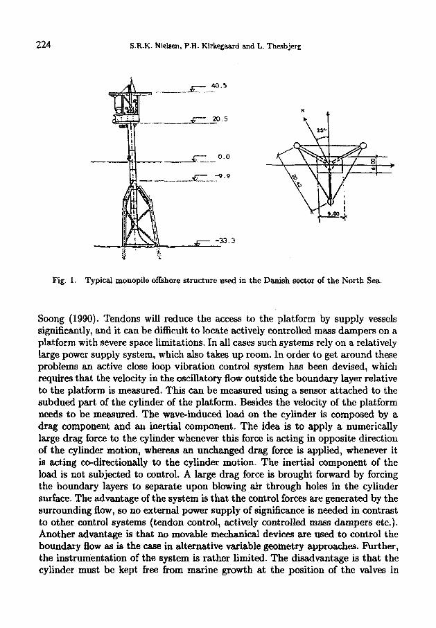
In the Danish sector of the North Sea it has been found that marginal fields can be exploited using monopile offshore platforms as the one shown in fig. 1 with significant advantages with respect to the costs involved in hbrication and installation, which can tip the economic balance favourably. The monopile platform has been developed for approximately 35 m water depth and is assumed to be remotely operated. This means that the dynamic responses, which in any case is relatively small, can be ignored with respect to collapse and comfort criteria. Only fatigue life is affected by the dynamic or quasi-static response of the platform. Recently, there has been a wish to use the monopile concept on 75 m water depth. At such water depths significant dynamic problems can be anticipated. Further, the platform is now assumed to be manned, so comfort criteria also have to be considered. Therefore, it can be necessary to use an active vibration control system to reduce the vibration levels. Various active vibration systems have been proposed in the literature such as tendon control and actively controlled mass dampers,
224 S.R.K. Nielaen, P.H. Kirkegaard and L. Thesbjerg
Fig. 1. Typical monopile offshore structure used in the Danish sector of the North Sea.
Soong (1990). Tendons will reduce the access to the platform by supply vessels significantly, and it can be difficult to locate actively controlled mass dampers on a platform with severe space limitations. In all cases such systems rely on a relatively large power supply system, which also takes up room. In order to get around these problems an active close loop vibration control system has been devised, which requires that the velocity in the oscillatory flow outside the boundary layer relative to the platform is measured. This can be measured using a sensor attached to the subdued part of the cylinder of the platform. Besides the velocity of the platform needs to be measured. The wave-induced load on the cylinder is composed by a drag component and an inertial component. The idea is to apply a numerically large drag force to the cylinder whenever this force is acting in opposite direction of the cylinder motion, whereas an unchanged drag force is applied, whenever it is acting co-directionally to the cylinder motion. The inertial component of the load is not subjected to control. A large drag force is brought forward by forcing the boundary layers to separate upon blowing air through holes in the cylinder surface. The advantage of the system is that the control forces are generated by the surrounding flow, so no external power supply of significance is needed in contrast to other control systems (tendon control, actively controlled mass dampers etc.). Another advantage is that no movable mechanical devices are used to control the boundary flow as is the case in alternative variable geometry approaches. Further, the instrumentation of the system is rather limited. The disadvantage is that the cylinder must be kept free from marine growth at the position of the valves in
Active Vibration Control 225
order to insure free passage of the air blown out, which may be a problem since the optimal position of holes for blowing out air is shown to be at a relatively large water depth. The details of the control concept are further explained in the following section.
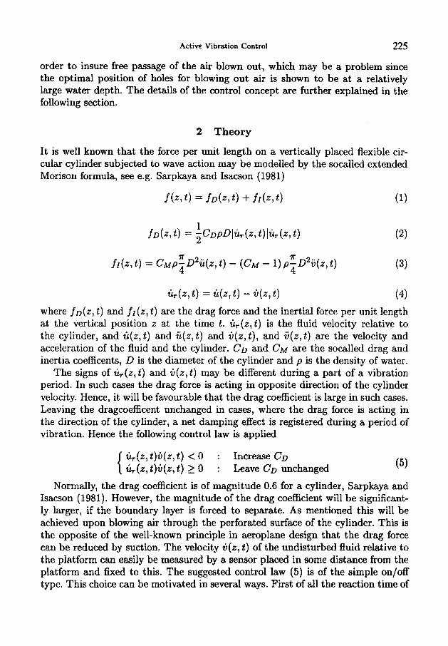
2 Theory
It is well known that the force per unit length on a vertically placed flexible cir- cular cylinder subjected to wave action may be modelled by the socalled extended Morison formula, see e.g. Sarpkaya and Isacson (1981)
f(z1 t ) = f d z , t ) + f d z , t ) (1)
L
lr 7r fr(z, t ) = cMp-D2ii(z, t ) - ( C M - 1) p-D2ij(z, t )
4 4 (3)
where fo(z, t ) and fr(z, t ) are the drag force and the inertial force per unit length at the vertical position z at the time t . zl,(z,t) is the fluid velocity relative to the cylinder, and t i ( z , t ) and i i ( z , t ) and iI(z,t), and ij(z,t) are the velocity and acceleration of the fluid and the cylinder. CD and CM are the socalled drag and inertia coefficents, D is the diameter of the cylinder and p is the density of water.
The signs of 2ir(z,t) and iI(z, t) may be different during a part of a vibration period. In such cases the drag force is acting in opposite direction of the cylinder velocity. Hence, it will be favourable that the drag coefficient is large in such cases. Leaving the dragcoefficent unchanged in cases, where the drag force is acting in the direction of the cylinder, a net damping effect is registered during a period of vibration. Hence the following control law is applied
( 5 ) &(z, t)C(z, t ) < 0 : Increase CD { iir(zl t )C(z , t ) 2 0 : Leave CD unchanged
Normally, the drag coefficient is of magnitude 0.6 for a cylinder, Sarpkaya and Isacson (1981). However, the magnitude of the drag coefficient will be significant- ly larger, if the boundary layer is forced to separate. As mentioned this will be achieved upon blowing air through the perforated surface of the cylinder. This is the opposite of the well-known principle in aeroplane design that the drag force can be reduced by suction. The velocity +(z, t ) of the undisturbed fluid relative to the platform can easily be measured by a sensor placed in some distance from the platform and fixed to this. The suggested control law (5 ) is of the simple on/off type. This choice can be motivated in several ways. First of all the reaction time of
226 S.R.K. Nielsen, P.H. Kirkegaard and L. Thesbjerg
the valves are several orders of magnitude less than the fundamental eigenvibration period of the platform or the significant wave period, as well in the propotype as in the model scale. Secondly, only very little air (or water) need to be blown out, before the boundary layers separate. Hence, the control forces can be expected to work almost instantanously, when requested. This was also registrated during the model tests described below.
3 Description of experiments
The following section outlines the experiments which were performed in order to investigate the proposed control approach.
3.1 EXPERIMENTS IN FLOW CHANNEL
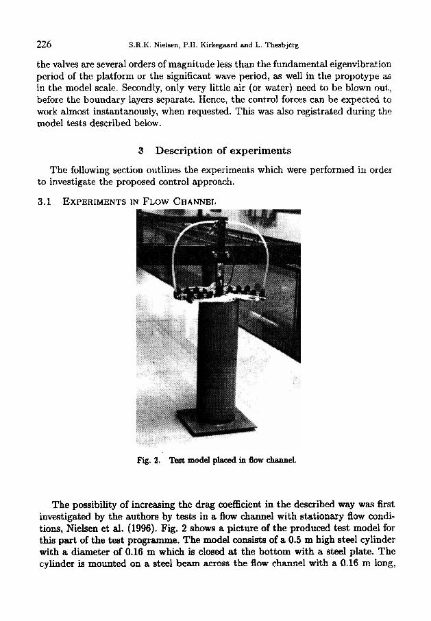
Fig. 2. Test model placed in flow channel.
The possibility of increasing the drag coefficient in the described way was first investigated by the authors by tests in a flow channel with stationary flow condi- tions, Nielsen et d. (1996). Fig. 2 shows a picture of the produced test model for this part of the teat programme. The model consists of a 0.5 m high steel cylinder with a diarrieter of 0.16 m which is closed at the bottom with a steel plate. The cylinder is mounted on a steel beam across the flow channel with a 0.16 m long,
Active Vibration Control 227
0.03 m width and 0.003 m thick steel plate. The cylinder is 0.2 and 0.24 m from the top of the cylinder perforated with 12 holes with equidistant distance, i.e the cylinder is perforated with 24 holes. Compressed air can be blown out of these holes since each hole is connected with a rubber tubing. It is possible to open and close each rubber tubing with a valve. All the 24 valves are placed on a connection box which is connected to one high-pressure rubber tubing having a manometer and a valve. This implies that it is possible to regulate the pressure of the air submitted to the connection box and to the 24 rubber tubings.
The test programme was divided into two parts. The first part without water in the flow channel consisted of eigenvibration tests in order to estimate the structural parameters of a single-degree-of-freedom (SDOF) model of the test setup. The second part of the test consisted of free decay tests with stationary water flow in the flow channel and different air pressure out of the holes in the cylinder. These tests were used to estimate the drag coefficient during flow conditions. The flow velocity was measured using an ultrasonic flow meter. The accelerations of the cylinder and the flow signal were both recorded using a data acquisition system based on a personal computer with an add-on A/D 16 bit simultaneous data acquisition board. The signals were sampled at 135 Hz with a time series length of 30 s. Notice, that since the undisturbed flow is stationary in this case, no attempt had been done to control the drag force according to ( 5 ) , i.e. the valves were opened throughout the free decay tests.
The tests were performed in a 2-dimensional flow channel. The water level was 0.355f0.01 m and the distance from the bottom of the cylinder to the lowest holes in the cylinder was 0.238 m. The free decay tests were performed by giving the cylinder a deflection corresponding to approximately the same value each time.
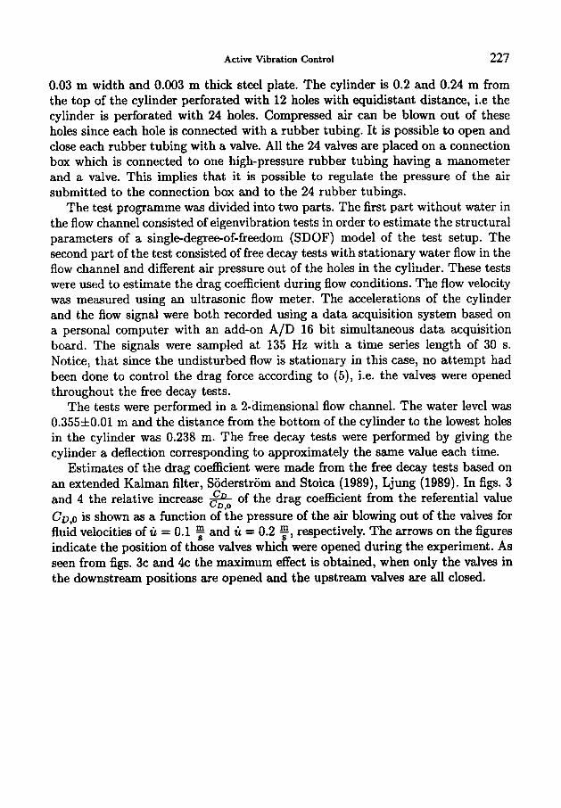
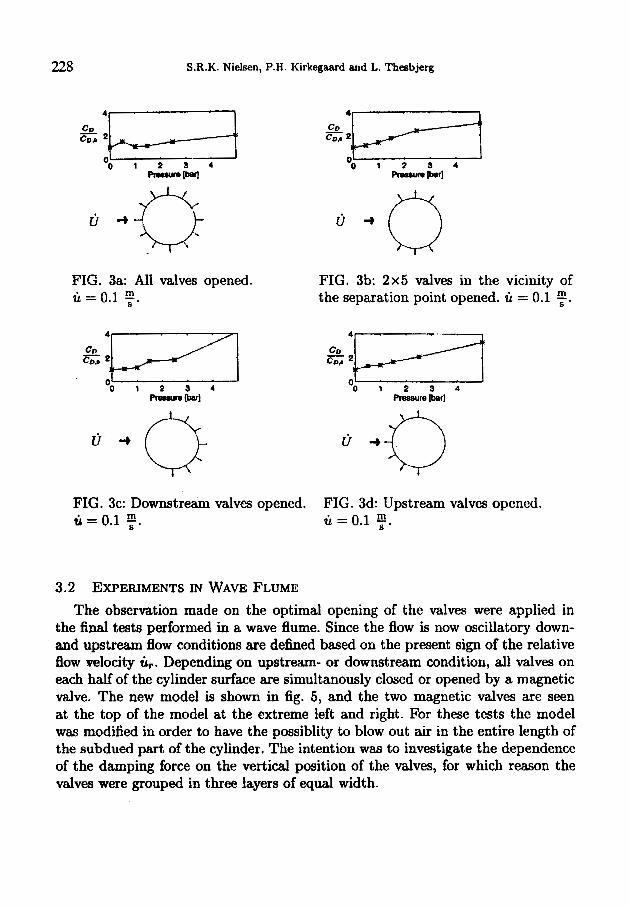
Estimates of the drag coefficient were made from the free decay tests based on an extended Kalman filter, Soderstrom and Stoica (1989), Ljung (1989). In figs. 3 and 4 the relative increase & of the drag coefficient from the referential value CD,O is shown as a function of the pressure of the air blowing out of the valves for fluid velocities of u = 0.1 and u = 0.2 F, respectively. The arrows on the figures indicate the position of those valves which were opened during the experiment. As seen from figs. 3c and 4c the maximum effect is obtained, when only the valves in the downstream positions are opened and the upstream valves are all closed.
228 S.R.K. Nielsen, P.H. Kirkegaard and L. Thesbjerg
FIG. 3a: All valves opened. m li = 0.1 7.
u
c o , 2 cD ‘B O O I 2 S 4
p- u+o FIG. 3b: 2x5 valves in the vicinity of the separation point opened. ti = 0.1 y.
L 8 1 2 3 4
Preosure mr]
FIG. 3c: Downstream valves opened. FIG. 3d: Upstream valves opened. ti =0.1 f . li = 0.1 f .
3.2 EXPERIMENTS IN WAVE FLUME The observation made on the optimal opening of t.,e valves were appliec in
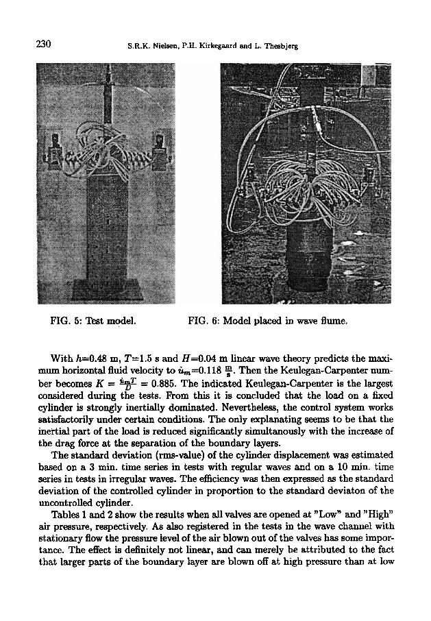
the final tests performed in a wave flume. Since the flow is now oscillatory down- and upstream flow conditions are defined based on the present sign of the relative flow velocity ti,. Depending on upstream- or downstream condition, all valves on each half of the cylinder surface are simultanously closed or opened by a magnetic valve. The new model is shown in fig. 5, and the two magnetic valves are seen at the top of the model at the extreme left and right. For these tests the model was modified in order to have the possiblity to blow out air in the entire length of the subdued part of the cylinder. The intention was to investigate the dependence of the damping force on the vertical position of the valves, for which reason the valves were grouped in three layers of equal width.
Active Vibration Control 229
" 0 1 2 3 4 -m
FIG. 4a: All valves opened. h = 0.2 y .
FIG. 4b: 2x5 valves in the vicinity of the separation point opened. u = 0.2 f .
1 co, cD 2b-+--t z2b---t 1
L O 0 1 2 3 4
Prescrure b r ]
FIG. 4c: Downstream valves opened. FIG. 4d: Upstream valves opened. ti = 0.2 y . u = 0.2 y .
Three tests were performed, one where the valves in all three layers were opened, one where the valves in the the two lowest layers were opened, and one where only the valves in the lowest layer were opened. Additionally, two tests were performed, where only the valves in the middle layer and the top layer opened. The eigenperiod of the test model in water was measured to TO = 1.25 s, the diameter of the cylinder was unchanged D=0.16 m, and the water depth in the flume was h = 0.48 m. Three different wave periods, T=0.7 s, 1.1 s, 1.5 s, and two different wave heights, H=0.02 m, 0.04m, were considered. Unfortunately, it was not possible to perform tests with larger wave periods or larger wave heights than indicated. The air was blown out at two different pressure levels, which will labelled "low" and "high", respectively. The air pressure was in both cases so low, that the gain of the vibration damping cannot be attributed to jet repulsion. The data acquisition was performed as for the stationary flow tests in the wave channel tests. Additionally some tests in irregular waves were performed.
230 S.R.K. Nielsen, P.H. Kirkegaard and L. Thesbjerg
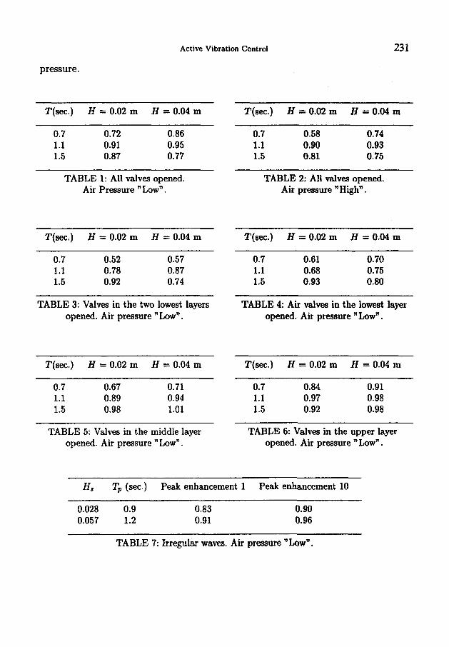
FIG. 5: Test model. FIG. 6: Model placed in wave flume.
With h=0.48 m, T=1.5 s and H=0.04 m linear wave theory predicts the maxi- mum horizontal fluid velocity to ic,=0.118 f. Then the Keulegan-Carpenter num- ber becomes K = = 0.885. The indicated Keulegan-Carpenter is the largest considered during the tests. F’rom this it is concluded that the load on a fixed cylinder is strongly inertially dominated. Nevertheless, the control system works satisfactorily under certain conditions. The only explanating seems to be that the inertial part of the load is reduced significantly simultanously with the increase of the drag force at the separation of the boundary layers.
The standard deviation (rms-value) of the cylinder displacement was estimated based on a 3 min. time series in tests with regular waves and on a 10 min. time series in tests in irregular waves. The efficiency was then expressed as the standard deviation of the controlled cylinder in proportion to the standard deviaton of the uncontrolled cylinder.
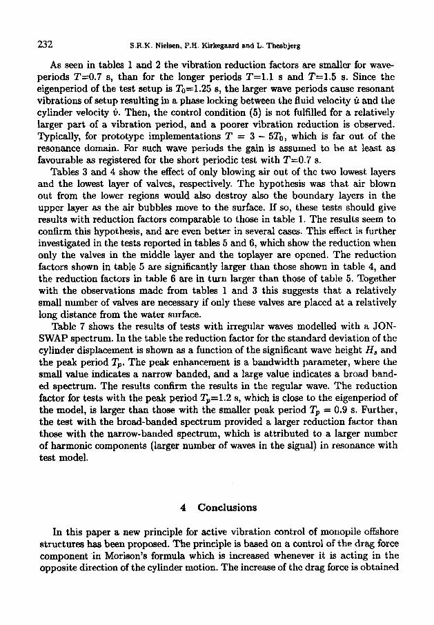
Tables 1 and 2 show the raults when all valves are opened at “Low” and ”High” air pressure, respectively. As also registered in the tests in the wave channel with stationary flow the pressure level of the air blown out of the valves has some impor- tance. The effect is definitely not linear, and can merely be attributed to the fact that larger parts of the boundary layer are blown off at high pressure than at low
Active Vibration Control 231
pressure.
T(sec.) H = 0.02 m H = 0.04 m T(sec.) H = 0.02 m H = 0.04 m
0.7 0.72 0.86 1.1 0.91 0.95 1.5 0.87 0.77
0.7 0.58 0.74 1.1 0.90 0.93 1.5 0.81 0.75
TABLE 1: All valves opened. Air Pressure " Low".
TABLE 2: All valves opened. Air pressure "High".
T(sec.) H = 0.02 m H = 0.04 m T(sec.) H = 0.02 m H = 0.04 m
0.7 0.52 0.57 1.1 0.78 0.87 1.5 0.92 0.74
TABLE 3: Valves in the two lowest layers opened. Air pressure " Low".
T(sec.) H = 0.02 m H = 0.04 m
0.7 0.67 0.71 1.1 0.89 0.94 1.5 0.98 1.01
TABLE 5: Valves in the middle layer opened. Air pressure "Low".
0.7 0.61 0.70 1.1 0.68 0.75 1.5 0.93 0.80
TABLE 4: Air valves in the lowest layer opened. Air pressure " Low".
"(set.) H = 0.02 m H = 0.04 m
0.7 0.84 0.91 1.1 0.97 0.98 1.5 0.92 0.98
TABLE 6: Valves in the upper layer opened. Air pressure "Low".
Hd T' (sec.) Peak enhancement 1 Peak enhancement 10
0.028 0.9 0.83 0.057 1.2 0.91
0.90 0.96
TABLE 7: Irregular waves. Air pressure "Low".
232 S.R.K. Nielsen, P.H. Kirkegaard and L. Theabjerg
As seen in tables 1 and 2 the vibration reduction factors are smaller for wave- periods T=0.7 s, than for the longer periods T=l.l s and T=1.5 s. Since the eigenperiod of the test setup is T0=1.25 s, the larger wave periods cause resonant vibrations of setup resulting in a phase locking between the fluid velocity ti and the cylinder velocity tj. Then, the control condition (5) is not fulfilled for a relatively larger part of a vibration period, and a poorer vibration reduction is observed. Typically, for prototype implementations T = 3 - 5T0, which is far out of the resonance domain. For such wave periods the gain is assumed to be at least as favourable as registered for the short periodic test with T=0.7 s.
Tables 3 and 4 show the effect of only blowing air out of the two lowest layers and the lowest layer of valves, respectively. The hypothesis was that air blown out from the lower regions would also destroy also the boundary layers in the upper layer as the air bubbles move to the surface. If so, these tests should give results with reduction factors comparable to those in table 1. The results seem to confirm this hypothesis, and are even better in several cases. This effect is further investigated in the tests reported in tables 5 and 6, which show the reduction when only the valves in the middle layer and the toplayer are opened. The reduction factors shown in table 5 are significantly larger than those shown in table 4, and the reduction factors in table 6 are in turn larger than those of table 5. Together with the observations made from tables 1 and 3 this suggests that a relatively small number of valves are necessary if only these valves are placed at a relatively long distance from the water surface.
Table 7 shows the results of tests with irregular waves modelled with a JON- SWAP spectrum. In the table the reduction factor for the standard deviation of the cylinder displacement is shown as a function of the significant wave height Hs and the peak period Tp. The peak enhancement is a bandwidth parameter, where the small value indicates a narrow banded, and a large value indicates a broad band- ed spectrum. The results confirm the results in the regular wave. The reduction factor for tests with the peak period Tp=1.2 s, which is close to the eigenperiod of the model, is larger than those with the smaller peak period Tp = 0.9 s. Further, the test with the broad-banded spectrum provided a larger reduction factor than those with the narrow-banded spectrum, which is attributed to a larger number of harmonic components (larger number of waves in the signal) in resonance with test model.
4 Conclusions
In this paper a new principle for active vibration control of monopile offshore structures has been proposed. The principle is based on a control of the drag force component 'in Morison's formula which is increased whenever it is acting in the opposite direction of the cylinder motion. The increase of the drag force is obtained
Active Vibration Control 233
forcing the boundary layers to separate upon blowing air through the surface of the subdued part of the cylinder.
In an initial test with a monopile model in a flow channel with stationary flow condition it was demonstrated that it is possible to increase the drag force in the indicated way. Further it was demonstrated that the optimal increase of the drag force is obtained when the valves in the wake of the flow is opened whereas the upstream valves are closed. Further, the increase depends on the pressure of the air.
Next, the testing was extended to oscillatory flow in a wave flume, where both regular and irregular plane wave conditions were considered. By the use of two magnetic valves the opening and closing af all valves on each half of the cylinder surface of the model were controlled based on the signs of the relative flow velocity and the velocity of the cylinder. Again, the results showed an increased effect in case of high pressure air compared to low pressure air conditions, which was attributed to the fact that larger parts of the .boundary layers are blown off at high air pressure. The reduction of vibrations is smaller for waves close tcu the eigenfiequency of the system, which is attributed to a phase locking of the fluid and cylinder velocities at resonance, so the control condition is very seldom invoked. It is demonstrated that the air blown out from the lower valves will also destroy the boundary layers at upper parts of the cylinder. horn this it is concluded that a relatively small number of valves are needed, and these should be placed relatively far from the free water surface. The results from tests in irregular sea states confirm the results obtained in regular waves. The system is working better in case the eigenperiod of the system is well separated from the dominating frequencies in the excitation around the peak period in the spectrum. Further, the tests seem to indicate that the applicability of the principle is not restricted to drag dominated systems, as may be anticipated at first sight. Actually the Keuligan-Charpenter numbers for the model setup were all below 0.885. The explanation can only be that the inertial force is reduced at the same time as the drag force is increased.
It should be noticed that the aim of the study has merely been to demonstrate the principle, and no consideration on the design of a possible full scale implemen- tation has been attempted. However, in such an implementation the advantage of the system is that the control forces are generated by the surrounding flow, so no external power supply besides that of maintaining the air pressure and opening and closure of the valves is needed. Further, the instrumentation of the system is rather limited. The disadvantage is that the cylinder must be kept free from marine growth at the position of the valves, which may be a problem if the opti- mal position of the holes at relatively large water depths is to be achieved.
234 S.R.K. Nielsen, P.H. Kirkegaard and L. Theabjerg
Acknowledgement
Support from the The Danish Technical Research Council within the project: "Damping Mechanisms in Dynamics of Structures and Materials" is gratefully acknowledged.
References
Ljung, L. 1989. System Identification - Theory for the User. Prentice Hall, Englewood Cliffs. Nielsen, S.R.K. and Kirkegaard, P.H. 1996. Active vibration control of a monopile offshore struc-
ture. Part one - pilot project. Aalborg University, Fracture and Dynamics, Paper No. 73, ISSN
Sarpkaya, T. and Isaacson, M. 1981. Mechanics of Wave Forces on Oflshore Structures. Van
Soong, T.T. 1990. Active Structural Control: Theory and Practice. Longman Scientific and Tech-
Soderstrom, T. and Stoica, P. 1987. System Identification. Prentice Hall, Englewood Cliffs. Thesbjerg, L. 1992 Optimal Vibration Control of Civil Engineering Structures. Ph.D thesis, Aal-
1395-7953 R9609.
Nostrand Reinhold Company.
nical.
borg University.


![Aalborg Universitet Active Vibration Control of a Monopile ... · vibration control of civil engineering structures can be done using different techniques, see e.g. Soong et al. [1]](https://img.pdfslide.us/doc/110x75/5fd0630b35976e205815ee3e/aalborg-universitet-active-vibration-control-of-a-monopile-vibration-control.jpg)