Embed Size (px)
Citation preview
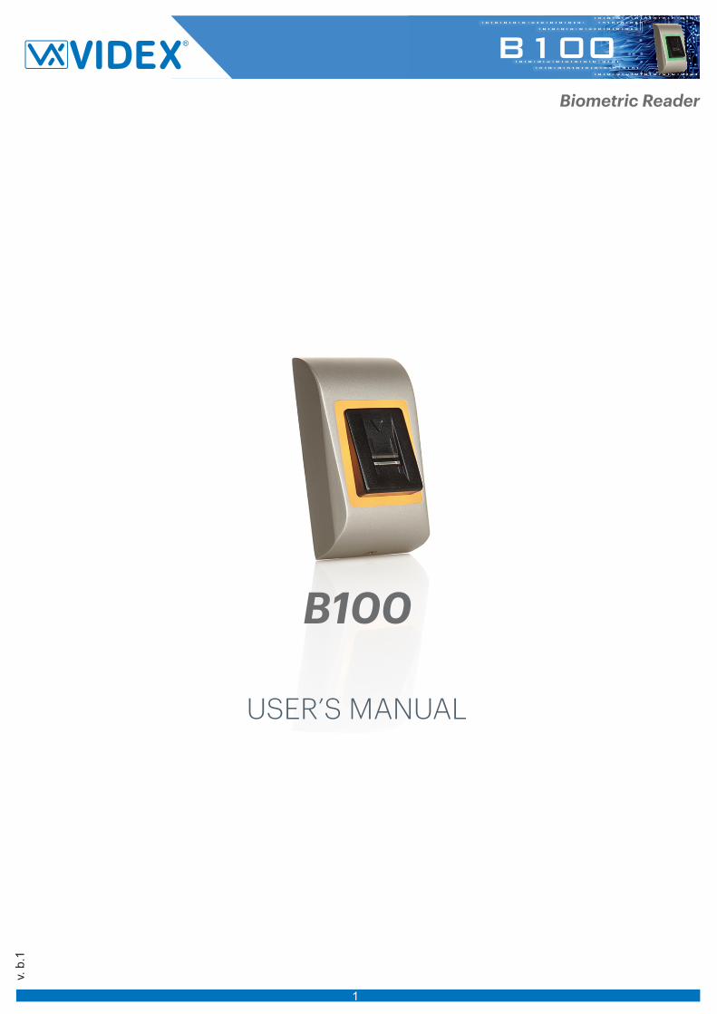
USER’S MANUAL
v. b
.1
B100 Biometric Reader
1
B100
1. DESCRIPTION
2. SPECIFICATIONS
3. MOUNTING
4. WIRING
5. CONNECTING BIOMETRIC READERS TO EWS CONTROLLER
5.1 CONNECTING BIOMETRIC READERS IN SAME RS485 LINE WITH THE EWS CONTROLLERS
5.2 CONNECTING BIOMETRIC READERS WHEN ALL THE CONTROLLERS HAVE TCP/IP COMMUNICATION
5.3 RS485 TUNING
6. CONNECTING BIOMETRIC READERS TO 3RD PARTY CONTROLLER
6.1 CONVERTERS PIN DESCRIPTION
7. ENROLLMENT
8. CONFIGURING THE BIOMETRIC READERS IN PROS SOFTWARE
8.1 ADDING BIOMETRIC READER
8.2 ENROLLING FINGERPRINTS FROM A READER
8.3 ENROLLING FINGERPRINTS FROM DESKTOP READER
8.4 DELETING FINGERPRINTS
8.5 UPLOADING THE FINGERPRINTS TO THE BIOMETRIC READERS
8.6 FIRMWARE UPDATE
8.7 SEND CONFIGURATION
8.8 ADVANCED SETTINGS
9. CONFIGURING THE BIOMETRIC READERS IN BIOMANAGER
9.1 ADD PORTAL
9.2 ADD READER
9.3 EDIT READER
DELETE READER 9.4
9.5 ADD USER
9.6 DELETING FINGERPRINTS
9.7 UPLOADING THE FINGERPRINTS TO THE BIOMETRIC READERS
9.8 CUSTOM WIEGAND
10. WIEGAND PROTOCOL DESCRIPTION
11. SAFETY PRECAUTIONS
Contents
3
3
3
4
4
5
5
6
6
6
7
7
8
9
10
10
11
1111
1212
1213
13
1415
15
16
17
18
3
B100 is a Wiegand biometric reader for access control applications. It offers storage up to 100 fingerprints and programmable Wiegand Output (8 to 128 bits).Configuration of the readers and fingerprint enrollment is done through PC Software.Connection between the biometric readers is RS485 and it is used for fingerprint transfer and configuration.When used with third party controllers, the connection between the Biometric readers and the PC is done through a converter (CNV100-RS485 to RS232 or CNV200-RS485 to USB or CNV300-RS485 to TCP/IP). Only one converter is needed per system (one converter for 1, 2, 3...30, 31 Biometric readers)The tamper switch output can trigger the alarm system, if an attempt is made to open or remove the unit from the wall.
The sensor incorporates dedicated sensing hardware to facilitate the detection of “spoofing” attacks based on fake fingers. This
data is embedded into the image data stream, and is processed on the processor. The system is capable of detecting and
defeating well-known fake finger mechanisms, such as molded “gummy” fingers.
The coating on the surface of the TouchChip sensor provides protection from scratching and abrasion due to normal contact
with fingertips and any incidental contact with fingernails.
1. DESCRIPTION
2

2. SPECIFICATIONS
Technology
Authentication
Interface
Protocol programming
Fingerprint Sensor Type
1:1000 identification time
Fingerprint enrolment
Green and Red LED
Orange LED
Buzzer ON/OFF
Consumption
Power supply
IP Rating
Operating Temperature
Dimensions (mm)
Biometry
Finger
Wiegand 8 to 128 bits; Default: Wiegand 26bit
By PROS CS software (EWS system) and BIOMANAGER (all access control systems)
Swipe Capacitive
970 msec, including feature extraction time
On the reader or from the USB desktop reader
Externally Controlled
Idle mode
Yes
100mA
65
9-14V DC
-20°C to +50°C
91 x 51 x 25
Storage/Operating Humidity
Colour
5% to 93% RH without condensation
Silver, Red, Green, Dark Grey, Blue, White
Cable distance 50m
Backlight ON/OFF Yes
Fingerprint capacity up to 100 fingerprints
Fingerprints per user 1-10 fingerprints
Tamper Yes
3. MOUNTING
4.1.
Cable
Ø6.0(3NoS)
30m
m
5mm
2.
3 (3 x 30mm)
3.
1 (M3 x 6mm)
MC-MINI
If the biometric reader is installed and used outdoor, the reader MUST be fitted with the MC-MINI metal cover available in our accessories in order to protect the sensor from direct rainfall. The operating temperature of the product is between -20ºC - + 50ºC. If the reader is installed in an environment where the temperature can drop below -10ºC or/and if the sensor could only be exposed to direct sunlight, it is strongly recommended to install the reader inside a third party sealed wall mount box (fitted with additional heater if very low temperature) to keep a constant sensor level performance. Videx™ cannot guarantee the functionality of the product if measures and advice before are not followed. It is also strongly recommended to use double technology biometric readers when use outdoor to offer first higher security but also the possibility to use different readers depending on users.
4. WIRING
12V DC
GND
Tamper
Tamper Tamper Switch(NO)
9-14V DC
ground
D1
D0
Data 1
Data 0
LR- Red LED -
LG- Green LED -
A
B
RS485 A
RS485 B
Tamper Switch(NO)
LR-
D1
D0
TampBlue
Yellow
RedBlackPinkViolet
Orange
Gray
White
LG-
RS485
Green
12V DC
GNDA
B
WIEGAND
3
RS485
1 km max / 32 Units (EWS + Biometric Readers)TCP/IPgnd gnd
Stubmax. 5m
Jumper for RS485 termination
5.1 CONNECTING BIOMETRIC READERS IN SAME RS485 LINE WITH THE EWS CONTROLLERS
The Biometric readers are connected through RS485 bus. The same RS485 bus that the EWS controllers are connected to. Maximum units in one network (EWS + Biometric readers) is 32. If there are more than 32 units in one network, please utilize RS 485 HUB to connect. The RS485 Line should be configured in the form of a daisy chain, NOT in a form of a star. If star must be used in some points,
keep the stubs from the RS485 backbone as short as possible. Maximum length of the stub is dependant of the installation (total number of devices in RS485 line (total cable length, termination, cable type...) so recommendation is to keep stubs shorter than 5 meters, keeping in mind that this can be possible reason for errors in communication with PC software
The cable must be twisted and shielded with a min. 0.2 mm2 cross section. Connect the ground (0V) of each unit in the RS 485 Line using a third wire in the same cable. The shield of the communication cable between two devices must be connected to the EARTH from ONE side of the RS 485
Line. Use the side that has earth connection to the building’s grounding network.
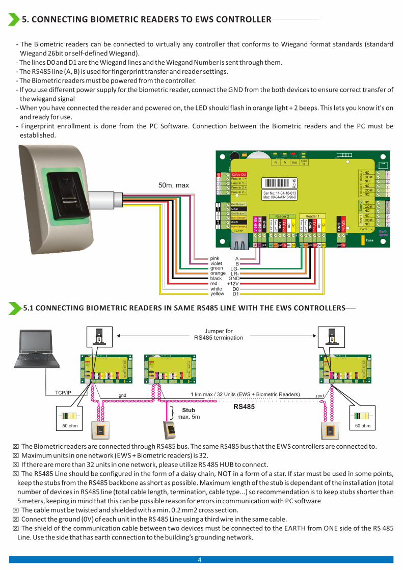
- The Biometric readers can be connected to virtually any controller that conforms to Wiegand format standards (standard Wiegand 26bit or self-defined Wiegand).
- The lines D0 and D1 are the Wiegand lines and the Wiegand Number is sent through them.- The RS485 line (A, B) is used for fingerprint transfer and reader settings.- The Biometric readers must be powered from the controller. - If you use different power supply for the biometric reader, connect the GND from the both devices to ensure correct transfer of
the wiegand signal- When you have connected the reader and powered on, the LED should flash in orange light + 2 beeps. This lets you know it's on
and ready for use. - Fingerprint enrollment is done from the PC Software. Connection between the Biometric readers and the PC must be
established.
5. CONNECTING BIOMETRIC READERS TO EWS CONTROLLER
50 ohm 50 ohm
LD
16
R5
5
C41
C28
L2
R36
LD
20 R
18 R2
5
R2
4
C40
R1
0
C34
L10
L11
C1
8
C3
3
R9
C42
C1
R5
R4
5
C43
C44
R2
8
R2
1
C4
5
D13
LD
14
R4
6
C3
C5
R3
8
ZD3 C29
L9
LD
13
R14
ZD4C32
R19
R37
ALD17
ALD19
ALD18
L7
C27L6
C16
C15
RX
4
D5
D1
0
R32
R33
R35
R4
9
IC6
ZD
5
ZD
6
R22
L3
R5
3
R3
4
TAS1
IC11
R1
5
IC15
R3
R4
L8
R4
7
FUSE1
IC8
R20R1
6
R11
C2
X1
C4
IC7ICN2
R1
C13
C12
ICN1
R2
3
R4
8
ALD
5
RE
1R
E3A
LD
8
X3
IC1
C6
U5
L5
L4 RE
4R
E2A
LD
6A
LD
9
ZD2
LD
15
R13
ZD1
R54
R50
R6
IC12 R17
R7
R62
ALD23
D3
D2
RX
3
J1
Rb6
R2
LD
21
IC2
H1 ALD22
BAT
U1 IC5
FUSE2
IC3
U4
A A
IC1
A
A AA
Earthscrew
Fre
e L
ed 1
Fre
e L
ed 2
GN
D
12
V o
ut
D0
D1
Fre
e L
ed 1
Fre
e L
ed 2
GN
D
12
V o
ut
D0
D1
Door Sensor2
Door Sensor1
Exit Button1
Exit Button2
GND
GND
Free In 2 -
Free In 2 +
Free In 1 -
Free In 1 +
Rx Tx Busy System OK
Do
or
1D
oo
r 2
Fre
e O
ut 1
Fre
e O
ut 2
TCP/IPEarth
12Vdc Out
12VgndD1D012Vgndled2led1
12VIN
1
IN1
IN
2
IN2
+
-+
-
D1D012Vgndled2led1
PB
2P
B1
DS
2D
S1
gn
dg
nd C
OM
NC
1N
O1
NC
2N
O2
CO
MC
OM
NC
3N
O3
NC
4N
O4
CO
M
GN
D
BA gnd
Fuse
Ser No: 11-04-16-013Mac: 00-04-A3-16-90-D
Ro
HS
3 3 6 1 1 1 0 1 3 1
pinkviolet greenorangeblackredwhiteyellow
50m. max
B
+12V
LG-
D1D0
LR-GND
A
4

TCP/IP
50mmax.
50mmax.
50mmax.
Switch
When all the controllers are connected via TCP/IP, then the RS485 network becomes local (from Reader 1 to the Controller then to the Reader 2).
Connect the readers directly to the Rs485 terminals in each controller. If the distance Reader-Controller is high (50meters) and if the communication with the reader can not be established, then
terminate the RS485 network by closing the jumper in the EWS Controller or as described in chapter 4.
5.2 CONNECTING BIOMETRIC READERS WHEN ALL THE CONTROLLERS HAVE TCP/IP COMMUNICATION
5.3 RS485 TUNING
- Terminate both ends of the line with 120 Ohm resistor. If end of line is EWS, use built in resistor (120 ohm) by closing the jumper. - If the communica�on is not established and stable, use the external resistors provided in the hardware kit.
When using CAT 5 compa�ble cable, in most of the cases, termina�on made with 50 Ohm external resistor or combina�on of 50 Ohm external and termina�on resistor from the EWS (120 Ohm) should be the solu�on.
RS485 Termina�on resistors:
RS485
1 km max / 32 Units (EWS + Biometric Readers)TCP/IPgnd gnd
Stubmax. 5m
Jumper for RS485 termination
50 ohm 50 ohm
NOTE: This is recommended configuration when you have multiple biometric readers in the same network. In this configuration, NO TERMINATION resistors are required.When all the controllers have TCP/IP communication the biometric readers are easily wired. When the controllers have RS485 communication, it is difficult to maintain the daisy chain of the RS485 network. Wiring the biometric readers in that formation is a challenge. See the schematic diagram bellow.
RS485 RS485
5

6. CONNECTING BIOMETRIC READERS TO THIRD PARTY CONTROLLERS
Connect the lines D0, D1, Gnd and +12V to the third party controller. Connect the RS485 Line (A, B) to the converter. Connect the converter in the PC. Fingerprint enrollment is done from the PC Software. Connection between the Biometric readers and the PC must be established. The Biometric readers communicate with each other with a RS485 and with the PC Software through a Converter. The RS485 Line should be configured in the form of a daisy chain, NOT in a form of a star. Keep the stubs from the RS485 backbone
as short as possible (not more than 5 meters) Only one converter per installation is needed, not per reader.
Biometric Reader Converter
RS 485 A
RS 485 B
PIN 1 (RS 485 +)
PIN 2 (RS 485 -)
CNV100Converter RS485 to RS232Does not requires installation
CNV200Converter RS485 to USBRequires installation as USB serial device (refer to CNV200 Manual).
CNV300Converter RS485 to TCP/IPDoes not require installation. IP address set through Internet Browser(refer to CNV300 Manual)
6.1 CONVERTERS PIN DESCRIPTION
PIN 1
PIN 1PIN 1
BIOMANAGER Software
RS485 A
RS485 B
A
B
3rd party controller
- + D0 D1 - + D0 D1
3rd party controller
- + D0 D1 - + D0 D1
CNV100
CNV200
CNV300
BIOEUSB Desktop Reader
optional
7. ENROLLMENT
Follow the below instructions for correct finger swiping Starting from the first finger joint, place the selected finger on the swipe sensor and move it evenly towards oneself in one steady movement.
Result:For a valid swipe: Tricolour Status LED turns green + OK Beep(short + long beep)For an invalid or misread swipe: Tricolour Status LED turns red + Error Beep ( 3 short beeps)
CNV1000
CNV1000Converter RS485 to TCP/IPDoes not require installation. IP address set through Internet Browser
6
8. CONFIGURING THE BIOMETRIC READERS IN PROS CS SOFTWARE
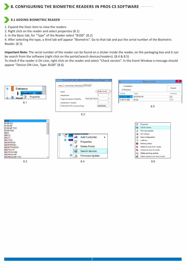
1. Expand the Door item to view the readers2. Right click on the reader and select properties (8.1)3. In the Basic tab, for “Type” of the Reader select “B100”. (8.2)4. After selecting the type, a third tab will appear “Biometric”. Go to that tab and put the serial number of the Biometric Reader. (8.3)
Important Note: The serial number of the reader can be found on a sticker inside the reader, on the packaging box and it can be search from the software (right click on the portal/search devices/readers). (8.4 & 8.5)To check if the reader is On Line, right click on the reader and select “Check version”. In the Event Window a message should appear “Device ON Line, Type: B100” (8.6)
BIOPAD-M
B100
8.1
8.2
8.3
8.4
8.5
8.6
8.1 ADDING BIOMETRIC READER
7
8.7
8.8
8.9
8.11
8.10
8.12
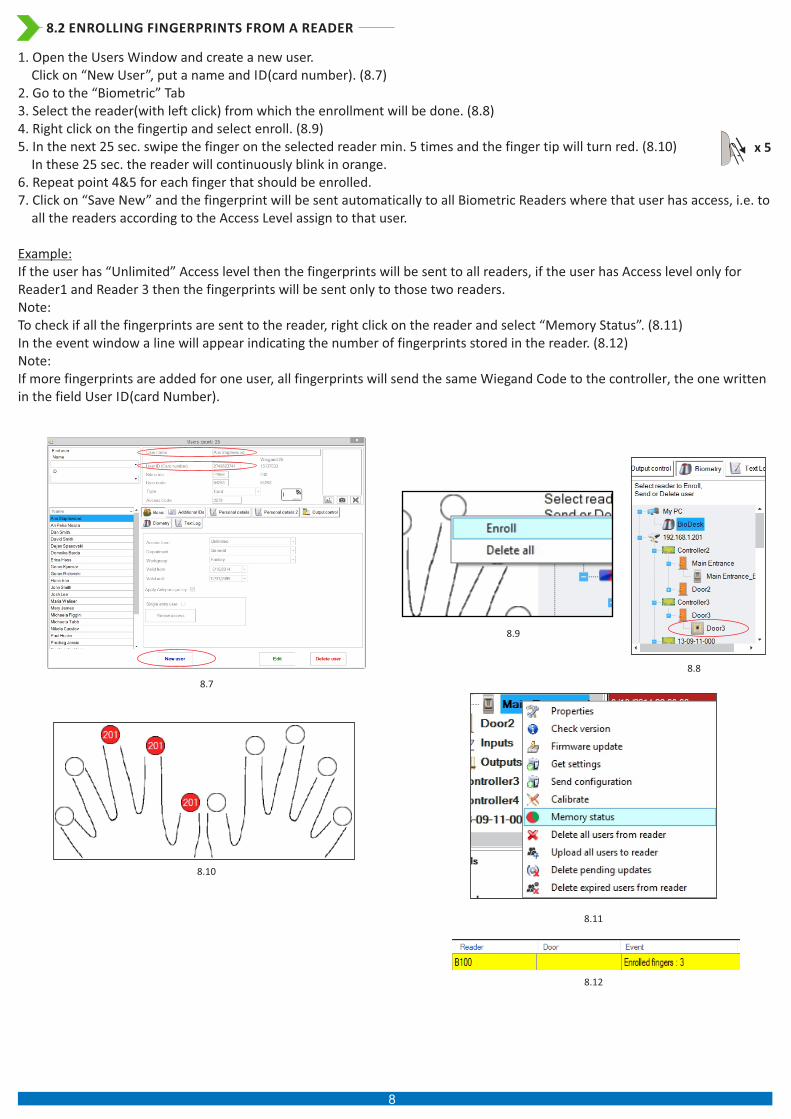
1. Open the Users Window and create a new user. Click on “New User”, put a name and ID(card number). (8.7)2. Go to the “Biometric” Tab3. Select the reader(with left click) from which the enrollment will be done. (8.8)4. Right click on the fingertip and select enroll. (8.9)5. In the next 25 sec. swipe the finger on the selected reader min. 5 times and the finger tip will turn red. (8.10) In these 25 sec. the reader will continuously blink in orange.6. Repeat point 4&5 for each finger that should be enrolled.7. Click on “Save New” and the fingerprint will be sent automatically to all Biometric Readers where that user has access, i.e. to
all the readers according to the Access Level assign to that user.
Example: If the user has “Unlimited” Access level then the fingerprints will be sent to all readers, if the user has Access level only for Reader1 and Reader 3 then the fingerprints will be sent only to those two readers.Note: To check if all the fingerprints are sent to the reader, right click on the reader and select “Memory Status”. (8.11)In the event window a line will appear indicating the number of fingerprints stored in the reader. (8.12)Note: If more fingerprints are added for one user, all fingerprints will send the same Wiegand Code to the controller, the one written in the field User ID(card Number).
8.2 ENROLLING FINGERPRINTS FROM A READER
x 5
8
8.3 ENROLLING FINGERPRINTS FROM DESKTOP READER
8.13
8.9
8.11
8.10
8.7
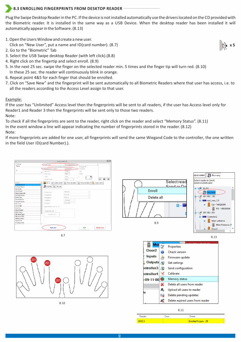
Plug the Swipe Desktop Reader in the PC. If the device is not installed automatically use the drivers located on the CD provided with the Biometric reader. It is installed in the same way as a USB Device. When the desktop reader has been installed it will automatically appear in the Software. (8.13)
1. Open the Users Window and create a new user. Click on “New User”, put a name and ID(card number). (8.7)2. Go to the “Biometric” Tab3. Select the USB Swipe desktop Reader (with left click).(8.8)4. Right click on the fingertip and select enroll. (8.9)5. In the next 25 sec. swipe the finger on the selected reader min. 5 times and the finger tip will turn red. (8.10) In these 25 sec. the reader will continuously blink in orange.6. Repeat point 4&5 for each finger that should be enrolled.7. Click on “Save New” and the fingerprint will be sent automatically to all Biometric Readers where that user has access, i.e. to
all the readers according to the Access Level assign to that user.
Example: If the user has “Unlimited” Access level then the fingerprints will be sent to all readers, if the user has Access level only for Reader1 and Reader 3 then the fingerprints will be sent only to those two readers.Note: To check if all the fingerprints are sent to the reader, right click on the reader and select “Memory Status”. (8.11)In the event window a line will appear indicating the number of fingerprints stored in the reader. (8.12)Note: If more fingerprints are added for one user, all fingerprints will send the same Wiegand Code to the controller, the one written in the field User ID(card Number).).
x 5
9
8.14
8.15
8.16
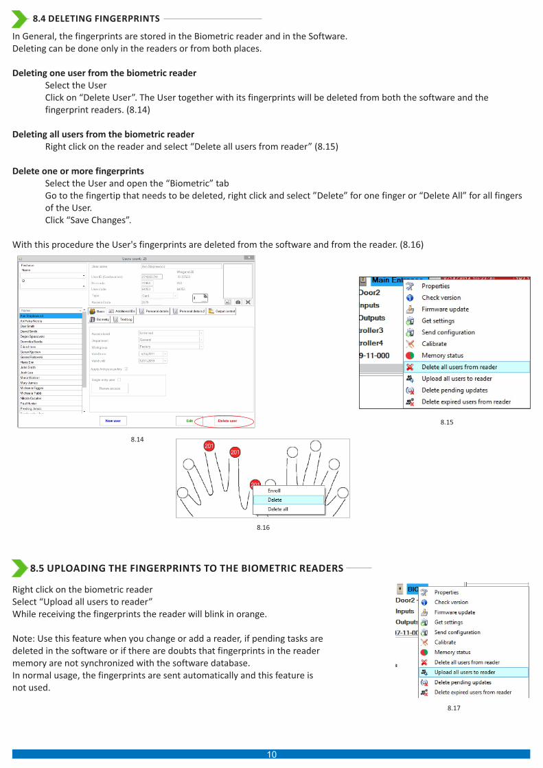
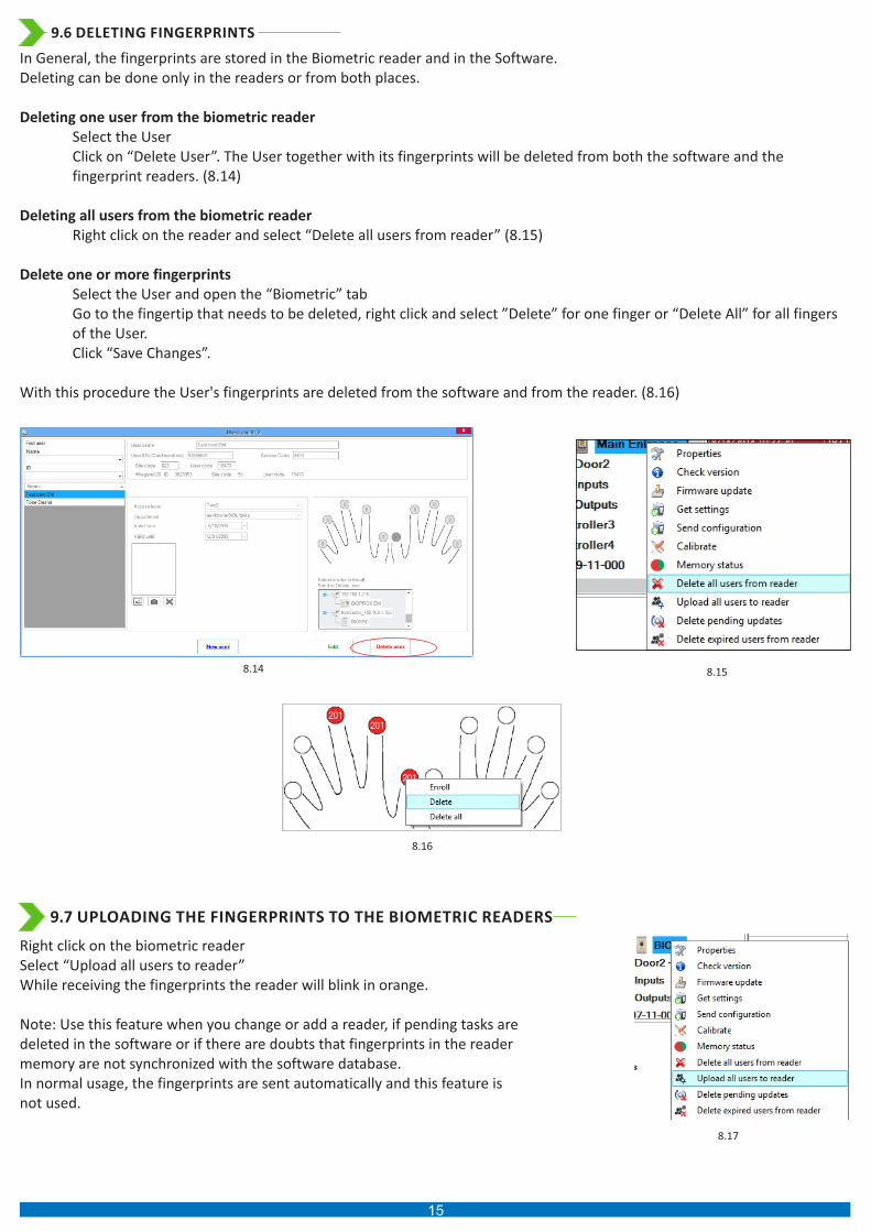
In General, the fingerprints are stored in the Biometric reader and in the Software.Deleting can be done only in the readers or from both places.
Deleting one user from the biometric reader Select the User Click on “Delete User”. The User together with its fingerprints will be deleted from both the software and the
fingerprint readers. (8.14)
Deleting all users from the biometric reader Right click on the reader and select “Delete all users from reader” (8.15)
Delete one or more fingerprints Select the User and open the “Biometric” tab Go to the fingertip that needs to be deleted, right click and select ”Delete” for one finger or “Delete All” for all fingers
of the User. Click “Save Changes”.
With this procedure the User's fingerprints are deleted from the software and from the reader. (8.16)
8.4 DELETING FINGERPRINTS
Right click on the biometric readerSelect “Upload all users to reader”While receiving the fingerprints the reader will blink in orange.
Note: Use this feature when you change or add a reader, if pending tasks are deleted in the software or if there are doubts that fingerprints in the reader memory are not synchronized with the software database.In normal usage, the fingerprints are sent automatically and this feature is not used.
8.17
8.5 UPLOADING THE FINGERPRINTS TO THE BIOMETRIC READERS
10
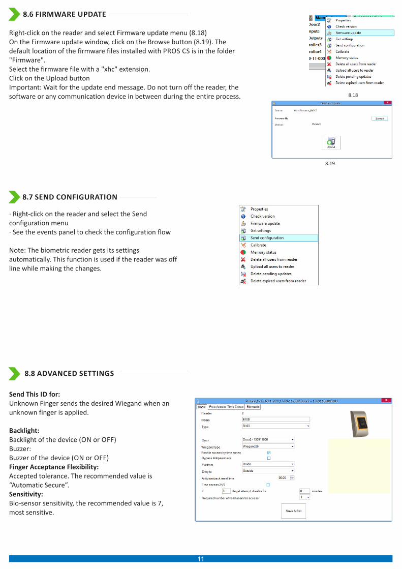
Right-click on the reader and select Firmware update menu (8.18)On the Firmware update window, click on the Browse button (8.19). The default location of the firmware files installed with PROS CS is in the folder "Firmware".Select the firmware file with a "xhc" extension.Click on the Upload buttonImportant: Wait for the update end message. Do not turn off the reader, the software or any communication device in between during the entire process. 8.18
8.6 FIRMWARE UPDATE
· Right-click on the reader and select the Send configuration menu· See the events panel to check the configuration flow
Note: The biometric reader gets its settings automatically. This function is used if the reader was off line while making the changes.
8.7 SEND CONFIGURATION
Send This ID for:Unknown Finger sends the desired Wiegand when an unknown finger is applied.
Backlight: Backlight of the device (ON or OFF)Buzzer:Buzzer of the device (ON or OFF)Finger Acceptance Flexibility: Accepted tolerance. The recommended value is “Automatic Secure”.Sensitivity: Bio-sensor sensitivity, the recommended value is 7, most sensitive.
8.8 ADVANCED SETTINGS
8.19
11
9 CONFIGURING THE BIOMETRIC READERS IN BIOMANAGER
BIOMANAGER CS is software for fingerprint management of Videx Biometric readers, when used with third party access controllers.
Main functions:
- Fingerprint EnrollmentIt can be done by ANY Biometric reader in the network or by Desktop (USB) Biometric reader. Note: The Desktop Biometric reader BIOE is only compatible to Biometric readers with capacitive sensor, not with the ones with thermal sensor.- Fingerprint TransferFinger templates can be sent to any Reader in the Network. Different Users can be sent to different Biometric readers.- PIN Codes management and transferPIN Code length configuration (1 to 8 digits) and PIN Code transfer. - Wiegand Output ConfigurationThe Wiegand output of the Biometric reader can be customized bitwise.
9.2 ADD READER
Right-click on the portal connected to the reader and select Add reader
Fill the Reader formClick on Save and the reader icon appears under the selected portal
Right-click on reader and select Check Version
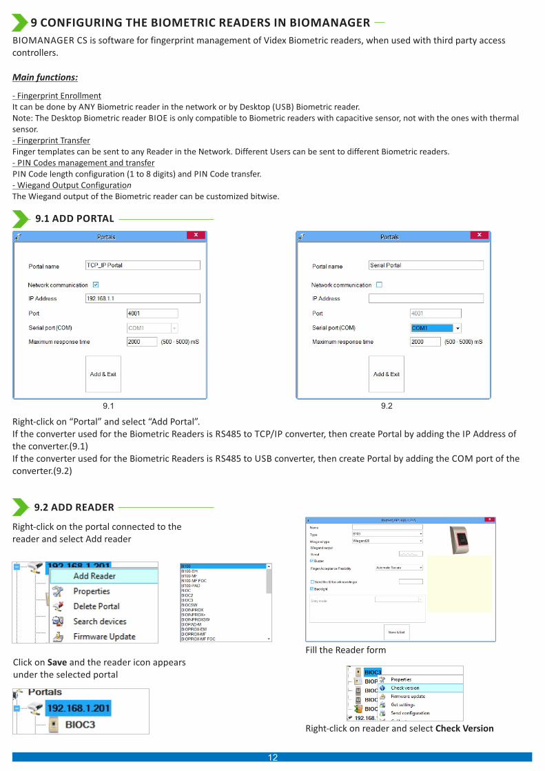
9.1 ADD PORTAL
Right-click on “Portal” and select “Add Portal”.If the converter used for the Biometric Readers is RS485 to TCP/IP converter, then create Portal by adding the IP Address of the converter.(9.1)If the converter used for the Biometric Readers is RS485 to USB converter, then create Portal by adding the COM port of the converter.(9.2)
9.1 9.2
12
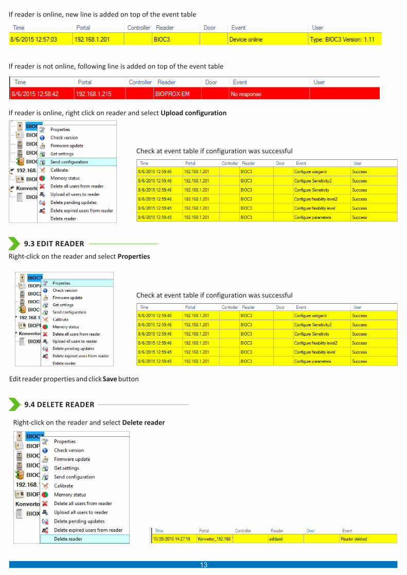
If reader is online, new line is added on top of the event table
If reader is not online, following line is added on top of the event table
If reader is online, right click on reader and select Upload configuration
Check at event table if configuration was successful
9.3 EDIT READER
Right-click on the reader and select Properties
Edit reader properties and click Save button
Check at event table if configuration was successful
9.4 DELETE READER
Right-click on the reader and select Delete reader
13

9.5 ADD USER
8.7 8.8
8.9
8.11
8.10
8.12
1. Open the Users Window and create a new user. Click on “New User”, put a name and ID(card number). (8.7)2. Select the reader(with left click) from which the enrollment will be done. (8.8)3. Right click on the fingertip and select enroll. (8.9)4. In the next 25 sec. swipe the finger on the selected reader min. 5 times and the finger tip will turn red. (8.10) In these 25 sec. the reader will continuously blink in orange.5. Repeat point 4&5 for each finger that should be enrolled.6. Click on “Save New” and the fingerprint will be sent automatically to all Biometric Readers where that user has access, i.e. to
all the readers according to the Access Level assign to that user.
Example: If the user has “Unlimited” Access level then the fingerprints will be sent to all readers, if the user has Access level only for Reader1 and Reader 3 then the fingerprints will be sent only to those two readers.Note: To check if all the fingerprints are sent to the reader, right click on the reader and select “Memory Status”. (8.11)In the event window a line will appear indicating the number of fingerprints stored in the reader. (8.12)Note: If more fingerprints are added for one user, all fingerprints will send the same Wiegand Code to the controller, the one written in the field User ID(card Number).
x 5
14
8.14 8.15
8.16
In General, the fingerprints are stored in the Biometric reader and in the Software.Deleting can be done only in the readers or from both places.
Deleting one user from the biometric reader Select the User Click on “Delete User”. The User together with its fingerprints will be deleted from both the software and the
fingerprint readers. (8.14)
Deleting all users from the biometric reader Right click on the reader and select “Delete all users from reader” (8.15)
Delete one or more fingerprints Select the User and open the “Biometric” tab Go to the fingertip that needs to be deleted, right click and select ”Delete” for one finger or “Delete All” for all fingers
of the User. Click “Save Changes”.
With this procedure the User's fingerprints are deleted from the software and from the reader. (8.16)
9.6 DELETING FINGERPRINTS
Right click on the biometric readerSelect “Upload all users to reader”While receiving the fingerprints the reader will blink in orange.
Note: Use this feature when you change or add a reader, if pending tasks are deleted in the software or if there are doubts that fingerprints in the reader memory are not synchronized with the software database.In normal usage, the fingerprints are sent automatically and this feature is not used.
8.17
9.7 UPLOADING THE FINGERPRINTS TO THE BIOMETRIC READERS
15

9.8 CUSTOM WIEGAND
BIOMANAGER CS has defined Wiegand 26, 30, 34, 40 bit as standard options and other 3 Wiegand settings as user definable.
To setup custom Wiegand formatSelect Wiegand menu from Settings
At Wiegand setup window select one from customs Wiegand
Set Wiegand parameter
Click on Save button
Note:Wiegand settings are out of scope for common end user. Please ask your installer to set the parameters and do not change it later.
For more information please refer to BIOMANAGER CS User Manual
16

10. WIEGAND PROTOCOL DESCRIPTION
The data is sent over the lines DATA 0 for the logic “0” and DATA 1 for the logic “1”. Both lines use inverted logic, meaning that a
pulse low on DATA 0 indicates a “0” and a pulse low on DATA 1 indicates a “1”.When the lines are high, no data is being sent. Only 1
of the 2 lines ( DATA 0 / DATA 1 ) can pulse at the same time.
Example: data 0010....
D0
D1
5V
0V
100 us
1 ms
0 0 1 0
5V
0V
Data bit 0 = approximately 100 us (microseconds)
Data bit 1 = approximately 100 us (microseconds)
Time between two data bits: approximately 1 ms (millisecond). Both data lines (D0 and D1) are high.
Description for the 26 bits Wiegand format
Each data block consists of a first parity bit P1, a fixed 8 bits header, 16 bits of user code and a 2nd parity bit P2. Such a data block is shown bellow:
Parity bit (bit 1) + 8 bits header + 16 bits user code = 2 bytes + Parity bit (bit 26)
P1 P2XXXXXXXX XXXXYYYY YYYYYYYY
Example: 170 31527
1 0 1 0 1 0 1 0 1 0 0 1 1 1 1 0 1 1 0 0 1 0 0 1 1 1
Note: Parity bits are calculated as follows:
P1 = even parity calculated over the bits 2 to 13 ( )X
P2 = odd parity calculated over the bits 14 to 25 ( )Y
E A A A A A A A A B B B B B B B B B B B B B B B B O
EvenParity
Bit
OddParity
BitSite Code User Code
17

11. SAFETY PRECAUTIONS
Do not install the device in a place subject to direct sun light without protective cover.Do not install the device and cabling close to a source of strong electro-magnetic fields like radio-transmitting antenna.Do not place the device near or above heating equipments.If cleaning, do not spray or splash water or other cleaning liquids but wipe it out with smooth cloth or towel.Do not let children touch the device without supervision.Note that if the sensor is cleaned by detergent, benzene or thinner, the surface will be damaged and the fingerprint can't be entered.
18

19

This product herewith complies with requirements of EMC directive 2014/30/EU. In addition it complies with RoHS directive EN50581:2012
20
Northern OfficeVidex Security LtdUnit 4-7 Chillingham ind EstNewcastle Upon TyneNE6 2XXTel: 0870 300 1240Fax: 0191 224 5678
Southern Office1 OspreyTrinity ParkTrinity WayLondonE4 8TDFax: 0208 523 5825