Embed Size (px)
Citation preview
Tutorial 02 Shear test on Composite rib panel. Use of RIVET elements. 1
A) Pre-processorA.1 ) Import geometry (IGES)A.2 ) Import the mesh / Generate the mesh
B) WorkshopB) WorkshopB.1 ) General model data...B.2 ) Material definition…B.3 ) Layup definition...B.4 ) Part definition...B.5 ) Stage definition... B.6 ) Group definition...B.7 ) Curves definition...B.8 ) Special sets
Shear test on Composite rib panel. Use of RIVET elements.
B.9 ) Element orientationC) CalculateD) Post-processor
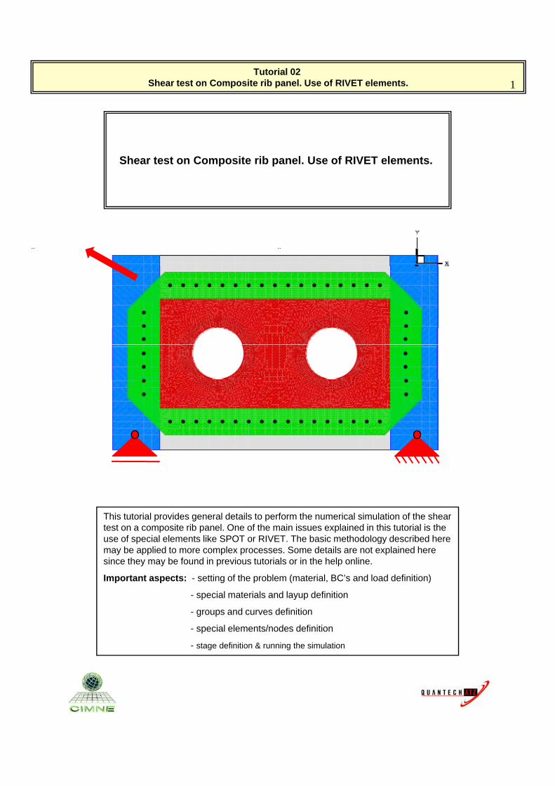
This tutorial provides general details to perform the numerical simulation of the shear test on a composite rib panel. One of the main issues explained in this tutorial is the
f i l l t lik SPOT RIVET Th b i th d l d ib d huse of special elements like SPOT or RIVET. The basic methodology described here may be applied to more complex processes. Some details are not explained here since they may be found in previous tutorials or in the help online.
Important aspects: - setting of the problem (material, BC’s and load definition)
- special materials and layup definition
- groups and curves definition
- special elements/nodes definitionp
- stage definition & running the simulation
Tutorial 02 Shear test on Composite rib panel. Use of RIVET elements. 2
A) Pre-processorA.1 ) Import geometry (IGES)A.2 ) Import the mesh / Generate the mesh
B) Workshop
This tutorial presents the basic methodology to be followed to prepare the simulation of the shear test on a composite rib panel, employing a steel frame as test rig. The panel and the frame are joined B) Workshop
B.1 ) General model data...B.2 ) Material definition…B.3 ) Layup definition...B.4 ) Part definition...B.5 ) Stage definition... B.6 ) Group definition...B.7 ) Curves definition...B.8 ) Special sets
g p jemploying special type of elements: the RIVETS.
The same methodology may then be applied to more complex geometries or processes.
The use of layers is fundamental to identify the parts that will be used in the simulation.
In this page it is explained the use of geometryB.9 ) Element orientationC) CalculateD) Post-processor
In this page it is explained the use of geometry layers.
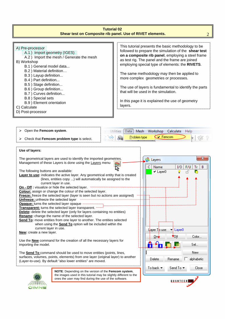
Open the Femcom system.
Check that Femcom problem type is select.
Use of layers:
The geometrical layers are used to identify the imported geometries. Management of these Layers is done using the Layers menu
The following buttons are available:Layer to use: indicates the active layer. Any geometrical entity that is created
(lines entities copy ) will automatically be assigned to the
Check that Femcom problem type is select.
(lines, entities copy ...) will automatically be assigned to thecurrent layer in use.
On - Off : visualize or hide the selected layer.Colour: assign or change the colour of the selected layer.Freeze: freeze the selected layer (layer is seen but no actions are assigned)Unfreeze: unfreeze the selected layerOpaque: turns the selected layer opaque Transparent: turns the selected layer transparent.Delete: delete the selected layer (only for layers containing no entities)Rename: change the name of the selected layer.Send To: move entities from one layer to another. The entities selected
when using the Send To option will be included within thecurrent layer in use.
New: create a new layer.
Use the New command for the creation of all the necessary layers for importing the model.
The Send To command should be used to move entities (points, lines, surfaces volumes points elements) from one layer (original layer) to anothersurfaces, volumes, points, elements) from one layer (original layer) to another (Layer-to-use). By default “also lower entities” are moved.
NOTE: Depending on the version of the Femcom system, the images used in this tutorial may be slightly different to the ones the user may find during the use of the software.
Tutorial 02 Shear test on Composite rib panel. Use of RIVET elements. 3
A) Pre-processorA.1 ) Import geometry (IGES)A.2 ) Import the mesh / Generate the mesh
B) Workshop
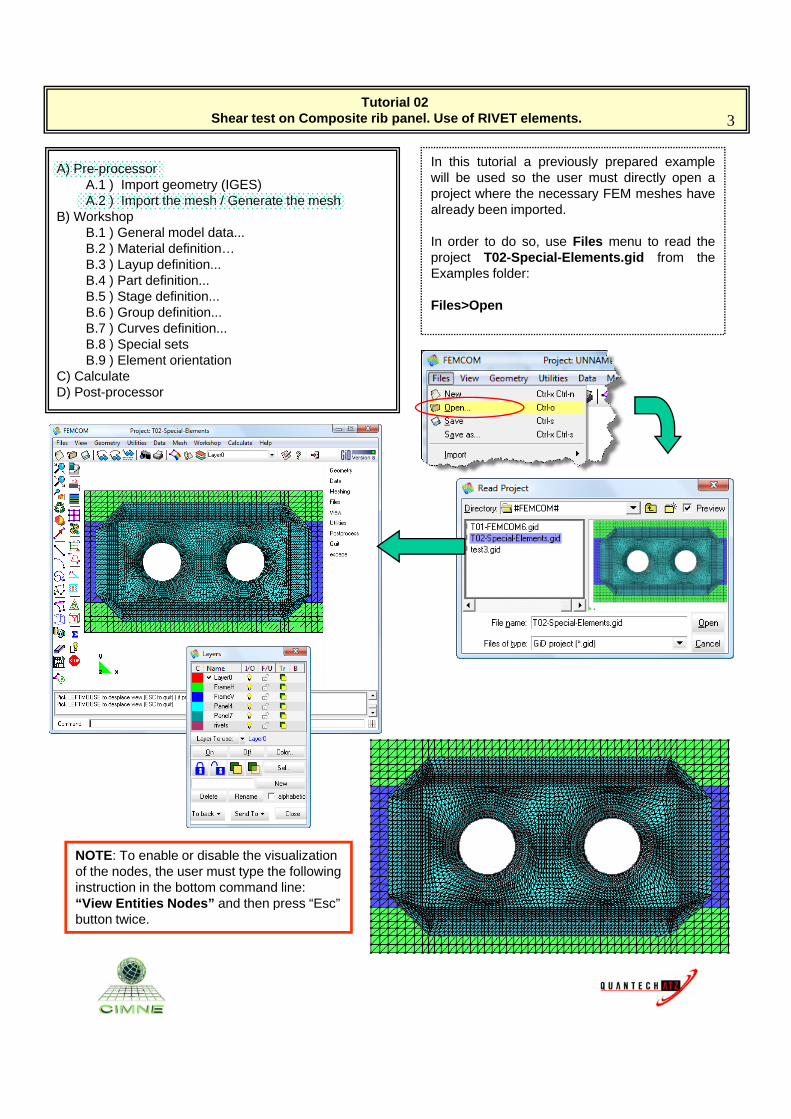
In this tutorial a previously prepared examplewill be used so the user must directly open aproject where the necessary FEM meshes havealready been imported.B) Workshop
B.1 ) General model data...B.2 ) Material definition…B.3 ) Layup definition...B.4 ) Part definition...B.5 ) Stage definition... B.6 ) Group definition...B.7 ) Curves definition...B.8 ) Special sets
In order to do so, use Files menu to read theproject T02-Special-Elements.gid from theExamples folder:
Files>Open
B.9 ) Element orientationC) CalculateD) Post-processor
NOTE: To enable or disable the visualization of the nodes, the user must type the following instruction in the bottom command line:“Vie Entities Nodes” and then press “Esc”“View Entities Nodes” and then press “Esc” button twice.
Tutorial 02 Shear test on Composite rib panel. Use of RIVET elements. 4
A) Pre-processorA.1 ) Import geometry (IGES)A.2 ) Import the mesh / Generate the mesh
B) Workshop
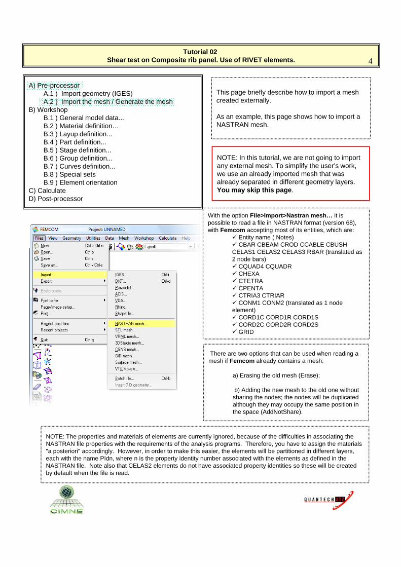
This page briefly describe how to import a mesh created externally.
B) WorkshopB.1 ) General model data...B.2 ) Material definition…B.3 ) Layup definition...B.4 ) Part definition...B.5 ) Stage definition... B.6 ) Group definition...B.7 ) Curves definition...B.8 ) Special sets
As an example, this page shows how to import a NASTRAN mesh.
NOTE: In this tutorial, we are not going to import any external mesh. To simplify the user’s work, we use an already imported mesh that was
B.9 ) Element orientationC) CalculateD) Post-processor
With the option File>Import>Nastran mesh… it is possible to read a file in NASTRAN format (version 68), with Femcom accepting most of its entities, which are:
Entity name ( Notes) CBAR CBEAM CROD CCABLE CBUSH
already separated in different geometry layers.You may skip this page.
CELAS1 CELAS2 CELAS3 RBAR (translated as 2 node bars) CQUAD4 CQUADR CHEXA CTETRA CPENTA CTRIA3 CTRIAR CONM1 CONM2 (translated as 1 node element) CORD1C CORD1R CORD1S CORD1C CORD1R CORD1S CORD2C CORD2R CORD2S GRID
There are two options that can be used when reading a mesh if Femcom already contains a mesh:
a) Erasing the old mesh (Erase);
NOTE: The properties and materials of elements are currently ignored, because of the difficulties in associating the NASTRAN file properties with the requirements of the analysis programs. Therefore, you have to assign the materials "a posteriori" accordingly. However, in order to make this easier, the elements will be partitioned in different layers,
h ith th PId h i th t id tit b i t d ith th l t d fi d i th
b) Adding the new mesh to the old one without sharing the nodes; the nodes will be duplicated although they may occupy the same position in the space (AddNotShare).
each with the name PIdn, where n is the property identity number associated with the elements as defined in the NASTRAN file. Note also that CELAS2 elements do not have associated property identities so these will be created by default when the file is read.
Tutorial 02 Shear test on Composite rib panel. Use of RIVET elements. 5
A) Pre-processorA.1 ) Import geometry (IGES)A.2 ) Import the mesh / Generate the mesh
B) Workshop
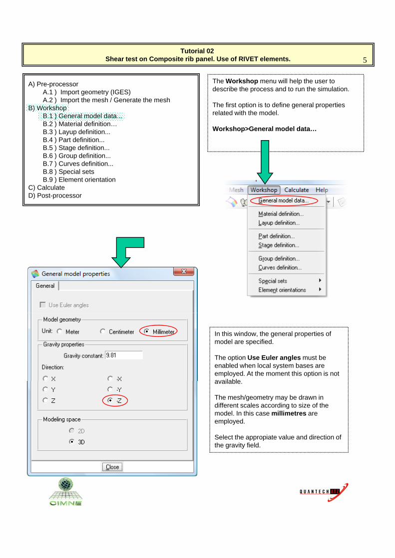
The Workshop menu will help the user to describe the process and to run the simulation.
The first option is to define general properties B) WorkshopB.1 ) General model data...B.2 ) Material definition…B.3 ) Layup definition...B.4 ) Part definition...B.5 ) Stage definition... B.6 ) Group definition...B.7 ) Curves definition...B.8 ) Special sets
p g p prelated with the model.
Workshop>General model data…
B.9 ) Element orientationC) CalculateD) Post-processor
In this window, the general properties of model are specified.
The option Use Euler angles must be enabled when local system bases are employed. At the moment this option is not availableavailable.
The mesh/geometry may be drawn in different scales according to size of the model. In this case millimetres are employed.
Select the appropiate value and direction of the gravity field.
Tutorial 02 Shear test on Composite rib panel. Use of RIVET elements. 6
A) Pre-processorA.1 ) Import geometry (IGES)A.2 ) Import the mesh / Generate the mesh
B) Workshop
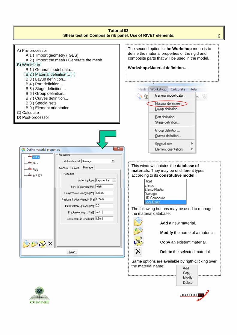
The second option in the Workshop menu is to define the material properties of the rigid and composite parts that will be used in the model.
B) WorkshopB.1 ) General model data...B.2 ) Material definition…B.3 ) Layup definition...B.4 ) Part definition...B.5 ) Stage definition... B.6 ) Group definition...B.7 ) Curves definition...B.8 ) Special sets
Workshop>Material definition…
B.9 ) Element orientationC) CalculateD) Post-processor
This window contains the database of materials. They may be of different types according to its constitutive model:
The following buttons may be used to manage the material database:
Add a new material.
Modify the name of a material.
Copy an existent material.
Delete the selected material.
Same options are available by rigth-clicking over the material name:
Tutorial 02 Shear test on Composite rib panel. Use of RIVET elements. 7
A) Pre-processorA.1 ) Import geometry (IGES)A.2 ) Import the mesh / Generate the mesh
B) Workshop
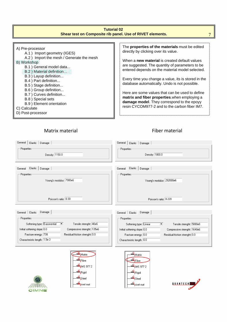
The properties of the materials must be edited directly by clicking over its value.
When a new material is created default values B) WorkshopB.1 ) General model data...B.2 ) Material definition…B.3 ) Layup definition...B.4 ) Part definition...B.5 ) Stage definition... B.6 ) Group definition...B.7 ) Curves definition...B.8 ) Special sets
are suggested. The quantity of parameters to be entered depends on the material model selected.
Every time you change a value, its is stored in the database automatically. Undo is not possible.
Here are some values that can be used to define matrix and fiber properties.when employing a damage model They correspond to the epoyyB.9 ) Element orientation
C) CalculateD) Post-processor
damage model. They correspond to the epoyy resin CYCOM977-2 and to the carbon fiber IM7.
Matrix material Fiber material
Tutorial 02 Shear test on Composite rib panel. Use of RIVET elements. 8
A) Pre-processorA.1 ) Import geometry (IGES)A.2 ) Import the mesh / Generate the mesh
B) Workshop
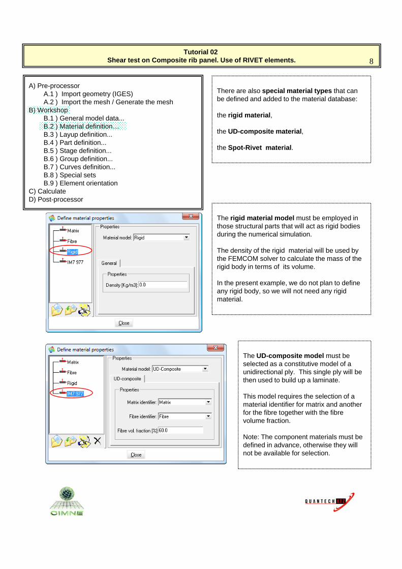
There are also special material types that can be defined and added to the material database:
B) WorkshopB.1 ) General model data...B.2 ) Material definition…B.3 ) Layup definition...B.4 ) Part definition...B.5 ) Stage definition... B.6 ) Group definition...B.7 ) Curves definition...B.8 ) Special sets
the rigid material,
the UD-composite material,
the Spot-Rivet material.
B.9 ) Element orientationC) CalculateD) Post-processor
The rigid material model must be employed in those structural parts that will act as rigid bodies during the numerical simulation.
The density of the rigid material will be used byThe density of the rigid material will be used by the FEMCOM solver to calculate the mass of the rigid body in terms of its volume.
In the present example, we do not plan to define any rigid body, so we will not need any rigid material.
The UD-composite model must be selected as a constitutive model of a unidirectional ply. This single ply will be then used to build up a laminate.
This model requires the selection of a material identifier for matrix and another for the fibre together with the fibre volume fraction.
Note: The component materials must be defined in advance, otherwise they will not be available for selection.
Tutorial 02 Shear test on Composite rib panel. Use of RIVET elements. 9
A) Pre-processorA.1 ) Import geometry (IGES)A.2 ) Import the mesh / Generate the mesh
B) Workshop
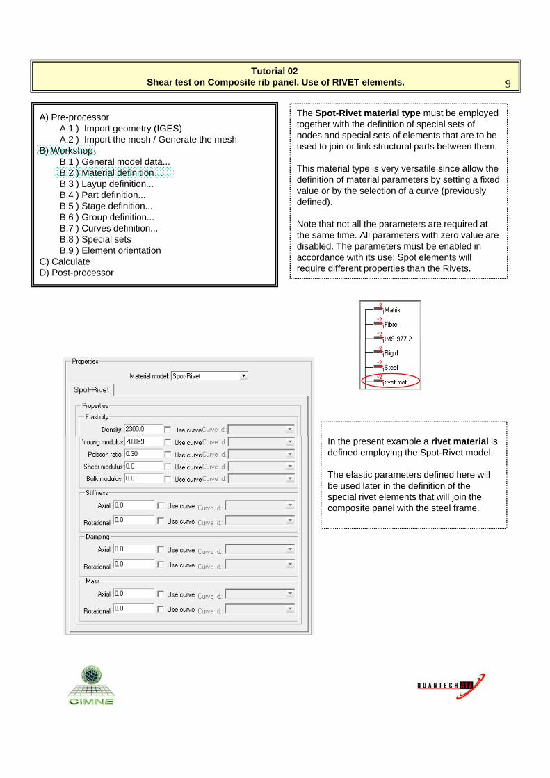
The Spot-Rivet material type must be employed together with the definition of special sets of nodes and special sets of elements that are to be used to join or link structural parts between them.B) Workshop
B.1 ) General model data...B.2 ) Material definition…B.3 ) Layup definition...B.4 ) Part definition...B.5 ) Stage definition... B.6 ) Group definition...B.7 ) Curves definition...B.8 ) Special sets
j p
This material type is very versatile since allow the definition of material parameters by setting a fixed value or by the selection of a curve (previously defined).
Note that not all the parameters are required at the same time. All parameters with zero value are disabled The parameters must be enabled inB.9 ) Element orientation
C) CalculateD) Post-processor
disabled. The parameters must be enabled in accordance with its use: Spot elements will require different properties than the Rivets.
In the present example a rivet material is defined employing the Spot-Rivet model.
The elastic parameters defined here will be used later in the definition of the special rivet elements that will join the composite panel with the steel frame.
Tutorial 02 Shear test on Composite rib panel. Use of RIVET elements. 10
A) Pre-processorA.1 ) Import geometry (IGES)A.2 ) Import the mesh / Generate the mesh
B) Workshop
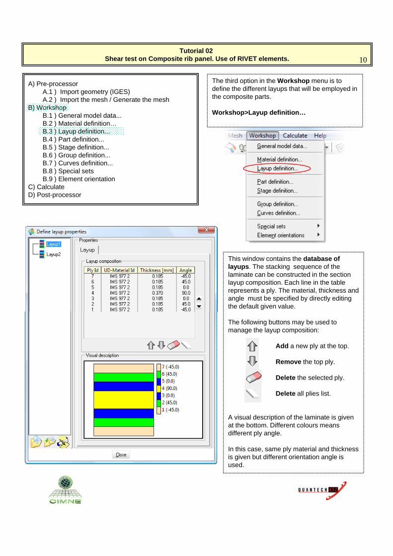
The third option in the Workshop menu is to define the different layups that will be employed in the composite parts.
B) WorkshopB.1 ) General model data...B.2 ) Material definition…B.3 ) Layup definition...B.4 ) Part definition...B.5 ) Stage definition... B.6 ) Group definition...B.7 ) Curves definition...B.8 ) Special sets
Workshop>Layup definition…
B.9 ) Element orientationC) CalculateD) Post-processor
This window contains the database of layups. The stacking sequence of the laminate can be constructed in the section layup composition. Each line in the table represents a ply. The material, thickness and angle must be specified by directly editing the default given value.
The following buttons may be used to manage the layup composition:
Add a new ply at the top.
Remove the top ply.
Delete the selected ply.Delete the selected ply.
Delete all plies list.
A visual description of the laminate is given at the bottom. Different colours means different ply angle.
I thi l t i l d thi kIn this case, same ply material and thickness is given but different orientation angle is used.
Tutorial 02 Shear test on Composite rib panel. Use of RIVET elements. 11
A) Pre-processorA.1 ) Import geometry (IGES)A.2 ) Import the mesh / Generate the mesh
B) Workshop
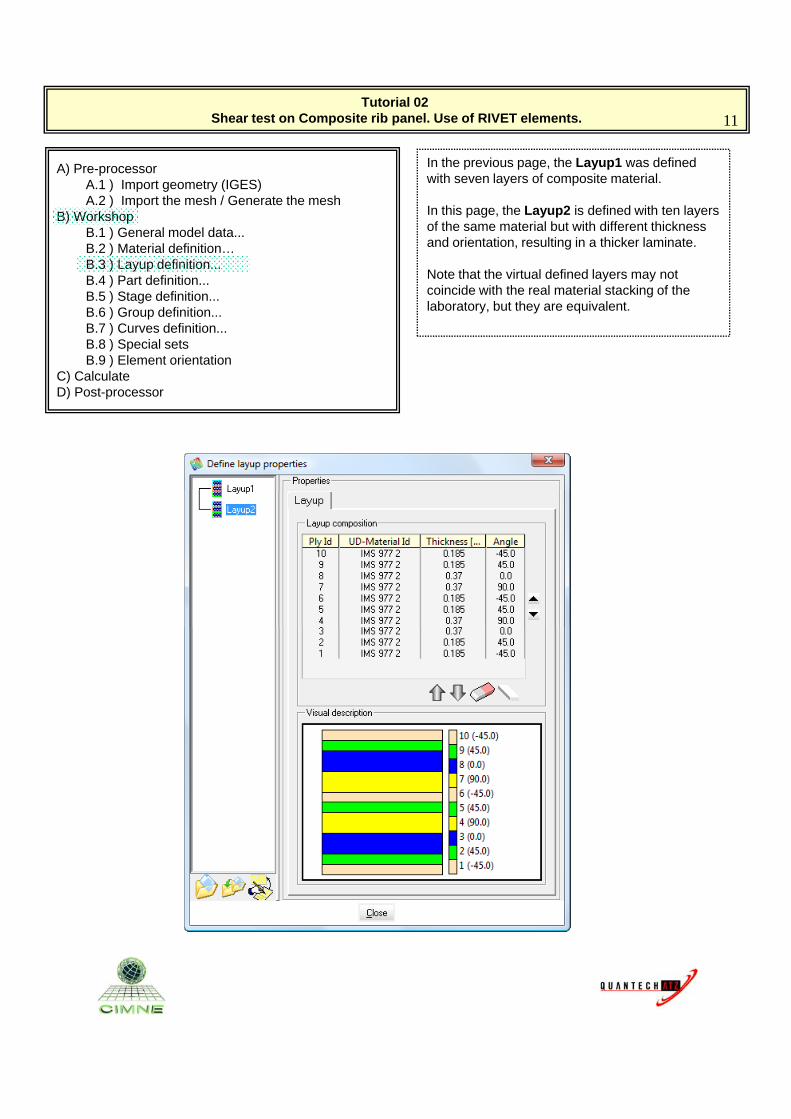
In the previous page, the Layup1 was defined with seven layers of composite material.
In this page, the Layup2 is defined with ten layers B) WorkshopB.1 ) General model data...B.2 ) Material definition…B.3 ) Layup definition...B.4 ) Part definition...B.5 ) Stage definition... B.6 ) Group definition...B.7 ) Curves definition...B.8 ) Special sets
p g y p yof the same material but with different thickness and orientation, resulting in a thicker laminate.
Note that the virtual defined layers may not coincide with the real material stacking of the laboratory, but they are equivalent.
B.9 ) Element orientationC) CalculateD) Post-processor
Tutorial 02 Shear test on Composite rib panel. Use of RIVET elements. 12
A) Pre-processorA.1 ) Import geometry (IGES)A.2 ) Import the mesh / Generate the mesh
B) Workshop
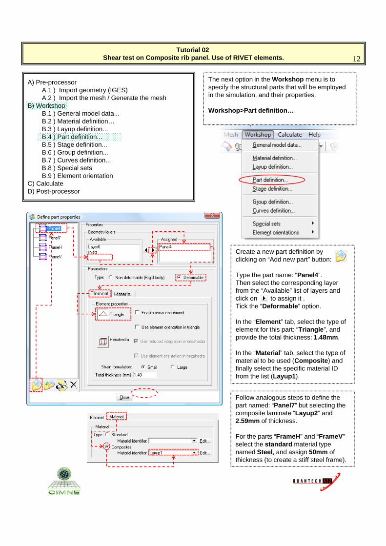
The next option in the Workshop menu is to specify the structural parts that will be employed in the simulation, and their properties.
B) WorkshopB.1 ) General model data...B.2 ) Material definition…B.3 ) Layup definition...B.4 ) Part definition...B.5 ) Stage definition... B.6 ) Group definition...B.7 ) Curves definition...B.8 ) Special sets
Workshop>Part definition…
B.9 ) Element orientationC) CalculateD) Post-processor
Create a new part definition by clicking on “Add new part” button:
Type the part name: “Panel4”.Then select the corresponding layer from the “Available” list of layers and click on “ ” to assign it .Tick the “Deformable” optionTick the Deformable option.
In the “Element” tab, select the type of element for this part: “Triangle”, and provide the total thickness: 1.48mm.
In the “Material” tab, select the type of material to be used (Composite) and finally select the specific material ID from the list (Layup1).
Follow analogous steps to define the part named: “Panel7” but selecting the composite laminate “Layup2” and 2.59mm of thickness.
For the parts “FrameH” and “FrameV” pselect the standard material type named Steel, and assign 50mm of thickness (to create a stiff steel frame).
Tutorial 02 Shear test on Composite rib panel. Use of RIVET elements. 13
A) Pre-processorA.1 ) Import geometry (IGES)A.2 ) Import the mesh / Generate the mesh
B) Workshop
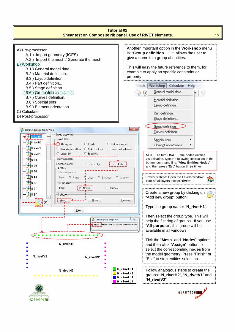
Another important option in the Workshop menu is: “Group definition…”. It allows the user to give a name to a group of entities.
B) WorkshopB.1 ) General model data...B.2 ) Material definition…B.3 ) Layup definition...B.4 ) Part definition...B.5 ) Stage definition... B.6 ) Group definition...B.7 ) Curves definition...B.8 ) Special sets
This will easy the future reference to them, for example to apply an specific constraint or property.
B.9 ) Element orientationC) CalculateD) Post-processor
NOTE: To turn ON/OFF the nodes entities visualization, type the following instruction in the bottom command line: “View Entities Nodes” and then press “Esc” button three times.
Previous steps: Open the Layers window:Turn off all layers except “rivets”.
Create a new group by clicking on “Add new group” button:
Type the group name: “N_rivetH1”.
Then select the group type. This will help the filtering of groups . If you use “All-purpose”, this group will beAll purpose , this group will be available in all windows.
Tick the “Mesh” and “Nodes” options, and then click “Assign” button to select the corresponding nodes from the model geometry. Press “Finish” or “Esc” to stop entities selection.
N_rivetH1
N_rivetV1 N_rivetV2
N_rivetH2 Follow analogous steps to create the groups: “N_rivetH2”, “N_rivetV1” and “N_rivetV2”.
Tutorial 02 Shear test on Composite rib panel. Use of RIVET elements. 14
A) Pre-processorA.1 ) Import geometry (IGES)A.2 ) Import the mesh / Generate the mesh
B) Workshop
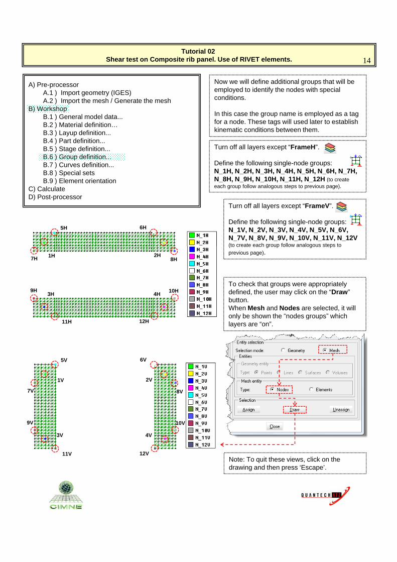
Now we will define additional groups that will be employed to identify the nodes with special conditions.
B) WorkshopB.1 ) General model data...B.2 ) Material definition…B.3 ) Layup definition...B.4 ) Part definition...B.5 ) Stage definition... B.6 ) Group definition...B.7 ) Curves definition...B.8 ) Special sets
In this case the group name is employed as a tag for a node. These tags will used later to establish kinematic conditions between them.
Turn off all layers except “FrameH”.
Define the following single-node groups:N_1H, N_2H, N_3H, N_4H, N_5H, N_6H, N_7H, N 8H N 9H N 10H N 11H N 12H (t tB.9 ) Element orientation
C) CalculateD) Post-processor
5H 6H
N_8H, N_9H, N_10H, N_11H, N_12H (to create each group follow analogous steps to previous page).
Turn off all layers except “FrameV”.
Define the following single-node groups:N_1V, N_2V, N_3V, N_4V, N_5V, N_6V, N_7V, N_8V, N_9V, N_10V, N_11V, N_12V (to create each group follow analogous steps to
1H 2H
3H 4H
7H 8H
9H 10HTo check that groups were appropriately defined, the user may click on the “Draw” button.When Mesh and Nodes are selected, it will only be shown the “nodes groups” which
(to create each group follow analogous steps to
previous page).
11H 12H
1V 2V
5V 6V
only be shown the nodes groups which layers are “on”.
3V 4V
11V 12V
7V 8V
9V 10V
Note: To quit these views, click on the drawing and then press ‘Escape’.
11V 12V
Tutorial 02 Shear test on Composite rib panel. Use of RIVET elements. 15
A) Pre-processorA.1 ) Import geometry (IGES)A.2 ) Import the mesh / Generate the mesh
B) Workshop
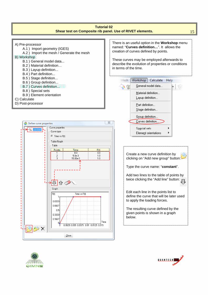
There is an useful option in the Workshop menu named: “Curves definition…”. It allows the creation of curves defined by points.
B) WorkshopB.1 ) General model data...B.2 ) Material definition…B.3 ) Layup definition...B.4 ) Part definition...B.5 ) Stage definition... B.6 ) Group definition...B.7 ) Curves definition...B.8 ) Special sets
These curves may be employed afterwards to describe the evolution of properties or conditions in terms of the time.
B.9 ) Element orientationC) CalculateD) Post-processor
Create a new curve definition by clicking on “Add new group” button:
T h “ ”Type the curve name: “constant”.
Add two lines to the table of points by twice clicking the “Add line” button:
Edit each line in the points list to define the curve that will be later used to apply the loading forces.to apply the loading forces.
The resulting curve defined by the given points is shown in a graph below.
Tutorial 02 Shear test on Composite rib panel. Use of RIVET elements. 16
A) Pre-processorA.1 ) Import geometry (IGES)A.2 ) Import the mesh / Generate the mesh
B) Workshop
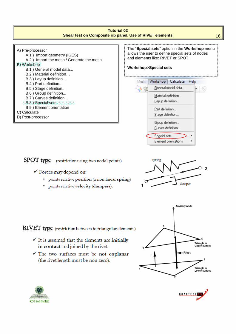
The “Special sets” option in the Workshop menu allows the user to define special sets of nodes and elements like: RIVET or SPOT.
B) WorkshopB.1 ) General model data...B.2 ) Material definition…B.3 ) Layup definition...B.4 ) Part definition...B.5 ) Stage definition... B.6 ) Group definition...B.7 ) Curves definition...B.8 ) Special sets
Workshop>Special sets
B.9 ) Element orientationC) CalculateD) Post-processor

Tutorial 02 Shear test on Composite rib panel. Use of RIVET elements. 17
A) Pre-processorA.1 ) Import geometry (IGES)A.2 ) Import the mesh / Generate the mesh
B) Workshop
The “Nodes sets definition…” option let the user define special sets of nodes, that are not already included in the parts or tools. For example, the set of auxiliary points required to define the rivets B) Workshop
B.1 ) General model data...B.2 ) Material definition…B.3 ) Layup definition...B.4 ) Part definition...B.5 ) Stage definition... B.6 ) Group definition...B.7 ) Curves definition...B.8 ) Special sets
y p qlocation.
Workshop>Special sets>Nodes sets def…
B.9 ) Element orientationC) CalculateD) Post-processor
Special nodes sets are those nodes that do not belong to any part or tool but that must be included in the strategy definition as auxiliary nodes
Create a new set of special nodes named “NSet1_RivetH1”.
This window allow the user to specify the nodes in twostrategy definition as auxiliary nodes.
Auxiliary nodes are required in the definition of special elements like spots or rivets.
This window allow the user to specify the nodes in two different ways:1) by reference to an already defined group of nodes, or,2) by employing the definition of virtual nodes.
Previously defined groups are employed in this case.
Tutorial 02 Shear test on Composite rib panel. Use of RIVET elements. 18
A) Pre-processorA.1 ) Import geometry (IGES)A.2 ) Import the mesh / Generate the mesh
B) Workshop
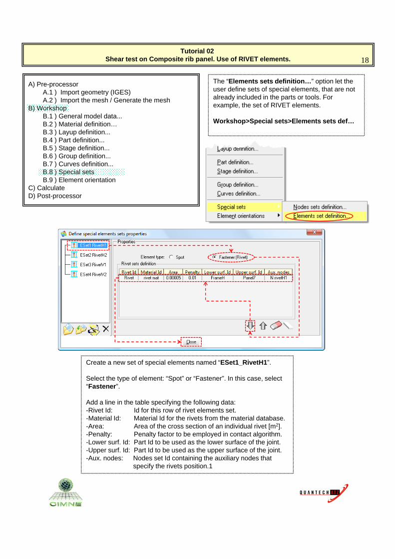
The “Elements sets definition…” option let the user define sets of special elements, that are not already included in the parts or tools. For example, the set of RIVET elements.B) Workshop
B.1 ) General model data...B.2 ) Material definition…B.3 ) Layup definition...B.4 ) Part definition...B.5 ) Stage definition... B.6 ) Group definition...B.7 ) Curves definition...B.8 ) Special sets
p
Workshop>Special sets>Elements sets def…
B.9 ) Element orientationC) CalculateD) Post-processor
Create a new set of special elements named “ESet1_RivetH1”.
Select the type of element: “Spot” or “Fastener”. In this case, select yp p“Fastener”.
Add a line in the table specifying the following data:-Rivet Id: Id for this row of rivet elements set.-Material Id: Material Id for the rivets from the material database.-Area: Area of the cross section of an individual rivet [m2].-Penalty: Penalty factor to be employed in contact algorithm.-Lower surf. Id: Part Id to be used as the lower surface of the joint.Upper surf Id: Part Id to be used as the upper surface of the joint-Upper surf. Id: Part Id to be used as the upper surface of the joint.
-Aux. nodes: Nodes set Id containing the auxiliary nodes that specify the rivets position.1
Tutorial 02 Shear test on Composite rib panel. Use of RIVET elements. 19
A) Pre-processorA.1 ) Import geometry (IGES)A.2 ) Import the mesh / Generate the mesh
B) Workshop
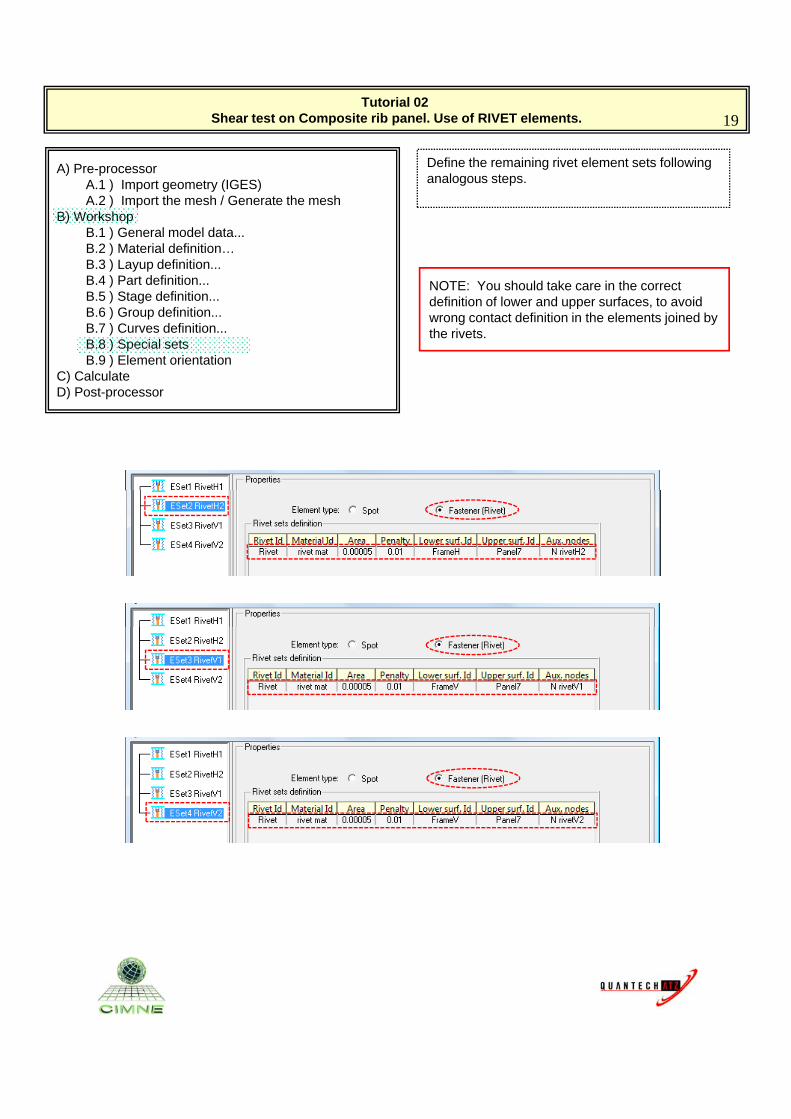
Define the remaining rivet element sets following analogous steps.
B) WorkshopB.1 ) General model data...B.2 ) Material definition…B.3 ) Layup definition...B.4 ) Part definition...B.5 ) Stage definition... B.6 ) Group definition...B.7 ) Curves definition...B.8 ) Special sets
NOTE: You should take care in the correct definition of lower and upper surfaces, to avoid wrong contact definition in the elements joined by the rivets.
B.9 ) Element orientationC) CalculateD) Post-processor
Tutorial 02 Shear test on Composite rib panel. Use of RIVET elements. 20
A) Pre-processorA.1 ) Import geometry (IGES)A.2 ) Import the mesh / Generate the mesh
B) Workshop
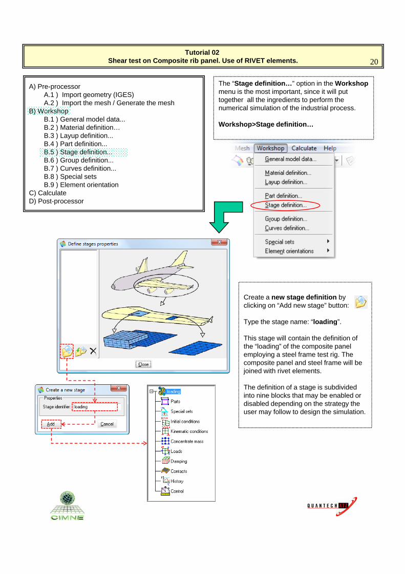
The “Stage definition…” option in the Workshopmenu is the most important, since it will put together all the ingredients to perform the numerical simulation of the industrial process.B) Workshop
B.1 ) General model data...B.2 ) Material definition…B.3 ) Layup definition...B.4 ) Part definition...B.5 ) Stage definition... B.6 ) Group definition...B.7 ) Curves definition...B.8 ) Special sets
p
Workshop>Stage definition…
B.9 ) Element orientationC) CalculateD) Post-processor
Create a new stage definition by clicking on “Add new stage” button:
Type the stage name: “loading”Type the stage name: loading .
This stage will contain the definition of the “loading” of the composite panel employing a steel frame test rig. The composite panel and steel frame will be joined with rivet elements.
The definition of a stage is subdivided into nine blocks that may be enabled or disabled depending on the strategy the user may follow to design the simulation.
Tutorial 02 Shear test on Composite rib panel. Use of RIVET elements. 21
A) Pre-processorA.1 ) Import geometry (IGES)A.2 ) Import the mesh / Generate the mesh
B) Workshop
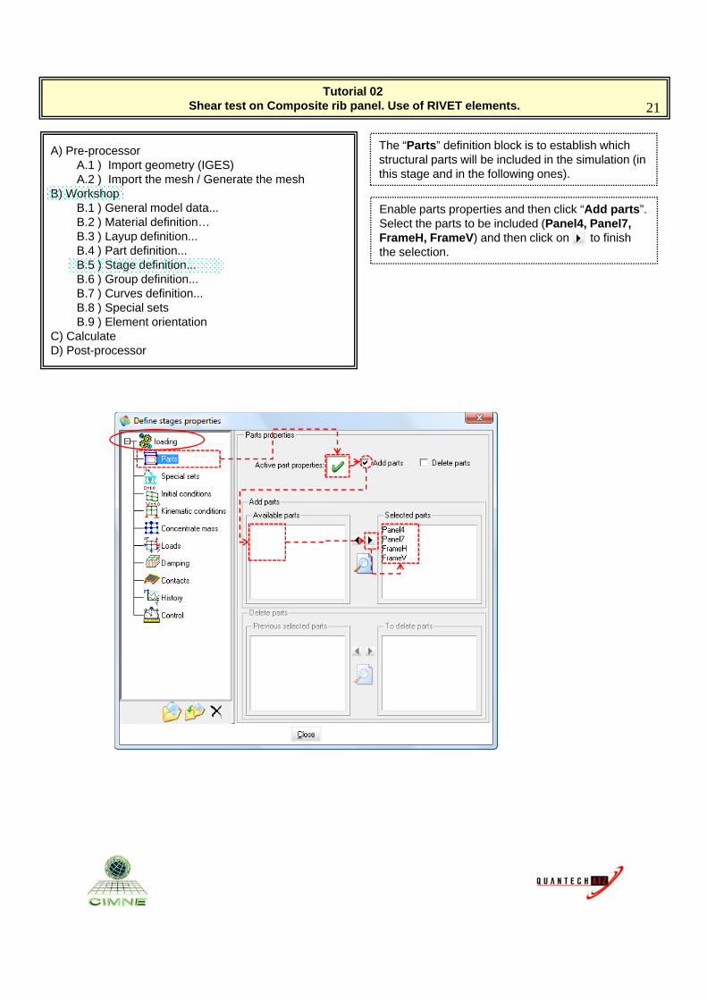
The “Parts” definition block is to establish which structural parts will be included in the simulation (in this stage and in the following ones).
B) WorkshopB.1 ) General model data...B.2 ) Material definition…B.3 ) Layup definition...B.4 ) Part definition...B.5 ) Stage definition... B.6 ) Group definition...B.7 ) Curves definition...B.8 ) Special sets
Enable parts properties and then click “Add parts”.Select the parts to be included (Panel4, Panel7, FrameH, FrameV) and then click on “” to finish the selection.
B.9 ) Element orientationC) CalculateD) Post-processor
Tutorial 02 Shear test on Composite rib panel. Use of RIVET elements. 22
A) Pre-processorA.1 ) Import geometry (IGES)A.2 ) Import the mesh / Generate the mesh
B) Workshop
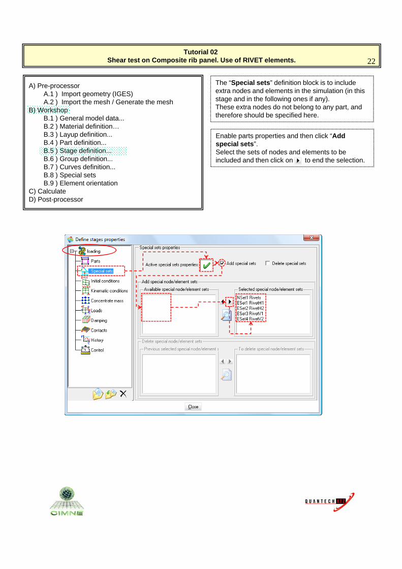
The “Special sets” definition block is to include extra nodes and elements in the simulation (in this stage and in the following ones if any).These extra nodes do not belong to any part, and B) Workshop
B.1 ) General model data...B.2 ) Material definition…B.3 ) Layup definition...B.4 ) Part definition...B.5 ) Stage definition... B.6 ) Group definition...B.7 ) Curves definition...B.8 ) Special sets
g y ptherefore should be specified here.
Enable parts properties and then click “Add special sets”.Select the sets of nodes and elements to be included and then click on “” to end the selection.
B.9 ) Element orientationC) CalculateD) Post-processor
Tutorial 02 Shear test on Composite rib panel. Use of RIVET elements. 23
A) Pre-processorA.1 ) Import geometry (IGES)A.2 ) Import the mesh / Generate the mesh
B) Workshop
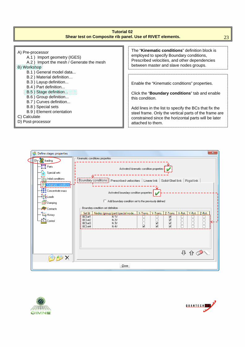
The “Kinematic conditions” definition block is employed to specify Boundary conditions, Prescribed velocities, and other dependencies between master and slave nodes groups.B) Workshop
B.1 ) General model data...B.2 ) Material definition…B.3 ) Layup definition...B.4 ) Part definition...B.5 ) Stage definition... B.6 ) Group definition...B.7 ) Curves definition...B.8 ) Special sets
g p
Enable the “Kinematic conditions” properties.
Click the “Boundary conditions” tab and enable this condition.
Add lines in the list to specify the BCs that fix the B.9 ) Element orientation
C) CalculateD) Post-processor
p ysteel frame. Only the vertical parts of the frame are constrained since the horizontal parts will be later attached to them.
Tutorial 02 Shear test on Composite rib panel. Use of RIVET elements. 24
A) Pre-processorA.1 ) Import geometry (IGES)A.2 ) Import the mesh / Generate the mesh
B) Workshop
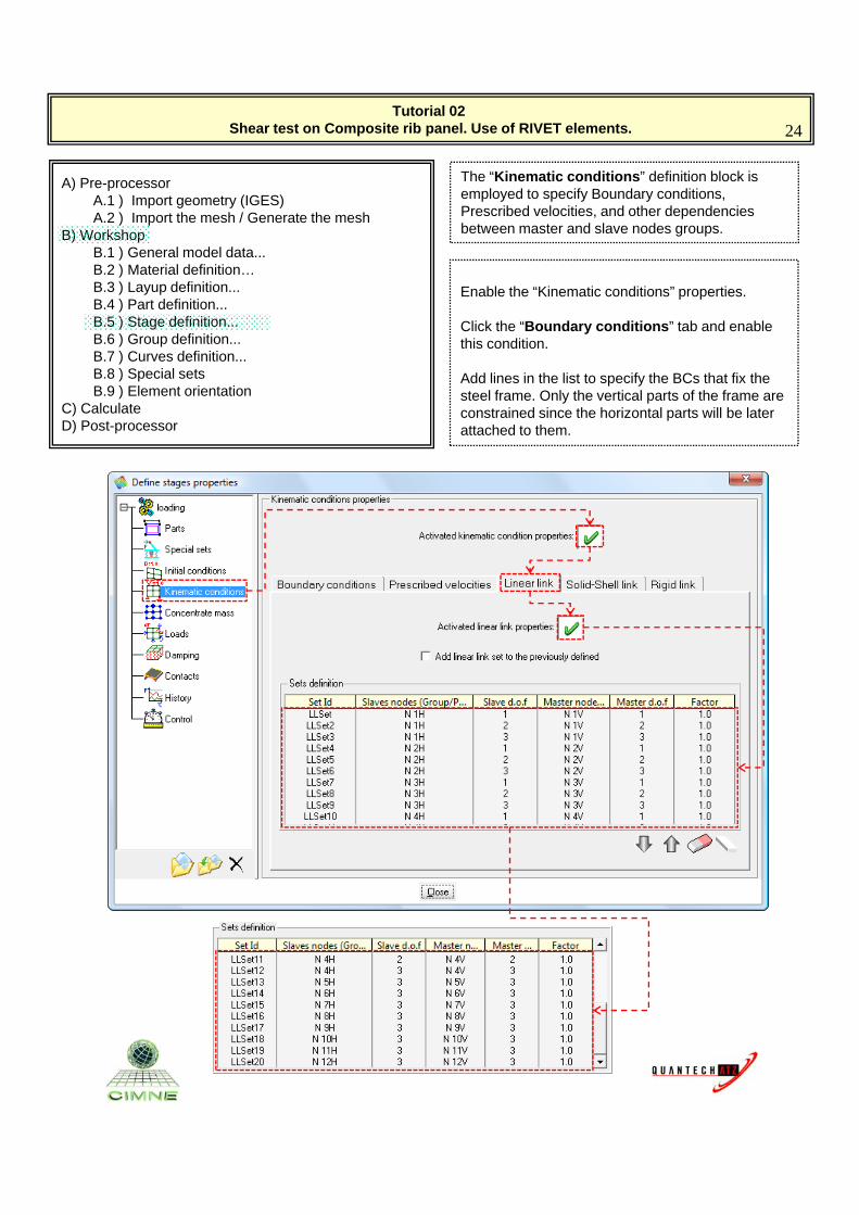
The “Kinematic conditions” definition block is employed to specify Boundary conditions, Prescribed velocities, and other dependencies between master and slave nodes groups.B) Workshop
B.1 ) General model data...B.2 ) Material definition…B.3 ) Layup definition...B.4 ) Part definition...B.5 ) Stage definition... B.6 ) Group definition...B.7 ) Curves definition...B.8 ) Special sets
g p
Enable the “Kinematic conditions” properties.
Click the “Boundary conditions” tab and enable this condition.
Add lines in the list to specify the BCs that fix the B.9 ) Element orientation
C) CalculateD) Post-processor
p ysteel frame. Only the vertical parts of the frame are constrained since the horizontal parts will be later attached to them.
Tutorial 02 Shear test on Composite rib panel. Use of RIVET elements. 25
A) Pre-processorA.1 ) Import geometry (IGES)A.2 ) Import the mesh / Generate the mesh
B) Workshop
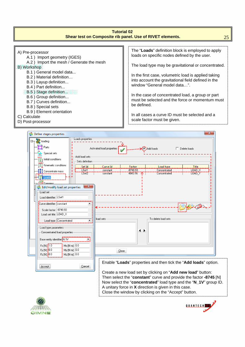
The “Loads” definition block is employed to apply loads on specific nodes defined by the user.
The load type may be gravitational or concentrated. B) WorkshopB.1 ) General model data...B.2 ) Material definition…B.3 ) Layup definition...B.4 ) Part definition...B.5 ) Stage definition... B.6 ) Group definition...B.7 ) Curves definition...B.8 ) Special sets
yp y g
In the first case, volumetric load is applied taking into account the gravitational field defined in the window “General model data…”.
In the case of concentrated load, a group or part must be selected and the force or momentum must be defined.
B.9 ) Element orientationC) CalculateD) Post-processor
In all cases a curve ID must be selected and a scale factor must be given.
Enable “Loads” properties and then tick the “Add loads” option.
Create a new load set by clicking on “Add new load” button: Then select the “constant” curve and provide the factor -8745 [N]p [ ]Now select the “concentrated” load type and the “N_1V” group ID.A unitary force in X direction is given in this case.Close the window by clicking on the “Accept” button.
Tutorial 02 Shear test on Composite rib panel. Use of RIVET elements. 26
A) Pre-processorA.1 ) Import geometry (IGES)A.2 ) Import the mesh / Generate the mesh
B) Workshop
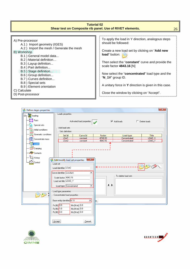
To apply the load in Y direction, analogous steps should be followed:
Create a new load set by clicking on “Add new B) WorkshopB.1 ) General model data...B.2 ) Material definition…B.3 ) Layup definition...B.4 ) Part definition...B.5 ) Stage definition... B.6 ) Group definition...B.7 ) Curves definition...B.8 ) Special sets
y gload” button:
Then select the “constant” curve and provide the scale factor 4843.16 [N]
Now select the “concentrated” load type and the “N_1V” group ID.
A unitary force in Y direction is given in this caseB.9 ) Element orientationC) CalculateD) Post-processor
A unitary force in Y direction is given in this case.
Close the window by clicking on “Accept”.
Tutorial 02 Shear test on Composite rib panel. Use of RIVET elements. 27
A) Pre-processorA.1 ) Import geometry (IGES)A.2 ) Import the mesh / Generate the mesh
B) Workshop
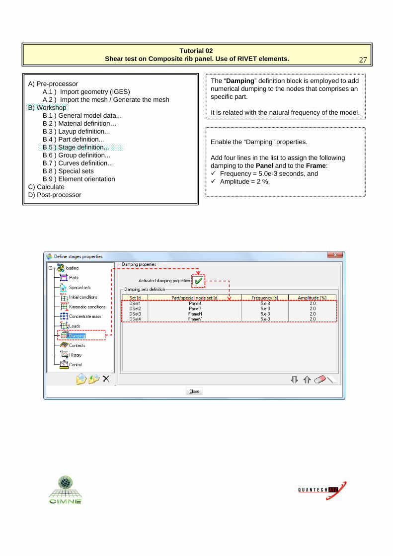
The “Damping” definition block is employed to add numerical dumping to the nodes that comprises an specific part.
B) WorkshopB.1 ) General model data...B.2 ) Material definition…B.3 ) Layup definition...B.4 ) Part definition...B.5 ) Stage definition... B.6 ) Group definition...B.7 ) Curves definition...B.8 ) Special sets
It is related with the natural frequency of the model.
Enable the “Damping” properties.
Add four lines in the list to assign the following damping to the Panel and to the Frame: Frequency = 5.0e-3 seconds, and
B.9 ) Element orientationC) CalculateD) Post-processor
Frequency 5.0e 3 seconds, and Amplitude = 2 %.
Tutorial 02 Shear test on Composite rib panel. Use of RIVET elements. 28
A) Pre-processorA.1 ) Import geometry (IGES)A.2 ) Import the mesh / Generate the mesh
B) Workshop
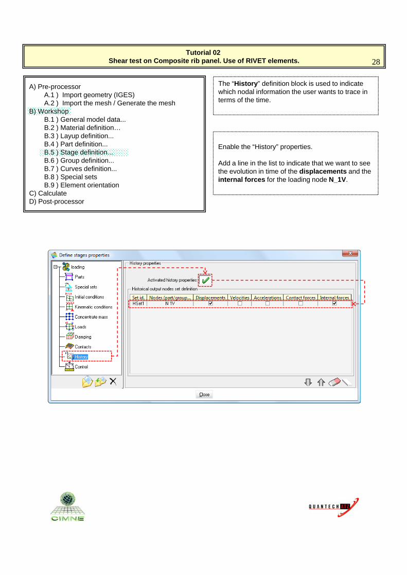
The “History” definition block is used to indicate which nodal information the user wants to trace in terms of the time.
B) WorkshopB.1 ) General model data...B.2 ) Material definition…B.3 ) Layup definition...B.4 ) Part definition...B.5 ) Stage definition... B.6 ) Group definition...B.7 ) Curves definition...B.8 ) Special sets
Enable the “History” properties.
Add a line in the list to indicate that we want to see the evolution in time of the displacements and the internal forces for the loading node N 1V.
B.9 ) Element orientationC) CalculateD) Post-processor
internal forces for the loading node N_1V.
Tutorial 02 Shear test on Composite rib panel. Use of RIVET elements. 29
A) Pre-processorA.1 ) Import geometry (IGES)A.2 ) Import the mesh / Generate the mesh
B) Workshop
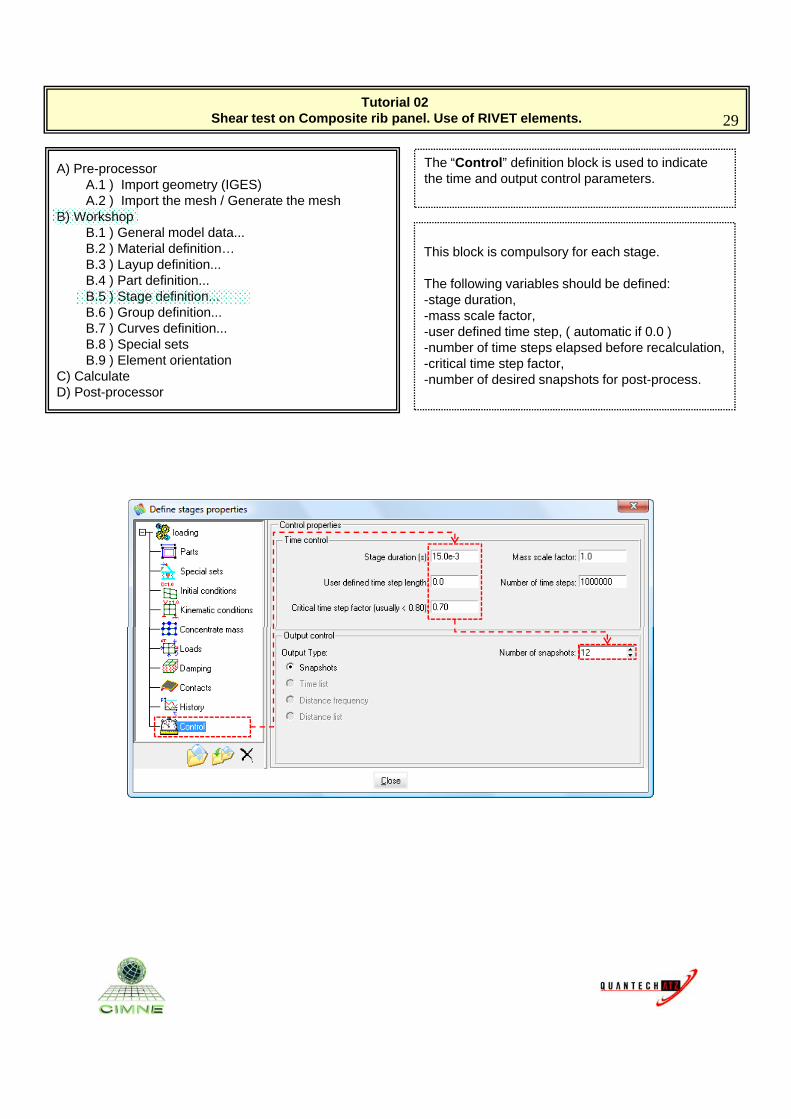
The “Control” definition block is used to indicate the time and output control parameters.
B) WorkshopB.1 ) General model data...B.2 ) Material definition…B.3 ) Layup definition...B.4 ) Part definition...B.5 ) Stage definition... B.6 ) Group definition...B.7 ) Curves definition...B.8 ) Special sets
This block is compulsory for each stage.
The following variables should be defined:-stage duration, -mass scale factor,-user defined time step, ( automatic if 0.0 )-number of time steps elapsed before recalculation,
B.9 ) Element orientationC) CalculateD) Post-processor
p p ,-critical time step factor,-number of desired snapshots for post-process.
Tutorial 02 Shear test on Composite rib panel. Use of RIVET elements. 30
A) Pre-processorA.1 ) Import geometry (IGES)A.2 ) Import the mesh / Generate the mesh
B) Workshop
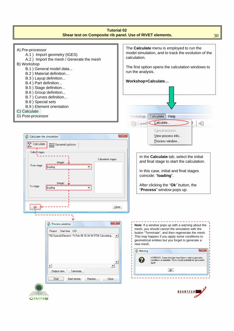
The Calculate menu is employed to run the model simulation, and to track the evolution of the calculation.
B) WorkshopB.1 ) General model data...B.2 ) Material definition…B.3 ) Layup definition...B.4 ) Part definition...B.5 ) Stage definition... B.6 ) Group definition...B.7 ) Curves definition...B.8 ) Special sets
The first option opens the calculation windows to run the analysis.
Workshop>Calculate…
B.9 ) Element orientationC) CalculateD) Post-processor
In the Calculate tab, select the initial and final stage to start the calculation.
In this case, initial and final stages coincide: “loading”.
After clicking the “Ok” button theAfter clicking the Ok button, the “Process” window pops up.
Note: If a window pops up with a warning about theNote: If a window pops up with a warning about the mesh, you should cancel the simulation with the button “Terminate”, and then regenerate the mesh.This may happen if you apply some conditions to geometrical entities but you forget to generate a new mesh.
Tutorial 02 Shear test on Composite rib panel. Use of RIVET elements. 31
A) Pre-processorA.1 ) Import geometry (IGES)A.2 ) Import the mesh / Generate the mesh
B) Workshop
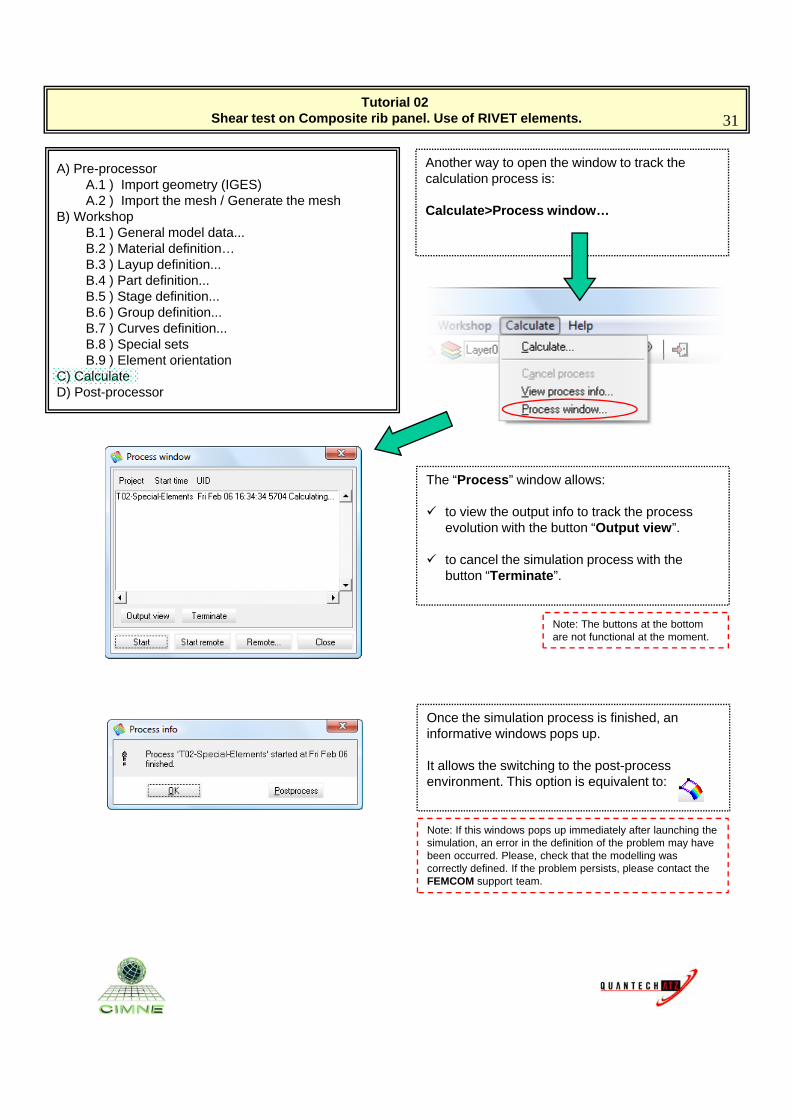
Another way to open the window to track the calculation process is:
Calculate>Process window…B) WorkshopB.1 ) General model data...B.2 ) Material definition…B.3 ) Layup definition...B.4 ) Part definition...B.5 ) Stage definition... B.6 ) Group definition...B.7 ) Curves definition...B.8 ) Special setsB.9 ) Element orientation
C) CalculateD) Post-processor
The “Process” window allows:
to view the output info to track the process evolution with the button “Output view”.
to cancel the simulation process with the button “Terminate”.
Note: The buttons at the bottomNote: The buttons at the bottom are not functional at the moment.
Once the simulation process is finished, an informative windows pops up.
It allows the switching to the post processIt allows the switching to the post-process environment. This option is equivalent to:
Note: If this windows pops up immediately after launching the simulation, an error in the definition of the problem may have been occurred. Please, check that the modelling was correctly defined. If the problem persists, please contact the FEMCOM support team.
Tutorial 02 Shear test on Composite rib panel. Use of RIVET elements. 32
A) Pre-processorA.1 ) Import geometry (IGES)A.2 ) Import the mesh / Generate the mesh
B) Workshop
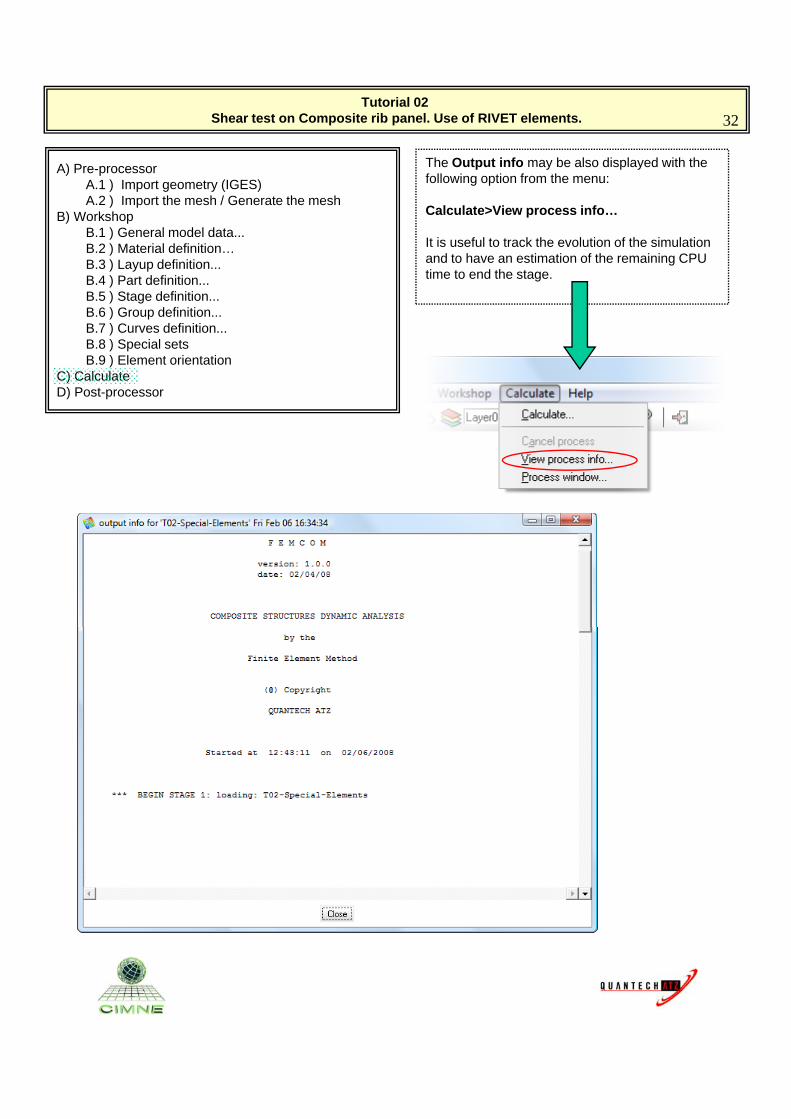
The Output info may be also displayed with the following option from the menu:
Calculate>View process info…B) WorkshopB.1 ) General model data...B.2 ) Material definition…B.3 ) Layup definition...B.4 ) Part definition...B.5 ) Stage definition... B.6 ) Group definition...B.7 ) Curves definition...B.8 ) Special sets
p
It is useful to track the evolution of the simulation and to have an estimation of the remaining CPU time to end the stage.
B.9 ) Element orientationC) CalculateD) Post-processor
Tutorial 02 Shear test on Composite rib panel. Use of RIVET elements. 33
A) Pre-processorA.1 ) Import geometry (IGES)A.2 ) Import the mesh / Generate the mesh
B) Workshop
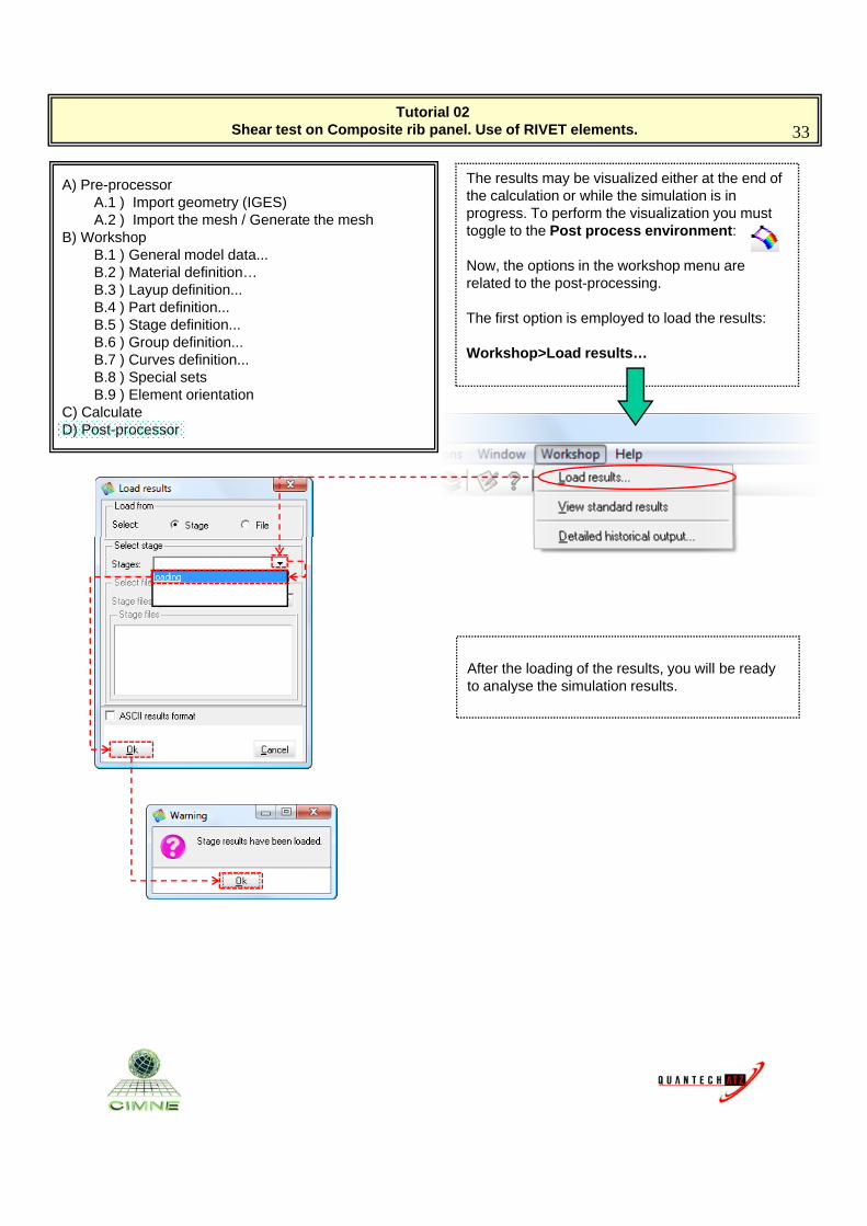
The results may be visualized either at the end of the calculation or while the simulation is in progress. To perform the visualization you must toggle to the Post process environment: B) Workshop
B.1 ) General model data...B.2 ) Material definition…B.3 ) Layup definition...B.4 ) Part definition...B.5 ) Stage definition... B.6 ) Group definition...B.7 ) Curves definition...B.8 ) Special sets
gg p
Now, the options in the workshop menu are related to the post-processing.
The first option is employed to load the results:
Workshop>Load results…
B.9 ) Element orientationC) CalculateD) Post-processor
After the loading of the results, you will be ready to analyse the simulation resultsto analyse the simulation results.
Tutorial 02 Shear test on Composite rib panel. Use of RIVET elements. 34
A) Pre-processorA.1 ) Import geometry (IGES)A.2 ) Import the mesh / Generate the mesh
B) Workshop
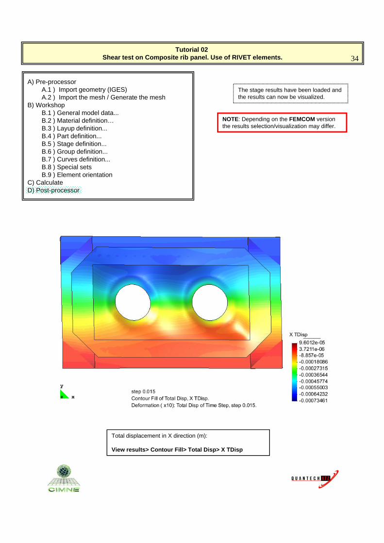
The stage results have been loaded and the results can now be visualized.
B) WorkshopB.1 ) General model data...B.2 ) Material definition…B.3 ) Layup definition...B.4 ) Part definition...B.5 ) Stage definition... B.6 ) Group definition...B.7 ) Curves definition...B.8 ) Special sets
NOTE: Depending on the FEMCOM version the results selection/visualization may differ.
B.9 ) Element orientationC) CalculateD) Post-processor
Total displacement in X direction (m):Total displacement in X direction (m):
View results> Contour Fill> Total Disp> X TDisp