Embed Size (px)
Citation preview

User’sManual
Yokogawa Electric Corporation
AXFA11GMagnetic FlowmeterRemote Converter[Hardware Edition/Software Edition]
IM 01E20C01-01E
IM 01E20C01-01E9th Edition
i
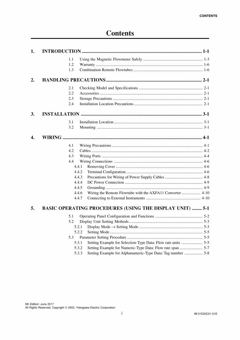
CONTENTS
IM 01E20C01-01E
9th Edition: June 2017All Rights Reserved, Copyright © 2003, Yokogawa Electric Corporation
Contents
1. INTRODUCTION ................................................................................................... 1-1
1.1 Using the Magnetic Flowmeter Safely ........................................................... 1-31.2 Warranty .......................................................................................................... 1-61.3 Combination Remote Flowtubes ..................................................................... 1-6
2. HANDLING PRECAUTIONS ............................................................................... 2-1
2.1 Checking Model and Specifications ............................................................... 2-12.2 Accessories ...................................................................................................... 2-12.3 Storage Precautions ......................................................................................... 2-12.4 Installation Location Precautions .................................................................... 2-1
3. INSTALLATION .................................................................................................... 3-1
3.1 Installation Location ........................................................................................ 3-13.2 Mounting ......................................................................................................... 3-1
4. WIRING ................................................................................................................... 4-1
4.1 Wiring Precautions .......................................................................................... 4-14.2 Cables .............................................................................................................. 4-24.3 Wiring Ports .................................................................................................... 4-44.4 Wiring Connections ........................................................................................ 4-6
4.4.1 Removing Cover ...................................................................................... 4-64.4.2 Terminal Configuration ............................................................................ 4-64.4.3 Precautions for Wiring of Power Supply Cables ..................................... 4-84.4.4 DC Power Connection ............................................................................. 4-94.4.5 Grounding ................................................................................................ 4-94.4.6 Wiring the Remote Flowtube with the AXFA11 Converter ................... 4-104.4.7 Connecting to External Instruments ...................................................... 4-10
5. BASIC OPERATING PROCEDURES (USING THE DISPLAY UNIT) ........ 5-1
5.1 Operating Panel Configuration and Functions ............................................... 5-25.2 Display Unit Setting Methods ......................................................................... 5-3
5.2.1 Display Mode → Setting Mode ............................................................... 5-35.2.2 Setting Mode ............................................................................................ 5-5
5.3 Parameter Setting Procedure ........................................................................... 5-55.3.1 Setting Example for Selection-Type Data: Flow rate units ..................... 5-55.3.2 Setting Example for Numeric-Type Data: Flow rate span ....................... 5-75.3.3 Setting Example for Alphanumeric-Type Data: Tag number .................. 5-8
ii
CONTENTS
IM 01E20C01-01E
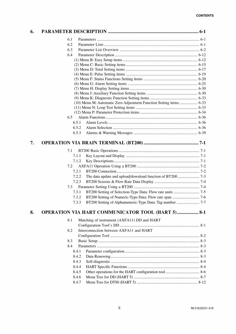
6. PARAMETER DESCRIPTION ............................................................................ 6-1
6.1 Parameters ....................................................................................................... 6-16.2 Parameter Lists ................................................................................................ 6-16.3 Parameter List Overview ................................................................................ 6-26.4 Parameter Description ................................................................................... 6-12
(1) Menu B: Easy Setup items ........................................................................... 6-12(2) Menu C: Basic Setting items ........................................................................ 6-15(3) Menu D: Total Setting items ........................................................................ 6-17(4) Menu E: Pulse Setting items ........................................................................ 6-19(5) Menu F: Status Functions Setting items ...................................................... 6-20(6) Menu G: Alarm Setting items ...................................................................... 6-25(7) Menu H: Display Setting items .................................................................... 6-30(8) Menu J: Auxiliary Function Setting items ................................................... 6-30(9) Menu K: Diagnostic Function Setting items ................................................ 6-33(10) Menu M: Automatic Zero Adjustment Function Setting items .................. 6-33(11) Menu N: Loop Test Setting items .............................................................. 6-33(12) Menu P: Parameter Protection items .......................................................... 6-34
6.5 Alarm Functions ............................................................................................ 6-366.5.1 Alarm Levels .......................................................................................... 6-366.5.2 Alarm Selection ..................................................................................... 6-366.5.3 Alarms & Warning Messages ................................................................ 6-39
7. OPERATION VIA BRAIN TERMINAL (BT200) .............................................. 7-1
7.1 BT200 Basic Operations ................................................................................. 7-17.1.1 Key Layout and Display .......................................................................... 7-17.1.2 Key Descriptions ...................................................................................... 7-1
7.2 AXFA11 Operation Using a BT200 ............................................................... 7-27.2.1 BT200 Connection ................................................................................... 7-27.2.2 The data update and upload/download function of BT200...................... 7-37.2.3 BT200 Screens & Flow Rate Data Display ............................................. 7-4
7.3 Parameter Setting Using a BT200 .................................................................. 7-47.3.1 BT200 Setting of Selection-Type Data: Flow rate units .......................... 7-57.3.2 BT200 Setting of Numeric-Type Data: Flow rate span ........................... 7-67.3.3 BT200 Setting of Alphanumeric-Type Data: Tag number ....................... 7-7
8. OPERATION VIA HART COMMUNICATOR TOOL (HART 5) .................. 8-1
8.1 Matching of instrument (AXFA11) DD and HARTConfiguration Tool’s DD ................................................................................ 8-1
8.2 Interconnection between AXFA11 and HARTConfiguration Tool .......................................................................................... 8-2
8.3 Basic Setup ...................................................................................................... 8-38.4 Parameters ....................................................................................................... 8-3
8.4.1 Parameter configuration ........................................................................... 8-38.4.2 Data Renewing ......................................................................................... 8-38.4.3 Self-diagnostic ......................................................................................... 8-48.4.4 HART Specific Functions ........................................................................ 8-48.4.5 Other operations for the HART configuration tool .................................. 8-68.4.6 Menu Tree for DD (HART 5) .................................................................. 8-78.4.7 Menu Tree for DTM (HART 5) ............................................................. 8-12
iii
CONTENTS
IM 01E20C01-01E
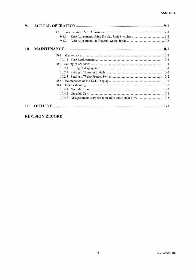
9. ACTUAL OPERATION ......................................................................................... 9-1
9.1 Pre-operation Zero Adjustment ....................................................................... 9-19.1.1 Zero Adjustment Using Display Unit Switches ....................................... 9-29.1.2 Zero Adjustment via External Status Input .............................................. 9-3
10. MAINTENANCE .................................................................................................. 10-1
10.1 Maintenance .................................................................................................. 10-110.1.1 Fuse Replacement .................................................................................. 10-1
10.2 Setting of Switches ....................................................................................... 10-110.2.1 Lifting of display unit ............................................................................ 10-110.2.2 Setting of Burnout Switch ..................................................................... 10-210.2.3 Setting of Write Protect Switch ............................................................. 10-2
10.3 Maintenance of the LCD Display ................................................................. 10-210.4 Troubleshooting ............................................................................................. 10-3
10.4.1 No Indication ......................................................................................... 10-310.4.2 Unstable Zero ......................................................................................... 10-410.4.3 Disagreement Between Indication and Actual Flow.............................. 10-5
11. OUTLINE............................................................................................................... 11-1
REVISION RECORD
IM 01E20C01-01E1-1
1. INTRODUCTION
1. INTRODUCTION
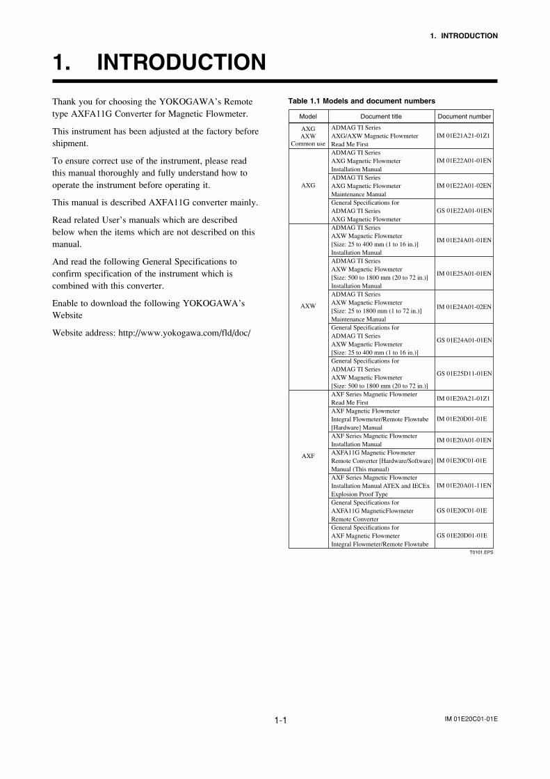
Thank you for choosing the YOKOGAWA’s Remotetype AXFA11G Converter for Magnetic Flowmeter.
This instrument has been adjusted at the factory beforeshipment.
To ensure correct use of the instrument, please readthis manual thoroughly and fully understand how tooperate the instrument before operating it.
This manual is described AXFA11G converter mainly.
Read related User’s manuals which are describedbelow when the items which are not described on thismanual.
And read the following General Specifications toconfirm specification of the instrument which iscombined with this converter.
Enable to download the following YOKOGAWA’sWebsite
Website address: http://www.yokogawa.com/fld/doc/
Table 1.1 Models and document numbers
T0101.EPS
IM 01E21A21-01Z1
IM 01E22A01-01EN
IM 01E22A01-02EN
GS 01E22A01-01EN
IM 01E24A01-01EN
IM 01E25A01-01EN
IM 01E24A01-02EN
GS 01E24A01-01EN
GS 01E25D11-01EN
IM 01E20A21-01Z1
IM 01E20D01-01E
IM 01E20A01-01EN
IM 01E20C01-01E
IM 01E20A01-11EN
GS 01E20C01-01E
GS 01E20D01-01E
ADMAG TI SeriesAXG/AXW Magnetic FlowmeterRead Me FirstADMAG TI Series AXG Magnetic Flowmeter Installation ManualADMAG TI Series AXG Magnetic Flowmeter Maintenance ManualGeneral Specifications for ADMAG TI Series AXG Magnetic FlowmeterADMAG TI Series AXW Magnetic Flowmeter [Size: 25 to 400 mm (1 to 16 in.)] Installation ManualADMAG TI Series AXW Magnetic Flowmeter [Size: 500 to 1800 mm (20 to 72 in.)] Installation ManualADMAG TI Series AXW Magnetic Flowmeter [Size: 25 to 1800 mm (1 to 72 in.)] Maintenance ManualGeneral Specifications for ADMAG TI Series AXW Magnetic Flowmeter [Size: 25 to 400 mm (1 to 16 in.)]General Specifications for ADMAG TI Series AXW Magnetic Flowmeter [Size: 500 to 1800 mm (20 to 72 in.)]AXF Series Magnetic Flowmeter Read Me FirstAXF Magnetic Flowmeter Integral Flowmeter/Remote Flowtube [Hardware] ManualAXF Series Magnetic Flowmeter Installation ManualAXFA11G Magnetic Flowmeter Remote Converter [Hardware/Software] Manual (This manual)AXF Series Magnetic Flowmeter Installation Manual ATEX and IECEx Explosion Proof TypeGeneral Specifications for AXFA11G MagneticFlowmeter Remote ConverterGeneral Specifications for AXF Magnetic Flowmeter Integral Flowmeter/Remote Flowtube
AXGAXW
Common use
AXW
AXG
AXF
Document titleModel Document number
IM 01E20C01-01E1-2
1. INTRODUCTION
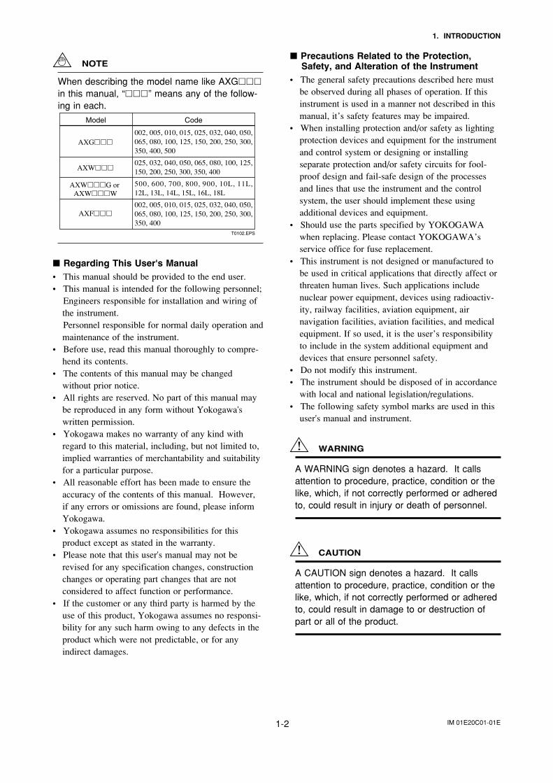
NOTE
When describing the model name like AXG
in this manual, “” means any of the follow-ing in each.
Model Code
AXG
AXW
AXWG or AXWW
AXF
T0102.EPS
002, 005, 010, 015, 025, 032, 040, 050, 065, 080, 100, 125, 150, 200, 250, 300, 350, 400, 500
025, 032, 040, 050, 065, 080, 100, 125, 150, 200, 250, 300, 350, 400
500, 600, 700, 800, 900, 10L, 11L, 12L, 13L, 14L, 15L, 16L, 18L
002, 005, 010, 015, 025, 032, 040, 050, 065, 080, 100, 125, 150, 200, 250, 300, 350, 400
Regarding This User's Manual• This manual should be provided to the end user.• This manual is intended for the following personnel;
Engineers responsible for installation and wiring ofthe instrument.Personnel responsible for normal daily operation andmaintenance of the instrument.
• Before use, read this manual thoroughly to compre-hend its contents.
• The contents of this manual may be changedwithout prior notice.
• All rights are reserved. No part of this manual maybe reproduced in any form without Yokogawa'swritten permission.
• Yokogawa makes no warranty of any kind withregard to this material, including, but not limited to,implied warranties of merchantability and suitabilityfor a particular purpose.
• All reasonable effort has been made to ensure theaccuracy of the contents of this manual. However,if any errors or omissions are found, please informYokogawa.
• Yokogawa assumes no responsibilities for thisproduct except as stated in the warranty.
• Please note that this user's manual may not berevised for any specification changes, constructionchanges or operating part changes that are notconsidered to affect function or performance.
• If the customer or any third party is harmed by theuse of this product, Yokogawa assumes no responsi-bility for any such harm owing to any defects in theproduct which were not predictable, or for anyindirect damages.
Precautions Related to the Protection,Safety, and Alteration of the Instrument
• The general safety precautions described here mustbe observed during all phases of operation. If thisinstrument is used in a manner not described in thismanual, it’s safety features may be impaired.
• When installing protection and/or safety as lightingprotection devices and equipment for the instrumentand control system or designing or installingseparate protection and/or safety circuits for fool-proof design and fail-safe design of the processesand lines that use the instrument and the controlsystem, the user should implement these usingadditional devices and equipment.
• Should use the parts specified by YOKOGAWAwhen replacing. Please contact YOKOGAWA’sservice office for fuse replacement.
• This instrument is not designed or manufactured tobe used in critical applications that directly affect orthreaten human lives. Such applications includenuclear power equipment, devices using radioactiv-ity, railway facilities, aviation equipment, airnavigation facilities, aviation facilities, and medicalequipment. If so used, it is the user’s responsibilityto include in the system additional equipment anddevices that ensure personnel safety.
• Do not modify this instrument.• The instrument should be disposed of in accordance
with local and national legislation/regulations.• The following safety symbol marks are used in this
user's manual and instrument.
WARNING
A WARNING sign denotes a hazard. It callsattention to procedure, practice, condition or thelike, which, if not correctly performed or adheredto, could result in injury or death of personnel.
CAUTION
A CAUTION sign denotes a hazard. It callsattention to procedure, practice, condition or thelike, which, if not correctly performed or adheredto, could result in damage to or destruction ofpart or all of the product.
IM 01E20C01-01E1-3
1. INTRODUCTION
IMPORTANT
An IMPORTANT sign denotes that attention isrequired to avoid damage to the instrument orsystem failure.
NOTE
A NOTE sign denotes information necessary foressential understanding of operation and fea-tures.
Protective grounding terminal
Functional grounding terminal(This terminal should not be used as a protectivegrounding terminal.)
Alternating current
Direct current
1.1 Using the MagneticFlowmeter Safely
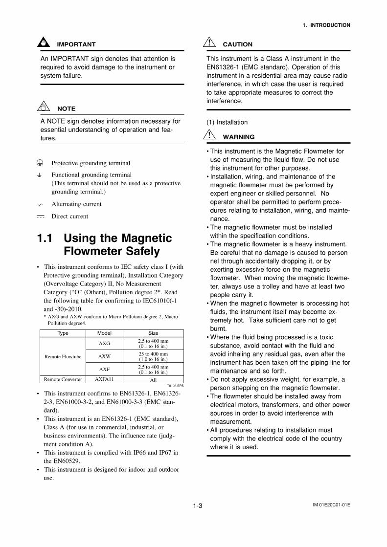
• This instrument conforms to IEC safety class I (withProtective grounding terminal), Installation Category(Overvoltage Category) II, No MeasurementCategory (“O” (Other)), Pollution degree 2*. Readthe following table for confirming to IEC61010(-1and -30)-2010.* AXG and AXW conform to Micro Pollution degree 2, Macro
Pollution degree4.
T0103.EPS
ModelType Size
AXG
AXW
AXF
AXFA11
2.5 to 400 mm(0.1 to 16 in.)
25 to 400 mm(1.0 to 16 in.)
2.5 to 400 mm(0.1 to 16 in.)
All
Remote Flowtube
Remote Converter
• This instrument confirms to EN61326-1, EN61326-2-3, EN61000-3-2, and EN61000-3-3 (EMC stan-dard).
• This instrument is an EN61326-1 (EMC standard),Class A (for use in commercial, industrial, orbusiness environments). The influence rate (judg-ment condition A).
• This instrument is complied with IP66 and IP67 inthe EN60529.
• This instrument is designed for indoor and outdooruse.
CAUTION
This instrument is a Class A instrument in theEN61326-1 (EMC standard). Operation of thisinstrument in a residential area may cause radiointerference, in which case the user is requiredto take appropriate measures to correct theinterference.
(1) Installation
WARNING
• This instrument is the Magnetic Flowmeter foruse of measuring the liquid flow. Do not usethis instrument for other purposes.
• Installation, wiring, and maintenance of themagnetic flowmeter must be performed byexpert engineer or skilled personnel. Nooperator shall be permitted to perform proce-dures relating to installation, wiring, and mainte-nance.
• The magnetic flowmeter must be installedwithin the specification conditions.
• The magnetic flowmeter is a heavy instrument.Be careful that no damage is caused to person-nel through accidentally dropping it, or byexerting excessive force on the magneticflowmeter. When moving the magnetic flowme-ter, always use a trolley and have at least twopeople carry it.
• When the magnetic flowmeter is processing hotfluids, the instrument itself may become ex-tremely hot. Take sufficient care not to getburnt.
• Where the fluid being processed is a toxicsubstance, avoid contact with the fluid andavoid inhaling any residual gas, even after theinstrument has been taken off the piping line formaintenance and so forth.
• Do not apply excessive weight, for example, aperson sttepping on the magnetic flowmeter.
• The flowmeter should be installed away fromelectrical motors, transformers, and other powersources in order to avoid interference withmeasurement.
• All procedures relating to installation mustcomply with the electrical code of the countrywhere it is used.
IM 01E20C01-01E1-4
1. INTRODUCTION
(2) Wiring
WARNING
• The wiring of the magnetic flowmeter must beperformed by expert engineer or skilled person-nel. No operator shall be permitted to performprocedures relating to wiring.
• In cases where the ambient temperatureexceeds 50°C, use external heat resistantwiring with a maximum allowable temperatureof 70°C or above.
• Ensure that the source voltage matches thevoltage of the power supply before turning ONthe power.
Power supply code 1;• AC specification: Rated power supply
100 to 240 Vac, 50/60 Hz• DC specification: Rated power supply
100 to 120 VdcPower supply code 2;
• AC specification: Rated power supply24 Vac, 50/60 Hz
• DC specification: Rated power supply24 Vdc
Power consumption:20 W (Combination of AXFA11 RemoteConverter and AXG, AXW and AXFRemote Flowtube each.)Note: The power consumption is the same as above
regardless of the communication type.
• Ensure to connect the protective grounding toprevent electric shock before turning ON thepower.
• Never cut off the internal or external protectivegrounding wire or disconnect the wiring of theprotective grounding terminal. Doing so invali-dates the protective functions of the instrumentand poses a potential shock hazard.
• Do not operate the instrument if the protectivegrounding might be defective. Also, ensure tocheck them before operation.
• Connect the protective grounding beforeconnecting to the item under measurement orcontrol unit.
• Operating the instrument in a manner neitherdescribed in this manual nor the related manu-als (see Table 1.1) may damage theinstrument’s protection.
• When wiring the conduits, pass the conduitthrough the wiring connection port, and utilizethe waterproof gland to prevent water fromflowing in. Install a drain valve at the low end ofthe vertical pipe, and open the valve regularly.
• Do not open the cover in wet weather or humidenvironment. When the cover is open, statedenclosure protection is not applicable.
• Do not connect cables outdoors in wet weatherin order to prevent condensation and to protectthe insulation, e.g. inside the terminal box ofthe flowmeter.
• Install an external switch or circuit breaker as ameans to turn the power OFF (capacitance;15A, conforming to IEC60947-1 and IEC60947-3).
• This instrument employs the parts which areaffected by a function damage caused by staticelectricity. Thus, you should do the antistaticwork using an anti-static wrist band and becareful to avoid touching each electrical partsand circuitry directly.
• When connecting the wiring, check that thesupply voltage is within the range of the voltagespecified for this instrument before connectingthe power cable. In addition, check that novoltage is applied to the power cable beforeconnecting the wiring.
• To prevent electric shocks, do not impress overrated voltage to each input/output terminals.
• The cover should be removed byYOKOGAWA’s qualified personnel only. Open-ing the cover is dangerous, because someareas inside the instrument have high voltages.
(3) Operation
WARNING
• Do not operate the instrument in the presenceof flammable gas, vapors, or combustible dust.Operation in such an environment constitutes asafety hazard. Prolonged use in a highly densecorrosive gas (H2S, SOx, etc.) will cause amalfunction.
• The cover should be removed byYOKOGAWA’s qualified personnel only. Open-ing the cover is dangerous, because someareas inside the instrument have high voltages.
• When opening the cover, wait for more than 10minutes after turning off the power. Onlyexpert engineer or skilled personnel are permit-ted to open the cover.
• Do not open the cover in wet weather or humidenvironment. When the cover is open, statedenclosure protection is not applicable.
• Be sure to set parameters as "Protect" on thewrite protect function after finish of parametersetting work.
IM 01E20C01-01E1-5
1. INTRODUCTION
Under extremely rare case, the infra-redswitches may respond unexpectedly in suchconditions as sticking ball of water orextraneous substances on the surface ofdisplay panel glass according to the principle ofinfra-red switch operation.Its probability rises in such cases as stickingrain water by storm or other similar situationand washing up work near flowmeter installa-tion place.Either to illuminate or stop illuminating the infra-red switches by the flashlight may cause themis-reaction.Refer to Chapter 6 "Menu P: Parameter Protec-tion Items" and section "10.2.3" how to use thewrite protect function in detail.
(4) Maintenance
WARNING
• Maintenance of the magnetic flowmeter shouldbe performed by the trained personnel havingknowledge of safety standard. No operatorshall be permitted to perform any operationsrelating to maintenance.
• As a rule, maintenance of this flowmeter shouldbe implemented in a maintenance service shopwhere the necessity tools are provided.
• When opening the cover, wait for more than 10minutes after turning off the power.
• Do not open the cover in wet weather or humidenvironment. When the cover is open, statedenclosure protection is not applicable.
• The cover should be removed byYOKOGAWA’s qualified personnel only. Open-ing the cover is dangerous, because someareas inside the instrument have high voltages.
• Always conform to maintenance proceduresoutlined in this manual. If necessary, contactYokogawa.
• Care should be taken to prevent the build up ofdirt, dust or other substances on the displaypanel glass or name plate. If these surfaces doget dirty, wipe them clean with a soft dry cloth.
(5) Modification
WARNING
• Yokogawa will not be liable for malfunctions ordamage resulting from any modification madeto this instrument by the customer.
(6) Product DisposalThe instrument should be disposed of in accordancewith local and national legislation/regulations.
(7) Authorized Representative in EEAIn relation to the CE Marking, The authorizedrepresentative for this product in the EEA (EuropeanEconomic Area) is:Yokogawa Europe B.V.Euroweg 2, 3825 HD Amersfoort, The Netherlands
IM 01E20C01-01E1-6
1. INTRODUCTION
1.2 Warranty• The terms of this instrument that are guaranteed are
described in the quotation. We will make any repairsthat may become necessary during the guaranteedterm free of charge.
• Please contact our sales office if this instrumentrequires repair.
• If the instrument is faulty, contact us with concretedetails about the problem and the length of time ithas been faulty, and state the model and serialnumber. We would appreciate the inclusion ofdrawings or additional information.
• The results of our examination will determinewhether the meter will be repaired free of charge oron an at-cost basis.
The guarantee will not apply in the followingcases:
• Damage due to negligence or insufficient mainte-nance on the part of the customer.
• Problems or damage resulting from handling,operation or storage that violates the intended useand specifications.
• Problems that result from using or performingmaintenance on the instrument in a location thatdoes not comply with the installation locationspecified by Yokogawa.
• Problems or damage resulting from repairs ormodifications not performed by Yokogawa orsomeone authorized by Yokogawa.
• Problems or damage resulting from inappropriatereinstallation after delivery.
• Problems or damage resulting from disasters such asfires, earthquakes, storms, floods, or lightning strikesand external causes.
Trademarks:• All the brands or names of Yokogawa Electric’s
products used in this manual are either trademarks orregistered trademarks of Yokogawa Electric Corpo-ration.
• All other company and product names mentioned inthis manual are trade names, trademarks or regis-tered trademarks of their respective companies.
• In this manual, trademarks or registered trademarksare not marked with ™ or ®.
1.3 Combination RemoteFlowtubes
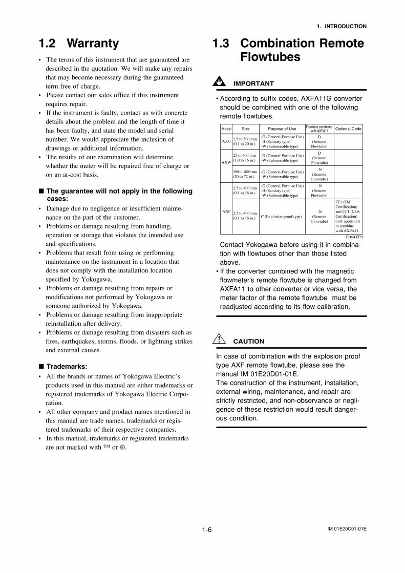
IMPORTANT
• According to suffix codes, AXFA11G convertershould be combined with one of the followingremote flowtubes.
Model Size Purpose of Use Flowtube combined with AXFA11 Optional Code
T0104.EPS
2.5 to 500 mm(0.1 to 20 in.)
25 to 400 mm(1.0 to 16 in.)
500 to 1800 mm(20 to 72 in.)
2.5 to 400 mm(0.1 to 16 in.)
2.5 to 400 mm(0.1 to 16 in.)
AXG
AXW
AXF
-G (General-Purpose Use)-H (Sanitary type)-W (Submersible type)
-G (General-Purpose Use)-W (Submersible type)
-G (General-Purpose Use)-W (Submersible type)
-G (General-Purpose Use)-H (Sanitary type)-W (Submersible type)
C (Explosion proof type)
D(Remote
Flowtube)
D(Remote Flowtube)
-N(Remote Flowtube)
-N(Remote
Flowtube)
-N(Remote Flowtube)
FF1 (FM Certification) and CF1 (CSA Certification) only applicable to combine with AXFA11.
Contact Yokogawa before using it in combina-tion with flowtubes other than those listedabove.
• If the converter combined with the magneticflowmeter's remote flowtube is changed fromAXFA11 to other converter or vice versa, themeter factor of the remote flowtube must bereadjusted according to its flow calibration.
CAUTION
In case of combination with the explosion prooftype AXF remote flowtube, please see themanual IM 01E20D01-01E.The construction of the instrument, installation,external wiring, maintenance, and repair arestrictly restricted, and non-observance or negli-gence of these restriction would result danger-ous condition.
IM 01E20C01-01E2-1
2. HANDLING PRECAUTIONS
2. HANDLING PRECAUTIONS
This instrument has been inspected carefully at thefactory before shipment. When the instrument isdelivered, visually check that no damage has occurredduring transportation.
Read this section carefully as it contains importantinformation on handling this instrument. Refer to therelevant sections for information not contained in thissection. If you have any problems or questions, pleasecontact Yokogawa sales office.
2.1 Checking Model andSpecifications
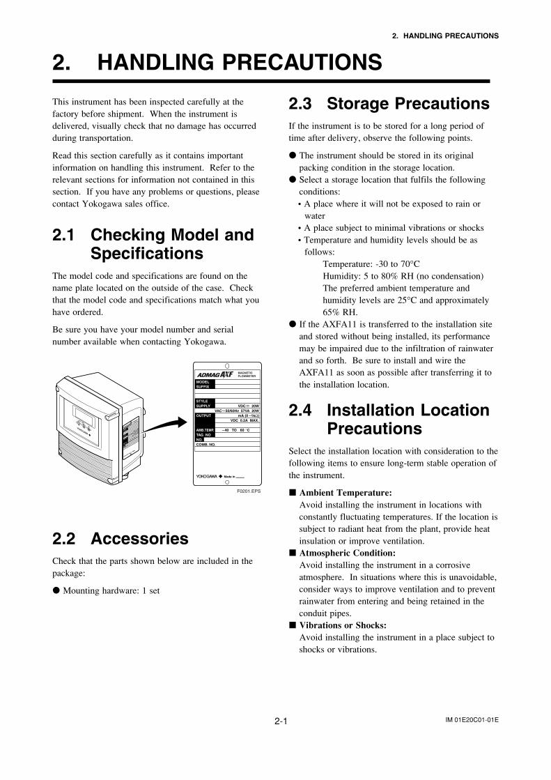
The model code and specifications are found on thename plate located on the outside of the case. Checkthat the model code and specifications match what youhave ordered.
Be sure you have your model number and serialnumber available when contacting Yokogawa.
F0201.EPS
2.2 AccessoriesCheck that the parts shown below are included in thepackage:
Mounting hardware: 1 set
2.3 Storage PrecautionsIf the instrument is to be stored for a long period oftime after delivery, observe the following points.
The instrument should be stored in its originalpacking condition in the storage location.
Select a storage location that fulfils the followingconditions:• A place where it will not be exposed to rain or
water• A place subject to minimal vibrations or shocks• Temperature and humidity levels should be as
follows:Temperature: -30 to 70°CHumidity: 5 to 80% RH (no condensation)The preferred ambient temperature andhumidity levels are 25°C and approximately65% RH.
If the AXFA11 is transferred to the installation siteand stored without being installed, its performancemay be impaired due to the infiltration of rainwaterand so forth. Be sure to install and wire theAXFA11 as soon as possible after transferring it tothe installation location.
2.4 Installation LocationPrecautions
Select the installation location with consideration to thefollowing items to ensure long-term stable operation ofthe instrument.
Ambient Temperature:Avoid installing the instrument in locations withconstantly fluctuating temperatures. If the location issubject to radiant heat from the plant, provide heatinsulation or improve ventilation.
Atmospheric Condition:Avoid installing the instrument in a corrosiveatmosphere. In situations where this is unavoidable,consider ways to improve ventilation and to preventrainwater from entering and being retained in theconduit pipes.
Vibrations or Shocks:Avoid installing the instrument in a place subject toshocks or vibrations.
IM 01E20C01-01E3-1
3. INSTALLATION
3. INSTALLATION
WARNING
• Installation, wiring, and maintenance of the magnetic flowmeter must be performed by expert engineeror skilled personnel. No operator shall be permitted to perform procedures relating to installation, wiring,and maintenance.
• The flowmeter should be installed away from electrical motors, transformers, and other power sources inorder to avoid interference with measurement.
3.1 Installation Location
IMPORTANT
Install the instrument in a location where it is not exposed to direct sunlight. For ambient temperature,refer to Chapter 11 “OUTLINE”.The instrument may be used in an ambient humidity where the RH ranges from 0 to 100%. However,avoid long-term continuous operation at relative humidity above 95%.
3.2 MountingThis instrument can be mounted using surface mounting, 2-inch pipe mounting, or panelmounting.
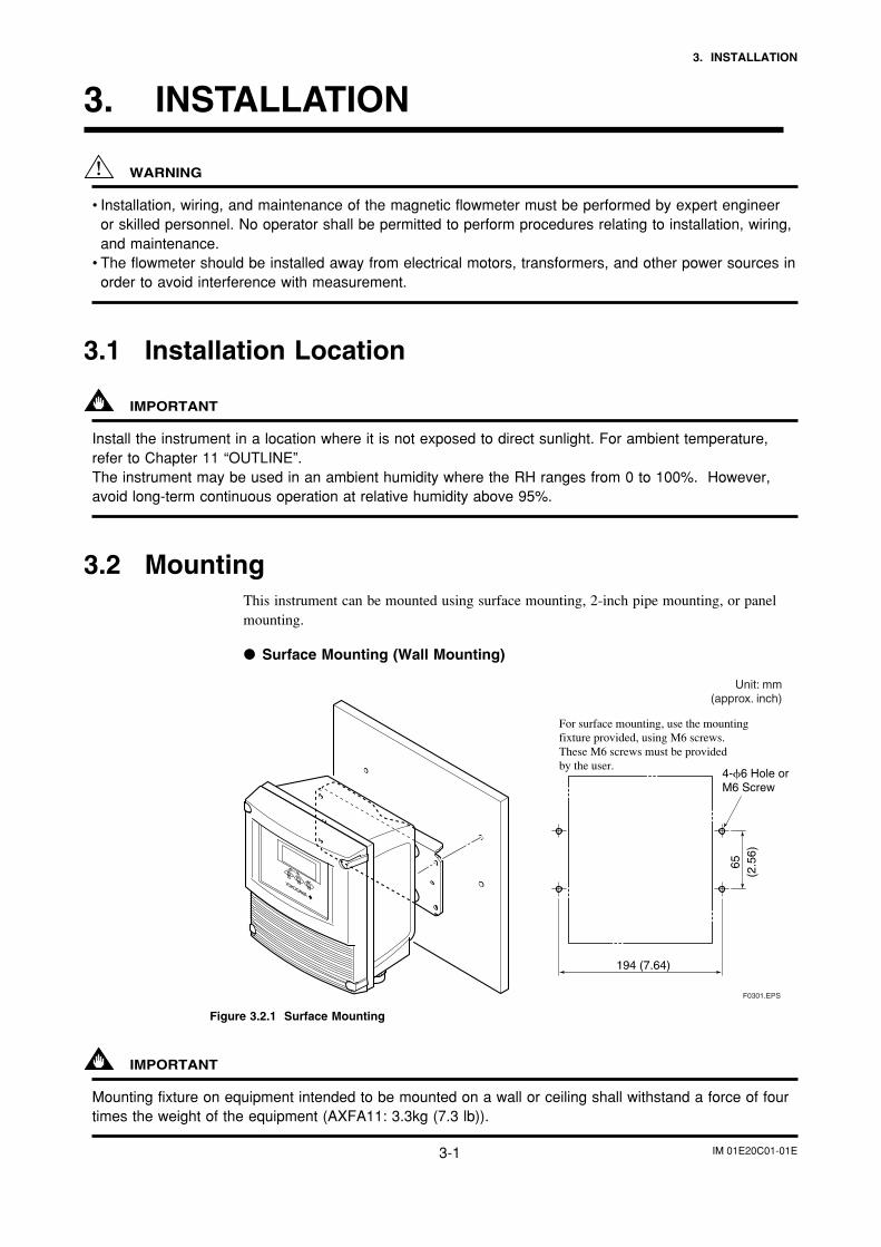
Surface Mounting (Wall Mounting)
4-6 Hole or M6 Screw
194 (7.64)
65(2
.56)
F0301.EPS
For surface mounting, use the mounting fixture provided, using M6 screws. These M6 screws must be providedby the user.
Unit: mm(approx. inch)
Figure 3.2.1 Surface Mounting
IMPORTANT
Mounting fixture on equipment intended to be mounted on a wall or ceiling shall withstand a force of fourtimes the weight of the equipment (AXFA11: 3.3kg (7.3 lb)).
IM 01E20C01-01E3-2
3. INSTALLATION
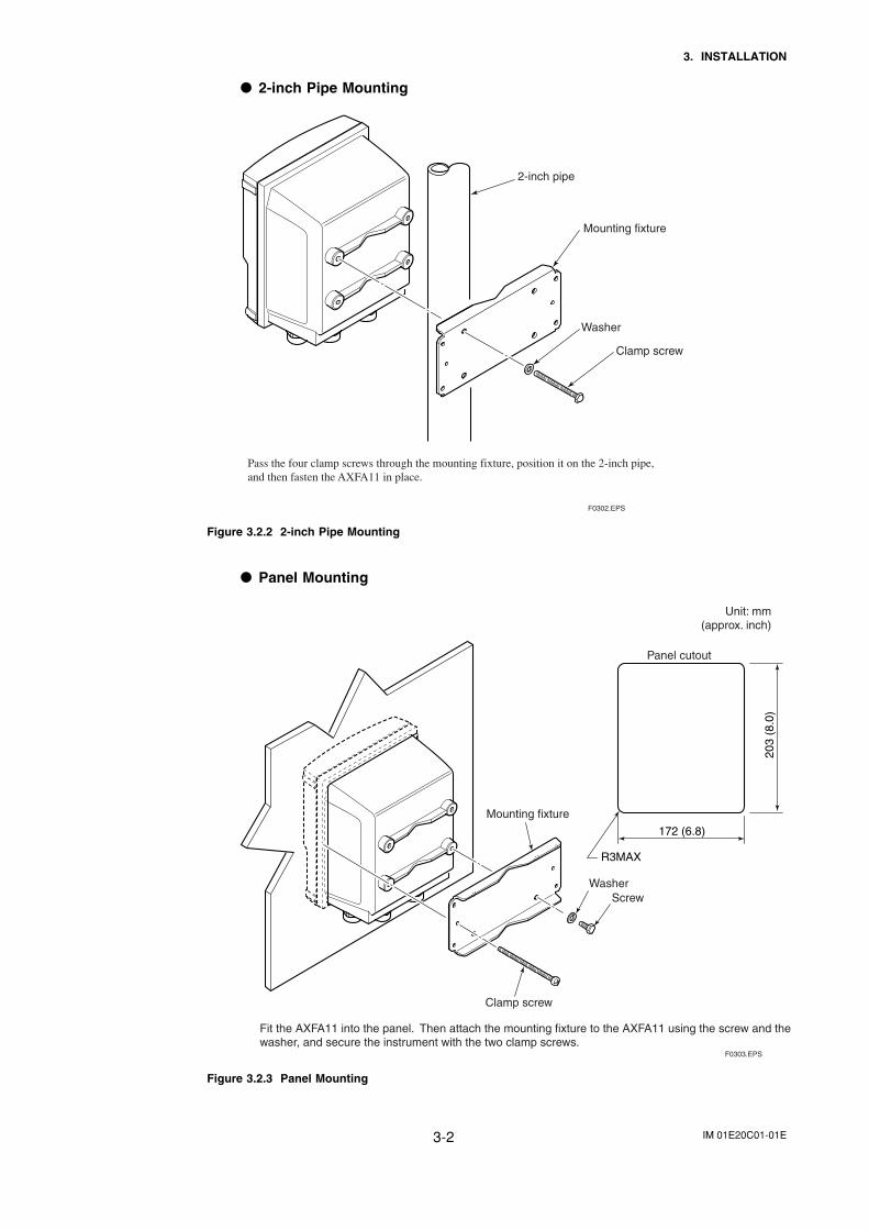
2-inch Pipe Mounting
Pass the four clamp screws through the mounting fixture, position it on the 2-inch pipe, and then fasten the AXFA11 in place.
F0302.EPS
2-inch pipe
Mounting fixture
Washer
Clamp screw
Figure 3.2.2 2-inch Pipe Mounting
Panel Mounting
172 (6.8)
R3MAX
203
(8.0
)
F0303.EPS
Fit the AXFA11 into the panel. Then attach the mounting fixture to the AXFA11 using the screw and the washer, and secure the instrument with the two clamp screws.
Unit: mm(approx. inch)
Mounting fixture
Panel cutout
Washer Screw
Clamp screw
Figure 3.2.3 Panel Mounting
IM 01E20C01-01E4-1
4. WIRING
4. WIRING
This section describes the wiring on the converter sideonly.
NOTE
Read the user’s manual of applicable model aslisted in Table 1.1, for wiring between AXG,AXW or AXF Remote Flowtubes and AXFA11Remote Converter.
WARNING
The wiring of the magnetic flowmeter must beperformed by expert engineer or skilled person-nel. No operator shall be permitted to performprocedures relating to wiring.
CAUTION
Once all wiring is complete, check the connec-tions before applying power to the instrument.Improper arrangements or wiring may cause aunit malfunction or damage.
4.1 Wiring PrecautionsBe sure to observe the following precautions whenwiring:
WARNING
• In cases where the ambient temperatureexceeds 50°C (122°F), use external heat-resistant wiring with a maximum allowabletemperature of 70°C (158°F) or above.
• Do not connect cables outdoors in wet weatherin order to prevent condensation and to protectthe insulation, e.g. inside the terminal box ofthe flowmeter.
• Do not splice the cable between the flowtubeterminal and the converter if it is too short.Replace the short cable with a cable that is theappropriate length.
• Wiring work should be done adequate wire,sleeve crimp and torque force. Use insulatingsleeve crimp terminals (for 4-mm screws) forthe power supply wiring and protective ground-ing ring. Do not pull the wires too muchstrongly in order to prevent electric shockscaused by their damage.
• The signal cables must be routed in separatesteel conduit tubes 16 (JIS C 8305) or flexibleconduit tubes 15 (JIS C 8309).
• Always route the power and output signalcables in separate steel conduit tubes, exceptwhen the power supply voltage is 24 V andfour-core cables are used for wiring. Keepconduits or flexible tubes watertight usingsealing tape.
• Ground the remote flowtube and the converterseparately.
• Cover each shield of the signal cable with vinyltube or vinyl tape to avoid contact between twoshields or between a shield and a case.
• When waterproof glands or union equippedwaterproof glands are used, avoid tighteningthe glands with an excessive torque.
• Be sure to turn power off before opening thecover.
• Before turning the power on, tighten the coversecurely.
IMPORTANT
Prepare the signal cable and the excitation cablealmost the same length. It is recommended tolay them together closely.
IM 01E20C01-01E4-2
4. WIRING
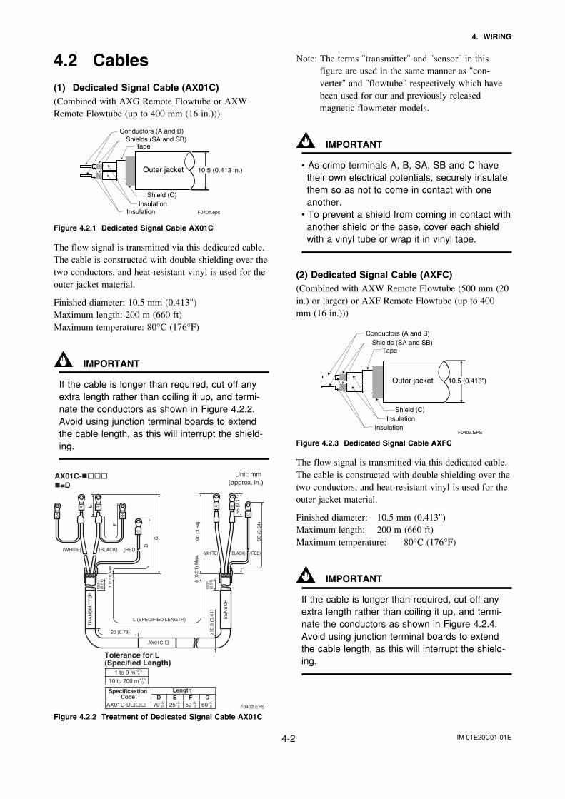
4.2 Cables(1) Dedicated Signal Cable (AX01C)(Combined with AXG Remote Flowtube or AXWRemote Flowtube (up to 400 mm (16 in.)))
F0401.eps
Outer jacket 10.5 (0.413 in.)
Tape
Shield (C)Insulation
Insulation
Shields (SA and SB)Conductors (A and B)
Figure 4.2.1 Dedicated Signal Cable AX01C
The flow signal is transmitted via this dedicated cable.The cable is constructed with double shielding over thetwo conductors, and heat-resistant vinyl is used for theouter jacket material.
Finished diameter: 10.5 mm (0.413")Maximum length: 200 m (660 ft)Maximum temperature: 80°C (176°F)
IMPORTANT
If the cable is longer than required, cut off anyextra length rather than coiling it up, and termi-nate the conductors as shown in Figure 4.2.2.Avoid using junction terminal boards to extendthe cable length, as this will interrupt the shield-ing.
AX01C-=D
F0402.EPS
20 (0.79)
TR
AN
SM
ITT
ER
SE
NS
OR
ø10
.5 (
0.41
)
AX01C-
L (SPECIFIED LENGTH)
150
(5.9
1)8 (0
.31)
Max
.
150
±5
(5.
91)
D
G 90 (
3.54
)
55 (
2.17
)
90 (
3.54
)F
E
SA
SB
A
C
B A
C
B
8 (0
.31)
Max
.
(WHITE) (BLACK) (RED)(WHITE) (BLACK) (RED)
±5
Unit: mm (approx. in.)
Tolerance for L(Specified Length)
1 to 9 m +2%0
10 to 200 m +1%0
AX01C-D 70 +50 25 +5
0 50 +50 60 +5
0
LengthD E F G
SpecificastionCode
Figure 4.2.2 Treatment of Dedicated Signal Cable AX01C
Note: The terms "transmitter" and "sensor" in thisfigure are used in the same manner as "con-verter" and "flowtube" respectively which havebeen used for our and previously releasedmagnetic flowmeter models.
IMPORTANT
• As crimp terminals A, B, SA, SB and C havetheir own electrical potentials, securely insulatethem so as not to come in contact with oneanother.
• To prevent a shield from coming in contact withanother shield or the case, cover each shieldwith a vinyl tube or wrap it in vinyl tape.
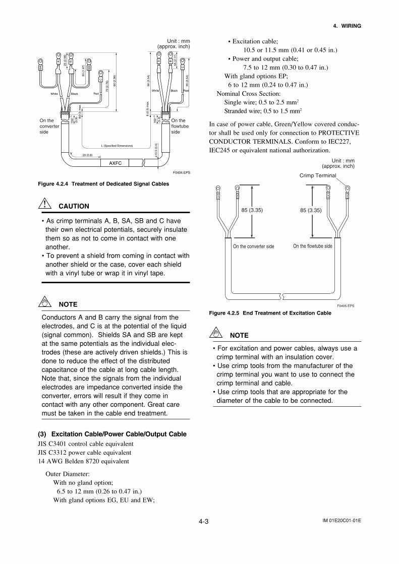
(2) Dedicated Signal Cable (AXFC)(Combined with AXW Remote Flowtube (500 mm (20in.) or larger) or AXF Remote Flowtube (up to 400mm (16 in.)))
Outer jacket 10.5 (0.413")
Tape
Shield (C) Insulation
Insulation
Shields (SA and SB)Conductors (A and B)
F0403.EPS
Figure 4.2.3 Dedicated Signal Cable AXFC
The flow signal is transmitted via this dedicated cable.The cable is constructed with double shielding over thetwo conductors, and heat-resistant vinyl is used for theouter jacket material.
Finished diameter: 10.5 mm (0.413")Maximum length: 200 m (660 ft)Maximum temperature: 80°C (176°F)
IMPORTANT
If the cable is longer than required, cut off anyextra length rather than coiling it up, and termi-nate the conductors as shown in Figure 4.2.4.Avoid using junction terminal boards to extendthe cable length, as this will interrupt the shield-ing.
IM 01E20C01-01E4-3
4. WIRING
20 (0.8) 10
.5 (
0.4)
AXFC
L (Specified Dimensions)
150
58 (0
.3)
max
.
150
5
70 (
2.76
)
60 (
2.36
)
90 (
3.54
)
(5.9
)
(5.9
)
55 (
2.17
)
90 (
3.54
)50 (
1.97
)25 (
0.98
)
SA
SB
A
C
B A
C
B
8(0.
3) m
ax.
White Black RedWhite Black Red
F0404.EPS
Unit : mm(approx. inch)
On theconverterside
On theflowtubeside
Figure 4.2.4 Treatment of Dedicated Signal Cables
CAUTION
• As crimp terminals A, B, SA, SB and C havetheir own electrical potentials, securely insulatethem so as not to come in contact with oneanother.
• To prevent a shield from coming in contact withanother shield or the case, cover each shieldwith a vinyl tube or wrap it in vinyl tape.
NOTE
Conductors A and B carry the signal from theelectrodes, and C is at the potential of the liquid(signal common). Shields SA and SB are keptat the same potentials as the individual elec-trodes (these are actively driven shields.) This isdone to reduce the effect of the distributedcapacitance of the cable at long cable length.Note that, since the signals from the individualelectrodes are impedance converted inside theconverter, errors will result if they come incontact with any other component. Great caremust be taken in the cable end treatment.
(3) Excitation Cable/Power Cable/Output CableJIS C3401 control cable equivalentJIS C3312 power cable equivalent14 AWG Belden 8720 equivalent
Outer Diameter:With no gland option;
6.5 to 12 mm (0.26 to 0.47 in.)With gland options EG, EU and EW;
• Excitation cable;10.5 or 11.5 mm (0.41 or 0.45 in.)
• Power and output cable;7.5 to 12 mm (0.30 to 0.47 in.)
With gland options EP;6 to 12 mm (0.24 to 0.47 in.)
Nominal Cross Section:Single wire; 0.5 to 2.5 mm2
Stranded wire; 0.5 to 1.5 mm2
In case of power cable, Green/Yellow covered conduc-tor shall be used only for connection to PROTECTIVECONDUCTOR TERMINALS. Conform to IEC227,IEC245 or equivalent national authorization.
On the converter side
85 (3.35)E
X1
EX
2
EX
1
EX
2
85 (3.35)
On the flowtube side
Unit : mm(approx. inch)
F0405.EPS
Crimp Terminal
Figure 4.2.5 End Treatment of Excitation Cable
NOTE
• For excitation and power cables, always use acrimp terminal with an insulation cover.
• Use crimp tools from the manufacturer of thecrimp terminal you want to use to connect thecrimp terminal and cable.
• Use crimp tools that are appropriate for thediameter of the cable to be connected.
IM 01E20C01-01E4-4
4. WIRING
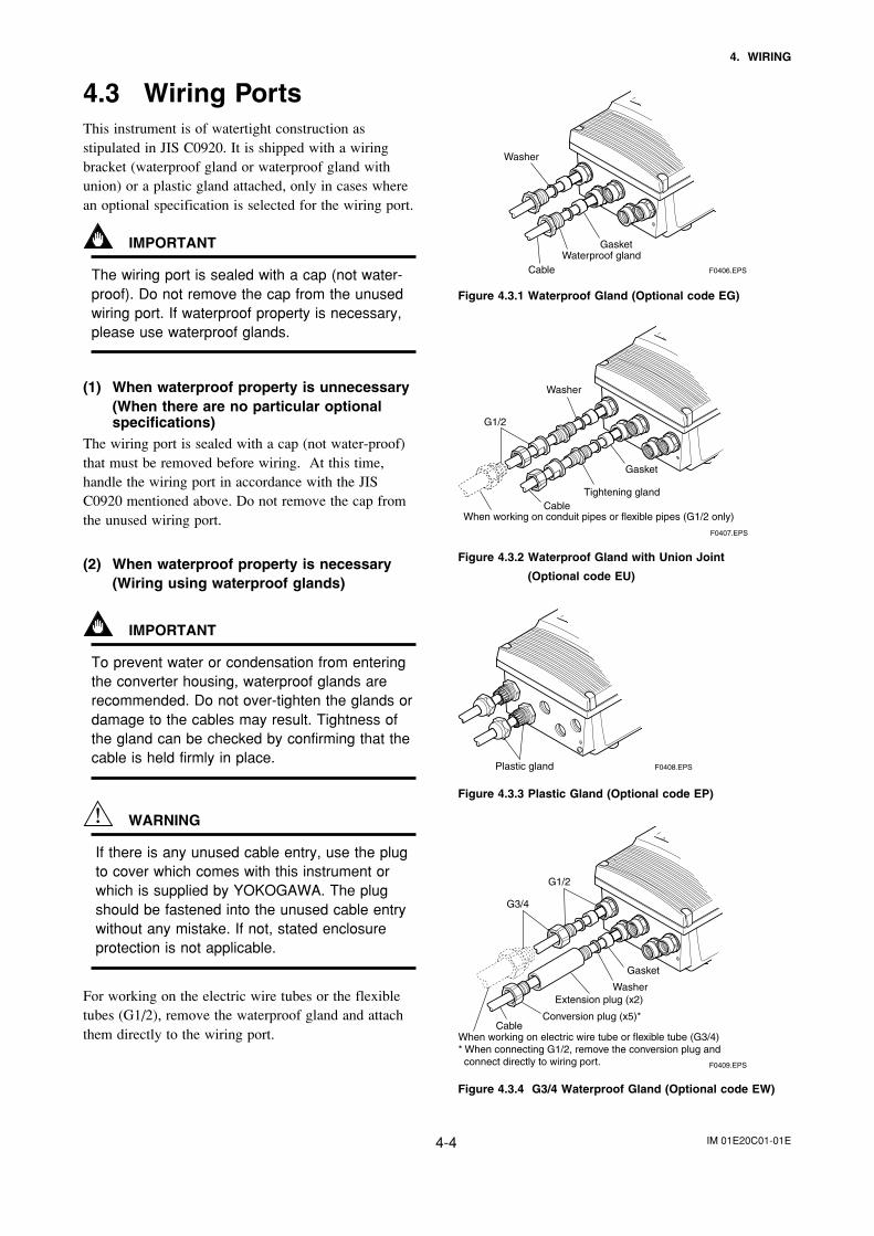
4.3 Wiring PortsThis instrument is of watertight construction asstipulated in JIS C0920. It is shipped with a wiringbracket (waterproof gland or waterproof gland withunion) or a plastic gland attached, only in cases wherean optional specification is selected for the wiring port.
IMPORTANT
The wiring port is sealed with a cap (not water-proof). Do not remove the cap from the unusedwiring port. If waterproof property is necessary,please use waterproof glands.
(1) When waterproof property is unnecessary(When there are no particular optionalspecifications)
The wiring port is sealed with a cap (not water-proof)that must be removed before wiring. At this time,handle the wiring port in accordance with the JISC0920 mentioned above. Do not remove the cap fromthe unused wiring port.
(2) When waterproof property is necessary(Wiring using waterproof glands)
IMPORTANT
To prevent water or condensation from enteringthe converter housing, waterproof glands arerecommended. Do not over-tighten the glands ordamage to the cables may result. Tightness ofthe gland can be checked by confirming that thecable is held firmly in place.
WARNING
If there is any unused cable entry, use the plugto cover which comes with this instrument orwhich is supplied by YOKOGAWA. The plugshould be fastened into the unused cable entrywithout any mistake. If not, stated enclosureprotection is not applicable.
For working on the electric wire tubes or the flexibletubes (G1/2), remove the waterproof gland and attachthem directly to the wiring port.
CableWaterproof gland
Gasket
F0406.EPS
Washer
Figure 4.3.1 Waterproof Gland (Optional code EG)
Gasket
When working on conduit pipes or flexible pipes (G1/2 only)Cable
G1/2
F0407.EPS
Washer
Tightening gland
Figure 4.3.2 Waterproof Gland with Union Joint
(Optional code EU)
Plastic gland F0408.EPS
Figure 4.3.3 Plastic Gland (Optional code EP)
Gasket
When working on electric wire tube or flexible tube (G3/4)* When connecting G1/2, remove the conversion plug and connect directly to wiring port.
Extension plug (x2)
Cable
G3/4
G1/2
Conversion plug (x5)*
F0409.EPS
Washer
Figure 4.3.4 G3/4 Waterproof Gland (Optional code EW)
IM 01E20C01-01E4-5
4. WIRING
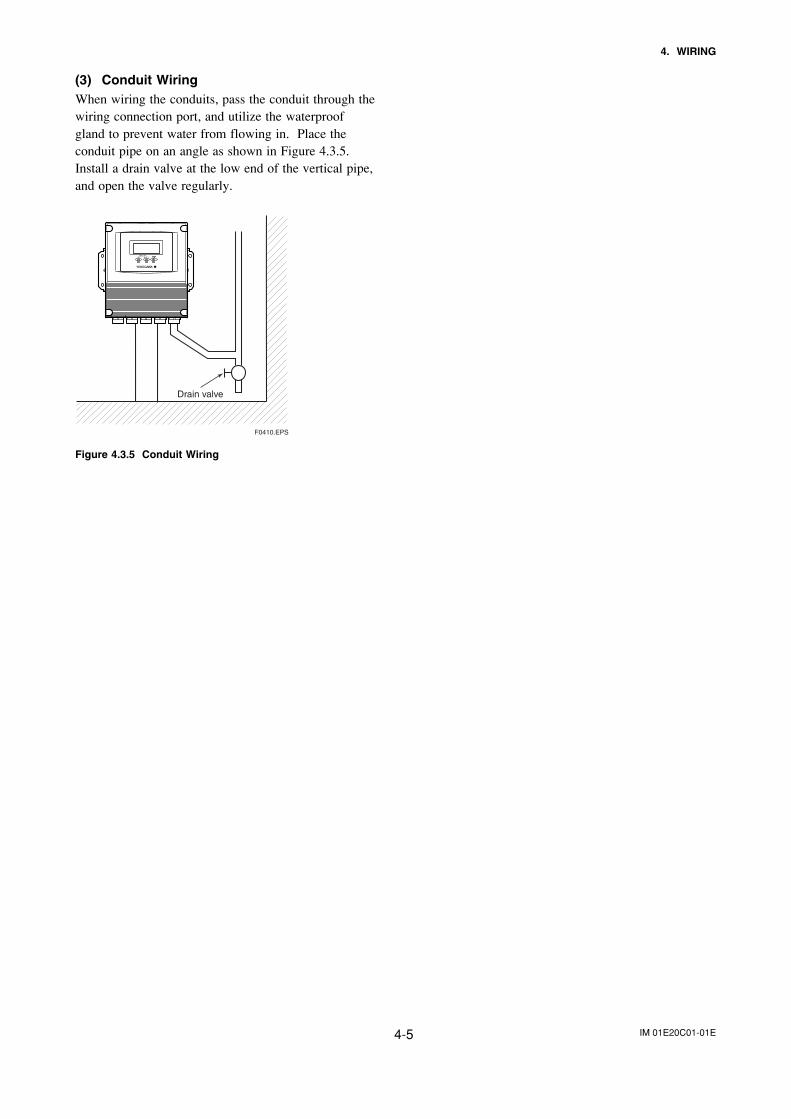
(3) Conduit WiringWhen wiring the conduits, pass the conduit through thewiring connection port, and utilize the waterproofgland to prevent water from flowing in. Place theconduit pipe on an angle as shown in Figure 4.3.5.Install a drain valve at the low end of the vertical pipe,and open the valve regularly.
Drain valve
F0410.EPS
Figure 4.3.5 Conduit Wiring
IM 01E20C01-01E4-6
4. WIRING
4.4 Wiring Connections
WARNING
• Do not open the cover in wet weather or humid environment. When the coveris open, stated enclosure protection is not applicable.
• Do not connect cables outdoors in wet weather in order to prevent condensa-tion and to protect the insulation, e.g. inside the terminal box of the flowmeter.
• This instrument employs the parts which are affected by a function damagecaused by static electricity. Thus, you should do the antistatic work using ananti-static wrist band and be careful to avoid touching each electrical parts andcircuitry directly.
• The cover should be removed by YOKOGAWA’s qualified personnel only.Opening the cover is dangerous, because some areas inside the instrumenthave high voltages.
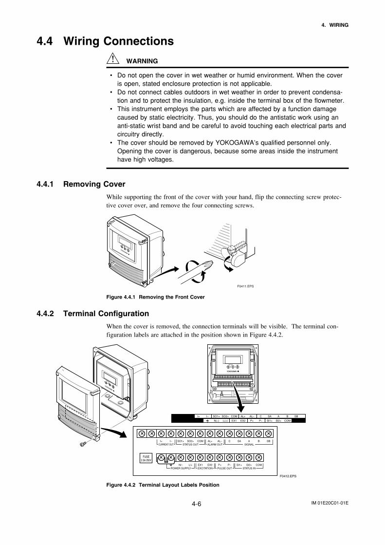
4.4.1 Removing Cover
While supporting the front of the cover with your hand, flip the connecting screw protec-tive cover over, and remove the four connecting screws.
F0411.EPS
Figure 4.4.1 Removing the Front Cover
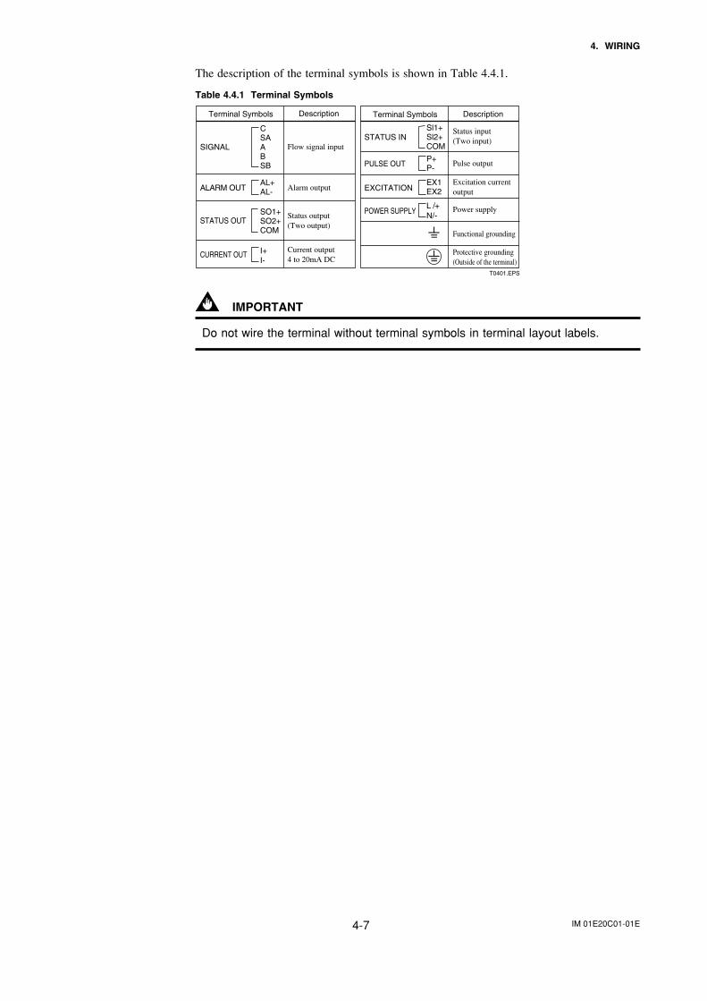
4.4.2 Terminal Configuration
When the cover is removed, the connection terminals will be visible. The terminal con-figuration labels are attached in the position shown in Figure 4.4.2.
F0412.EPS
N(–) L(+) EX2EX1 P– SI1+ SI2+ COMP+
I+ I– AL+ AL– C SA A B SBSO1+ COMSO2+
I+ I–CURRENT OUT
AL+ AL– C SA A B SBALARM OUT
N/– L/+POWER SUPPLY
EX2EX1EXCITATION
P– SI1+ SI2+ COMP+PULSE OUT STATUS IN
SIGNALSO1+ COMSO2+
STATUS OUT
FUSE2.5A 250V
Figure 4.4.2 Terminal Layout Labels Position
IM 01E20C01-01E4-7
4. WIRING
The description of the terminal symbols is shown in Table 4.4.1.
Table 4.4.1 Terminal Symbols
T0401.EPS
Terminal Symbols Description
SIGNAL
CURRENT OUT
Flow signal input
Alarm output
Status output(Two output)
Status input(Two input)
Pulse output
Excitation current output
Power supply
Functional grounding
Protective grounding(Outside of the terminal)
Current output 4 to 20mA DC
ALARM OUT
STATUS OUT
Terminal Symbols Description
STATUS IN
POWER SUPPLY
PULSE OUT
EXCITATION
SO1+SO2+COM
CSAABSB
AL+AL-
I+I-
Sl1+Sl2+COM
P+P-
EX1EX2
L /+N/-
IMPORTANT
Do not wire the terminal without terminal symbols in terminal layout labels.
IM 01E20C01-01E4-8
4. WIRING
4.4.3 Precautions for Wiring of PowerSupply Cables
When connecting to the power supply, observe thepoints below. Failure to comply with these warningsmay result in an electric shock or damage to theinstrument.
WARNING
• Ensure that the power supply is OFF in order toprevent electric shocks.
• Do not open the cover in wet weather or humidenvironment. When the cover is open, statedenclosure protection is not applicable.
• Do not connect cables outdoors in wet weatherin order to prevent condensation and to protectthe insulation, e.g. inside the terminal box ofthe flowmeter.
• Ensure to connect the protective grounding toprevent electric shock before turning ON thepower.
• Never cut off the internal or external protectivegrounding wire or disconnect the wiring of theprotective grounding terminal. Doing so invali-dates the protective functions of the instrumentand poses a potential shock hazard.
• Do not operate the instrument if the protectivegrounding might be defective. Also, ensure tocheck them before operation.
• Connect the protective grounding beforeconnecting to the item under measurement orcontrol unit.
• This instrument employs the parts which areaffected by a function damage caused by staticelectricity. Thus, you should do the antistaticwork using an anti-static wrist band for it andbe careful to avoid touching each electricalparts and circuitry directly.
• Use insulating sleeve crimp terminals (for 4-mmscrews) for the power supply wiring and protec-tive grounding wiring.
• To prevent electric shocks, ensure the electricalwiring cover (transparent) is attached.
• When connecting the wiring, check that thesupply voltage is within the range of the voltagespecified for this instrument before connectingthe power cable. In addition, check that novoltage is applied to the power cable beforeconnecting the wiring.
• Ensure that the source voltage matches thevoltage of the power supply before turning ONthe power.
Power supply code 1;• AC specification: Rated power supply
100 to 240 Vac, 50/60 Hz• DC specification: Rated power supply
100 to 120 VdcPower supply code 2;
• AC specification: Rated power supply 24Vac, 50/60 Hz
• DC specification: Rated power supply 24Vdc
Power consumption:20 W (Combination of AXFA11 RemoteConverter and AXG, AXW and AXFRemote Flowtube each.)Note: The power consumption is the same as above
regardless of the communication type.
• To prevent electric shocks, do not impress overrated voltage to each input/output terminals.
• The cover should be removed byYOKOGAWA’s qualified personnel only. Open-ing the cover is dangerous, because someareas inside the instrument have high voltages.
• Install an external switch or circuit breaker as ameans to turn the power OFF (capacitance; 15A,conforming to IEC60947-1 and IEC60947-3).Locate this switch either near the instrument or inother places facilitating easy operation. Affix a“Power Off Equipment” label to this externalswitch or circuit breaker.
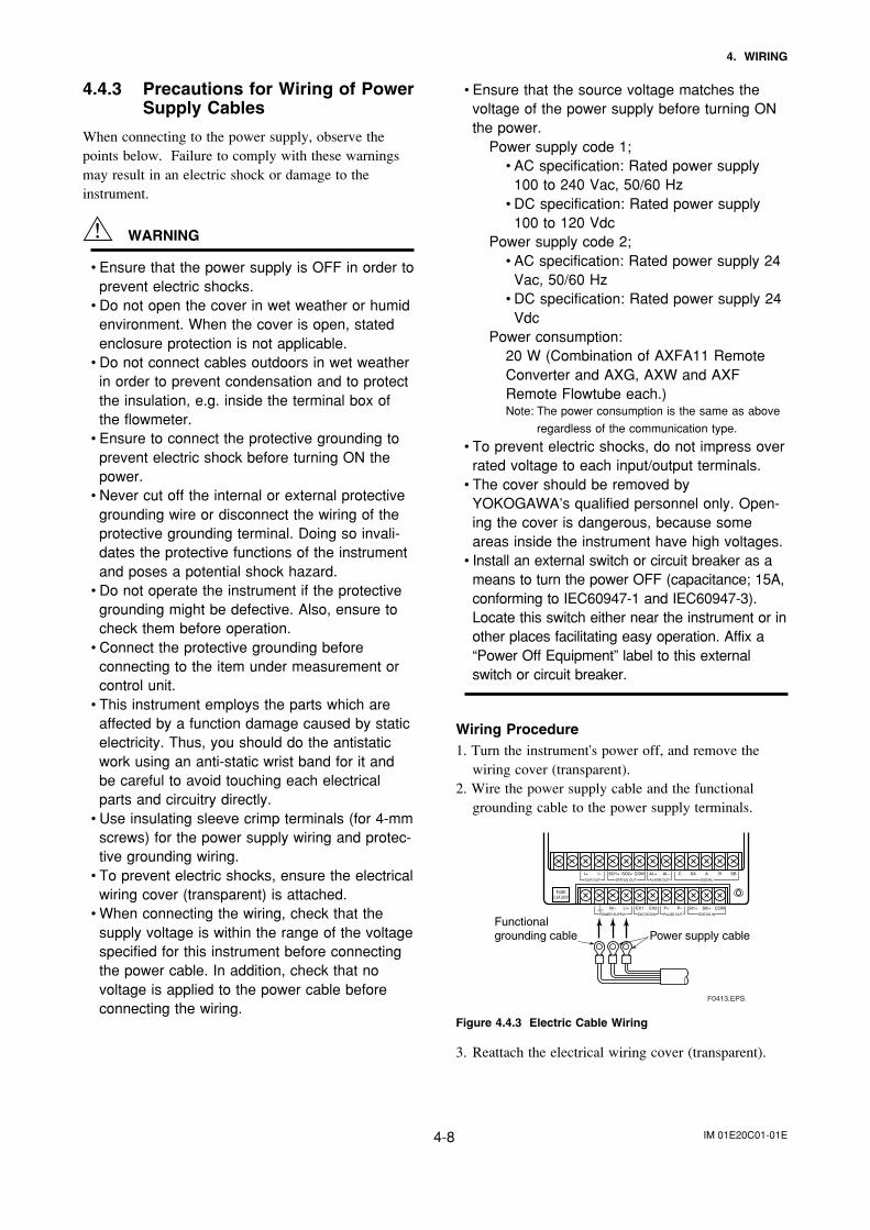
Wiring Procedure1. Turn the instrument's power off, and remove the
wiring cover (transparent).2. Wire the power supply cable and the functional
grounding cable to the power supply terminals.
SBBASACAL–AL+COMSO2+SO1+I+ I–CUR OUT STATUS OUT ALARM OUT SIGNAL
COMSI2+SI1+EX2EX1L/+N/–POWER SUPPLY EXCITATION
P–P+PULSE OUT STATUS IN
Functional grounding cable Power supply cable
F0413.EPS
FUSE2.5A 250V
Figure 4.4.3 Electric Cable Wiring
3. Reattach the electrical wiring cover (transparent).
IM 01E20C01-01E4-9
4. WIRING
4.4.5 Grounding
CAUTION
Be sure to connect the protective grounding ofthe AXFA11 with a cable of 2mm2 or larger crosssection in oder to avoid electrical shock to theoperators and maintenance engineers and toprevent the influence of external noise. Connectthe grounding wire to the mark (100 orless).
IMPORTANT
When optional code A (lightning protector) isselected, the ground should satisfy Class Crequirements (grounding resistance, 10 orless).
• The protective grounding terminals are locatedon the inside and outside of the terminal area.Either terminal may be used.
• Use 600 V vinyl insulation wires as the groundingwires.
F0415.EPSProtective grounding terminals
Figure 4.4.4 Protective Grounding Terminal Location
4.4.4 DC Power Connection
When using DC power as the power supply for theconverter, give attention to the following points.
(1) Connecting Power Supply
IMPORTANT
Do not connect power supply with reversed polarities.L/+ terminal: connect +N/– terminal: connect –
IMPORTANT
Do not connect power supply with 100 to 240 VAC or 100 to 120 V DC in the case of a 24 Vpower supply version (power supply code 2).It will give a damage to the converter.
(2) Required Power Supply Voltages
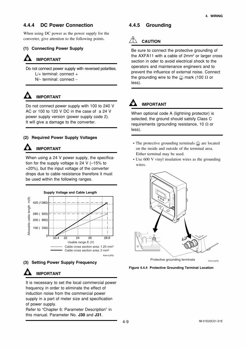
IMPORTANT
When using a 24 V power supply, the specifica-tion for the supply voltage is 24 V (–15% to+20%), but the input voltage of the converterdrops due to cable resistance therefore it mustbe used within the following ranges.
Supply Voltage and Cable Length
020.4 22 24 26 28.8
100 ( 330)
200 ( 660)
280 ( 920)
420 (1380)
F0414.EPS
Cable cross section area: 1.25 mm2
Cable cross section area: 2 mm2
Allo
wab
le c
able
leng
th m
(ft)
Usable range E (V)
(3) Setting Power Supply Frequency
IMPORTANT
It is necessary to set the local commercial powerfrequency in order to eliminate the effect ofinduction noise from the commercial powersupply in a part of meter size and specificationof power supply.Refer to “Chapter 6: Parameter Description” inthis manual. Parameter No. J30 and J31.
IM 01E20C01-01E4-10
4. WIRING
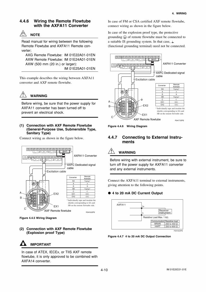
In case of FM or CSA certified AXF remote flowtube,connect wiring as shown in the figure below.
In case of the explosion proof type, the protectivegrounding of remote flowtube must be connected toa suitable IS grounding system. In that case, (functional grounding terminal) need not be connected.
I+ I–CURRENT OUT
AL+ AL– C SA A B SBALARM OUT
N/– L/+POWER SUPPLY
EX2EX1EXCIT ATION
P– SI1+ SI2+ COMP+PULSE OUT STATUS IN
SIGNALSO1+ COMSO2+
STATUS OUT
AXFA11 Converter
AXFC Dedicated signalcable
Converter Remoteflowtube
F0417.EPS
SA
A
B
SB
C
EX1
EX2
Taping*
A
B
Taping*
C
EX1
EX2
* Individually tape and insulate the shields corresponding to SA and SB on the remote flowtube side.
Excitation cable
EX2
EX1
A
B
CAXF Remote flowtube
FUSE2.5A 250V
Figure 4.4.6 Wiring Diagram
4.4.7 Connecting to External Instru-ments
WARNING
Before wiring with external instrument, be sure toturn off the power supply for AXFA11 converterand any external instruments.
Connect the AXFA11 terminal to external instruments,giving attention to the following points.
4 to 20 mA DC Current Output
Resistive Load Max. 1 kΩ.
Receiver Instrument
AXFA11l+
l-
F0418.EPS
Communication Resistive loadBRAINHART
250 to 450 Ω250 to 600 Ω
Figure 4.4.7 4 to 20 mA DC Output Connection
4.4.6 Wiring the Remote Flowtubewith the AXFA11 Converter
NOTE
Read manual for wiring between the followingRemote Flowtube and AXFA11 Remote con-verter;
AXG Remote Flowtube: IM 01E22A01-01ENAXW Remote Flowtube: IM 01E24A01-01ENAXW (500 mm (20 in.) or larger):
IM 01E25A01-01EN
This example describes the wiring between AXFA11converter and AXF remote flowtube.
WARNING
Before wiring, be sure that the power supply forAXFA11 converter has been turned off toprevent an electrical shock.
(1) Connection with AXF Remote Flowtube(General-Purpose Use, Submersible Type,Sanitary Type)
Connect wiring as shown in the figure below.
I+ I–CURRENT OUT
AL+ AL– C SA A B SBALARM OUT
N/– L/+POWER SUPPLY
EX2EX1EXCIT ATION
P– SI1+ SI2+ COMP+PULSE OUT STATUS IN
SIGNALSO1+ COMSO2+
STATUS OUT
AXFA11 Converter
AXF Remote flowtube
AXFC Dedicated signalcable
Converter Remoteflowtube
F0416.EPS
SA
A
B
SB
C
EX1
EX2
Taping*
A
B
Taping*
C
EX1
EX2
* Individually tape and insulate the shields corresponding to SA and SB on the remote flowtube side.
EX2
EX1
A
B
C
Excitation cable
FUSE2.5A 250V
Figure 4.4.5 Wiring Diagram
(2) Connection with AXF Remote Flowtube(Explosion proof Type)
IMPORTANT
In case of ATEX, IECEx, or TIIS AXF remoteflowtube, it is only approved to be combined withAXFA14 converter.
IM 01E20C01-01E4-11
4. WIRING
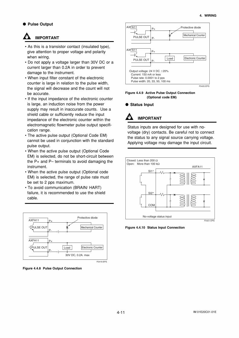
Protective diode
PULSE OUT
AXFA11
AXFA11
P+
P-
P+
P-
Output voltage: 24 V DC 20% Current: 150 mA or less Pulse rate: 0.0001 to 2 pps Pulse width: 20, 33, 50, 100 ms
Mechanical Counter
Electronic CounterLoadPULSE OUT
F0420.EPS
Figure 4.4.9 Active Pulse Output Connection(Optional code EM)
Status Input
IMPORTANT
Status inputs are designed for use with no-voltage (dry) contacts. Be careful not to connectthe status to any signal source carrying voltage.Applying voltage may damage the input circuit.
AXFA11
SI1+
SI2+
COM
F0421.EPS
No-voltage status input
Closed: Less than 200 ΩOpen: More than 100 kΩ
Figure 4.4.10 Status Input Connection
Pulse Output
IMPORTANT
• As this is a transistor contact (insulated type),give attention to proper voltage and polaritywhen wiring.
• Do not apply a voltage larger than 30V DC or acurrent larger than 0.2A in order to preventdamage to the instrument.
• When input filter constant of the electroniccounter is large in relation to the pulse width,the signal will decrease and the count will notbe accurate.
• If the input impedance of the electronic counteris large, an induction noise from the powersupply may result in inaccurate counts. Use ashield cable or sufficiently reduce the inputimpedance of the electronic counter within theelectromagnetic flowmeter pulse output specifi-cation range.
• The active pulse output (Optional Code EM)cannot be used in conjunction with the standardpulse output.
• When the active pulse output (Optional CodeEM) is selected, do not be short-circuit betweenthe P+ and P– terminals to avoid damaging theinstrument.
• When the active pulse output (Optional codeEM) is selected, the range of pulse rate mustbe set to 2 pps maximum.
• To avoid communication (BRAIN/ HART)failure, it is recommended to use the shieldcable.
F0419.EPS
Mechanical Counter
Electronic CounterLoad
Protective diode
30V DC, 0.2A. max
PULSE OUT
PULSE OUT
AXFA11
AXFA11
P+
P-
P+
P-
Figure 4.4.8 Pulse Output Connection
IM 01E20C01-01E4-12
4. WIRING
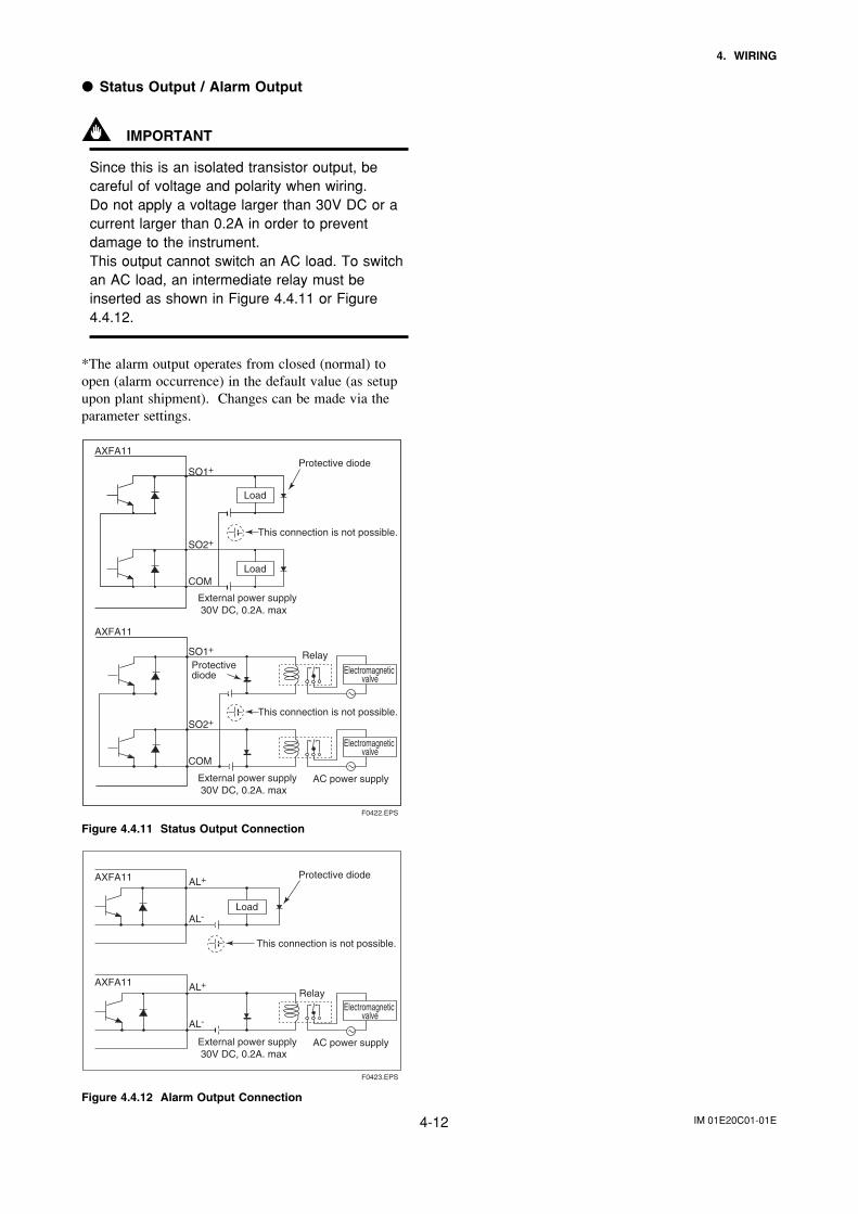
Status Output / Alarm Output
IMPORTANT
Since this is an isolated transistor output, becareful of voltage and polarity when wiring.Do not apply a voltage larger than 30V DC or acurrent larger than 0.2A in order to preventdamage to the instrument.This output cannot switch an AC load. To switchan AC load, an intermediate relay must beinserted as shown in Figure 4.4.11 or Figure4.4.12.
*The alarm output operates from closed (normal) toopen (alarm occurrence) in the default value (as setupupon plant shipment). Changes can be made via theparameter settings.
F0422.EPS
Load
Load
Protective diode
Protective diode
External power supply 30V DC, 0.2A. max
AXFA11
External power supply 30V DC, 0.2A. max
AXFA11
This connection is not possible.
This connection is not possible.
SO1+
SO2+
COM
SO1+
SO2+
COM
Electromagnetic valve
Electromagnetic valve
AC power supply
Relay
Figure 4.4.11 Status Output Connection
F0423.EPS
Load
Protective diode
External power supply 30V DC, 0.2A. max
AXFA11
AXFA11
This connection is not possible.
AL+
AL-
AL+
AL-
Electromagnetic valve
AC power supply
Relay
Figure 4.4.12 Alarm Output Connection
IM 01E20C01-01E5-1
5. BASIC OPERATING PROCEDURES
5. BASIC OPERATING PROCEDURES (USING THE DISPLAY UNIT)
The modification of data settings from the display unit can be carried out using the three
setting switches (infra-red switches) - namely, the , , and switches.The infra-red switches enable the user to set parameters without opening the cover.This chapter will provide a description of basic data configuration and the methods to beused with the three setting switches. The AXFA11 can also be operated using a handheldBrain Terminal (BT200) or a HART Communicator. (Please refer to Chapter 7 for opera-tion via Brain Terminal and Chapter 8 for operation via HART Communicator.)
WARNING
Be sure to set parameters as "Protect" on the write protect function after finish ofparameter setting work.Under extremely rare case, the infra-red switches may respond unexpectedly insuch conditions as sticking ball of water or extraneous substances on the surfaceof display panel glass according to the principle of infra-red switch operation.Its probability rises in such cases as sticking rain water by storm or other similarsituation and washing up work near flowmeter installation place.Either to illuminate or stop illuminating the infra-red switches by the flashlight maycause the mis-reaction.Refer to Chapter 6 "Menu P: Parameter Protection Items" and section "10.2.3"how to use the write protect function in detail.
IMPORTANT
Operate the display unit under the condition where direct sunlight, etc... do not shineto the setting switches directly when the parameter setting operation is carried out.
NOTE
• Always use the setting switches with the cover of the AXFA11 closed.• Use these switches with them covered by the glass window.• If dirt, dust or other substances surfaces on the display panel glass, wipe them
clean with a soft dry cloth.• The operation with dirty gloves may cause a switch response error.
IM 01E20C01-01E5-2
5. BASIC OPERATING PROCEDURES
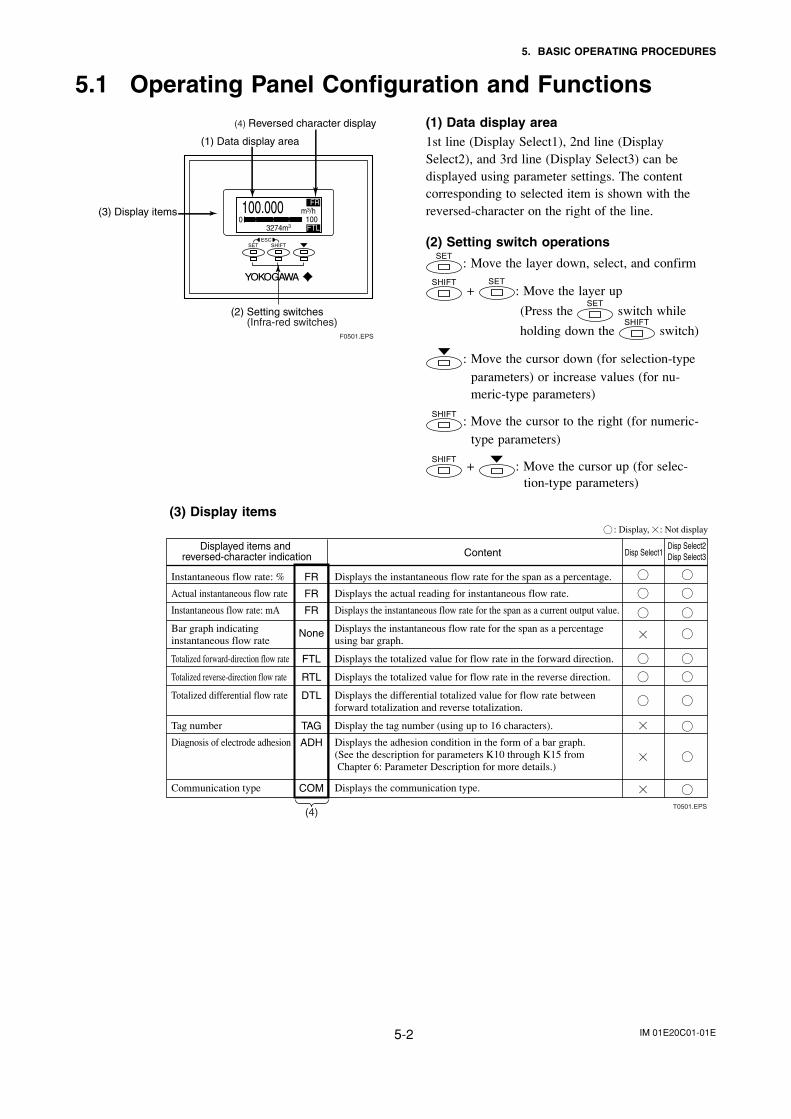
5.1 Operating Panel Configuration and Functions(1) Data display area1st line (Display Select1), 2nd line (DisplaySelect2), and 3rd line (Display Select3) can bedisplayed using parameter settings. The contentcorresponding to selected item is shown with thereversed-character on the right of the line.
(2) Setting switch operations
: Move the layer down, select, and confirm
+ : Move the layer up
(Press the switch while
holding down the switch)
: Move the cursor down (for selection-typeparameters) or increase values (for nu-meric-type parameters)
: Move the cursor to the right (for numeric-type parameters)
+ : Move the cursor up (for selec-tion-type parameters)
(3) Display items
Displayed items and reversed-character indication
T0501.EPS
Displays the instantaneous flow rate for the span as a percentage.
Displays the actual reading for instantaneous flow rate.
Displays the instantaneous flow rate for the span as a current output value.
Displays the instantaneous flow rate for the span as a percentage using bar graph.
Displays the totalized value for flow rate in the forward direction.
Displays the totalized value for flow rate in the reverse direction.
Displays the differential totalized value for flow rate between forward totalization and reverse totalization.
Display the tag number (using up to 16 characters).
Displays the adhesion condition in the form of a bar graph.(See the description for parameters K10 through K15 from Chapter 6: Parameter Description for more details.)
Displays the communication type.
Content Disp Select1Disp Select2Disp Select3
Instantaneous flow rate: %
Actual instantaneous flow rate
Instantaneous flow rate: mA
Bar graph indicating instantaneous flow rate
Totalized forward-direction flow rate
Totalized reverse-direction flow rate
Totalized differential flow rate
Tag number
Diagnosis of electrode adhesion
Communication type
FR
FR
FR
None
FTL
RTL
DTL
TAG
ADH
COM
: Display, : Not display
(4)
F0501.EPS
(4) Reversed character display
(3) Display items
(2) Setting switches
(1) Data display area
(Infra-red switches)
FR m3/h
: : : 100 3274m3 FTL
0
IM 01E20C01-01E5-3
5. BASIC OPERATING PROCEDURES
5.2 Display Unit Setting Methods
NOTE
Before changing any settings, be sure to check the corresponding setting detailsin Chapter 6: Parameter Description.
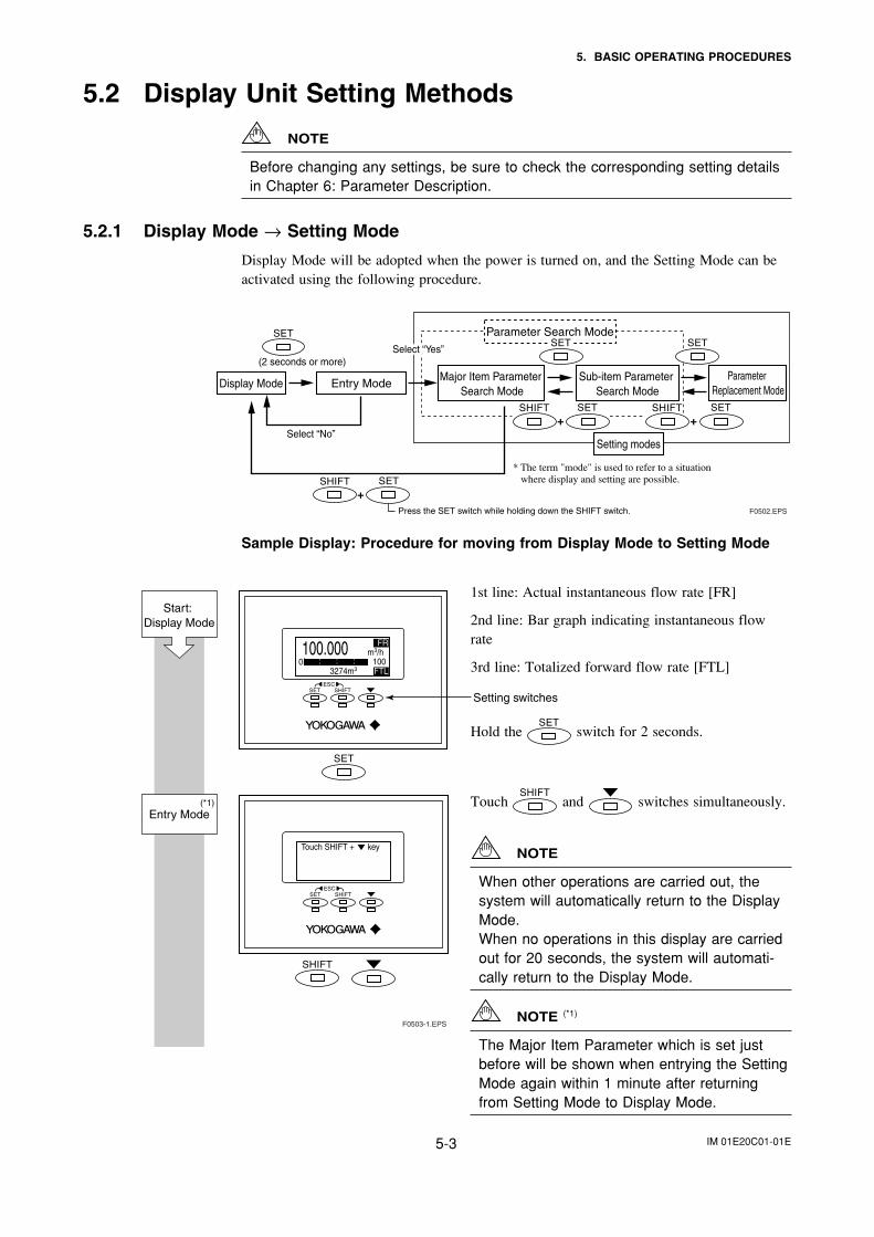
5.2.1 Display Mode → Setting Mode
Display Mode will be adopted when the power is turned on, and the Setting Mode can beactivated using the following procedure.
(2 seconds or more)
Select “No”
Press the SET switch while holding down the SHIFT switch.
Display Mode Entry Mode
Parameter Search Mode
Major Item Parameter Search Mode
Sub-item Parameter Search Mode
Parameter Replacement Mode
Setting modes
F0502.EPS
+
+ +
* The term "mode" is used to refer to a situation where display and setting are possible.
Select “Yes”
Sample Display: Procedure for moving from Display Mode to Setting Mode
1st line: Actual instantaneous flow rate [FR]
2nd line: Bar graph indicating instantaneous flowrate
3rd line: Totalized forward flow rate [FTL]
Hold the switch for 2 seconds.
Touch and switches simultaneously.
NOTE
When other operations are carried out, thesystem will automatically return to the DisplayMode.When no operations in this display are carriedout for 20 seconds, the system will automati-cally return to the Display Mode.
NOTE (*1)
The Major Item Parameter which is set justbefore will be shown when entrying the SettingMode again within 1 minute after returningfrom Setting Mode to Display Mode.
Touch SHIFT + key
FR m3/h
: : : 100 3274m3 FTL
0
F0503-1.EPS
Setting switches
Start: Display Mode
Entry Mode(*1)
IM 01E20C01-01E5-4
5. BASIC OPERATING PROCEDURES
Setting Mode Yes
Setting Mode P:Protect
B:Easy Setup C:Basic Setup
Setting Mode
No Yes
Setting Mode
No Yes
F0503-2.EPS
The reversed-character (i.e. the cursor position) indicates the item that is currently selected.
Setting Mode
To Parameter Search Mode
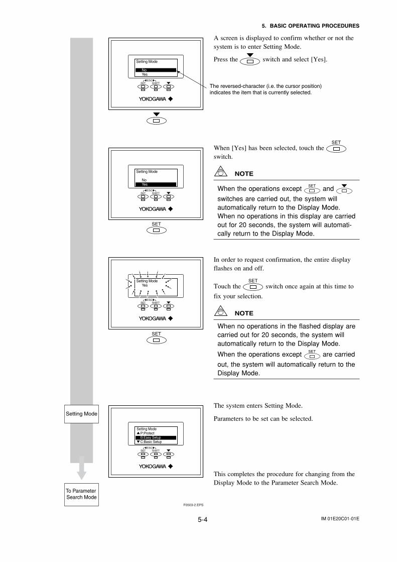
A screen is displayed to confirm whether or not thesystem is to enter Setting Mode.
Press the switch and select [Yes].
When [Yes] has been selected, touch the switch.
NOTE
When the operations except and
switches are carried out, the system willautomatically return to the Display Mode.When no operations in this display are carriedout for 20 seconds, the system will automati-cally return to the Display Mode.
In order to request confirmation, the entire displayflashes on and off.
Touch the switch once again at this time to
fix your selection.
NOTE
When no operations in the flashed display arecarried out for 20 seconds, the system willautomatically return to the Display Mode.
When the operations except are carried
out, the system will automatically return to theDisplay Mode.
The system enters Setting Mode.
Parameters to be set can be selected.
This completes the procedure for changing from theDisplay Mode to the Parameter Search Mode.
IM 01E20C01-01E5-5
5. BASIC OPERATING PROCEDURES
5.2.2 Setting Mode
When the Setting Mode has been activated using the procedure from Section 5.2.1, param-eters can be selected for setting.
NOTE
If no operations are carried out for a period of 10 minutes in Setting Mode, thesystem will automatically return to the Display Mode.
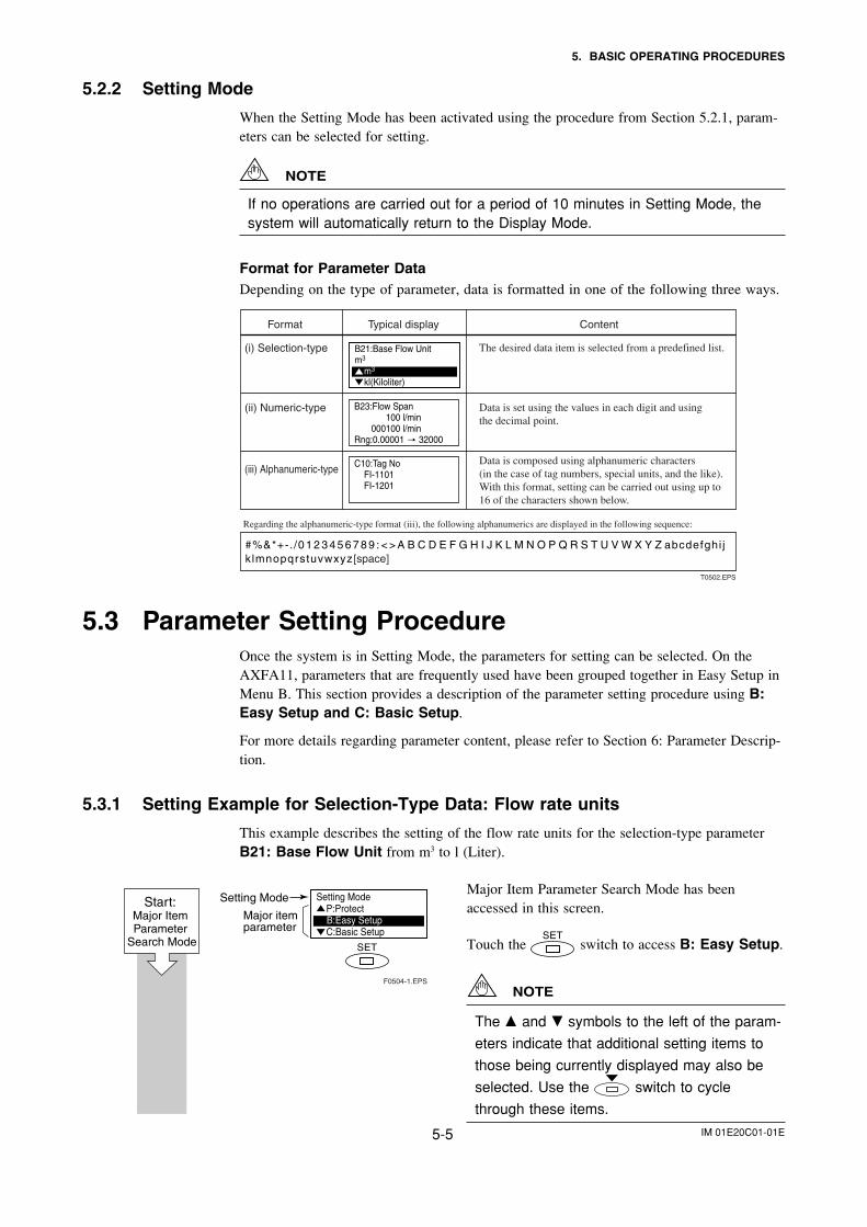
Format for Parameter DataDepending on the type of parameter, data is formatted in one of the following three ways.
B21:Base Flow Unitm3
m3
kl(Kiloliter)
Format Typical display Content
(i) Selection-type The desired data item is selected from a predefined list.
Data is set using the values in each digit and using the decimal point.
Data is composed using alphanumeric characters (in the case of tag numbers, special units, and the like). With this format, setting can be carried out using up to 16 of the characters shown below.
(ii) Numeric-type
(iii) Alphanumeric-type
Regarding the alphanumeric-type format (iii), the following alphanumerics are displayed in the following sequence:
#%&*+-. /0 1 2 3 4 5 6 7 8 9 : < > A B C D E F G H I J K L M N O P Q R S T U V W X Y Z abcdefghi jk lmnopqrstuvwxyz[space]
B23:Flow Span 100 l/min 000100 l/minRng:0.00001 32000
C10:Tag No FI-1101 FI-1201
T0502.EPS
5.3 Parameter Setting ProcedureOnce the system is in Setting Mode, the parameters for setting can be selected. On theAXFA11, parameters that are frequently used have been grouped together in Easy Setup inMenu B. This section provides a description of the parameter setting procedure using B:Easy Setup and C: Basic Setup.
For more details regarding parameter content, please refer to Section 6: Parameter Descrip-tion.
5.3.1 Setting Example for Selection-Type Data: Flow rate units
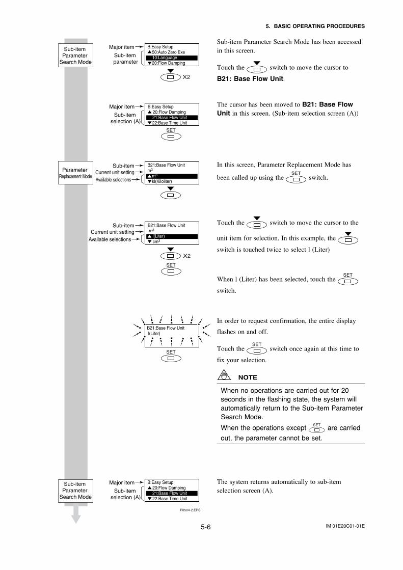
This example describes the setting of the flow rate units for the selection-type parameterB21: Base Flow Unit from m3 to l (Liter).
Major Item Parameter Search Mode has beenaccessed in this screen.
Touch the switch to access B: Easy Setup.
NOTE
The and symbols to the left of the param-
eters indicate that additional setting items to
those being currently displayed may also be
selected. Use the switch to cycle
through these items.
Setting Mode P:Protect
B:Easy Setup C:Basic Setup
F0504-1.EPS
Setting Mode
Major item parameter
Start: Major Item Parameter
Search Mode
IM 01E20C01-01E5-6
5. BASIC OPERATING PROCEDURES
Sub-item Parameter Search Mode has been accessedin this screen.
Touch the switch to move the cursor to
B21: Base Flow Unit.
The cursor has been moved to B21: Base FlowUnit in this screen. (Sub-item selection screen (A))
In this screen, Parameter Replacement Mode has
been called up using the switch.
Touch the switch to move the cursor to the
unit item for selection. In this example, the
switch is touched twice to select l (Liter)
When l (Liter) has been selected, touch the
switch.
In order to request confirmation, the entire display
flashes on and off.
Touch the switch once again at this time to
fix your selection.
NOTE
When no operations are carried out for 20seconds in the flashing state, the system willautomatically return to the Sub-item ParameterSearch Mode.
When the operations except are carried
out, the parameter cannot be set.
The system returns automatically to sub-itemselection screen (A).
F0504-2.EPS
Major item
Sub-item selection (A)
Major item
Sub-item selection (A)
Sub-itemCurrent unit setting
Available selections
Sub-itemCurrent unit settingAvailable selections
B21:Base Flow Unit l(Liter)
X2
X2
Major item
Sub-item parameter
Sub-item Parameter
Search Mode
Parameter Replacement Mode
Sub-item Parameter
Search Mode
B:Easy Setup 20:Flow Damping 21:Base Flow Unit 22:Base Time Unit
B21:Base Flow Unitm3
m3
kl(Kiloliter)
B21:Base Flow Unit m3
l(Liter)cm3
B:Easy Setup20:Flow Damping21:Base Flow Unit22:Base Time Unit
B:Easy Setup 50:Auto Zero Exe
10:Language 20:Flow Damping
IM 01E20C01-01E5-7
5. BASIC OPERATING PROCEDURES
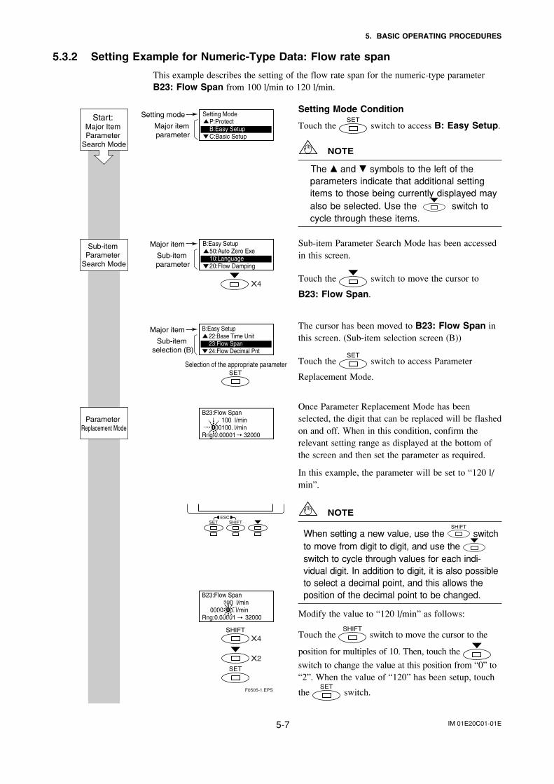
5.3.2 Setting Example for Numeric-Type Data: Flow rate span
This example describes the setting of the flow rate span for the numeric-type parameterB23: Flow Span from 100 l/min to 120 l/min.
Setting Mode Condition
Touch the switch to access B: Easy Setup.
NOTE
The and symbols to the left of theparameters indicate that additional settingitems to those being currently displayed mayalso be selected. Use the switch tocycle through these items.
Sub-item Parameter Search Mode has been accessedin this screen.
Touch the switch to move the cursor to
B23: Flow Span.
The cursor has been moved to B23: Flow Span inthis screen. (Sub-item selection screen (B))
Touch the switch to access Parameter
Replacement Mode.
Once Parameter Replacement Mode has beenselected, the digit that can be replaced will be flashedon and off. When in this condition, confirm therelevant setting range as displayed at the bottom ofthe screen and then set the parameter as required.
In this example, the parameter will be set to “120 l/min”.
NOTE
When setting a new value, use the switchto move from digit to digit, and use the switch to cycle through values for each indi-vidual digit. In addition to digit, it is also possibleto select a decimal point, and this allows theposition of the decimal point to be changed.
Modify the value to “120 l/min” as follows:
Touch the switch to move the cursor to the
position for multiples of 10. Then, touch the
switch to change the value at this position from “0” to“2”. When the value of “120” has been setup, touch
the switch.
Start: Major Item Parameter
Search Mode
F0505-1.EPS
Setting mode
X4
Major item parameter
Major item
Sub-item parameter
Major item
Sub-item selection (B)
X4
X2
Parameter Replacement Mode
Sub-item Parameter
Search Mode
Setting ModeP:ProtectB:Easy SetupC:Basic Setup
B:Easy Setup50:Auto Zero Exe10:Language20:Flow Damping
B:Easy Setup22:Base Time Unit23:Flow Span24:Flow Decimal Pnt
Selection of the appropriate parameter
B23:Flow Span 100 l/min 000100. l/minRng:0.00001 32000
B23:Flow Span 100 l/min 0000100. l/minRng:0.00001 32000
IM 01E20C01-01E5-8
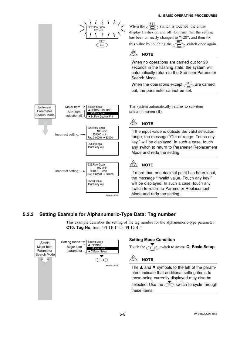
5. BASIC OPERATING PROCEDURES
When the switch is touched, the entire
display flashes on and off. Confirm that the settinghas been correctly changed to “120”, and then fix
this value by touching the switch once again.
NOTE
When no operations are carried out for 20seconds in the flashing state, the system willautomatically return to the Sub-item ParameterSearch Mode.
When the operations except are carried
out, the parameter cannot be set.
The system automatically returns to sub-itemselection screen (B).
NOTE
If the input value is outside the valid selectionrange, the message “Out of range. Touch anykey.” will be displayed. In such a case, touchany switch to return to Parameter ReplacementMode and redo the setting.
NOTE
If more than one decimal point has been input,the message “Invalid value. Touch any key.”will be displayed. In such a case, touch anyswitch to return to Parameter ReplacementMode and redo the setting.
5.3.3 Setting Example for Alphanumeric-Type Data: Tag number
This example describes the setting of the tag number for the alphanumeric-type parameterC10: Tag No. from “FI-1101” to “FI-1201.”
Setting Mode Condition
Touch the switch to access C: Basic Setup.
NOTE
The and symbols to the left of the param-eters indicate that additional setting items tothose being currently displayed may also be
selected. Use the switch to cycle through
these items.
F0505-2.EPS
Major item
Sub-item selection (B)
Incorrect setting:
Incorrect setting:
Out of range.Touch any key.
Invalid value.Touch any key.
Sub-item Parameter
Search Mode
B23:Flow Span 120 l/min
B:Easy Setup22:Base Time Unit23:Flow Span24:Flow Decimal Pnt
B23:Flow Span 100 l/min 1200000 l/minRng:0.00001 32000
B23:Flow Span 100 l/min 0001.0. l/minRng:0.00001 32000
Setting ModeP:ProtectB:Easy SetupC:Basic Setup
F0506-1.EPS
Setting mode
Major item parameter
Start: Major Item Parameter
Search Mode
IM 01E20C01-01E5-9
5. BASIC OPERATING PROCEDURES
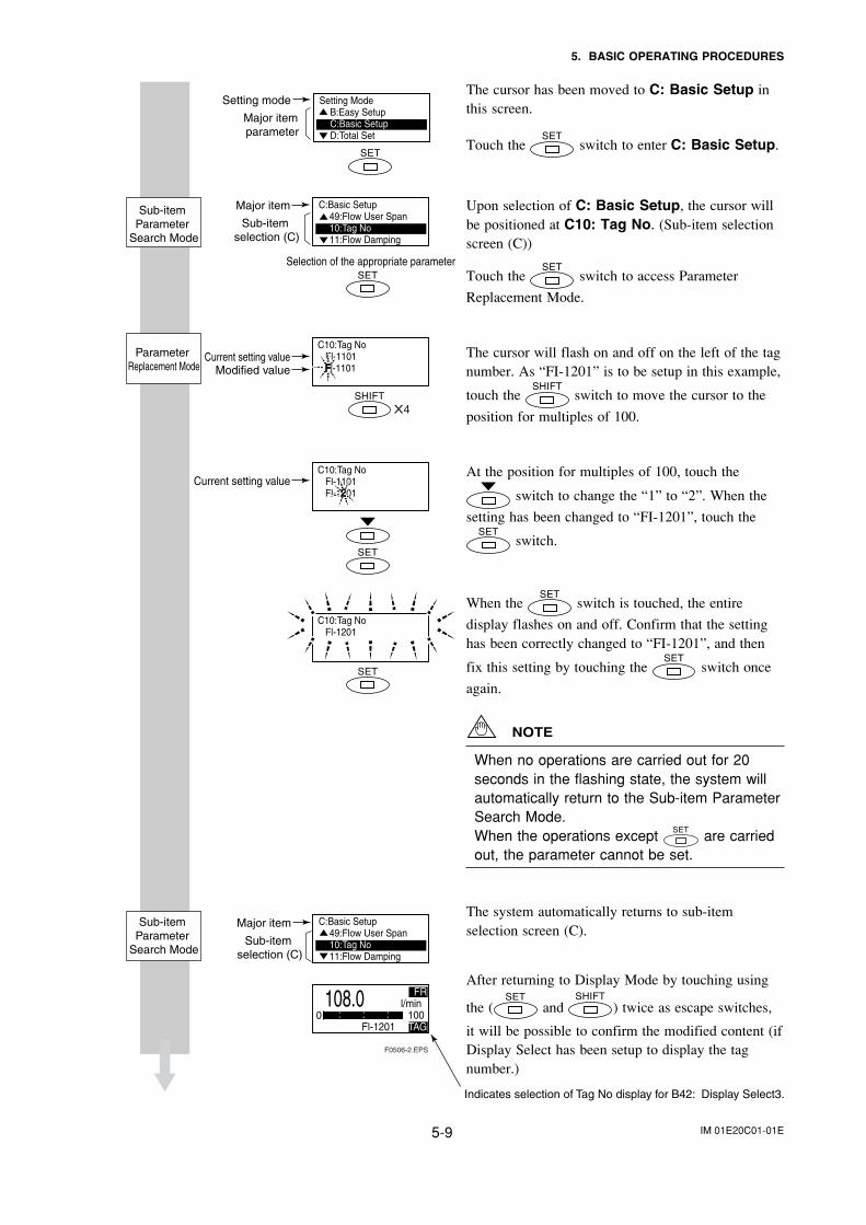
The cursor has been moved to C: Basic Setup inthis screen.
Touch the switch to enter C: Basic Setup.
Upon selection of C: Basic Setup, the cursor willbe positioned at C10: Tag No. (Sub-item selectionscreen (C))
Touch the switch to access Parameter
Replacement Mode.
The cursor will flash on and off on the left of the tagnumber. As “FI-1201” is to be setup in this example,
touch the switch to move the cursor to the
position for multiples of 100.
At the position for multiples of 100, touch the
switch to change the “1” to “2”. When the
setting has been changed to “FI-1201”, touch the
switch.
When the switch is touched, the entire
display flashes on and off. Confirm that the settinghas been correctly changed to “FI-1201”, and then
fix this setting by touching the switch once
again.
NOTE
When no operations are carried out for 20seconds in the flashing state, the system willautomatically return to the Sub-item ParameterSearch Mode.When the operations except are carriedout, the parameter cannot be set.
The system automatically returns to sub-itemselection screen (C).
After returning to Display Mode by touching using
the ( and ) twice as escape switches,
it will be possible to confirm the modified content (ifDisplay Select has been setup to display the tagnumber.)
Selection of the appropriate parameter
C:Basic Setup49:Flow User Span10:Tag No11:Flow Damping
C10:Tag No Fl-1101 l-1101
C10:Tag No Fl-1101 Fl-1 01
C10:Tag No Fl-1201
C:Basic Setup49:Flow User Span10:Tag No11:Flow Damping
108.0 FR l/min
: : : 100 Fl-1201 TAG
0
Setting ModeB:Easy SetupC:Basic SetupD:Total Set
F0506-2.EPS
X4
Major item
Current setting value
Current setting value
Modified value
Sub-item selection (C)
Major item
Sub-item selection (C)
Indicates selection of Tag No display for B42: Display Select3.
Sub-item Parameter
Search Mode
Parameter Replacement Mode
Sub-item Parameter
Search Mode
Setting mode
Major item parameter
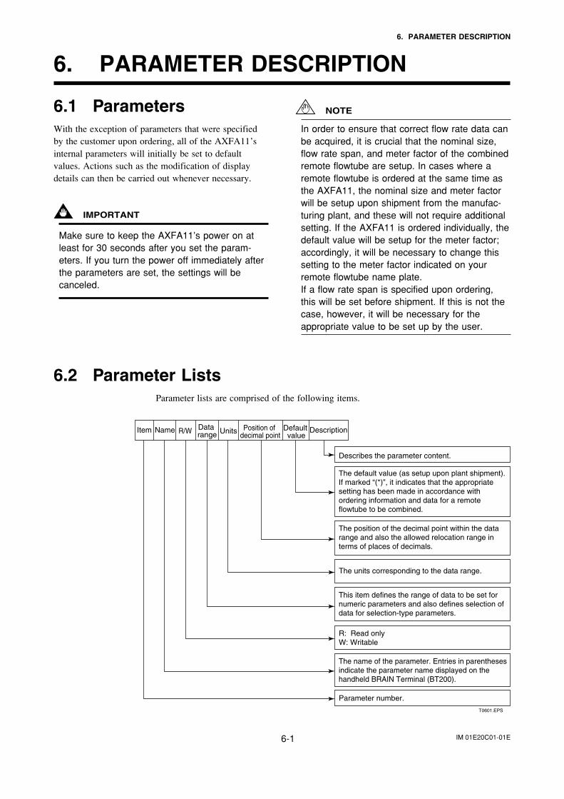
IM 01E20C01-01E6-1
6. PARAMETER DESCRIPTION
6. PARAMETER DESCRIPTION
6.1 ParametersWith the exception of parameters that were specifiedby the customer upon ordering, all of the AXFA11’sinternal parameters will initially be set to defaultvalues. Actions such as the modification of displaydetails can then be carried out whenever necessary.
IMPORTANT
Make sure to keep the AXFA11’s power on atleast for 30 seconds after you set the param-eters. If you turn the power off immediately afterthe parameters are set, the settings will becanceled.
NOTE
In order to ensure that correct flow rate data canbe acquired, it is crucial that the nominal size,flow rate span, and meter factor of the combinedremote flowtube are setup. In cases where aremote flowtube is ordered at the same time asthe AXFA11, the nominal size and meter factorwill be setup upon shipment from the manufac-turing plant, and these will not require additionalsetting. If the AXFA11 is ordered individually, thedefault value will be setup for the meter factor;accordingly, it will be necessary to change thissetting to the meter factor indicated on yourremote flowtube name plate.If a flow rate span is specified upon ordering,this will be set before shipment. If this is not thecase, however, it will be necessary for theappropriate value to be set up by the user.
6.2 Parameter ListsParameter lists are comprised of the following items.
Item Name Data range
Default value
Units Position of decimal point
R/W Description
T0601.EPS
Describes the parameter content.
The units corresponding to the data range.
R: Read only W: Writable
Parameter number.
The default value (as setup upon plant shipment). If marked “(*)”, it indicates that the appropriate setting has been made in accordance with ordering information and data for a remote flowtube to be combined.
This item defines the range of data to be set for numeric parameters and also defines selection of data for selection-type parameters.
The position of the decimal point within the data range and also the allowed relocation range in terms of places of decimals.
The name of the parameter. Entries in parentheses indicate the parameter name displayed on the handheld BRAIN Terminal (BT200).
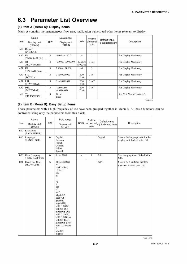
IM 01E20C01-01E6-2
6. PARAMETER DESCRIPTION
6.3 Parameter List Overview(1) Item A (Menu A): Display itemsMenu A contains the instantaneous flow rate, totalization values, and other items relevant to display.
Item
Name
Display unit(BRAIN)
Data range
Display unit/BRAIN
Default value(*): Indicated item
UnitsR/WPosition
of decimal point
Description
T0602.EPS
A00
A10
A20
A21
A30
A31
A32
A60
Display(DISPLAY)
FR(FLOW RATE (%))
FR(FLOW RATE)
FR(FLW RATE (mA))
FTL(TOTAL)
RTL(REV TOTAL)
DTL(DIF TOTAL)—(SELF CHECK)
For Display Mode only
For Display Mode only
For Display Mode only
For Display Mode only
For Display Mode only
For Display Mode only
See “6.5 Alarm Functions”.
-110.0 to 110.0
-999999 to 999999
2.400 to 21.600
0 to 99999999
0 to 99999999
-99999999to 99999999
GoodError
R
R
R
R
R
R
R
%
B21/B22(C40/C41)
mA
B30(D10)
B30(D10)
B30(D10)
1
0 to 3
3
0 to 7
0 to 7
0 to 7
(2) Item B (Menu B): Easy Setup itemsThose parameters with a high frequency of use have been grouped together in Menu B. All basic functions can becontrolled using only the parameters from this block.
T0603-1.EPS
Item
Name
Display unit(BRAIN)
Data range
Display unit/BRAIN
Default value(*): Indicated item
UnitsR/WPosition
of decimal point
Description
B00 Easy Setup(EASY SETUP)
B10 Language(LANGUAGE)
W EnglishJapaneseFrenchGermanItalianSpanish
English Selects the language used for the display unit. Linked with H30.
B21 Base Flow Unit(FLOW UNIT)
W Ml(Megaliter)m3
kl (Kiloliter)l (Liter) cm3
mtkggkcfcfmcf Mgal (US)kgal (US)gal (US)mgal (US)kbbl (US Oil)bbl (US Oil)mbbl (US Oil)ubbl (US Oil)kbbl (US Beer)bbl (US Beer)mbbl (US Beer)ubbl (US Beer)ftklb (US)lb (US)
m (*) Selects flow units for the flow
rate span. Linked with C40.
B20 Flow Damping(FLOW DAMPING)
W 0.1 to 200.0 s 1 3.0 s Sets damping time. Linked with C11.
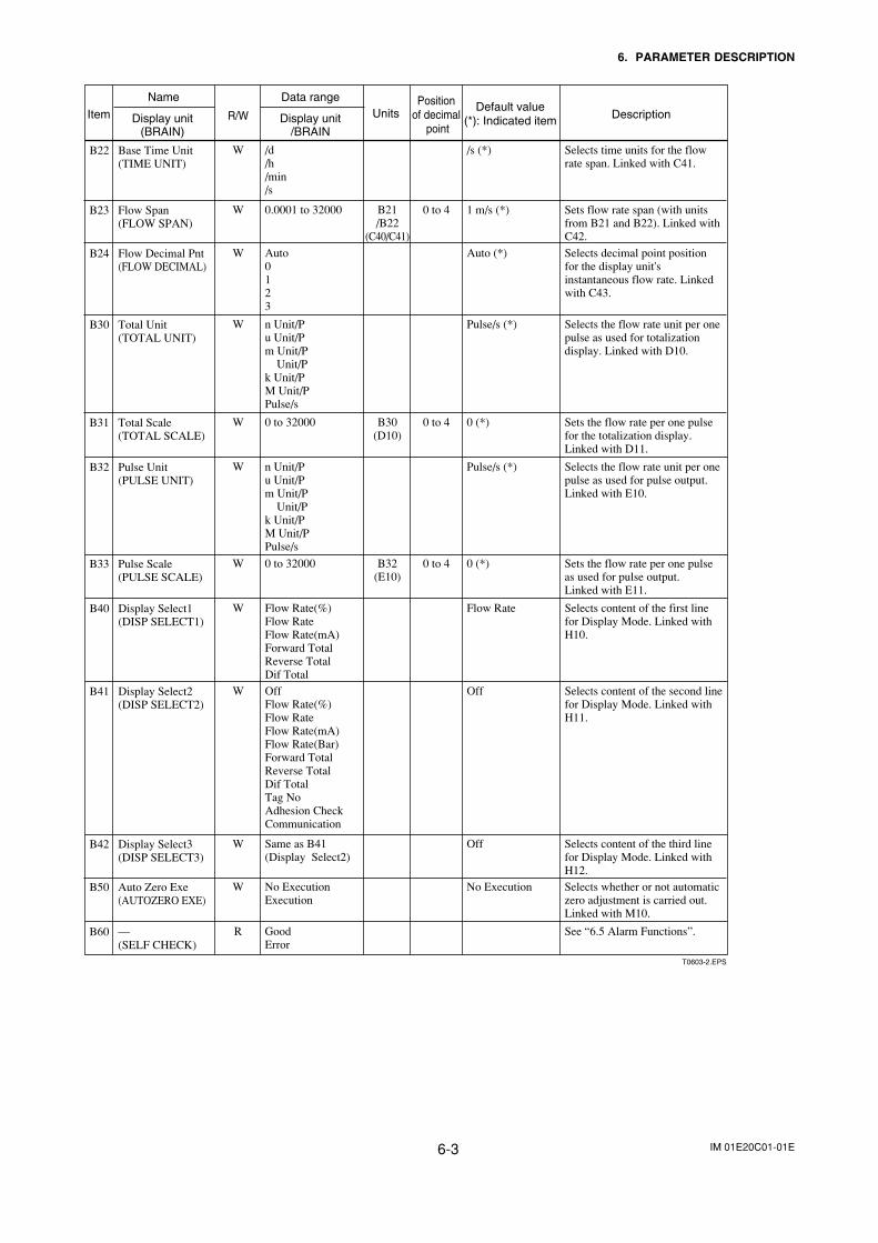
IM 01E20C01-01E6-3
6. PARAMETER DESCRIPTION
Item
Name
Display unit(BRAIN)
Data range
Display unit/BRAIN
Default value(*): Indicated item
UnitsR/WPosition
of decimal point
Description
B22 Base Time Unit(TIME UNIT)
W /d/h/min/s
/s (*) Selects time units for the flow rate span. Linked with C41.
B24 Flow Decimal Pnt(FLOW DECIMAL)
W Auto0123
Auto (*) Selects decimal point position for the display unit's instantaneous flow rate. Linked with C43.
B30 Total Unit(TOTAL UNIT)
W n Unit/Pu Unit/Pm Unit/P Unit/Pk Unit/P M Unit/PPulse/s
Pulse/s (*) Selects the flow rate unit per one pulse as used for totalization display. Linked with D10.
B32 Pulse Unit(PULSE UNIT)
W n Unit/Pu Unit/Pm Unit/P Unit/Pk Unit/P M Unit/PPulse/s
Pulse/s (*) Selects the flow rate unit per one pulse as used for pulse output. Linked with E10.
B23 Flow Span(FLOW SPAN)
W 0.0001 to 32000 B21/B22
(C40/C41)
0 to 4 1 m/s (*) Sets flow rate span (with units from B21 and B22). Linked with C42.
B31 Total Scale(TOTAL SCALE)
W 0 to 32000 B30(D10)
0 to 4 0 (*) Sets the flow rate per one pulse for the totalization display. Linked with D11.
B40 Display Select1(DISP SELECT1)
W Flow Rate(%)Flow RateFlow Rate(mA)Forward TotalReverse TotalDif Total
Flow Rate Selects content of the first line for Display Mode. Linked with H10.
B41 Display Select2(DISP SELECT2)
W OffFlow Rate(%)Flow Rate Flow Rate(mA)Flow Rate(Bar)Forward TotalReverse Total Dif TotalTag No Adhesion CheckCommunication
Off Selects content of the second line for Display Mode. Linked with H11.
B33 Pulse Scale(PULSE SCALE)
W 0 to 32000 B32(E10)
0 to 4 0 (*) Sets the flow rate per one pulse as used for pulse output.Linked with E11.
B42 Display Select3(DISP SELECT3)
W Same as B41(Display Select2)
Off Selects content of the third line for Display Mode. Linked with H12.
B50 Auto Zero Exe(AUTOZERO EXE)
W No ExecutionExecution
No Execution Selects whether or not automatic zero adjustment is carried out. Linked with M10.
B60 —(SELF CHECK)
R GoodError
See “6.5 Alarm Functions”.
T0603-2.EPS
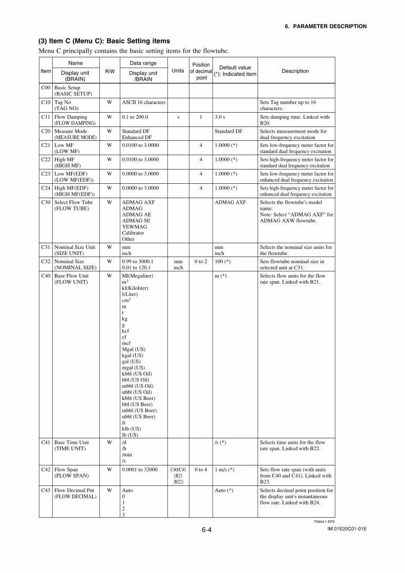
IM 01E20C01-01E6-4
6. PARAMETER DESCRIPTION
(3) Item C (Menu C): Basic Setting itemsMenu C principally contains the basic setting items for the flowtube.
Item
Name
Display unit(BRAIN)
Data range
Display unit/BRAIN
Default value(*): Indicated item
UnitsR/WPosition
of decimal point
Description
T0604-1.EPS
C00
C10
Basic Setup(BASIC SETUP)
Tag No(TAG NO)
Sets Tag number up to 16 characters.
ASCII 16 charactersW
C11 Flow Damping(FLOW DAMPING)
Sets damping time. Linked with B20.
0.1 to 200.0W s
mminch
1
4
3.0 s
C20 Measure Mode(MEASURE MODE)
Selects measurement mode for dual frequency excitation
Standard DFEnhanced DF
W Standard DF
C21 Low MF(LOW MF)
Sets low-frequency meter factor for standard dual frequency excitation
0.0100 to 3.0000W 1.0000 (*)
4C22 High MF(HIGH MF)
Sets high-frequency meter factor for standard dual frequency excitation
0.0100 to 3.0000W 1.0000 (*)
4C23 Low MF(EDF)(LOW MF(EDF))
Sets low-frequency meter factor for enhanced dual frequency excitation
0.0000 to 3.0000W 1.0000 (*)
4C24 High MF(EDF)(HIGH MF(EDF))
Sets high-frequency meter factor for enhanced dual frequency excitation
0.0000 to 3.0000W 1.0000 (*)
C31 Nominal Size Unit(SIZE UNIT)
Selects the nominal size units for the flowtube.
mminch
W mminch
0 to 2C32 Nominal Size(NOMINAL SIZE)
Sets flowtube nominal size in selected unit at C31.
0.99 to 3000.10.01 to 120.1
W 100 (*)
C41 Base Time Unit(TIME UNIT)
Selects time units for the flow rate span. Linked with B22.
/d/h/min/s
W /s (*)
C40/C41(B21/B22)
0 to 4C42 Flow Span(FLOW SPAN)
Sets flow rate span (with units from C40 and C41). Linked with B23.
0.0001 to 32000W 1 m/s (*)
C43 Flow Decimal Pnt(FLOW DECIMAL)
Selects decimal point position for the display unit's instantaneous flow rate. Linked with B24.
Auto0123
W Auto (*)
C30 Select Flow Tube(FLOW TUBE)
Selects the flowtube's model name.Note: Select “ADMAG AXF” for ADMAG AXW flowtube.
ADMAG AXFADMAGADMAG AEADMAG SEYEWMAGCalibratorOther
W ADMAG AXF
C40 Base Flow Unit(FLOW UNIT)
Selects flow units for the flow rate span. Linked with B21.
Ml(Megaliter)m3
kl(Kiloliter)l(Liter)cm3
mtkggkcfcfmcf Mgal (US)kgal (US)gal (US)mgal (US)kbbl (US Oil)bbl (US Oil)mbbl (US Oil)ubbl (US Oil)kbbl (US Beer)bbl (US Beer)mbbl (US Beer)ubbl (US Beer)ftklb (US)lb (US)
W m (*)
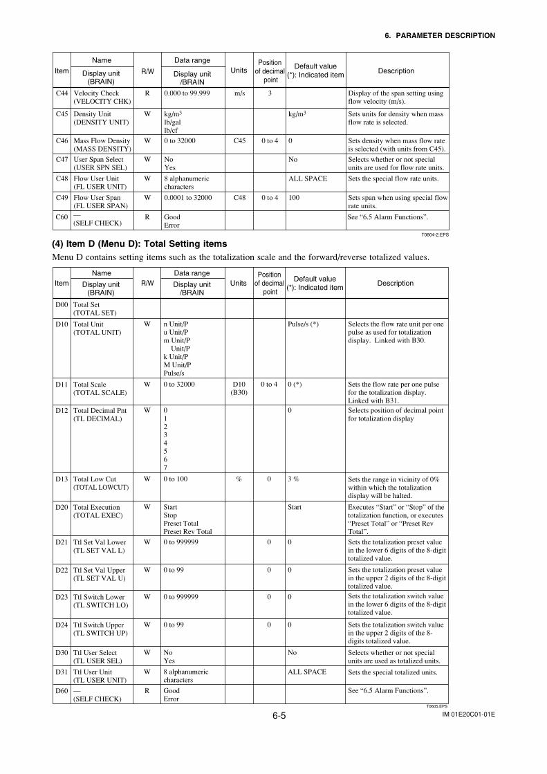
IM 01E20C01-01E6-5
6. PARAMETER DESCRIPTION
Item
Name
Display unit(BRAIN)
Data range
Display unit/BRAIN
Default value(*): Indicated item
UnitsR/WPosition
of decimal point
Description
T0604-2.EPS
C60 —(SELF CHECK)
See “6.5 Alarm Functions”.GoodError
R
m/s 3C44 Velocity Check(VELOCITY CHK)
Display of the span setting using flow velocity (m/s).
0.000 to 99.999R
C45 Density Unit(DENSITY UNIT)
Sets units for density when mass flow rate is selected.
kg/m3
lb/gallb/cf
W kg/m3
C45 0 to 4C46 Mass Flow Density(MASS DENSITY)
Sets density when mass flow rate is selected (with units from C45).
0 to 32000W 0
C47 User Span Select(USER SPN SEL)
Selects whether or not special units are used for flow rate units.
NoYes
W No
ALL SPACEC48 Flow User Unit(FL USER UNIT)
Sets the special flow rate units.8 alphanumericcharacters
W
C48 0 to 4C49 Flow User Span(FL USER SPAN)
Sets span when using special flow rate units.
0.0001 to 32000W 100
(4) Item D (Menu D): Total Setting itemsMenu D contains setting items such as the totalization scale and the forward/reverse totalized values.
T0605.EPS
ItemName
Display unit(BRAIN)
Data range
Display unit/BRAIN
Default value(*): Indicated item
UnitsR/WPosition
of decimal point
Description
D10 Total Unit(TOTAL UNIT)
W n Unit/Pu Unit/Pm Unit/P Unit/Pk Unit/P M Unit/PPulse/s
Pulse/s (*) Selects the flow rate unit per one pulse as used for totalization display. Linked with B30.
D12 Total Decimal Pnt(TL DECIMAL)
W 01234567
0 Selects position of decimal point for totalization display
D11 Total Scale(TOTAL SCALE)
W 0 to 32000 D10(B30)
0 to 4 0 (*) Sets the flow rate per one pulse for the totalization display. Linked with B31.
Sets the range in vicinity of 0% within which the totalization display will be halted.
D13 Total Low Cut(TOTAL LOWCUT)
W 0 to 100 % 0 3 %
Sets the totalization preset value in the lower 6 digits of the 8-digit totalized value.
D21 Ttl Set Val Lower(TL SET VAL L)
W 0 to 999999 0 0
Sets the totalization preset value in the upper 2 digits of the 8-digit totalized value.
D22 Ttl Set Val Upper(TL SET VAL U)
W 0 to 99 0 0
Sets the totalization switch value in the lower 6 digits of the 8-digit totalized value.
D23 Ttl Switch Lower(TL SWITCH LO)
W 0 to 999999 0 0
Sets the totalization switch value in the upper 2 digits of the 8- digits totalized value.
D24 Ttl Switch Upper(TL SWITCH UP)
W 0 to 99 0 0
Selects whether or not special units are used as totalized units.
D30 Ttl User Select(TL USER SEL)
W NoYes
No
Sets the special totalized units.D31 Ttl User Unit(TL USER UNIT)
W 8 alphanumericcharacters
See “6.5 Alarm Functions”.D60 —(SELF CHECK)
R GoodError
Executes “Start” or “Stop” of the totalization function, or executes “Preset Total” or “Preset Rev Total”.
D20 Total Execution(TOTAL EXEC)
W StartStopPreset TotalPreset Rev Total
Start
D00 Total Set(TOTAL SET)
ALL SPACE
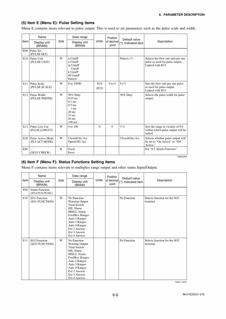
IM 01E20C01-01E6-6
6. PARAMETER DESCRIPTION
(5) Item E (Menu E): Pulse Setting itemsMenu E contains items relevant to pulse output. This is used to set parameters such as the pulse scale and width.
T0606.EPS
Item
Name
Display unit(BRAIN)
Data range
Display unit/BRAIN
Default value(*): Indicated item
UnitsR/WPosition
of decimal point
Description
E10 Pulse Unit(PULSE UNIT)
W n Unit/Pu Unit/Pm Unit/P Unit/Pk Unit/P M Unit/PPulse/s
Pulse/s (*) Selects the flow rate unit per one pulse as used for pulse output. Linked with B32.
E12 Pulse Width(PULSE WIDTH)
W 50% Duty0.05 ms 0.1 ms0.5 ms 1 ms 20 ms33 ms50 ms100 ms
50% Duty Selects the pulse width for pulse output.
E11 Pulse Scale(PULSE SCALE)
W 0 to 32000 E10
(B32)
0 to 4 0 (*) Sets the flow rate per one pulse as used for pulse output.Linked with B33.
E13 Pulse Low Cut(PULSE LOWCUT)
W 0 to 100 % 0 3 % Sets the range in vicinity of 0% within which pulse output will be halted.
E20 Pulse Active Mode(PLS ACT MODE)
W Closed(On) ActOpen(Off) Act
Closed(On) Act Selects whether pulse output will be set to “On Active” or “Off Active.”See “6.5 Alarm Function”.E60 —
(SELF CHECK)R Good
Error
E00 Pulse Set(PULSE SET)
(6) Item F (Menu F): Status Functions Setting itemsMenu F contains items relevant to multiplex range output and other status Input/Output.
T0607-1.EPS
Item
Name
Display unit(BRAIN)
Data range
Display unit/BRAIN
Default value(*): Indicated item
UnitsR/WPosition
of decimal point
Description
F10 SO1 Function(SO1 FUNCTION)
W No FunctionWarning OutputTotal SwitchH/L AlarmHH/LL AlarmFwd/Rev RangesAuto 2 RangesAuto 3 RangesAuto 4 RangesExt 2 AnswerExt 3 AnswerExt 4 Answer
No Function Selects function for the SO1 terminal
F11 SO2 Function(SO2 FUNCTION)
W No FunctionWarning OutputTotal SwitchH/L AlarmHH/LL AlarmFwd/Rev RangesAuto 2 RangesAuto 3 RangesAuto 4 RangesExt 2 AnswerExt 3 AnswerExt 4 Answer
No Function Selects function for the SO2 terminal
F00 Status Function(STATUS FUNC)
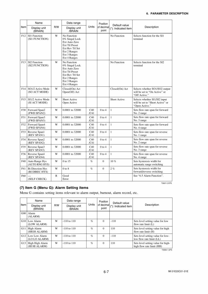
IM 01E20C01-01E6-7
6. PARAMETER DESCRIPTION
T0607-2.EPS
Item
Name
Display unit(BRAIN)
Data range
Display unit/BRAIN
Default value(*): Indicated item
UnitsR/WPosition
of decimal point
Description
F14 SO1/2 Active Mode(SO ACT MODE)
W Closed(On) ActOpen(Off) Act
Closed(On) Act Selects whether SO1/SO2 output will be set to “On Active” or “Off Active.”
F15 SI1/2 Active Mode(SI ACT MODE)
W Short ActiveOpen Active
Short Active Selects whether SI1/SI2 input will be set to “Short Active” or “Open Active.”
F30 Forward Span2(FWD SPAN2)
W C40/C41
0 to 40.0001 to 32000 1 Sets flow rate span for forward No. 2 range
F31 Forward Span3(FWD SPAN3)
W C40/C41
0 to 40.0001 to 32000 1 Sets flow rate span for forward No. 3 range
F32 Forward Span4(FWD SPAN4)
W C40/C41
0 to 40.0001 to 32000 1 Sets flow rate span for forward No. 4 range
F33 Reverse Span1(REV SPAN1)
W C40/C41
0 to 40.0001 to 32000 1 Sets flow rate span for reverse No. 1 range
F34 Reverse Span2(REV SPAN2)
W C40/C41
0 to 40.0001 to 32000 1 Sets flow rate span for reverse No. 2 range
F35 Reverse Span3(REV SPAN3)
W C40/C41
0 to 40.0001 to 32000 1 Sets flow rate span for reverse No. 3 range
F36 Reverse Span4(REV SPAN4)
W C40/C41
0 to 40.0001 to 32000 1 Sets flow rate span for reverse No. 4 range
F40 Auto Range Hys(AUTO RNG HYS)
W % 00 to 15 10 % Sets hysteresis width for automatic range switching
F41 Bi Direction Hys(BI DIREC HYS)
W % 00 to 8 2 % Sets hysteresis width for forward/reverse switching
F12 SI1 Function(SI1 FUNCTION)
W No Function0% Singal LockExt Auto ZeroExt Ttl PresetExt Rev Ttl SetExt 2 RangesExt 3 RangesExt 4 Ranges
No Function Selects function for the SI1 terminal
F13 SI2 Function(SI2 FUNCTION)
W No Function0% Singal LockExt Auto ZeroExt Ttl PresetExt Rev Ttl SetExt 2 RangesExt 3 RangesExt 4 Ranges
No Function Selects function for the SI2 terminal
See “6.5 Alarm Function”.F60 —(SELF CHECK)
R GoodError
(7) Item G (Menu G): Alarm Setting itemsMenu G contains setting items relevant to alarm output, burnout, alarm record, etc.
Item
Name
Display unit(BRAIN)
Data range
Display unit/BRAIN
Default value(*): Indicated item
UnitsR/WPosition
of decimal point
Description
T0608-1.EPS
G00 Alarm(ALARM)
G10 Low Alarm(LOW ALARM)
W % 0-110 to 110 -110 Sets level setting value for low flow rate limit (L)
G11 High Alarm(HIGH ALARM)
W % 0-110 to 110 110 Sets level setting value for high flow rate limit (H)
G12 Low Low Alarm(LO LO ALARM)
W % 0-110 to 110 -110 Sets level setting value for low-low flow rate limit (LL)
G13 High High Alarm(HI HI ALARM)
W % 0-110 to 110 110 Sets level setting value for high-high flow rate limit (HH)
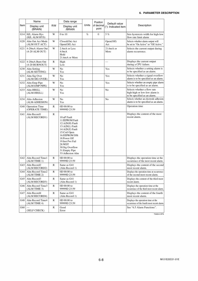
IM 01E20C01-01E6-8
6. PARAMETER DESCRIPTION
T0608-2.EPS
Item
Name
Display unit(BRAIN)
Data range
Display unit/BRAIN
Default value(*): Indicated item
UnitsR/WPosition
of decimal point
Description
G14 H/L Alarm Hys(H/L ALM HYS)
W % 00 to 10 5 % Sets hysteresis width for high-low flow rate limit alarm
G20 Alm Out Act Mode(ALM OUT ACT)
W Closed(On) ActOpen(Off) Act
Open(Off)Act
Selects whether alarm output will be set to “On Active” or “Off Active.”
G22 4-20mA Burn Out(4-20 BURNOUT)
R HighLow
— Displays the current output during a CPU failure.
G30 Alm-Setting(ALM-SETTING)
W NoYes
Yes Selects whether a setting alarm is to be specified as an alarm.
G31 Alm-Sig Over(ALM-SIG OVER)
W NoYes
Yes Selects whether a signal overflow alarm is to be specified as an alarm.
G32 Alm-Emp Pipe(ALM-EMP PIPE)
W NoYes
Yes Selects whether an empty pipe alarmis to be specified as an alarm.
G33 Alm-HH/LL(ALM-HH/LL)
W NoYes
No Selects whether a flow rate high-high or low-low alarm is to be specified as an alarm.
G34 Alm-Adhesion(ALM-ADHESION)
W NoYes
No Selects whether an electrode adhesion alarm is to be specified as an alarm.
G40 Operation Time(OPERATE TIME)
R 0D 00:00 to99999D 23:59
Operation time
G42 Alm Record Time1(ALM TIME 1)
R 0D 00:00 to99999D 23:59
Displays the operation time at the occurrence of the most recent alarm.
G43 Alm Record2(ALM RECORD2)
R Same as G41(Alm Record 1)
Displays the content of the second most recent alarm.
G44 Alm Record Time2(ALM TIME 2)
R 0D 00:00 to99999D 23:59
Displays the operation time at occurrence of the second most recent alarm.
G45 Alm Record3(ALM RECORD3)
R Same as G41(Alm Record 1)
Displays the content of the third most recent alarm.
G46 Alm Record Time3(ALM TIME 3)
R 0D 00:00 to99999D 23:59
Displays the operation time at the occurrence of the third most recent alarm.
G47 Alm Record4(ALM RECORD4)
R Same as G41(Alm Record 1)
Displays the content of the fourth most recent alarm.
G48 Alm Record Time4(ALM TIME 4)
R 0D 00:00 to99999D 23:59
Displays the operation time at the occurrence of the fourth most recent alarm.
G60 —(SELF CHECK)
R GoodError
See “6.5 Alarm Functions”.
G21 4-20mA Alarm Out(4-20 ALM OUT)
W 2.4mA or Less4.0mAHold21.6mA or More
21.6mA orMore
Selects the current output during alarm occurrence.
G41 Alm Record1(ALM RECORD1)
R10:uP Fault11:EEPROM Fault12:A/D(H) Fault13:A/D(L) Fault14:A/D(Z) Fault15:Coil Open16:EEPROM Dflt18:Power Off19:Inst Pwr Fail28:WDT30:Sig Overflow31:Empty Pipe33:Adhesion Alm
Displays the content of the most recent alarm.
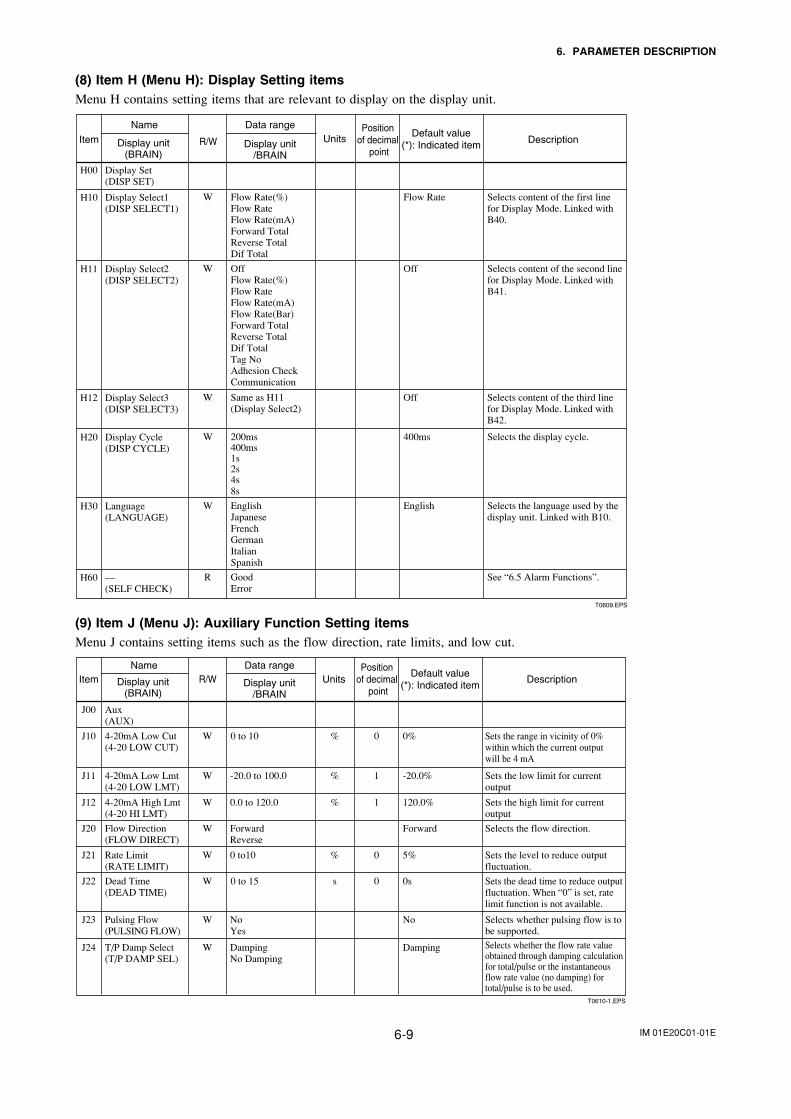
IM 01E20C01-01E6-9
6. PARAMETER DESCRIPTION
(8) Item H (Menu H): Display Setting itemsMenu H contains setting items that are relevant to display on the display unit.
T0609.EPS
Item
Name
Display unit(BRAIN)
Data range
Display unit/BRAIN
Default value(*): Indicated item
UnitsR/WPosition
of decimal point
Description
H10 Display Select1(DISP SELECT1)
W Flow Rate(%)Flow RateFlow Rate(mA)Forward TotalReverse TotalDif Total
Flow Rate Selects content of the first line for Display Mode. Linked with B40.
H20 Display Cycle(DISP CYCLE)
W 200ms400ms1s 2s 4s 8s
400ms Selects the display cycle.
H30 Language(LANGUAGE)
W EnglishJapaneseFrench GermanItalianSpanish
English Selects the language used by the display unit. Linked with B10.
H11 Display Select2(DISP SELECT2)
W OffFlow Rate(%)Flow Rate Flow Rate(mA)Flow Rate(Bar)Forward TotalReverse Total Dif TotalTag No Adhesion CheckCommunication
Off Selects content of the second line for Display Mode. Linked with B41.
H12 Display Select3(DISP SELECT3)
W Same as H11(Display Select2)
Off Selects content of the third line for Display Mode. Linked with B42.
H60 —(SELF CHECK)
R GoodError
See “6.5 Alarm Functions”.
H00 Display Set(DISP SET)
(9) Item J (Menu J): Auxiliary Function Setting itemsMenu J contains setting items such as the flow direction, rate limits, and low cut.
T0610-1.EPS
ItemName
Display unit(BRAIN)
Data range
Display unit/BRAIN
Default value(*): Indicated item
UnitsR/WPosition
of decimal point
Description
J00 Aux(AUX)
J11 4-20mA Low Lmt(4-20 LOW LMT)
W -20.0 to 100.0 % 1 -20.0% Sets the low limit for current output
J12 4-20mA High Lmt(4-20 HI LMT)
W 0.0 to 120.0 % 1 120.0% Sets the high limit for current output
J20 Flow Direction(FLOW DIRECT)
W ForwardReverse
Forward Selects the flow direction.
J21 Rate Limit(RATE LIMIT)
W 0 to10 % 0 5% Sets the level to reduce outputfluctuation.
J10 4-20mA Low Cut(4-20 LOW CUT)
W %0 to 10 0 0% Sets the range in vicinity of 0% within which the current outputwill be 4 mA
J23 Pulsing Flow(PULSING FLOW)
W NoYes
No Selects whether pulsing flow is to be supported.
J24 T/P Damp Select(T/P DAMP SEL)
W DampingNo Damping
Damping Selects whether the flow rate value obtained through damping calculation for total/pulse or the instantaneous flow rate value (no damping) for total/pulse is to be used.
J22 Dead Time(DEAD TIME)
W s0 to 15 0 0s Sets the dead time to reduce outputfluctuation. When “0” is set, ratelimit function is not available.
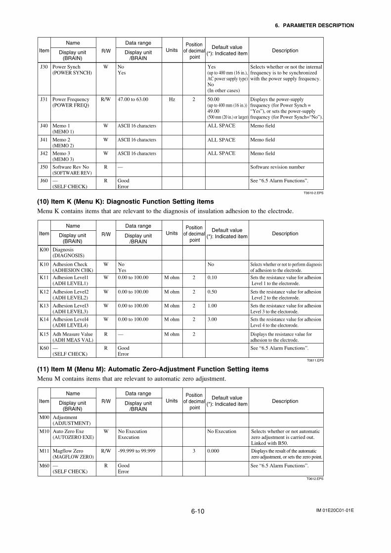
IM 01E20C01-01E6-10
6. PARAMETER DESCRIPTION
T0610-2.EPS
Item
Name
Display unit(BRAIN)
Data range
Display unit/BRAIN
Default value(*): Indicated item
UnitsR/WPosition
of decimal point
Description
J30 Power Synch(POWER SYNCH)
W NoYes
Yes (up to 400 mm (16 in.), AC power supply type)No(In other cases)
Selects whether or not the internal frequency is to be synchronized with the power supply frequency.
J40 Memo 1(MEMO 1)
W ASCII 16 characters Memo field
J41 Memo 2(MEMO 2)
W ASCII 16 characters Memo field
J42 Memo 3(MEMO 3)
W ASCII 16 characters Memo field
J50 Software Rev No(SOFTWARE REV)
R — Software revision number
J60 —(SELF CHECK)
R GoodError
See “6.5 Alarm Functions”.
J31 Power Frequency(POWER FREQ)
R/W Hz47.00 to 63.00 2 50.00 (up to 400 mm (16 in.))49.00 (500 mm (20 in.) or larger)
Displays the power-supply frequency (for Power Synch = “Yes”), or sets the power-supplyfrequency (for Power Synch=“No”).
ALL SPACE
ALL SPACE
ALL SPACE
(10) Item K (Menu K): Diagnostic Function Setting itemsMenu K contains items that are relevant to the diagnosis of insulation adhesion to the electrode.
T0611.EPS
Item
Name
Display unit(BRAIN)
Data range
Display unit/BRAIN
Default value(*): Indicated item
UnitsR/WPosition
of decimal point
Description
K60 —(SELF CHECK)
R GoodError
See “6.5 Alarm Functions”.
K00 Diagnosis(DIAGNOSIS)
K10 Adhesion Check(ADHESION CHK)
W NoYes
No Selects whether or not to perform diagnosis of adhesion to the electrode.
K11 Adhesion Level1(ADH LEVEL1)
W M ohm0.00 to 100.00 2 0.10 Sets the resistance value for adhesion Level 1 to the electorode.
K12 Adhesion Level2(ADH LEVEL2)
W M ohm0.00 to 100.00 2 0.50 Sets the resistance value for adhesion Level 2 to the electorode.
K13 Adhesion Level3(ADH LEVEL3)
W M ohm0.00 to 100.00 2 1.00 Sets the resistance value for adhesionLevel 3 to the electorode.
K14 Adhesion Level4(ADH LEVEL4)
W M ohm0.00 to 100.00 2 3.00 Sets the resistance value for adhesionLevel 4 to the electorode.
K15 Adh Measure Value(ADH MEAS VAL)
R M ohm— 2 Displays the resistance value for adhesion to the electrode.
(11) Item M (Menu M): Automatic Zero-Adjustment Function Setting itemsMenu M contains items that are relevant to automatic zero adjustment.
Item
Name
Display unit(BRAIN)
Data range
Display unit/BRAIN
Default value(*): Indicated item
UnitsR/WPosition
of decimal point
Description
T0612.EPS
M60 —(SELF CHECK)
R GoodError
See “6.5 Alarm Functions”.
M11 Magflow Zero(MAGFLOW ZERO)
M00 Adjustment(ADJUSTMENT)
R/W -99.999 to 99.999 3 0.000 Displays the result of the automatic zero adjustment, or sets the zero point.
M10 Auto Zero Exe(AUTOZERO EXE)
W No ExecutionExecution
No Execution Selects whether or not automatic zero adjustment is carried out. Linked with B50.
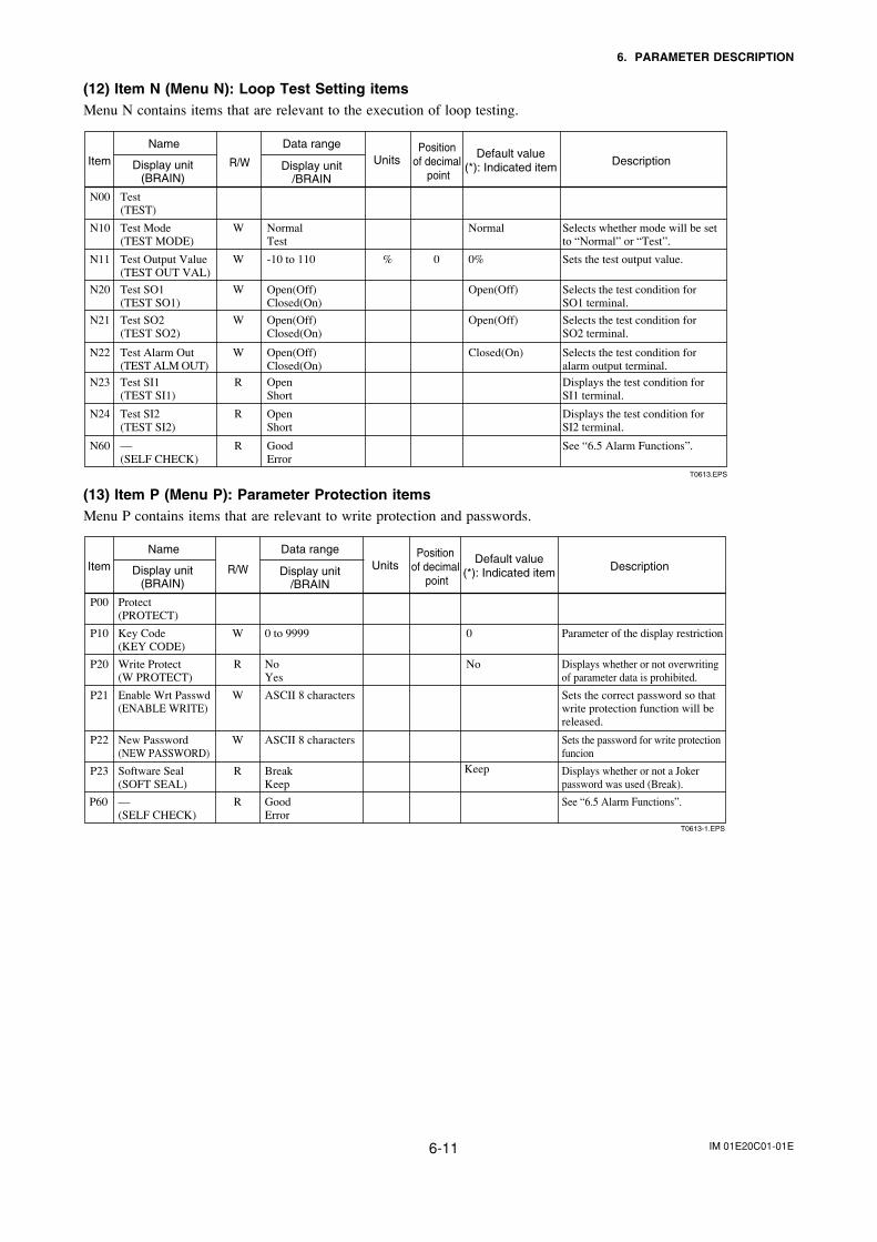
IM 01E20C01-01E6-11
6. PARAMETER DESCRIPTION
(12) Item N (Menu N): Loop Test Setting itemsMenu N contains items that are relevant to the execution of loop testing.
T0613.EPS
Item
Name
Display unit(BRAIN)
Data range
Display unit/BRAIN
Default value(*): Indicated item
UnitsR/WPosition
of decimal point
Description
N10 Test Mode(TEST MODE)
N00 Test(TEST)
W NormalTest
Normal Selects whether mode will be set to “Normal” or “Test”.
N20 Test SO1(TEST SO1)
W Open(Off)Closed(On)
Open(Off) Selects the test condition for SO1 terminal.
N21 Test SO2(TEST SO2)
W Open(Off)Closed(On)
Open(Off) Selects the test condition for SO2 terminal.
N22 Test Alarm Out(TEST ALM OUT)
W Open(Off)Closed(On)
Closed(On) Selects the test condition for alarm output terminal.
N23 Test SI1(TEST SI1)
R OpenShort
Displays the test condition for SI1 terminal.
N24 Test SI2(TEST SI2)
R OpenShort
Displays the test condition for SI2 terminal.
N60 —(SELF CHECK)
R GoodError
See “6.5 Alarm Functions”.
N11 Test Output Value(TEST OUT VAL)
W %-10 to 110 0 0% Sets the test output value.
(13) Item P (Menu P): Parameter Protection itemsMenu P contains items that are relevant to write protection and passwords.
T0613-1.EPS
Item
Name
Display unit(BRAIN)
Data range
Display unit/BRAIN
Default value(*): Indicated item
UnitsR/WPosition
of decimal point
Description
P10 Key Code(KEY CODE)
P00 Protect(PROTECT)
W 0 to 9999 0 Parameter of the display restriction
P20 Write Protect(W PROTECT)
R NoYes
No Displays whether or not overwriting of parameter data is prohibited.
P21 Enable Wrt Passwd(ENABLE WRITE)
W ASCII 8 characters Sets the correct password so that write protection function will be released.
P22 New Password(NEW PASSWORD)
W ASCII 8 characters Sets the password for write protectionfuncion
P23 Software Seal(SOFT SEAL)
R BreakKeep
Displays whether or not a Joker password was used (Break).
P60 —(SELF CHECK)
R GoodError
See “6.5 Alarm Functions”.
Keep
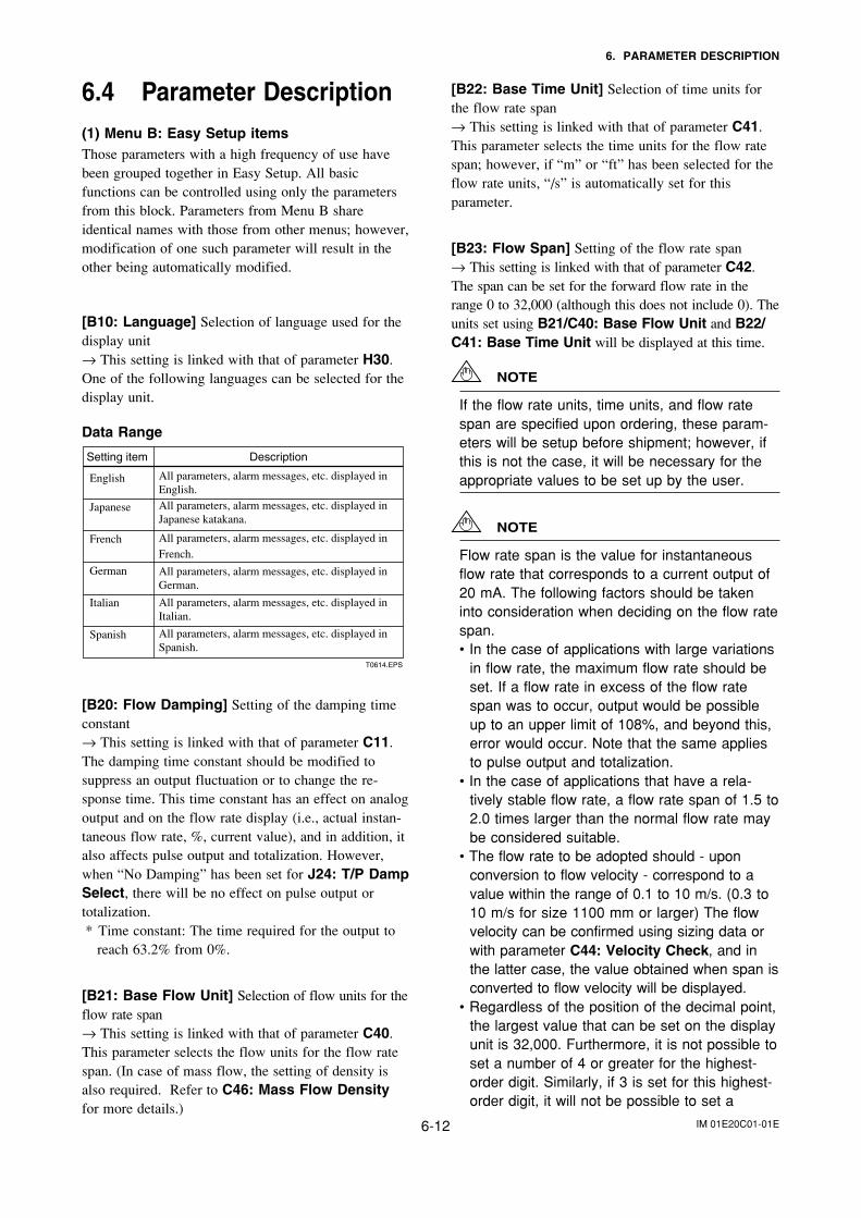
IM 01E20C01-01E6-12
6. PARAMETER DESCRIPTION
6.4 Parameter Description(1) Menu B: Easy Setup itemsThose parameters with a high frequency of use havebeen grouped together in Easy Setup. All basicfunctions can be controlled using only the parametersfrom this block. Parameters from Menu B shareidentical names with those from other menus; however,modification of one such parameter will result in theother being automatically modified.
[B10: Language] Selection of language used for thedisplay unit→ This setting is linked with that of parameter H30.One of the following languages can be selected for thedisplay unit.
Data Range
Setting item Description
English
Japanese
French
German
Italian
Spanish
T0614.EPS
All parameters, alarm messages, etc. displayed in English.All parameters, alarm messages, etc. displayed in Japanese katakana.
All parameters, alarm messages, etc. displayed inFrench.
All parameters, alarm messages, etc. displayed in German.
All parameters, alarm messages, etc. displayed in Italian.
All parameters, alarm messages, etc. displayed in Spanish.
[B20: Flow Damping] Setting of the damping timeconstant→ This setting is linked with that of parameter C11.The damping time constant should be modified tosuppress an output fluctuation or to change the re-sponse time. This time constant has an effect on analogoutput and on the flow rate display (i.e., actual instan-taneous flow rate, %, current value), and in addition, italso affects pulse output and totalization. However,when “No Damping” has been set for J24: T/P DampSelect, there will be no effect on pulse output ortotalization. * Time constant: The time required for the output to
reach 63.2% from 0%.
[B21: Base Flow Unit] Selection of flow units for theflow rate span→ This setting is linked with that of parameter C40.This parameter selects the flow units for the flow ratespan. (In case of mass flow, the setting of density isalso required. Refer to C46: Mass Flow Densityfor more details.)
[B22: Base Time Unit] Selection of time units forthe flow rate span→ This setting is linked with that of parameter C41.This parameter selects the time units for the flow ratespan; however, if “m” or “ft” has been selected for theflow rate units, “/s” is automatically set for thisparameter.
[B23: Flow Span] Setting of the flow rate span→ This setting is linked with that of parameter C42.The span can be set for the forward flow rate in therange 0 to 32,000 (although this does not include 0). Theunits set using B21/C40: Base Flow Unit and B22/C41: Base Time Unit will be displayed at this time.
NOTE
If the flow rate units, time units, and flow ratespan are specified upon ordering, these param-eters will be setup before shipment; however, ifthis is not the case, it will be necessary for theappropriate values to be set up by the user.
NOTE
Flow rate span is the value for instantaneousflow rate that corresponds to a current output of20 mA. The following factors should be takeninto consideration when deciding on the flow ratespan.• In the case of applications with large variations
in flow rate, the maximum flow rate should beset. If a flow rate in excess of the flow ratespan was to occur, output would be possibleup to an upper limit of 108%, and beyond this,error would occur. Note that the same appliesto pulse output and totalization.
• In the case of applications that have a rela-tively stable flow rate, a flow rate span of 1.5 to2.0 times larger than the normal flow rate maybe considered suitable.
• The flow rate to be adopted should - uponconversion to flow velocity - correspond to avalue within the range of 0.1 to 10 m/s. (0.3 to10 m/s for size 1100 mm or larger) The flowvelocity can be confirmed using sizing data orwith parameter C44: Velocity Check, and inthe latter case, the value obtained when span isconverted to flow velocity will be displayed.
• Regardless of the position of the decimal point,the largest value that can be set on the displayunit is 32,000. Furthermore, it is not possible toset a number of 4 or greater for the highest-order digit. Similarly, if 3 is set for this highest-order digit, it will not be possible to set a
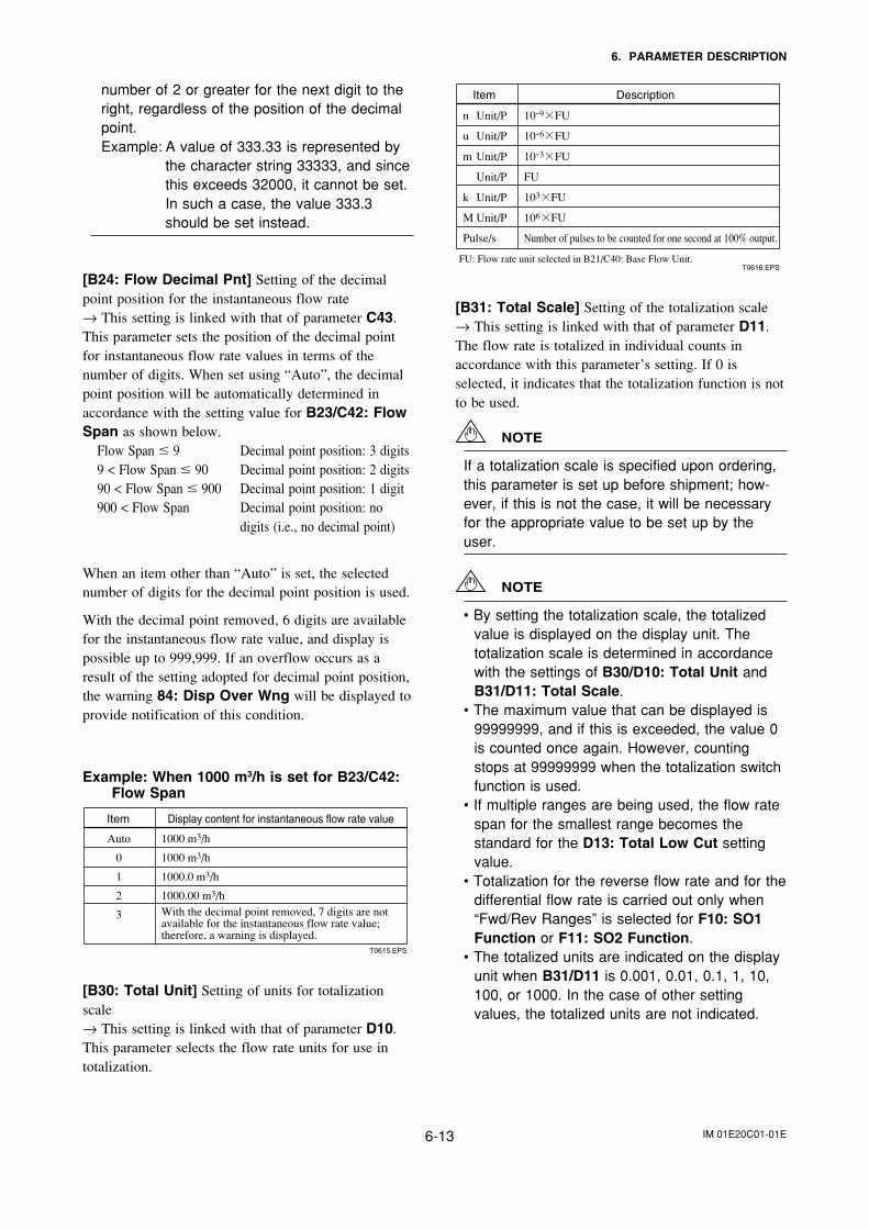
IM 01E20C01-01E6-13
6. PARAMETER DESCRIPTION
number of 2 or greater for the next digit to theright, regardless of the position of the decimalpoint.Example: A value of 333.33 is represented by
the character string 33333, and sincethis exceeds 32000, it cannot be set.In such a case, the value 333.3should be set instead.
[B24: Flow Decimal Pnt] Setting of the decimalpoint position for the instantaneous flow rate→ This setting is linked with that of parameter C43.This parameter sets the position of the decimal pointfor instantaneous flow rate values in terms of thenumber of digits. When set using “Auto”, the decimalpoint position will be automatically determined inaccordance with the setting value for B23/C42: FlowSpan as shown below.
Flow Span 9 Decimal point position: 3 digits9 < Flow Span 90 Decimal point position: 2 digits90 < Flow Span 900 Decimal point position: 1 digit900 < Flow Span Decimal point position: no
digits (i.e., no decimal point)
When an item other than “Auto” is set, the selectednumber of digits for the decimal point position is used.
With the decimal point removed, 6 digits are availablefor the instantaneous flow rate value, and display ispossible up to 999,999. If an overflow occurs as aresult of the setting adopted for decimal point position,the warning 84: Disp Over Wng will be displayed toprovide notification of this condition.
Example: When 1000 m3/h is set for B23/C42:Flow Span
Item Display content for instantaneous flow rate value
Auto
0
1
2
3
1000 m3/h
1000 m3/h
1000.0 m3/h
1000.00 m3/hWith the decimal point removed, 7 digits are not available for the instantaneous flow rate value; therefore, a warning is displayed.
T0615.EPS
[B30: Total Unit] Setting of units for totalizationscale→ This setting is linked with that of parameter D10.This parameter selects the flow rate units for use intotalization.
Item Description
n Unit/P
u Unit/P
m Unit/P
Unit/P
k Unit/P
M Unit/P
Pulse/s
10-9 FU
10-6 FU
10-3 FU
FU
103 FU
106 FU
Number of pulses to be counted for one second at 100% output.
T0616.EPSFU: Flow rate unit selected in B21/C40: Base Flow Unit.
[B31: Total Scale] Setting of the totalization scale→ This setting is linked with that of parameter D11.The flow rate is totalized in individual counts inaccordance with this parameter’s setting. If 0 isselected, it indicates that the totalization function is notto be used.
NOTE
If a totalization scale is specified upon ordering,this parameter is set up before shipment; how-ever, if this is not the case, it will be necessaryfor the appropriate value to be set up by theuser.
NOTE
• By setting the totalization scale, the totalizedvalue is displayed on the display unit. Thetotalization scale is determined in accordancewith the settings of B30/D10: Total Unit andB31/D11: Total Scale.
• The maximum value that can be displayed is99999999, and if this is exceeded, the value 0is counted once again. However, countingstops at 99999999 when the totalization switchfunction is used.
• If multiple ranges are being used, the flow ratespan for the smallest range becomes thestandard for the D13: Total Low Cut settingvalue.
• Totalization for the reverse flow rate and for thedifferential flow rate is carried out only when“Fwd/Rev Ranges” is selected for F10: SO1Function or F11: SO2 Function.
• The totalized units are indicated on the displayunit when B31/D11 is 0.001, 0.01, 0.1, 1, 10,100, or 1000. In the case of other settingvalues, the totalized units are not indicated.
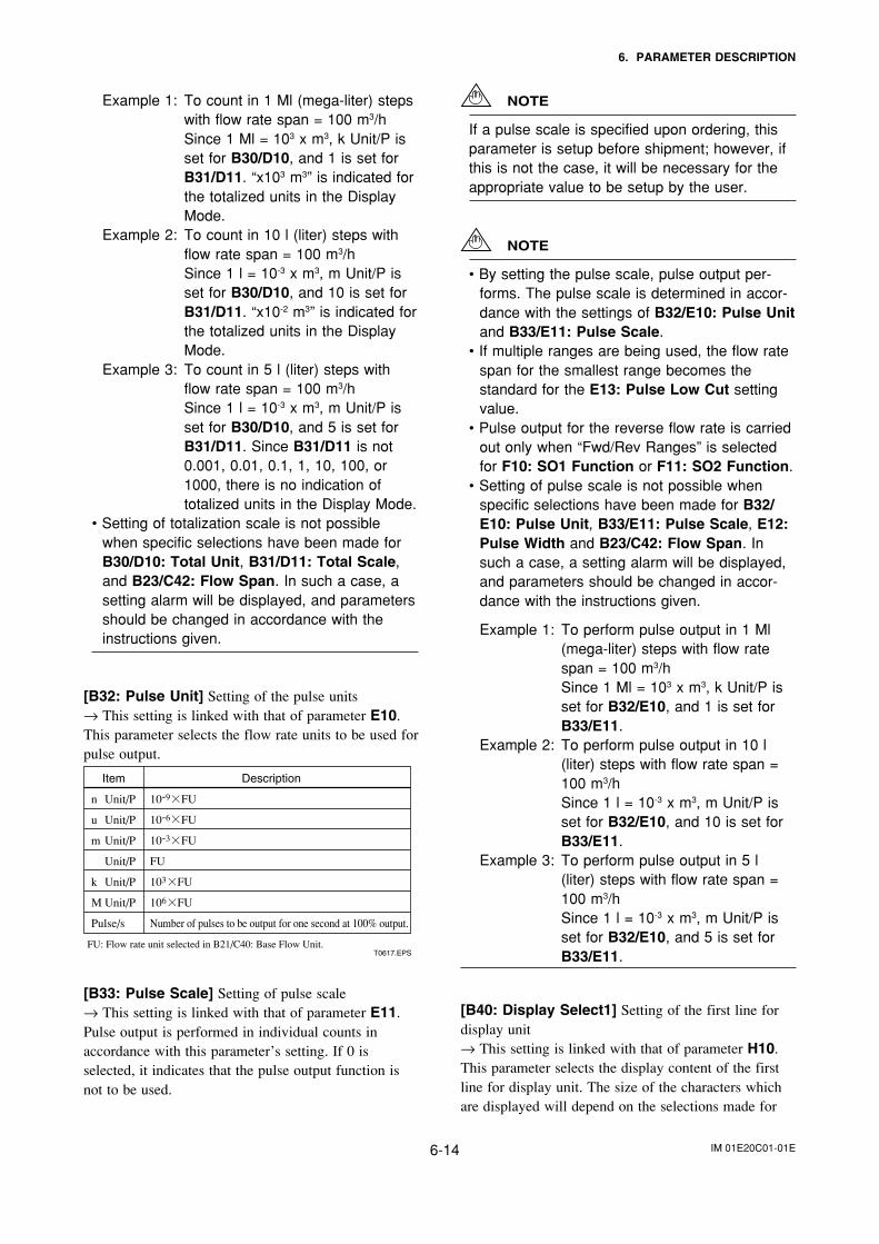
IM 01E20C01-01E6-14
6. PARAMETER DESCRIPTION
Example 1: To count in 1 Ml (mega-liter) stepswith flow rate span = 100 m3/hSince 1 Ml = 103 x m3, k Unit/P isset for B30/D10, and 1 is set forB31/D11. “x103 m3” is indicated forthe totalized units in the DisplayMode.
Example 2: To count in 10 l (liter) steps withflow rate span = 100 m3/hSince 1 l = 10-3 x m3, m Unit/P isset for B30/D10, and 10 is set forB31/D11. “x10-2 m3” is indicated forthe totalized units in the DisplayMode.
Example 3: To count in 5 l (liter) steps withflow rate span = 100 m3/hSince 1 l = 10-3 x m3, m Unit/P isset for B30/D10, and 5 is set forB31/D11. Since B31/D11 is not0.001, 0.01, 0.1, 1, 10, 100, or1000, there is no indication oftotalized units in the Display Mode.
• Setting of totalization scale is not possiblewhen specific selections have been made forB30/D10: Total Unit, B31/D11: Total Scale,and B23/C42: Flow Span. In such a case, asetting alarm will be displayed, and parametersshould be changed in accordance with theinstructions given.
[B32: Pulse Unit] Setting of the pulse units→ This setting is linked with that of parameter E10.This parameter selects the flow rate units to be used forpulse output.
Item Description
n Unit/P
u Unit/P
m Unit/P
Unit/P
k Unit/P
M Unit/P
Pulse/s
10-9 FU
10-6 FU
10-3 FU
FU
103 FU
106 FU
Number of pulses to be output for one second at 100% output.
T0617.EPSFU: Flow rate unit selected in B21/C40: Base Flow Unit.
[B33: Pulse Scale] Setting of pulse scale→ This setting is linked with that of parameter E11.Pulse output is performed in individual counts inaccordance with this parameter’s setting. If 0 isselected, it indicates that the pulse output function isnot to be used.
NOTE
If a pulse scale is specified upon ordering, thisparameter is setup before shipment; however, ifthis is not the case, it will be necessary for theappropriate value to be setup by the user.
NOTE
• By setting the pulse scale, pulse output per-forms. The pulse scale is determined in accor-dance with the settings of B32/E10: Pulse Unitand B33/E11: Pulse Scale.
• If multiple ranges are being used, the flow ratespan for the smallest range becomes thestandard for the E13: Pulse Low Cut settingvalue.
• Pulse output for the reverse flow rate is carriedout only when “Fwd/Rev Ranges” is selectedfor F10: SO1 Function or F11: SO2 Function.
• Setting of pulse scale is not possible whenspecific selections have been made for B32/E10: Pulse Unit, B33/E11: Pulse Scale, E12:Pulse Width and B23/C42: Flow Span. Insuch a case, a setting alarm will be displayed,and parameters should be changed in accor-dance with the instructions given.
Example 1: To perform pulse output in 1 Ml(mega-liter) steps with flow ratespan = 100 m3/hSince 1 Ml = 103 x m3, k Unit/P isset for B32/E10, and 1 is set forB33/E11.
Example 2: To perform pulse output in 10 l(liter) steps with flow rate span =100 m3/hSince 1 l = 10-3 x m3, m Unit/P isset for B32/E10, and 10 is set forB33/E11.
Example 3: To perform pulse output in 5 l(liter) steps with flow rate span =100 m3/hSince 1 l = 10-3 x m3, m Unit/P isset for B32/E10, and 5 is set forB33/E11.
[B40: Display Select1] Setting of the first line fordisplay unit→ This setting is linked with that of parameter H10.This parameter selects the display content of the firstline for display unit. The size of the characters whichare displayed will depend on the selections made for
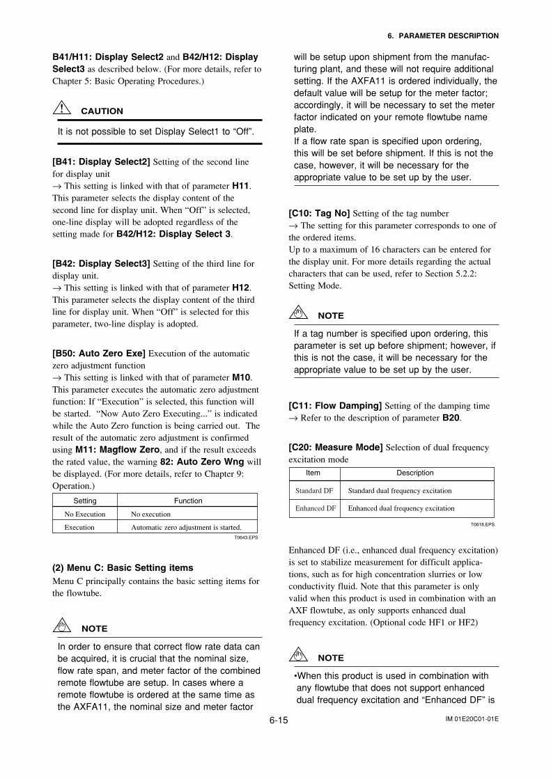
IM 01E20C01-01E6-15
6. PARAMETER DESCRIPTION
B41/H11: Display Select2 and B42/H12: DisplaySelect3 as described below. (For more details, refer toChapter 5: Basic Operating Procedures.)
CAUTION
It is not possible to set Display Select1 to “Off”.
[B41: Display Select2] Setting of the second linefor display unit→ This setting is linked with that of parameter H11.This parameter selects the display content of thesecond line for display unit. When “Off” is selected,one-line display will be adopted regardless of thesetting made for B42/H12: Display Select 3.
[B42: Display Select3] Setting of the third line fordisplay unit.→ This setting is linked with that of parameter H12.This parameter selects the display content of the thirdline for display unit. When “Off” is selected for thisparameter, two-line display is adopted.
[B50: Auto Zero Exe] Execution of the automaticzero adjustment function→ This setting is linked with that of parameter M10.This parameter executes the automatic zero adjustmentfunction: If “Execution” is selected, this function willbe started. “Now Auto Zero Executing...” is indicatedwhile the Auto Zero function is being carried out. Theresult of the automatic zero adjustment is confirmedusing M11: Magflow Zero, and if the result exceedsthe rated value, the warning 82: Auto Zero Wng willbe displayed. (For more details, refer to Chapter 9:Operation.)
Setting Function
No execution
Automatic zero adjustment is started.
No Execution
ExecutionT0643.EPS
(2) Menu C: Basic Setting itemsMenu C principally contains the basic setting items forthe flowtube.
NOTE
In order to ensure that correct flow rate data canbe acquired, it is crucial that the nominal size,flow rate span, and meter factor of the combinedremote flowtube are setup. In cases where aremote flowtube is ordered at the same time asthe AXFA11, the nominal size and meter factor
will be setup upon shipment from the manufac-turing plant, and these will not require additionalsetting. If the AXFA11 is ordered individually, thedefault value will be setup for the meter factor;accordingly, it will be necessary to set the meterfactor indicated on your remote flowtube nameplate.If a flow rate span is specified upon ordering,this will be set before shipment. If this is not thecase, however, it will be necessary for theappropriate value to be set up by the user.
[C10: Tag No] Setting of the tag number→ The setting for this parameter corresponds to one ofthe ordered items.Up to a maximum of 16 characters can be entered forthe display unit. For more details regarding the actualcharacters that can be used, refer to Section 5.2.2:Setting Mode.
NOTE
If a tag number is specified upon ordering, thisparameter is set up before shipment; however, ifthis is not the case, it will be necessary for theappropriate value to be set up by the user.
[C11: Flow Damping] Setting of the damping time→ Refer to the description of parameter B20.
[C20: Measure Mode] Selection of dual frequencyexcitation mode
Item Description
T0618.EPS
Standard DF Standard dual frequency excitation
Enhanced DF Enhanced dual frequency excitation
Enhanced DF (i.e., enhanced dual frequency excitation)is set to stabilize measurement for difficult applica-tions, such as for high concentration slurries or lowconductivity fluid. Note that this parameter is onlyvalid when this product is used in combination with anAXF flowtube, as only supports enhanced dualfrequency excitation. (Optional code HF1 or HF2)
NOTE
•When this product is used in combination withany flowtube that does not support enhanceddual frequency excitation and “Enhanced DF” is
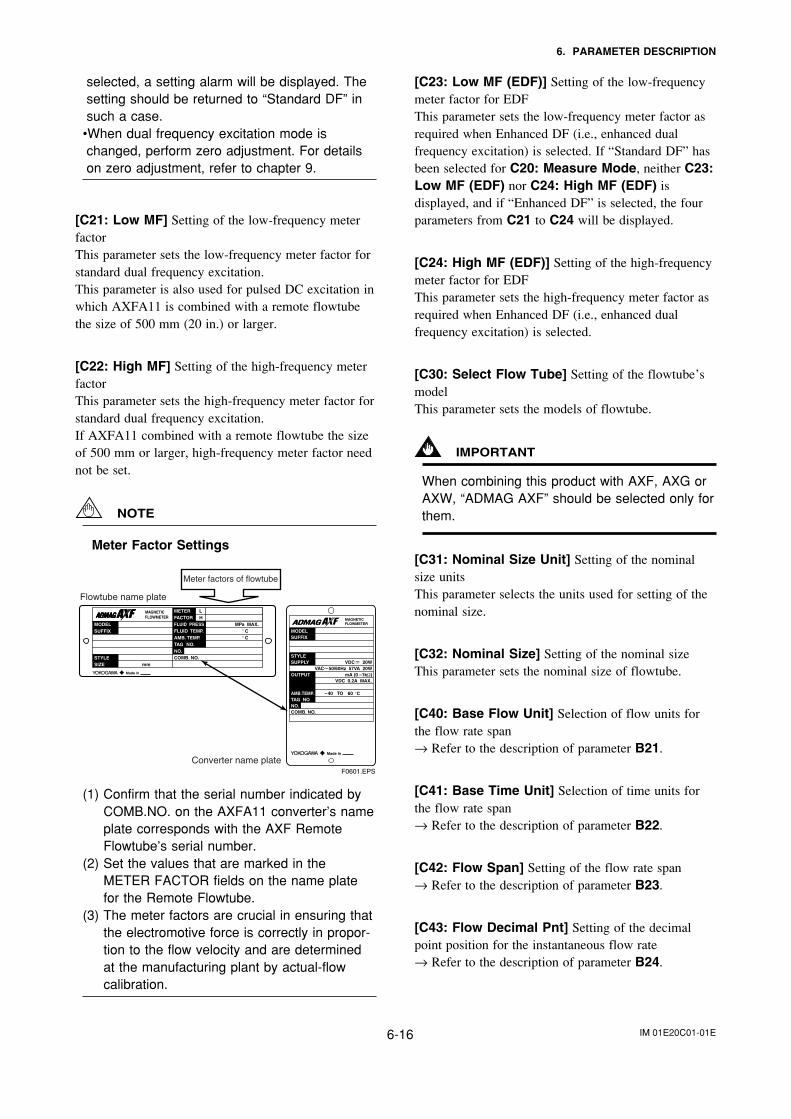
IM 01E20C01-01E6-16
6. PARAMETER DESCRIPTION
selected, a setting alarm will be displayed. Thesetting should be returned to “Standard DF” insuch a case.
•When dual frequency excitation mode ischanged, perform zero adjustment. For detailson zero adjustment, refer to chapter 9.
[C21: Low MF] Setting of the low-frequency meterfactorThis parameter sets the low-frequency meter factor forstandard dual frequency excitation.This parameter is also used for pulsed DC excitation inwhich AXFA11 is combined with a remote flowtubethe size of 500 mm (20 in.) or larger.
[C22: High MF] Setting of the high-frequency meterfactorThis parameter sets the high-frequency meter factor forstandard dual frequency excitation.If AXFA11 combined with a remote flowtube the sizeof 500 mm or larger, high-frequency meter factor neednot be set.
NOTE
Meter Factor Settings
Meter factors of flowtube
Flowtube name plate
Converter name plateF0601.EPS
(1) Confirm that the serial number indicated byCOMB.NO. on the AXFA11 converter’s nameplate corresponds with the AXF RemoteFlowtube’s serial number.
(2) Set the values that are marked in theMETER FACTOR fields on the name platefor the Remote Flowtube.
(3) The meter factors are crucial in ensuring thatthe electromotive force is correctly in propor-tion to the flow velocity and are determinedat the manufacturing plant by actual-flowcalibration.
[C23: Low MF (EDF)] Setting of the low-frequencymeter factor for EDFThis parameter sets the low-frequency meter factor asrequired when Enhanced DF (i.e., enhanced dualfrequency excitation) is selected. If “Standard DF” hasbeen selected for C20: Measure Mode, neither C23:Low MF (EDF) nor C24: High MF (EDF) isdisplayed, and if “Enhanced DF” is selected, the fourparameters from C21 to C24 will be displayed.
[C24: High MF (EDF)] Setting of the high-frequencymeter factor for EDFThis parameter sets the high-frequency meter factor asrequired when Enhanced DF (i.e., enhanced dualfrequency excitation) is selected.
[C30: Select Flow Tube] Setting of the flowtube’smodelThis parameter sets the models of flowtube.
IMPORTANT
When combining this product with AXF, AXG orAXW, “ADMAG AXF” should be selected only forthem.
[C31: Nominal Size Unit] Setting of the nominalsize unitsThis parameter selects the units used for setting of thenominal size.
[C32: Nominal Size] Setting of the nominal sizeThis parameter sets the nominal size of flowtube.
[C40: Base Flow Unit] Selection of flow units forthe flow rate span→ Refer to the description of parameter B21.
[C41: Base Time Unit] Selection of time units forthe flow rate span→ Refer to the description of parameter B22.
[C42: Flow Span] Setting of the flow rate span→ Refer to the description of parameter B23.
[C43: Flow Decimal Pnt] Setting of the decimalpoint position for the instantaneous flow rate→ Refer to the description of parameter B24.
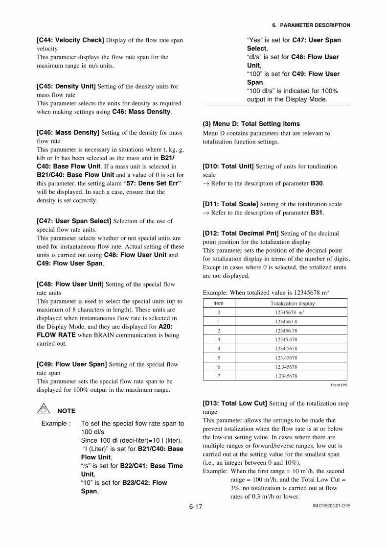
IM 01E20C01-01E6-17
6. PARAMETER DESCRIPTION
[C44: Velocity Check] Display of the flow rate spanvelocityThis parameter displays the flow rate span for themaximum range in m/s units.
[C45: Density Unit] Setting of the density units formass flow rateThis parameter selects the units for density as requiredwhen making settings using C46: Mass Density.
[C46: Mass Density] Setting of the density for massflow rateThis parameter is necessary in situations where t, kg, g,klb or lb has been selected as the mass unit in B21/C40: Base Flow Unit. If a mass unit is selected inB21/C40: Base Flow Unit and a value of 0 is set forthis parameter, the setting alarm “57: Dens Set Err”will be displayed. In such a case, ensure that thedensity is set correctly.
[C47: User Span Select] Selection of the use ofspecial flow rate units.This parameter selects whether or not special units areused for instantaneous flow rate. Actual setting of theseunits is carried out using C48: Flow User Unit andC49: Flow User Span.
[C48: Flow User Unit] Setting of the special flowrate unitsThis parameter is used to select the special units (up tomaximum of 8 characters in length). These units aredisplayed when instantaneous flow rate is selected inthe Display Mode, and they are displayed for A20:FLOW RATE when BRAIN communication is beingcarried out.
[C49: Flow User Span] Setting of the special flowrate spanThis parameter sets the special flow rate span to bedisplayed for 100% output in the maximum range.
NOTE
Example : To set the special flow rate span to100 dl/sSince 100 dl (deci-liter)=10 l (liter), “l (Liter)” is set for B21/C40: BaseFlow Unit,“/s” is set for B22/C41: Base TimeUnit,“10” is set for B23/C42: FlowSpan,
“Yes” is set for C47: User SpanSelect,“dl/s” is set for C48: Flow UserUnit,“100” is set for C49: Flow UserSpan.“100 dl/s” is indicated for 100%output in the Display Mode.
(3) Menu D: Total Setting itemsMenu D contains parameters that are relevant tototalization function settings.
[D10: Total Unit] Setting of units for totalizationscale→ Refer to the description of parameter B30.
[D11: Total Scale] Setting of the totalization scale→ Refer to the description of parameter B31.
[D12: Total Decimal Pnt] Setting of the decimalpoint position for the totalization displayThis parameter sets the position of the decimal pointfor totalization display in terms of the number of digits.Except in cases where 0 is selected, the totalized unitsare not displayed.
Example: When totalized value is 12345678 m3
T0619.EPS
Item Totalization display
0
1
2
3
4
5
6
7
12345678 m3
1234567.8
123456.78
12345.678
1234.5678
123.45678
12.345678
1.2345678
[D13: Total Low Cut] Setting of the totalization stoprangeThis parameter allows the settings to be made thatprevent totalization when the flow rate is at or belowthe low-cut setting value. In cases where there aremultiple ranges or forward/reverse ranges, low cut iscarried out at the setting value for the smallest span(i.e., an integer between 0 and 10%).Example: When the first range = 10 m3/h, the second
range = 100 m3/h, and the Total Low Cut =3%, no totalization is carried out at flowrates of 0.3 m3/h or lower.
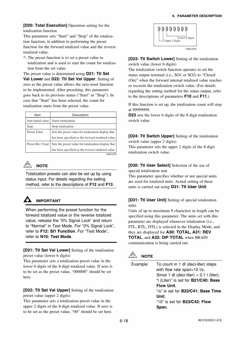
IM 01E20C01-01E6-18
6. PARAMETER DESCRIPTION
[D20: Total Execution] Operation setting for thetotalization functionThis parameter sets “Start” and “Stop” of the totaliza-tion function, in addition to performing the presetfunction for the forward totalized value and the reversetotalized value.*: The preset function is to set a preset value to
totalization and is used to start the count for totaliza-tion from the set value.
The preset value is determined using D21: Ttl SetVal Lower and D22: Ttl Set Val Upper. Setting ofzero as the preset value allows the zero-reset functionto be implemented. After presetting, this parametergoes back to its previous status (“Start” or “Stop”). Incase that “Start” has been selected, the count fortotalization starts from the preset value.
Item Description
T0620.EPS
Start (initial value)
Stop
Preset Total
Preset Rev Total
Starts totalization
Stop totalization
Sets the preset value for totalization display that
has been specified as the forward totalized value.
Sets the preset value for totalization display that
has been specified as the reverse totalized value.
NOTE
Totalization presets can also be set up by usingstatus input. For details regarding the settingmethod, refer to the descriptions of F12 and F13.
IMPORTANT
When performing the preset function for theforward totalized value or the reverse totalizedvalue, release the “0% Signal Lock” and returnto “Normal” in Test Mode. For “0% Signal Lock”,refer to F12: SI1 Function. For “Test Mode”,refer to N10: Test Mode.
[D21: Ttl Set Val Lower] Setting of the totalizationpreset value (lower 6 digits)This parameter sets a totalization preset value in thelower 6 digits of the 8-digit totalized value. If zero isto be set as the preset value, “000000” should be sethere.
[D22: Ttl Set Val Upper] Setting of the totalizationpreset value (upper 2 digits)This parameter sets a totalization preset value in theupper 2 digits of the 8-digit totalized value. If zero isto be set as the preset value, “00” should be set here.
F0602.EPS
Upper 2 digitsLower 6 digits
[D23: Ttl Switch Lower] Setting of the totalizationswitch value (lower 6 digits)The totalization switch function operates to set thestatus output terminal (i.e., SO1 or SO2) to “Closed(On)” when the forward internal totalized value reachesor exceeds the totalization switch value. (For detailsregarding the setting method for the status output, referto the descriptions of parameters F10 and F11.)
If this function is set up, the totalization count will stopat 99999999.D23 sets the lower 6 digits of the 8-digit totalizationswitch value.
[D24: Ttl Switch Upper] Setting of the totalizationswitch value (upper 2 digits)This parameter sets the upper 2 digits of the 8-digittotalization switch value.
[D30: Ttl User Select] Selection of the use ofspecial totalization unitThis parameter specifies whether or not special unitsare used for totalized units. Actual setting of theseunits is carried out using D31: Ttl User Unit.
[D31: Ttl User Unit] Setting of special totalizationunitsUnits of up to maximum 8 characters in length can bespecified using this parameter. The units set with thisparameter are displayed whenever totalization (i.e.,FTL, RTL, DTL) is selected in the Display Mode, andthey are displayed for A30: TOTAL, A31: REVTOTAL, and A32: DIF TOTAL when BRAINcommunication is being carried out.
NOTE
Example: To count in 1 dl (deci-liter) stepswith flow rate span=10 l/s.Since 1 dl (deci-liter) = 0.1 l (liter),“l (Liter)” is set for B21/C40: BaseFlow Unit,“/s” is set for B22/C41: Base TimeUnit,“10” is set for B23/C42: FlowSpan,
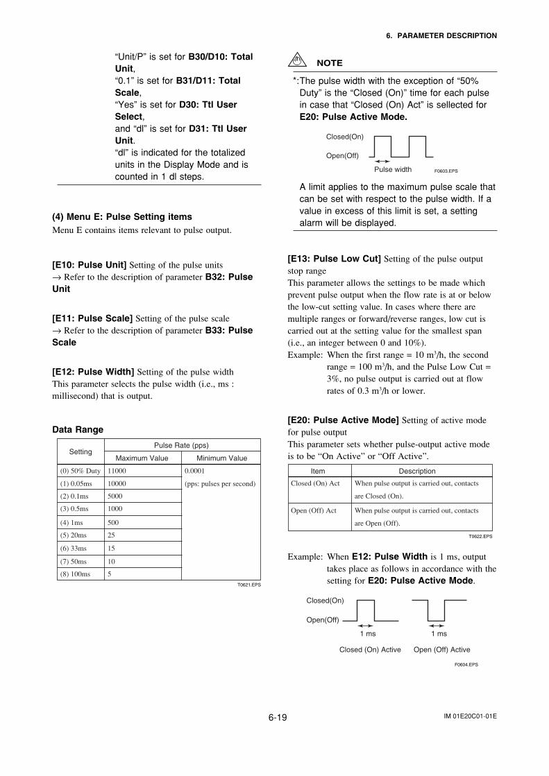
IM 01E20C01-01E6-19
6. PARAMETER DESCRIPTION
“Unit/P” is set for B30/D10: TotalUnit,“0.1” is set for B31/D11: TotalScale,“Yes” is set for D30: Ttl UserSelect,and “dl” is set for D31: Ttl UserUnit.“dl” is indicated for the totalizedunits in the Display Mode and iscounted in 1 dl steps.
(4) Menu E: Pulse Setting itemsMenu E contains items relevant to pulse output.
[E10: Pulse Unit] Setting of the pulse units→ Refer to the description of parameter B32: PulseUnit
[E11: Pulse Scale] Setting of the pulse scale→ Refer to the description of parameter B33: PulseScale
[E12: Pulse Width] Setting of the pulse widthThis parameter selects the pulse width (i.e., ms :millisecond) that is output.
Data Range
T0621.EPS
SettingPulse Rate (pps)
Maximum Value Minimum Value
(1) 0.05ms
(2) 0.1ms
(3) 0.5ms
(4) 1ms
(5) 20ms
(6) 33ms
(7) 50ms
(8) 100ms
(0) 50% Duty
10000
5000
1000
500
25
15
10
5
11000 0.0001
(pps: pulses per second)
NOTE
*:The pulse width with the exception of “50%Duty” is the “Closed (On)” time for each pulsein case that “Closed (On) Act” is sellected forE20: Pulse Active Mode.
F0603.EPSPulse width
Closed(On)
Open(Off)
A limit applies to the maximum pulse scale thatcan be set with respect to the pulse width. If avalue in excess of this limit is set, a settingalarm will be displayed.
[E13: Pulse Low Cut] Setting of the pulse outputstop rangeThis parameter allows the settings to be made whichprevent pulse output when the flow rate is at or belowthe low-cut setting value. In cases where there aremultiple ranges or forward/reverse ranges, low cut iscarried out at the setting value for the smallest span(i.e., an integer between 0 and 10%).Example: When the first range = 10 m3/h, the second
range = 100 m3/h, and the Pulse Low Cut =3%, no pulse output is carried out at flowrates of 0.3 m3/h or lower.
[E20: Pulse Active Mode] Setting of active modefor pulse outputThis parameter sets whether pulse-output active modeis to be “On Active” or “Off Active”.
Item Description
T0622.EPS
Open (Off) Act
Closed (On) Act
When pulse output is carried out, contacts
are Open (Off).
When pulse output is carried out, contacts
are Closed (On).
Example: When E12: Pulse Width is 1 ms, outputtakes place as follows in accordance with thesetting for E20: Pulse Active Mode.
F0604.EPS
1 ms 1 ms
Closed (On) Active Open (Off) Active
Closed(On)
Open(Off)
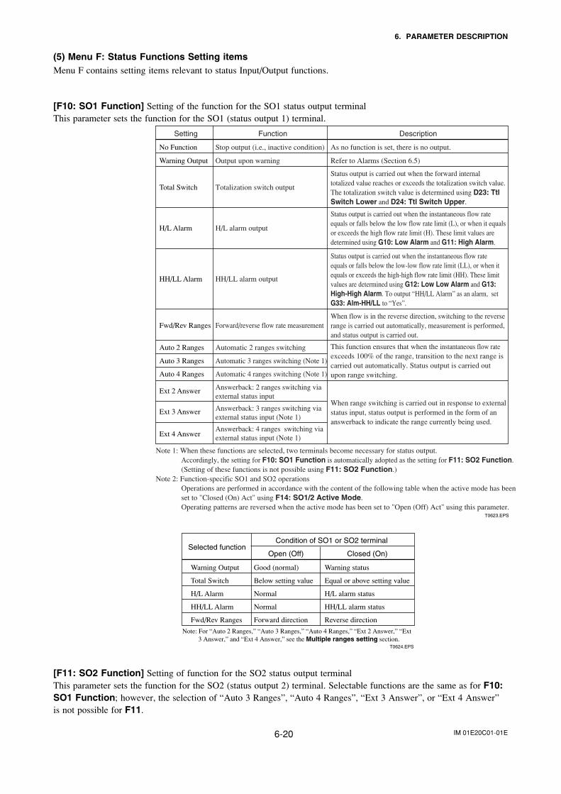
IM 01E20C01-01E6-20
6. PARAMETER DESCRIPTION
(5) Menu F: Status Functions Setting itemsMenu F contains setting items relevant to status Input/Output functions.
[F10: SO1 Function] Setting of the function for the SO1 status output terminalThis parameter sets the function for the SO1 (status output 1) terminal.
Setting
No Function Stop output (i.e., inactive condition) As no function is set, there is no output.
Warning Output Output upon warning
Total Switch Totalization switch output
Refer to Alarms (Section 6.5)
Status output is carried out when the forward internal totalized value reaches or exceeds the totalization switch value. The totalization switch value is determined using D23: Ttl Switch Lower and D24: Ttl Switch Upper.
H/L Alarm H/L alarm output
Status output is carried out when the instantaneous flow rate equals or falls below the low flow rate limit (L), or when it equals or exceeds the high flow rate limit (H). These limit values are determined using G10: Low Alarm and G11: High Alarm.
HH/LL Alarm HH/LL alarm output
Fwd/Rev Ranges Forward/reverse flow rate measurement
Auto 2 Ranges Automatic 2 ranges switching
Auto 3 Ranges Automatic 3 ranges switching (Note 1)
Auto 4 Ranges
Ext 2 Answer
Ext 3 Answer
Ext 4 Answer
Automatic 4 ranges switching (Note 1)
Answerback: 2 ranges switching via external status input
Answerback: 3 ranges switching via external status input (Note 1)
Answerback: 4 ranges switching via external status input (Note 1)
Status output is carried out when the instantaneous flow rate equals or falls below the low-low flow rate limit (LL), or when it equals or exceeds the high-high flow rate limit (HH). These limit values are determined using G12: Low Low Alarm and G13: High-High Alarm. To output “HH/LL Alarm” as an alarm, set G33: Alm-HH/LL to “Yes”.
When flow is in the reverse direction, switching to the reverse range is carried out automatically, measurement is performed, and status output is carried out.
This function ensures that when the instantaneous flow rate exceeds 100% of the range, transition to the next range is carried out automatically. Status output is carried out upon range switching.
When range switching is carried out in response to external status input, status output is performed in the form of an answerback to indicate the range currently being used.
DescriptionFunction
T0623.EPS
Note 1: When these functions are selected, two terminals become necessary for status output. Accordingly, the setting for F10: SO1 Function is automatically adopted as the setting for F11: SO2 Function. (Setting of these functions is not possible using F11: SO2 Function.)
Note 2: Function-specific SO1 and SO2 operationsOperations are performed in accordance with the content of the following table when the active mode has beenset to "Closed (On) Act" using F14: SO1/2 Active Mode. Operating patterns are reversed when the active mode has been set to "Open (Off) Act" using this parameter.
Selected functionCondition of SO1 or SO2 terminal
Closed (On)Open (Off)
Warning status
Equal or above setting value
H/L alarm status
HH/LL alarm status
Reverse direction
Good (normal)
Below setting value
Normal
Normal
Forward direction
Warning Output
Total Switch
H/L Alarm
HH/LL Alarm
Fwd/Rev Ranges
T0624.EPS
Note: For “Auto 2 Ranges,” “Auto 3 Ranges,” “Auto 4 Ranges,” “Ext 2 Answer,” “Ext 3 Answer,” and “Ext 4 Answer,” see the Multiple ranges setting section.
[F11: SO2 Function] Setting of function for the SO2 status output terminalThis parameter sets the function for the SO2 (status output 2) terminal. Selectable functions are the same as for F10:SO1 Function; however, the selection of “Auto 3 Ranges”, “Auto 4 Ranges”, “Ext 3 Answer”, or “Ext 4 Answer”is not possible for F11.
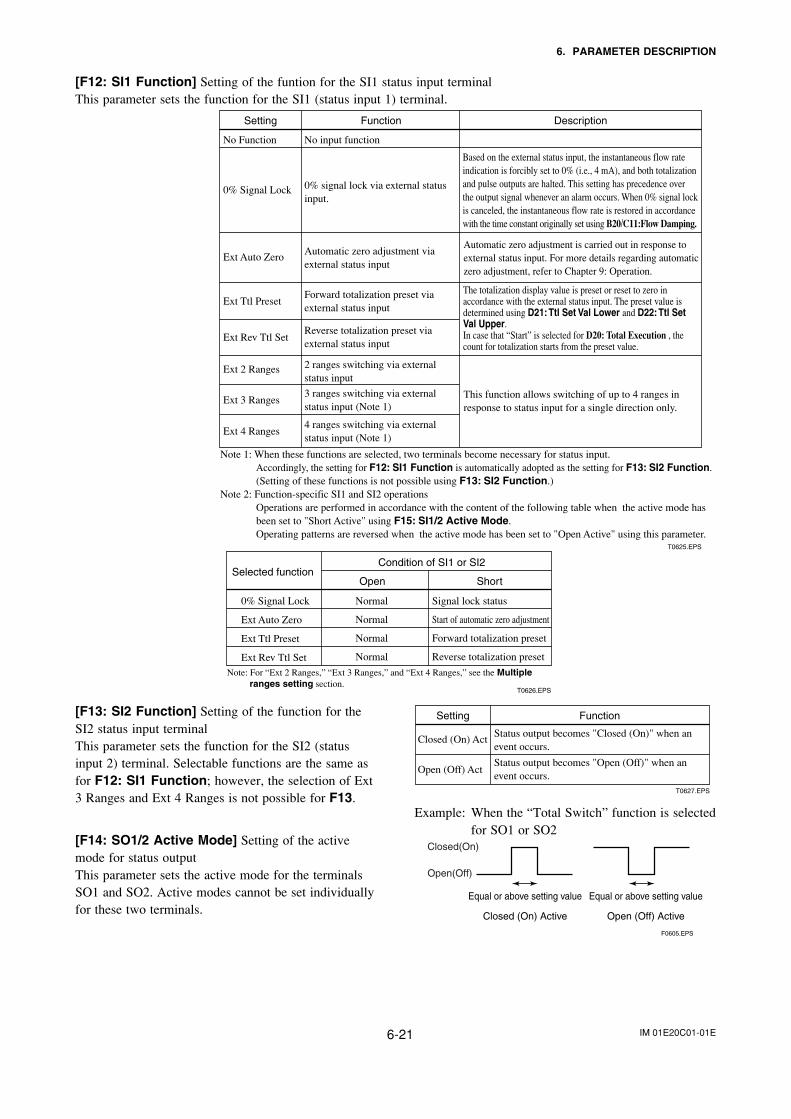
IM 01E20C01-01E6-21
6. PARAMETER DESCRIPTION
[F12: SI1 Function] Setting of the funtion for the SI1 status input terminalThis parameter sets the function for the SI1 (status input 1) terminal.
Setting
No Function No input function
0% Signal Lock 0% signal lock via external statusinput.
Ext Auto ZeroAutomatic zero adjustment via external status input
Ext Ttl PresetForward totalization preset via external status input
Ext Rev Ttl SetReverse totalization preset via external status input
Ext 2 Ranges 2 ranges switching via external status input
Ext 3 Ranges3 ranges switching via external status input (Note 1)
Ext 4 Ranges4 ranges switching via external status input (Note 1)
Automatic zero adjustment is carried out in response to external status input. For more details regarding automatic zero adjustment, refer to Chapter 9: Operation.
This function allows switching of up to 4 ranges in response to status input for a single direction only.
DescriptionFunction
T0625.EPS
Note 1: When these functions are selected, two terminals become necessary for status input. Accordingly, the setting for F12: SI1 Function is automatically adopted as the setting for F13: SI2 Function. (Setting of these functions is not possible using F13: SI2 Function.)
Note 2: Function-specific SI1 and SI2 operationsOperations are performed in accordance with the content of the following table when the active mode has been set to "Short Active" using F15: SI1/2 Active Mode. Operating patterns are reversed when the active mode has been set to "Open Active" using this parameter.
Based on the external status input, the instantaneous flow rate indication is forcibly set to 0% (i.e., 4 mA), and both totalizationand pulse outputs are halted. This setting has precedence over the output signal whenever an alarm occurs. When 0% signal lockis canceled, the instantaneous flow rate is restored in accordancewith the time constant originally set using B20/C11:Flow Damping.
The totalization display value is preset or reset to zero in accordance with the external status input. The preset value is determined using D21: Ttl Set Val Lower and D22: Ttl Set Val Upper. In case that “Start” is selected for D20: Total Execution , the count for totalization starts from the preset value.
Selected functionCondition of SI1 or SI2
ShortOpen
Signal lock status
Start of automatic zero adjustment
Forward totalization preset
Reverse totalization preset
Normal
Normal
Normal
Normal
0% Signal Lock
Ext Auto Zero
Ext Ttl Preset
Ext Rev Ttl Set
T0626.EPS
Note: For “Ext 2 Ranges,” “Ext 3 Ranges,” and “Ext 4 Ranges,” see the Multiple ranges setting section.
[F13: SI2 Function] Setting of the function for theSI2 status input terminalThis parameter sets the function for the SI2 (statusinput 2) terminal. Selectable functions are the same asfor F12: SI1 Function; however, the selection of Ext3 Ranges and Ext 4 Ranges is not possible for F13.
[F14: SO1/2 Active Mode] Setting of the activemode for status outputThis parameter sets the active mode for the terminalsSO1 and SO2. Active modes cannot be set individuallyfor these two terminals.
Setting Function
Closed (On) Act
Open (Off) Act
Status output becomes "Closed (On)" when an event occurs.
Status output becomes "Open (Off)" when an event occurs.
T0627.EPS
Example: When the “Total Switch” function is selectedfor SO1 or SO2
Equal or above setting value
Closed (On) Active
Equal or above setting value
Open (Off) Active
F0605.EPS
Closed(On)
Open(Off)
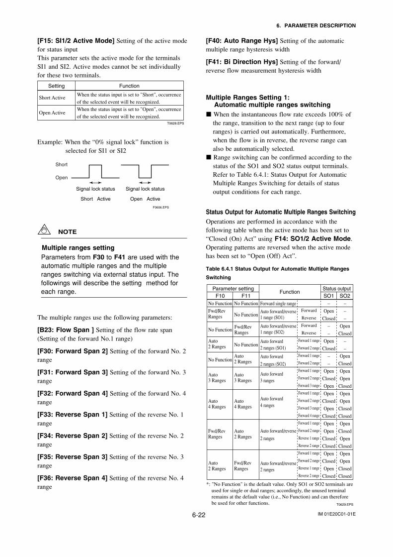
IM 01E20C01-01E6-22
6. PARAMETER DESCRIPTION
[F15: SI1/2 Active Mode] Setting of the active modefor status inputThis parameter sets the active mode for the terminalsSI1 and SI2. Active modes cannot be set individuallyfor these two terminals.
Setting Function
Short Active
Open Active
When the status input is set to "Short", occurrence of the selected event will be recognized.When the status input is set to "Open", occurrence of the selected event will be recognized.
T0628.EPS
Example: When the “0% signal lock” function isselected for SI1 or SI2
Signal lock status
Short Active
Signal lock status
Open Active
F0606.EPS
Short
Open
NOTE
Multiple ranges settingParameters from F30 to F41 are used with theautomatic multiple ranges and the multipleranges switching via external status input. Thefollowings will describe the setting method foreach range.
The multiple ranges use the following parameters:
[B23: Flow Span ] Setting of the flow rate span(Setting of the forward No.1 range)
[F30: Forward Span 2] Setting of the forward No. 2range
[F31: Forward Span 3] Setting of the forward No. 3range
[F32: Forward Span 4] Setting of the forward No. 4range
[F33: Reverse Span 1] Setting of the reverse No. 1range
[F34: Reverse Span 2] Setting of the reverse No. 2range
[F35: Reverse Span 3] Setting of the reverse No. 3range
[F36: Reverse Span 4] Setting of the reverse No. 4range
[F40: Auto Range Hys] Setting of the automaticmultiple range hysteresis width
[F41: Bi Direction Hys] Setting of the forward/reverse flow measurement hysteresis width
Multiple Ranges Setting 1:Automatic multiple ranges switching
When the instantaneous flow rate exceeds 100% ofthe range, transition to the next range (up to fourranges) is carried out automatically. Furthermore,when the flow is in reverse, the reverse range canalso be automatically selected.
Range switching can be confirmed according to thestatus of the SO1 and SO2 status output terminals.Refer to Table 6.4.1: Status Output for AutomaticMultiple Ranges Switching for details of statusoutput conditions for each range.
Status Output for Automatic Multiple Ranges SwitchingOperations are performed in accordance with thefollowing table when the active mode has been set to“Closed (On) Act” using F14: SO1/2 Active Mode.Operating patterns are reversed when the active modehas been set to “Open (Off) Act”.
Table 6.4.1 Status Output for Automatic Multiple Ranges
Switching
Parameter settingFunction
F10Status output
SO2SO1F11
T0629.EPS
–
–
–
Open
Closed
–
–
Open
Closed
Open
Open
Closed
Open
Open
Closed
Closed
Open
Closed
Open
Closed
Open
Open
Closed
Closed
–
Open
Closed
–
–
Open
Closed
–
–
Open
Closed
Open
Open
Closed
Open
Closed
Open
Open
Closed
Closed
Open
Closed
Open
Closed
No Function
Fwd/RevRanges
No Function
Auto 2 Ranges
No Function
Auto 3 Ranges
Auto 4 Ranges
Fwd/RevRanges
Auto 2 Ranges
No Function
No Function
No Function
Auto 2 Ranges
Auto 3 Ranges
Auto 4 Ranges
Auto 2 Ranges
Fwd/RevRanges
Forward single range
Auto forward/reverse 1 range (SO1)
Auto forward/reverse 1 range (SO2)
Auto forward 2 ranges (SO1)
Auto forward
2 ranges (SO2)
Auto forward 3 ranges
Auto forward 4 ranges
Auto forward/reverse
2 ranges
Auto forward/reverse 2 ranges
*: "No Function" is the default value. Only SO1 or SO2 terminals areused for single or dual ranges; accordingly, the unused terminal remains at the default value (i.e., No Function) and can thereforebe used for other functions.
Forward
Reverse
Forward
Reverse
Forward 1 range
Forward 2 range
Forward 1 range
Forward 2 range
Forward 1 range
Forward 2 range
Forward 3 range
Forward 1 range
Forward 2 range
Forward 3 range
Forward 4 range
Forward 1 range
Forward 2 range
Reverse 1 range
Reverse 2 range
Forward 1 range
Forward 2 range
Reverse 1 range
Reverse 2 range
Fwd/RevRanges
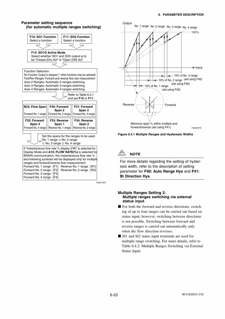
IM 01E20C01-01E6-23
6. PARAMETER DESCRIPTION
Parameter setting sequence(for automatic multiple ranges switching)
F10: SO1 FunctionSelect a function
F11: SO2 FunctionSelect a function
F14: SO1/2 Active ModeSelect whether SO1 and SO2 output is to be “Closed (On) Act” or “Open (Off) Act”
Function SelectionNo Function: Output is stopped (*: other functions may be selected)Fwd/Rev Ranges: Forward and reverse flow rate measurementAuto 2 Ranges: Automatic 2-ranges switchingAuto 3 Ranges: Automatic 3-ranges switchingAuto 4 Ranges: Automatic 4-ranges switching
Refer to Table 6.4.1 and set F10 or F11.
Set the spans for the ranges to be used.No. 1 range No. 2 range No. 3 range No. 4 range
If “instantaneous flow rate % display (FR)” is selected for Display Mode and A10: FLOW RATE(%) is selected for BRAIN communication, the instantaneous flow rate % and following symbols will be displayed only for multipleranges and forward/reverse flow measurement.Forward No. 1 range : [F1] Reverse No. 1 range : [R1]Forward No. 2 range : [F2] Reverse No. 2 range : [R2]Forward No. 3 range : [F3]Forward No. 4 range : [F4]
F30: Forward Span 2
Forward No. 2 range
B23: Flow Span
Forward No. 1 range
F31: Forward Span 3
Forward No. 3 range
F33: Reverse Span 1
Reverse No. 1 range
F34: Reverse Span 2
Reverse No. 2 range
F32: Forward Span 4
Forward No. 4 range
F0607.EPS
10% of No. 1 range (set using F40)
10% of No. 2 range (set using F40)
10% of No. 3 range (set using F40)
Input
100%
No. 1 range No. 2 range No. 3 range No. 4 range Output
Reverse Forward
Minimum span % within multiple and forward/reverse (set using F41) F0608.EPS
Figure 6.4.1 Multiple Ranges and Hysteresis Widths
NOTE
For more details regarding the setting of hyster-esis width, refer to the description of settingparameter for F40: Auto Range Hys and F41:Bi Direction Hys.
Multiple Ranges Setting 2:Multiple ranges switching via externalstatus input
For both the forward and reverse directions, switch-ing of up to four ranges can be carried out based onstatus input; however, switching between directionsis not possible. Switching between forward andreverse ranges is carried out automatically onlywhen the flow direction reverses.
SI1 and SI2 status input terminals are used formultiple range switching. For more details, refer toTable 6.4.2: Multiple Ranges Switching via ExternalStatus Input.

IM 01E20C01-01E6-24
6. PARAMETER DESCRIPTION
Multiple Ranges Switching via External Status InputOperations are performed in accordance with the following table when the active mode has been set to “Closed (On) Act” usingF14: SO1/2 Active Mode and when the active mode has been set to “Short Active” using F15: SI1/2 Active Mode.Operating patterns are reversed when the active mode has been set to “Open (Off) Act” using F14; and “Open Active”, usingF15.
Table 6.4.2 Multiple Ranges Switching via External Status Input
T0630.EPS
Parameter settingFunction
Status input Status outputSI2(F13)
––
OpenShortOpenOpenShortOpenOpenShortShort
OpenShortOpenShort
OpenShortOpenShortOpenOpenShortOpenOpenShortOpenOpenShortOpenOpenShortOpenOpenShortShortOpenOpenShortShortOpenOpenShortShortOpenOpenShortShort
OpenShort
OpenShortOpenOpenShortOpenOpenShortShort
OpenShortOpenShort
OpenShortOpenShort
SO1(F10)–––––––––––
OpenOpen
ClosedClosedOpenOpen
ClosedClosed
––––––––
OpenOpenOpen
ClosedClosedClosed
––––––
OpenOpenOpenOpen
ClosedClosedClosedClosed
––––––––
OpenClosedOpen
Closed––––
OpenClosedOpenOpen
ClosedOpen
ClosedOpenOpen
ClosedClosedOpenOpen
ClosedClosedOpen
ClosedOpen
ClosedOpen
ClosedOpen
Closed
SO2(F11)–––––––––––––––––––
OpenOpen
ClosedClosedOpenOpen
ClosedClosed
––––––
OpenOpenOpen
ClosedClosedClosed
––––––––
OpenOpenOpenOpen
ClosedClosedClosedClosed
––––
OpenClosedOpen
ClosedOpenOpen
ClosedOpenOpen
ClosedClosedOpen
ClosedOpen
ClosedOpen
ClosedOpen
ClosedOpenOpen
ClosedClosedOpenOpen
ClosedClosed
SI1(F12)OpenShort
––
OpenShortOpenOpenShortOpenShortOpenShortOpenShort
OpenShortOpenShort
OpenShortOpenOpenShortOpenOpenShortOpenOpenShortOpenOpenShortOpenShortOpenShortOpenShortOpenShortOpenShortOpenShortOpenShortOpenShort
OpenShort
OpenShortOpenOpenShortOpenShortOpenShortOpenShort
OpenShortOpenShort
F13
No Function
F12
Ext 2 Ranges
F11
No Function
F10
No Function External forward 2 ranges
External forward/reverse 4 ranges
External forward/reverse 2 ranges, with answerback
External forward 4 ranges, with answerback
External forward 3 ranges, with answerback
External forward 2 ranges, with answerback
External forward/reverse 3 ranges
External forward/reverse 2 ranges
External forward 4 ranges
External forward 3 ranges
Ext 2 RangesNo FunctionNo FunctionNo Function
Ext 3 RangesExt 3 RangesNo FunctionNo Function
Ext 4 RangesExt 4 RangesNo FunctionNo Function
No FunctionExt 2 RangesNo FunctionFwd/Rev Ranges
Ext 2 RangesNo FunctionNo FunctionFwd/Rev Ranges
No FunctionExt 2 RangesFwd/Rev Ranges
No Function
Ext 2 RangesNo FunctionFwd/Rev RangesNo Function
Ext 3 RangesExt 3 RangesNo FunctionFwd/Rev Ranges
Ext 3 RangesExt 3 RangesFwd/Rev RangesNo Function
Ext 4 RangesExt 4 RangesNo FunctionFwd/Rev Ranges
Ext 4 RangesExt 4 RangesFwd/Rev RangesNo Function
No FunctionExt 2 RangesNo FunctionExt 2 Answer
Ext 2 RangesNo FunctionNo FunctionExt 2 Answer
No FunctionExt 2 RangesExt 2 AnswerNo Function
Ext 2 RangesNo FunctionExt 2 AnswerNo Function
Ext 3 RangesExt 3 RangesExt 3 AnswerExt 3 Answer
Ext 4 RangesExt 4 RangesExt 4 AnswerExt 4 Answer
No FunctionExt 2 RangesExt 2 AnswerFwd/Rev Ranges
Ext 2 RangesNo FunctionExt 2 AnswerFwd/Rev Ranges
No FunctionExt 2 RangesFwd/Rev Ranges
Ext 2 Answer
Ext 2 RangesNo FunctionFwd/Rev Ranges
Ext 2 Answer
Forward 1 rangeForward 2 rangeForward 1 rangeForward 2 rangeForward 1 rangeForward 2 rangeForward 3 rangeForward 1 rangeForward 2 rangeForward 3 rangeForward 4 rangeForward 1 rangeForward 2 rangeReverse 1 rangeReverse 2 rangeForward 1 rangeForward 2 rangeReverse 1 rangeReverse 2 rangeForward 1 rangeForward 2 rangeReverse 1 rangeReverse 2 rangeForward 1 rangeForward 2 rangeReverse 1 rangeReverse 2 rangeForward 1 rangeForward 2 rangeForward 3 rangeReverse 1 rangeReverse 2 rangeReverse 3 rangeForward 1 rangeForward 2 rangeForward 3 rangeReverse 1 rangeReverse 2 rangeReverse 3 rangeForward 1 rangeForward 2 rangeForward 3 rangeForward 4 rangeReverse 1 rangeReverse 2 rangeReverse 3 rangeReverse 4 rangeForward 1 rangeForward 2 rangeForward 3 rangeForward 4 rangeReverse 1 rangeReverse 2 rangeReverse 3 rangeReverse 4 rangeForward 1 rangeForward 2 rangeForward 1 rangeForward 2 rangeForward 1 rangeForward 2 rangeForward 1 rangeForward 2 rangeForward 1 rangeForward 2 rangeForward 3 rangeForward 1 rangeForward 2 rangeForward 3 rangeForward 4 rangeForward 1 rangeForward 2 rangeReverse 1 rangeReverse 2 rangeForward 1 rangeForward 2 rangeReverse 1 rangeReverse 2 rangeForward 1 rangeForward 2 rangeReverse 1 rangeReverse 2 rangeForward 1 rangeForward 2 rangeReverse 1 rangeReverse 2 range
*: "No Function" is the default value. Only SI1 or SI2 terminals are used for single or dual ranges; accordingly, the unused terminal remains at the default value (i.e., No Function) and can therefore be used for other functions.
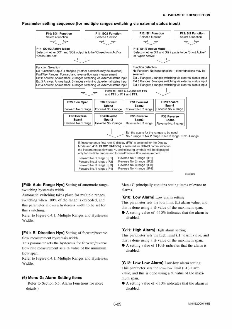
IM 01E20C01-01E6-25
6. PARAMETER DESCRIPTION
Parameter setting sequence (for multiple ranges switching via external status input)
F10: SO1 FunctionSelect a function
F11: SO2 FunctionSelect a function
F14: SO1/2 Active ModeSelect whether SO1 and SO2 output is to be “Closed (on) Act” or “Open (off) Act.”
Function SelectionNo Function: Output is stopped (*: other functions may be selected)Fwd/Rev Ranges: Forward and reverse flow rate measurementExt 2 Answer: Answerback; 2-ranges switching via external status inputExt 3 Answer: Answerback; 3-ranges switching via external status inputExt 4 Answer: Answerback; 4-ranges switching via external status input
Function SelectionNo Function: No input function (*: other functions may be selected)Ext 2 Ranges: 2-ranges switching via external status inputExt 3 Ranges: 3-ranges switching via external status inputExt 4 Ranges: 4-ranges switching via external status input
Refer to Table 6.4.2 and set F10 and F11 or F12 and F13.
Set the spans for the ranges to be used.No. 1 range No. 2 range No. 3 range No. 4 range
F12: SI1 FunctionSelect a function
F13: SI2 FunctionSelect a function
F15: SI1/2 Active ModeSelect whether SI1 and SI2 input is to be “Short Active” or “Open Active.”
F33:ReverseSpan1
Reverse No. 1 range
B23:Flow Span
Forward No. 1 range
F0609.EPS
F34:ReverseSpan2
Reverse No. 2 range
F35:ReverseSpan3
Reverse No. 3 range
F36:ReverseSpan4
Reverse No. 4 range
F30:ForwardSpan2
Forward No. 2 range
F31:ForwardSpan3
Forward No. 3 range
F32:ForwardSpan4
Forward No. 4 range
If “instantaneous flow rate % display (FR)” is selected for the Display Mode and A10: FLOW RATE(%) is selected for BRAIN communication, the instantaneous flow rate % and following symbols will be displayed only for multiple ranges and forward/reverse flow measurement.
Forward No. 1 range : [F1]Forward No. 2 range : [F2]Forward No. 3 range : [F3]Forward No. 4 range : [F4]
Reverse No. 1 range : [R1]Reverse No. 2 range : [R2]Reverse No. 3 range : [R3]Reverse No. 4 range : [R4]
[F40: Auto Range Hys] Setting of automatic range-switching hysteresis widthAutomatic switching takes place for multiple rangesswitching when 100% of the range is exceeded, andthis parameter allows a hysteresis width to be set forthis switching.Refer to Figure 6.4.1: Multiple Ranges and HysteresisWidths.
[F41: Bi Direction Hys] Setting of forward/reverseflow measurement hysteresis widthThis parameter sets the hysteresis for forward/reverseflow rate measurement as a % value of the minimumflow span.Refer to Figure 6.4.1: Multiple Ranges and HysteresisWidths.
(6) Menu G: Alarm Setting items(Refer to Section 6.5: Alarm Functions for moredetails.)
Menu G principally contains setting items relevant toalarms.
[G10: Low Alarm] Low alarm settingThis parameter sets the low limit (L) alarm value, andthis is done using a % value of the maximum span. A setting value of -110% indicates that the alarm is
disabled.
[G11: High Alarm] High alarm settingThis parameter sets the high limit (H) alarm value, andthis is done using a % value of the maximum span. A setting value of 110% indicates that the alarm is
disabled.
[G12: Low Low Alarm] Low-low alarm settingThis parameter sets the low-low limit (LL) alarmvalue, and this is done using a % value of the maxi-mum span. A setting value of -110% indicates that the alarm is
disabled.
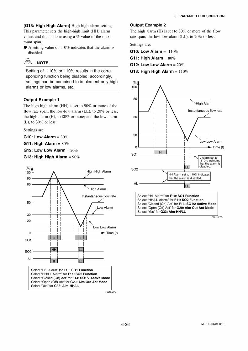
IM 01E20C01-01E6-26
6. PARAMETER DESCRIPTION
[G13: High High Alarm] High-high alarm settingThis parameter sets the high-high limit (HH) alarmvalue, and this is done using a % value of the maxi-mum span. A setting value of 110% indicates that the alarm is
disabled.
NOTE
Setting of -110% or 110% results in the corre-sponding function being disabled; accordingly,settings can be combined to implement only highalarms or low alarms, etc.
Output Example 1The high-high alarm (HH) is set to 90% or more of theflow rate span; the low-low alarm (LL), to 20% or less;the high alarm (H), to 80% or more; and the low alarm(L), to 30% or less.
Settings are:
G10: Low Alarm = 30%
G11: High Alarm = 80%
G12: Low Low Alarm = 20%
G13: High High Alarm = 90%
0 Time (t)
H L
HH
SO1
SO2LL
HHAL
LL
High High Alarm
High Alarm
Instantaneous flow rate
Low Alarm
Low Low Alarm
20
30
50
80
90
100[%]
Select “H/L Alarm” for F10: SO1 FunctionSelect “HH/LL Alarm” for F11: SO2 FunctionSelect “Closed (On) Act” for F14: SO1/2 Active ModeSelect “Open (Off) Act” for G20: Alm Out Act ModeSelect “Yes” for G33: Alm-HH/LL
F0610.EPS
Output Example 2The high alarm (H) is set to 80% or more of the flowrate span; the low-low alarm (LL), to 20% or less.
Settings are:
G10: Low Alarm = -110%
G11: High Alarm = 80%
G12: Low Low Alarm = 20%
G13: High High Alarm = 110%
0 Time (t)
HSO1
SO2LL
ALLL
Instantaneous flow rate
20
50
80
100[%]
F0611.EPS
L Alarm set to -110% indicates that the alarm is disabled.
High Alarm
Low Low Alarm
HH Alarm set to 110% indicatesthat the alarm is disabled.
Select “H/L Alarm” for F10: SO1 FunctionSelect “HH/LL Alarm” for F11: SO2 FunctionSelect “Closed (On) Act” for F14: SO1/2 Active ModeSelect “Open (Off) Act” for G20: Alm Out Act ModeSelect “Yes” for G33: Alm-HH/LL
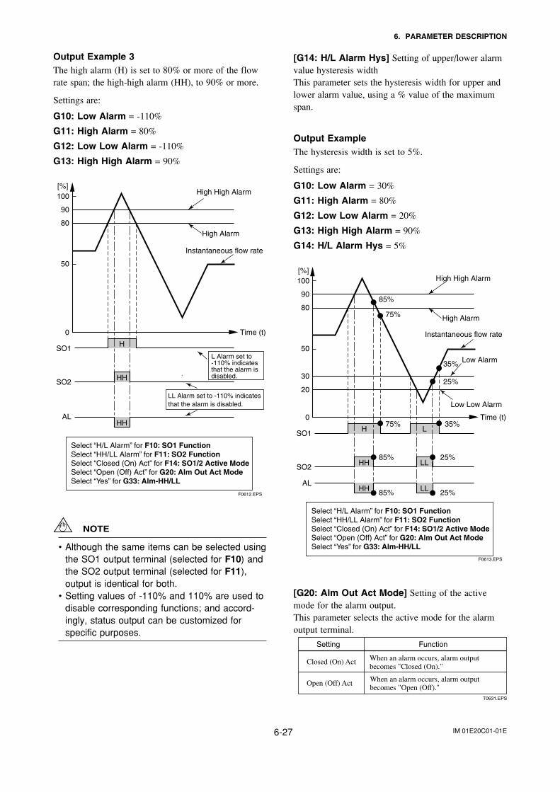
IM 01E20C01-01E6-27
6. PARAMETER DESCRIPTION
Output Example 3The high alarm (H) is set to 80% or more of the flowrate span; the high-high alarm (HH), to 90% or more.
Settings are:
G10: Low Alarm = -110%
G11: High Alarm = 80%
G12: Low Low Alarm = -110%
G13: High High Alarm = 90%
0 Time (t)
H
HH
SO1
SO2
HHAL
Instantaneous flow rate
50
80
90
100[%]
F0612.EPS
High High Alarm
High Alarm
L Alarm set to -110% indicates that the alarm is disabled.
LL Alarm set to -110% indicatesthat the alarm is disabled.
Select “H/L Alarm” for F10: SO1 FunctionSelect “HH/LL Alarm” for F11: SO2 FunctionSelect “Closed (On) Act” for F14: SO1/2 Active ModeSelect “Open (Off) Act” for G20: Alm Out Act ModeSelect “Yes” for G33: Alm-HH/LL
NOTE
• Although the same items can be selected usingthe SO1 output terminal (selected for F10) andthe SO2 output terminal (selected for F11),output is identical for both.
• Setting values of -110% and 110% are used todisable corresponding functions; and accord-ingly, status output can be customized forspecific purposes.
[G14: H/L Alarm Hys] Setting of upper/lower alarmvalue hysteresis widthThis parameter sets the hysteresis width for upper andlower alarm value, using a % value of the maximumspan.
Output ExampleThe hysteresis width is set to 5%.
Settings are:
G10: Low Alarm = 30%
G11: High Alarm = 80%
G12: Low Low Alarm = 20%
G13: High High Alarm = 90%
G14: H/L Alarm Hys = 5%
0 Time (t)
H L
HH
SO1
SO2LL
75%
75%
35%
35%
85%
85%
25%
85% 25%
Instantaneous flow rate
20
30
50
80
90
100[%]
F0613.EPS
HHAL
LL
High High Alarm
High Alarm
Low Alarm
Low Low Alarm
25%
Select “H/L Alarm” for F10: SO1 FunctionSelect “HH/LL Alarm” for F11: SO2 FunctionSelect “Closed (On) Act” for F14: SO1/2 Active ModeSelect “Open (Off) Act” for G20: Alm Out Act ModeSelect “Yes” for G33: Alm-HH/LL
[G20: Alm Out Act Mode] Setting of the activemode for the alarm output.This parameter selects the active mode for the alarmoutput terminal.
Closed (On) Act
Open (Off) Act
When an alarm occurs, alarm output becomes "Closed (On)."
T0631.EPS
Setting Function
When an alarm occurs, alarm output becomes "Open (Off)."
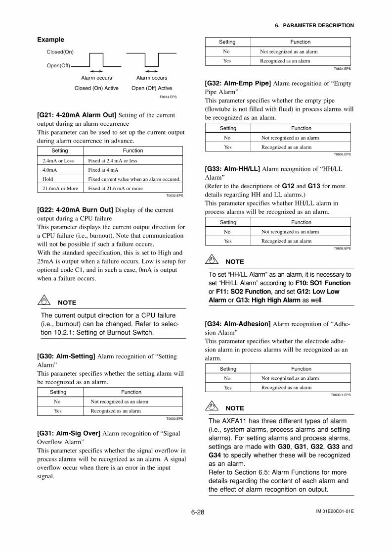
IM 01E20C01-01E6-28
6. PARAMETER DESCRIPTION
Example
Alarm occurs
Closed (On) Active
Alarm occurs
Open (Off) Active
F0614.EPS
Closed(On)
Open(Off)
[G21: 4-20mA Alarm Out] Setting of the currentoutput during an alarm occurrenceThis parameter can be used to set up the current outputduring alarm occurrence in advance.
Fixed at 2.4 mA or less
Fixed at 4 mA
Fixed current value when an alarm occured.
Fixed at 21.6 mA or more
2.4mA or Less
4.0mA
Hold
21.6mA or MoreT0632.EPS
Setting Function
[G22: 4-20mA Burn Out] Display of the currentoutput during a CPU failureThis parameter displays the current output direction fora CPU failure (i.e., burnout). Note that communicationwill not be possible if such a failure occurs.With the standard specification, this is set to High and25mA is output when a failure occurs. Low is setup foroptional code C1, and in such a case, 0mA is outputwhen a failure occurs.
NOTE
The current output direction for a CPU failure(i.e., burnout) can be changed. Refer to selec-tion 10.2.1: Setting of Burnout Switch.
[G30: Alm-Setting] Alarm recognition of “SettingAlarm”This parameter specifies whether the setting alarm willbe recognized as an alarm.
T0633.EPS
Setting Function
Not recognized as an alarm
Recognized as an alarm
No
Yes
[G31: Alm-Sig Over] Alarm recognition of “SignalOverflow Alarm”This parameter specifies whether the signal overflow inprocess alarms will be recognized as an alarm. A signaloverflow occur when there is an error in the inputsignal.
T0634.EPS
Setting Function
No
Yes
Not recognized as an alarm
Recognized as an alarm
[G32: Alm-Emp Pipe] Alarm recognition of “EmptyPipe Alarm”This parameter specifies whether the empty pipe(flowtube is not filled with fluid) in process alarms willbe recognized as an alarm.
Setting Function
No
YesT0635.EPS
Not recognized as an alarm
Recognized as an alarm
[G33: Alm-HH/LL] Alarm recognition of “HH/LLAlarm”(Refer to the descriptions of G12 and G13 for moredetails regarding HH and LL alarms.)This parameter specifies whether HH/LL alarm inprocess alarms will be recognized as an alarm.
Setting Function
No
YesT0636.EPS
Not recognized as an alarm
Recognized as an alarm
NOTE
To set “HH/LL Alarm” as an alarm, it is necessary toset “HH/LL Alarm” according to F10: SO1 Functionor F11: SO2 Function, and set G12: Low LowAlarm or G13: High High Alarm as well.
[G34: Alm-Adhesion] Alarm recognition of “Adhe-sion Alarm”This parameter specifies whether the electrode adhe-sion alarm in process alarms will be recognized as analarm.
Setting Function
No
YesT0636-1.EPS
Not recognized as an alarm
Recognized as an alarm
NOTE
The AXFA11 has three different types of alarm(i.e., system alarms, process alarms and settingalarms). For setting alarms and process alarms,settings are made with G30, G31, G32, G33 andG34 to specify whether these will be recognizedas an alarm.Refer to Section 6.5: Alarm Functions for moredetails regarding the content of each alarm andthe effect of alarm recognition on output.
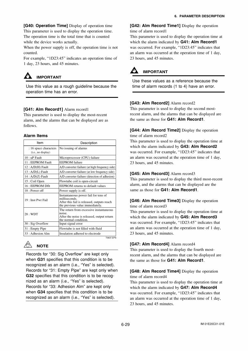
IM 01E20C01-01E6-29
6. PARAMETER DESCRIPTION
[G40: Operation Time] Display of operation timeThis parameter is used to display the operation time.The operation time is the total time that is countedwhile the device works actually.When the power supply is off, the operation time is notcounted.For example, “1D23:45” indicates an operation time of1 day, 23 hours, and 45 minutes.
IMPORTANT
Use this value as a rough guideline because theoperation time has an error.
[G41: Alm Record1] Alarm record1This parameter is used to display the most-recentalarm, and the alarms that can be displayed are asfollows.
Alarm Items
T0637.EPS
Item Description
No issuing of alarms
Microprocessor (CPU) failure
EEPROM failure
A/D converter failure (at high frequency side)
A/D converter failure (at low frequency side)
A/D converter failure (detection of adhesion)
Flowtube coil is open-circuit
EEPROM returns to default values
Power supply is off.
Instantaneous power fail for tens of milliseconds.After this fail is released, outputs reachthe previous value immediately.The return from excessive instantaneousnoise.After the noise is released, output returnthe normal condition.Input signal error
Flowtube is not filled with fluid
Insulation adhered to electrode
: 16 space characters (i.e., no display)
10 : uP Fault
11 : EEPROM Fault
12 : A/D(H) Fault
13 : A/D(L) Fault
14 : A/D(Z) Fault
15 : Coil Open
16 : EEPROM Dflt
18 : Power off
19 : Inst Pwr Fail
28 : WDT
30 : Sig Overflow
31 : Empty Pipe
33 : Adhesion Alm
NOTE
Records for “30: Sig Overflow” are kept onlywhen G31 specifies that this condition is to berecognized as an alarm (i.e., “Yes” is selected).Records for “31: Empty Pipe” are kept only whenG32 specifies that this condition is to be recog-nized as an alarm (i.e., “Yes” is selected).Records for “33: Adhesion Alm” are kept onlywhen G34 specifies that this condition is to berecognized as an alarm (i.e., “Yes” is selected).
[G42: Alm Record Time1] Display the operationtime of alarm record1This parameter is used to display the operation time atwhich the alarm indicated by G41: Alm Record1was occurred. For example, “1D23:45” indicates thatan alarm was occurred at the operation time of 1 day,23 hours, and 45 minutes.
IMPORTANT
Use these values as a reference because thetime of alarm records (1 to 4) have an error.
[G43: Alm Record2] Alarm record2This parameter is used to display the second most-recent alarm, and the alarms that can be displayed arethe same as those for G41: Alm Record1.
[G44: Alm Record Time2] Display the operationtime of alarm record2This parameter is used to display the operation time atwhich the alarm indicated by G43: Alm Record2was occurred. For example, “1D23:45” indicates thatan alarm was occurred at the operation time of 1 day,23 hours, and 45 minutes.
[G45: Alm Record3] Alarm record3This parameter is used to display the third most-recentalarm, and the alarms that can be displayed are thesame as those for G41: Alm Record1.
[G46: Alm Record Time3] Display the operationtime of alarm record3This parameter is used to display the operation time atwhich the alarm indicated by G45: Alm Record3was occurred. For example, “1D23:45” indicates thatan alarm was occurred at the operation time of 1 day,23 hours, and 45 minutes.
[G47: Alm Record4] Alarm record4This parameter is used to display the fourth most-recent alarm, and the alarms that can be displayed arethe same as those for G41: Alm Record1.
[G48: Alm Record Time4] Display the operationtime of alarm record4This parameter is used to display the operation time atwhich the alarm indicated by G47: Alm Record4was occurred. For example, “1D23:45” indicates thatan alarm was occurred at the operation time of 1 day,23 hours, and 45 minutes.
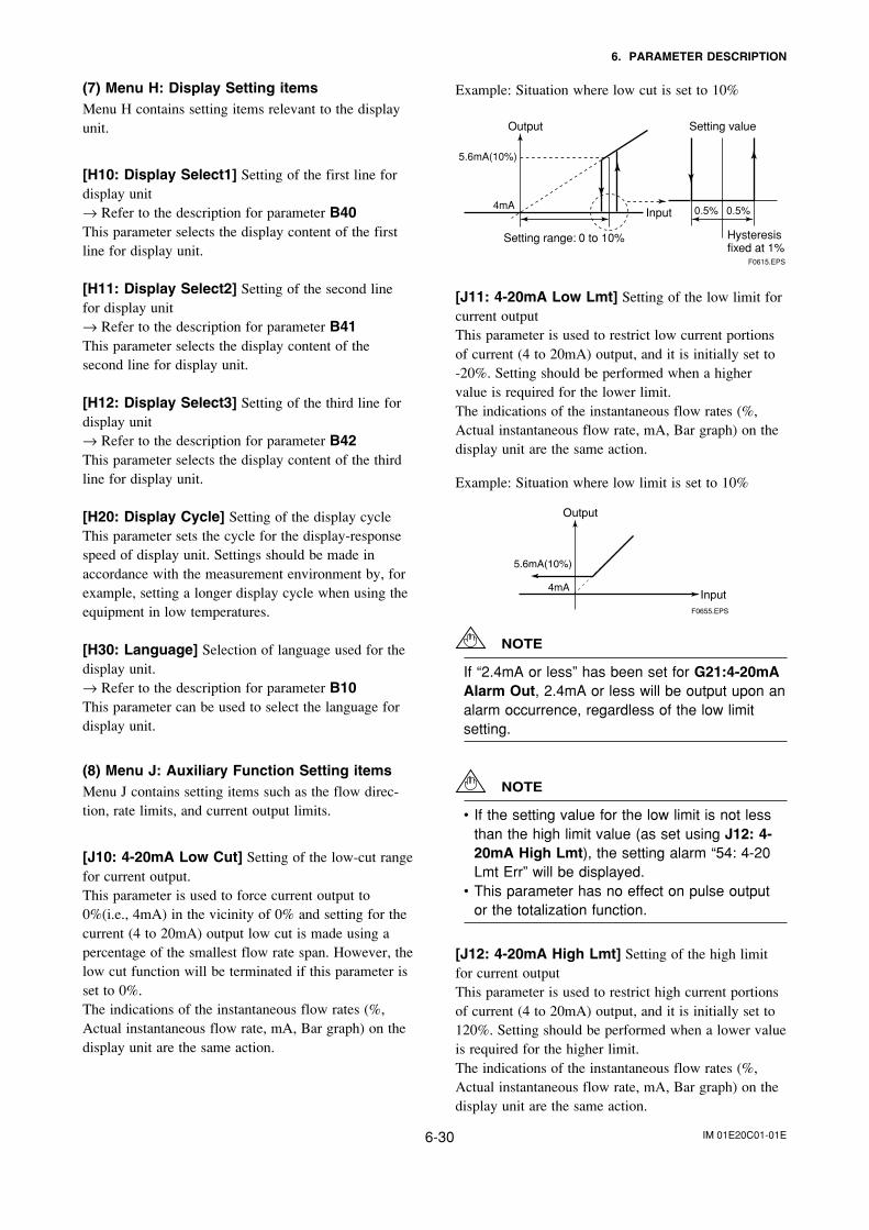
IM 01E20C01-01E6-30
6. PARAMETER DESCRIPTION
(7) Menu H: Display Setting itemsMenu H contains setting items relevant to the displayunit.
[H10: Display Select1] Setting of the first line fordisplay unit→ Refer to the description for parameter B40This parameter selects the display content of the firstline for display unit.
[H11: Display Select2] Setting of the second linefor display unit→ Refer to the description for parameter B41This parameter selects the display content of thesecond line for display unit.
[H12: Display Select3] Setting of the third line fordisplay unit→ Refer to the description for parameter B42This parameter selects the display content of the thirdline for display unit.
[H20: Display Cycle] Setting of the display cycleThis parameter sets the cycle for the display-responsespeed of display unit. Settings should be made inaccordance with the measurement environment by, forexample, setting a longer display cycle when using theequipment in low temperatures.
[H30: Language] Selection of language used for thedisplay unit.→ Refer to the description for parameter B10This parameter can be used to select the language fordisplay unit.
(8) Menu J: Auxiliary Function Setting itemsMenu J contains setting items such as the flow direc-tion, rate limits, and current output limits.
[J10: 4-20mA Low Cut] Setting of the low-cut rangefor current output.This parameter is used to force current output to0%(i.e., 4mA) in the vicinity of 0% and setting for thecurrent (4 to 20mA) output low cut is made using apercentage of the smallest flow rate span. However, thelow cut function will be terminated if this parameter isset to 0%.The indications of the instantaneous flow rates (%,Actual instantaneous flow rate, mA, Bar graph) on thedisplay unit are the same action.
Example: Situation where low cut is set to 10%
F0615.EPS
Setting range: 0 to 10%
0.5% 0.5%4mA
Output Setting value
Input
Hysteresis fixed at 1%
5.6mA(10%)
[J11: 4-20mA Low Lmt] Setting of the low limit forcurrent outputThis parameter is used to restrict low current portionsof current (4 to 20mA) output, and it is initially set to-20%. Setting should be performed when a highervalue is required for the lower limit.The indications of the instantaneous flow rates (%,Actual instantaneous flow rate, mA, Bar graph) on thedisplay unit are the same action.
Example: Situation where low limit is set to 10%
F0655.EPS
4mA
Output
Input
5.6mA(10%)
NOTE
If “2.4mA or less” has been set for G21:4-20mAAlarm Out, 2.4mA or less will be output upon analarm occurrence, regardless of the low limitsetting.
NOTE
• If the setting value for the low limit is not lessthan the high limit value (as set using J12: 4-20mA High Lmt), the setting alarm “54: 4-20Lmt Err” will be displayed.
• This parameter has no effect on pulse outputor the totalization function.
[J12: 4-20mA High Lmt] Setting of the high limitfor current outputThis parameter is used to restrict high current portionsof current (4 to 20mA) output, and it is initially set to120%. Setting should be performed when a lower valueis required for the higher limit.The indications of the instantaneous flow rates (%,Actual instantaneous flow rate, mA, Bar graph) on thedisplay unit are the same action.
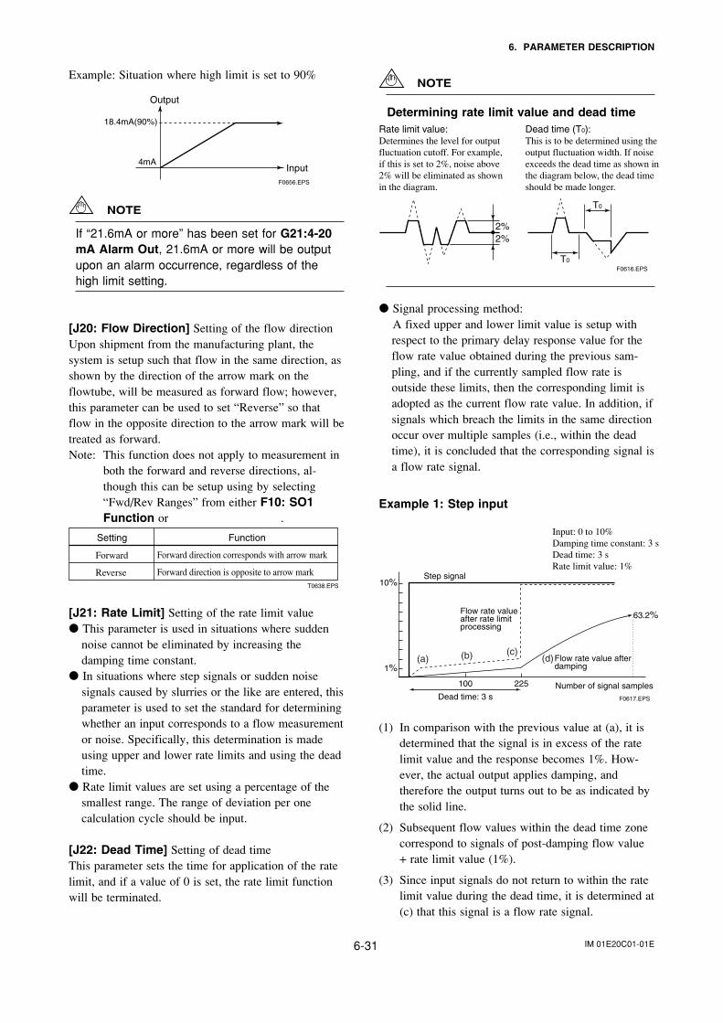
IM 01E20C01-01E6-31
6. PARAMETER DESCRIPTION
Example: Situation where high limit is set to 90%
F0656.EPS
4mA
Output
Input
18.4mA(90%)
NOTE
If “21.6mA or more” has been set for G21:4-20mA Alarm Out, 21.6mA or more will be outputupon an alarm occurrence, regardless of thehigh limit setting.
[J20: Flow Direction] Setting of the flow directionUpon shipment from the manufacturing plant, thesystem is setup such that flow in the same direction, asshown by the direction of the arrow mark on theflowtube, will be measured as forward flow; however,this parameter can be used to set “Reverse” so thatflow in the opposite direction to the arrow mark will betreated as forward.Note: This function does not apply to measurement in
both the forward and reverse directions, al-though this can be setup using by selecting“Fwd/Rev Ranges” from either F10: SO1Function or .
Setting Function
Forward direction corresponds with arrow mark
Forward direction is opposite to arrow mark
Forward
ReverseT0638.EPS
[J21: Rate Limit] Setting of the rate limit value This parameter is used in situations where sudden
noise cannot be eliminated by increasing thedamping time constant.
In situations where step signals or sudden noisesignals caused by slurries or the like are entered, thisparameter is used to set the standard for determiningwhether an input corresponds to a flow measurementor noise. Specifically, this determination is madeusing upper and lower rate limits and using the deadtime.
Rate limit values are set using a percentage of thesmallest range. The range of deviation per onecalculation cycle should be input.
[J22: Dead Time] Setting of dead timeThis parameter sets the time for application of the ratelimit, and if a value of 0 is set, the rate limit functionwill be terminated.
NOTE
Determining rate limit value and dead time
F0616.EPS
T0
T0
2%2%
Rate limit value:Determines the level for output fluctuation cutoff. For example, if this is set to 2%, noise above 2% will be eliminated as shown in the diagram.
Dead time (T0):This is to be determined using the output fluctuation width. If noise exceeds the dead time as shown in the diagram below, the dead time should be made longer.
Signal processing method:A fixed upper and lower limit value is setup withrespect to the primary delay response value for theflow rate value obtained during the previous sam-pling, and if the currently sampled flow rate isoutside these limits, then the corresponding limit isadopted as the current flow rate value. In addition, ifsignals which breach the limits in the same directionoccur over multiple samples (i.e., within the deadtime), it is concluded that the corresponding signal isa flow rate signal.
Example 1: Step input
F0617.EPS
10%
1%
Step signal
Flow rate valueafter rate limitprocessing
63.2%
100 225
Dead time: 3 s
Input: 0 to 10%Damping time constant: 3 sDead time: 3 sRate limit value: 1%
Number of signal samples
Flow rate value after damping
(a) (b) (c)(d)
(1) In comparison with the previous value at (a), it isdetermined that the signal is in excess of the ratelimit value and the response becomes 1%. How-ever, the actual output applies damping, andtherefore the output turns out to be as indicated bythe solid line.
(2) Subsequent flow values within the dead time zonecorrespond to signals of post-damping flow value+ rate limit value (1%).
(3) Since input signals do not return to within the ratelimit value during the dead time, it is determined at(c) that this signal is a flow rate signal.
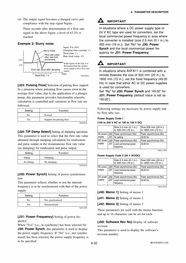
IM 01E20C01-01E6-32
6. PARAMETER DESCRIPTION
(4) The output signal becomes a damped curve andcompliance with the step signal begins.
Three seconds after determination of a flow ratesignal in the above figure, a level of 63.2% isreached.
Example 2: Slurry noise
F0618.EPS
+1%
-1%
Dead time: 1 s
Flow rate value after damping
Flow rate value after rate limit processing
Slurry noise
Input: 0 to 10%Damping time constant: 1 sDead time: 1 sRate limit value: 1%
Time
In the figure on the left, it is determined that the slurries noise signal is not a flow rate signal.
[J23: Pulsing Flow] Selection of pulsing flow supportIn a situation where pulsating flow causes error in theaverage flow value, due to the application of a plungerpump, this parameter provides functionality wherebycalculation is controlled and variations in flow rate arefollowed.
Setting Function
Normal
Support for pulsing flow
No
YesT0639.EPS
[J24: T/P Damp Select] Setting of damping operationThis parameter is used to select that the flow rate valueobtained through damping calculation for totalizationand pulse output or the instantaneous flow rate value(no damping) for totalization and pulse output.
Setting Function
Damping
No damping
Damp
No DampT0640.EPS
[J30: Power Synch] Setting of power synchroniza-tionThis parameter sellects whether or not the internalfrequency is to be synchronized with that of the powersupply.
Setting Function
Not synchronized
Synchronized
No
YesT0641.EPS
[J31: Power Frequency] Setting of power fre-quencyWhen “Yes” (i.e., in synchrony) has been selected forJ30: Power Synch, this parameter is used to displaythe power supply frequency. If “No” (i.e., not synchro-nized) has been selected, the power supply frequency isto be specified.
IMPORTANT
In situations where a DC power supply type or24 V AC type are used for converters, set thelocal commercial power frequency in area wherethe converter is installed (size 2.5 mm (0.1 in.) to400 mm (16 in.)). Set “No” for J30: PowerSynch and the local commercial power fre-quency for J31: Power Frequency.
IMPORTANT
In situations where AXFA11 is combined with aremote flowtube the size of 500 mm (20 in.) to1800 mm (72 in.), set the fixed frequency (49.00Hz) in case that either AC or DC power suppliesis used for converters.Set “No” for J30: Power Synch and “49.00” forJ31: Power Frequency (default value is set as“49.00”).
Following settings are necessary by power supply andby flow tube size.
Power Supply Code 1
(100 to 240 V AC or 100 to 120 V DC)
T0642-1.EPS
J30J31J30J31
Size 2.5 mm (0.1 in.) to 400 mm (16 in.)
Power synchronous (Yes)No setting
Power asynchronous (No)49.00 Hz
Power asynchronous (No) Power asynchronous (No)Local commercial power frequency
49.00 Hz
AC power supply
DC power supply
Size 500 mm (20 in.) to 1800 mm (72 in.)
Power Supply Code 2 (24 V AC/DC)
T0642-2.EPS
J30J31
J30J31
Size 2.5 mm (0.1 in.) to 400 mm (16 in.)
Power asynchronous (No)Local commercial power frequency
Power asynchronous (No)49.00 Hz
Power asynchronous (No) Power asynchronous (No)Local commercial power frequency
49.00 Hz
AC power supply
DC power supply
Size 500 mm (20 in.) to 1800 mm (72 in.)
[J40: Memo 1] Setting of memo 1
[J41: Memo 2] Setting of memo 2
[J42: Memo 3] Setting of memo 3
These parameters are used with the memo function,and up to 16 characters can be set for each.
[J50: Software Rev No] Display of softwarerevisionThis parameter is used to display the software’srevision number.
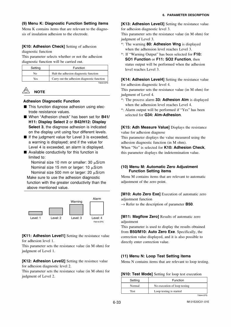
IM 01E20C01-01E6-33
6. PARAMETER DESCRIPTION
(9) Menu K: Diagnostic Function Setting itemsMenu K contains items that are relevant to the diagno-sis of insulation adhesion to the electrode.
[K10: Adhesion Check] Setting of adhesiondiagnostic functionThis parameter selects whether or not the adhesiondiagnostic function will be carried out.
Setting Function
Halt the adhesion diagnostic functionNo
YesT0642.EPS
Carry out the adhesion diagnostic function
NOTE
Adhesion Diagnostic Function This function diagnose adhesion using elec-
trode resistance values. When “Adhesion check” has been set for B41/
H11: Display Select 2 or B42/H12: DisplaySelect 3, the diagnose adhesion is indicatedon the display unit using four different levels.
If the judgment value for Level 3 is exceeded,a warning is displayed; and if the value forLevel 4 is exceeded, an alarm is displayed.
Available conductivity for this function islimited to: Nominal size 10 mm or smaller: 30 S/cm Nominal size 15 mm or larger: 10 S/cm Nominal size 500 mm or larger: 20 S/cm
Make sure to use the adhesion diagnosticfunction with the greater conductivity than theabove mentioned value.
F0619.EPS
Alarm
Level: 4
Warning
Level: 3Level: 2Level: 1
[K11: Adhesion Level1] Setting the resistance valuefor adhesion level 1.This parameter sets the resistance value (in M ohm) forjudgment of Level 1.
[K12: Adhesion Level2] Setting the resistnce valuefor adhesion diagnostic level 2.This parameter sets the resistance value (in M ohm) forjudgment of Level 2.
[K13: Adhesion Level3] Setting the resistance valuefor adhesion diagnostic level 3.This parameter sets the resistance value (in M ohm) forjudgment of Level 3.*: The warning 80: Adhesion Wng is displayed
when the adhension level reaches Level 3.*: If “Warning Output” has been selected for F10:
SO1 Function or F11: SO2 Function, thenstatus output will be performed when the adhesionlevel reaches Level 3.
[K14: Adhesion Level4] Setting the resistance valuefor adhesion diagnostic level 4.This parameter sets the resistance value (in M ohm) forjudgment of Level 4.*: The process alarm 33: Adhesion Alm is displayed
when the adhension level reaches Level 4.*: Alarm output will be performed if “Yes” has been
selected for G34: Alm-Adhesion.
[K15: Adh Measure Value] Displays the resistancevalue for adhesion diagnoseThis parameter displays the value measured using theadhesion diagnostic function (in M ohm).When “No” is selected for K10: Adhesion Check,this parameter displays the indetermination value.
(10) Menu M: Automatic Zero AdjustmentFunction Setting items
Menu M contains items that are relevant to automaticadjustment of the zero point.
[M10: Auto Zero Exe] Execution of automatic zeroadjustment function→ Refer to the description of parameter B50.
[M11: Magflow Zero] Results of automatic zeroadjustmentThis parameter is used to display the results obtainedfrom B50/M10: Auto Zero Exe. Specifically, thecorrection value displayed, and it is also possible todirectly enter correction value.
(11) Menu N: Loop Test Setting itemsMenu N contains items that are relevant to loop testing.
[N10: Test Mode] Setting for loop test execution
Setting Function
No execution of loop testing
Loop testing is started
Normal
TestT0644.EPS
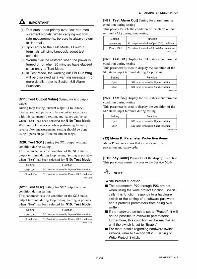
IM 01E20C01-01E6-34
6. PARAMETER DESCRIPTION
IMPORTANT
(1) Test output has priority over flow rate mea-surement signals. When carrying out flowrate measurements, be sure to always returnto “Normal”.
(2) Upon entry to the Test Mode, all outputterminals will simultaneously adopt testcondition.
(3) “Normal” will be restored when the power isturned off or when 30 minutes have elapsedsince entry to Test Mode.
(4) In Test Mode, the warning 83: Fix Cur Wngwill be displayed as a warning message. (Formore details, refer to Section 6.5 AlarmFunctions.)
[N11: Test Output Value] Setting for test outputvaluesDuring loop testing, current output (4 to 20mA),totalization, and pulse will be output in accordancewith this parameter’s setting, and values can be setwhen “Test” has been selected for N10: Test Mode.With multiple ranges or when performing forward/reverse flow measurements, setting should be doneusing a percentage of the maximum range.
[N20: Test SO1] Setting for SO1 output terminalcondition during testingThis parameter sets the condition of the SO1 statusoutput terminal during loop testing. Setting is possiblewhen “Test” has been selected for N10: Test Mode.
Setting Function
SO1 output terminal in Open (Off) condition
SO1 output terminal in Closed (On) condition
Open (Off)
Closed (On)T0645.EPS
[N21: Test SO2] Setting for SO2 output terminalcondition during testingThis parameter sets the condition of the SO2 statusoutput terminal during loop testing. Setting is possiblewhen “Test” has been selected for N10: Test Mode.
Setting Function
SO2 output terminal in Open (Off) condition
SO2 output terminal in Closed (On) condition
Open (Off)
Closed (On)T0645-2.EPS
[N22: Test Alarm Out] Setting for alarm terminalcondition during testingThis parameter sets the condition of the alarm outputterminal (AL) during loop testing.
Setting Function
AL output terminal in Open (Off) condition
AL output terminal in Closed (On) condition
Open (Off)
Closed (On)T0645-3.EPS
[N23: Test SI1] Display for SI1 status input terminalcondition during testingThis parameter is used to display the condition of theSI1 status input terminal during loop testing.
Setting Function
SI1 input terminal in Open condition
SI1 input terminal in Short condition
Open
ShortT0646.EPS
[N24: Test SI2] Display for SI2 status input terminalcondition during testingThis parameter is used to display the condition of theSI2 status input terminal during testing.
Setting Function
SI2 input terminal in Open condition
SI2 input terminal in Short condition
Open
ShortT0646-2.EPS
(12) Menu P: Parameter Protection itemsMenu P contains items that are relevant to writeprotection and passwords.
[P10: Key Code] Parameter of the display restrictionThis parameter restricts access to the Service Mode.
NOTE
Write Protect function The parameters P20 through P23 are set
when using the write protect function. Specifi-cally, this function responds to a hardwareswitch or the setting of a software password,and it protects parameters from being over-written.
If the hardware switch is set to “Protect”, it willnot be possible to overwrite parameters;furthermore, this condition will be maintaineduntil the switch is set to “Enable”.
For more details regarding hardware switchsettings, refer to Section 10.2.3: Setting ofWrite Protect Switch.
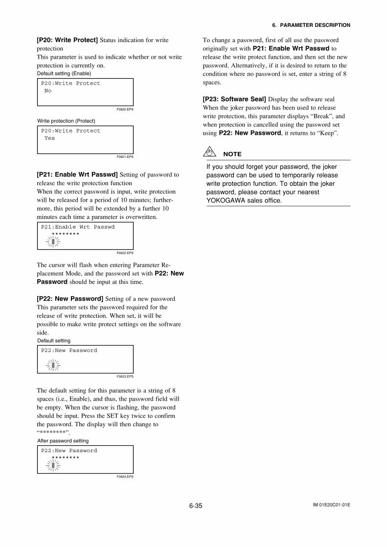
IM 01E20C01-01E6-35
6. PARAMETER DESCRIPTION
[P20: Write Protect] Status indication for writeprotectionThis parameter is used to indicate whether or not writeprotection is currently on.
F0620.EPS
Default setting (Enable)
P20:Write Protect No
P20:Write Protect Yes
F0621.EPS
Write protection (Protect)
[P21: Enable Wrt Passwd] Setting of password torelease the write protection functionWhen the correct password is input, write protectionwill be released for a period of 10 minutes; further-more, this period will be extended by a further 10minutes each time a parameter is overwritten.
P21:Enable Wrt Passwd ********
F0622.EPS
The cursor will flash when entering Parameter Re-placement Mode, and the password set with P22: NewPassword should be input at this time.
[P22: New Password] Setting of a new passwordThis parameter sets the password required for therelease of write protection. When set, it will bepossible to make write protect settings on the softwareside.
P22:New Password
F0623.EPS
Default setting
The default setting for this parameter is a string of 8spaces (i.e., Enable), and thus, the password field willbe empty. When the cursor is flashing, the passwordshould be input. Press the SET key twice to confirmthe password. The display will then change to“********”.
P22:New Password ********
F0624.EPS
After password setting
To change a password, first of all use the passwordoriginally set with P21: Enable Wrt Passwd torelease the write protect function, and then set the newpassword. Alternatively, if it is desired to return to thecondition where no password is set, enter a string of 8spaces.
[P23: Software Seal] Display the software sealWhen the joker password has been used to releasewrite protection, this parameter displays “Break”, andwhen protection is cancelled using the password setusing P22: New Password, it returns to “Keep”.
NOTE
If you should forget your password, the jokerpassword can be used to temporarily releasewrite protection function. To obtain the jokerpassword, please contact your nearestYOKOGAWA sales office.
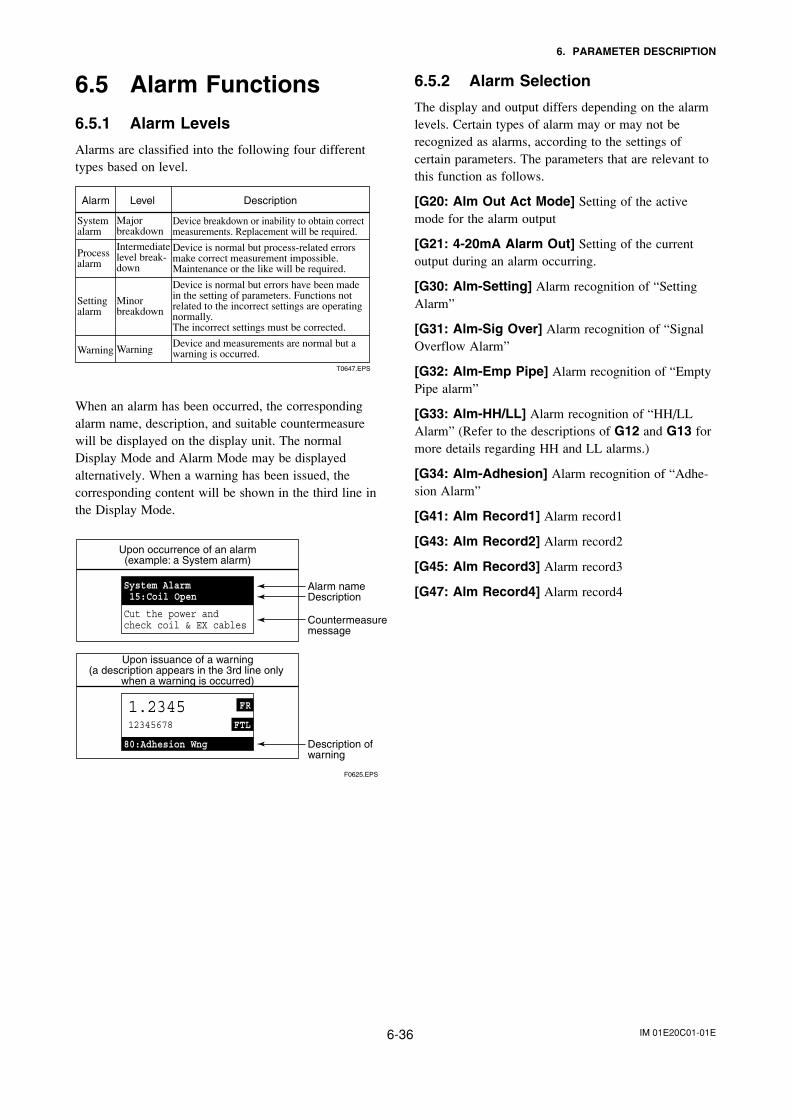
IM 01E20C01-01E6-36
6. PARAMETER DESCRIPTION
6.5 Alarm Functions
6.5.1 Alarm Levels
Alarms are classified into the following four differenttypes based on level.
Intermediate level break-down
Major breakdown
Alarm DescriptionLevel
Warning
Setting alarm
Process alarm
System alarm
Device breakdown or inability to obtain correct measurements. Replacement will be required. Device is normal but process-related errors make correct measurement impossible. Maintenance or the like will be required. Device is normal but errors have been made in the setting of parameters. Functions not related to the incorrect settings are operating normally. The incorrect settings must be corrected. Device and measurements are normal but a warning is occurred.
T0647.EPS
Warning
Minor breakdown
When an alarm has been occurred, the correspondingalarm name, description, and suitable countermeasurewill be displayed on the display unit. The normalDisplay Mode and Alarm Mode may be displayedalternatively. When a warning has been issued, thecorresponding content will be shown in the third line inthe Display Mode.
Upon occurrence of an alarm(example: a System alarm)
Upon issuance of a warning(a description appears in the 3rd line only
when a warning is occurred)
Alarm nameDescription
Countermeasuremessage
Description of warning
F0625.EPS
6.5.2 Alarm Selection
The display and output differs depending on the alarmlevels. Certain types of alarm may or may not berecognized as alarms, according to the settings ofcertain parameters. The parameters that are relevant tothis function as follows.
[G20: Alm Out Act Mode] Setting of the activemode for the alarm output
[G21: 4-20mA Alarm Out] Setting of the currentoutput during an alarm occurring.
[G30: Alm-Setting] Alarm recognition of “SettingAlarm”
[G31: Alm-Sig Over] Alarm recognition of “SignalOverflow Alarm”
[G32: Alm-Emp Pipe] Alarm recognition of “EmptyPipe alarm”
[G33: Alm-HH/LL] Alarm recognition of “HH/LLAlarm” (Refer to the descriptions of G12 and G13 formore details regarding HH and LL alarms.)
[G34: Alm-Adhesion] Alarm recognition of “Adhe-sion Alarm”
[G41: Alm Record1] Alarm record1
[G43: Alm Record2] Alarm record2
[G45: Alm Record3] Alarm record3
[G47: Alm Record4] Alarm record4
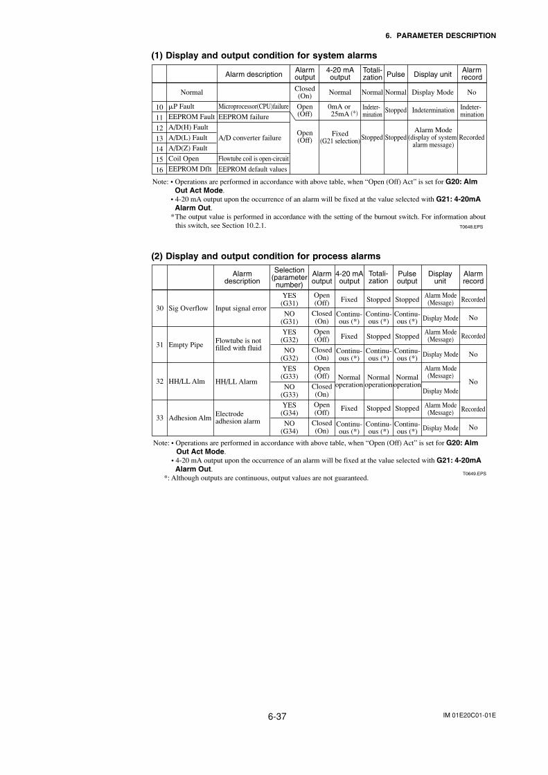
IM 01E20C01-01E6-37
6. PARAMETER DESCRIPTION
(1) Display and output condition for system alarms
Alarm descriptionAlarmoutput
4-20 mAoutput
Totali-zation Pulse Display unit
Alarmrecord
Normal Normal Normal Normal Display Mode NoClosed(On)
P Fault
EEPROM Fault
A/D(H) Fault
A/D(L) Fault
A/D(Z) Fault
Coil Open
EEPROM Dflt
Microprocessor(CPU)failure
EEPROM failure
A/D converter failure
Flowtube coil is open-circuit
EEPROM default values
Open(Off)
Fixed(G21 selection) Stopped Stopped Recorded
Alarm Mode(display of system
alarm message)
Open(Off)
0mA or 25mA Stopped Indetermination10
11
12
13
14
15
16
T0648.EPS
Note: • Operations are performed in accordance with above table, when “Open (Off) Act” is set for G20: Alm Out Act Mode.
• 4-20 mA output upon the occurrence of an alarm will be fixed at the value selected with G21: 4-20mA Alarm Out.
*The output value is performed in accordance with the setting of the burnout switch. For information about this switch, see Section 10.2.1.
Indeter-mination
Indeter-mination(*)
(2) Display and output condition for process alarms
Alarmdescription
Selection(parameter
number)
Alarmoutput
4-20 mAoutput
Totali-zation
Pulseoutput
Displayunit
Alarmrecord
30
31
32
33
Sig Overflow
Empty Pipe
HH/LL Alm
Adhesion Alm
Input signal error
Flowtube is notfilled with fluid
HH/LL Alarm
Electrode adhesion alarm
T0649.EPS
Alarm Mode(Message)
Alarm Mode(Message)
Alarm Mode(Message)
Alarm Mode(Message)
Display Mode
Display Mode
Display Mode
Display Mode
Fixed
Continu-ous (*)
Continu-ous (*)
Continu-ous (*)
Fixed
Stopped
Continu-ous (*)
Continu-ous (*)
Continu-ous (*)
Stopped
Stopped
Continu-ous (*)
Continu-ous (*)
Continu-ous (*)
Stopped
Normaloperation
Normaloperation
Normaloperation
Fixed Stopped Stopped
Recorded
No
Recorded
No
No
Recorded
No
Open(Off)
Closed(On)
Open(Off)
Closed(On)
Open(Off)
Closed(On)
Open(Off)
Closed(On)
YES(G31)
NO(G31)
YES(G32)
NO(G32)
YES(G33)
NO(G33)
YES(G34)
NO(G34)
Note: • Operations are performed in accordance with above table, when “Open (Off) Act” is set for G20: Alm Out Act Mode.
• 4-20 mA output upon the occurrence of an alarm will be fixed at the value selected with G21: 4-20mA Alarm Out.
*: Although outputs are continuous, output values are not guaranteed.
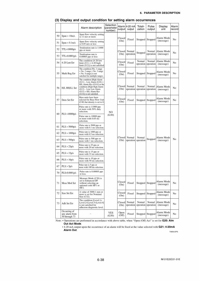
IM 01E20C01-01E6-38
6. PARAMETER DESCRIPTION
(3) Display and output condition for setting alarm occurrences
50 Span > 10m/s
51 Span < 0.1m/s
52 TTL>10000p/s
53 TTL<0.0001p/s
54 4-20 Lmt Err
55 Multi Rng Err
56 H/L HH/LL Set
57 Dens Set Err
60 PLS >10000p/s
61 PLS > 5000p/s
62 PLS > 1000p/s
63 PLS > 500p/s
64 PLS > 25p/s
65 PLS > 15p/s
66 PLS > 10p/s
67 PLS > 5p/s
70 PLS<0.0001p/s
71 Meas Mod Set
72 Size Set Err
Closed(On)
Closed(On)
Closed(On)
Closed(On)
Closed(On)
Closed(On)
Closed(On)
Closed(On)
Closed(On)
Closed(On)
Fixed Stopped StoppedAlarm Mode
(message) No
Normaloperation Stopped
Normaloperation
Alarm Mode(message) No
FixedNormal
operationNormal
operationAlarm Mode
(message) No
Fixed Stopped StoppedAlarm Mode
(message) No
Normaloperation
Normaloperation
Normaloperation No
Fixed Stopped StoppedAlarm Mode
(message)
Alarm Mode(message)
No
Normaloperation
Normaloperation
Normaloperation
Normaloperation
Normaloperation Stopped
Alarm Mode(message) No
Fixed Stopped StoppedAlarm Mode
(message) No
Fixed Stopped StoppedAlarm Mode
(message) No
Open(Off) Fixed Stopped Stopped
Alarm Mode(message) No
NO(G30)
YES(G30)
Note: • Operations are performed in accordance with above table, when “Open (Off) Act” is set for G20: Alm Out Act Mode.
• 4-20 mA output upon the occurrence of an alarm will be fixed at the value selected with G21: 4-20mA Alarm Out.
T0650.EPS
AlarmrecordAlarm description
Selection(parameter
number)
Alarmoutput
4-20 mAoutput
Totali-zation
Pulseoutput
Displayunit
Occurring of any alarm from 50 through 73
–
Span flow velocity setting is 11 m/s or more
Span flow velocity setting is 0.05 m/s or less
Totalization rate is 11000 pps or more
Totalization rate is 0.00005 pps or less
The condition [4-20 low limit (J11) < 4-20 high limit (J12)] is not satisfied.
The condition [No. 1 range < No. 2 range < No. 3 range < No. 4 range] is not satisfied for multiple ranges.
The condition [High Alarm (G11) – Low Alarm (G10) > H/L Alarm Hys (G14)] or the condition [High High Alarm (G13) – Low Low Alarm (G12) > H/L Alarm Hys (G14)] is not satisfied.
Mass units have been selected for Base Flow Unit (C40) but density is set to 0.
Pulse rate is 11000 pps or more with 50% dutyselection.
Pulse rate is 10000 pps or more with 0.05 ms selection.
Pulse rate is 5000 pps or more with 0.1 ms selection.
Pulse rate is 1000 pps or more with 0.5 ms selection.
Pulse rate is 500 pps or more with 1 ms selection.
Pulse rate is 25 pps or more with 20 ms selection.
Pulse rate is 15 pps or more with 33 ms selection.
Pulse rate is 10 pps or more with 50 ms selection.
Pulse rate is 5 pps or more with 100 ms selection.
Pulse rate is 0.00005 pps or less.
Measure Mode (C20) is set to Enhanced DF without selecting an optional code HF1 or HF2.
A value of 3000.1 mm or more is set for Nominal Size (C32).
73 Adh Set Err Alarm Mode(message) No
The condition [Level:1<Level:2<Level:3<Level:4]is not satisfied for adhesion diagnostic level.
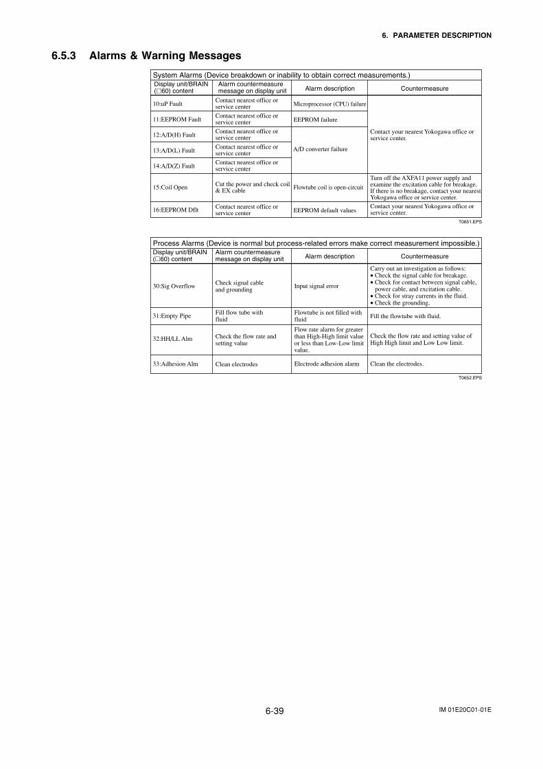
IM 01E20C01-01E6-39
6. PARAMETER DESCRIPTION
6.5.3 Alarms & Warning Messages
System Alarms (Device breakdown or inability to obtain correct measurements.)Display unit/BRAIN(60) content
Alarm countermeasuremessage on display unit
10:uP FaultContact nearest office or service center Microprocessor (CPU) failure
11:EEPROM FaultContact nearest office or service center EEPROM failure
12:A/D(H) FaultContact nearest office or service center
A/D converter failure 13:A/D(L) FaultContact nearest office or service center
14:A/D(Z) FaultContact nearest office or service center
15:Coil Open Cut the power and check coil & EX cable Flowtube coil is open-circuit
16:EEPROM Dflt Contact nearest office or service center EEPROM default values
Contact your nearest Yokogawa office or service center.
Turn off the AXFA11 power supply and examine the excitation cable for breakage. If there is no breakage, contact your nearest Yokogawa office or service center.Contact your nearest Yokogawa office or service center.
Alarm description Countermeasure
T0651.EPS
Process Alarms (Device is normal but process-related errors make correct measurement impossible.)Display unit/BRAIN(60) content
Alarm countermeasure message on display unit
30:Sig Overflow Check signal cable and grounding
Input signal error
31:Empty Pipe Fill flow tube with fluid
Flowtube is not filled withfluid
Carry out an investigation as follows:• Check the signal cable for breakage.• Check for contact between signal cable,
power cable, and excitation cable.• Check for stray currents in the fluid.• Check the grounding.
Fill the flowtube with fluid.
33:Adhesion Alm Clean electrodes Electrode adhesion alarm Clean the electrodes.
32:HH/LL Alm Check the flow rate and setting value
Flow rate alarm for greater than High-High limit valueor less than Low-Low limitvalue.
Check the flow rate and setting value of High High limit and Low Low limit.
Alarm description Countermeasure
T0652.EPS
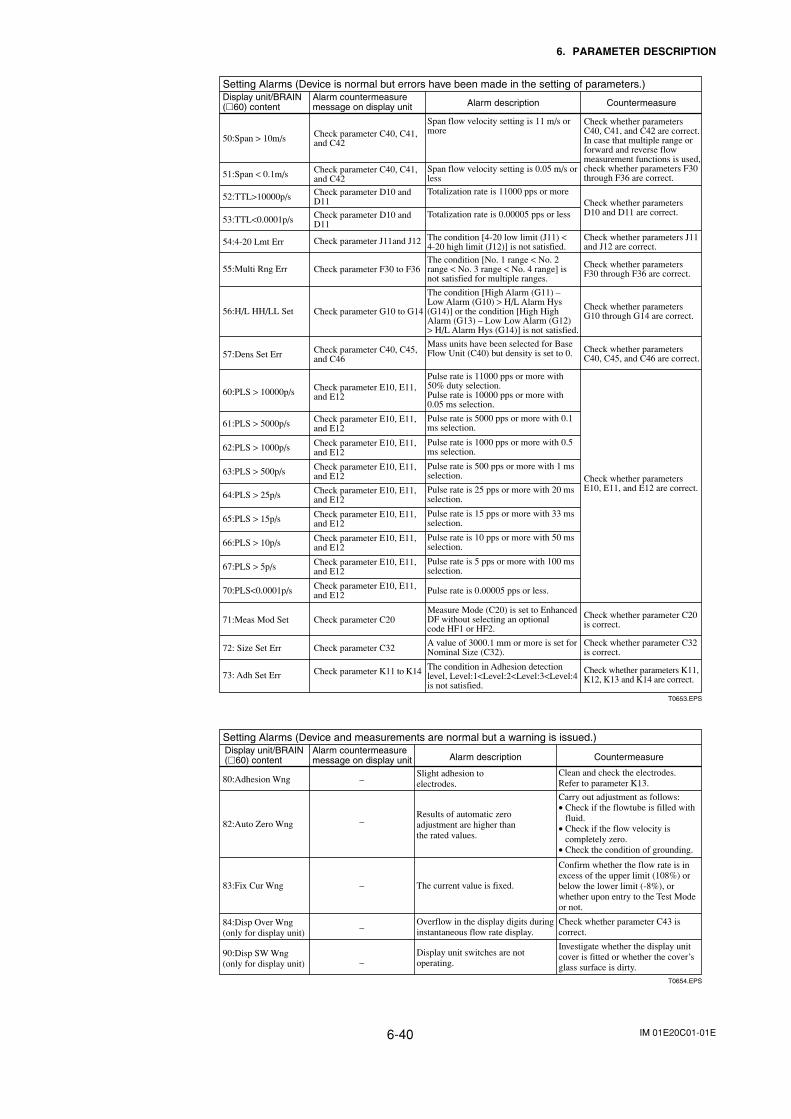
IM 01E20C01-01E6-40
6. PARAMETER DESCRIPTION
Setting Alarms (Device is normal but errors have been made in the setting of parameters.)Display unit/BRAIN (60) content
Alarm countermeasure message on display unit
50:Span > 10m/s Check parameter C40, C41, and C42
Span flow velocity setting is 11 m/s or more
51:Span < 0.1m/s Check parameter C40, C41, and C42
Span flow velocity setting is 0.05 m/s or less
52:TTL>10000p/s Check parameter D10 and D11
Totalization rate is 11000 pps or more
53:TTL<0.0001p/s Check parameter D10 and D11
Totalization rate is 0.00005 pps or less
Check whether parameters C40, C41, and C42 are correct.In case that multiple range or forward and reverse flow measurement functions is used,check whether parameters F30through F36 are correct.
Check whether parameters D10 and D11 are correct.
54:4-20 Lmt Err Check parameter J11and J12 The condition [4-20 low limit (J11) < 4-20 high limit (J12)] is not satisfied.
Check whether parameters J11 and J12 are correct.
55:Multi Rng Err Check parameter F30 to F36The condition [No. 1 range < No. 2 range < No. 3 range < No. 4 range] is not satisfied for multiple ranges.
Check whether parameters F30 through F36 are correct.
56:H/L HH/LL Set Check parameter G10 to G14
The condition [High Alarm (G11) – Low Alarm (G10) > H/L Alarm Hys (G14)] or the condition [High High Alarm (G13) – Low Low Alarm (G12) > H/L Alarm Hys (G14)] is not satisfied.
Check whether parameters G10 through G14 are correct.
57:Dens Set Err Check parameter C40, C45, and C46
Mass units have been selected for Base Flow Unit (C40) but density is set to 0. Check whether parameters
C40, C45, and C46 are correct.
60:PLS > 10000p/s Check parameter E10, E11, and E12
Pulse rate is 11000 pps or more with 50% duty selection.Pulse rate is 10000 pps or more with 0.05 ms selection.
61:PLS > 5000p/s Check parameter E10, E11, and E12
Pulse rate is 5000 pps or more with 0.1 ms selection.
62:PLS > 1000p/s Check parameter E10, E11, and E12
Pulse rate is 1000 pps or more with 0.5 ms selection.
63:PLS > 500p/s Check parameter E10, E11, and E12
Pulse rate is 500 pps or more with 1 ms selection.
64:PLS > 25p/s Check parameter E10, E11, and E12
Pulse rate is 25 pps or more with 20 ms selection.
65:PLS > 15p/s Check parameter E10, E11, and E12
Pulse rate is 15 pps or more with 33 ms selection.
66:PLS > 10p/s Check parameter E10, E11, and E12
Pulse rate is 10 pps or more with 50 ms selection.
67:PLS > 5p/s Check parameter E10, E11, and E12
Pulse rate is 5 pps or more with 100 ms selection.
70:PLS<0.0001p/s Check parameter E10, E11, and E12 Pulse rate is 0.00005 pps or less.
71:Meas Mod Set Check parameter C20Measure Mode (C20) is set to Enhanced DF without selecting an optional code HF1 or HF2.
Check whether parameters E10, E11, and E12 are correct.
Check whether parameter C20 is correct.
72: Size Set Err Check parameter C32A value of 3000.1 mm or more is set for Nominal Size (C32).
Check whether parameter C32 is correct.
73: Adh Set Err Check parameter K11 to K14 The condition in Adhesion detection level, Level:1<Level:2<Level:3<Level:4is not satisfied.
Check whether parameters K11,K12, K13 and K14 are correct.
Alarm description Countermeasure
T0653.EPS
Setting Alarms (Device and measurements are normal but a warning is issued.)Display unit/BRAIN (60) content
Alarm countermeasure message on display unit
80:Adhesion Wng –Slight adhesion to electrodes.
Clean and check the electrodes.Refer to parameter K13.
82:Auto Zero Wng –Results of automatic zero adjustment are higher than the rated values.
Carry out adjustment as follows:• Check if the flowtube is filled with
fluid.• Check if the flow velocity is
completely zero. • Check the condition of grounding.
83:Fix Cur Wng – The current value is fixed.
Confirm whether the flow rate is in excess of the upper limit (108%) or below the lower limit (-8%), or whether upon entry to the Test Mode or not.
90:Disp SW Wng(only for display unit) –
Display unit switches are not operating.
Investigate whether the display unit cover is fitted or whether the cover’s glass surface is dirty.
84:Disp Over Wng(only for display unit)
–Overflow in the display digits during instantaneous flow rate display.
Check whether parameter C43 is correct.
Alarm description Countermeasure
T0654.EPS
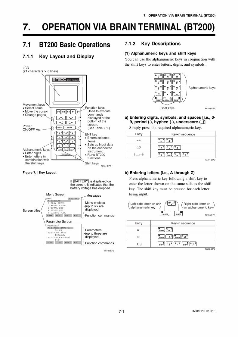
IM 01E20C01-01E7-1
7. OPERATION VIA BRAIN TERMINAL (BT200)
7. OPERATION VIA BRAIN TERMINAL (BT200)
7.1 BT200 Basic Operations
7.1.1 Key Layout and Display
F0701.EPS
LCD (21 characters 8 lines)
Power ON/OFF key
ENT key• Enters selected
items• Sets up input data
on the connected instrument.
• Runs BT200 functions.
Alphanumeric keys• Enter digits• Enter letters in
combination with the shift keys. Shift keys
Function keysUsed to execute commands displayed at the bottom of the screen.(See Table 7.1.)
Movement keys• Select items• Move the cursor• Change pages
Figure 7.1 Key Layout
F0702.EPS
PARAMETER A10:FLOW RATE(%) 80.0% A20:FLOW RATE 100m3/h A21:FLW RATE(mA) 1417
Menu choices (up to six are displayed)
MessagesMenu Screen
Screen titles
MENU A:DISPLAY B:EASY SETUP C:BASIC SETUP D:TOTAL SET E:PULSE SET F:STATUS FUNC
BATTERY
HOME SET ADJ ESC Function commands
Parameter Screen
DATA DIAG PRNT ESC
Parameters (up to three are displayed)
Function commands
If BATTERY is displayed on the screen, it indicates that the battery voltage has dropped.
7.1.2 Key Descriptions
(1) Alphanumeric keys and shift keysYou can use the alphanumeric keys in conjunction withthe shift keys to enter letters, digits, and symbols.
Shift keys
Alphanumeric keys
F0703.EPS
a) Entering digits, symbols, and spaces [i.e., 0-9, period (.), hyphen (-), underscore (_)]Simply press the required alphanumeric key.
1 –9
Entry Key-in sequence
– 4
0.3
T0701.EPS
b) Entering letters (i.e., A through Z)Press alphanumeric key following a shift key toenter the letter shown on the same side as the shiftkey. The shift key must be pressed for each letterbeing input.
Left-side letter on an alphanumeric key
F0704.EPS
Right-side letter on an alphanumeric key
Entry Key-in sequence
W
IC
J. BT0702.EPS
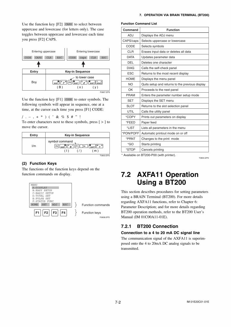
IM 01E20C01-01E7-2
7. OPERATION VIA BRAIN TERMINAL (BT200)
Use the function key [F2] CAPS to select betweenuppercase and lowercase (for letters only). The casetoggles between uppercase and lowercase each timeyou press [F2] CAPS.
Entry
Boy
Key-in Sequence
F0807.EPS
CODE CAPS CLR ESC
Entering uppercase
CODE caps CLR ESC
Entering lowercase
( B ) ( y )( o )
to lower case
Use the function key [F1] CODE to enter symbols. Thefollowing symbols will appear in sequence, one at atime, at the cursor each time you press [F1] CODE:
/ . – , + * ) ( ’ & % $ # ” !To enter characters next to these symbols, press [ > ] tomove the cursor.
( / )
Entry
l/m
Key-in Sequence
T0803.EPS
( m )( I )
symbol command
(2) Function KeysThe functions of the function keys depend on thefunction commands on display.
Function commands
Function keysF0808.EPS
MENU A:DISPLAY B:EASY SETUP C:BASIC SETUP D:TOTAL SET E:PULSE SET F:STATUS FUNCHOME SET ADJ ESC
Function Command List
Command Function
ADJ Displays the ADJ menu
Selects uppercase or lowercase
Selects symbols
Erases input data or deletes all data
Updates parameter data
Deletes one character
Calls the self-check panel
Returns to the most recent display
Displays the menu panel
Quits setup and returns to the previous display
Proceeds to the next panel
Enters the parameter number setup mode
Displays the SET menu
Returns to the slot selection panel
Calls the utility panel
Prints out parameters on display
Paper feed
Lists all parameters in the menu
Automatic printout mode on or off
Changes to the print mode
Starts printing
Cancels printing
CAPS/caps
CODE
CLR
DATA
DEL
DIAG
ESC
HOME
NO
OK
PRAM
SET
SLOT
UTIL
*COPY
*FEED
*LIST
*PON/POFF
*PRNT
*GO
*STOP
* Available on BT200-P00 (with printer).T0804.EPS
7.2 AXFA11 OperationUsing a BT200
This section describes procedures for setting parametersusing a BRAIN Terminal (BT200). For more detailsregarding AXFA11 functions, refer to Chapter 6:Parameter Description; and for more details regardingBT200 operation methods, refer to the BT200 User’sManual (IM 01C00A11-01E).
7.2.1 BT200 ConnectionConnection to a 4 to 20 mA DC signal lineThe communication signal of the AXFA11 is superim-posed onto the 4 to 20mA DC analog signals to betransmitted.
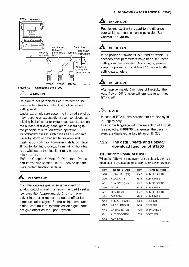
IM 01E20C01-01E7-3
7. OPERATION VIA BRAIN TERMINAL (BT200)
AXFA11 terminals
BT200 BT200 BT200
Relaying terminals
4 to 20mA DC signal transmission line
Control room
Receiving resistance: 250 to 450
Receiving instrumentTerminal
board
F0705.EPS
I
I
Figure 7.2 Connecting the BT200
WARNING
Be sure to set parameters as "Protect" on thewrite protect function after finish of parametersetting work.Under extremely rare case, the infra-red switchesmay respond unexpectedly in such conditions assticking ball of water or extraneous substances onthe surface of display panel glass according tothe principle of infra-red switch operation.Its probability rises in such cases as sticking rainwater by storm or other similar situation andwashing up work near flowmeter installation place.Either to illuminate or stop illuminating the infra-red switches by the flashlight may cause themis-reaction.Refer to Chapter 6 "Menu P: Parameter Protec-tion Items" and section "10.2.3" how to use thewrite protect function in detail.
IMPORTANT
Communication signal is superimposed onanalog output signal. It is recommended to set alow-pass flter (approximately 0.1s) to the re-ceiver in order to reduce the output effect fromcommunication signal. Before online-communi-cation, confirm that communication signal doesnot give effect on the upper system.
IMPORTANT
Restrictions exist with regard to the distanceover which communication is possible. (SeeChapter 11: Outline.)
IMPORTANT
If the power of flowmeter is turned off within 30seconds after parameters have been set, thesesettings will be canceled. Accordingly, pleasekeep the power on for at least 30 seconds aftersetting parameters.
IMPORTANT
After approximately 5 minutes of inactivity, theAuto Power-Off function will operate to turn yourBT200 off.
NOTE
In case of BT200, the parameters are displayedin English only.Even if the language with the exception of Englishis selected at B10/H30: Language, the param-eters are displayed in English upon BT200.
7.2.2 The data update and upload/download function of BT200
(1) The data update of BT200When the following parameters are displayed, the mea-sured data is updated automatically every seven seconds.
T0703.EPS
Item
A10
A20
A21
A30
A31
A32
C44
G22
G40
G41
G42
Name (BRAIN)
FLOW RATE (%)
FLOW RATE
FLW RATE (mA)
TOTAL
REV TOTAL
DIF TOTAL
VELOCITY CHK
4-20 BURNOUT
OPERATE TIME
ALM RECORD1
ALM TIME 1
Item
G43
G44
G45
G46
G47
G48
N23
N24
P20
P23
Name (BRAIN)
ALM RECORD2
ALM TIME 2
ALM RECORD3
ALM TIME 3
ALM RECORD4
ALM TIME 4
TEST SI1
TEST SI2
W PROTECT
SOFT SEAL
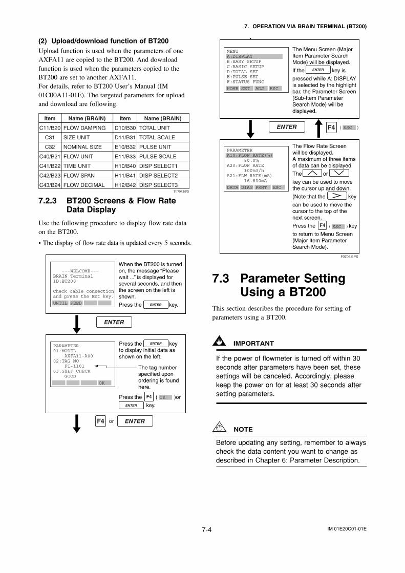
IM 01E20C01-01E7-4
7. OPERATION VIA BRAIN TERMINAL (BT200)
(2) Upload/download function of BT200Upload function is used when the parameters of oneAXFA11 are copied to the BT200. And downloadfunction is used when the parameters copied to theBT200 are set to another AXFA11.For details, refer to BT200 User’s Manual (IM01C00A11-01E). The targeted parameters for uploadand download are following.
T0704.EPS
Item
C11/B20
C31
C32
C40/B21
C41/B22
C42/B23
C43/B24
Item
D10/B30
D11/B31
E10/B32
E11/B33
H10/B40
H11/B41
H12/B42
Name (BRAIN)
FLOW DAMPING
SIZE UNIT
NOMINAL SIZE
FLOW UNIT
TIME UNIT
FLOW SPAN
FLOW DECIMAL
Name (BRAIN)
TOTAL UNIT
TOTAL SCALE
PULSE UNIT
PULSE SCALE
DISP SELECT1
DISP SELECT2
DISP SELECT3
7.2.3 BT200 Screens & Flow RateData Display
Use the following procedure to display flow rate dataon the BT200.
• The display of flow rate data is updated every 5 seconds.
When the BT200 is turned on, the message “Please wait ...” is displayed for several seconds, and then the screen on the left is shown.
Press the key.
or
Press the key to display initial data as shown on the left.
Press the ( )or
key.
The tag number specified upon ordering is found here.
–––WELCOME–––BRAIN TerminalID:BT200 Check cable connectionand press the Ent key.
UNTIL FEED
PARAMETER01:MODEL AXFA11-A0002:TAG NO FI-110103:SELF CHECK GOOD
OK
OK
The Flow Rate Screen will be displayed.A maximum of three items of data can be displayed.
The or
key can be used to movethe cursor up and down.
(Note that the key
can be used to move the cursor to the top of the next screen.
Press the ( ) key
to return to Menu Screen (Major Item ParameterSearch Mode).
F0706.EPS
( )
The Menu Screen (MajorItem Parameter SearchMode) will be displayed.
If the key is
pressed while A: DISPLAYis selected by the highlightbar, the Parameter Screen(Sub-Item Parameter Search Mode) will be displayed.
MENUA:DISPLAYB:EASY SETUPC:BASIC SETUPD:TOTAL SETE:PULSE SETF:STATUS FUNC
HOME SET ADJ ESC
PARAMETERA10:FLOW RATE(%) 80.0%A20:FLOW RATE 100m3/hA21:FLW RATE(mA) 16.800mA
DATA DIAG PRNT ESC
ESC
ESC
7.3 Parameter SettingUsing a BT200
This section describes the procedure for setting ofparameters using a BT200.
IMPORTANT
If the power of flowmeter is turned off within 30seconds after parameters have been set, thesesettings will be canceled. Accordingly, pleasekeep the power on for at least 30 seconds aftersetting parameters.
NOTE
Before updating any setting, remember to alwayscheck the data content you want to change asdescribed in Chapter 6: Parameter Description.
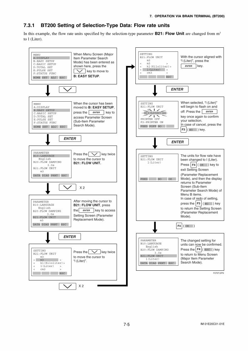
IM 01E20C01-01E7-5
7. OPERATION VIA BRAIN TERMINAL (BT200)
7.3.1 BT200 Setting of Selection-Type Data: Flow rate units
In this example, the flow rate units specified by the selection-type parameter B21: Flow Unit are changed from m3
to l (Liter).
With the cursor aligned with “l (Liter)”, press the
key.
X 2
X 2
MENUA:DISPLAYB:EASY SETUPC:BASIC SETUPD:TOTAL SETE:PULSE SETF:STATUS FUNC
HOME SET ADJ ESC
MENUA:DISPLAYB:EASY SETUPC:BASIC SETUPD:TOTAL SETE:PULSE SETF:STATUS FUNC
HOME SET ADJ ESC
PARAMETERB10:LANGUAGE EnglishB20:FLOW DAMPING 3.0sB21:FLOW UNIT m3
DATA DIAG PRNT ESC
PARAMETERB10:LANGUAGE EnglishB20:FLOW DAMPING 3.0sB21:FLOW UNIT m3
DATA DIAG PRNT ESC
SETTINGB21:FLOW UNIT l(Liter)
FEED NO OK
SETTINGB21:FLOW UNIT m3< m3 >< kl(Kiloliter)>< l(Liter) >< cm3 >
ESC
SETTINGB21:FLOW UNIT m3< m3 >< kl(Kiloliter)>< l(Liter) >< cm3 >
ESC
SETTINGB21:FLOW UNIT m3 l(Liter)
PRINTER OFFF2:PRINTER ON
FEED POFF NO
The changed setting for units can now be confirmed.
Press the ( ) key
to return to Menu Screen (Major Item Parameter Search Mode).
When Menu Screen (Major Item Parameter Search Mode) has been entered as shown here, press the
key to move to
B: EASY SETUP.
When the cursor has been moved to B: EASY SETUP,
press the key to
access Parameter Screen(Sub-Item Parameter Search Mode).
Press the key twice
to move the cursor to B21: FLOW UNIT.
Press the key twice
to move the cursor to “l (Liter)”.
( )OK
F0707.EPS
PARAMETERB10:LANGUAGE EnglishB20:FLOW DAMPING 3.0s B21:FLOW UNIT l(Liter)
DATA DIAG PRNT ESC
The units for flow rate have been changed to l (Liter).
Press ( ) key to
exit Setting Screen
(Parameter Replacement Mode), and then the display returns to Parameter Screen (Sub-Item Parameter Search Mode) of Menu B items.In case of redo of setting,
press the ( ) key
to return the Setting Screen (Parameter Replacement Mode).
OK
NO
When selected, “l (Liter)” will begin to flash on and
off: Press the
key once again to confirm your selection.In case of cancel, press the
( ) key. NO
After moving the cursor to B21: FLOW UNIT, press
the key to access
Setting Screen (ParameterReplacement Mode).
ESC
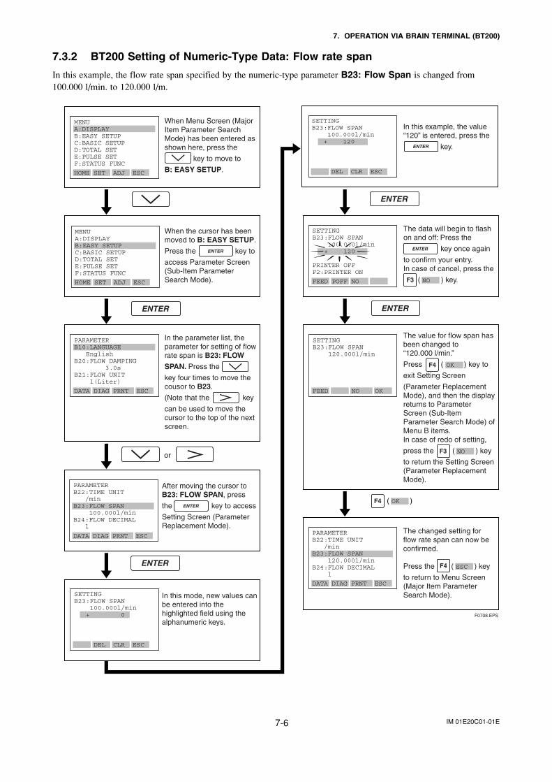
IM 01E20C01-01E7-6
7. OPERATION VIA BRAIN TERMINAL (BT200)
7.3.2 BT200 Setting of Numeric-Type Data: Flow rate span
In this example, the flow rate span specified by the numeric-type parameter B23: Flow Span is changed from100.000 l/min. to 120.000 l/m.
or
In this mode, new values can be entered into the highlighted field using the alphanumeric keys.
In this example, the value “120” is entered, press the
key.
F0708.EPS
MENUA:DISPLAYB:EASY SETUPC:BASIC SETUPD:TOTAL SETE:PULSE SETF:STATUS FUNC
HOME SET ADJ ESC
MENUA:DISPLAYB:EASY SETUPC:BASIC SETUPD:TOTAL SETE:PULSE SETF:STATUS FUNC
HOME SET ADJ ESC
PARAMETERB10:LANGUAGE EnglishB20:FLOW DAMPING 3.0sB21:FLOW UNIT l(Liter)
DATA DIAG PRNT ESC
PARAMETERB22:TIME UNIT /minB23:FLOW SPAN 100.000l/minB24:FLOW DECIMAL l
DATA DIAG PRNT ESC
SETTINGB23:FLOW SPAN 120.000l/min
FEED NO OK
PARAMETERB22:TIME UNIT /minB23:FLOW SPAN 120.000l/minB24:FLOW DECIMAL l
DATA DIAG PRNT ESC
SETTINGB23:FLOW SPAN 100.000l/min + 0
DEL CLR ESC
SETTINGB23:FLOW SPAN 100.000l/min + 120
DEL CLR ESC
SETTINGB23:FLOW SPAN 100.000l/min + 120
PRINTER OFFF2:PRINTER ON
FEED POFF NO
After moving the cursor to B23: FLOW SPAN, press
the key to access
Setting Screen (Parameter Replacement Mode).
When Menu Screen (Major Item Parameter Search Mode) has been entered as shown here, press the
key to move to
B: EASY SETUP.
When the cursor has beenmoved to B: EASY SETUP.
Press the key to
access Parameter Screen (Sub-Item Parameter Search Mode).
The data will begin to flash on and off: Press the
key once again
to confirm your entry.In case of cancel, press the
( ) key.NO
The changed setting for flow rate span can now be confirmed.
Press the ( ) key
to return to Menu Screen (Major Item Parameter Search Mode).
ESC
In the parameter list, the parameter for setting of flow rate span is B23: FLOW
SPAN. Press the
key four times to move the cousor to B23.
(Note that the key
can be used to move the cursor to the top of the next screen.
The value for flow span has been changed to “120.000 l/min.”
Press ( ) key to
exit Setting Screen
(Parameter Replacement Mode), and then the display returns to Parameter Screen (Sub-Item Parameter Search Mode) of Menu B items.In case of redo of setting,
press the ( ) key
to return the Setting Screen (Parameter Replacement Mode).
OK
NO
( )OK
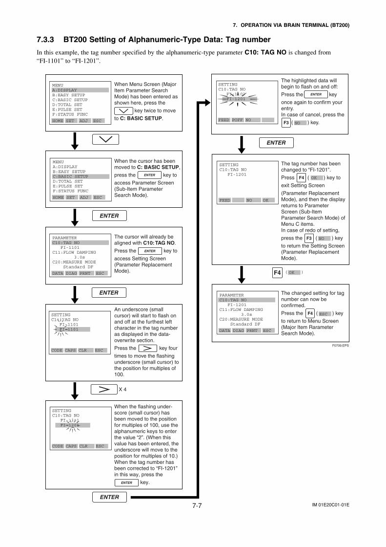
IM 01E20C01-01E7-7
7. OPERATION VIA BRAIN TERMINAL (BT200)
7.3.3 BT200 Setting of Alphanumeric-Type Data: Tag number
In this example, the tag number specified by the alphanumeric-type parameter C10: TAG NO is changed from“FI-1101” to “FI-1201”.
The highlighted data will begin to flash on and off:
Press the key
once again to confirm your entry.In case of cancel, press the
( ) key.
F0709.EPS
X 4
When the flashing under-score (small cursor) has been moved to the position for multiples of 100, use the alphanumeric keys to enter the value “2”. (When this value has been entered, the underscore will move to the position for multiples of 10.)When the tag number has been corrected to “FI-1201” in this way, press the
key.
MENUA:DISPLAYB:EASY SETUPC:BASIC SETUPD:TOTAL SETE:PULSE SETF:STATUS FUNC
HOME SET ADJ ESC
MENUA:DISPLAYB:EASY SETUPC:BASIC SETUPD:TOTAL SETE:PULSE SETF:STATUS FUNC
HOME SET ADJ ESC
PARAMETERC10:TAG NO FI-1101C11:FLOW DAMPING 3.0sC20:MEASURE MODE Standard DF
DATA DIAG PRNT ESC
SETTINGC10:TAG NO FI-1201
FEED NO OK
SETTINGC10:TAG NO FI-1101 FI-1101
CODE CAPS CLR ESC
SETTINGC10:TAG NO FI-1101 FI-1201
CODE CAPS CLR ESC
SETTINGC10:TAG NO FI-1101 FI-1201
FEED POFF NO
PARAMETERC10:TAG NO FI-1201C11:FLOW DAMPING 3.0s C20:MEASURE MODE Standard DF
DATA DIAG PRNT ESC
OK( )
An underscore (small cursor) will start to flash on and off at the furthest left character in the tag number as displayed in the data-overwrite section.
Press the key four
times to move the flashing underscore (small cursor) to the position for multiples of 100.
When the cursor has been moved to C: BASIC SETUP,
press the key to
access Parameter Screen (Sub-Item Parameter Search Mode).
When Menu Screen (Major Item Parameter Search Mode) has been entered asshown here, press the
key twice to move
to C: BASIC SETUP.
The changed setting for tag number can now be confirmed.
Press the ( ) key
to return to Menu Screen (Major Item Rarameter Search Mode).
ESC
The cursor will already be aligned with C10: TAG NO.
Press the key to
access Setting Screen (Parameter Replacement Mode).
NO
The tag number has been changed to “FI-1201”.
Press ( ) key to
exit Setting Screen
(Parameter Replacement Mode), and then the display returns to Parameter Screen (Sub-Item Parameter Search Mode) of Menu C items.In case of redo of setting,
press the ( ) key
to return the Setting Screen (Parameter Replacement Mode).
OK
NO
IM 01E20C01-01E8-1
8. OPERATION VIA HART COMMUNICATOR TOOL (HART 5)
NOTE
This chapter describes the AXFA11 as anexample.
Note: HART is a registered trademark of theFieldComm Group.
8.1 Matching of instru-ment (AXFA11) DDand HART Configura-tion Tool’s DD
Before using the HART Configuration Tool (such asFieldMate), confirm that the DD (Device Description)of the AXFA11 is installed in the Configuration Toolbefore using.About the DD, use the device type, device revision andDD Revision shown in follows.
Model Name DTM Name Device Type DeviceRevision
AXFA11 AXFA11 V1.1
AXFA11 (0x0050)
1
T0801.EPS
The DD revisions for AXFA11 and ConfigurationTool’s can confirm in accordance with the followingsteps.If the correct DD is not installed in the HART Con-figuration Tool, download them from the officialHART programming sites, otherwise, contact therespective vendors of the Configuration Tool for itsupgrade information.
1. Confirmation of the device revision for AXFA11
(1) Connect the Configuration Tool to theAXFA11. The device revision can be checkedas follows.
DD Device Setup → Review → Review4→ Fld dev rev
DTM Confi guration → HART → Fld dev revT0802.EPS
2. Confirmation of the device revision for the HARTConfiguration Tool
(1) Turn on the power of the Configuration Toolunder the standalone condition.
(2) Confirm the installed DD revision in accor-dance with the procedure of the ConfigurationTool. Refer to its manual how to confirm it indetail.The first 2 digits of the DD file are expressedthe device revision, and its last 2 digits areexpressed the DD revision.
01 03.XXXDD revisionDevice revision
F0801.EPS
8. OPERATION VIA HART COMMUNICATOR TOOL (HART 5)
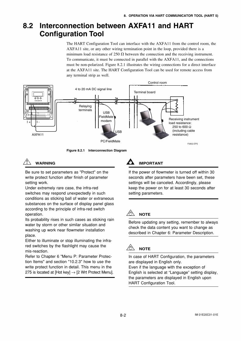
IM 01E20C01-01E8-2
8. OPERATION VIA HART COMMUNICATOR TOOL (HART 5)
8.2 Interconnection between AXFA11 and HARTConfiguration Tool
The HART Configuration Tool can interface with the AXFA11 from the control room, theAXFA11 site, or any other wiring termination point in the loop, provided there is aminimum load resistance of 250 between the connection and the receiving instrument.To communicate, it must be connected in parallel with the AXFA11, and the connectionsmust be non-polarized. Figure 8.2.1 illustrates the wiring connections for a direct interfaceat the AXFA11 site. The HART Configuration Tool can be used for remote access fromany terminal strip as well.
USBFieldMatemodem
USB
PC/FieldMate
AXFA11
4 to 20 mA DC signal line
Control room
Terminal board
Receiving instrumentload resistance:
250 to 600 Ω(including cable resistance)
Relayingterminals
I + I -
F0802.EPS
Figure 8.2.1 Interconnection Diagram
WARNING
Be sure to set parameters as "Protect" on thewrite protect function after finish of parametersetting work.Under extremely rare case, the infra-redswitches may respond unexpectedly in suchconditions as sticking ball of water or extraneoussubstances on the surface of display panel glassaccording to the principle of infra-red switchoperation.Its probability rises in such cases as sticking rainwater by storm or other similar situation andwashing up work near flowmeter installationplace.Either to illuminate or stop illuminating the infra-red switches by the flashlight may cause themis-reaction.Refer to Chapter 6 "Menu P: Parameter Protec-tion Items" and section "10.2.3" how to use thewrite protect function in detail. This menu in the275 is located at [Hot key] → [2 Wrt Protect Menu].
IMPORTANT
If the power of flowmeter is turned off within 30seconds after parameters have been set, thesesettings will be canceled. Accordingly, pleasekeep the power on for at least 30 seconds aftersetting parameters.
NOTE
Before updating any setting, remember to alwayscheck the data content you want to change asdescribed in Chapter 6: Parameter Description.
NOTE
In case of HART Configuration, the parametersare displayed in English only.Even if the language with the exception ofEnglish is selected at “Language” setting display,the parameters are displayed in English uponHART Configuration Tool.
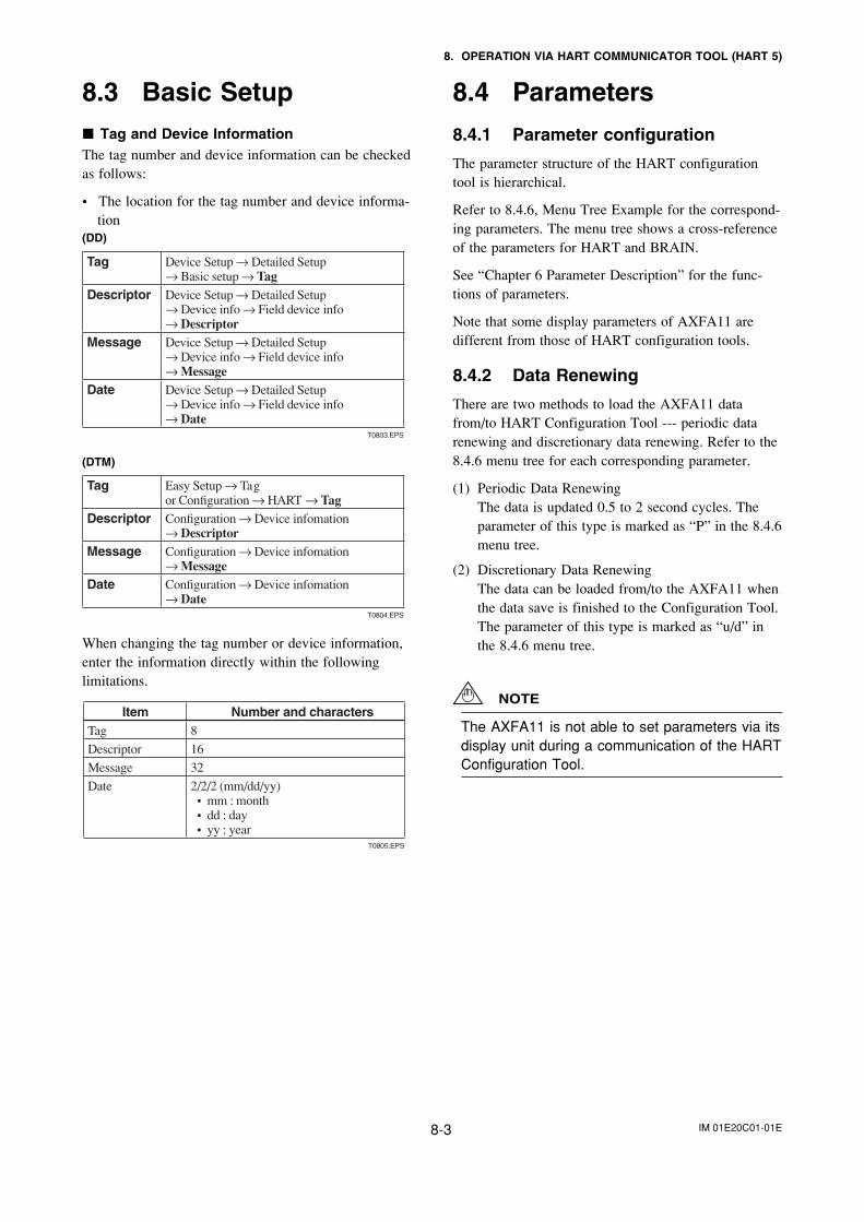
IM 01E20C01-01E8-3
8. OPERATION VIA HART COMMUNICATOR TOOL (HART 5)
8.3 Basic Setup Tag and Device InformationThe tag number and device information can be checkedas follows:
• The location for the tag number and device informa-tion
(DD)
Tag Device Setup → Detailed Setup → Basic setup → Tag
Descriptor Device Setup → Detailed Setup → Device info → Field device info → Descriptor
Message Device Setup → Detailed Setup → Device info → Field device info → Message
Date Device Setup → Detailed Setup → Device info → Field device info → Date
T0803.EPS
(DTM)
Tag Easy Setup → Tag or Confi guration → HART → Tag
Descriptor Confi guration → Device infomation → Descriptor
Message Confi guration → Device infomation → Message
Date Confi guration → Device infomation → Date
T0804.EPS
When changing the tag number or device information,enter the information directly within the followinglimitations.
Item Number and charactersTag 8
Descriptor 16
Message 32
Date 2/2/2 (mm/dd/yy)• mm : month• dd : day• yy : year
T0805.EPS
8.4 Parameters
8.4.1 Parameter configuration
The parameter structure of the HART configurationtool is hierarchical.
Refer to 8.4.6, Menu Tree Example for the correspond-ing parameters. The menu tree shows a cross-referenceof the parameters for HART and BRAIN.
See “Chapter 6 Parameter Description” for the func-tions of parameters.
Note that some display parameters of AXFA11 aredifferent from those of HART configuration tools.
8.4.2 Data Renewing
There are two methods to load the AXFA11 datafrom/to HART Configuration Tool --- periodic datarenewing and discretionary data renewing. Refer to the8.4.6 menu tree for each corresponding parameter.
(1) Periodic Data RenewingThe data is updated 0.5 to 2 second cycles. Theparameter of this type is marked as “P” in the 8.4.6menu tree.
(2) Discretionary Data RenewingThe data can be loaded from/to the AXFA11 whenthe data save is finished to the Configuration Tool.The parameter of this type is marked as “u/d” inthe 8.4.6 menu tree.
NOTE
The AXFA11 is not able to set parameters via itsdisplay unit during a communication of the HARTConfiguration Tool.
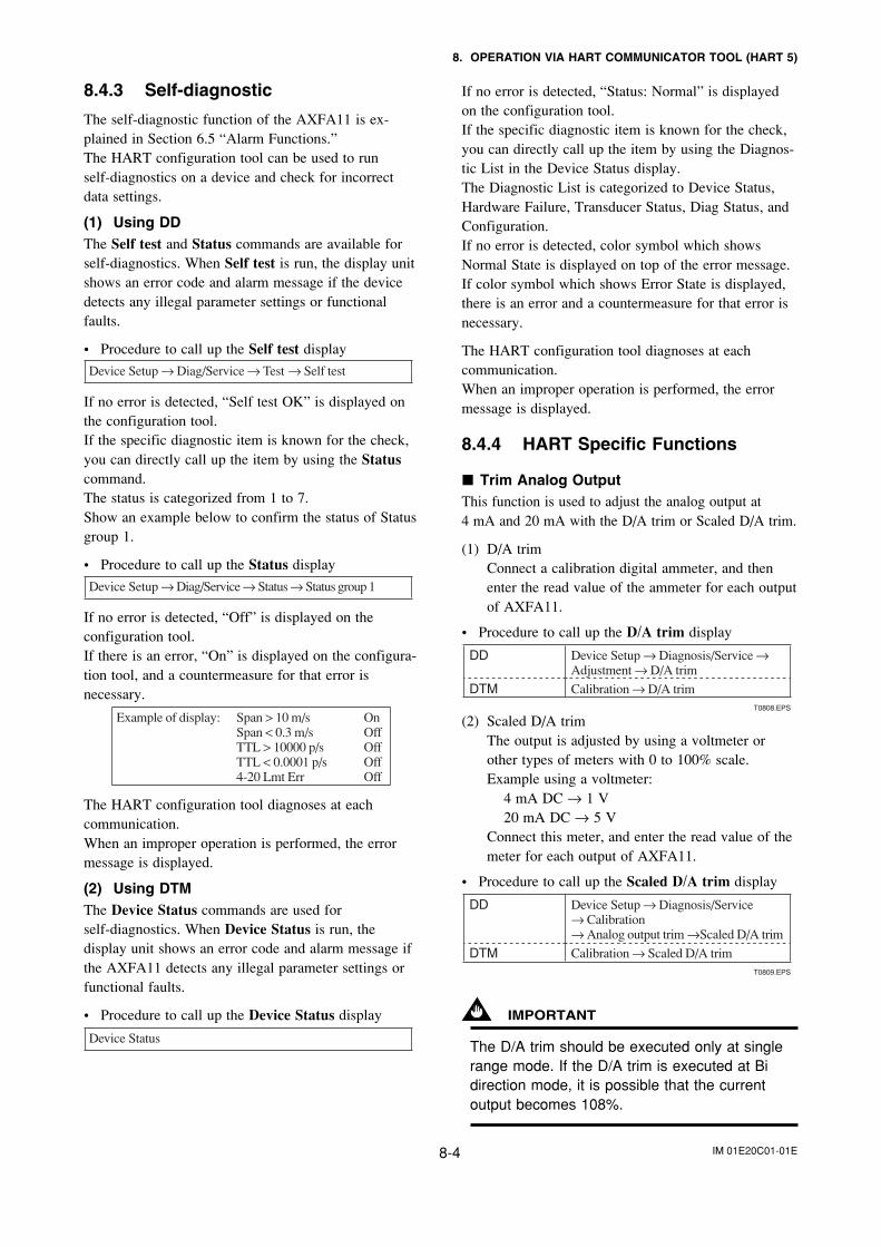
IM 01E20C01-01E8-4
8. OPERATION VIA HART COMMUNICATOR TOOL (HART 5)
8.4.3 Self-diagnostic
The self-diagnostic function of the AXFA11 is ex-plained in Section 6.5 “Alarm Functions.”The HART configuration tool can be used to runself-diagnostics on a device and check for incorrectdata settings.
(1) Using DDThe Self test and Status commands are available forself-diagnostics. When Self test is run, the display unitshows an error code and alarm message if the devicedetects any illegal parameter settings or functionalfaults.
• Procedure to call up the Self test display
Device Setup → Diag/Service → Test → Self test
If no error is detected, “Self test OK” is displayed onthe configuration tool.If the specific diagnostic item is known for the check,you can directly call up the item by using the Statuscommand.The status is categorized from 1 to 7.Show an example below to confirm the status of Statusgroup 1.
• Procedure to call up the Status display
Device Setup → Diag/Service → Status → Status group 1
If no error is detected, “Off” is displayed on theconfiguration tool.If there is an error, “On” is displayed on the configura-tion tool, and a countermeasure for that error isnecessary.
Example of display: Span > 10 m/s On Span < 0.3 m/s Off TTL > 10000 p/s Off TTL < 0.0001 p/s Off 4-20 Lmt Err Off
The HART configuration tool diagnoses at eachcommunication.When an improper operation is performed, the errormessage is displayed.
(2) Using DTMThe Device Status commands are used forself-diagnostics. When Device Status is run, thedisplay unit shows an error code and alarm message ifthe AXFA11 detects any illegal parameter settings orfunctional faults.
• Procedure to call up the Device Status display
Device Status
If no error is detected, “Status: Normal” is displayedon the configuration tool.If the specific diagnostic item is known for the check,you can directly call up the item by using the Diagnos-tic List in the Device Status display.The Diagnostic List is categorized to Device Status,Hardware Failure, Transducer Status, Diag Status, andConfiguration.If no error is detected, color symbol which showsNormal State is displayed on top of the error message.If color symbol which shows Error State is displayed,there is an error and a countermeasure for that error isnecessary.
The HART configuration tool diagnoses at eachcommunication.When an improper operation is performed, the errormessage is displayed.
8.4.4 HART Specific Functions
Trim Analog OutputThis function is used to adjust the analog output at4 mA and 20 mA with the D/A trim or Scaled D/A trim.
(1) D/A trimConnect a calibration digital ammeter, and thenenter the read value of the ammeter for each outputof AXFA11.
• Procedure to call up the D/A trim display
DD Device Setup → Diagnosis/Service → Adjustment → D/A trim
DTM Calibration → D/A trimT0808.EPS
(2) Scaled D/A trimThe output is adjusted by using a voltmeter orother types of meters with 0 to 100% scale.Example using a voltmeter:
4 mA DC → 1 V20 mA DC → 5 V
Connect this meter, and enter the read value of themeter for each output of AXFA11.
• Procedure to call up the Scaled D/A trim display
DD Device Setup → Diagnosis/Service → Calibration→ Analog output trim →Scaled D/A trim
DTM Calibration → Scaled D/A trimT0809.EPS
IMPORTANT
The D/A trim should be executed only at singlerange mode. If the D/A trim is executed at Bidirection mode, it is possible that the currentoutput becomes 108%.
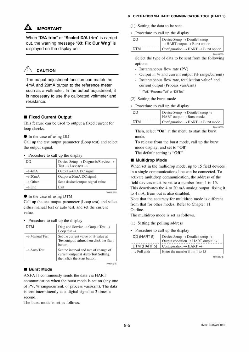
IM 01E20C01-01E8-5
8. OPERATION VIA HART COMMUNICATOR TOOL (HART 5)
IMPORTANT
When “D/A trim” or “Scaled D/A trim” is carriedout, the warning message “83: Fix Cur Wng” isdisplayed on the display unit.
CAUTION
The output adjustment function can match the4mA and 20mA output to the reference metersuch as a voltmeter. In the output adjustment, itis necessary to use the calibrated voltmeter andresistance.
Fixed Current OutputThis feature can be used to output a fixed current forloop checks.
In the case of using DDCall up the test output parameter (Loop test) and selectthe output signal.
• Procedure to call up the display
DD Device Setup → Diagnosis/Service → Test → Loop test →
→ 4mA Output a 4mA DC signal
→ 20mA Output a 20mA DC signal
→ Other Set a desired output signal value
→ End ExitT0806.EPS
In the case of using DTMCall up the test output parameter (Loop test) and selecteither manual test or auto test, and set the currentvalue.
• Procedure to call up the display
DTM Diag and Service → Output Test →Loop test →
→ Manual Test Set the current value or % value at Test output value, then click the Start button.
→ Auto Test Set the interval and rate of change of current output at Auto Test Setting, then click the Start button.
T0807.EPS
Burst ModeAXFA11 continuously sends the data via HARTcommunication when the burst mode is set on (any oneof PV, % range/current, or process vars/crnt). The datais sent intermittently as a digital signal at 3 times asecond.The burst mode is set as follows.
(1) Setting the data to be sent
• Procedure to call up the display
DD Device Setup → Detailed setup → HART output → Burst option
DTM Confi guration → HART → Burst optionT0810.EPS
Select the type of data to be sent from the followingoptions:- Instantaneous flow rate (PV)- Output in % and current output (% range/current)- Instantaneous flow rate, totalization value* and
current output (Process vars/crnt)
* “Totl,” “Reverse Totl” or “Dif Totl”
(2) Setting the burst mode
• Procedure to call up the display
DD Device Setup → Detailed setup → HART output → Burst mode
DTM Confi guration → HART → Burst mode T0811.EPS
Then, select “On” at the menu to start the burstmode.To release from the burst mode, call up the burstmode display, and set to “Off.”The default setting is “Off.”
Multidrop ModeWhen set in the multidrop mode, up to 15 field devicesin a single communications line can be connected. Toactivate multidrop communication, the address of thefield devices must be set to a number from 1 to 15.This deactivates the 4 to 20 mA analog output, fixing itto 4 mA. Burn out is also disabled.Note that the accuracy for multidrop mode is differentfrom that for other modes. Refer to Chapter 11:Outline.The multidrop mode is set as follows.
(1) Setting the polling address
• Procedure to call up the display
DD (HART 5) Device Setup → Detailed setup → Output condition → HART output →
DTM (HART 5) Confi guration → HART →→ Poll addr Enter the number from 1 to 15
T0812.EPS
IM 01E20C01-01E8-6
8. OPERATION VIA HART COMMUNICATOR TOOL (HART 5)
(2) Activating the multidrop modeAbout the procedure to call up the Polling display,please refer to the User’s Manual of each configu-ration tool.
NOTE
When the same polling address is assigned fortwo or more field devices in multidrop mode,communication with these field devices isdisabled.
(3) Communication when set in the multidrop mode
1. The HART configuration tool searches a fielddevice that is set in the multidrop mode whenthe HART configuration tool is turned on.When the HART configuration tool is connectedto the field device, the polling address and thetag will be displayed.
2. Select the field device, and then communicationwith it is possible. The communication speed isslow in this case.
3. To communicate with another field device, turnoff the power once and then turn it back on, orcall up “Online” menu, and select “Online.”The polling address and the tag will appear.Select the field device.
(4) Release of the multidrop modeCall up the “Poll addr” display, and set theaddress to “0.”
8.4.5 Other operations for the HARTconfiguration tool
Regarding other operations for the HART configura-tion tool, refer to the HART configuration tool opera-tions manual.
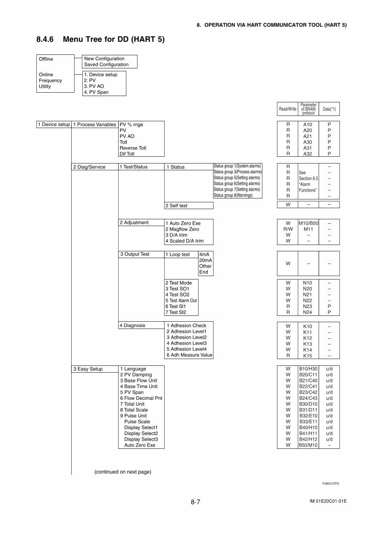
IM 01E20C01-01E8-7
8. OPERATION VIA HART COMMUNICATOR TOOL (HART 5)
8.4.6 Menu Tree for DD (HART 5)
1 Device setup 1 Process Variables PV % rngePVPV AOTotlReverse TotlDif Totl
2 Diag/Service 1 Test/Status 1 Status Status group 1(System alarms)Status group 3(Process alarms)Status group 5(Setting alarms)Status group 6(Setting alarms)Status group 7(Setting alarms)Status group 8(Warnings)
2 Self test
1 Auto Zero Exe2 Magflow Zero3 D/A trim4 Scaled D/A trim
2 Adjustment
3 Output Test 1 Loop test 4mA20mAOtherEnd
RRRRRR
– – – – – –
A10A20A21A30A31A32
PPPPPP
RRRRRR
M10/B50M11
– –
– – – –
WR/WWW
– –W
F0803.EPS
1 Adhesion Check2 Adhesion Level13 Adhesion Level24 Adhesion Level35 Adhesion Level46 Adh Measure Value
4 Diagnosis
3 Easy Setup 1 Language 2 PV Damping3 Base Flow Unit4 Base Time Unit5 PV Span6 Flow Decimal Pnt7 Total Unit8 Total Scale9 Pulse Unit Pulse Scale Display Select1 Display Select2 Display Select3 Auto Zero Exe
K10K11K12K13K14K15
––––––
N10N20N21N22N23N24
––––PP
WWWWWR
B10/H30B20/C11B21/C40B22/C41B23/C42B24/C43B30/D10B31/D11B32/E10B33/E11B40/H10B41/H11B42/H12B50/M10
u/du/du/du/du/du/du/du/du/du/du/du/du/d–
WWWWWWWWWWWWWW
SeeSection 6.5 “Alarm Functions”
W – –
Parameterof BRAIN protocol
Data(*1)
Read/Write
2 Test Mode3 Test SO14 Test SO25 Test Alarm Out6 Test SI17 Test SI2
WWWWRR
(continued on next page)
Offline
OnlineFrequencyUtility
New ConfigurationSaved Configuration
1. Device setup2. PV3. PV AO4. PV Span
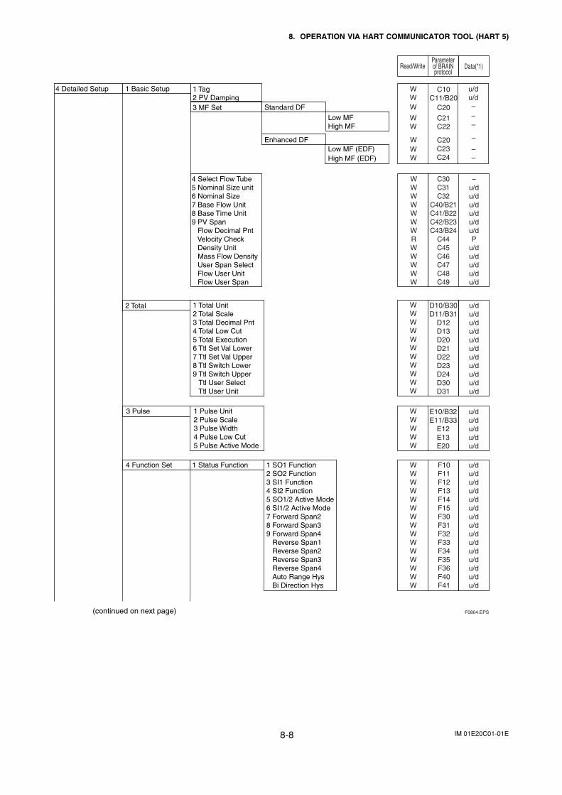
IM 01E20C01-01E8-8
8. OPERATION VIA HART COMMUNICATOR TOOL (HART 5)
Parameterof BRAIN protocol
Data(*1)
Read/Write
4 Detailed Setup 1 Basic Setup 1 Tag2 PV Damping3 MF Set Standard DF
Low MFHigh MF
Enhanced DFLow MF (EDF)High MF (EDF)
4 Select Flow Tube5 Nominal Size unit6 Nominal Size7 Base Flow Unit8 Base Time Unit9 PV Span Flow Decimal Pnt Velocity Check Density Unit Mass Flow Density User Span Select Flow User Unit Flow User Span
C10C11/B20
C20
C21C22
WWW
C30C31C32
C40/B21C41/B22C42/B23C43/B24
C44C45C46C47C48C49
–u/du/du/du/du/du/dP
u/du/du/du/du/d
WWWWWWWRWWWWW
WW
WW
W
u/du/d–
––
––
–
C23C24
C20
2 Total 1 Total Unit2 Total Scale3 Total Decimal Pnt4 Total Low Cut5 Total Execution6 Ttl Set Val Lower7 Ttl Set Val Upper8 Ttl Switch Lower9 Ttl Switch Upper Ttl User Select Ttl User Unit
3 Pulse 1 Pulse Unit2 Pulse Scale3 Pulse Width4 Pulse Low Cut5 Pulse Active Mode
4 Function Set 1 Status Function 1 SO1 Function2 SO2 Function3 SI1 Function4 SI2 Function5 SO1/2 Active Mode6 SI1/2 Active Mode7 Forward Span28 Forward Span39 Forward Span4 Reverse Span1 Reverse Span2 Reverse Span3 Reverse Span4 Auto Range Hys Bi Direction Hys
D10/B30D11/B31
D12D13D20D21D22D23D24D30D31
u/du/du/du/du/du/du/du/du/du/du/d
WWWWWWWWWWW
E10/B32E11/B33
E12E13E20
u/du/du/du/du/d
WWWWW
F10F11F12F13F14F15F30F31F32F33F34F35F36F40F41
u/du/du/du/du/du/du/du/du/du/du/du/du/du/du/d
WWWWWWWWWWWWWWW
F0804.EPS(continued on next page)
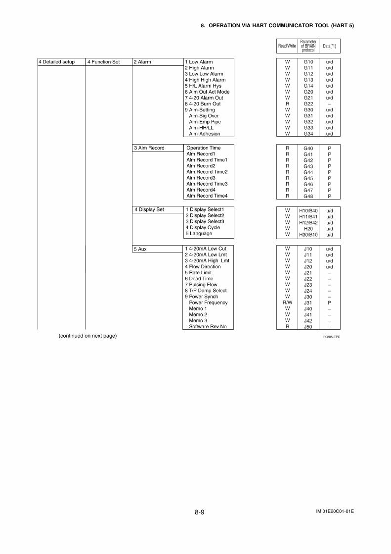
IM 01E20C01-01E8-9
8. OPERATION VIA HART COMMUNICATOR TOOL (HART 5)
Parameterof BRAIN protocol
Data(*1)
Read/Write
5 Aux 1 4-20mA Low Cut2 4-20mA Low Lmt3 4-20mA High Lmt4 Flow Direction5 Rate Limit6 Dead Time7 Pulsing Flow8 T/P Damp Select9 Power Synch Power Frequency Memo 1 Memo 2 Memo 3 Software Rev No
J10J11J12J20J21J22J23J24J30J31J40J41J42J50
u/du/du/du/d–––––P––––
WWWWWWWWW
R/WWWWR
F0805.EPS(continued on next page)
2 Alarm 1 Low Alarm2 High Alarm3 Low Low Alarm4 High High Alarm5 H/L Alarm Hys6 Alm Out Act Mode7 4-20 Alarm Out8 4-20 Burn Out9 Alm-Setting Alm-Sig Over Alm-Emp Pipe Alm-HH/LL Alm-Adhesion
3 Alm Record Operation TimeAlm Record1Alm Record Time1Alm Record2Alm Record Time2Alm Record3Alm Record Time3Alm Record4Alm Record Time4
4 Display Set 1 Display Select12 Display Select23 Display Select34 Display Cycle5 Language
4 Detailed setup 4 Function Set G10G11G12G13G14G20G21G22G30G31G32G33G34
u/du/du/du/du/du/du/d–
u/du/du/du/du/d
WWWWWWWRWWWWW
H10/B40H11/B41H12/B42
H20H30/B10
u/du/du/du/du/d
WWWWW
G40G41G42G43G44G45G46G47G48
PPPPPPPPP
RRRRRRRRR
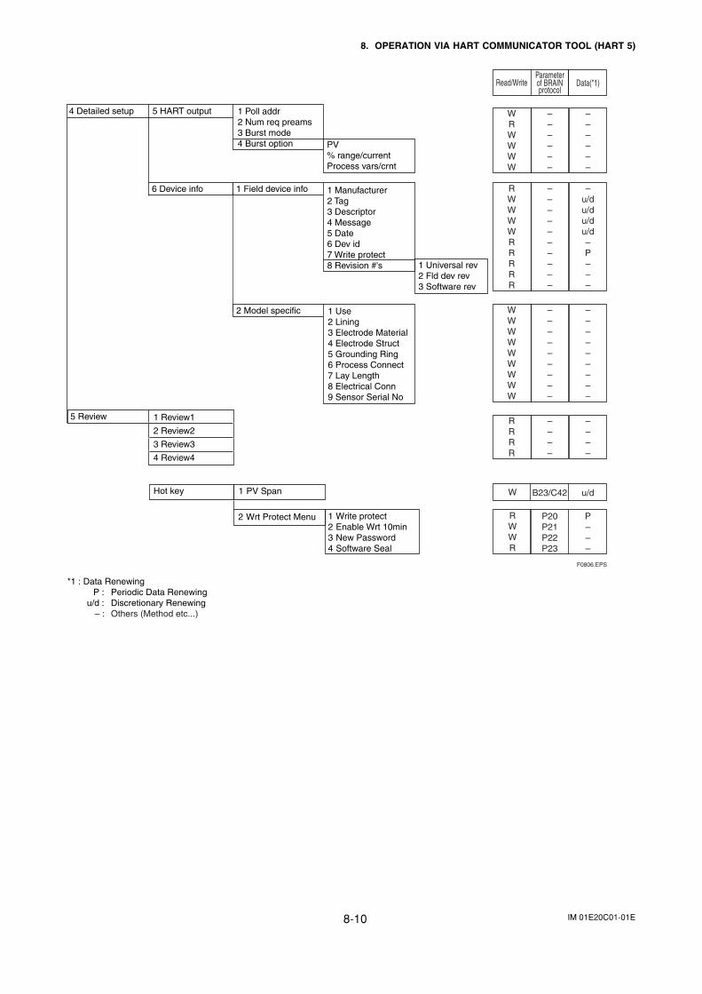
IM 01E20C01-01E8-10
8. OPERATION VIA HART COMMUNICATOR TOOL (HART 5)
Parameterof BRAIN protocol
Data(*1)
Read/Write
WRWWWW
––––––
––––––
RWWWWRRRRR
––––––––––
–u/du/du/du/d–P–––
WWWWWWWWW
–––––––––
–––––––––
RRRR
––––
––––
P20P21P22P23
P–––
RWWR
B23/C42 u/dW
4 Detailed setup 5 HART output 1 Poll addr2 Num req preams3 Burst mode4 Burst option
6 Device info 1 Field device info 1 Manufacturer2 Tag3 Descriptor4 Message5 Date6 Dev id7 Write protect8 Revision #'s 1 Universal rev
2 Fld dev rev3 Software rev
2 Model specific 1 Use2 Lining3 Electrode Material4 Electrode Struct5 Grounding Ring6 Process Connect7 Lay Length8 Electrical Conn9 Sensor Serial No
5 Review 1 Review1
2 Review2
3 Review3
4 Review4
F0806.EPS
PV% range/currentProcess vars/crnt
Hot key 1 PV Span
2 Wrt Protect Menu 1 Write protect 2 Enable Wrt 10min 3 New Password 4 Software Seal
*1 : Data RenewingP : Periodic Data Renewing
u/d : Discretionary Renewing– : Others (Method etc...)
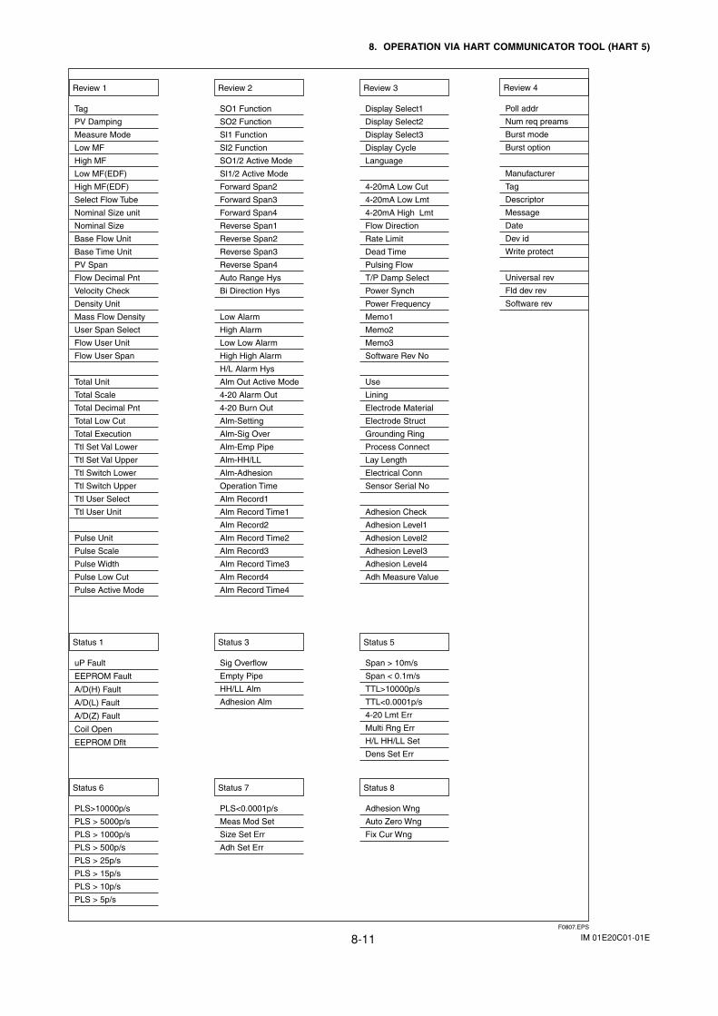
IM 01E20C01-01E8-11
8. OPERATION VIA HART COMMUNICATOR TOOL (HART 5)
Review 1
Tag
PV Damping
Measure Mode
Low MF
High MF
Low MF(EDF)
High MF(EDF)
Select Flow Tube
Nominal Size unit
Nominal Size
Base Flow Unit
Base Time Unit
PV Span
Flow Decimal Pnt
Velocity Check
Density Unit
Mass Flow Density
User Span Select
Flow User Unit
Flow User Span
Total Unit
Total Scale
Total Decimal Pnt
Total Low Cut
Total Execution
Ttl Set Val Lower
Ttl Set Val Upper
Ttl Switch Lower
Ttl Switch Upper
Ttl User Select
Ttl User Unit
Pulse Unit
Pulse Scale
Pulse Width
Pulse Low Cut
Pulse Active Mode
Review 2
SO1 Function
SO2 Function
SI1 Function
SI2 Function
SO1/2 Active Mode
SI1/2 Active Mode
Forward Span2
Forward Span3
Forward Span4
Reverse Span1
Reverse Span2
Reverse Span3
Reverse Span4
Auto Range Hys
Bi Direction Hys
Low Alarm
High Alarm
Low Low Alarm
High High Alarm
H/L Alarm Hys
Alm Out Active Mode
4-20 Alarm Out
4-20 Burn Out
Alm-Setting
Alm-Sig Over
Alm-Emp Pipe
Alm-HH/LL
Alm-Adhesion
Operation Time
Alm Record1
Alm Record Time1
Alm Record2
Alm Record Time2
Alm Record3
Alm Record Time3
Alm Record4
Alm Record Time4
Review 3
Display Select1
Display Select2
Display Select3
Display Cycle
Language
4-20mA Low Cut
4-20mA Low Lmt
4-20mA High Lmt
Flow Direction
Rate Limit
Dead Time
Pulsing Flow
T/P Damp Select
Power Synch
Power Frequency
Memo1
Memo2
Memo3
Software Rev No
Use
Lining
Electrode Material
Electrode Struct
Grounding Ring
Process Connect
Lay Length
Electrical Conn
Sensor Serial No
Adhesion Check
Adhesion Level1
Adhesion Level2
Adhesion Level3
Adhesion Level4
Adh Measure Value
Review 4
Poll addr
Num req preams
Burst mode
Burst option
Manufacturer
Tag
Descriptor
Message
Date
Dev id
Write protect
Universal rev
Fld dev rev
Software rev
Status 1
uP Fault
EEPROM Fault
A/D(H) Fault
A/D(L) Fault
A/D(Z) Fault
Coil Open
EEPROM Dflt
Status 3
Sig Overflow
Empty Pipe
HH/LL Alm
Adhesion Alm
Status 5
Span > 10m/s
Span < 0.1m/s
TTL>10000p/s
TTL<0.0001p/s
4-20 Lmt Err
Multi Rng Err
H/L HH/LL Set
Dens Set Err
F0807.EPS
Status 6
PLS>10000p/s
PLS > 5000p/s
PLS > 1000p/s
PLS > 500p/s
PLS > 25p/s
PLS > 15p/s
PLS > 10p/s
PLS > 5p/s
Status 7
PLS<0.0001p/s
Meas Mod Set
Size Set Err
Adh Set Err
Status 8
Adhesion Wng
Auto Zero Wng
Fix Cur Wng
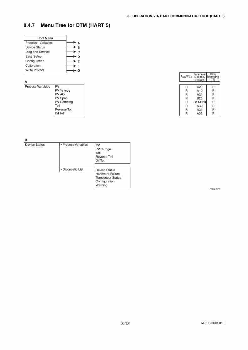
IM 01E20C01-01E8-12
8. OPERATION VIA HART COMMUNICATOR TOOL (HART 5)
8.4.7 Menu Tree for DTM (HART 5)
Process Variables PVPV % rngePV AOPV SpanPV DampingTotlReverse TotlDif Totl
A20A10A21B23
C11/B20A30A31A32
RRRRRRRR
Read/Write
PPPPPPPP
DataRenewing
(*1)
Parameterof BRAINprotocol
Root Menu
Process Variables
Device Status
Diag and Service
Easy Setup
Configuration
Calibration
Write Protect
ABCDEFG
A
B
PVPV % rngeTotlReverse TotlDif Totl
Device Status • Process Variables
• Diagnostic List Device StatusHardware FailureTransducer StatusConfigurationWarning
F0808.EPS
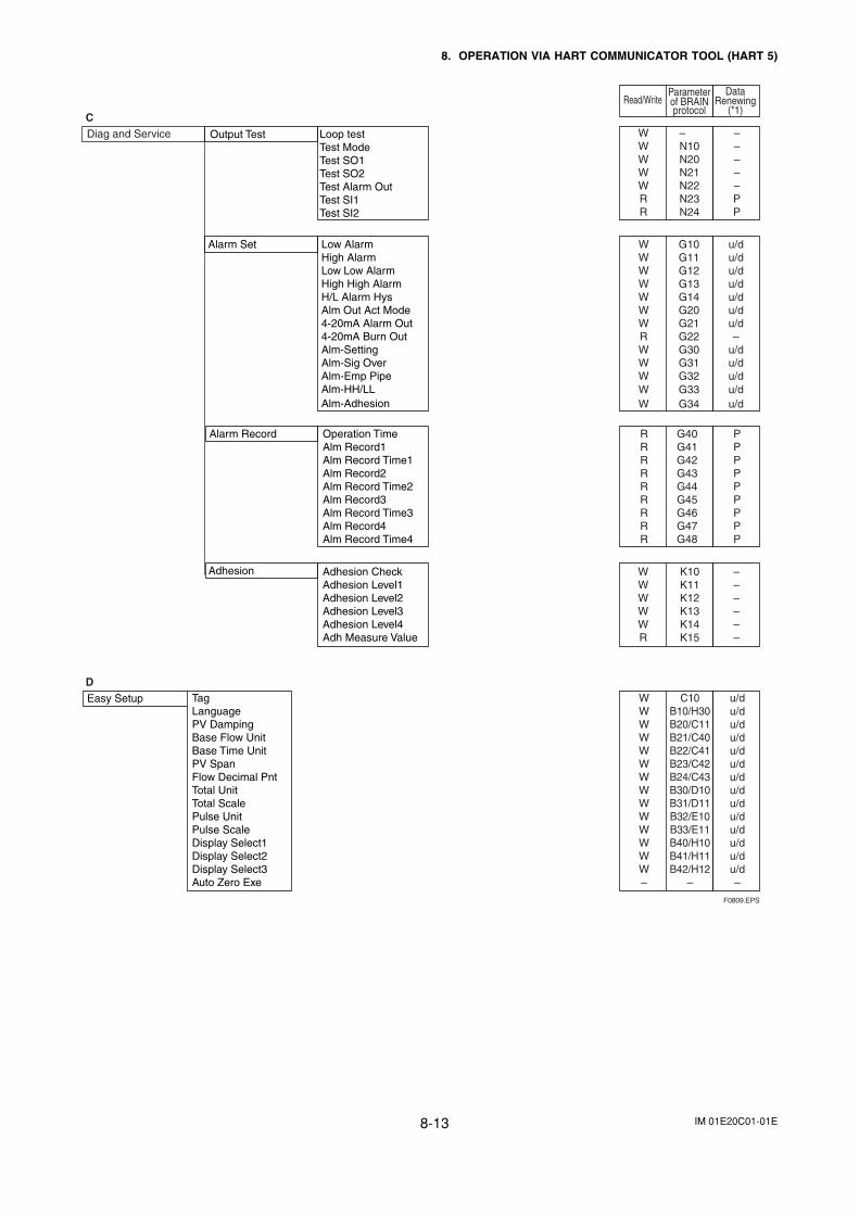
IM 01E20C01-01E8-13
8. OPERATION VIA HART COMMUNICATOR TOOL (HART 5)
Read/Write
DataRenewing
(*1)
Parameterof BRAINprotocol
C
D
Diag and Service Output Test Loop testTest ModeTest SO1Test SO2Test Alarm OutTest SI1Test SI2
–N10N20N21N22N23N24
WWWWWRR
–––––PP
Alarm Set Low AlarmHigh AlarmLow Low AlarmHigh High AlarmH/L Alarm HysAlm Out Act Mode4-20mA Alarm Out4-20mA Burn OutAlm-SettingAlm-Sig OverAlm-Emp PipeAlm-HH/LLAlm-Adhesion
G10G11G12G13G14G20G21G22G30G31G32
WWWWWWWRWWW
u/du/du/du/du/du/du/d–
u/du/du/d
G33W u/dG34W u/d
Alarm Record Operation TimeAlm Record1Alm Record Time1Alm Record2Alm Record Time2Alm Record3Alm Record Time3Alm Record4Alm Record Time4
G40G41G42G43G44G45G46G47G48
RRRRRRRRR
PPPPPPPPP
Adhesion Adhesion CheckAdhesion Level1Adhesion Level2Adhesion Level3Adhesion Level4Adh Measure Value
K10K11K12K13K14K15
WWWWWR
––––––
Easy Setup TagLanguage PV DampingBase Flow UnitBase Time UnitPV SpanFlow Decimal PntTotal UnitTotal ScalePulse UnitPulse ScaleDisplay Select1Display Select2Display Select3Auto Zero Exe
C10B10/H30B20/C11B21/C40B22/C41B23/C42B24/C43B30/D10B31/D11B32/E10B33/E11B40/H10B41/H11B42/H12
–
WWWWWWWWWWWWWW–
u/du/du/du/du/du/du/du/du/du/du/du/du/du/d–
F0809.EPS
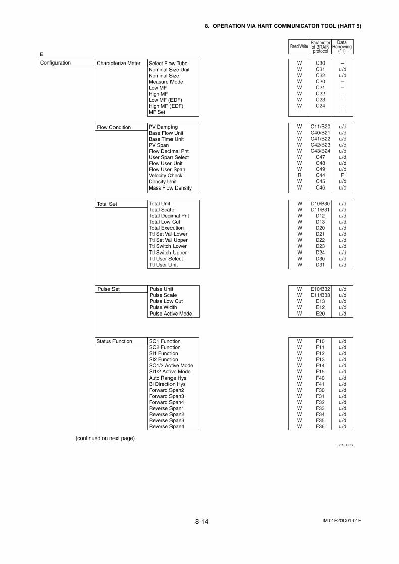
IM 01E20C01-01E8-14
8. OPERATION VIA HART COMMUNICATOR TOOL (HART 5)
Read/Write
DataRenewing
(*1)
Parameterof BRAINprotocol
E
Pulse Set
Total Set
Select Flow TubeNominal Size UnitNominal SizeMeasure ModeLow MFHigh MFLow MF (EDF)High MF (EDF)MF Set
PV DampingBase Flow UnitBase Time UnitPV SpanFlow Decimal PntUser Span SelectFlow User UnitFlow User SpanVelocity CheckDensity UnitMass Flow Density
Pulse UnitPulse ScalePulse Low CutPulse WidthPulse Active Mode
Total UnitTotal ScaleTotal Decimal PntTotal Low CutTotal ExecutionTtl Set Val LowerTtl Set Val UpperTtl Switch LowerTtl Switch UpperTtl User SelectTtl User Unit
Characterize Meter
Flow Condition
C30C31C32C20C21C22C23C24
–
WWWWWWWW–
–u/du/d––––––
C11/B20C40/B21C41/B22C42/B23C43/B24
C47C48C49C44C45C46
WWWWWWWWRWW
D10/B30D11/B31
D12D13
WWWWWWWWWWW
u/du/du/du/du/du/du/du/du/du/du/d
E10/B32E11/B33
E13E12E20
WWWWW
u/du/du/du/du/d
Status Function SO1 FunctionSO2 FunctionSI1 FunctionSI2 FunctionSO1/2 Active ModeSI1/2 Active ModeAuto Range HysBi Direction HysForward Span2Forward Span3Forward Span4Reverse Span1Reverse Span2Reverse Span3Reverse Span4
F10F11F12F13F14F15F40F41F30F31F32F33F34F35F36
WWWWWWWWWWWWWWW
u/du/du/du/du/du/du/du/du/du/du/du/du/du/du/d
(continued on next page)
Configuration
F0810.EPS
u/du/du/du/du/du/du/du/dP
u/du/d
D20D21D22D23D24D30D31
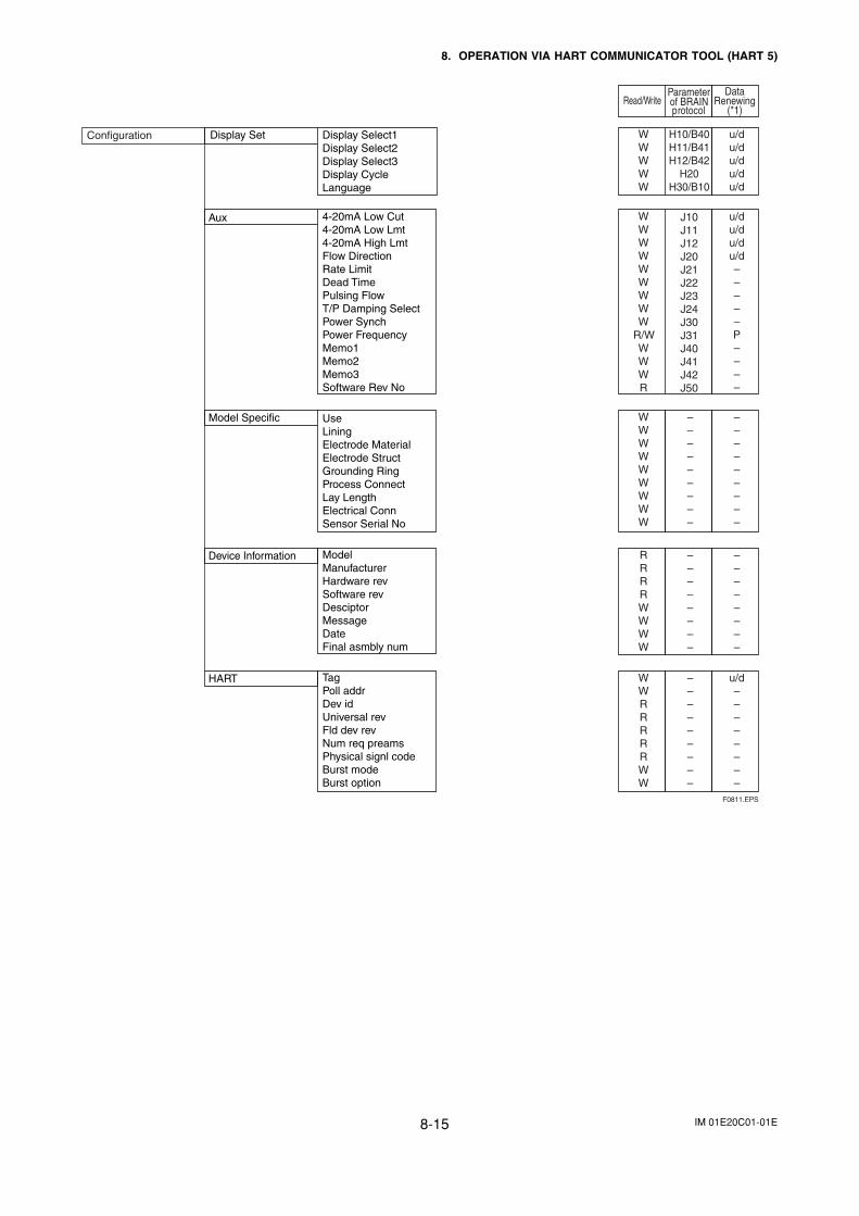
IM 01E20C01-01E8-15
8. OPERATION VIA HART COMMUNICATOR TOOL (HART 5)
Read/Write
DataRenewing
(*1)
Parameterof BRAINprotocol
Configuration
Aux 4-20mA Low Cut4-20mA Low Lmt4-20mA High LmtFlow DirectionRate LimitDead TimePulsing FlowT/P Damping SelectPower SynchPower FrequencyMemo1Memo2Memo3Software Rev No
Display Set Display Select1Display Select2Display Select3Display CycleLanguage
Model Specific UseLiningElectrode MaterialElectrode StructGrounding RingProcess ConnectLay LengthElectrical ConnSensor Serial No
Device Information ModelManufacturerHardware revSoftware revDesciptorMessageDateFinal asmbly num
HART TagPoll addrDev idUniversal revFld dev revNum req preamsPhysical signl codeBurst modeBurst option
H10/B40H11/B41H12/B42
H20H30/B10
WWWWW
u/du/du/du/du/d
J10J11J12J20J21J22J23J24J30J31J40J41J42J50
WWWWWWWWW
R/WWWWR
u/du/du/du/d–––––P––––
–––––––––
–––––––––
WWWWWWWWW
––––––––
––––––––
RRRRWWWW
u/d––––––––
–––––––––
WWRRRRRWW
F0811.EPS
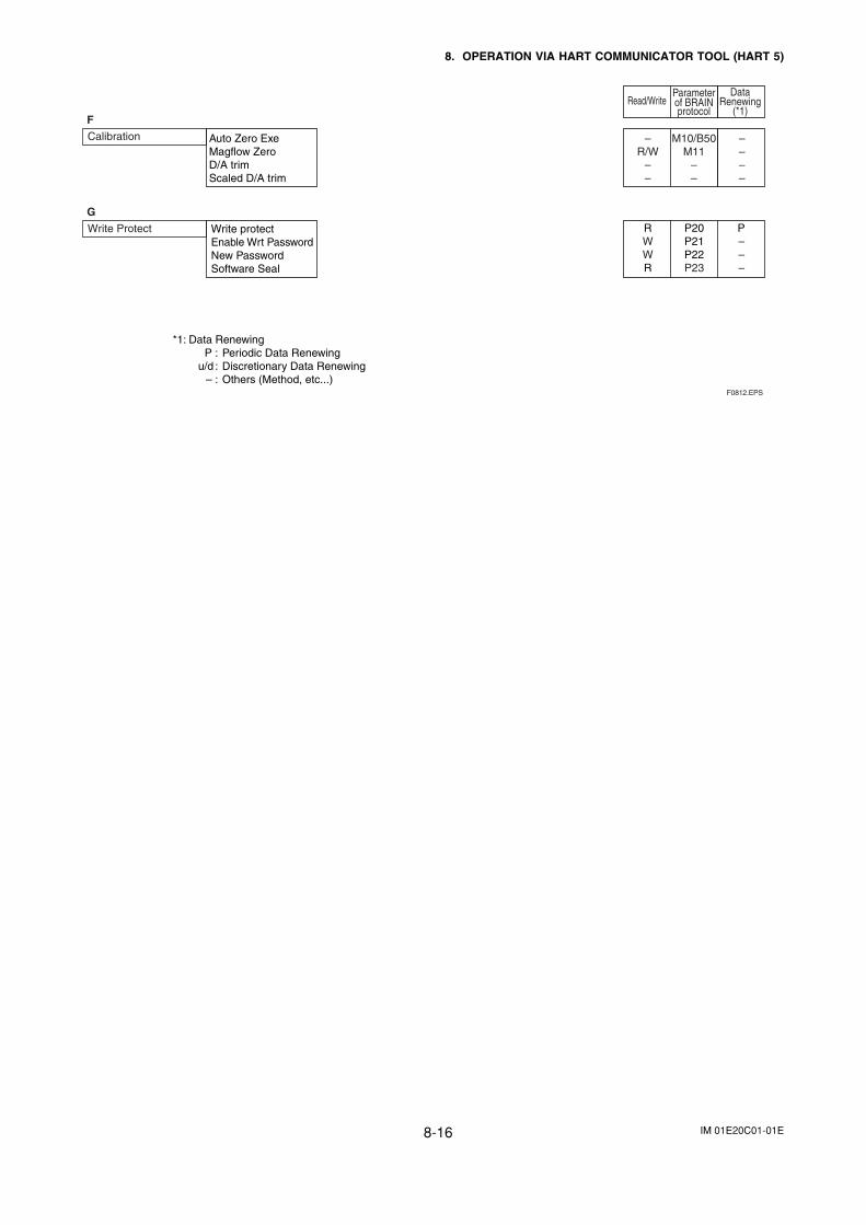
IM 01E20C01-01E8-16
8. OPERATION VIA HART COMMUNICATOR TOOL (HART 5)
Read/Write
DataRenewing
(*1)
Parameterof BRAINprotocol
Calibration
F
Write Protect
G
Auto Zero ExeMagflow ZeroD/A trimScaled D/A trim
M10/B50M11
––
–R/W
––
––––
Write protectEnable Wrt PasswordNew PasswordSoftware Seal
P–––
P20P21P22P23
RWWR
*1: Data RenewingP : Periodic Data Renewing
u/d : Discretionary Data Renewing– : Others (Method, etc...)
F0812.EPS
IM 01E20C01-01E9-1
9. ACTUAL OPERATION
9. ACTUAL OPERATION
After you have installed the flowtube into the processpiping, wired the input/output terminals, set up therequired parameters, and performed a pre-operationzero adjustment, the magnetic flowmeter should outputan accurate flow signal from its terminals as soon asflow of the fluid to be measured begins. This sectiondescribes zero adjustment and the correspondingprocedures.
9.1 Pre-operation ZeroAdjustment
Zero adjustment is carried out to ensure that the outputfor zero flow is 0% (i.e., 4 mA). Although adjustmentto zero is performed at the manufacturing plant prior toshipment, this procedure must be carried out onceagain following the installation of piping in order tomatch the magnetic flowmeter to its operating condi-tions.
This section describes the zero adjustment procedureusing display unit switches from the converter andusing the external status input; accordingly, one ofthese methods should be selected and implemented.
IMPORTANT
• Zero adjustment should be carried out beforeactual operation. Note that setting and updatefunctions cannot be carried out during thisprocedure (i.e., for approximately 30 seconds).
• Zero adjustment should only be carried outwhen the flowtube has been filled withmesurement fluid and the fluid velocity iscompletely zero by closing the valve.
• Each time that the fluid being measured ischanged, it will be necessary for zero adjust-ment to be carried out for the new fluid.
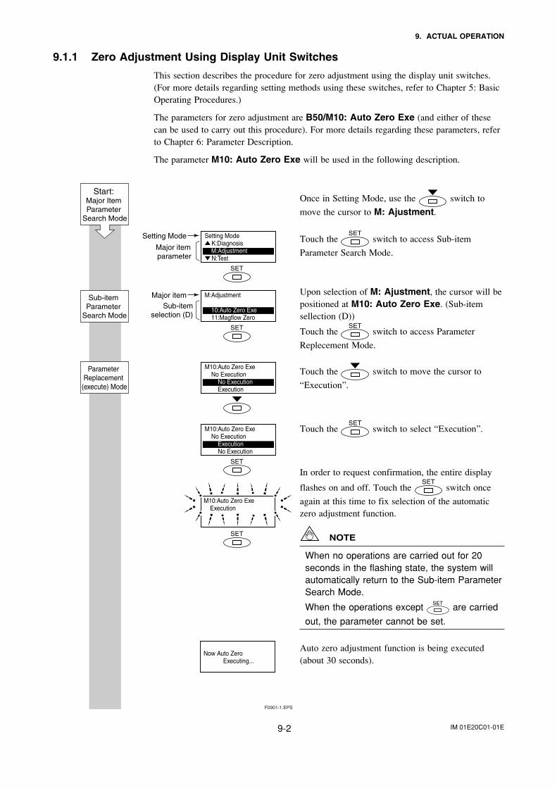
IM 01E20C01-01E9-2
9. ACTUAL OPERATION
9.1.1 Zero Adjustment Using Display Unit Switches
This section describes the procedure for zero adjustment using the display unit switches.(For more details regarding setting methods using these switches, refer to Chapter 5: BasicOperating Procedures.)
The parameters for zero adjustment are B50/M10: Auto Zero Exe (and either of thesecan be used to carry out this procedure). For more details regarding these parameters, referto Chapter 6: Parameter Description.
The parameter M10: Auto Zero Exe will be used in the following description.
Once in Setting Mode, use the switch to
move the cursor to M: Ajustment.
Touch the switch to access Sub-item
Parameter Search Mode.
Upon selection of M: Ajustment, the cursor will bepositioned at M10: Auto Zero Exe. (Sub-itemsellection (D))
Touch the switch to access Parameter
Replecement Mode.
Touch the switch to move the cursor to
“Execution”.
Touch the switch to select “Execution”.
In order to request confirmation, the entire display
flashes on and off. Touch the switch once
again at this time to fix selection of the automaticzero adjustment function.
NOTE
When no operations are carried out for 20seconds in the flashing state, the system willautomatically return to the Sub-item ParameterSearch Mode.
When the operations except are carried
out, the parameter cannot be set.
Auto zero adjustment function is being executed(about 30 seconds).
F0901-1.EPS
Setting Mode
Major item parameter
Setting ModeK:Diagnosis
M:AdjustmentN:Test
M10:Auto Zero Exe No Execution No Execution Execution
M10:Auto Zero Exe No Execution Execution No Execution
Major itemSub-item
selection (D)
M:Adjustment
10:Auto Zero Exe 11:Magflow Zero
M10:Auto Zero Exe Execution
Sub-item Parameter
Search Mode
Parameter Replacement
(execute) Mode
Start: Major Item Parameter
Search Mode
Now Auto Zero Executing...
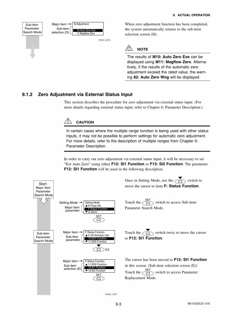
IM 01E20C01-01E9-3
9. ACTUAL OPERATION
When zero adjustment function has been completed,the system automatically returns to the sub-itemselection screen (D).
NOTE
The results of M10: Auto Zero Exe can bedisplayed using M11: Magflow Zero. Alterna-tively, if the results of the automatic zeroadjustment exceed the rated value, the warn-ing 82: Auto Zero Wng will be displayed.
9.1.2 Zero Adjustment via External Status Input
This section describes the procedure for zero adjustment via external status input. (Formore details regarding external status input, refer to Chapter 6: Parameter Description.)
CAUTION
In certain cases where the multiple range function is being used with other statusinputs, it may not be possible to perform settings for automatic zero adjustment.For more details, refer to the description of multiple ranges from Chapter 6:Parameter Description.
In order to carry out zero adjustment via external status input, it will be necessary to set“Ext Auto Zero” using either F12: SI1 Function or F13: SI2 Function. The parameterF12: SI1 Function will be used in the following description.
Once in Setting Mode, use the switch to
move the cursor to item F: Status Function.
Touch the switch to access Sub-item
Parameter Search Mode.
Touch the switch twice to move the cursor
to F12: SI1 Function.
The cursor has been moved to F12: SI1 Function
in this screen. (Sub-item selection screen (E))
Touch the switch to access Parameter
Replacement Mode.
F0902-1.EPS
Setting Mode
Major item parameter
Setting ModeE:Pulse SetF:Status FunctionG:Alarm
Major itemSub-itemparameter
Major itemSub-itemselection (E)
F:Status Function41:Bi Direction Hys10:SO1 Function11:SO2 Function
F:Status Function11:SO2 Function12:SI1 Function13:SI2 Function
X2
Sub-item Parameter
Search Mode
Start: Major Item Parameter
Search Mode
F0901-2.EPS
Major itemSub-item
selection (D)
M:Adjustment
10:Auto Zero Exe 11:Magflow Zero
Sub-item Parameter
Search Mode
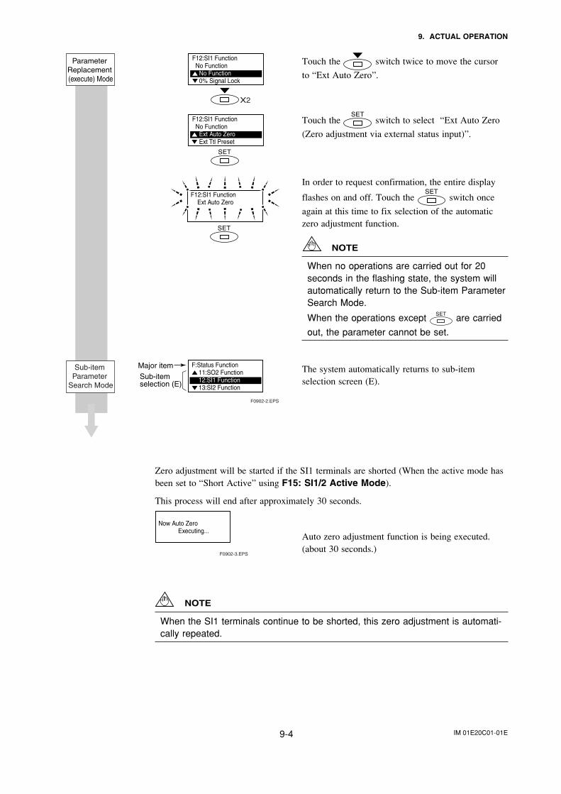
IM 01E20C01-01E9-4
9. ACTUAL OPERATION
Touch the switch twice to move the cursor
to “Ext Auto Zero”.
Touch the switch to select “Ext Auto Zero
(Zero adjustment via external status input)”.
In order to request confirmation, the entire display
flashes on and off. Touch the switch once
again at this time to fix selection of the automaticzero adjustment function.
NOTE
When no operations are carried out for 20seconds in the flashing state, the system willautomatically return to the Sub-item ParameterSearch Mode.
When the operations except are carried
out, the parameter cannot be set.
The system automatically returns to sub-itemselection screen (E).
Zero adjustment will be started if the SI1 terminals are shorted (When the active mode hasbeen set to “Short Active” using F15: SI1/2 Active Mode).
This process will end after approximately 30 seconds.
Auto zero adjustment function is being executed.(about 30 seconds.)
NOTE
When the SI1 terminals continue to be shorted, this zero adjustment is automati-cally repeated.
F0902-2.EPS
F:Status Function11:SO2 Function12:SI1 Function13:SI2 Function
F12:SI1 Function Ext Auto Zero
Sub-item Parameter
Search Mode
F12:SI1 Function No Function
Ext Auto ZeroExt Ttl Preset
Major itemSub-itemselection (E)
F12:SI1 Function No Function
No Function0% Signal Lock
X2
Parameter Replacement (execute) Mode
F0902-3.EPS
Now Auto Zero Executing...
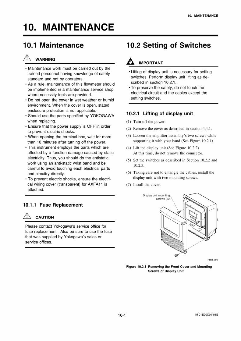
IM 01E20C01-01E10-1
10. MAINTENANCE
10. MAINTENANCE
10.2 Setting of Switches
IMPORTANT
• Lifting of display unit is necessary for settingswitches. Perform display unit lifting as de-scribed in section 10.2.1.
• To preserve the safety, do not touch theelectrical circuit and the cables except thesetting switches.
10.2.1 Lifting of display unit
(1) Turn off the power.
(2) Remove the cover as described in section 4.4.1.
(3) Loosen the amplifier assembly’s two screws whilesupporting it with your hand (See Figure 10.2.1).
(4) Lift the display unit (See Figure 10.2.2).At this time, do not remove the connector.
(5) Set the switches as described in Section 10.2.2 and10.2.3.
(6) Taking care not to entangle the cables, install thedisplay unit with two mounting screws.
(7) Install the cover.
F1008.EPS
Display unit mounting screws (x2)
Figure 10.2.1 Removing the Front Cover and MountingScrews of Display Unit
10.1 Maintenance
WARNING
• Maintenance work must be carried out by thetrained personnel having knowledge of safetystandard and not by operators.
• As a rule, maintenance of this flowmeter shouldbe implemented in a maintenance service shopwhere necessity tools are provided.
• Do not open the cover in wet weather or humidenvironment. When the cover is open, statedenclosure protection is not applicable.
• Should use the parts specified by YOKOGAWAwhen replacing.
• Ensure that the power supply is OFF in orderto prevent electric shocks.
• When opening the terminal box, wait for morethan 10 minutes after turning off the power.
• This instrument employs the parts which areaffected by a function damage caused by staticelectricity. Thus, you should do the antistaticwork using an anti-static wrist band and becareful to avoid touching each electrical partsand circuitry directly.
• To prevent electric shocks, ensure the electri-cal wiring cover (transparent) for AXFA11 isattached.
10.1.1 Fuse Replacement
CAUTION
Please contact Yokogawa's service office forfuse replacement. Also be sure to use the fusethat was supplied by Yokogawa’s sales orservice offices.
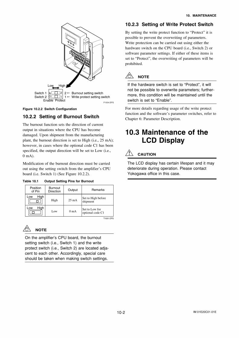
IM 01E20C01-01E10-2
10. MAINTENANCE
F1004.EPSEnable Protect
Switch 1 2 Burnout setting switchSwitch 2 1 Write protect setting switch
Low High
Figure 10.2.2 Switch Configuration
10.2.2 Setting of Burnout Switch
The burnout function sets the direction of currentoutput in situations where the CPU has becomedamaged. Upon shipment from the manufacturingplant, the burnout direction is set to High (i.e., 25 mA);however, in cases where the optional code C1 has beenspecified, the output direction will be set to Low (i.e.,0 mA).
Modification of the burnout direction must be carriedout using the setting switch from the amplifier’s CPUboard (i.e. Switch 1) (See Figure 10.2.2).
Table 10.1 Output Setting Pins for Burnout
T1001.EPS
Positionof Pin
BurnoutDirection Output Remarks
Low High
Low High
Low
High
0 mA
25 mA
Set to Low for optional code C1
Set to High before shipment
NOTE
On the amplifier’s CPU board, the burnoutsetting switch (i.e., Switch 1) and the writeprotect switch (i.e., Switch 2) are located adja-cent to each other. Accordingly, special careshould be taken when making switch settings.
10.2.3 Setting of Write Protect Switch
By setting the write protect function to “Protect” it ispossible to prevent the overwriting of parameters.Write protection can be carried out using either thehardware switch on the CPU board (i.e., Switch 2) orsoftware parameter settings. If either of these items isset to “Protect”, the overwriting of parameters will beprohibited.
NOTE
If the hardware switch is set to “Protect”, it willnot be possible to overwrite parameters; further-more, this condition will be maintained until theswitch is set to “Enable”.
For more details regarding usage of the write protectfunction and the software’s parameter switches, refer toChapter 6: Parameter Description.
10.3 Maintenance of theLCD Display
CAUTION
The LCD display has certain lifespan and it maydeteriorate during operation. Please contactYokogawa office in this case.
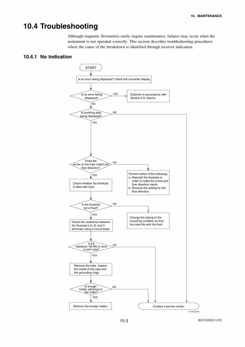
IM 01E20C01-01E10-3
10. MAINTENANCE
10.4 TroubleshootingAlthough magnetic flowmeters rarely require maintenance, failures may occur when theinstrument is not operated correctly. This section describes troubleshooting procedureswhere the cause of the breakdown is identified through receiver indication.
10.4.1 No Indication
Is an error being displayed? Check the converter display.
NO
YES
NO
NO
YES
NO
YES
NO
Is an error beingdisplayed?
Is anything elsebeing displayed?
YES
YES
Check whether the flowtube is filled with fluid.
Is the flowtubefull of fluid?
Remove the tube. Inspect the inside of the pipe and the grounding rings.
Is foreign matter adhering to
the walls?
Does thearrow on the tube match the
flow direction?
Examine in accordance with Section 6.5: Alarms.
Perform either of the following:a. Reinstall the flowtube in
order to make the arrow and flow direction match.
b. Reverse the setting for the flow direction.
Change the piping or the mounting condition so that the tube fills with the fluid.
Remove the foreign matter.
START
Contact a service center.
Check the resistance between the flowtube’s A, B, and C terminals using a circuit tester.
Is theresistance 100 M or more
in each case?
NO
YES
F1005.EPS
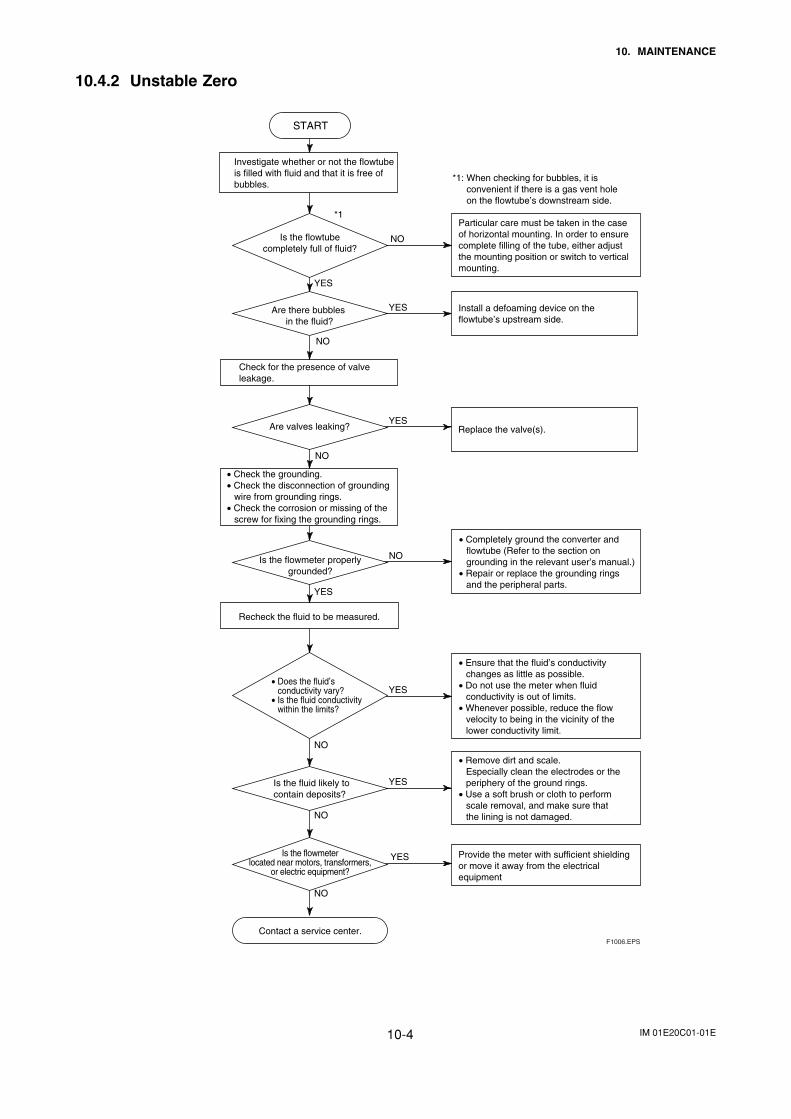
IM 01E20C01-01E10-4
10. MAINTENANCE
10.4.2 Unstable Zero
START
Check for the presence of valve leakage.
Recheck the fluid to be measured.
Particular care must be taken in the case of horizontal mounting. In order to ensure complete filling of the tube, either adjust the mounting position or switch to vertical mounting.
• Ensure that the fluid’s conductivity changes as little as possible.
• Do not use the meter when fluid conductivity is out of limits.
• Whenever possible, reduce the flow velocity to being in the vicinity of the lower conductivity limit.
• Check the grounding.• Check the disconnection of grounding
wire from grounding rings.• Check the corrosion or missing of the
screw for fixing the grounding rings.
• Remove dirt and scale. Especially clean the electrodes or the periphery of the ground rings.
• Use a soft brush or cloth to perform scale removal, and make sure that the lining is not damaged.
• Completely ground the converter and flowtube (Refer to the section on grounding in the relevant user’s manual.)
• Repair or replace the grounding rings and the peripheral parts.
Provide the meter with sufficient shielding or move it away from the electrical equipment
NO
NO
NO
NO
NO
NO
NO
YES
YES
YES
YES
YES
YES
YES
Are there bubbles in the fluid?
Are valves leaking?
Is the fluid likely to contain deposits?
• Does the fluid’s conductivity vary?
• Is the fluid conductivitywithin the limits?
Is the flowtubecompletely full of fluid?
Is the flowmeter properlygrounded?
Contact a service center.
*1: When checking for bubbles, it is convenient if there is a gas vent hole on the flowtube’s downstream side.
*1
Investigate whether or not the flowtube is filled with fluid and that it is free of bubbles.
Is the flowmeterlocated near motors, transformers,
or electric equipment?
F1006.EPS
Install a defoaming device on the flowtube’s upstream side.
Replace the valve(s).
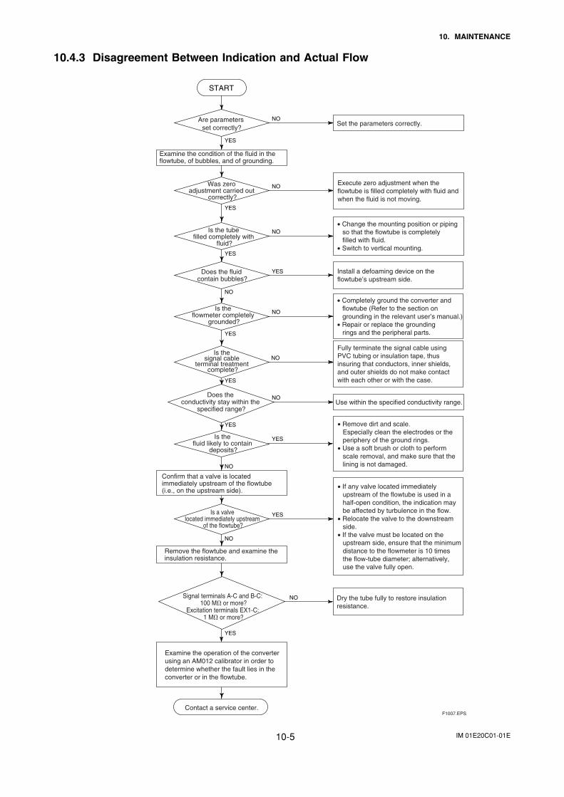
IM 01E20C01-01E10-5
10. MAINTENANCE
10.4.3 Disagreement Between Indication and Actual Flow
NO
NO
NO
NO
YES
NO
NO
YES
YES
YES
NO
YES
YES
NO
NO
YES
Set the parameters correctly.
Examine the condition of the fluid in the flowtube, of bubbles, and of grounding.
Execute zero adjustment when the flowtube is filled completely with fluid and when the fluid is not moving.
• Change the mounting position or piping so that the flowtube is completely filled with fluid.
• Switch to vertical mounting.
Install a defoaming device on the flowtube’s upstream side.
Use within the specified conductivity range.
Confirm that a valve is located immediately upstream of the flowtube (i.e., on the upstream side).
YES
• If any valve located immediately upstream of the flowtube is used in a half-open condition, the indication may be affected by turbulence in the flow.
• Relocate the valve to the downstream side.
• If the valve must be located on the upstream side, ensure that the minimum distance to the flowmeter is 10 times the flow-tube diameter; alternatively, use the valve fully open.
• Remove dirt and scale. Especially clean the electrodes or the periphery of the ground rings.
• Use a soft brush or cloth to perform scale removal, and make sure that the lining is not damaged.
START
Are parameters set correctly?
Is the tube filled completely with
fluid?
Is the flowmeter completely
grounded?
Is the fluid likely to contain
deposits?
Is a valve located immediately upstream
of the flowtube?
Examine the operation of the converter using an AM012 calibrator in order to determine whether the fault lies in the converter or in the flowtube.
Contact a service center.
Is the signal cable
terminal treatment complete?
Fully terminate the signal cable using PVC tubing or insulation tape, thus insuring that conductors, inner shields, and outer shields do not make contact with each other or with the case.
Signal terminals A-C and B-C: 100 M or more?
Excitation terminals EX1-C: 1 M or more?
NO Dry the tube fully to restore insulation resistance.
YES
Was zero adjustment carried out
correctly?
Does the fluid contain bubbles?
F1007.EPS
YES
Does the conductivity stay within the
specified range?
Remove the flowtube and examine the insulation resistance.
• Completely ground the converter and flowtube (Refer to the section on grounding in the relevant user’s manual.)
• Repair or replace the grounding rings and the peripheral parts.
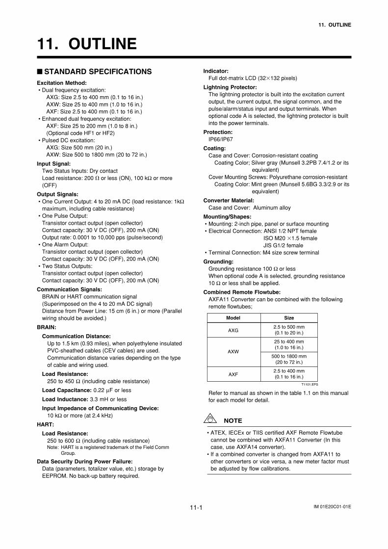
IM 01E20C01-01E11-1
11. OUTLINE
Indicator:Full dot-matrix LCD (32132 pixels)
Lightning Protector:The lightning protector is built into the excitation currentoutput, the current output, the signal common, and thepulse/alarm/status input and output terminals. Whenoptional code A is selected, the lightning protector is builtinto the power terminals.
Protection:IP66/IP67
Coating:Case and Cover: Corrosion-resistant coating
Coating Color; Silver gray (Munsell 3.2PB 7.4/1.2 or itsequivalent)
Cover Mounting Screws: Polyurethane corrosion-resistantCoating Color: Mint green (Munsell 5.6BG 3.3/2.9 or its
equivalent)
Converter Material:Case and Cover: Aluminum alloy
Mounting/Shapes:• Mounting: 2-inch pipe, panel or surface mounting• Electrical Connection: ANSI 1/2 NPT female
ISO M20 1.5 femaleJIS G1/2 female
• Terminal Connection: M4 size screw terminal
Grounding:Grounding resistance 100 Ω or lessWhen optional code A is selected, grounding resistance10 Ω or less shall be applied.
Combined Remote Flowtube:AXFA11 Converter can be combined with the followingremote flowtubes;
T1101.EPS
SizeModel
2.5 to 500 mm(0.1 to 20 in.)
25 to 400 mm(1.0 to 16 in.)
500 to 1800 mm(20 to 72 in.)
2.5 to 400 mm(0.1 to 16 in.)
AXG
AXW
AXF
Refer to manual as shown in the table 1.1 on this manualfor each model for detail.
NOTE
• ATEX, IECEx or TIIS certified AXF Remote Flowtubecannot be combined with AXFA11 Converter (In thiscase, use AXFA14 converter).
• If a combined converter is changed from AXFA11 toother converters or vice versa, a new meter factor mustbe adjusted by flow calibrations.
STANDARD SPECIFICATIONSExcitation Method:• Dual frequency excitation:
AXG: Size 2.5 to 400 mm (0.1 to 16 in.)AXW: Size 25 to 400 mm (1.0 to 16 in.)AXF: Size 2.5 to 400 mm (0.1 to 16 in.)
• Enhanced dual frequency excitation:AXF: Size 25 to 200 mm (1.0 to 8 in.)(Optional code HF1 or HF2)
• Pulsed DC excitation:AXG: Size 500 mm (20 in.)AXW: Size 500 to 1800 mm (20 to 72 in.)
Input Signal:Two Status Inputs: Dry contactLoad resistance: 200 or less (ON), 100 kΩ or more(OFF)
Output Signals:• One Current Output: 4 to 20 mA DC (load resistance: 1kΩ
maximum, including cable resistance)• One Pulse Output:
Transistor contact output (open collector)Contact capacity: 30 V DC (OFF), 200 mA (ON)Output rate: 0.0001 to 10,000 pps (pulse/second)
• One Alarm Output:Transistor contact output (open collector)Contact capacity: 30 V DC (OFF), 200 mA (ON)
• Two Status Outputs:Transistor contact output (open collector)Contact capacity: 30 V DC (OFF), 200 mA (ON)
Communication Signals:BRAIN or HART communication signal(Superimposed on the 4 to 20 mA DC signal)Distance from Power Line: 15 cm (6 in.) or more (Parallelwiring should be avoided.)
BRAIN:
Communication Distance:Up to 1.5 km (0.93 miles), when polyethylene insulatedPVC-sheathed cables (CEV cables) are used.Communication distance varies depending on the typeof cable and wiring used.
Load Resistance:250 to 450 Ω (including cable resistance)
Load Capacitance: 0.22 µF or less
Load Inductance: 3.3 mH or less
Input Impedance of Communicating Device:10 kΩ or more (at 2.4 kHz)
HART:
Load Resistance:250 to 600 Ω (including cable resistance)Note: HART is a registered trademark of the Field Comm
Group.
Data Security During Power Failure:Data (parameters, totalizer value, etc.) storage byEEPROM. No back-up battery required.
11. OUTLINE
IM 01E20C01-01E11-2
11. OUTLINE
Functions
How to Set Parameters:The indicator’s LCD and three infra-red switches enableusers to set parameters without opening the case cover.Parameters can also be set with the configulation tool(Such as HHT (handheld terminal) or FieldMate, etc.).The language for the HHT is English only.
Displayed Languages:Users can choose a language from among English,Japanese, German, French, Italian, Spanish.
Instantaneous Flow Rate/Totalized Value DisplayFunctions:
The full dot-matrix LCD enables user selections ofdisplays from one line to three lines for:
• Instantaneous flow rate• Instantaneous flow rate (%)• Instantaneous flow rate (bar graph)• Current output value (mA)• Totalized forward-direction flow rate• Totalized reverse-direction flow rate• Totalized differential flow rate• Tag No.• Results of electrode adhesion diagnostics• Communication type
Totalizer Display Function:The flow rate is counted one pulse at a time according tothe setting of totalization pulse weights. For forward andreverse flow measurement functions, the totalized valuesof the flow direction (forward or reverse) and the flowdirection are displayed on the indicator together with theunits. The difference of totalized values between theforward and reverse flow rate can be displayed. Totaliza-tion for the reverse flow rate is carried out only when“Forward and reverse flow measurement functions” isselected.
Damping Time Constant:Time constant can be set from 0.1 second to 200.0seconds (63% response). The default is 3 seconds.
Span Setting Function:Span flows can be set in units such as volume flow rate,mass flow rate, time, or flow rate value. The velocity unitcan also be set.Volume Flow Rate Unit: kcf, cf, mcf, Mgal (US), kgal (US),
gal (US), mgal (US), kbbl (US)*, bbl (US)*,mbbl (US)*, µbbl (US)*, Ml (megaliter), m3, kl(kiloliter), l (liter), cm3
Mass Flow Rate Unit (Density must be set.): klb (US), lb(US), t (ton), kg, g
Velocity Unit: ft, m (meter)Time Unit: s (sec), min, h (hour), d (day)
* “US Oil” or “US Beer” can be selected.
Pulse Output:Scaled pulse can be output by setting a pulse weight.Pulse Width:Duty 50% or fixed pulse width (0.05, 0.1, 0.5,
1, 20, 33, 50, 100 ms) can be selected.Output Rate:0.0001 to 10,000 pps (pulse/second)
Multi-range Function:• Range switching via status input
Status input enables the switching of up to four ranges.• Automatic range switching
When the flow rate exceeds 100 % of the range,transition to the next range (up to four ranges) is carriedout automatically. Range switching can be confirmed bystatus outputs and indicator.
Forward and Reverse Flow Measurement Functions:Flows in both forward and reverse directions can bemeasured. The reverse flow measurement can beconfirmed by status output and indicator.
Totalization Switch:The status output is carried out when a totalized valuebecomes equal to or greater than the set value.
Preset Totalization:The parameter setting or status input enables a totalizedvalue to be preset to a setting value or zero.
0% Signal Lock:Status input forcibly fixes the instantaneous flow ratedisplay, current output, pulse output, and flow ratetotalization to 0%.
Alarm Selection Function:Alarms are classified into System Alarms (hard failures),Process Alarms (such as ‘Empty Pipe’, ‘Signal Overflow’and ‘Adhesion Alarm’), Setting Alarms, and Warnings.Whether alarms should be generated or not can beselected for each item.The current output generated for an alarm can beselected from among 2.4 mA or less, fixed to 4 mA, 21.6mA or more, or HOLD.
Alarm Output:Alarms are generated only for the items selected via the‘Alarm Selection Function’ if relevant failures occur.
Self Diagnostics Functions:If alarms are generated, details of the System Alarms,Process Alarms, Setting Alarms and Warnings aredisplayed together with concrete descriptions of counter-measures.
Flow Upper/Lower Limit Alarms:If a flow rate becomes greater or smaller than the setvalue, this alarm is generated. In addition, two upper limits(H, HH) and two lower limits (L, LL) can be set.If a flow rate becomes greater or smaller than any of theset values, the status is output.
Electrode Adhesion Diagnostics Function:This function enables monitoring of the adhesion level ofinsulating substances to the electrodes. Depending on thestatus of adhesion, users are notified by a warning or analarm via status outputs.
IM 01E20C01-01E11-3
11. OUTLINE
Combined with AXW Remote Flowtube
For AXW Remote Flowtube (up to 400 mm (16 in.))
Safety Requirement Standards:EN61010-1EN61010-2-030CAN/CSA-C22.2 No.61010-1-12CAN/CSA-C22.2 No.61010-2-30-12CAN/CSA-C22.2 No.94.02-07UL 61010-1 (3rd Edition)UL 61010-2-030 (1st Edition)UL 50EIEC 60529
• Altitude at Installation Site: Max. 2000 mAbove sea level
• Installation Category (Overvoltage category): II• Micro Pollution Degree: 2• Macro Pollution Degree: 4• Protection Degree:
IP66/67, Type 4X (CSA)
EMC:EN61326-1 Class A, Table 2 (For use in industriallocations)EN61326-2-3EN61000-3-2 Class AEN61000-3-3
For AXFA11 Remote Converter
Safety Requirement Standards:EN61010-1EN61010-2-030
• Altitude at installation site: Max. 2000 m above sea level• Installation category based on IEC1010:
Overvoltage category II (“II” applies to electrical equip-ment which is supplied from a fixed installation-likedistribution board.)
• Pollution degree based on IEC1010Pollution degree 2 (“Pollution degree” describes thedegree to which a solid, liquid, or gas which deterioratesdielectric strength or surface resistivity is adhering. “2”applies to a normal indoor atmosphere.)
EMC:EN61326-1 Class A, Table 2 (For use in industriallocations)EN61326-2-3EN61000-3-2 Class AEN61000-3-3
NOTE
This instrument is an EN61326-1 (EMC standard), Class A(for use in commercial, industrial, or business environ-ments). The influence rate (judgment condition A) in theimmunity test environment is within 5% of default (1 m/s)span.
CONFORMITY STANDARDS ()
Combined with AXG Remote Flowtube
For AXG Remote Flowtube (up to 400 mm (16 in.))
Safety Requirement Standards:EN61010-1EN61010-2-030CAN/CSA-C22.2 No.61010-1-12CAN/CSA-C22.2 No.61010-2-30-12CAN/CSA-C22.2 No.94.02-07UL 61010-1 (3rd Edition)UL 61010-2-030 (1st Edition)UL 50EIEC 60529
• Altitude at Installation Site: Max. 2000 mAbove sea level
• Installation Category (Overvoltage category): II• Micro Pollution Degree: 2• Macro Pollution Degree: 4• Protection Degree:
IP66/67, Type 4X (CSA)
EMC:EN61326-1 Class A, Table 2 (For use in industriallocations)EN61326-2-3EN61000-3-2 Class AEN61000-3-3
For AXFA11 Remote Converter
Safety Requirement Standards:EN61010-1EN61010-2-030
• Altitude at installation site: Max. 2000 m above sea level• Installation category based on IEC1010:
Overvoltage category II (“II” applies to electrical equip-ment which is supplied from a fixed installation-likedistribution board.)
• Pollution degree based on IEC1010Pollution degree 2 (“Pollution degree” describes thedegree to which a solid, liquid, or gas which deterioratesdielectric strength or surface resistivity is adhering. “2”applies to a normal indoor atmosphere.)
EMC:EN61326-1 Class A, Table 2 (For use in industriallocations)EN61326-2-3EN61000-3-2 Class AEN61000-3-3
NOTE
This instrument is an EN61326-1 (EMC standard), Class A(for use in commercial, industrial, or business environ-ments). The influence rate (judgment condition A) in theimmunity test environment is within 5% of default (1 m/s)span.
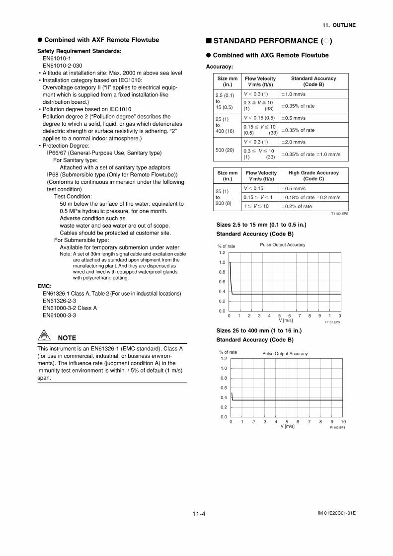
IM 01E20C01-01E11-4
11. OUTLINE
Combined with AXF Remote Flowtube
Safety Requirement Standards:EN61010-1EN61010-2-030
• Altitude at installation site: Max. 2000 m above sea level• Installation category based on IEC1010:
Overvoltage category II (“II” applies to electrical equip-ment which is supplied from a fixed installation-likedistribution board.)
• Pollution degree based on IEC1010Pollution degree 2 (“Pollution degree” describes thedegree to which a solid, liquid, or gas which deterioratesdielectric strength or surface resistivity is adhering. “2”applies to a normal indoor atmosphere.)
• Protection Degree:IP66/67 (General-Purpose Use, Sanitary type) For Sanitary type:
Attached with a set of sanitary type adaptorsIP68 (Submersible type (Only for Remote Flowtube))(Conforms to continuous immersion under the followingtest condition) Test Condition:
50 m below the surface of the water, equivalent to0.5 MPa hydraulic pressure, for one month.Adverse condition such aswaste water and sea water are out of scope.Cables should be protected at customer site.
For Submersible type:Available for temporary submersion under waterNote: A set of 30m length signal cable and excitation cable
are attached as standard upon shipment from themanufacturing plant. And they are dispensed aswired and fixed with equipped waterproof glandswith polyurethane potting.
EMC:EN61326-1 Class A, Table 2 (For use in industrial locations)EN61326-2-3EN61000-3-2 Class AEN61000-3-3
NOTE
This instrument is an EN61326-1 (EMC standard), Class A(for use in commercial, industrial, or business environ-ments). The influence rate (judgment condition A) in theimmunity test environment is within 5% of default (1 m/s)span.
STANDARD PERFORMANCE ()
Combined with AXG Remote Flowtube
Accuracy:
Size mm(in.)
V 0.3 (1) 1.0 mm/s
0.3 V 10(1) (33) 0.35% of rate
2.5 (0.1)to 15 (0.5)
V 0.15 (0.5) 0.5 mm/s
0.15 V 10(0.5) (33) 0.35% of rate
25 (1)to 400 (16)
V 0.3 (1) 2.0 mm/s
0.3 V 10(1) (33) 0.35% of rate 1.0 mm/s
500 (20)
Flow VelocityV m/s (ft/s)
Standard Accuracy(Code B)
Size mm(in.)
V 0.15 0.5 mm/s
0.15 V 1 0.18% of rate 0.2 mm/s
1 V 10 0.2% of rate
25 (1)to 200 (8)
Flow VelocityV m/s (ft/s)
High Grade Accuracy(Code C)
T1102.EPS
Sizes 2.5 to 15 mm (0.1 to 0.5 in.)
Standard Accuracy (Code B)
0.0
0.2
0.4
0.6
0.8
1.0
1.2
0 1 2 3 4 5 6 7 8 9 1 0
% of rate
V [m/s] F1101.EPS
Pulse Output Accuracy
Sizes 25 to 400 mm (1 to 16 in.)
Standard Accuracy (Code B)
0.0
0.2
0.4
0.6
0.8
1.0
1.2
0 1 2 3 4 5 6 7 8 9 10
% of rate
V [m/s]
Pulse Output Accuracy
F1102.EPS
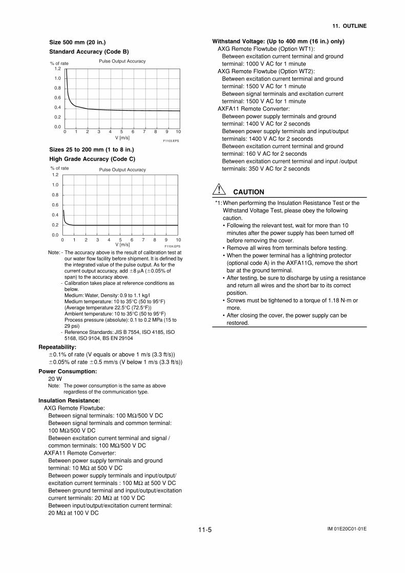
IM 01E20C01-01E11-5
11. OUTLINE
Size 500 mm (20 in.)
Standard Accuracy (Code B)
F1103.EPS
0.0
0.2
0.4
0.6
0.8
1.0
1.2
0 1 2 3 4 5 6 7 8 9 10
% of rate
V [m/s]
Pulse Output Accuracy
Sizes 25 to 200 mm (1 to 8 in.)
High Grade Accuracy (Code C)
0.0
0.2
0.4
0.6
0.8
1.0
1.2
0 1 2 3 4 5 6 7 8 9 10
% of rate
V [m/s]
Pulse Output Accuracy
F1104.EPS
Note: - The accuracy above is the result of calibration test atour water flow facility before shipment. It is defined bythe integrated value of the pulse output. As for thecurrent output accuracy, add 8 µA (0.05% ofspan) to the accuracy above.
- Calibration takes place at reference conditions asbelow.Medium: Water, Density: 0.9 to 1.1 kg/lMedium temperature: 10 to 35°C (50 to 95°F)(Average temperature 22.5°C (72.5°F))Ambient temperature: 10 to 35°C (50 to 95°F)Process pressure (absolute): 0.1 to 0.2 MPa (15 to29 psi)
- Reference Standards: JIS B 7554, ISO 4185, ISO5168, ISO 9104, BS EN 29104
Repeatability:0.1% of rate (V equals or above 1 m/s (3.3 ft/s))0.05% of rate 0.5 mm/s (V below 1 m/s (3.3 ft/s))
Power Consumption:20 WNote: The power consumption is the same as above
regardless of the communication type.
Insulation Resistance:AXG Remote Flowtube:
Between signal terminals: 100 MΩ/500 V DCBetween signal terminals and common terminal:100 MΩ/500 V DCBetween excitation current terminal and signal /common terminals: 100 MΩ/500 V DC
AXFA11 Remote Converter:Between power supply terminals and groundterminal: 10 MΩ at 500 V DCBetween power supply terminals and input/output/excitation current terminals : 100 MΩ at 500 V DCBetween ground terminal and input/output/excitationcurrent terminals: 20 MΩ at 100 V DCBetween input/output/excitation current terminal:20 MΩ at 100 V DC
Withstand Voltage: (Up to 400 mm (16 in.) only)AXG Remote Flowtube (Option WT1):
Between excitation current terminal and groundterminal: 1000 V AC for 1 minute
AXG Remote Flowtube (Option WT2):Between excitation current terminal and groundterminal: 1500 V AC for 1 minuteBetween signal terminals and excitation currentterminal: 1500 V AC for 1 minute
AXFA11 Remote Converter:Between power supply terminals and groundterminal: 1400 V AC for 2 secondsBetween power supply terminals and input/outputterminals: 1400 V AC for 2 secondsBetween excitation current terminal and groundterminal: 160 V AC for 2 secondsBetween excitation current terminal and input /outputterminals: 350 V AC for 2 seconds
CAUTION
*1: When performing the Insulation Resistance Test or theWithstand Voltage Test, please obey the followingcaution.• Following the relevant test, wait for more than 10
minutes after the power supply has been turned offbefore removing the cover.
• Remove all wires from terminals before testing.• When the power terminal has a lightning protector
(optional code A) in the AXFA11G, remove the shortbar at the ground terminal.
• After testing, be sure to discharge by using a resistanceand return all wires and the short bar to its correctposition.
• Screws must be tightened to a torque of 1.18 N-m ormore.
• After closing the cover, the power supply can berestored.
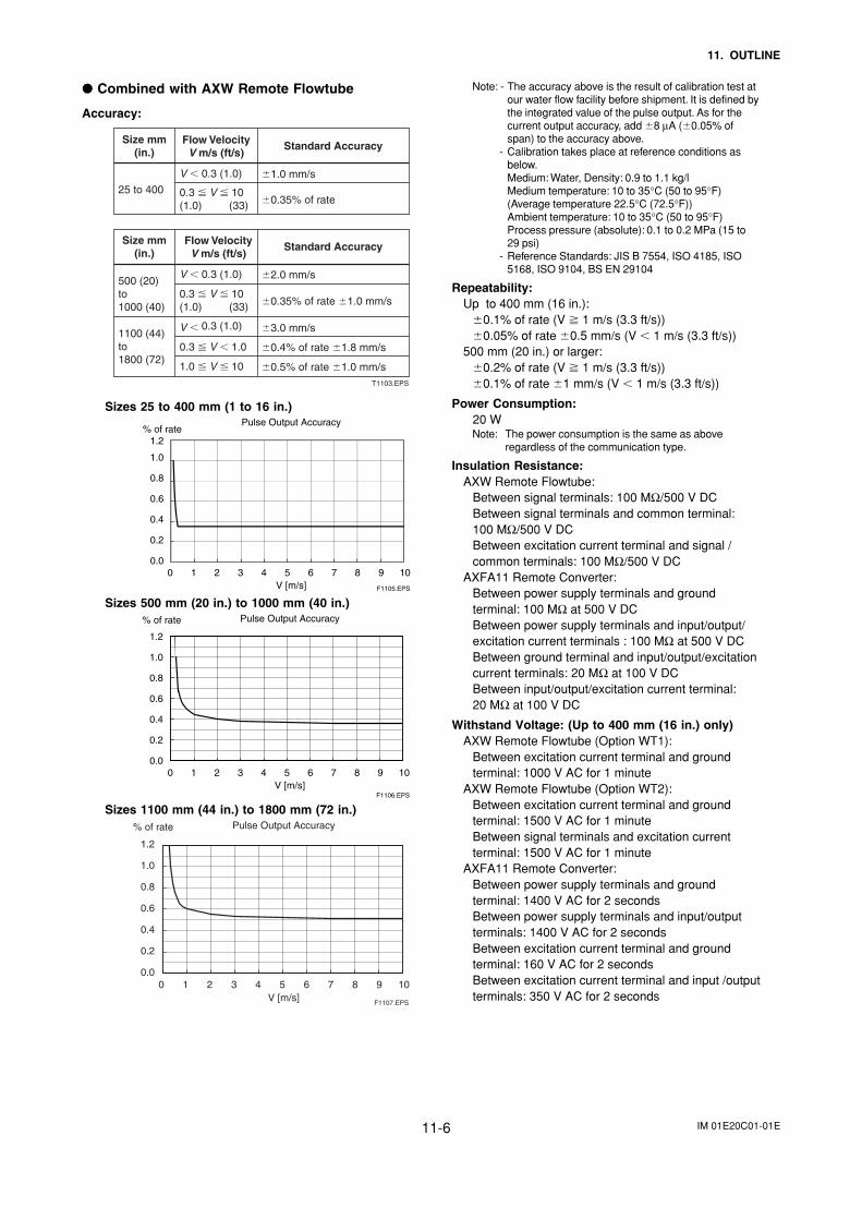
IM 01E20C01-01E11-6
11. OUTLINE
Combined with AXW Remote Flowtube
Accuracy:
Size mm(in.)
V 0.3 (1.0) 1.0 mm/s
0.3 V 10(1.0) (33) 0.35% of rate
0.3 V 10(1.0) (33) 0.35% of rate 1.0 mm/s
25 to 400
Flow VelocityV m/s (ft/s)
Standard Accuracy
Size mm(in.)
V 0.3 (1.0) 2.0 mm/s
0.3 V 1.0 0.4% of rate 1.8 mm/s
V 0.3 (1.0) 3.0 mm/s
1.0 V 10 0.5% of rate 1.0 mm/s
500 (20)to 1000 (40)
1100 (44)to 1800 (72)
Flow VelocityV m/s (ft/s)
Standard Accuracy
T1103.EPS
Sizes 25 to 400 mm (1 to 16 in.)Pulse Output Accuracy
0.0
0.2
0.4
0.6
0.8
1.0
1.2
0 1 2 3 4 5 6 7 8 9 10V [m/s]
% of rate
F1105.EPS
Sizes 500 mm (20 in.) to 1000 mm (40 in.)Pulse Output Accuracy
0.0
F1106.EPS
0.2
0.4
0.6
0.8
1.0
1.2
0 1 2 3 4 5 6 7 8 9 10V [m/s]
% of rate
Sizes 1100 mm (44 in.) to 1800 mm (72 in.)
F1107.EPS
Pulse Output Accuracy
0.0
0.2
0.4
0.6
0.8
1.0
1.2
0 1 2 3 4 5 6 7 8 9 10V [m/s]
% of rate
Note: - The accuracy above is the result of calibration test atour water flow facility before shipment. It is defined bythe integrated value of the pulse output. As for thecurrent output accuracy, add 8 µA (0.05% ofspan) to the accuracy above.
- Calibration takes place at reference conditions asbelow.Medium: Water, Density: 0.9 to 1.1 kg/lMedium temperature: 10 to 35°C (50 to 95°F)(Average temperature 22.5°C (72.5°F))Ambient temperature: 10 to 35°C (50 to 95°F)Process pressure (absolute): 0.1 to 0.2 MPa (15 to29 psi)
- Reference Standards: JIS B 7554, ISO 4185, ISO5168, ISO 9104, BS EN 29104
Repeatability:Up to 400 mm (16 in.):
0.1% of rate (V 1 m/s (3.3 ft/s))0.05% of rate 0.5 mm/s (V 1 m/s (3.3 ft/s))
500 mm (20 in.) or larger:0.2% of rate (V 1 m/s (3.3 ft/s))0.1% of rate 1 mm/s (V 1 m/s (3.3 ft/s))
Power Consumption:20 WNote: The power consumption is the same as above
regardless of the communication type.
Insulation Resistance:AXW Remote Flowtube:
Between signal terminals: 100 MΩ/500 V DCBetween signal terminals and common terminal:100 MΩ/500 V DCBetween excitation current terminal and signal /common terminals: 100 MΩ/500 V DC
AXFA11 Remote Converter:Between power supply terminals and groundterminal: 100 MΩ at 500 V DCBetween power supply terminals and input/output/excitation current terminals : 100 MΩ at 500 V DCBetween ground terminal and input/output/excitationcurrent terminals: 20 MΩ at 100 V DCBetween input/output/excitation current terminal:20 MΩ at 100 V DC
Withstand Voltage: (Up to 400 mm (16 in.) only)AXW Remote Flowtube (Option WT1):
Between excitation current terminal and groundterminal: 1000 V AC for 1 minute
AXW Remote Flowtube (Option WT2):Between excitation current terminal and groundterminal: 1500 V AC for 1 minuteBetween signal terminals and excitation currentterminal: 1500 V AC for 1 minute
AXFA11 Remote Converter:Between power supply terminals and groundterminal: 1400 V AC for 2 secondsBetween power supply terminals and input/outputterminals: 1400 V AC for 2 secondsBetween excitation current terminal and groundterminal: 160 V AC for 2 secondsBetween excitation current terminal and input /outputterminals: 350 V AC for 2 seconds
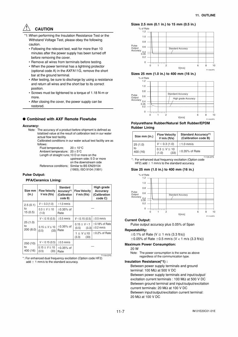
IM 01E20C01-01E11-7
11. OUTLINE
CAUTION
*1:When performing the Insulation Resistance Test or theWithstand Voltage Test, please obey the followingcaution.• Following the relevant test, wait for more than 10
minutes after the power supply has been turned offbefore removing the cover.
• Remove all wires from terminals before testing.• When the power terminal has a lightning protector
(optional code A) in the AXFA11G, remove the shortbar at the ground terminal.
• After testing, be sure to discharge by using a resistanceand return all wires and the short bar to its correctposition.
• Screws must be tightened to a torque of 1.18 N-m ormore.
• After closing the cover, the power supply can berestored.
Combined with AXF Remote Flowtube
Accuracy:Note: The accuracy of a product before shipment is defined as
totalized value at the result of calibration test in our wateractual flow test facility.Calibrated conditions in our water actual test facility are asfollows:
Fluid temperature; 20 ± 10°CAmbient temperature; 20 ± 5°CLength of straight runs;10 D or more on the
upstream side; 5 D or moreon the downstream side
Reference conditions; Similar to BS EN29104(1993); ISO 9104 (1991)
Pulse Output:
PFA/Ceramics Lining:
Size mm (in.)
V 0.3 (1.0) 1.0 mm/s
0.5 mm/s 0.5 mm/s
0.3 V 10 (1.0)
V 0.15 (0.5)
V 0.15 (0.5)
0.15 V 10(0.5) (33)
0.15 V 10(0.5) (33)
V 0.15 (0.5)
0.15 V 1 (0.5) (3.3)
0.35% of Rate
0.5 mm/s
0.35% of Rate
0.35% of Rate
2.5 (0.1) to 15 (0.5)
250 (10) to 400 (16)
25 (1.0) to 200 (8.0)
—
—
Flow VelocityV m/s (ft/s)
Flow VelocityV m/s (ft/s)
Standard Accuracy(*) (Calibration
code B)
High grade Accuracy
(Calibration code C)
0.18% of Rate 0.2 mm/s
1 V 10 (3.3) (33)
0.2% of Rate
T1104.EPS
*: For enhanced dual frequency excitation (Option code HF2)add 1 mm/s to the standard accuracy.
Sizes 2.5 mm (0.1 in.) to 15 mm (0.5 in.)
1.2
1.0
0.8
0.6
0.40.35
0.2
00 1 2 6 8 10
V[m/s]
High grade AccuracyHigh grade AccuracyStandard Accuracy
F1108.EPS
PulseOutputAccuracy
% of Rate
Sizes 25 mm (1.0 in.) to 400 mm (16 in.)
1.2
1.0
0.8
0.6
0.40.35
0.2
00 1 2 6 8 10
V[m/s]F1109.EPS
PulseOutputAccuracy
% of Rate
Standard Accuracy
High grade Accuracy
Polyurethane Rubber/Natural Soft Rubber/EPDMRubber Lining
Size mm (in.)
V 0.3 (1.0) 1.0 mm/s
0.3 V 10(1.0) (33) 0.35% of Rate
25 (1.0)to 400 (16)
Flow VelocityV m/s (ft/s)
Standard Accuracy(*) (Calibration code B)
T1105.EPS*: For enhanced dual frequency excitation (Option code
HF2) add 1 mm/s to the standard accuracy.
Size 25 mm (1.0 in.) to 400 mm (16 in.)
1.2
1.0
0.8
0.6
0.40.35
0.2
00 1 2 6 8 10
V[m/s]
High grade AccuracyHigh grade AccuracyStandard Accuracy
F1110.EPS
PulseOutputAccuracy
% of Rate
Current Output:Pulse output accuracy plus 0.05% of Span
Repeatability:0.1% of Rate (V 1 m/s (3.3 ft/s))0.05% of Rate 0.5 mm/s (V < 1 m/s (3.3 ft/s))
Maximum Power Consumption:20 WNote: The power consumption is the same as above
regardless of the communication type.
Insulation Resistance(*1) :Between power supply terminals and groundterminal: 100 MΩ at 500 V DCBetween power supply terminals and input/output/excitation current terminals : 100 MΩ at 500 V DCBetween ground terminal and input/output/excitationcurrent terminals: 20 MΩ at 100 V DCBetween input/output/excitation current terminal:20 MΩ at 100 V DC
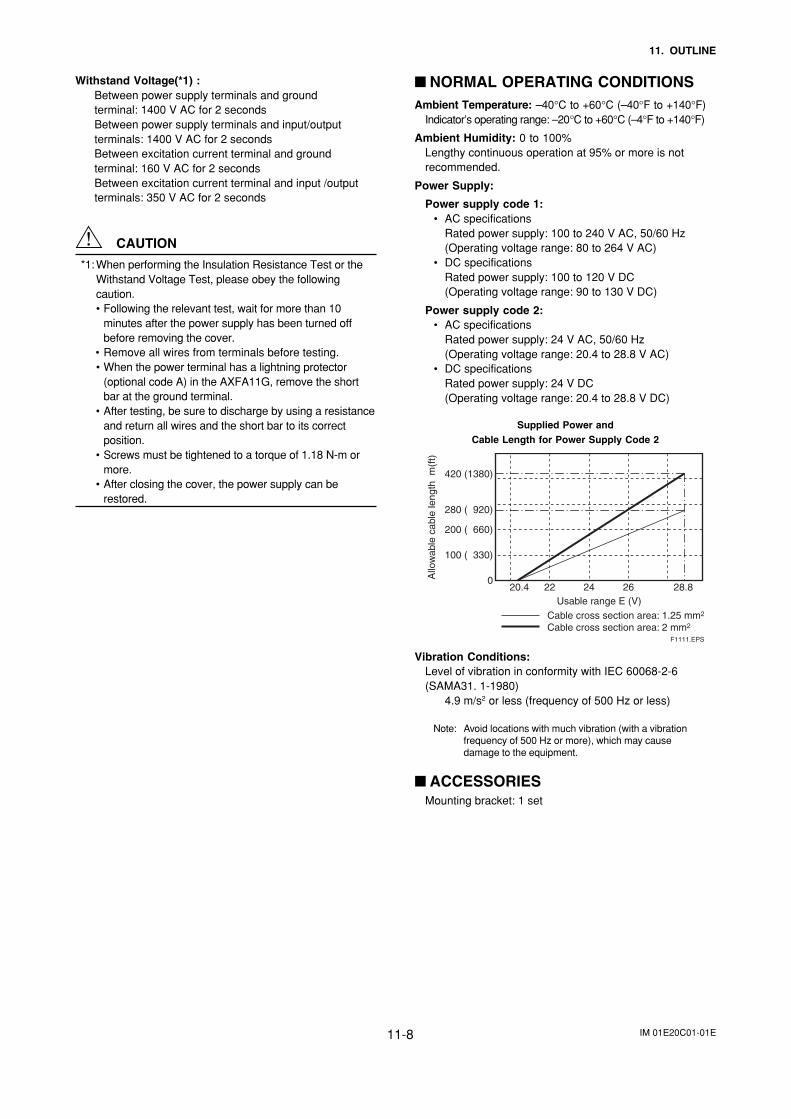
IM 01E20C01-01E11-8
11. OUTLINE
Withstand Voltage(*1) :Between power supply terminals and groundterminal: 1400 V AC for 2 secondsBetween power supply terminals and input/outputterminals: 1400 V AC for 2 secondsBetween excitation current terminal and groundterminal: 160 V AC for 2 secondsBetween excitation current terminal and input /outputterminals: 350 V AC for 2 seconds
CAUTION
*1: When performing the Insulation Resistance Test or theWithstand Voltage Test, please obey the followingcaution.• Following the relevant test, wait for more than 10
minutes after the power supply has been turned offbefore removing the cover.
• Remove all wires from terminals before testing.• When the power terminal has a lightning protector
(optional code A) in the AXFA11G, remove the shortbar at the ground terminal.
• After testing, be sure to discharge by using a resistanceand return all wires and the short bar to its correctposition.
• Screws must be tightened to a torque of 1.18 N-m ormore.
• After closing the cover, the power supply can berestored.
NORMAL OPERATING CONDITIONSAmbient Temperature: –40°C to +60°C (–40°F to +140°F)
Indicator’s operating range: –20°C to +60°C (–4°F to +140°F)
Ambient Humidity: 0 to 100%Lengthy continuous operation at 95% or more is notrecommended.
Power Supply:
Power supply code 1:• AC specifications
Rated power supply: 100 to 240 V AC, 50/60 Hz(Operating voltage range: 80 to 264 V AC)
• DC specificationsRated power supply: 100 to 120 V DC(Operating voltage range: 90 to 130 V DC)
Power supply code 2:• AC specifications
Rated power supply: 24 V AC, 50/60 Hz(Operating voltage range: 20.4 to 28.8 V AC)
• DC specificationsRated power supply: 24 V DC(Operating voltage range: 20.4 to 28.8 V DC)
Supplied Power andCable Length for Power Supply Code 2
020.4 22 24 26 28.8
100 ( 330)
200 ( 660)
280 ( 920)
420 (1380)
F1111.EPS
Cable cross section area: 1.25 mm2
Cable cross section area: 2 mm2
Allo
wab
le c
able
leng
th m
(ft)
Usable range E (V)
Vibration Conditions:Level of vibration in conformity with IEC 60068-2-6(SAMA31. 1-1980)
4.9 m/s2 or less (frequency of 500 Hz or less)
Note: Avoid locations with much vibration (with a vibrationfrequency of 500 Hz or more), which may causedamage to the equipment.
ACCESSORIESMounting bracket: 1 set
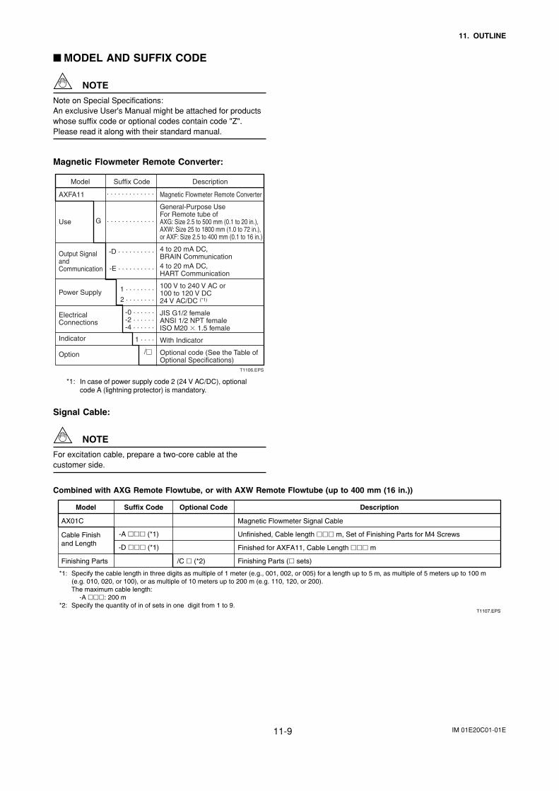
IM 01E20C01-01E11-9
11. OUTLINE
MODEL AND SUFFIX CODE
NOTE
Note on Special Specifications:An exclusive User's Manual might be attached for productswhose suffix code or optional codes contain code "Z".Please read it along with their standard manual.
Magnetic Flowmeter Remote Converter:
Model Suffix Code Description
AXFA11
Use
Output SignalandCommunication
Power Supply
ElectricalConnections
Indicator
Option
Magnetic Flowmeter Remote Converter
General-Purpose UseFor Remote tube ofAXG: Size 2.5 to 500 mm (0.1 to 20 in.),AXW: Size 25 to 1800 mm (1.0 to 72 in.),or AXF: Size 2.5 to 400 mm (0.1 to 16 in.)
4 to 20 mA DC, BRAIN Communication4 to 20 mA DC, HART Communication
100 V to 240 V AC or 100 to 120 V DC24 V AC/DC (*1)
JIS G1/2 femaleANSI 1/2 NPT femaleISO M20 1.5 female
With Indicator
Optional code (See the Table of Optional Specifications)
· · · · · · · · · · · · ·
-D · · · · · · · · · ·
-E · · · · · · · · · ·
1 · · · · · · · ·
2 · · · · · · · ·
-0 · · · · · ·-2 · · · · · ·-4 · · · · · ·
1 · · · ·
/
T1106.EPS
· · · · · · · · · · · · ·
G
*1: In case of power supply code 2 (24 V AC/DC), optionalcode A (lightning protector) is mandatory.
Signal Cable:
NOTE
For excitation cable, prepare a two-core cable at thecustomer side.
Combined with AXG Remote Flowtube, or with AXW Remote Flowtube (up to 400 mm (16 in.))
Model Suffix Code Optional Code Description
/C (*2)
Magnetic Flowmeter Signal Cable
Unfinished, Cable length m, Set of Finishing Parts for M4 Screws
Finished for AXFA11, Cable Length m
Finishing Parts ( sets)
T1107.EPS
AX01C
Cable Finish and Length
Finishing Parts
-A (*1)
-D (*1)
*1: Specify the cable length in three digits as multiple of 1 meter (e.g., 001, 002, or 005) for a length up to 5 m, as multiple of 5 meters up to 100 m(e.g. 010, 020, or 100), or as multiple of 10 meters up to 200 m (e.g. 110, 120, or 200). The maximum cable length:
-A : 200 m*2: Specify the quantity of in of sets in one digit from 1 to 9.
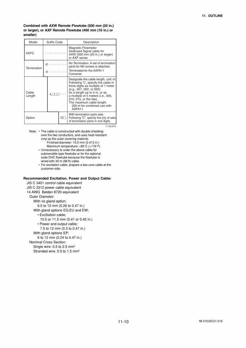
IM 01E20C01-01E11-10
11. OUTLINE
Combined with AXW Remote Flowtube (500 mm (20 in.)or larger), or AXF Remote Flowtube (400 mm (16 in.) orsmaller)
Model Suffix Code Description
AXFC
Termination
Cable Length
Option
Magnetic FlowmeterDedicaed Signal cable for AXW (500 mm (20 in.) or larger) or AXF series
No Termination. A set of termination parts for M4 screws is attached.Terminated for the AXFA11 Converter.
Designate the cable length, unit: mFollowing “L”, specify the cable in three digits as multiple of 1 meter (e.g., 001, 002, or 005) for a length up to 5 m, or as a multiple of 5 meters (i.e., 005, 010, 015, or the like).The maximum cable length:
200 m for combined use with AXFA11
With termination parts sets.Following “C”, specify the q’ty of sets of termination parts in one digits.
· · · · · · · · · · · · ·
-0 · · · · · · · · · · ·
-4 · · · · · · · · · · ·
-L · · · ·
/C
T1108.EPS
Note: • The cable is constructed with double shieldingover the two conductors, and uses heat-resistantvinyl as the outer covering material.
Finished diameter: 10.5 mm (0.413 in.)Maximum temperature: +80˚C (+176˚F)
• Unnecessary to order the above cable forsubmersible type flowtube or for the optionalcode DHC flowtube because the flowtube iswired with 30 m (98 ft) cable.
• For excitation cable, prepare a two-core cable at thecustomer side.
Recommended Excitation, Power and Output Cable:JIS C 3401 control cable equivalentJIS C 3312 power cable equivalent14 AWG Belden 8720 equivalent
Outer Diameter:With no gland option;
6.5 to 12 mm (0.26 to 0.47 in.)With gland options EG,EU and EW;
• Excitiation cable; 10.5 or 11.5 mm (0.41 or 0.45 in.)• Power and output cable; 7.5 to 12 mm (0.3 to 0.47 in.)
With gland options EP;6 to 12 mm (0.24 to 0.47 in.)
Nominal Cross Section:Single wire: 0.5 to 2.5 mm2
Stranded wire: 0.5 to 1.5 mm2
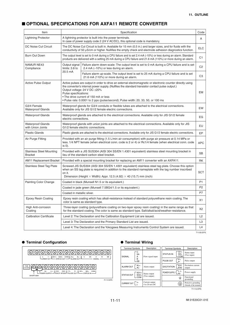
IM 01E20C01-01E11-11
11. OUTLINE
OPTIONAL SPECIFICATIONS FOR AXFA11 REMOTE CONVERTER
Item Specification Code
Burn Out Down
Lightning Protector
DC Noise Cut Circuit
A lightning protector is built into the power terminals.In case of power supply code 2 (24 V AC/DC), this optional code is mandatory.
The output level is set to 0 mA during a CPU failure and is set 2.4 mA (-10%) or less during an alarm. Standard products are delivered with a setting 25 mA during a CPU failure and 21.6 mA (110%) or more during an alarm.
The DC Noise Cut Circuit is built in. Available for 15 mm (0.5 in.) and larger sizes, and for fluids with the conductivity of 50 µS/cm or higher. Nullifies the empty check and electrode adhesion diagnostics function.
NAMUR NE43 Compliance
Output signal limits: 3.8 to 20.5 mA
Failure alarm down-scale: The output level is set to 0 mA during a CPU failure and is set 2.4 mA (–10%) or less during an alarm.
Failure alarm up-scale. The output level is set to 25 mA during a CPU failure and is set 21.6 mA (110%) or more during an alarm.
Active Pulse Output
Waterproof Glands
Active pulses are output in order to drive an external electromagnetic or electronic counter directly using the converter’s internal power supply. (Nullfies the standard transistor contact pulse output.)Output voltage: 24 V DC ±20%Pulse specifications: • The drive current of 150 mA or less• Pulse rate: 0.0001 to 2 pps (pulse/second); Pulse width: 20, 33, 50, or 100 ms
Waterproof glands for G3/4 conduits or flexible tubes are attached to the electrical connections. Available only for JIS G1/2 female electric connections.
Waterproof glands are attached to the electrical connections. Available only for JIS G1/2 female electric connections.
Plastic Glands
Air Purge Fitting
Plastic glands are attached to the electrical connections. Available only for JIS G1/2 female electric connections.
Provided with an air purge fitting (1.5 L/min air consumption) with purge air pressure at 0.14 MPa or less. 1/4 NPT female (when electrical conn. code is 2 or 4) or Rc1/4 female (when electrical conn. code is 0).
Stainless Steel Mounting Bracket
Provided with a JIS SUS304 (AISI 304 SS/EN 1.4301 equivalent) stainless steel mounting bracket in lieu of the standard carbon steel bracket.
AM11 Replacement Bracket Provided with a special mounting bracket for replacing an AM11 converter with an AXFA11.
Calibration Certificate Level 2: The Declaration and the Calibration Equipment List are issued.
Level 3: The Declaration and the Primary Standard List are issued.
Level 4: The Declaration and the Yokogawa Measuring Instruments Control System are issued.
Epoxy Resin Coating Epoxy resin coating which has alkali-resistance instead of standard polyurethane resin coating. The color is same as standard type.
High Anti-corrosion Coating
Three-layer coating (polyurethane coating on two-layer epoxy resin coating) in the same range as that for the standard coating. The color is same as standard type. Salt/alkali/acid/weather-resistance.
Painting Color Change Coated in black (Munsell N1.5 or its equivalent.)
Coated in jade green (Munsell 7.5BG4/1.5 or its equivalent.)
Coated in metallic silver.
Stainless Steel Tag Plate Screwed JIS SUS304 (AISI 304 SS/EN 1.4301 equivalent) stainless steel tag plate. Choose this option when an SS tag plate is required in addition to the standard nameplate with the tag number inscribed on it.Dimension (Height Width): Appr. 12.5 (4.92) 40 (15.7) mm (inch)
G3/4 Female Waterproof Glands
Waterproof glands with union joints are attached to the electrical connections. Available only for JIS G1/2 female electric connections.
Waterproof Glands with Union Joints
A
ELC
C1
C2
C3
EM
EW
EG
EU
EP
APC
SB
RK
SCT
P1
P2
P7
X1
X2
L2
L3
L4
T1109.EPS
Terminal Configuration
I+ I–CURRENT OUT
AL+ AL– C SA A B SBALARM OUT
N/– L/+POWER SUPPLY
EX2EX1EXCIT ATION
P– SI1+ SI2+ COMP+PULSE OUT STATUS IN
SIGNALSO1+ COMSO2+
STATUS OUT
F1112.EPS
SHORT BAR
FUSE2.5A 250V
Terminal Wiring
Terminal Symbols Description
SIGNAL
CURRENT OUT
Flow signal input
Alarm output
Status output(Two output)
Status input(Two input)
Pulse output
Excitation current output
Power supply
Functionalgrounding
Protective grounding(Outside of the terminal)
Current output 4 to 20 mA DC
ALARM OUT
STATUS OUT
Terminal Symbols Description
STATUS IN
POWER SUPPLY
PULSE OUT
EXCITATION
SO1+SO2+COM
CSAABSB
AL+AL-
I+I-
Sl1+Sl2+COM
P+P-
EX1EX2
L /+N/-
T1110.EPS
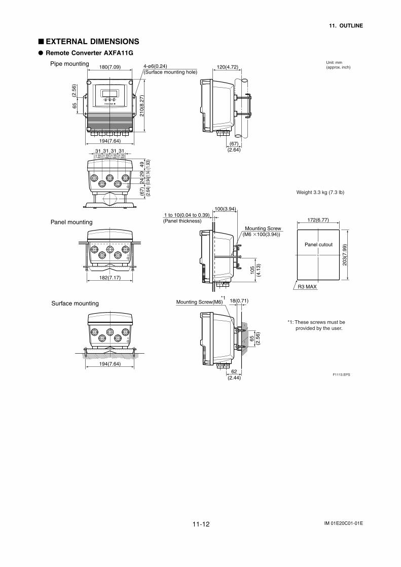
IM 01E20C01-01E11-12
11. OUTLINE
EXTERNAL DIMENSIONS Remote Converter AXFA11G
Pipe mounting120(4.72)180(7.09) 4-ø6(0.24)
(Surface mounting hole)
194(7.64)21
0(8.
27)
65
(67)(2.64)
194(7.64)
182(7.17)
Panel mounting
100(3.94)1 to 10(0.04 to 0.39)
(Panel thickness)
Mounting Screw(M6 100(3.94))
172(6.77)
R3 MAX
203(
7.99
)Panel cutout
62
18(0.71)Mounting Screw(M6)Surface mounting
F1113.EPS
(2.5
6)
(2.44)
105
(4.1
3)65
(2.5
6)
(67)
(2.6
4)49 (1.9
3)29 (1.
14)
24 (0.94
)31(1.22)
31(1.22)
31(1.22)
31(1.22)
Unit: mm(approx. inch)
Weight 3.3 kg (7.3 lb)
*1
*1: These screws must be provided by the user.
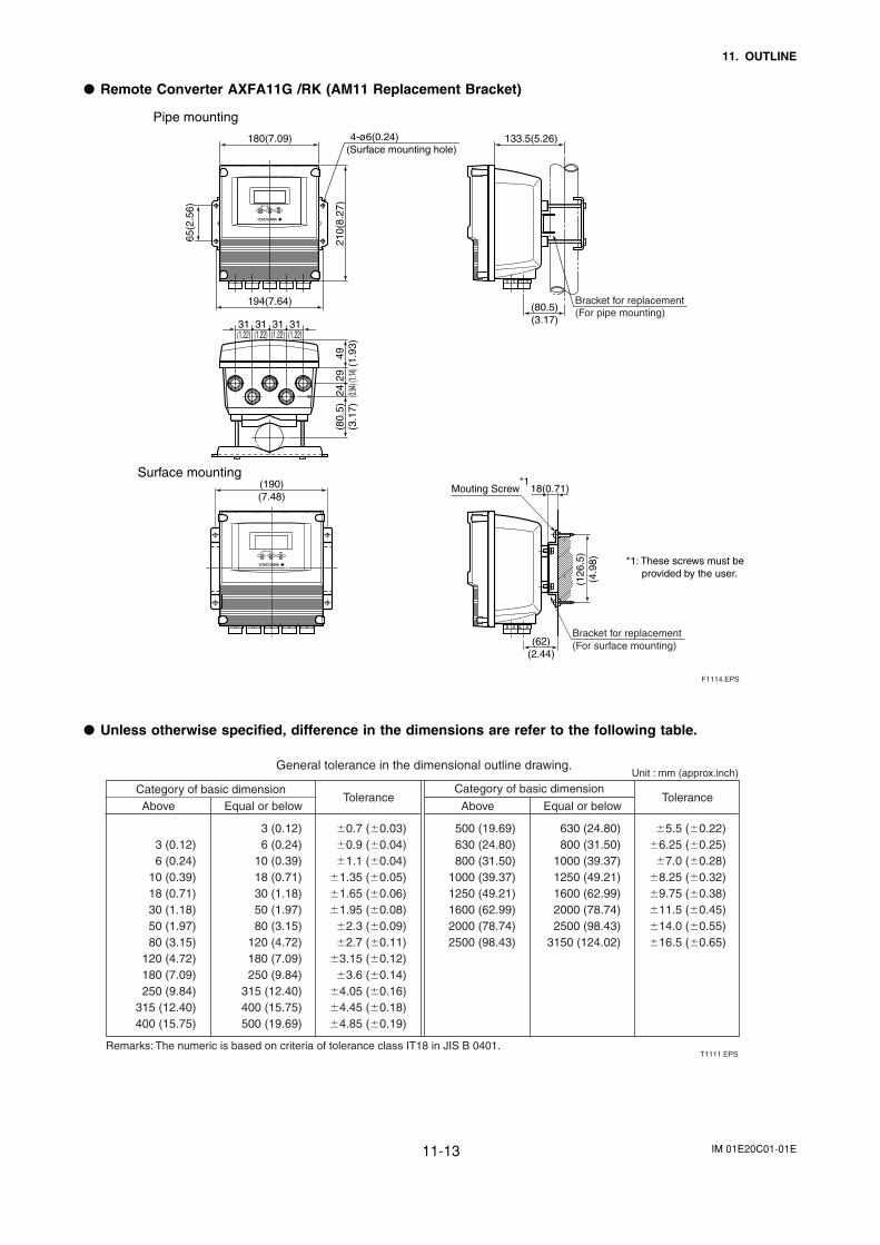
IM 01E20C01-01E11-13
11. OUTLINE
Remote Converter AXFA11G /RK (AM11 Replacement Bracket)
Pipe mounting
133.5(5.26)180(7.09)
194(7.64)
210(
8.27
)(8
0.5)
(3.1
7)49
(1.9
3)29 (1.
14)24 (0.
94)
65(2
.56)
(80.5)(3.17)31
(1.22)31(1.22)
31(1.22)
31(1.22)
F1114.EPS
Bracket for replacement(For pipe mounting)
4-ø6(0.24)(Surface mounting hole)
(190)(7.48)
Bracket for replacement(For surface mounting)(62)
(2.44)
18(0.71)Mouting Screw*1
Surface mounting
(126
.5)
(4.9
8) *1: These screws must be* provided by the user.
Unless otherwise specified, difference in the dimensions are refer to the following table.
Above Equal or below Above Equal or belowCategory of basic dimension Category of basic dimension
Tolerance Tolerance
3 (0.12)6 (0.24)
10 (0.39)18 (0.71)30 (1.18)50 (1.97)80 (3.15)
120 (4.72)180 (7.09)250 (9.84)
315 (12.40)400 (15.75)
3 (0.12)6 (0.24)
10 (0.39)18 (0.71)30 (1.18)50 (1.97)80 (3.15)
120 (4.72)180 (7.09)250 (9.84)
315 (12.40)400 (15.75)500 (19.69)
0.7 (0.03)0.9 (0.04)1.1 (0.04)
1.35 (0.05)1.65 (0.06)1.95 (0.08)
2.3 (0.09)2.7 (0.11)
3.15 (0.12)3.6 (0.14)
4.05 (0.16)4.45 (0.18)4.85 (0.19)
500 (19.69)630 (24.80)800 (31.50)
1000 (39.37)1250 (49.21)1600 (62.99)2000 (78.74)2500 (98.43)
630 (24.80)800 (31.50)
1000 (39.37)1250 (49.21)1600 (62.99)2000 (78.74)2500 (98.43)
3150 (124.02)
5.5 (0.22)6.25 (0.25)
7.0 (0.28)8.25 (0.32)9.75 (0.38)11.5 (0.45)14.0 (0.55)16.5 (0.65)
Remarks: The numeric is based on criteria of tolerance class IT18 in JIS B 0401.
General tolerance in the dimensional outline drawing.Unit : mm (approx.inch)
T1111.EPS
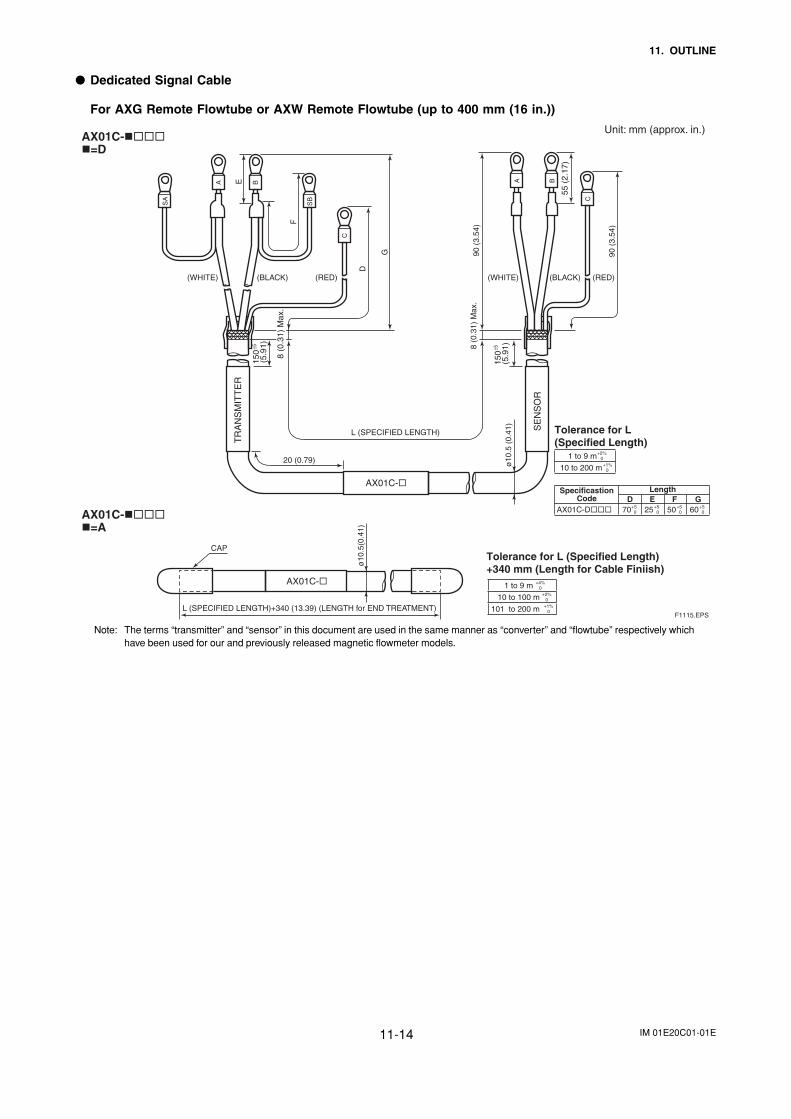
IM 01E20C01-01E11-14
11. OUTLINE
Dedicated Signal Cable
For AXG Remote Flowtube or AXW Remote Flowtube (up to 400 mm (16 in.))
Unit: mm (approx. in.)AX01C-
Tolerance for L(Specified Length)
Tolerance for L (Specified Length)+340 mm (Length for Cable Finiish)
1 to 9 m +2%0
10 to 200 m +1%0
AX01C-D 70 +50 25 +5
0 50 +50 60 +5
0
=D
20 (0.79)
TR
AN
SM
ITT
ER
SE
NS
OR
ø10
.5 (
0.41
)
AX01C-
L (SPECIFIED LENGTH)
150
(5.9
1)8 (0
.31)
Max
.
150
±5
(5.
91)
D
G 90 (
3.54
)
55 (
2.17
)
90 (
3.54
)F
E
SA
SB
A
C
B A
C
B
8 (0
.31)
Max
.
AX01C-=A
CAP
ø10
.5(0
.41)
AX01C-
L (SPECIFIED LENGTH)+340 (13.39) (LENGTH for END TREATMENT) F1115.EPS
(WHITE) (BLACK) (RED)(WHITE) (BLACK) (RED)
±5
1 to 9 m
10 to 100 m
101 to 200 m
LengthD E F G
+4%0
+2%0
+1%0
SpecificastionCode
Note: The terms “transmitter” and “sensor” in this document are used in the same manner as “converter” and “flowtube” respectively whichhave been used for our and previously released magnetic flowmeter models.
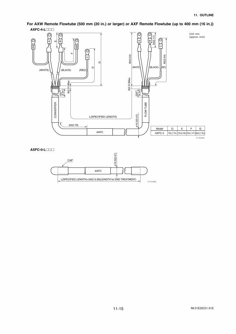
IM 01E20C01-01E11-15
11. OUTLINE
For AXW Remote Flowtube (500 mm (20 in.) or larger) or AXF Remote Flowtube (up to 400 mm (16 in.))AXFC-4-L
20(0.79)
CO
NV
ER
TE
R
FLO
W T
UB
E
ø10
.5(0
.41)
AXFC
L(SPECIFIED LENGTH)
150
5
(5.9
1)8(0.
31)M
ax.
150
5
(5.
91)
D
G 90(3
.54)
55(2
.17)
90(3
.54)
F
E
SA
SB
A
C
B A
C
B
8(0.
31)M
ax.
(WHITE) (BLACK) (RED)(WHITE) (BLACK) (RED)
Model
AXFC-4
D
70(2.76)
E
25(0.98)
F
50(1.97)
G
60(2.36)
Unit: mm(approx. inch)
F1116.EPS
AXFC-0-L
CAP
ø10
.5(0
.41)
AXFC
L(SPECIFIED LENGTH)+340(13.39)(LENGTH for END TREATMENT) F1117.EPS
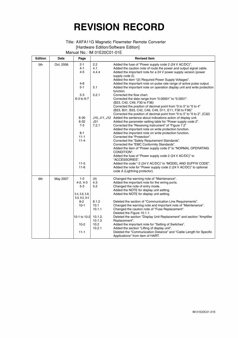
IM 01E20C01-01E
REVISION RECORDTitle: AXFA11G Magnetic Flowmeter Remote Converter
[Hardware Edition/Software Edition]Manual No.: IM 01E20C01-01E
2.2 Added the fuse of “Power supply code 2 (24 V AC/DC)”.4.1 Added the caution note of route the power and output signal cable.4.4.4 Added the important note for a 24 V power supply version (power
supply code 2).Added the item “(2) Required Power Supply Voltages”.Added the important note on pulse rate range of active pulse output.
5.1 Added the important note on operation display unit and write protection function.
5.2.1 Corrected the flow chart.Corrected the data range from “0.00001” to “0.0001”.(B23, C42, C49, F30 to F36)Corrected the position of decimal point from “0 to 5” to “0 to 4”(B23, B31, B33, C42, C46, C49, D11, E11, F30 to F36)”Corrected the position of decimal point from “0 to 5” to “0 to 2”. (C32)
J10, J11, J12 Added the sentence about indications action of display unit.J31 Added the parameter setting table for “Power supply code 2”.7.2.1 Corrected the “Receiving instrument” of “Figure 7.2”
Added the important note on write protection function.Added the important note on write protection function.Corrected the “Protection”.Corrected the “Safety Requirement Standards”.Corrected the “EMC Conformity Standards”.Added the item of “Power supply code 2” to “NORMAL OPERATING CONDITION”.Added the fuse of “Power supply code 2 (24 V AC/DC)” to “ACCESSORIES”.Added the code “-2 (24 V AC/DC)” to “MODEL AND SUFFIX CODE”.Added the note for “Power supply code 2 (24 V AC/DC)” to optional code A (Lightning protector).
(4) Changed the warning note of "Maintenance".4.3 Added the important note for the wiring ports.5.2 Changed the note of entry mode.
Added the NOTE for display unit setting.Added the NOTE for display unit setting.
8.1.2 Deleted the section of "Communication Line Requirements".10.1 Changed the warning note and important note of "Maintenance".10.1.1 Changed the caution note of "Fuse Replacement".
Deleted the Figure 10.1.1.10.1.2, Deleted the section "Display Unit Replacement" and section "Amplifier10.1.3 Replacement".10.2 Added the important note for "Setting of Switches".10.2.1 Added the section "Lifting of display unit".
Deleted the "Communication Distance" and "Cable Length for Specific Applications" from item of HART.
Edition Date Page Revised item
5th
6th
Oct. 2006
May 2007
2-14-14-5
4-85-1
5-36-3 to 6-7
6-306-327-3
8-111-111-4
11-511-6
1-24-2, 4-3
5-3
5-4, 5-6, 5-8,5-9, 9-2, 9-4
8-2 10-1
10-1 to 10-2
10-2
11-1
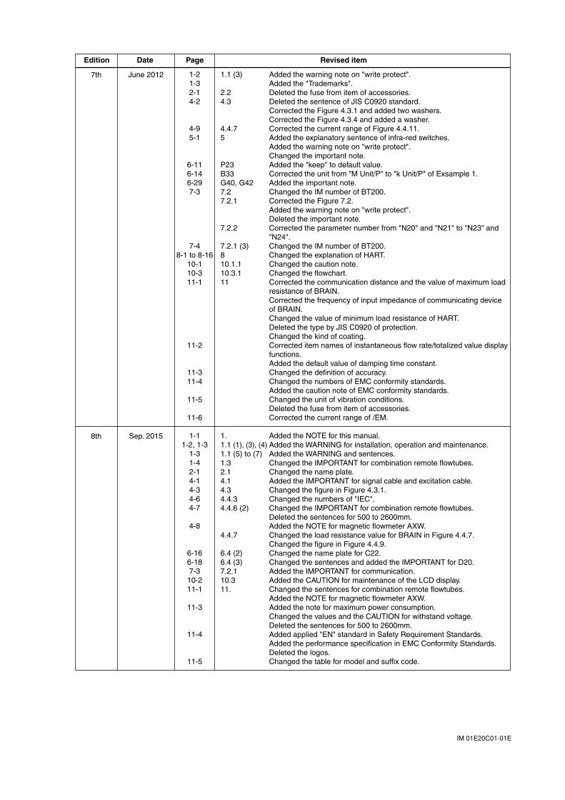
IM 01E20C01-01E
1.1 (3) Added the warning note on "write protect".Added the "Trademarks".
2.2 Deleted the fuse from item of accessories.4.3 Deleted the sentence of JIS C0920 standard.
Corrected the Figure 4.3.1 and added two washers.Corrected the Figure 4.3.4 and added a washer.
4.4.7 Corrected the current range of Figure 4.4.11.5 Added the explanatory sentence of infra-red switches.
Added the warning note on "write protect".Changed the important note.
P23 Added the "keep" to default value.B33 Corrected the unit from "M Unit/P" to "k Unit/P" of Exsample 1.G40, G42 Added the important note.7.2 Changed the IM number of BT200.7.2.1 Corrected the Figure 7.2.
Added the warning note on "write protect".Deleted the important note.
7.2.2 Corrected the parameter number from "N20" and "N21" to "N23" and "N24".
7.2.1 (3) Changed the IM number of BT200.8 Changed the explanation of HART.10.1.1 Changed the caution note.10.3.1 Changed the flowchart.11 Corrected the communication distance and the value of maximum load
resistance of BRAIN.Corrected the frequency of input impedance of communicating device of BRAIN. Changed the value of minimum load resistance of HART.Deleted the type by JIS C0920 of protection.Changed the kind of coating.Corrected item names of instantaneous flow rate/totalized value display functions.Added the default value of damping time constant.Changed the definition of accuracy.Changed the numbers of EMC conformity standards.Added the caution note of EMC conformity standards.Changed the unit of vibration conditions.Deleted the fuse from item of accessories.Corrected the current range of /EM.
1. Added the NOTE for this manual.1.1 (1), (3), (4) Added the WARNING for installation, operation and maintenance.1.1 (5) to (7) Added the WARNING and sentences.1.3 Changed the IMPORTANT for combination remote flowtubes.2.1 Changed the name plate.4.1 Added the IMPORTANT for signal cable and excitation cable.4.3 Changed the figure in Figure 4.3.1.4.4.3 Changed the numbers of "IEC".4.4.6 (2) Changed the IMPORTANT for combination remote flowtubes.
Deleted the sentences for 500 to 2600mm. Added the NOTE for magnetic flowmeter AXW.4.4.7 Changed the load resistance value for BRAIN in Figure 4.4.7. Changed the figure in Figure 4.4.9.6.4 (2) Changed the name plate for C22.6.4 (3) Changed the sentences and added the IMPORTANT for D20.7.2.1 Added the IMPORTANT for communication.10.3 Added the CAUTION for maintenance of the LCD display.11. Changed the sentences for combination remote flowtubes. Added the NOTE for magnetic flowmeter AXW. Added the note for maximum power consumption.
Changed the values and the CAUTION for withstand voltage. Deleted the sentences for 500 to 2600mm. Added applied "EN" standard in Safety Requirement Standards. Added the performance specification in EMC Conformity Standards. Deleted the logos. Changed the table for model and suffix code.
Edition Date Page Revised item
7th
8th
June 2012
Sep. 2015
1-21-32-14-2
4-95-1
6-116-146-297-3
7-48-1 to 8-16
10-110-311-1
11-2
11-311-4
11-5
11-6
1-11-2, 1-3
1-31-42-14-14-34-64-7
4-8
6-166-187-310-211-1
11-3
11-4
11-5
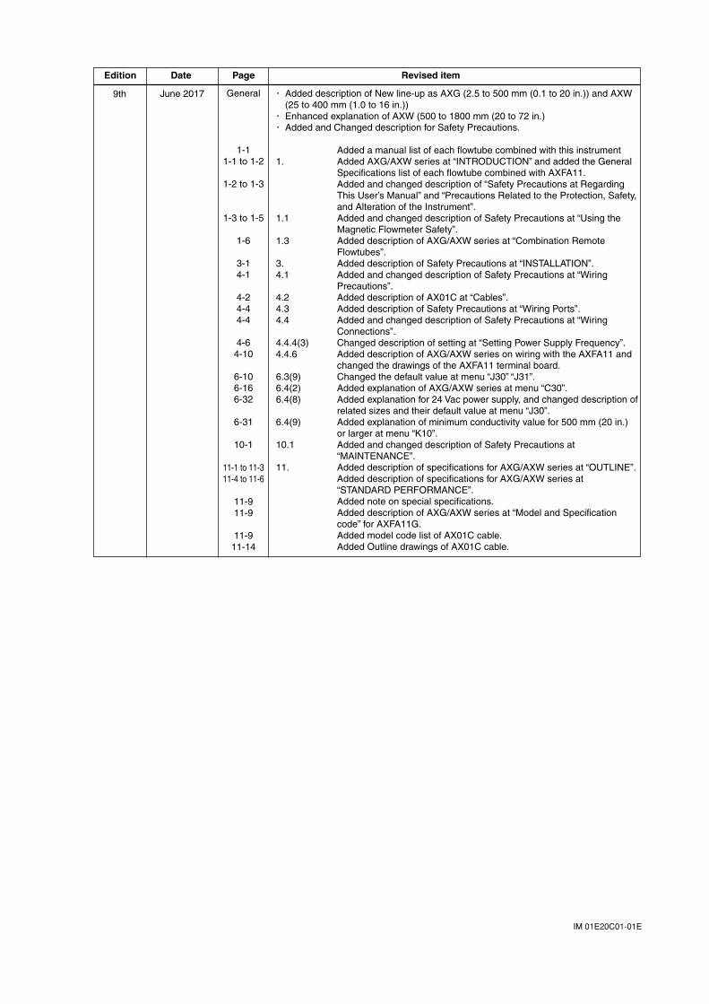
IM 01E20C01-01E
・ Added description of New line-up as AXG (2.5 to 500 mm (0.1 to 20 in.)) and AXW (25 to 400 mm (1.0 to 16 in.))
・ Enhanced explanation of AXW (500 to 1800 mm (20 to 72 in.)・ Added and Changed description for Safety Precautions.
Added a manual list of each flowtube combined with this instrument1. Added AXG/AXW series at “INTRODUCTION” and added the General
Specifications list of each flowtube combined with AXFA11.Added and changed description of “Safety Precautions at Regarding This User’s Manual” and “Precautions Related to the Protection, Safety, and Alteration of the Instrument”.
1.1 Added and changed description of Safety Precautions at “Using the Magnetic Flowmeter Safety”.
1.3 Added description of AXG/AXW series at “Combination Remote Flowtubes”.
3. Added description of Safety Precautions at “INSTALLATION”.4.1 Added and changed description of Safety Precautions at “Wiring
Precautions”.4.2 Added description of AX01C at “Cables”.4.3 Added description of Safety Precautions at “Wiring Ports”.4.4 Added and changed description of Safety Precautions at “Wiring
Connections”.4.4.4(3) Changed description of setting at “Setting Power Supply Frequency”.4.4.6 Added description of AXG/AXW series on wiring with the AXFA11 and
changed the drawings of the AXFA11 terminal board. 6.3(9) Changed the default value at menu “J30” “J31”.6.4(2) Added explanation of AXG/AXW series at menu “C30”.6.4(8) Added explanation for 24 Vac power supply, and changed description of
related sizes and their default value at menu “J30”. 6.4(9) Added explanation of minimum conductivity value for 500 mm (20 in.)
or larger at menu “K10”.10.1 Added and changed description of Safety Precautions at
“MAINTENANCE”.11. Added description of specifications for AXG/AXW series at “OUTLINE”.
Added description of specifications for AXG/AXW series at “STANDARD PERFORMANCE”.Added note on special specifications.Added description of AXG/AXW series at “Model and Specification code” for AXFA11G. Added model code list of AX01C cable.Added Outline drawings of AX01C cable.
Edition Date Page Revised item
9th June 2017 General
1-11-1 to 1-2
1-2 to 1-3
1-3 to 1-5
1-6
3-14-1
4-24-44-4
4-64-10
6-106-166-32
6-31
10-1
11-1 to 11-311-4 to 11-6
11-911-9
11-911-14
![User´s AXFA14G/C Manual Magnetic Flowmeter Remote ... · AXFA14G/C Magnetic Flowmeter Remote Converter [Hardware Edition/Software Edition] AXF Magnetic Flowmeter Integral Flowmeter](https://img.pdfslide.us/doc/110x75/5e9c29ae5a06915e2b2224e0/users-axfa14gc-manual-magnetic-flowmeter-remote-axfa14gc-magnetic-flowmeter.jpg)


![AXFA11G Magnetic Flowmeter Remote Converter [Hardware Edition/Software Edition… · 2021. 1. 24. · ADMAG TI Series AXW Magnetic Flowmeter [Size: 500 to 1800 mm (20 to 72 in.)]](https://img.pdfslide.us/doc/110x75/60c55d286bdb095bdc297a8e/axfa11g-magnetic-flowmeter-remote-converter-hardware-editionsoftware-2021-1.jpg)