Embed Size (px)
Citation preview

American AVK CompanyAn ISO 9001 registered companyCopyright © AVK Group A/S 2018
Maintenance Manual Series 34*Subject to change without notice. (rev.11/18 E)
AVK SERIES 34 WALL MOUNTED & TELESCOPICPOST INDICATORS, UL LISTED, FM APPROVED FIELD MAINTENANCE ANDINSTRUCTION MANUAL
TABLE OF CONTENTS
EXPLODED ASSEMBLY / PARTS LISTINTRODUCTION / DESCRIPTION
- MAINTENANCE - TOOL REQUIREMENTS - ADJUSTING TARGET SERIES 3400 - ADJUSTING TARGET SERIES 3480 - MOUNTING SERIES 3400 TO VALVE - ADJUSTING TO GROUND LEVEL - WALL POST SELECTION CHART - MOUNTING SERIES 3480 TO VALVE - INSTALLATION OF A SUPERVISORY SWITCH
AM
ER
ICA
N A
VK
CO
MP
AN
Y
* For Series 3400 Assemblies manufactured after 8/12, and
Series 3480 Assemblies manufactured after 6/17.

page 1
Am
erican AVK
Series 34 Indicator P
ostsE
xploded Parts B
reakdown
F301
F325
F302
F324
F303F326
F304
F305F315
F306
F312
F3F312
F308F3
F327F309
F306
F309
F328
F310F313
F314F315
See D
etail "A"
F332
F311F316
F333
F317F335
F334F316
F320
F320
F321
F323
F318
F322
F323
F319
F335F311
F308
F310
F336
F309
See D
etail "A"
Detail "A
"
Fig. 1
Series 3480
Wall P
ost Indicator
Series 3400
Telescopic Post Indicator
F216
F337
F337
F216
F314

page 2
Item No. Description MaterialF216 Bonnet Bolt Zinc Plate, 304, 316 Stainless steelF3 Window Screw 316 Stainless steelF301 Eyebolt Zinc Plated SteelF302 Eye Bolt Washer M16x50x3 Zinc Plated SteelF303 Handwheel (3480) Grey Iron, ASTM A126, “B”F304 Stem Nut - Series 3480 Copper AlloyF305 Wall Post Head Ductile Iron, ASTM A536F306 Window Acrylic (PMMA)F308 Flange Bolt Zinc Plate, 304, 316 Stainless steelF309 Flange Bolt Washer Zinc Plate, 304, 316 Stainless steelF310 Flange Bolt Nut Zinc Plate, 304, 316 Stainless steelF311 Wrench Nut Adapter Set Screw 304 Stainless steelF312 1/2” Pipe Plug Zinc Plated SteelF313 Wall Post Stem Mild SteelF314 Stem Nut O-ring NBRF315 Stem Nut Snap Ring 304 Stainless steelF316 Cotter Pin 431 Stainless steelF317 Wrench Nut Adapter (3480) Ductile Iron, ASTM A536F318 Target Copper AlloyF319 Shut Plate Painted AluminumF320 Plate Nut Zinc Plated SteelF321 Open Plate Painted AluminumF322 Plate Attachment Screw Zinc Plated SteelF323 Target Spacer Mild SteelF324 Upper Stem Attachment Pin (3400) 316 Stainless steelF325 Stem Nut - Series 3400 Copper AlloyF326 Operating Wrench Ductile Iron, ASTM A536F327 Telescopic Post Head/Upper Barrel Ductile Iron, ASTM A536F328 Telescopic Post Upper Stem Mild SteelF332 Lower Barrel PVC - DR14 UL ListedF333 Lower Stem Mild SteelF334 Wrench Nut Adapter (3400) Ductile Iron, ASTM A536F335 Telescopic Post Attachment Bolt Zinc Plate, 304, 316 Stainless steelF336 Bell Adapter Ductile Iron, ASTM A536F337 Bonnet Ductile Iron, ASTM A536

page 3
MAINTENANCE
INTRODUCTION / DESCRIPTION:
American AVK supplies two models of Indicator Posts for valve sizes 4" through 16". The model 3400, Telescopic Indicator Post, and the model 3480, Wall Post indicator. Both models are UL listed and FM approved. (Note: FM approval to 14" )
TOOL REQUIREMENTS:
INCH AND METRIC WRENCH / TOOL REQUIREMENTS FOR AMERICAN AVK POST INDICATORS
Description/Item Number Tool
Post Indicator Stem Nut (F304,F325) Stem Operating Wrench (3400)Target Plate Screws (F322) Flat blade screwdriverWrench Nut Adapter Cotter Pin(F316) Standard PliersStem Nut Snap Ring (F315) External Snap Ring Pliers1/2” Pipe Plug (F312) Adjustable WrenchTarget Plate Nuts (F320) 7/16” 11mmWindow Screw (Allen) (F3) 5/32” 4mmWrench Nut Adapter Set Screw (Allen) (F311) 15/64” 6mmFlange Bolts/Nuts (F308,F310) 15/16” 24mmAttachment/Adjustment Bolts (3400) (F329) 1-1/4” 30mmBonnet Bolts 3/8" 10mm

Fig. 2B
Fig. 2C
Open Left
Open Right
page 4
MAINTENANCE:
ADJUSTING THE TARGET (FOR SERIES 3400 TYPE INDICATORS):(For assemblies made after 8/12)NOTE:For an "open left" valve the "OPEN" sign should be mounted above the "SHUT" sign. (Fig. 2B) For an "open right" valve the "SHUT" sign should be mounted above the "OPEN" sign. (Fig. 2C).
1. With a 3/8”, (10mm) allen wrench, remove the four Bonnet Bolts (F216) attaching the Bonnet (F337), to the Head/Upper Barrel Assembly (F327). (See Fig. 2A).2. Pull the Bonnet and Target Assembly away from the Head/ Upper Barrel.3. If the Post Indicator is to be mounted on an open left valve, the "OPEN" Plate (F321) remains in the top position of the Target (F318). (See Fig. 2B).4. To configure for "open right" remove the Plate Attachment Screws (F322), and Plate Nuts (F320) with a flat bladed screwdriver and 7/16”,(11mm) wrench. Switch the locations of the “OPEN” and “SHUT” Plates. The “SHUT” Plate F319, should be mounted on top. (See Fig. 2C).5. Re-attach the associated hardware. Ensure that the “OPEN” Plate is in the correct location for the size of valve that the Post Indicator is being mounted on.
NOTE: Each set of dimples in the target is marked for the correct valve size (4" through (12-16")). The Target Spacer (F323) should always be mounted on the Attachment Bolts that attach the “OPEN” plate. (See Fig. 3, on page 5)
6. Lift the re-assembled post indicator Bonnet/Target Assembly onto the Head/Upper Barrel Assembly. Make sure the upper stem rod slides into the lower stem rod.7. Install and tighten the four Bonnet Bolts (F216) attaching the Bonnet (F337) to the Head/Upper Barrel Upper Barrel Assembly (F327) .
Fig. 2A
F216
F328
F327
Counter-clockwise to remove. (Shown)Clockwise to re-engage
F319
F318
F321
F320
F322F323

page 5
MAINTENANCE
ADJUSTING THE TARGET (FOR SERIES 3480 TYPE INDICATORS):
NOTE: For an "open left" valve the "OPEN" sign should be mounted above the "SHUT" sign. (Fig. 2B) For an "open right" valve the "SHUT" sign should be mounted above the "OPEN" sign. (Fig. 2C) In September 2010, American AVK switched series 34 post indicators from a preset 4-inch valve to a preset 6-inch valve. Refer to "ADJUSTING THE TARGET (FOR SERIES 3400 TYPE INDICATORS):"
1. Remove the four sets of Attachment Bolts/Washers/Nuts (F308, F309, F310) using a 15/16” (24mm) wrench. (See Fig. 1)2. Lift the Post Indicator Head (F305) off of the Wall Post Stem (F313).3. If present, turn the Handwheel (F303) counter-clock-wise to remove the Target (F318). If the Post Indicator does not have a Handwheel, use an adjustable wrench or Operating Wrench (F326) on the Stem Nut (F304) to remove the Target.4. If the Post Indicator is to be mounted on an open left valve, the "OPEN" Plate (F321) remains in the top position of the Target (F318). 5. To configure for "open right" remove the Plate Attachment Screws (F322), and Plate Nuts (F320) with a flat bladed screwdriver and 7/16”,(11mm) wrench. Switch the locations of the “OPEN” and “SHUT” Plates. The “SHUT” Plate should be mounted on top.6. To re-engage the Target, turn the Handwheel or wrench clock-wise to thread the Target onto the Stem Nut. Continue to thread the Target onto the Stem Nut until the appropriate position Plate is centered in the Window (F306). The “OPEN” or “SHUT” should match the position of the valve. Insure that the valve is either fully open or fully closed. ( See Section “MOUNTING THE TELESCOPING POST INDICATOR (SERIES 3400) ONTO A VALVE” ) on page 6.7. Gently align and slide the assembled Post Indicator Head onto the Wall Post Stem.8. Align the four bolt holes with the Post Indicator Plate on the valve and install the Attachment Hardware.
Fig. 3
4" Position6" Position8" Position10" Position12" through 16" Position*
* For 14"-16" valves, the 12" position is used and a a Stem Nut/ Target assembly with finer threads is used.
F318
F321
F320
F322
F323
F319
page 6
MAINTENANCE
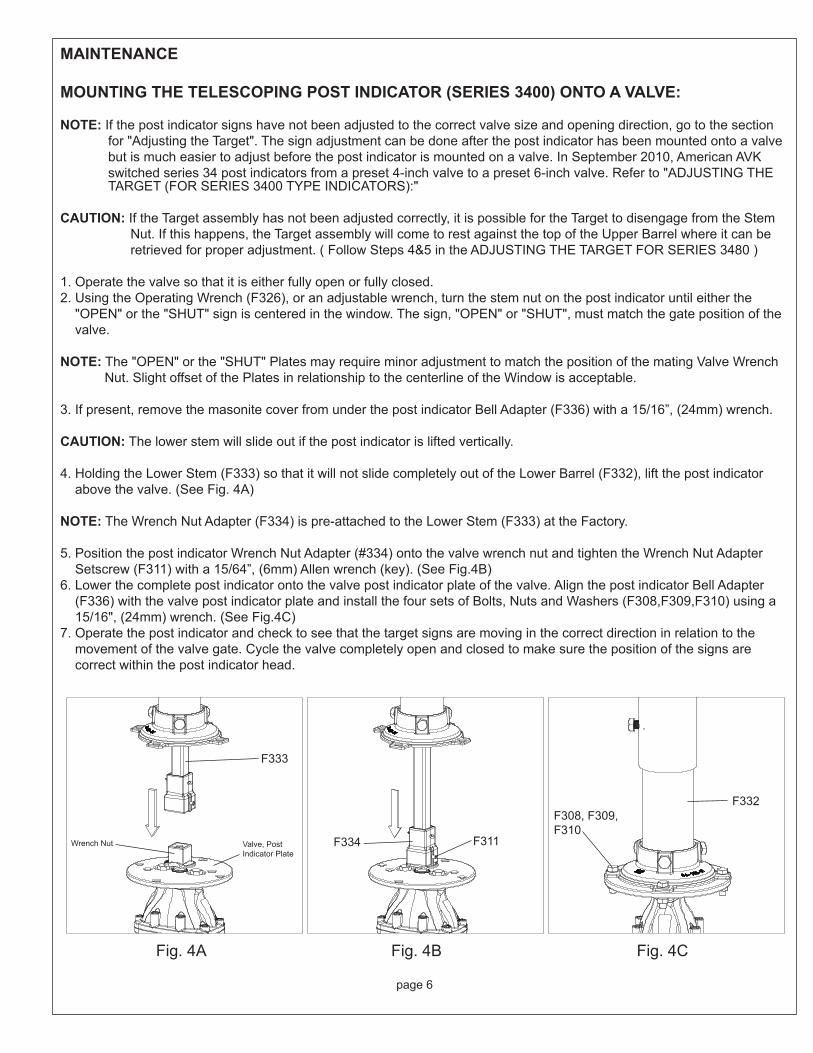
MOUNTING THE TELESCOPING POST INDICATOR (SERIES 3400) ONTO A VALVE:
NOTE: If the post indicator signs have not been adjusted to the correct valve size and opening direction, go to the section for "Adjusting the Target". The sign adjustment can be done after the post indicator has been mounted onto a valve but is much easier to adjust before the post indicator is mounted on a valve. In September 2010, American AVK switched series 34 post indicators from a preset 4-inch valve to a preset 6-inch valve. Refer to "ADJUSTING THE TARGET (FOR SERIES 3400 TYPE INDICATORS):"
CAUTION: If the Target assembly has not been adjusted correctly, it is possible for the Target to disengage from the Stem Nut. If this happens, the Target assembly will come to rest against the top of the Upper Barrel where it can be retrieved for proper adjustment. ( Follow Steps 4&5 in the ADJUSTING THE TARGET FOR SERIES 3480 )
1. Operate the valve so that it is either fully open or fully closed.2. Using the Operating Wrench (F326), or an adjustable wrench, turn the stem nut on the post indicator until either the "OPEN" or the "SHUT" sign is centered in the window. The sign, "OPEN" or "SHUT", must match the gate position of the valve.
NOTE: The "OPEN" or the "SHUT" Plates may require minor adjustment to match the position of the mating Valve Wrench Nut. Slight offset of the Plates in relationship to the centerline of the Window is acceptable.
3. If present, remove the masonite cover from under the post indicator Bell Adapter (F336) with a 15/16”, (24mm) wrench.
CAUTION: The lower stem will slide out if the post indicator is lifted vertically.
4. Holding the Lower Stem (F333) so that it will not slide completely out of the Lower Barrel (F332), lift the post indicator above the valve. (See Fig. 4A)
NOTE: The Wrench Nut Adapter (F334) is pre-attached to the Lower Stem (F333) at the Factory.
5. Position the post indicator Wrench Nut Adapter (#334) onto the valve wrench nut and tighten the Wrench Nut Adapter Setscrew (F311) with a 15/64”, (6mm) Allen wrench (key). (See Fig.4B)6. Lower the complete post indicator onto the valve post indicator plate of the valve. Align the post indicator Bell Adapter (F336) with the valve post indicator plate and install the four sets of Bolts, Nuts and Washers (F308,F309,F310) using a 15/16", (24mm) wrench. (See Fig.4C)7. Operate the post indicator and check to see that the target signs are moving in the correct direction in relation to the movement of the valve gate. Cycle the valve completely open and closed to make sure the position of the signs are correct within the post indicator head.
Fig. 4B Fig. 4CFig. 4A
F333
Valve, Post Indicator Plate
Wrench Nut F334 F311
F308, F309,F310
F332

H1+H2+Bury
H1
H2
L
page 7
ADJUSTING THE POST INDICATOR TO THE GROUND LEVEL
NOTE: All AVK post indicators will telescope 22 ¼" (565mm) from the shortest to the longest length.
1. If you are adjusting the post indicator to the ground level after the post indicator has been installed onto a valve (standing vertically) then you must support the head assembly before proceeding to step 2.2. Loosen the two Attachment Bolts (F335) positioned at the bottom-side of the upper barrel. (See Fig.5)3. Lift or lower the upper barrel until the black stripe is at the ground level. The black stripe on the Upper Barrel is located approximately 30" (765mm) below the center of the sign window.4. Tighten the two bolts on the bottom-side of the upper barrel. (See Fig.5)
Fig. 5
Valve Size H1 (Inches/mm)
4" 13"/330mm6" 18"/455mm8" 22.5"/575mm
10" 27"/685mm12" 31"/785mm
14"-16" 41"/1041mm
Part Number
Length“L” ±4.0
H2
Inch MMInch
min. max.MM
min. max.34-150-61-00-X 42.1 1070.0 20.0" 43.0" 505.0 1090.034-150-61-01-X 64.2 1630.0 42.0" 65.0" 1065.0 1660.034-150-61-02-X 86.2 2190.0 64.0" 87.0" 1625.0 2210.0
F335

19"
14.17
page 8
A
B
C = wall thickness
WALL POST INDICATOR INSTALLATION CHARTSERIES 3480
Combine A+B+C to determine which length of Wall Post Stem to order. The length of the Wall Post Stem must be equal to or greater than the sum of A+B+C. If greater than, trim the stem to fall between the dimensions in “Detail A”
“A” = Length of Wall Post Stem. Fromoutside of wall to end of Stem.Minimum length of “A” 9.8”- 249mmMaximum length of “A” 13.5”- 343mm
Detail A
“B” = Distance from top of mountedValve Wrench Nut to inside of wall.
** For direct to valve mounting.
Wall Post Stem LengthsInch MM
34-150-88-00 9.8 250 **34-150-88-01 29.5 75034-150-88-02 49.2 1250
Minimum of 4” diameter clearancehole through wall.
4, 3/4” clearance holes drilledon 10.5” pitch diameter.

page 9
MOUNTING THE WALL POST INDICATOR (SERIES 3480) ONTO AN INSTALLED VALVE
NOTE: If the post indicator signs have not been adjusted to the correct valve size and opening direction, go to the section for "ADJUSTING THE TARGET". The sign adjustment can be done after the post indicator has been mounted onto a valve but is much easier to adjust before the post indicator is mounted on a valve. In September 2010, American AVK switched series 34 post indicators from a preset 4-inch valve to a preset 6-inch valve. Refer to "ADJUSTING THE TARGET (FOR SERIES 3400 TYPE INDICATORS): "CAUTION: If the Target assembly has not been adjusted correctly, it is possible for the Target to disengage from the Stem Nut. If this happens, the Target assembly can be retrieved for proper adjustment. ( Follow Step 5 in the "ADJUSTING THE TARGET FOR SERIES 3480")
1. Operate the valve so that it is either fully open or fully closed.2. Using the Operating Wrench (F326), or an adjustable wrench, or the Handwheel (F303) turn the stem nut on the post indicator until either the "OPEN" or the "SHUT" sign is centered in the window. The sign, "OPEN" or "SHUT", must match the gate position of the valve.
NOTE: The "OPEN" or the "SHUT" Plates may require minor adjustment to match the position of the mating Valve Wrench Nut. Slight offset of the Plates in relationship to the centerline of the Window is acceptable.
3. Remove the masonite cover from under the Wall Post Indicator Head (F305) with a 15/16”, (24mm) wrench.
NOTE: The Wall Post Stem (F313) and Wrench Nut Adapter (F317) are pre-assembled at the factory. Locktite has been applied to the threads of the Wrench Nut Set Screw (F311) to prevent loss during shipment.
4. A minimum 4” diameter access hole is required to install the Wall Post Stem Assembly. Insert the Stem Assembly through the wall and align the Wrench Nut Adapter (F317) with the Valve Wrench Nut. Slide the adapter over the valve wrench nut until it stops against the bottom flange of the wrench nut. Tighten the Set Screw (F311) to secure the adapter. (See Wall Post Installation Chart Series 3480)5. Measure and cut if necessary, the end of the Wall Post Stem according to dimensions in “Detail A” of the Wall Post Installation Chart.
NOTE: The Wall Post Head has four, 3/4” mounting holes on a 10.5” pitch diameter. Mating mounting hardware should be installed prior to Step 6.
6. Using a sufficient supporting device, lift Wall Post Head Assembly and align the internal Stem Nut square relief with the Wall Post Stem. Minor adjustment of the Handwheel may be necessary to position the square relief correctly. (See Fig. 6)7. Slide the Wall Post Head up to the wall and mount with appropriate hardware.8. Operate the post indicator and check to see that the target signs are moving in the correct direction in relation to the movement of the valve gate. Cycle the valve completely open and closed to make sure the position of the signs are correct within the post indicator head.
Fig. 6
Square relief
Wall PostStem
page 10
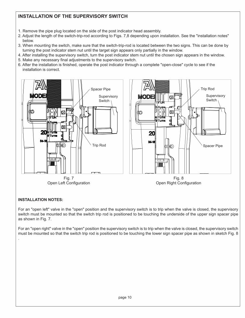
INSTALLATION OF THE SUPERVISORY SWITCH
1. Remove the pipe plug located on the side of the post indicator head assembly.2. Adjust the length of the switch-trip-rod according to Figs. 7,8 depending upon installation. See the "installation notes" below.3. When mounting the switch, make sure that the switch-trip-rod is located between the two signs. This can be done by turning the post indicator stem nut until the target sign appears only partially in the window.4. After installing the supervisory switch, turn the post indicator stem nut until the chosen sign appears in the window.5. Make any necessary final adjustments to the supervisory switch.6. After the installation is finished, operate the post indicator through a complete "open-close" cycle to see if the installation is correct.
INSTALLATION NOTES:
For an "open left" valve in the "open" position and the supervisory switch is to trip when the valve is closed, the supervisory switch must be mounted so that the switch trip rod is positioned to be touching the underside of the upper sign spacer pipe as shown in Fig. 7.
For an "open right" valve in the "open" position the supervisory switch is to trip when the valve is closed, the supervisory switch must be mounted so that the switch trip rod is positioned to be touching the lower sign spacer pipe as shown in sketch Fig. 8 .
Spacer Pipe
Spacer PipeTrip Rod
SupervisorySwitch
SupervisorySwitch
Trip Rod
Fig. 7Open Left Configuration
Fig. 8Open Right Configuration