Embed Size (px)
Citation preview
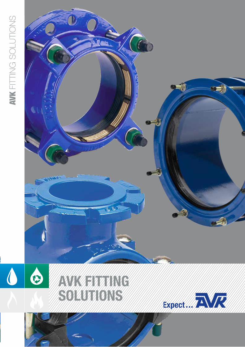
AVK
FITT
ING
SO
LUTI
ON
S
AVK FITTING SOLUTIONS
2 | AVK FITTING SOLUTIONS
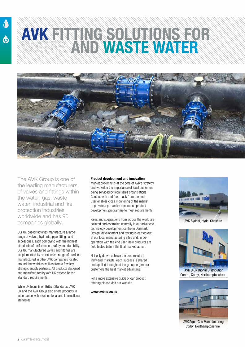
The AVK Group is one of the leading manufacturers of valves and fittings within the water, gas, waste water, industrial and fire protection industries worldwide and has 90 companies globally. Our UK based factories manufacture a large range of valves, hydrants, pipe fittings and accessories, each complying with the highest standards of performance, safety and durability. Our UK manufactured valves and fittings are supplemented by an extensive range of products manufactured in other AVK companies located around the world as well as from a few key strategic supply partners. All products designed and manufactured by AVK UK exceed British Standard requirements.
While UK focus is on British Standards, AVK UK and the AVK Group also offers products in accordance with most national and international standards.
Product development and innovationMarket proximity is at the core of AVK’s strategy and we value the importance of local customers being serviced by local sales organisations. Contact with and feed-back from the end-user enables close monitoring of the market to provide a pro-active continuous product development programme to meet requirements.
Ideas and suggestions from across the world are collated and controlled centrally in our advanced technology development centre in Denmark. Design, development and testing is carried out at our local manufacturing sites and, in co-operation with the end user, new products are field tested before the final market launch.
Not only do we achieve the best results in individual markets, each success is shared and applied throughout the group to give our customers the best market advantage.
For a more extensive guide of our product offering please visit our website
www.avkuk.co.uk
AVK FITTING SOLUTIONS FOR WATER AND WASTE WATER
AVK Syddal, Hyde, Cheshire
AVK UK National Distribution Centre, Corby, Northamptonshire
AVK Aqua-Gas Manufacturing, Corby, Northamptonshire
AVK FITTING SOLUTIONS | 3
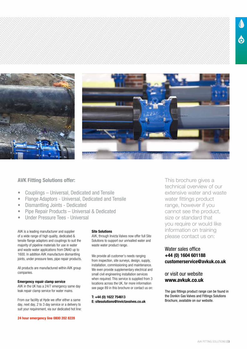
AVK is a leading manufacturer and supplier of a wide range of high quality, dedicated & tensile flange adaptors and couplings to suit the majority of pipeline materials for use in water and waste water applications from DN40 up to 1600. In addition AVK manufacture dismantling joints, under pressure tees, pipe repair products.
All products are manufactured within AVK group companies.
Emergency repair clamp service AVK in the UK has a 24/7 emergency same day leak repair clamp service for water mains.
From our facility at Hyde we offer either a same day, next day, 2 to 3 day service or a delivery to suit your requirement, via our dedicated hot line:
24 hour emergency line 0800 202 8228
Site SolutionsAVK, through Invicta Valves now offer full Site Solutions to support our unrivalled water and waste water product range.
We provide all customer’s needs ranging from inspection, site surveys, design, supply, installation, commissioning and maintenance. We even provide supplementary electrical and small civil engineering installation services when required. This service is supplied from 3 locations across the UK, for more information see page 89 in this brochure or contact us on:
T: +44 (0) 1622 754613E: [email protected]
This brochure gives a technical overview of our extensive water and waste water fittings product range, however if you cannot see the product, size or standard that you require or would like information on training please contact us on:
Water sales office +44 (0) 1604 [email protected]
or visit our websitewww.avkuk.co.uk
The gas fittings product range can be found in the Donkin Gas Valves and Fittings Solutions Brochure, available on our website.
AVK Fitting Solutions offer:
• Couplings – Universal, Dedicated and Tensile• Flange Adaptors - Universal, Dedicated and Tensile• Dismantling Joints - Dedicated• Pipe Repair Products – Universal & Dedicated • Under Pressure Tees - Universal
4 | AVK FITTING SOLUTIONS
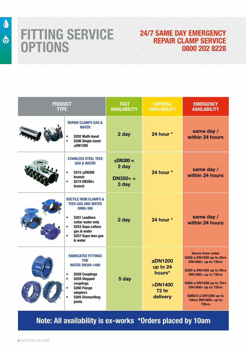
FITTING SERVICE OPTIONS
24/7 SAME DAY EMERGENCY REPAIR CLAMP SERVICE
0800 202 8228
PRODUCT TYPE
FAST AVAILABILITY
EXPRESS AVAILABILITY
EMERGENCY AVAILABILITY
REPAIR CLAMPS GAS & WATER
• S202 Multi-band• S206 Single-band
≤DN1200
2 day 24 hour *same day /
within 24 hours
STAINLESS STEEL TEES GAS & WATER
• S215 ≤DN300branch
• S215 DN350+branch
≤DN300 = 2 day
DN350+ = 3 day
24 hour *same day /
within 24 hours
DUCTILE IRON CLAMPS & TEES GAS AND WATER
DN80-300
• S201 Leadlesscollar water only
• S253 Supa collarsgas & water
• S257 Supa tees gas& water
2 day 24 hour *same day /
within 24 hours
FABRICATED FITTINGS FOR
WATER DN350-1400
• S258 Couplings• S259 Stepped
couplings• S260 Flange
adaptors• S265 Dismantling
joints
5 day
≤DN1200 up to 24hours*
>DN140072 hr
delivery
Hours from orderS258 ≤ DN1200 up to 5hrs
DN1400+ up to 72hrs
S259 ≤ DN1200 up to 5hrs DN1400+ up to 72hrs
S260 ≤ DN1200 up to 7hrs DN1400+ up to 72hrs
S265/3 ≤ DN1200 up to 10hrs DN1400+ up to
72hrs
Note: All availability is ex-works *Orders placed by 10am
AVK FITTING SOLUTIONS | 5
INDEXCO
UPLI
NGS
AND
ADAP
TORS
PAGE
REPA
IR C
LAM
PSAN
D TE
ESW
ALL
STAR
TERS
AN
D EN
D CA
PS
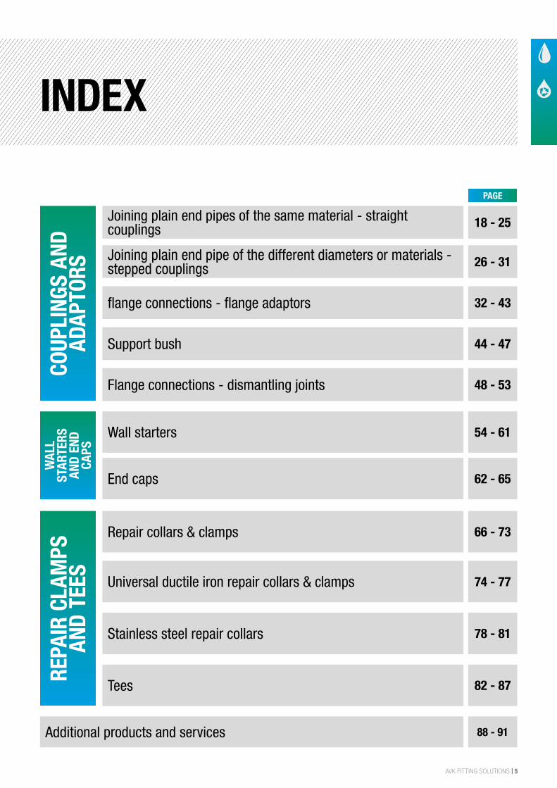
Joining plain end pipes of the same material - straight couplings 18 - 25
26 - 31
32 - 43
44 - 47
48 - 53
54 - 61
62 - 65
66 - 73
74 - 77
78 - 81
82 - 87
88 - 91
Repair collars & clamps
Joining plain end pipe of the different diameters or materials - stepped couplings
Universal ductile iron repair collars & clamps
flange connections - flange adaptors
Stainless steel repair collars
Wall starters
Support bush
Flange connections - dismantling joints
Tees
Additional products and services
End caps
6 | AVK FITTING SOLUTIONS
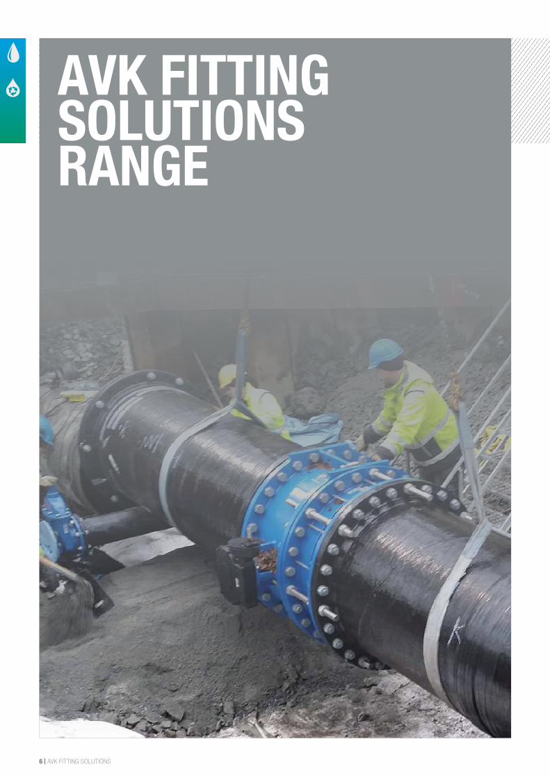
AVK FITTING SOLUTIONS RANGE
AVK FITTING SOLUTIONS | 7
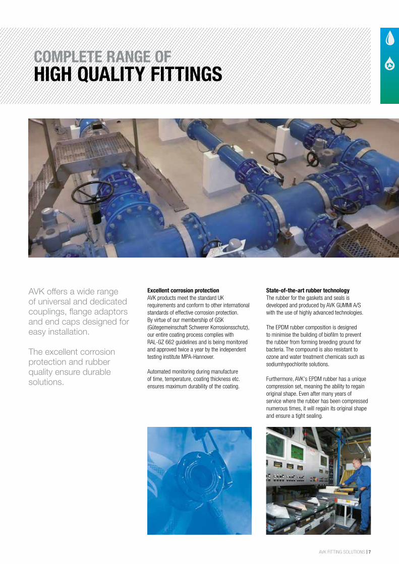
AVK offers a wide range of universal and dedicated couplings, flange adaptors and end caps designed for easy installation.
The excellent corrosion protection and rubber quality ensure durable solutions.
Excellent corrosion protectionAVK products meet the standard UK requirements and conform to other international standards of effective corrosion protection. By virtue of our membership of GSK (Gütegemeinschaft Schwerer Korrosionsschutz), our entire coating process complies with RAL-GZ 662 guidelines and is being monitored and approved twice a year by the independent testing institute MPA-Hannover.
Automated monitoring during manufacture of time, temperature, coating thickness etc. ensures maximum durability of the coating.
State-of-the-art rubber technology The rubber for the gaskets and seals is developed and produced by AVK GUMMI A/S with the use of highly advanced technologies.
The EPDM rubber composition is designed to minimise the building of biofilm to prevent the rubber from forming breeding ground for bacteria. The compound is also resistant to ozone and water treatment chemicals such as sodiumhypochlorite solutions.
Furthermore, AVK’s EPDM rubber has a unique compression set, meaning the ability to regain original shape. Even after many years of service where the rubber has been compressed numerous times, it will regain its original shape and ensure a tight sealing.
COMPLETE RANGE OFHIGH QUALITY FITTINGS
8 | AVK FITTING SOLUTIONS
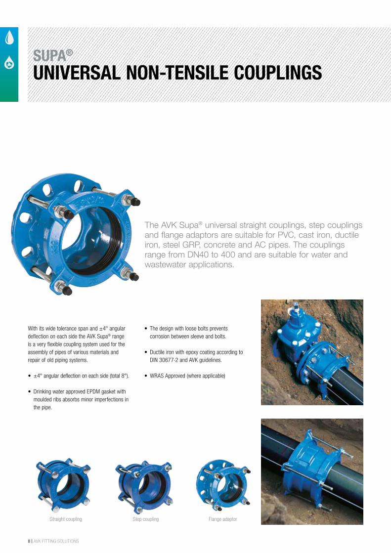
Flange adaptorStraight coupling Step coupling
With its wide tolerance span and ±4° angular deflection on each side the AVK Supa® range is a very flexible coupling system used for the assembly of pipes of various materials and repair of old piping systems.
• ±4° angular deflection on each side (total 8°).
• Drinking water approved EPDM gasket with moulded ribs absorbs minor imperfections in the pipe.
• The design with loose bolts prevents corrosion between sleeve and bolts.
• Ductile iron with epoxy coating according to DIN 30677-2 and AVK guidelines.
• WRAS Approved (where applicable)
The AVK Supa® universal straight couplings, step couplings and flange adaptors are suitable for PVC, cast iron, ductile iron, steel GRP, concrete and AC pipes. The couplings range from DN40 to 400 and are suitable for water and wastewater applications.
SUPA®
UNIVERSAL NON-TENSILE COUPLINGS
AVK FITTING SOLUTIONS | 9
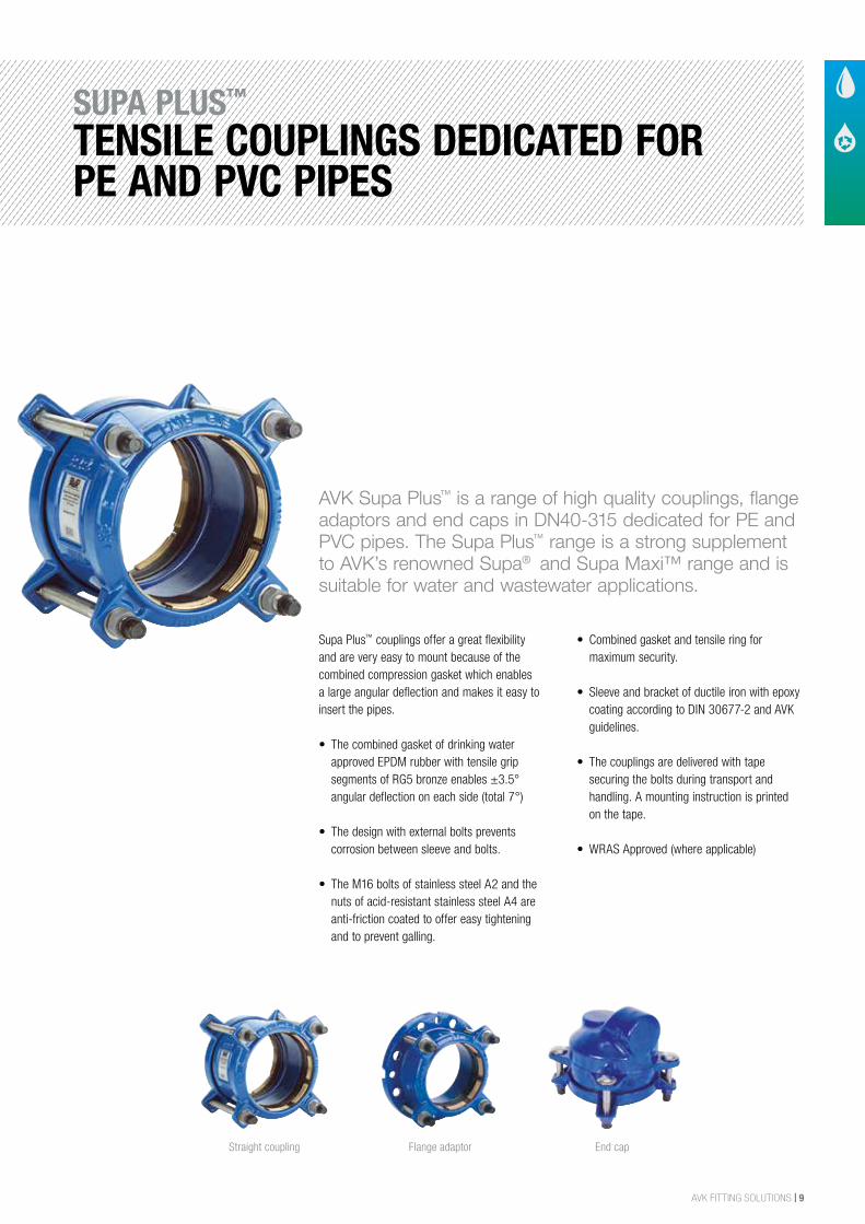
Supa Plus™ couplings offer a great flexibility and are very easy to mount because of the combined compression gasket which enables a large angular deflection and makes it easy to insert the pipes.
• The combined gasket of drinking water approved EPDM rubber with tensile grip segments of RG5 bronze enables ±3.5° angular deflection on each side (total 7°)
• The design with external bolts prevents corrosion between sleeve and bolts.
• The M16 bolts of stainless steel A2 and the nuts of acid-resistant stainless steel A4 are anti-friction coated to offer easy tightening and to prevent galling.
• Combined gasket and tensile ring for maximum security.
• Sleeve and bracket of ductile iron with epoxy coating according to DIN 30677-2 and AVK guidelines.
• The couplings are delivered with tape securing the bolts during transport and handling. A mounting instruction is printed on the tape.
• WRAS Approved (where applicable)
AVK Supa Plus™ is a range of high quality couplings, flange adaptors and end caps in DN40-315 dedicated for PE and PVC pipes. The Supa Plus™ range is a strong supplement to AVK’s renowned Supa® and Supa Maxi™ range and is suitable for water and wastewater applications.
End capStraight coupling Flange adaptor
SUPA PLUS™
TENSILE COUPLINGS DEDICATED FOR PE AND PVC PIPES
10 | AVK FITTING SOLUTIONS
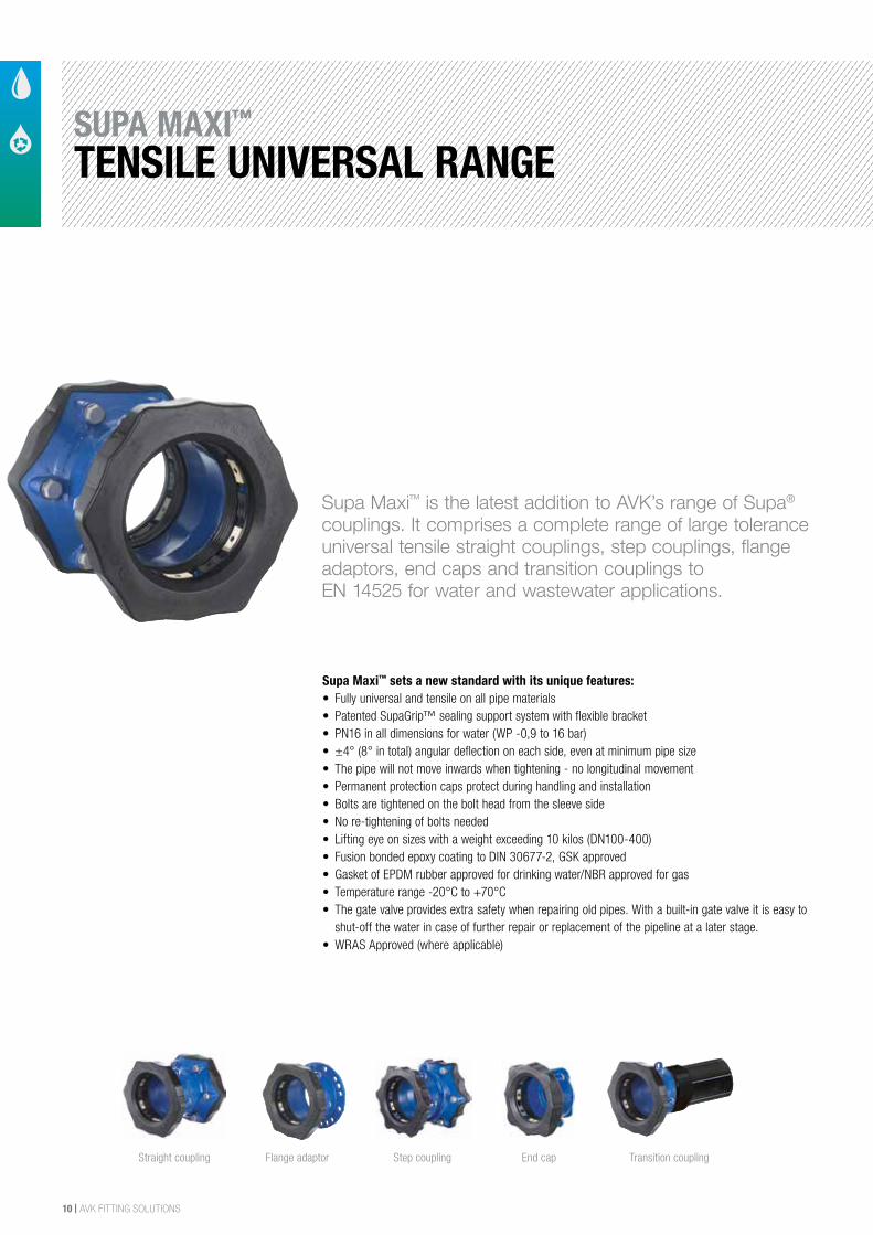
Supa Maxi™ sets a new standard with its unique features:• Fully universal and tensile on all pipe materials• Patented SupaGrip™ sealing support system with flexible bracket• PN16 in all dimensions for water (WP -0,9 to 16 bar)• ±4° (8° in total) angular deflection on each side, even at minimum pipe size• The pipe will not move inwards when tightening - no longitudinal movement• Permanent protection caps protect during handling and installation• Bolts are tightened on the bolt head from the sleeve side • No re-tightening of bolts needed• Lifting eye on sizes with a weight exceeding 10 kilos (DN100-400)• Fusion bonded epoxy coating to DIN 30677-2, GSK approved• Gasket of EPDM rubber approved for drinking water/NBR approved for gas• Temperature range -20°C to +70°C• The gate valve provides extra safety when repairing old pipes. With a built-in gate valve it is easy to
shut-off the water in case of further repair or replacement of the pipeline at a later stage.• WRAS Approved (where applicable)
Supa Maxi™ is the latest addition to AVK’s range of Supa® couplings. It comprises a complete range of large tolerance universal tensile straight couplings, step couplings, flange adaptors, end caps and transition couplings to EN 14525 for water and wastewater applications.
Step couplingStraight coupling Flange adaptor End cap Transition coupling
SUPA MAXI™
TENSILE UNIVERSAL RANGE
AVK FITTING SOLUTIONS | 11
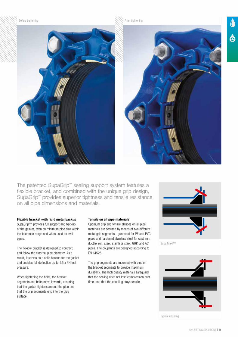
Minimum pipe sizeThe patented SupaGrip™ sealing support system features a flexible bracket, and combined with the unique grip design, SupaGrip™ provides superior tightness and tensile resistance on all pipe dimensions and materials.
Flexible bracket with rigid metal backupSupaGrip™ provides full support and backup of the gasket, even on minimum pipe size within the tolerance range and when used on oval pipes.
The flexible bracket is designed to contract and follow the external pipe diameter. As a result, it serves as a solid backup for the gasket and enables full deflection up to 1.5 x PN test pressure.
When tightening the bolts, the bracket segments and bolts move inwards, ensuring that the gasket tightens around the pipe and that the grip segments grip into the pipe surface.
Tensile on all pipe materials Optimum grip and tensile abilities on all pipe materials are secured by means of two different metal grip segments - gunmetal for PE and PVC pipes and hardened stainless steel for cast iron, ductile iron, steel, stainless steel, GRP, and AC pipes. The couplings are designed according to EN 14525.
The grip segments are mounted with pins on the bracket segments to provide maximum durability. The high quality materials safeguard that the sealing does not lose compression over time, and that the coupling stays tensile.
Before tightening After tightening
Supa Maxi™
Typical coupling
12 | AVK FITTING SOLUTIONS
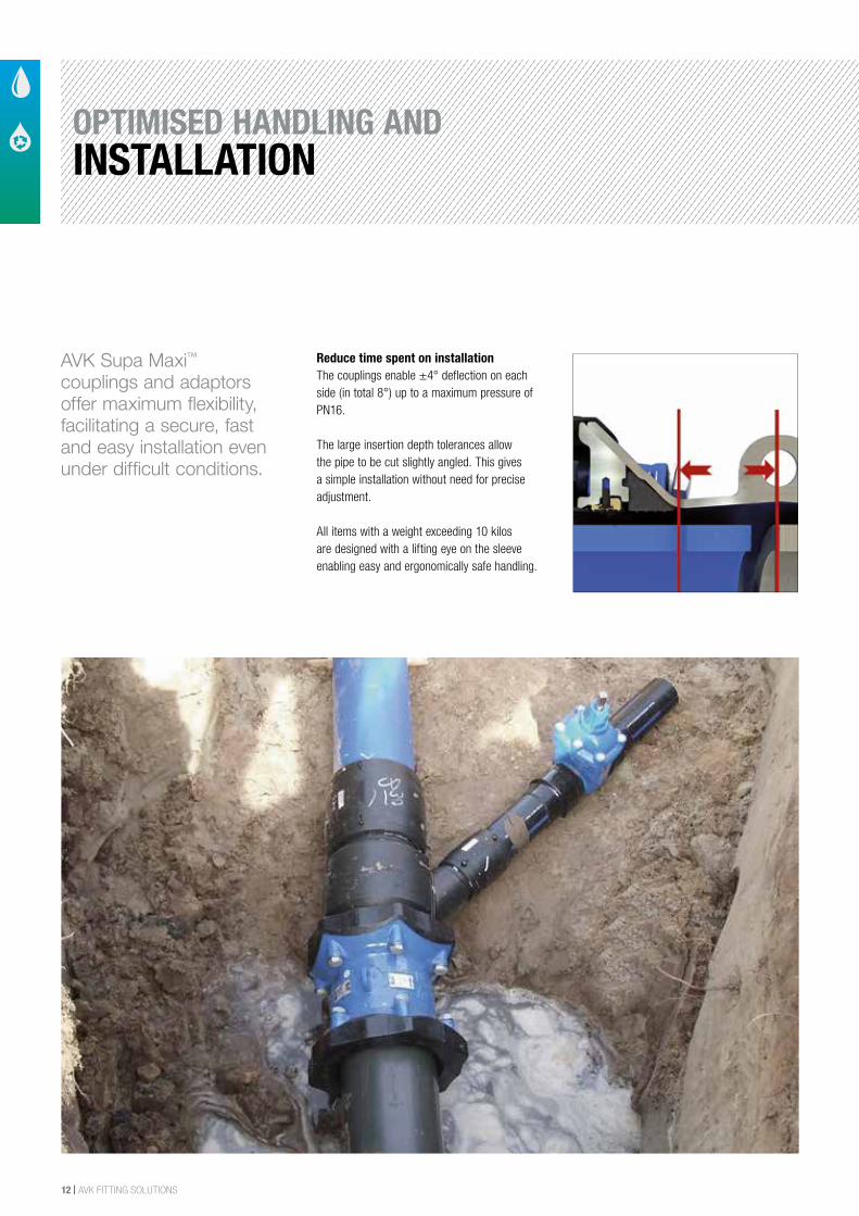
AVK Supa Maxi™ couplings and adaptors offer maximum flexibility, facilitating a secure, fast and easy installation even under difficult conditions.
Reduce time spent on installationThe couplings enable ±4° deflection on each side (in total 8°) up to a maximum pressure of PN16.
The large insertion depth tolerances allow the pipe to be cut slightly angled. This gives a simple installation without need for precise adjustment.
All items with a weight exceeding 10 kilos are designed with a lifting eye on the sleeve enabling easy and ergonomically safe handling.
OPTIMISED HANDLING ANDINSTALLATION
AVK FITTING SOLUTIONS | 13
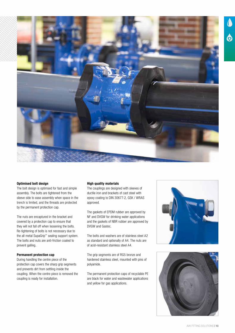
Optimised bolt designThe bolt design is optimsed for fast and simple assembly. The bolts are tightened from the sleeve side to ease assembly when space in the trench is limited, and the threads are protected by the permanent protection cap.
The nuts are encaptured in the bracket and covered by a protection cap to ensure that they will not fall off when loosening the bolts. Re-tightening of bolts is not necessary due to the all metal SupaGrip™ sealing support system. The bolts and nuts are anti-friction coated to prevent galling.
Permanent protection capDuring handling the centre piece of the protection cap covers the sharp grip segments and prevents dirt from settling inside the coupling. When the centre piece is removed the coupling is ready for installation.
High quality materialsThe couplings are designed with sleeves of ductile iron and brackets of cast steel with epoxy coating to DIN 30677-2, GSK / WRAS approved.
The gaskets of EPDM rubber are approved by NF and DVGW for drinking water applications and the gaskets of NBR rubber are approved by DVGW and Gastec.
The bolts and washers are of stainless steel A2 as standard and optionally of A4. The nuts are of acid-resistant stainless steel A4.
The grip segments are of RG5 bronze and hardened stainless steel, mounted with pins of polyamide.
The permanent protection caps of recyclable PE are black for water and wastewater applications and yellow for gas applications.
14 | AVK FITTING SOLUTIONS
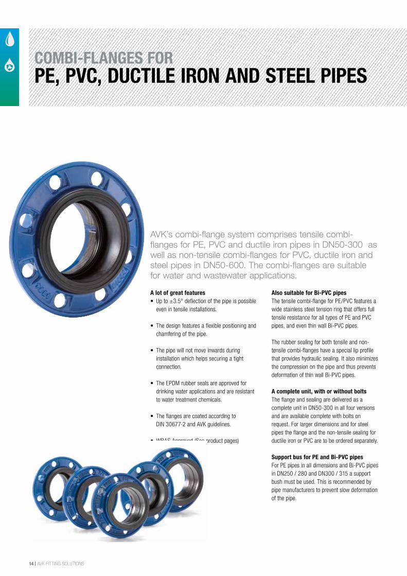
A lot of great features• Up to ±3.5° deflection of the pipe is possible
even in tensile installations.
• The design features a flexible positioning and chamfering of the pipe.
• The pipe will not move inwards during installation which helps securing a tight connection.
• The EPDM rubber seals are approved for drinking water applications and are resistant to water treatment chemicals.
• The flanges are coated according to DIN 30677-2 and AVK guidelines.
• WRAS Approved (See product pages)
Also suitable for Bi-PVC pipesThe tensile combi-flange for PE/PVC features a wide stainless steel tension ring that offers full tensile resistance for all types of PE and PVC pipes, and even thin wall Bi-PVC pipes.
The rubber sealing for both tensile and non-tensile combi-flanges have a special lip profile that provides hydraulic sealing. It also minimizes the compression on the pipe and thus prevents deformation of thin wall Bi-PVC pipes.
A complete unit, with or without boltsThe flange and sealing are delivered as a complete unit in DN50-300 in all four versions and are available complete with bolts on request. For larger dimensions and for steel pipes the flange and the non-tensile sealing for ductile iron or PVC are to be ordered separately.
Support bus for PE and Bi-PVC pipes For PE pipes in all dimensions and Bi-PVC pipes in DN250 / 280 and DN300 / 315 a support bush must be used. This is recommended by pipe manufacturers to prevent slow deformation of the pipe.
AVK’s combi-flange system comprises tensile combi-flanges for PE, PVC and ductile iron pipes in DN50-300 as well as non-tensile combi-flanges for PVC, ductile iron and steel pipes in DN50-600. The combi-flanges are suitable for water and wastewater applications.
COMBI-FLANGES FORPE, PVC, DUCTILE IRON AND STEEL PIPES
AVK FITTING SOLUTIONS | 15
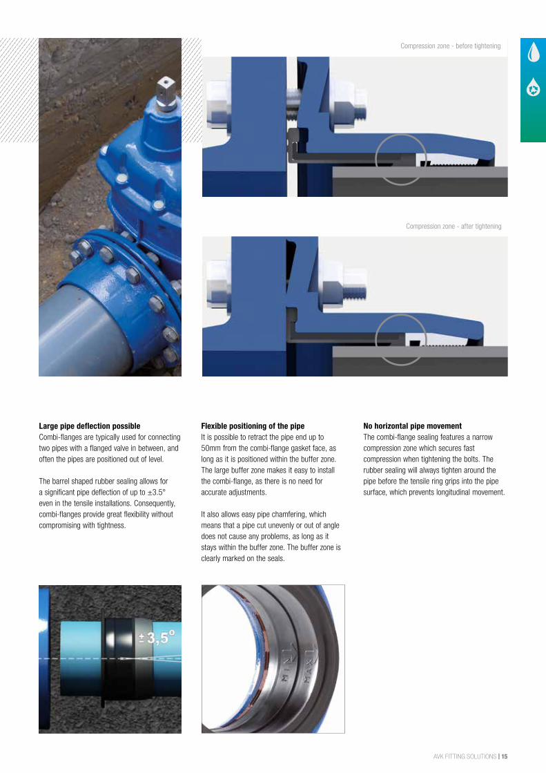
Large pipe deflection possibleCombi-flanges are typically used for connecting two pipes with a flanged valve in between, and often the pipes are positioned out of level.
The barrel shaped rubber sealing allows for a significant pipe deflection of up to ±3.5° even in the tensile installations. Consequently, combi-flanges provide great flexibility without compromising with tightness.
Flexible positioning of the pipeIt is possible to retract the pipe end up to 50mm from the combi-flange gasket face, as long as it is positioned within the buffer zone. The large buffer zone makes it easy to install the combi-flange, as there is no need for accurate adjustments.
It also allows easy pipe chamfering, which means that a pipe cut unevenly or out of angle does not cause any problems, as long as it stays within the buffer zone. The buffer zone is clearly marked on the seals.
No horizontal pipe movement The combi-flange sealing features a narrow compression zone which secures fast compression when tightening the bolts. The rubber sealing will always tighten around the pipe before the tensile ring grips into the pipe surface, which prevents longitudinal movement.
Compression zone - before tightening
Compression zone - after tightening
16 | AVK FITTING SOLUTIONS
Flange adaptorStraight coupling Step coupling
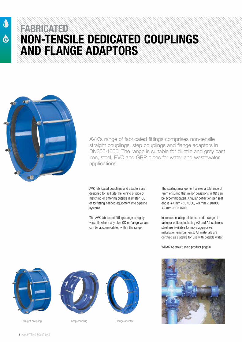
AVK’s range of fabricated fittings comprises non-tensile straight couplings, step couplings and flange adaptors in DN350-1600. The range is suitable for ductile and grey cast iron, steel, PVC and GRP pipes for water and wastewater applications.
AVK fabricated couplings and adaptors are designed to facilitate the joining of pipe of matching or differing outside diameter (OD) or for fitting flanged equipment into pipeline systems.
The AVK fabricated fittings range is highly versatile where any pipe OD or flange variant can be accommodated within the range.
The sealing arrangement allows a tolerance of 7mm ensuring that minor deviations in OD can be accommodated. Angular deflection per seal end is +4 mm < DN600, +3 mm < DN800, +2 mm < DN1600.
Increased coating thickness and a range of fastener options including A2 and A4 stainless steel are available for more aggressive installation environments. All materials are certified as suitable for use with potable water.
WRAS Approved (See product pages)
FABRICATEDNON-TENSILE DEDICATED COUPLINGS AND FLANGE ADAPTORS
AVK FITTING SOLUTIONS | 17
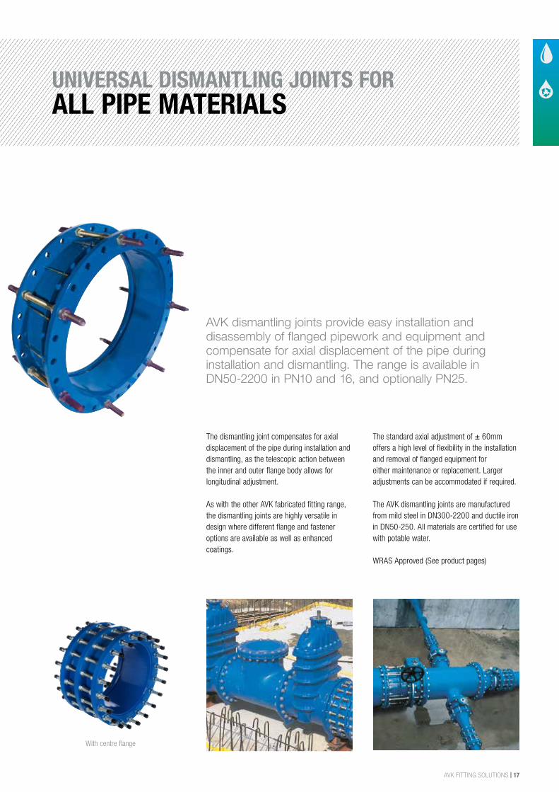
AVK dismantling joints provide easy installation and disassembly of flanged pipework and equipment and compensate for axial displacement of the pipe during installation and dismantling. The range is available in DN50-2200 in PN10 and 16, and optionally PN25.
The dismantling joint compensates for axial displacement of the pipe during installation and dismantling, as the telescopic action between the inner and outer flange body allows for longitudinal adjustment.
As with the other AVK fabricated fitting range, the dismantling joints are highly versatile in design where different flange and fastener options are available as well as enhanced coatings.
The standard axial adjustment of ± 60mm offers a high level of flexibility in the installation and removal of flanged equipment for either maintenance or replacement. Larger adjustments can be accommodated if required.
The AVK dismantling joints are manufactured from mild steel in DN300-2200 and ductile iron in DN50-250. All materials are certified for use with potable water.
WRAS Approved (See product pages)
With centre flange
UNIVERSAL DISMANTLING JOINTS FORALL PIPE MATERIALS
18 | AVK FITTING SOLUTIONS
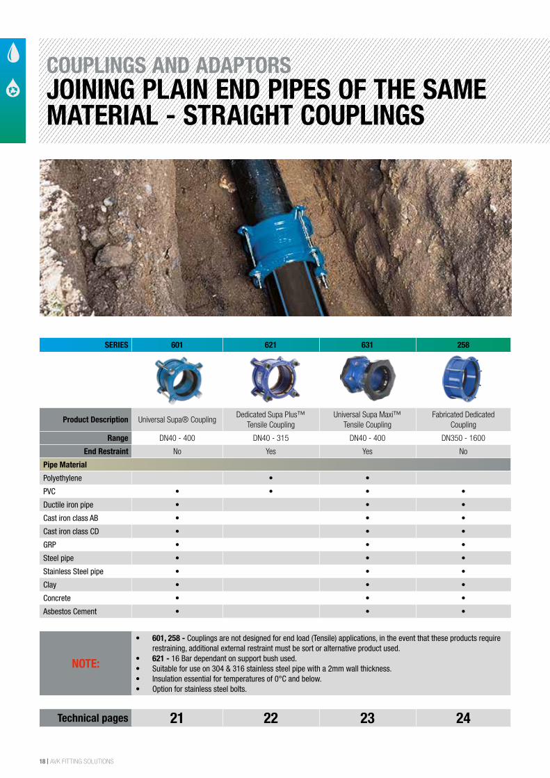
COUPLINGS AND ADAPTORSJOINING PLAIN END PIPES OF THE SAME MATERIAL - STRAIGHT COUPLINGS
SERIES 601 621 631 258
Product Description Universal Supa® CouplingDedicated Supa Plus™
Tensile CouplingUniversal Supa Maxi™
Tensile CouplingFabricated Dedicated
Coupling
Range DN40 - 400 DN40 - 315 DN40 - 400 DN350 - 1600
End Restraint No Yes Yes No
Pipe Material
Polyethylene • •
PVC • • • •
Ductile iron pipe • • •
Cast iron class AB • • •
Cast iron class CD • • •
GRP • • •
Steel pipe • • •
Stainless Steel pipe • • •
Clay • • •
Concrete • • •
Asbestos Cement • • •
NOTE:
• 601, 258 - Couplings are not designed for end load (Tensile) applications, in the event that these products require restraining, additional external restraint must be sort or alternative product used.
• 621 - 16 Bar dependant on support bush used.• Suitable for use on 304 & 316 stainless steel pipe with a 2mm wall thickness.• Insulation essential for temperatures of 0°C and below.• Option for stainless steel bolts.
Technical pages 21 22 23 24
AVK FITTING SOLUTIONS | 19
SIZE
DESCRIPTION
SERIES TYPE
APPLICATION
MAIN FEATURES
MAIN OPTIONS
MAX WORKING PRESSURE
TEMPERATURE RANGE
BODY MATERIAL
APPLICABLE STANDARDS
24/7 SAME DAY EMERGENCY REPAIR CLAMP SERVICE 0800 202 8228
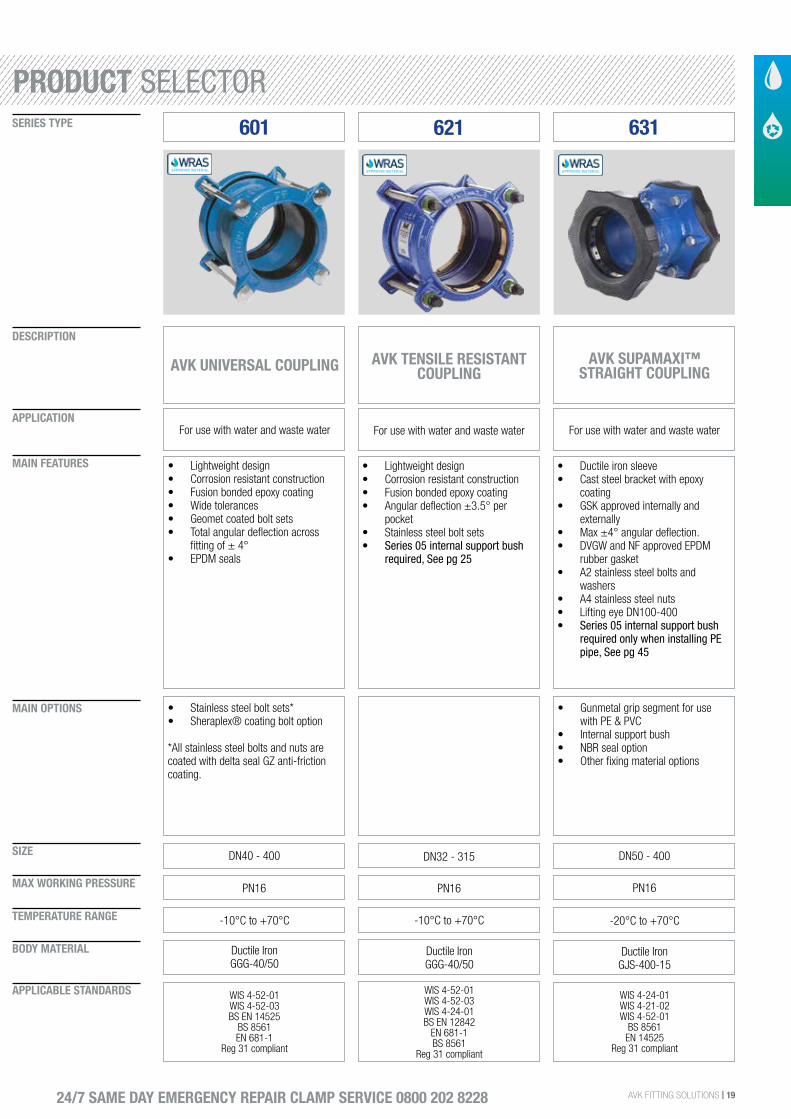
601
AVK UNIVERSAL COUPLING
For use with water and waste water
• Lightweight design• Corrosion resistant construction• Fusion bonded epoxy coating• Wide tolerances• Geomet coated bolt sets• Total angular deflection across
fitting of ± 4°• EPDM seals
DN40 - 400
• Stainless steel bolt sets*• Sheraplex® coating bolt option
*All stainless steel bolts and nuts are coated with delta seal GZ anti-friction coating.
PN16
-10°C to +70°C
Ductile IronGGG-40/50
WIS 4-52-01WIS 4-52-03BS EN 14525
BS 8561EN 681-1
Reg 31 compliant
AVK TENSILE RESISTANT COUPLING
For use with water and waste water
• Lightweight design• Corrosion resistant construction• Fusion bonded epoxy coating• Angular deflection ±3.5° per
pocket• Stainless steel bolt sets• Series 05 internal support bush
required, See pg 25
DN32 - 315
PN16
-10°C to +70°C
Ductile IronGGG-40/50
WIS 4-52-01 WIS 4-52-03WIS 4-24-01BS EN 12842
EN 681-1BS 8561
Reg 31 compliant
621 631
AVK SUPAMAXI™ STRAIGHT COUPLING
For use with water and waste water
• Ductile iron sleeve• Cast steel bracket with epoxy
coating• GSK approved internally and
externally• Max ±4° angular deflection.• DVGW and NF approved EPDM
rubber gasket• A2 stainless steel bolts and
washers• A4 stainless steel nuts• Lifting eye DN100-400• Series 05 internal support bush
required only when installing PE pipe, See pg 45
DN50 - 400
• Gunmetal grip segment for use with PE & PVC
• Internal support bush• NBR seal option• Other fixing material options
PN16
-20°C to +70°C
Ductile Iron GJS-400-15
WIS 4-24-01WIS 4-21-02WIS 4-52-01
BS 8561EN 14525
Reg 31 compliant
PRODUCT SELECTOR
20 | AVK FITTING SOLUTIONS
SIZE
DESCRIPTION
SERIES TYPE
APPLICATION
MAIN FEATURES
MAIN OPTIONS
MAX WORKING PRESSURE
TEMPERATURE RANGE
BODY MATERIAL
APPLICABLE STANDARDS
24/7 SAME DAY EMERGENCY REPAIR CLAMP SERVICE 0800 202 8228
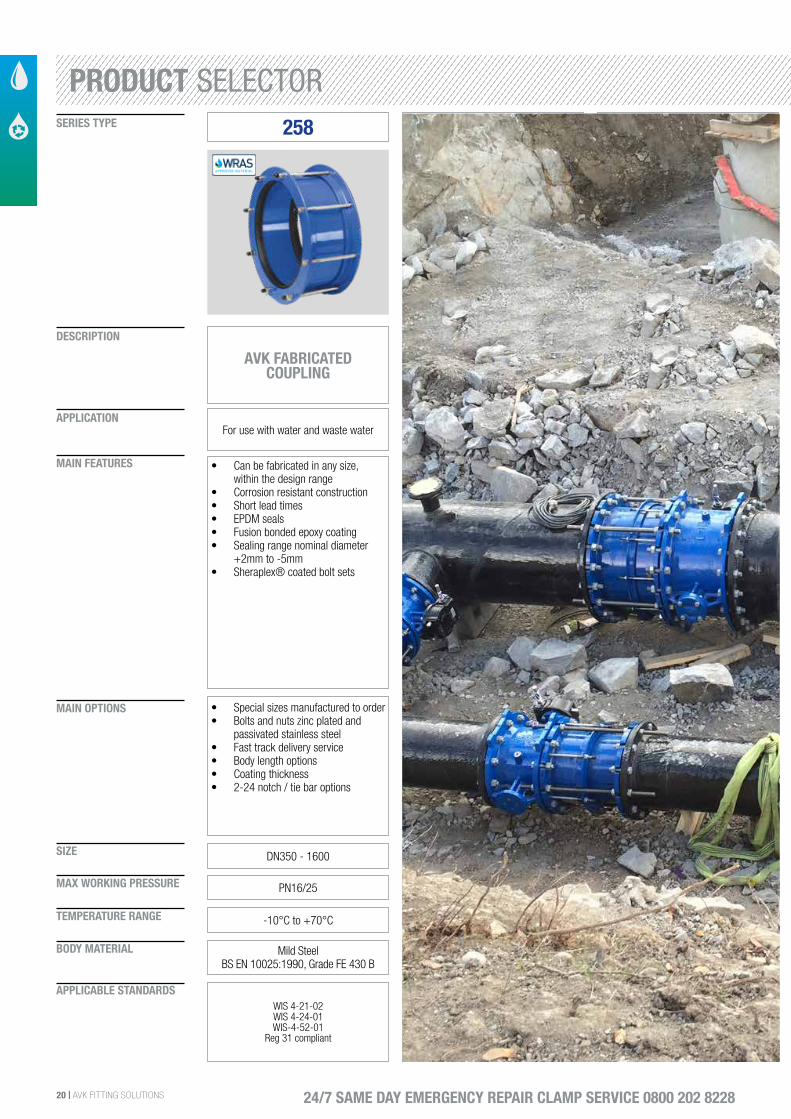
258
AVK FABRICATED COUPLING
For use with water and waste water
• Can be fabricated in any size, within the design range
• Corrosion resistant construction• Short lead times• EPDM seals• Fusion bonded epoxy coating• Sealing range nominal diameter
+2mm to -5mm• Sheraplex® coated bolt sets
DN350 - 1600
• Special sizes manufactured to order• Bolts and nuts zinc plated and
passivated stainless steel• Fast track delivery service• Body length options• Coating thickness• 2-24 notch / tie bar options
PN16/25
-10°C to +70°C
Mild SteelBS EN 10025:1990, Grade FE 430 B
WIS 4-21-02WIS 4-24-01 WIS-4-52-01
Reg 31 compliant
PRODUCT SELECTOR
AVK FITTING SOLUTIONS | 21
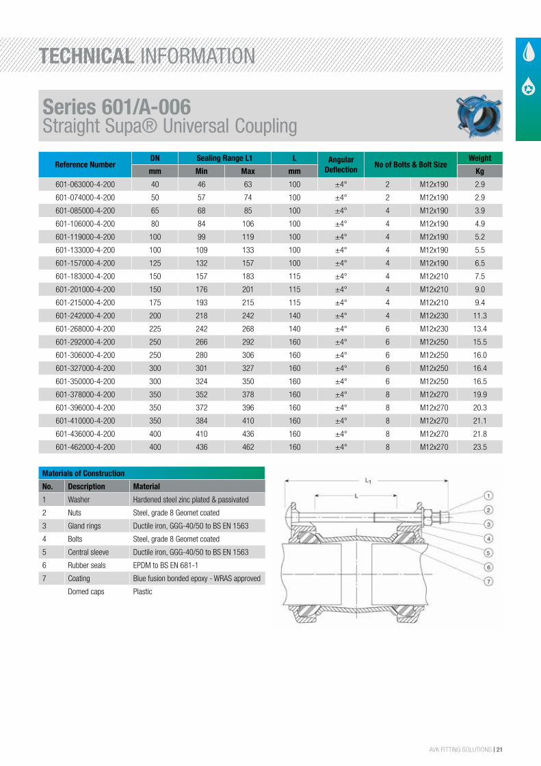
Reference NumberDN Sealing Range L1 L Angular
DeflectionNo of Bolts & Bolt Size
Weight
mm Min Max mm Kg
601-063000-4-200 40 46 63 100 ±4° 2 M12x190 2.9
601-074000-4-200 50 57 74 100 ±4° 2 M12x190 2.9
601-085000-4-200 65 68 85 100 ±4° 4 M12x190 3.9
601-106000-4-200 80 84 106 100 ±4° 4 M12x190 4.9
601-119000-4-200 100 99 119 100 ±4° 4 M12x190 5.2
601-133000-4-200 100 109 133 100 ±4° 4 M12x190 5.5
601-157000-4-200 125 132 157 100 ±4° 4 M12x190 6.5
601-183000-4-200 150 157 183 115 ±4° 4 M12x210 7.5
601-201000-4-200 150 176 201 115 ±4° 4 M12x210 9.0
601-215000-4-200 175 193 215 115 ±4° 4 M12x210 9.4
601-242000-4-200 200 218 242 140 ±4° 4 M12x230 11.3
601-268000-4-200 225 242 268 140 ±4° 6 M12x230 13.4
601-292000-4-200 250 266 292 160 ±4° 6 M12x250 15.5
601-306000-4-200 250 280 306 160 ±4° 6 M12x250 16.0
601-327000-4-200 300 301 327 160 ±4° 6 M12x250 16.4
601-350000-4-200 300 324 350 160 ±4° 6 M12x250 16.5
601-378000-4-200 350 352 378 160 ±4° 8 M12x270 19.9
601-396000-4-200 350 372 396 160 ±4° 8 M12x270 20.3
601-410000-4-200 350 384 410 160 ±4° 8 M12x270 21.1
601-436000-4-200 400 410 436 160 ±4° 8 M12x270 21.8
601-462000-4-200 400 436 462 160 ±4° 8 M12x270 23.5
Materials of Construction
No. Description Material
1 Washer Hardened steel zinc plated & passivated
2 Nuts Steel, grade 8 Geomet coated
3 Gland rings Ductile iron, GGG-40/50 to BS EN 1563
4 Bolts Steel, grade 8 Geomet coated
5 Central sleeve Ductile iron, GGG-40/50 to BS EN 1563
6 Rubber seals EPDM to BS EN 681-1
7 Coating Blue fusion bonded epoxy - WRAS approved
Domed caps Plastic
Series 601/A-006 Straight Supa® Universal Coupling
TECHNICAL INFORMATION
22 | AVK FITTING SOLUTIONS
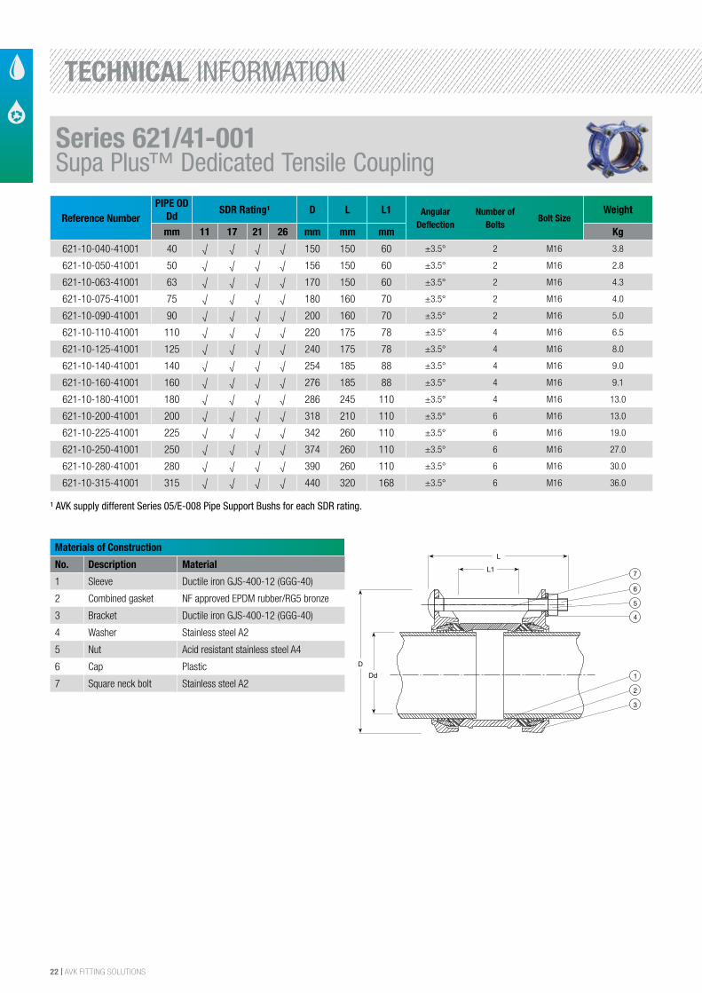
Reference NumberPIPE OD
DdSDR Rating¹ D L L1 Angular
DeflectionNumber of
BoltsBolt Size
Weight
mm 11 17 21 26 mm mm mm Kg
621-10-040-41001 40 √ √ √ √ 150 150 60 ±3.5° 2 M16 3.8
621-10-050-41001 50 √ √ √ √ 156 150 60 ±3.5° 2 M16 2.8
621-10-063-41001 63 √ √ √ √ 170 150 60 ±3.5° 2 M16 4.3
621-10-075-41001 75 √ √ √ √ 180 160 70 ±3.5° 2 M16 4.0
621-10-090-41001 90 √ √ √ √ 200 160 70 ±3.5° 2 M16 5.0
621-10-110-41001 110 √ √ √ √ 220 175 78 ±3.5° 4 M16 6.5
621-10-125-41001 125 √ √ √ √ 240 175 78 ±3.5° 4 M16 8.0
621-10-140-41001 140 √ √ √ √ 254 185 88 ±3.5° 4 M16 9.0
621-10-160-41001 160 √ √ √ √ 276 185 88 ±3.5° 4 M16 9.1
621-10-180-41001 180 √ √ √ √ 286 245 110 ±3.5° 4 M16 13.0
621-10-200-41001 200 √ √ √ √ 318 210 110 ±3.5° 6 M16 13.0
621-10-225-41001 225 √ √ √ √ 342 260 110 ±3.5° 6 M16 19.0
621-10-250-41001 250 √ √ √ √ 374 260 110 ±3.5° 6 M16 27.0
621-10-280-41001 280 √ √ √ √ 390 260 110 ±3.5° 6 M16 30.0
621-10-315-41001 315 √ √ √ √ 440 320 168 ±3.5° 6 M16 36.0
Materials of Construction
No. Description Material
1 Sleeve Ductile iron GJS-400-12 (GGG-40)
2 Combined gasket NF approved EPDM rubber/RG5 bronze
3 Bracket Ductile iron GJS-400-12 (GGG-40)
4 Washer Stainless steel A2
5 Nut Acid resistant stainless steel A4
6 Cap Plastic
7 Square neck bolt Stainless steel A2
The designs, materials and specifications shown are subject to change without notice. This is due to the continuous development of our product programme.
Version no. 71 - 1-29-2016 2:38
AVK SUPA PLUS™ COUPLINGA2 bolt/A4 nut deltaseal, WRAS approved EPDM sealings
621/41001
6
7
5
4
1
2
3
L1
L
Dd
D
Component List:
1. Sleeve Ductile iron GJS-400-12 (GGG-40) 2. Combined gasket NF approved EPDM rubber/RG5 bronze
3. Bracket Ductile iron GJS-400-12 (GGG-40) 4. Washer Stainless steel A2
5. Nut Acid resistant stainless steel A4 6. Cap Plastic
7. Square neck bolt Stainless steel A2
Components may be substituted with equivalent or higher class materials without prior notification.
Reference Nos. and Dimensions:
AVK ref. nosDNmm
Ddmm
D mm
Lmm
L1mm
Theoretic.weight
kg
621-10-040-41001 40 40 150 150 60 3.8621-10-050-41001 40 50 156 150 60 2.8621-10-063-41001 50 63 170 150 60 4.3621-10-075-41001 65 75 180 160 70 4.0621-10-090-41001 80 90 200 160 70 5.0621-10-110-41001 100 110 220 175 78 6.5621-10-125-41001 125 125 240 175 78 8.0621-10-140-41001 125 140 254 185 88 9.0621-10-160-41001 150 160 276 185 88 9.1621-10-180-41001 150 180 286 245 110 13621-10-200-41001 200 200 318 210 110 13621-10-225-41001 200 225 342 260 110 19621-10-250-41001 250 250 374 260 110 27621-10-280-41001 250 280 390 260 110 30621-10-315-41001 300 315 440 320 168 36
PB/12/2
¹ AVK supply different Series 05/E-008 Pipe Support Bushs for each SDR rating.
Series 621/41-001 Supa Plus™ Dedicated Tensile Coupling
TECHNICAL INFORMATION
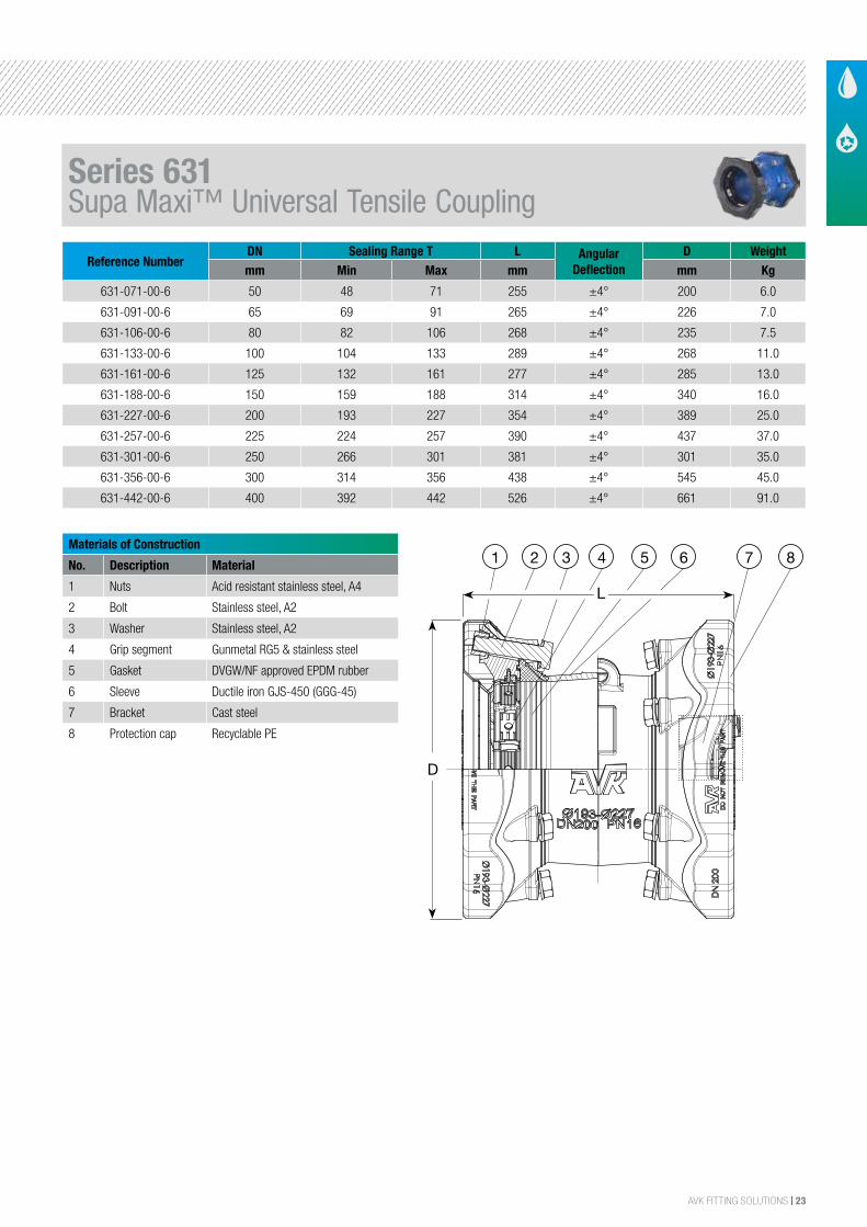
AVK FITTING SOLUTIONS | 23
Reference NumberDN Sealing Range T L Angular
DeflectionD Weight
mm Min Max mm mm Kg
631-071-00-6 50 48 71 255 ±4° 200 6.0
631-091-00-6 65 69 91 265 ±4° 226 7.0
631-106-00-6 80 82 106 268 ±4° 235 7.5
631-133-00-6 100 104 133 289 ±4° 268 11.0
631-161-00-6 125 132 161 277 ±4° 285 13.0
631-188-00-6 150 159 188 314 ±4° 340 16.0
631-227-00-6 200 193 227 354 ±4° 389 25.0
631-257-00-6 225 224 257 390 ±4° 437 37.0
631-301-00-6 250 266 301 381 ±4° 301 35.0
631-356-00-6 300 314 356 438 ±4° 545 45.0
631-442-00-6 400 392 442 526 ±4° 661 91.0
Materials of Construction
No. Description Material
1 Nuts Acid resistant stainless steel, A4
2 Bolt Stainless steel, A2
3 Washer Stainless steel, A2
4 Grip segment Gunmetal RG5 & stainless steel
5 Gasket DVGW/NF approved EPDM rubber
6 Sleeve Ductile iron GJS-450 (GGG-45)
7 Bracket Cast steel
8 Protection cap Recyclable PE
The designs, materials and specifications shown are subject to change without notice. This is due to the continuous development of our product programme.
Version no. 47 - 5-12-2015 3:26
AVK SUPA MAXI™ STRAIGHT COUPLING, PN 16Universal and tensile, A2 bolts, EPDM sealings
631/00001
PRF211
David/1
2/22
/200
9
Prototyp
e: 24
Pos. Description Material Qty
12 Cover PE Low/Medium Density 2
11 Bracket DI EN 1563; GJS-400-15 12
10 Grip ring SS EN 10088-1; (W 1.4112) 12
9 Barbed Push Fasteners PA66 (Polyamide) 24
8 Grip ring Gunmetal RG5 12
7 Bracket Follower DI EN 1563; GJS-400-15 12
6 Brick SS EN 10088-1; (W 1.4401) 24
5 Gasket DN200 Ø193-227 NBR, DIN 3535-3 2
4 Nut M20 12
3 Washer M20 12
2 Bolt M20X90 12
1 Sleeve Straight DI EN 1563; GJS-400-15 1
8
1
2
34
5
6
11
10
12
7
9
XXXXXXXXXXXX
A
11
B C D E F G H I J K L M N O P
10
9
8
7
6
5
4
3
2
1
G I OC PE K MA B D F H J L N
1
10
4
7
2
11
8
5
9
6
3
Dimensions:
Application:
Standards:
Production tests:
Scale:Drawn:
Appr.: Date:
Size:
XXXXXXXXXXXX
XXXXXXXXXXXX
DK-8464 Galten, Denmark
SmTm.:
Drawing No.:
Replace for:
Rev. No.:Projection: Weight:David 1:2
12/22/2009
A1H
SmTm.:
63120000
Kg24.43
AAXXXXXXXXXXX
Soendergade 33AVK HOLDING A/S
form - including manufacture of the product shown therein - without the written consent of AVK.
Supa Maxi StraightSeries 631
227
This drawing is issued by AVK. The drawing is confidential material. It must not be reproduced in any Copyright © 2009 The AVK Group
DN200 193-
XXXXXXXXXXXX
CMYCMMY
CY
CMY
K
631_.pdf 1 16-06-2010 11:46:33
D
7 8654321
L
DN
50 3 x M14 x 75 mm 65 3 x M16 x 75 mm 80 3 x M16 x 75 mm 100 4 x M16 x 75 mm 125 4 x M16 x 75 mm 150 4 x M16 x 90 mm 200 6 x M20 x 100 mm 225 6 x M20 x 100 mm 250 6 x M20 x 100 mm 300 8 x M20 x 100 mm 400 10 x M24 x 120 mm
Component List:
1. Nut Acid resistant stainless steel A4 2. Bolt Stainless steel A2
3. Washer Stainless steel A2 4. Grip segment Gunmetal RG5 and stainless steel
5. Gasket DVGW/NF approved EPDM rubber 6. Sleeve Ductile iron GJS-450 (GGG-45)
7. Bracket Cast steel 8. Protection cap Recyclable PE
Components may be substituted with equivalent or higher class materials without prior notification.
Reference Nos. and Dimensions:
AVK ref. nosDNmm
Product PN Class
Tmm
Lmm
D mm
Theoretic.weight
kg
631-071-00-6 50 PN16 48 - 71 255 200 6.0631-091-00-6 65 PN16 69 - 91 265 226 7.0631-106-00-6 80 PN16 82 - 106 268 235 7.5631-133-00-6 100 PN16 104 - 133 289 268 11631-161-00-6 125 PN16 132 - 161 277 285 13631-188-00-6 150 PN16 159 - 188 314 340 16631-227-00-6 200 PN16 193 - 227 354 389 25631-257-00-6 225 PN16 224 - 257 390 437 37631-301-00-6 250 PN16 266 - 301 381 476 35631-356-00-6 300 PN16 314 - 356 438 545 45631-442-00-6 (1) 400 PN16 392 - 442 526 661 91(1) KIWA approval pending
PB/12/2
Series 631Supa Maxi™ Universal Tensile Coupling
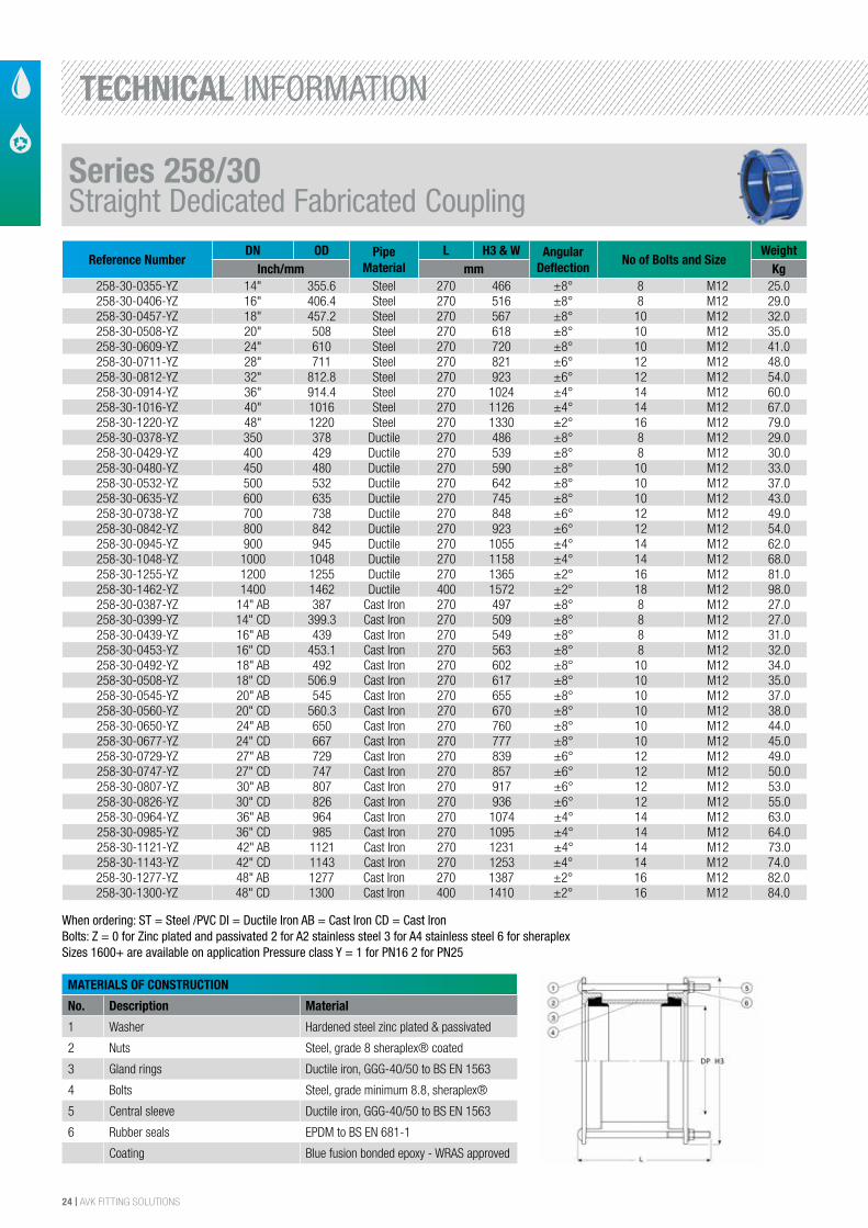
24 | AVK FITTING SOLUTIONS
Reference NumberDN OD Pipe
MaterialL H3 & W Angular
DeflectionNo of Bolts and Size
WeightInch/mm mm Kg
258-30-0355-YZ 14" 355.6 Steel 270 466 ±8° 8 M12 25.0258-30-0406-YZ 16" 406.4 Steel 270 516 ±8° 8 M12 29.0258-30-0457-YZ 18" 457.2 Steel 270 567 ±8° 10 M12 32.0258-30-0508-YZ 20" 508 Steel 270 618 ±8° 10 M12 35.0258-30-0609-YZ 24" 610 Steel 270 720 ±8° 10 M12 41.0258-30-0711-YZ 28" 711 Steel 270 821 ±6° 12 M12 48.0258-30-0812-YZ 32" 812.8 Steel 270 923 ±6° 12 M12 54.0258-30-0914-YZ 36" 914.4 Steel 270 1024 ±4° 14 M12 60.0258-30-1016-YZ 40" 1016 Steel 270 1126 ±4° 14 M12 67.0258-30-1220-YZ 48" 1220 Steel 270 1330 ±2° 16 M12 79.0258-30-0378-YZ 350 378 Ductile 270 486 ±8° 8 M12 29.0258-30-0429-YZ 400 429 Ductile 270 539 ±8° 8 M12 30.0258-30-0480-YZ 450 480 Ductile 270 590 ±8° 10 M12 33.0258-30-0532-YZ 500 532 Ductile 270 642 ±8° 10 M12 37.0258-30-0635-YZ 600 635 Ductile 270 745 ±8° 10 M12 43.0258-30-0738-YZ 700 738 Ductile 270 848 ±6° 12 M12 49.0258-30-0842-YZ 800 842 Ductile 270 923 ±6° 12 M12 54.0258-30-0945-YZ 900 945 Ductile 270 1055 ±4° 14 M12 62.0258-30-1048-YZ 1000 1048 Ductile 270 1158 ±4° 14 M12 68.0258-30-1255-YZ 1200 1255 Ductile 270 1365 ±2° 16 M12 81.0258-30-1462-YZ 1400 1462 Ductile 400 1572 ±2° 18 M12 98.0258-30-0387-YZ 14" AB 387 Cast Iron 270 497 ±8° 8 M12 27.0258-30-0399-YZ 14" CD 399.3 Cast Iron 270 509 ±8° 8 M12 27.0258-30-0439-YZ 16" AB 439 Cast Iron 270 549 ±8° 8 M12 31.0258-30-0453-YZ 16" CD 453.1 Cast Iron 270 563 ±8° 8 M12 32.0258-30-0492-YZ 18" AB 492 Cast Iron 270 602 ±8° 10 M12 34.0258-30-0508-YZ 18" CD 506.9 Cast Iron 270 617 ±8° 10 M12 35.0258-30-0545-YZ 20" AB 545 Cast Iron 270 655 ±8° 10 M12 37.0258-30-0560-YZ 20" CD 560.3 Cast Iron 270 670 ±8° 10 M12 38.0258-30-0650-YZ 24" AB 650 Cast Iron 270 760 ±8° 10 M12 44.0258-30-0677-YZ 24" CD 667 Cast Iron 270 777 ±8° 10 M12 45.0258-30-0729-YZ 27" AB 729 Cast Iron 270 839 ±6° 12 M12 49.0258-30-0747-YZ 27" CD 747 Cast Iron 270 857 ±6° 12 M12 50.0258-30-0807-YZ 30" AB 807 Cast Iron 270 917 ±6° 12 M12 53.0258-30-0826-YZ 30" CD 826 Cast Iron 270 936 ±6° 12 M12 55.0258-30-0964-YZ 36" AB 964 Cast Iron 270 1074 ±4° 14 M12 63.0258-30-0985-YZ 36" CD 985 Cast Iron 270 1095 ±4° 14 M12 64.0258-30-1121-YZ 42" AB 1121 Cast Iron 270 1231 ±4° 14 M12 73.0258-30-1143-YZ 42" CD 1143 Cast Iron 270 1253 ±4° 14 M12 74.0258-30-1277-YZ 48" AB 1277 Cast Iron 270 1387 ±2° 16 M12 82.0258-30-1300-YZ 48" CD 1300 Cast Iron 400 1410 ±2° 16 M12 84.0
MATERIALS OF CONSTRUCTION
No. Description Material
1 Washer Hardened steel zinc plated & passivated
2 Nuts Steel, grade 8 sheraplex® coated
3 Gland rings Ductile iron, GGG-40/50 to BS EN 1563
4 Bolts Steel, grade minimum 8.8, sheraplex®
5 Central sleeve Ductile iron, GGG-40/50 to BS EN 1563
6 Rubber seals EPDM to BS EN 681-1
Coating Blue fusion bonded epoxy - WRAS approved
When ordering: ST = Steel /PVC DI = Ductile Iron AB = Cast Iron CD = Cast IronBolts: Z = 0 for Zinc plated and passivated 2 for A2 stainless steel 3 for A4 stainless steel 6 for sheraplexSizes 1600+ are available on application Pressure class Y = 1 for PN16 2 for PN25
Series 258/30Straight Dedicated Fabricated Coupling
TECHNICAL INFORMATION
AVK FITTING SOLUTIONS | 25
26 | AVK FITTING SOLUTIONS
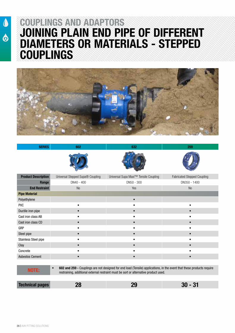
COUPLINGS AND ADAPTORSJOINING PLAIN END PIPE OF DIFFERENT DIAMETERS OR MATERIALS - STEPPED COUPLINGS
SERIES 602 632 259
Product Description Universal Stepped Supa® Coupling Universal Supa Maxi™ Tensile Coupling Fabricated Stepped Coupling
Range DN40 - 400 DN50 - 300 DN350 - 1400
End Restraint No Yes No
Pipe Material
Polyethylene •
PVC • • •
Ductile iron pipe • • •
Cast iron class AB • • •
Cast iron class CD • • •
GRP • • •
Steel pipe • • •
Stainless Steel pipe • • •
Clay • • •
Concrete • • •
Asbestos Cement • • •
NOTE: • 602 and 259 - Couplings are not designed for end load (Tensile) applications, in the event that these products require restraining, additional external restraint must be sort or alternative product used.
Technical pages 28 29 30 - 31
AVK FITTING SOLUTIONS | 27
SIZE
DESCRIPTION
SERIES TYPE
APPLICATION
MAIN FEATURES
MAIN OPTIONS
MAX WORKING PRESSURE
TEMPERATURE RANGE
BODY MATERIAL
APPLICABLE STANDARDS
24/7 SAME DAY EMERGENCY REPAIR CLAMP SERVICE 0800 202 8228
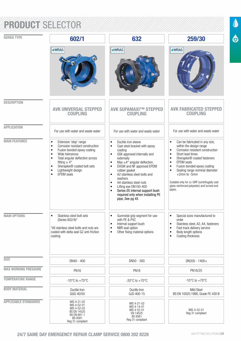
602/1
AVK UNIVERSAL STEPPED COUPLING
For use with water and waste water
• Extensive ‘step’ range• Corrosion resistant construction• Fusion bonded epoxy coating• Wide tolerances• Total angular deflection across
fitting ± 4°• Sheraplex® coated bolt sets• Lightweight design• EPDM seals
DN40 - 400
• Stainless steel bolt sets (Series 602/4)*
*All stainless steel bolts and nuts are coated with delta seal GZ anti-friction coating.
PN16
-10°C to +70°C
Ductile IronGGG-40/50
WIS 4-21-02WIS 4-52-01WIS 4-52-03BS EN 14525BS EN 681-1
BS 8561Reg 31 compliant
259/30
AVK FABRICATED STEPPED COUPLING
For use with water and waste water
• Can be fabricated in any size, within the design range
• Corrosion resistant construction• Short lead times• Sheraplex® coated fasteners• EPDM seals• Fusion bonded epoxy coating• Sealing range nominal diameter
+2mm to -5mm
Suitable only for cc-GRP (centrifugally cast glass reinforced polyester) and turned end pipes.
DN350 - 1400+
• Special sizes manufactured to order
• Stainless steel, A2, A4, fasteners• Fast track delivery service• Body length options• Coating thickness
PN16/25
-10°C to +70°C
Mild Steel BS EN 10025:1990, Grade FE 430 B
WIS-4-52-01Reg 31 compliant
632
AVK SUPAMAXI™ STEPPED COUPLING
For use with water and waste water
• Ductile iron sleeve• Cast steel bracket with epoxy
coating• GSK approved internally and
externally• Max ±4° angular deflection.• DVGW and NF approved EPDM
rubber gasket• A2 stainless steel bolts and
washers• A4 stainless steel nuts• Lifting eye DN100-400• Series 05 internal support bush
required only when installing PE pipe, See pg 45
DN50 - 300
• Gunmetal grip segment for use with PE & PVC
• Internal support bush• NBR seal option• Other fixing material options
PN16
-20°C to +70°C
Ductile Iron GJS-400-15
WIS 4-21-02WIS 4-14-01WIS 4-52-01
EN 14525BS 8561
Reg 31 compliant
PRODUCT SELECTOR
28 | AVK FITTING SOLUTIONS
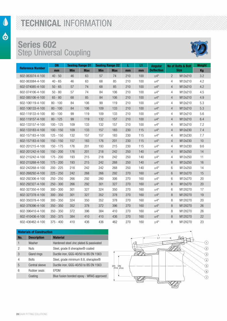
Reference NumberDN Sealing Range D1 Sealing Range D2 L L1 Angular
DeflectionNo of Bolts & Bolt
SizeWeight
mm Min Max Min Max mm mm Kg
602-063074-4-100 40 - 50 46 63 57 74 210 100 ±4° 2 M12x210 3.2
602-063084-4-100 40 - 65 46 63 68 85 210 100 ±4° 4 M12x210 4.2
602-074085-4-100 50 - 65 57 74 68 85 210 100 ±4° 4 M12x210 4.2
602-074106-4-100 50 - 80 57 74 84 106 210 100 ±4° 4 M12x210 4.5
602-085106-4-100 65 - 80 68 85 84 106 210 100 ±4° 4 M12x210 4.9
602-106119-4-100 80 - 100 84 106 99 119 210 100 ±4° 4 M12x210 5.3
602-106133-4-100 80 - 100 84 106 109 133 210 100 ±4° 4 M12x210 5.3
602-119133-4-100 80 - 100 99 119 109 133 210 100 ±4° 4 M12x210 5.6
602-119157-4-100 80 - 125 99 119 132 157 210 100 ±4° 4 M12x210 6.4
602-133157-4-100 100 - 125 109 133 132 157 210 100 ±4° 4 M12x210 7.2
602-133183-4-100 100 - 150 109 133 157 183 230 115 ±4° 4 M12x230 7.4
602-157183-4-100 125 - 150 132 157 157 183 230 115 ±4° 4 M12x230 7.7
602-157183-4-100 150 - 150 157 183 176 201 230 115 ±4° 4 M12x230 10
602-201215-4-100 150 - 175 176 201 193 215 230 115 ±4° 4 M12x230 9.6
602-201242-4-100 150 - 200 176 201 218 242 250 140 ±4° 4 M12x250 14
602-215242-4-100 175 - 200 193 215 218 242 250 140 ±4° 4 M12x250 11
602-215268-4-100 175 - 200 193 215 242 268 250 140 ±4° 6 M12x250 16
602-242268-4-100 200 - 225 218 242 242 268 250 140 ±4° 6 M12x250 14
602-268292-4-100 225 - 250 242 268 266 292 270 160 ±4° 6 M12x270 15
602-292306-4-100 250 - 250 266 292 280 306 270 160 ±4° 6 M12x270 20
602-292327-4-100 250 - 300 266 292 301 327 270 160 ±4° 6 M12x270 20
602-327350-4-100 300 - 300 301 327 324 350 270 160 ±4° 6 M12X270 17
602-327378-4-100 300 - 350 301 327 352 378 270 160 ±4° 8 M12X270 19
602-350378-4-100 300 - 350 324 350 352 378 270 160 ±4° 8 M12X270 20
602-378396-4-100 350 - 350 352 378 372 396 270 160 ±4° 8 M12X270 26
602-396410-4-100 350 - 350 372 396 384 410 270 160 ±4° 8 M12X270 26
602-410436-4-100 350 - 375 384 410 410 436 270 160 ±4° 8 M12X270 22
602-436462-4-100 375 - 400 410 436 436 462 270 160 ±4° 8 M12X270 23
Materials of Construction
No. Description Material
1 Washer Hardened steel zinc plated & passivated
2 Nuts Steel, grade 8 sheraplex® coated
3 Gland rings Ductile iron, GGG-40/50 to BS EN 1563
4 Bolts Steel, grade minimum 8.8, sheraplex®
5 Central sleeve Ductile iron, GGG-40/50 to BS EN 1563
6 Rubber seals EPDM
Coating Blue fusion bonded epoxy - WRAS approved
The designs, materials and specifications shown are subject to change without notice. This is due to the continuous development of our product programme.
Version no. 65 - 2-17-2016 9:47
AVK UNIVERSAL SUPA® STEP COUPLINGMild steel Sheraplex bolts/nuts, WRAS approved EPDM sealings
602/1001
1
2
3
4
5
6
7
L1
DNDN
L
(PC2)(PC3)
Component List:
1. Protection cap Plastic 2. Washer Zinc plated hardened steel
3. Nut Acid-resistant stainless steel A4 4. Bolt Stainless steel A2
5. Gland ring Ductile iron GJS-400-12 (GGG-40) 6. Gasket EPDM rubber
7. Centre sleeve Ductile iron GJS-400-12 (GGG-40)
Components may be substituted with equivalent or higher class materials without prior notification.
Reference Nos. and Dimensions:
AVK ref. nosDN/DN
mmL
mmL1
mmSealing Range
mmPipecover
Theoretic.weight
kg
602-063-074-4100 40 - 50 210 100 46 - 63 57 - 74 3.2602-063-085-4100 40 - 65 210 100 46 - 63 68 - 85 4.2602-074-085-4100 50 - 65 210 100 57 - 74 68 - 85 4.2602-074-106-4100 50 - 80 210 100 57 - 74 84 - 106 4.5602-085-106-4100 65 - 80 210 100 68 - 85 84 - 106 4.9602-106-119-4100 80 - 100 210 100 84 - 106 99 - 119 5.3602-106-133-4100 80 - 100 210 100 84 - 106 109 - 133 5.3602-119-133-4100 80 - 100 210 100 99 - 119 109 - 133 5.6602-119-157-4100 80 - 125 210 100 99 - 119 132 - 157 6.4602-133-157-4100 100 - 125 210 100 109 - 133 132 - 157 7.2602-133-183-4100 100 - 150 230 115 109 - 133 157 - 183 7.4602-157-183-4100 125 - 150 230 115 132 - 157 157 - 183 7.7602-183-201-4100 150 - 150 230 115 157 - 183 176 - 201 10602-201-215-4100 150 - 175 230 115 176 - 201 193 - 215 9.6602-201-242-4100 175 - 200 250 140 176 - 201 218 - 242 14602-215-242-4100 175 - 200 250 140 193 - 215 218 - 242 11602-215-268-4100 175 - 225 250 140 193 - 215 242 - 268 16602-242-268-4100 200 - 225 250 140 218 - 242 242 - 268 14602-268-292-4100 225 - 250 270 160 242 - 268 266 - 292 15
3/33/32/3
Series 602Step Universal Coupling
TECHNICAL INFORMATION
AVK FITTING SOLUTIONS | 29
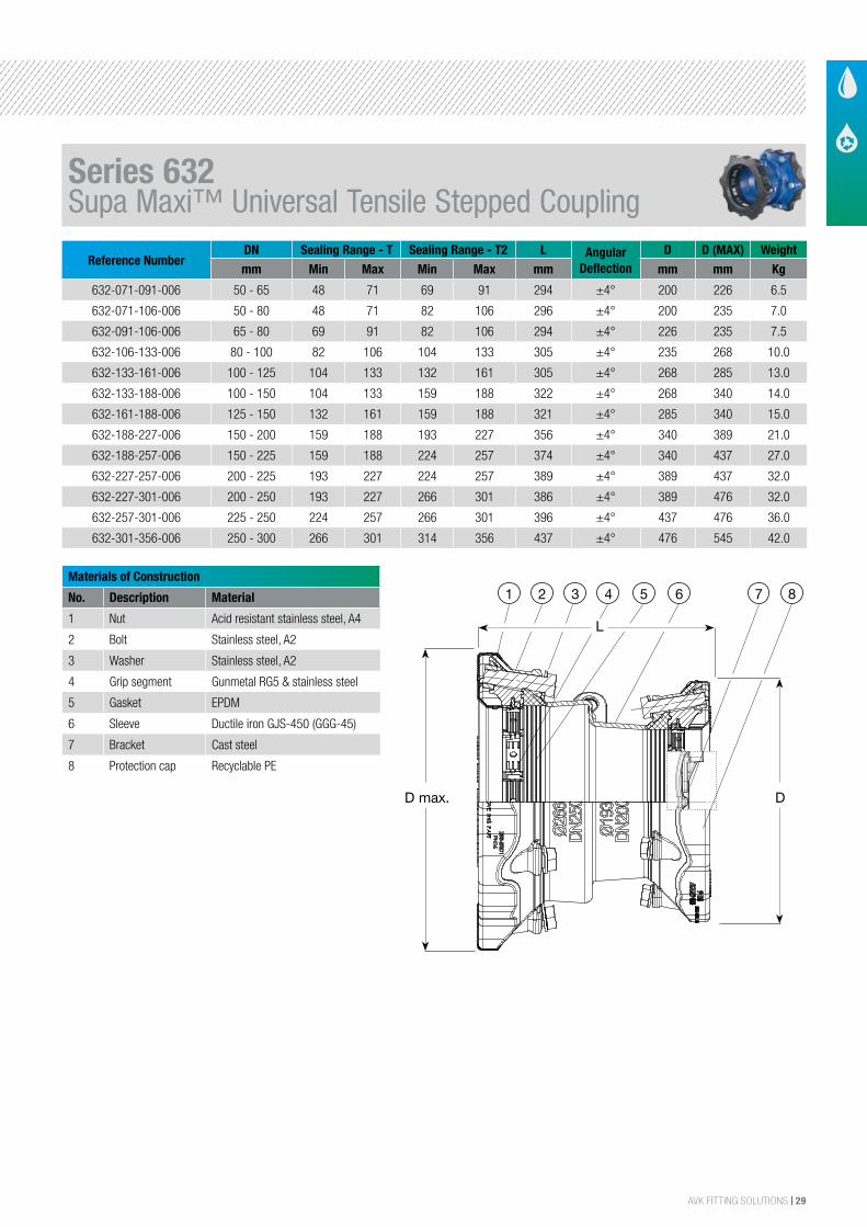
Reference NumberDN Sealing Range - T Sealing Range - T2 L Angular
DeflectionD D (MAX) Weight
mm Min Max Min Max mm mm mm Kg
632-071-091-006 50 - 65 48 71 69 91 294 ±4° 200 226 6.5
632-071-106-006 50 - 80 48 71 82 106 296 ±4° 200 235 7.0
632-091-106-006 65 - 80 69 91 82 106 294 ±4° 226 235 7.5
632-106-133-006 80 - 100 82 106 104 133 305 ±4° 235 268 10.0
632-133-161-006 100 - 125 104 133 132 161 305 ±4° 268 285 13.0
632-133-188-006 100 - 150 104 133 159 188 322 ±4° 268 340 14.0
632-161-188-006 125 - 150 132 161 159 188 321 ±4° 285 340 15.0
632-188-227-006 150 - 200 159 188 193 227 356 ±4° 340 389 21.0
632-188-257-006 150 - 225 159 188 224 257 374 ±4° 340 437 27.0
632-227-257-006 200 - 225 193 227 224 257 389 ±4° 389 437 32.0
632-227-301-006 200 - 250 193 227 266 301 386 ±4° 389 476 32.0
632-257-301-006 225 - 250 224 257 266 301 396 ±4° 437 476 36.0
632-301-356-006 250 - 300 266 301 314 356 437 ±4° 476 545 42.0
Materials of Construction
No. Description Material
1 Nut Acid resistant stainless steel, A4
2 Bolt Stainless steel, A2
3 Washer Stainless steel, A2
4 Grip segment Gunmetal RG5 & stainless steel
5 Gasket EPDM
6 Sleeve Ductile iron GJS-450 (GGG-45)
7 Bracket Cast steel
8 Protection cap Recyclable PE
The designs, materials and specifications shown are subject to change without notice. This is due to the continuous development of our product programme.
Version no. 70 - 5-12-2015 3:36
AVK SUPA MAXI™ STEP COUPLING, PN 16Universal and tensile, A2 bolts, EPDM sealings
632/00001
CMYCMMY
CY
CMY
K
632.pdf 1 02-05-2011 14:38:11
D max.
7 8654321
CMYCMMY
CY
CMY
K
631_.pdf 1 16-06-2010 11:46:33
D
L
DN
50 3 x M14 x 75 mm 65 3 x M16 x 75 mm 80 3 x M16 x 75 mm 100 4 x M16 x 75 mm 125 4 x M16 x 75 mm 150 4 x M16 x 90 mm 200 6 x M20 x 100 mm 225 6 x M20 x 100 mm 250 6 x M20 x 100 mm 300 8 x M20 x 100 mm
Component List:
1. Nut Acid resistant stainless steel A4 2. Bolt Stainless steel A2
3. Washer Stainless steel A2 4. Grip segment Gunmetal RG5 and stainless steel
5. Gasket DVGW/NF approved EPDM rubber 6. Sleeve Ductile iron GJS-450 (GGG-45)
7. Bracket Cast steel 8. Protection cap Recyclable PE
Components may be substituted with equivalent or higher class materials without prior notification.
Reference Nos. and Dimensions:
AVK ref. nosDN/DN
mmProduct
PN ClassT
mmT2
mmL
mmD
mm
D max mm
Theoretic.weight
kg
632-071-091-006 50 - 65 PN16 48 - 71 69 - 91 294 200 226 6.5632-071-106-006 50 - 80 PN16 48 - 71 82 - 106 296 200 235 7.0632-091-106-006 65 - 80 PN16 69 - 91 82 - 106 294 226 235 7.5632-106-133-006 80 - 100 PN16 82 - 106 104 - 133 305 235 268 10632-133-161-006 100 - 125 PN16 104 - 133 132 - 161 305 268 285 13632-133-188-006 100 - 150 PN16 104 - 133 159 - 188 322 268 340 14632-161-188-006 125 - 150 PN16 132 - 161 159 - 188 321 285 340 15632-188-227-006 150 - 200 PN16 159 - 188 193 - 227 356 340 389 21632-188-257-006 150 - 225 PN16 159 - 188 224 - 257 374 340 437 27632-227-257-006 200 - 225 PN16 193 - 227 224 - 257 389 389 437 32632-227-301-006 200 - 250 PN16 193 - 227 266 - 301 386 389 476 32632-257-301-006 225 - 250 PN16 224 - 257 266 - 301 396 437 476 36632-301-356-006 250 - 300 PN16 266 - 301 314 - 356 437 476 545 42
PB/12/2
Series 632Supa Maxi™ Universal Tensile Stepped Coupling
30 | AVK FITTING SOLUTIONS
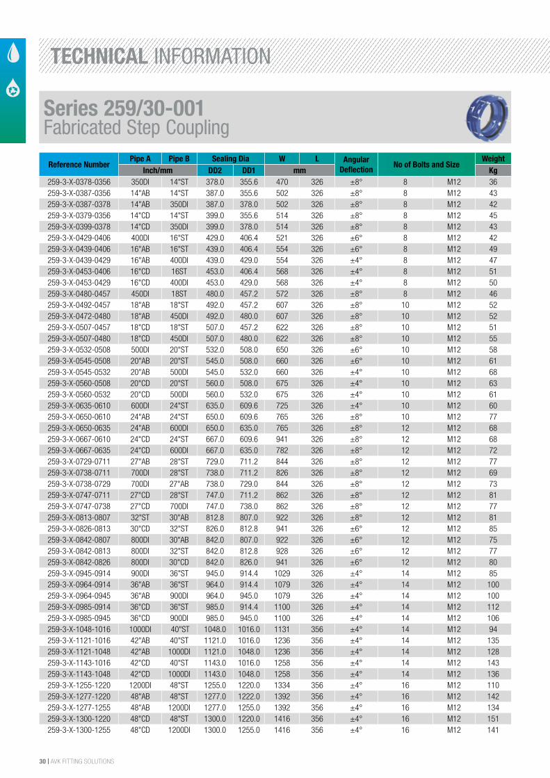
Reference NumberPipe A Pipe B Sealing Dia W L Angular
DeflectionNo of Bolts and Size
WeightInch/mm DD2 DD1 mm Kg
259-3-X-0378-0356 350DI 14"ST 378.0 355.6 470 326 ±8° 8 M12 36259-3-X-0387-0356 14"AB 14"ST 387.0 355.6 502 326 ±8° 8 M12 43259-3-X-0387-0378 14"AB 350DI 387.0 378.0 502 326 ±8° 8 M12 42259-3-X-0379-0356 14"CD 14"ST 399.0 355.6 514 326 ±8° 8 M12 45259-3-X-0399-0378 14"CD 350DI 399.0 378.0 514 326 ±8° 8 M12 43259-3-X-0429-0406 400DI 16"ST 429.0 406.4 521 326 ±6° 8 M12 42259-3-X-0439-0406 16"AB 16"ST 439.0 406.4 554 326 ±6° 8 M12 49259-3-X-0439-0429 16"AB 400DI 439.0 429.0 554 326 ±4° 8 M12 47259-3-X-0453-0406 16"CD 16ST 453.0 406.4 568 326 ±4° 8 M12 51259-3-X-0453-0429 16"CD 400DI 453.0 429.0 568 326 ±4° 8 M12 50259-3-X-0480-0457 450DI 18ST 480.0 457.2 572 326 ±8° 8 M12 46259-3-X-0492-0457 18"AB 18"ST 492.0 457.2 607 326 ±8° 10 M12 52259-3-X-0472-0480 18"AB 450DI 492.0 480.0 607 326 ±8° 10 M12 52259-3-X-0507-0457 18"CD 18"ST 507.0 457.2 622 326 ±8° 10 M12 51259-3-X-0507-0480 18"CD 450DI 507.0 480.0 622 326 ±8° 10 M12 55259-3-X-0532-0508 500DI 20"ST 532.0 508.0 650 326 ±6° 10 M12 58259-3-X-0545-0508 20"AB 20"ST 545.0 508.0 660 326 ±6° 10 M12 61259-3-X-0545-0532 20"AB 500DI 545.0 532.0 660 326 ±4° 10 M12 68259-3-X-0560-0508 20"CD 20"ST 560.0 508.0 675 326 ±4° 10 M12 63259-3-X-0560-0532 20"CD 500DI 560.0 532.0 675 326 ±4° 10 M12 61259-3-X-0635-0610 600DI 24"ST 635.0 609.6 725 326 ±4° 10 M12 60259-3-X-0650-0610 24"AB 24"ST 650.0 609.6 765 326 ±8° 10 M12 77259-3-X-0650-0635 24"AB 600DI 650.0 635.0 765 326 ±8° 12 M12 68259-3-X-0667-0610 24"CD 24"ST 667.0 609.6 941 326 ±8° 12 M12 68259-3-X-0667-0635 24"CD 600DI 667.0 635.0 782 326 ±8° 12 M12 72259-3-X-0729-0711 27"AB 28"ST 729.0 711.2 844 326 ±8° 12 M12 77259-3-X-0738-0711 700DI 28"ST 738.0 711.2 826 326 ±8° 12 M12 69259-3-X-0738-0729 700DI 27"AB 738.0 729.0 844 326 ±8° 12 M12 73259-3-X-0747-0711 27"CD 28"ST 747.0 711.2 862 326 ±8° 12 M12 81259-3-X-0747-0738 27"CD 700DI 747.0 738.0 862 326 ±8° 12 M12 77259-3-X-0813-0807 32"ST 30"AB 812.8 807.0 922 326 ±8° 12 M12 81259-3-X-0826-0813 30"CD 32"ST 826.0 812.8 941 326 ±6° 12 M12 85259-3-X-0842-0807 800DI 30"AB 842.0 807.0 922 326 ±6° 12 M12 75259-3-X-0842-0813 800DI 32"ST 842.0 812.8 928 326 ±6° 12 M12 77259-3-X-0842-0826 800DI 30"CD 842.0 826.0 941 326 ±6° 12 M12 80259-3-X-0945-0914 900DI 36"ST 945.0 914.4 1029 326 ±4° 14 M12 85259-3-X-0964-0914 36"AB 36"ST 964.0 914.4 1079 326 ±4° 14 M12 100259-3-X-0964-0945 36"AB 900DI 964.0 945.0 1079 326 ±4° 14 M12 100259-3-X-0985-0914 36"CD 36"ST 985.0 914.4 1100 326 ±4° 14 M12 112259-3-X-0985-0945 36"CD 900DI 985.0 945.0 1100 326 ±4° 14 M12 106259-3-X-1048-1016 1000DI 40"ST 1048.0 1016.0 1131 356 ±4° 14 M12 94259-3-X-1121-1016 42"AB 40"ST 1121.0 1016.0 1236 356 ±4° 14 M12 135259-3-X-1121-1048 42"AB 1000DI 1121.0 1048.0 1236 356 ±4° 14 M12 128259-3-X-1143-1016 42"CD 40"ST 1143.0 1016.0 1258 356 ±4° 14 M12 143259-3-X-1143-1048 42"CD 1000DI 1143.0 1048.0 1258 356 ±4° 14 M12 136259-3-X-1255-1220 1200DI 48"ST 1255.0 1220.0 1334 356 ±4° 16 M12 110259-3-X-1277-1220 48"AB 48"ST 1277.0 1222.0 1392 356 ±4° 16 M12 142259-3-X-1277-1255 48"AB 1200DI 1277.0 1255.0 1392 356 ±4° 16 M12 134259-3-X-1300-1220 48"CD 48"ST 1300.0 1220.0 1416 356 ±4° 16 M12 151259-3-X-1300-1255 48"CD 1200DI 1300.0 1255.0 1416 356 ±4° 16 M12 141
Series 259/30-001Fabricated Step Coupling
TECHNICAL INFORMATION
AVK FITTING SOLUTIONS | 31
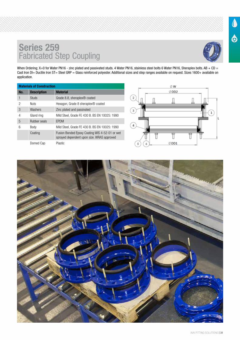
Materials of Construction
No. Description Material
1 Studs Grade 8.8, sheraplex® coated
2 Nuts Hexagon, Grade 8 sheraplex® coated
3 Washers Zinc plated and passivated
4 Gland ring Mild Steel, Grade FE 430 B. BS EN 10025: 1990
5 Rubber seals EPDM
6 Body Mild Steel, Grade FE 430 B. BS EN 10025: 1990
Coating Fusion Bonded Epoxy Coating WIS 4-52-01 or wet sprayed dependent upon size. WRAS approved
Domed Cap Plastic
When Ordering; X=0 for Water PN16 - zinc plated and passivated studs. 4 Water PN16, stainless steel bolts 6 Water PN16, Sheraplex bolts. AB + CD =Cast Iron DI= Ductile Iron ST= Steel GRP = Glass reinforced polyester. Additional sizes and step ranges available on request. Sizes 1600+ available on application.
Series 259Fabricated Step Coupling
32 | AVK FITTING SOLUTIONS
SERIES 603 603/4 623 633 260/30 05/26 05/60 209/30
Product Description
Universal Supa® Flange Adaptor
Universal Dedicated
Flange Adaptor
Dedicated Supa Plus™
Tensile Flange Adaptor
Universal Supa Maxi™
Tensile Flange Adaptor
Fabricated Dedicated
Flange Adaptor
Combi-FlangeCombi Tensile
FlangeFlange
Convertor
Range DN40 - 400 DN80 - 200 DN40 - 315 DN40 - 400 DN350 -2000 DN50 - 300 DN80 - 300 DN80 - 350
Flange DrillingPN10/16/25,
BS 10PN10/16/25,
BS 10PN10/16/25 PN10/16/25
PN10/16/25, BS 10
PN10/16 PN10/16 PN10/16
End Restraint No No Yes Yes No Yes Yes No
Pipe Material
Polyethylene • • • •
PVC • • • • • • •
Ductile iron pipe • • • • • • •
Cast iron class AB • • • • •
Cast iron class CD • • • • •
GRP • • • • •
Steel pipe • • • • • • •
Stainless Steel pipe • • • • •
Clay • • • • •
Concrete • • • • •
Asbestos Cement • • • • •
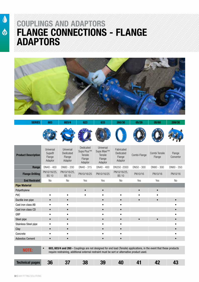
NOTE: • 603, 603/4 and 260 - Couplings are not designed for end load (Tensile) applications, in the event that these products require restraining, additional external restraint must be sort or alternative product used.
Technical pages 36 37 38 39 40 41 42 43
COUPLINGS AND ADAPTORSFLANGE CONNECTIONS - FLANGE ADAPTORS
AVK FITTING SOLUTIONS | 33
SIZE
DESCRIPTION
SERIES TYPE
APPLICATION
MAIN FEATURES
MAIN OPTIONS
MAX WORKING PRESSURE
TEMPERATURE RANGE
BODY MATERIAL
APPLICABLE STANDARDS
24/7 SAME DAY EMERGENCY REPAIR CLAMP SERVICE 0800 202 8228
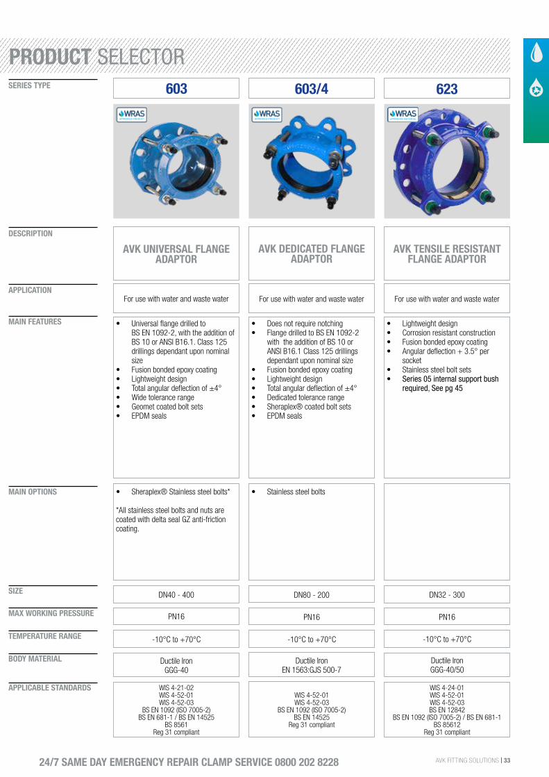
603
AVK UNIVERSAL FLANGE ADAPTOR
For use with water and waste water
• Universal flange drilled to BS EN 1092-2, with the addition of BS 10 or ANSI B16.1. Class 125 drillings dependant upon nominal size
• Fusion bonded epoxy coating• Lightweight design• Total angular deflection of ±4°• Wide tolerance range• Geomet coated bolt sets• EPDM seals
DN40 - 400
• Sheraplex® Stainless steel bolts*
*All stainless steel bolts and nuts are coated with delta seal GZ anti-friction coating.
PN16
-10°C to +70°C
Ductile Iron GGG-40
WIS 4-21-02WIS 4-52-01WIS 4-52-03
BS EN 1092 (ISO 7005-2)BS EN 681-1 / BS EN 14525
BS 8561Reg 31 compliant
603/4
AVK DEDICATED FLANGE ADAPTOR
For use with water and waste water
• Does not require notching• Flange drilled to BS EN 1092-2
with the addition of BS 10 or ANSI B16.1 Class 125 drillings dependant upon nominal size
• Fusion bonded epoxy coating• Lightweight design• Total angular deflection of ±4°• Dedicated tolerance range• Sheraplex® coated bolt sets• EPDM seals
DN80 - 200
• Stainless steel bolts
PN16
-10°C to +70°C
Ductile Iron EN 1563:GJS 500-7
WIS 4-52-01WIS 4-52-03
BS EN 1092 (ISO 7005-2)BS EN 14525
Reg 31 compliant
623
AVK TENSILE RESISTANT FLANGE ADAPTOR
For use with water and waste water
• Lightweight design• Corrosion resistant construction• Fusion bonded epoxy coating• Angular deflection + 3.5° per
socket• Stainless steel bolt sets• Series 05 internal support bush
required, See pg 45
DN32 - 300
PN16
-10°C to +70°C
Ductile IronGGG-40/50
WIS 4-24-01WIS 4-52-01WIS 4-52-03BS EN 12842
BS EN 1092 (ISO 7005-2) / BS EN 681-1BS 85612
Reg 31 compliant
PRODUCT SELECTOR
34 | AVK FITTING SOLUTIONS
SIZE
DESCRIPTION
SERIES TYPE
APPLICATION
MAIN FEATURES
MAIN OPTIONS
MAX WORKING PRESSURE
TEMPERATURE RANGE
BODY MATERIAL
APPLICABLE STANDARDS
24/7 SAME DAY EMERGENCY REPAIR CLAMP SERVICE 0800 202 8228
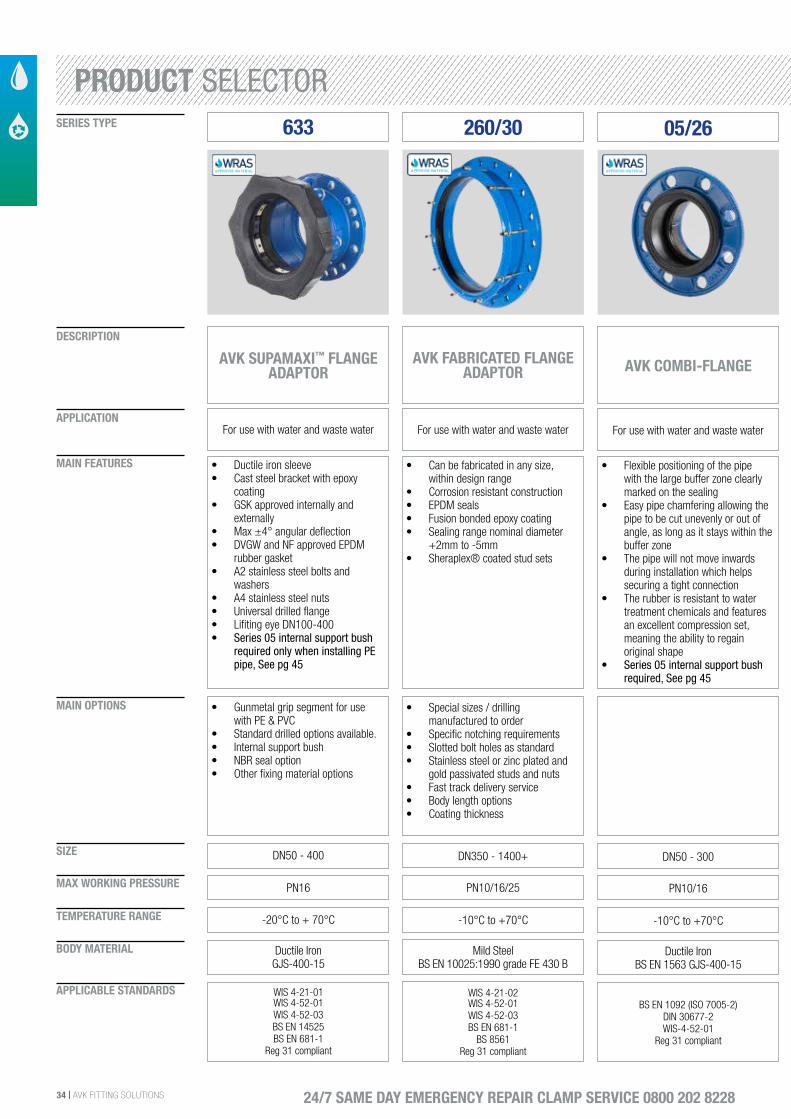
260/30
AVK FABRICATED FLANGE ADAPTOR
For use with water and waste water
• Can be fabricated in any size, within design range
• Corrosion resistant construction• EPDM seals• Fusion bonded epoxy coating• Sealing range nominal diameter
+2mm to -5mm• Sheraplex® coated stud sets
DN350 - 1400+
• Special sizes / drilling manufactured to order
• Specific notching requirements• Slotted bolt holes as standard• Stainless steel or zinc plated and
gold passivated studs and nuts • Fast track delivery service • Body length options• Coating thickness
PN10/16/25
-10°C to +70°C
Mild SteelBS EN 10025:1990 grade FE 430 B
WIS 4-21-02WIS 4-52-01WIS 4-52-03BS EN 681-1
BS 8561Reg 31 compliant
633
AVK SUPAMAXI™ FLANGE ADAPTOR
For use with water and waste water
• Ductile iron sleeve• Cast steel bracket with epoxy
coating• GSK approved internally and
externally• Max ±4° angular deflection• DVGW and NF approved EPDM
rubber gasket• A2 stainless steel bolts and
washers• A4 stainless steel nuts• Universal drilled flange• Lifiting eye DN100-400• Series 05 internal support bush
required only when installing PE pipe, See pg 45
DN50 - 400
• Gunmetal grip segment for use with PE & PVC
• Standard drilled options available.• Internal support bush• NBR seal option• Other fixing material options
PN16
-20°C to + 70°C
Ductile IronGJS-400-15
WIS 4-21-01WIS 4-52-01WIS 4-52-03BS EN 14525BS EN 681-1
Reg 31 compliant
05/26
AVK COMBI-FLANGE
For use with water and waste water
• Flexible positioning of the pipe with the large buffer zone clearly marked on the sealing
• Easy pipe chamfering allowing the pipe to be cut unevenly or out of angle, as long as it stays within the buffer zone
• The pipe will not move inwards during installation which helps securing a tight connection
• The rubber is resistant to water treatment chemicals and features an excellent compression set, meaning the ability to regain original shape
• Series 05 internal support bush required, See pg 45
DN50 - 300
PN10/16
-10°C to +70°C
Ductile Iron BS EN 1563 GJS-400-15
BS EN 1092 (ISO 7005-2) DIN 30677-2WIS-4-52-01
Reg 31 compliant
PRODUCT SELECTOR
AVK FITTING SOLUTIONS | 35 24/7 SAME DAY EMERGENCY REPAIR CLAMP SERVICE 0800 202 8228
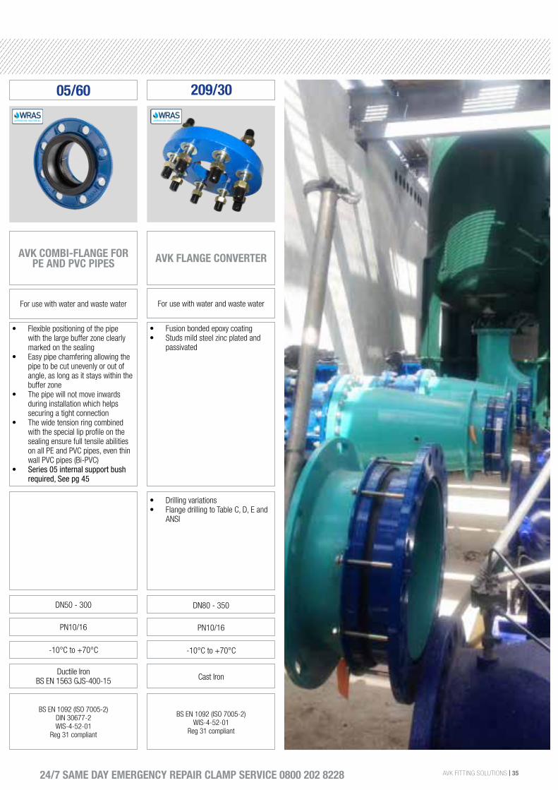
05/60
AVK COMBI-FLANGE FOR PE AND PVC PIPES
For use with water and waste water
• Flexible positioning of the pipe with the large buffer zone clearly marked on the sealing
• Easy pipe chamfering allowing the pipe to be cut unevenly or out of angle, as long as it stays within the buffer zone
• The pipe will not move inwards during installation which helps securing a tight connection
• The wide tension ring combined with the special lip profile on the sealing ensure full tensile abilities on all PE and PVC pipes, even thin wall PVC pipes (Bi-PVC)
• Series 05 internal support bush required, See pg 45
DN50 - 300
PN10/16
-10°C to +70°C
Ductile Iron BS EN 1563 GJS-400-15
BS EN 1092 (ISO 7005-2) DIN 30677-2WIS-4-52-01
Reg 31 compliant
• Drilling variations• Flange drilling to Table C, D, E and
ANSI
209/30
AVK FLANGE CONVERTER
For use with water and waste water
• Fusion bonded epoxy coating• Studs mild steel zinc plated and
passivated
DN80 - 350
PN10/16
-10°C to +70°C
Cast Iron
BS EN 1092 (ISO 7005-2) WIS-4-52-01
Reg 31 compliant
36 | AVK FITTING SOLUTIONS
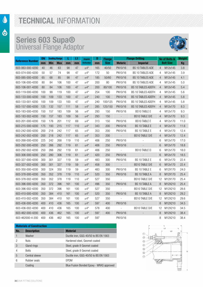
Reference NumberDN Sealing Range L L1 Angular
Deflection
D Flange Size
Flange Drilling No of Bolts & Bolt Size
Weightmm Min Max mm mm mm Meteric Imperial Kg
603-063-000-4200 40 46 63 98 47 ±4° 165 40/50 PN10/16 BS 10 TABLES ADE 4 M12x145 3.8
603-074-000-4200 50 57 74 98 47 ±4° 172 50 PN10/16 BS 10 TABLES ADE 4 M12x145 3.9
603-085-000-4200 65 68 85 98 47 ±4° 185 50/60 PN10/16 BS 10 TABLES ADE 4 M12x145 4.1
603-106-000-4200 80 84 106 100 47 ±4° 200 80 PN10/16 BS 10 TABLES ADE 4 M12x145 5.0
603-106-001-4200 80 84 106 100 47 ±4° 200 80/100 PN10/16 BS 10 TABLES ADEFH 4 M12x145 5.4
603-119-000-4200 100 99 119 100 47 ±4° 254 100 PN10/16 BS 10 TABLES ADEFH 4 M12x145 5.6
603-133-000-4200 100 109 133 100 47 ±4° 240 100 PN10/16 BS 10 TABLES ADEFH 4 M12x145 5.8
603-133-001-4200 100 109 133 100 47 ±4° 240 100/125 PN10/16 BS 10 TABLES ADEFH 4 M12x145 5.8
603-157-000-4200 125 132 157 111 58 ±4° 285 125/150 PN10/16 BS 10 TABLES ADEFH 4 M12x170 8.3
603-183-000-4200 150 157 183 109 56 ±4° 293 150 PN10/16 BS10 TABLE E 4 M12x170 9.3
603-183-002-4200 150 157 183 109 56 ±4° 293 150 - BS10 TABLE D/E 4 M12x170 9.3
603-201-000-4200 150 176 201 112 69 ±4° 313 150 PN10/16 BS10 TABLE E 4 M12x170 11.0
603-215-000-4200 175 193 215 117 110 ±4° 343 200 PN10/16 BS 10 TABLE E 4 M12x170 11.6
603-242-000-4200 200 218 242 117 65 ±4° 353 200 PN10/16 BS 10 TABLE E 4 M12x170 12.4
603-242-002-4200 200 218 242 117 65 ±4° 353 200 - BS10 TABLE D/E 4 M12x170 12.4
603-268-000-4200 225 242 268 119 110 ±4° 406 250 PN10/16 - 6 M12x170 17.0
603-292-000-4200 250 266 292 119 61 ±4° 406 250 PN10/16 - 6 M12x170 18.8
603-292-002-4200 250 266 292 119 61 ±4° 406 250 - BS10 TABLE D 6 M12x170 18.0
603-306-000-4200 250 280 306 119 61 ±4° 420 250 PN10/16 - 6 M12x170 18.5
603-327-000-4200 300 301 327 119 59 ±4° 483 300 PN10/16 BS 10 TABLE E 6 M12x170 22.4
603-327-002-4200 300 301 327 119 59 ±4° 458 300 - BS10 TABLE D/E 6 M12x170 22.4
603-350-000-4200 300 324 350 119 59 ±4° 483 300 PN10/16 BS 10 TABLE E 6 M12X170 24.0
603-378-000-4200 350 352 378 119 110 ±4° 520 350 PN10/16 BS 10 TABLE A 8 M12X170 25.4
603-378-002-4200 350 352 378 119 110 ±4° 527 350 - BS10 TABLE D/E 12 M12X170 25.4
603-396-000-4200 350 372 396 161 100 ±4° 496 350 PN10/16 BS 10 TABLE A 8 M12X210 25.4
603-396-002-4200 350 372 396 161 100 ±4° 527 350 - BS10 TABLE D/E 12 M12X210 28.6
603-410-000-4200 350 384 410 161 100 ±4° 520 350 PN10/16 BS 10 TABLE A 8 M12X210 29.2
603-410-002-4200 350 384 410 161 100 ±4° 527 350 - BS10 TABLE D/E 12 M12X210 29.6
603-436-000-4200 400 410 436 165 100 ±4° 597 400 PN10/16 - 8 M12X210 34.5
603-436-002-4200 400 410 436 165 100 ±4° 578 400 - BS10 TABLE D/E 12 M12X210 34.5
603-462-000-4200 400 436 462 165 100 ±4° 597 400 PN10/16 - 8 M12X210 38.4
603-462000-4-200 400 436 462 165 100 ±4° 597 PN10/16 8 M12X210 38.4
Materials of Construction
No. Description Material
1 Washer Ductile iron, GGG-40/50 to BS EN 1563
2 Nuts Hardened steel, Geomet coated
3 Gland rings Steel, grade 8 Geomet coated
4 Bolts Steel, grade 8 Geomet coated
5 Central sleeve Ductile iron, GGG-40/50 to BS EN 1563
6 Rubber seals EPDM
Coating Blue Fusion Bonded Epoxy - WRAS approved
The designs, materials and specifications shown are subject to change without notice. This is due to the continuous development of our product programme.
Version no. 76 - 1-26-2016 8:18
AVK SERIES 603 UNIVERSAL SUPA® FLANGE ADAPTORMild steel Sheraplex bolts/nuts, WRAS approved EPDM sealings
603/A4100
Flange DN Drilling 40/50 - 80 ISO 7005-2, ANSI B16 CL 125, BS 10 Table A, D and E 80/100 - 125/150 ISO 7005-2, ANSI B16 CL 125, BS 10 Table A, D, E, F and H 150 - 200 ISO 7005-2, ANSI B16 CL 125 and BS 10 Table E 250 ISO 7005-2 and ANSI B16 CL 125 300 ISO 7005-2, ANSI B16 CL 125 and BS 10 Table E 350 ISO 7005-2 and BS 10 Table A 400 ISO 7005-2 and ANSI B16 CL 125
Component List:
1. End cap Plastic 2. Washer Hot dip galvanized steel
3. Nut Mild steel, sheraplex 4. Bolt Mild steel, sheraplex
5. Bracket Ductile iron, EN-GJS-500-7(GGG-50) 6. Gasket EPDM
7. Adaptor flange Ductile iron, EN-GJS-500-7(GGG-50)
Components may be substituted with equivalent or higher class materials without prior notification.
Reference Nos. and Dimensions:
AVK ref. nosDNmm
Lmm
L1mm
L2mm
L3mm
D mm
Sealing Range mm
Theoretic.weight
kg
603-063-000-4100 40/50 159 47 145 98 165 46 - 63 3.8603-074-000-4100 50 159 47 145 98 172 57 - 74 3.9603-074-001-4100 50/60 159 47 145 98 185 57 - 74 4.1603-085-000-4100 50/60 159 47 145 98 185 68 - 85 4.2603-106-000-4100 80 159 47 145 100 200 84 - 106 5.0603-106-001-4100 80/100 159 47 145 100 200 84 - 106 5.9603-119-000-4100 100 159 47 145 100 254 99 - 119 5.6603-133-000-4100 100 159 47 145 101 240 109 - 133 5.8603-133-001-4100 100/125 159 47 145 101 240 109 - 133 5.8603-157-000-4100 125/150 184 58 170 111 285 132 - 157 8.3603-183-000-4100 150 184 56 170 109 293 157 - 183 9.3603-183-002-4100 150 184 56 170 109 293 157 - 183 9.3603-201-000-4100 150 184 69 170 112 313 176 - 201 11603-215-000-4100 200 182 110 170 117 343 193 - 215 12603-242-000-4100 200 182 65 170 117 353 218 - 242 12603-242-002-4100 200 182 65 170 117 353 218 - 242 12603-268-000-4100 250 182 110 170 119 406 242 - 268 17603-292-000-4100 250 182 61 170 119 406 266 - 292 19603-292-002-4100 250 182 61 170 119 406 266 - 292 18603-306-000-4100 250 182 61 170 119 420 280 - 306 19
3/33/32/3
Series 603 Supa®Universal Flange Adaptor
TECHNICAL INFORMATION
AVK FITTING SOLUTIONS | 37
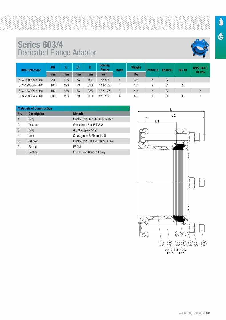
Materials of Construction
No. Description Material
1 Body Ductile iron EN 1563:GJS 500-7
2 Washers Galvanised. SteelST37.2
3 Bolts 4.6 Sheraplex M12
4 Nuts Steel, grade 8, Sheraplex®
5 Bracket Ductile iron. EN 1563:GJS 500-7
6 Gasket EPDM
Coating Blue Fusion Bonded Epoxy
AVK ReferenceDN L L1 D
Sealing Range Bolts
WeightPN10/16 EN1092 BS 10
ANSI 161.1 CI 125
mm mm mm mm mm Kg
603-099004-4-100 80 126 73 192 88-99 4 3.2 X X
603-123004-4-100 100 126 73 216 114-123 4 3.6 X X X
603-178004-4-100 150 126 73 285 168-178 4 4.2 X X X
603-233004-4-100 200 126 73 339 219-233 4 6.2 X X X X
The designs, materials and specifications shown are subject to change without notice. This is due to the continuous development of our product programme.
Version no. 29 - 1-26-2016 8:32
AVK SERIES 603 UNIVERSAL SUPA® FLANGE ADAPTORMild steel Sheraplex bolts/nuts, WRAS approved EPDM sealings, UK Version
603/A41004
D
C
C
Component List:
1. Adaptor flange Ductile iron, EN-GJS-500-7(GGG-50) 2. Bolt Mild steel, sheraplex
3. Bracket Ductile iron, EN-GJS-500-7(GGG-50) 4. Gasket EPDM
5. Washer Hot dip galvanized steel 6. Nut Mild steel, sheraplex
7. End cap Plastic
Components may be substituted with equivalent or higher class materials without prior notification.
Reference Nos. and Dimensions:
AVK ref. nosDNmm
Lmm
L1mm
L2mm
D mm
Sealing Range mm
Theoretic.weight
kg
603-099-004-4100 80 126 73 110 192 88 - 99 3.2603-123-004-4100 100 126 73 110 216 114 - 123 3.6603-178-004-4100 150 126 73 110 285 168 - 178 4.2603-233-004-4100 200 126 73 110 339 219 - 233 6.2
PB/12/2
Series 603/4Dedicated Flange Adaptor
38 | AVK FITTING SOLUTIONS
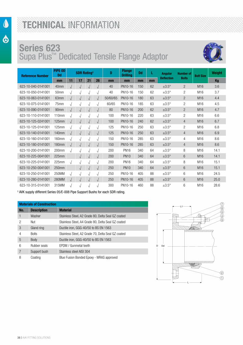
Materials of Construction
No. Description Material
1 Washer Stainless Steel, A2 Grade 80, Delta Seal GZ coated
2 Nut Stainless Steel, A4 Grade 80, Delta Seal GZ coated
3 Gland ring Ductile iron, GGG-40/50 to BS EN 1563
4 Bolts Stainless Steel, A2 Grade 70, Delta Seal GZ coated
5 Body Ductile iron, GGG-40/50 to BS EN 1563
6 Rubber seals EPDM / Gunmetal teeth
7 Support bush Stainless steel AISI 304
8 Coating Blue Fusion Bonded Epoxy - WRAS approved
The designs, materials and specifications shown are subject to change without notice.This is due to the continuous development of our product programme.
Version no. 59 - 5-27-2014 9:00
AVK SUPA PLUS™ FLANGE ADAPTOR, PN10/16Tensile, for PE and PVC pipes
623/10001
L1
D
7
6
5
4
3
2
1
L
Dd
Component List:
1. Adaptor flange Ductile iron GJS-500-7 (GGG-50) 2. Combined gasket NF approved EPDM rubber/RG5 bronze3. Bracket Ductile iron GJS-500-7 (GGG-50) 4. Cap Plastic5. Nut Acid resistant stainless steel A4 6. Washer Stainless steel A27. Rectangular bolt Stainless steel A2
Components may be substituted with equivalent or higher class materials without prior notification.
Reference Nos. and Dimensions:
AVK ref. nosDNmm
Ddmm
Flangedrilling
D mm
Lmm
L1mm
Theoreticalweight kg
623-10-040-0141 (1) 40 40 PN10/16 150 122 62 3.6623-10-050-0141 (1) 40 50 PN10/16 150 122 62 3.7623-10-063-0141 (1) 50 63 PN10/16 180 123 63 4.4623-10-075-0141 (1) 65 75 PN10/16 185 123 63 4.5623-10-090-0141 (1) 80 90 PN10/16 200 122 62 4.7623-10-110-0141 (1) 100 110 PN10/16 220 123 63 6.6623-10-125-0141 (1) 125 125 PN10/16 250 125 63 6.8623-10-125-0241 (1) 100 125 PN10/16 240 125 62 6.7623-10-140-0141 (1) 125 140 PN10/16 250 125 63 6.9623-10-160-0141 (1) 150 160 PN10/16 285 125 63 8.6623-10-180-0141 (1) 150 180 PN10/16 285 125 63 8.6623-10-200-0041 200 200 PN10 340 126 64 14623-10-200-0141 200 200 PN16 340 126 64 14623-10-225-0041 200 225 PN10 340 141 64 15623-10-225-0141 200 225 PN16 340 141 64 15623-10-250-0141 (1) 250 250 PN10/16 405 179 88 25623-10-250-0241 (1) 200 250 PN10/16 405 179 88 25623-10-280-0141 (1) 250 280 PN10/16 405 179 88 25623-10-315-0141 (1) 300 315 PN10/16 460 179 88 29623-10-315-0241 (1) 250 315 PN10/16 460 179 88 29(1) 10/16 = Universal drilling
Reference NumberPIPE OD
DdSDR Rating¹ D
Flange Drilling
Dd L Angular Deflection
Number of Bolts
Bolt SizeWeight
mm 11 17 21 26 mm mm mm mm Kg
623-10-040-0141001 40mm √ √ √ √ 40 PN10-16 150 62 ±3.5° 2 M16 3.6
623-10-050-0141001 50mm √ √ √ √ 40 PN10-16 150 62 ±3.5° 2 M16 3.7
623-10-063-0141001 63mm √ √ √ √ 50/60/65 PN10-16 180 63 ±3.5° 2 M16 4.4
623-10-075-0141001 75mm √ √ √ √ 60/65 PN10-16 185 63 ±3.5° 2 M16 4.5
623-10-090-0141001 90mm √ √ √ √ 80 PN10-16 200 62 ±3.5° 2 M16 4.7
623-10-110-0141001 110mm √ √ √ √ 100 PN10-16 220 63 ±3.5° 2 M16 6.6
623-10-125-0241001 125mm √ √ √ √ 100 PN10-16 240 62 ±3.5° 4 M16 6.7
623-10-125-0141001 125mm √ √ √ √ 125 PN10-16 250 63 ±3.5° 2 M16 6.8
623-10-140-0141001 140mm √ √ √ √ 125 PN10-16 250 63 ±3.5° 4 M16 6.9
623-10-160-0141001 160mm √ √ √ √ 150 PN10-16 285 63 ±3.5° 4 M16 8.6
623-10-180-0141001 180mm √ √ √ √ 150 PN10-16 285 63 ±3.5° 4 M16 8.6
623-10-200-0141001 200mm √ √ √ √ 200 PN16 340 64 ±3.5° 8 M16 14.1
623-10-225-0041001 225mm √ √ √ 200 PN10 340 64 ±3.5° 6 M16 14.1
623-10-225-0141001 225mm √ √ √ √ 200 PN16 340 64 ±3.5° 8 M16 15.1
623-10-250-0041001 250mm √ √ √ 250 PN10 340 64 ±3.5° 6 M16 15.1
623-10-250-0141001 250MM √ √ √ √ 250 PN10-16 405 88 ±3.5° 6 M16 24.5
623-10-280-0141001 280MM √ √ √ √ 250 PN10-16 405 88 ±3.5° 6 M16 25.0
623-10-315-0141001 315MM √ √ √ √ 300 PN10-16 460 88 ±3.5° 6 M16 28.6
¹ AVK supply different Series 05/E-008 Pipe Support Bushs for each SDR rating.
Series 623Supa Plus™ Dedicated Tensile Flange Adaptor
TECHNICAL INFORMATION
AVK FITTING SOLUTIONS | 39
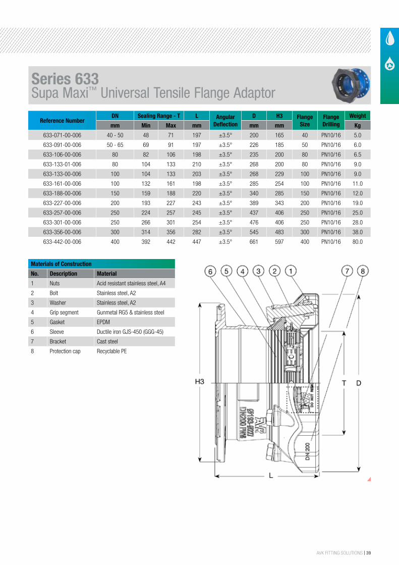
Reference NumberDN Sealing Range - T L Angular
DeflectionD H3 Flange
SizeFlange Drilling
Weight
mm Min Max mm mm mm Kg
633-071-00-006 40 - 50 48 71 197 ±3.5° 200 165 40 PN10/16 5.0
633-091-00-006 50 - 65 69 91 197 ±3.5° 226 185 50 PN10/16 6.0
633-106-00-006 80 82 106 198 ±3.5° 235 200 80 PN10/16 6.5
633-133-01-006 80 104 133 210 ±3.5° 268 200 80 PN10/16 9.0
633-133-00-006 100 104 133 203 ±3.5° 268 229 100 PN10/16 9.0
633-161-00-006 100 132 161 198 ±3.5° 285 254 100 PN10/16 11.0
633-188-00-006 150 159 188 220 ±3.5° 340 285 150 PN10/16 12.0
633-227-00-006 200 193 227 243 ±3.5° 389 343 200 PN10/16 19.0
633-257-00-006 250 224 257 245 ±3.5° 437 406 250 PN10/16 25.0
633-301-00-006 250 266 301 254 ±3.5° 476 406 250 PN10/16 28.0
633-356-00-006 300 314 356 282 ±3.5° 545 483 300 PN10/16 38.0
633-442-00-006 400 392 442 447 ±3.5° 661 597 400 PN10/16 80.0
Materials of Construction
No. Description Material
1 Nuts Acid resistant stainless steel, A4
2 Bolt Stainless steel, A2
3 Washer Stainless steel, A2
4 Grip segment Gunmetal RG5 & stainless steel
5 Gasket EPDM
6 Sleeve Ductile iron GJS-450 (GGG-45)
7 Bracket Cast steel
8 Protection cap Recyclable PE
Universal and tensile, A2 bolts, EPDM sealing
AVK SUPA MAXI™ FLANGE ADAPTOR, PN 16 633/00-001
Component list:
1
2
3
4
1.
2.
3.
4.
Nut
Bolt
Washer
Grip segment
Stainless steel A4
Stainless steel A2
Stainless steel A2
Stainless steel / bronze CC491K
5
6
7
8
5.
6.
7.
8.
Gasket
Sleeve
Bracket
Protection cap
EPDM rubber
Ductile iron GJS-450-10
Cast steel
PE
Components may be substituted with equivalent or higher class materials without prior notification.
Reference nos. and dimensions:
AVK ref. no. DN
mm
Product
PN Class
T
mm
L
mm
D
mm
H3
mm
Theoretical
weight / kg
633-071-00-006
633-091-00-006
633-106-00-006
633-133-00-006
633-133-01-006
633-161-00-006
633-161-01-006
633-188-00-006
633-227-00-006
633-257-00-006
633-257-01-006
633-301-00-006
633-356-00-006
40-50
50-65
80
100
80
100
150
150
200
250
200
250
300
PN16
PN16
PN16
PN16
PN16
PN16
PN16
PN16
PN16
PN16
PN16
PN16
PN16
48 - 71
69 - 91
82 - 106
104 - 133
104 - 133
132 - 161
132 - 161
159 - 188
193 - 227
224 - 257
224 - 257
266 - 301
314 - 356
197
197
198
203
210
198
198
220
243
245
245
254
282
200
226
235
268
268
285
285
340
389
437
437
476
545
165
185
200
229
200
254
254
285
343
406
406
406
483
5.0
6.0
6.5
9.0
9.0
11
11
12
19
25
25
28
38
Row to make sure table is never blank
2/231-jul-2017 13:01js -
The designs, materials and specifications shown are subject to change without notice due to the continuous development of our product range.
COPYRIGHT©AVK GROUP 2017
DRAFT
Series 633Supa Maxi™ Universal Tensile Flange Adaptor
40 | AVK FITTING SOLUTIONS
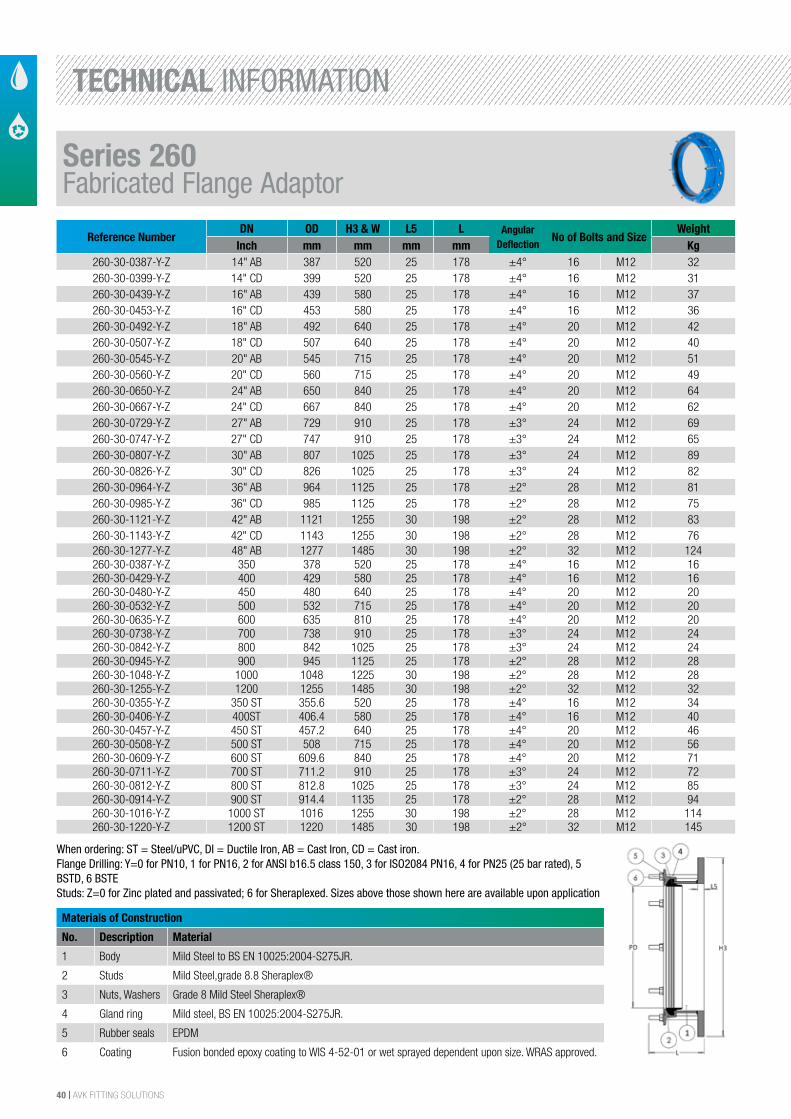
Reference NumberDN OD H3 & W L5 L Angular
DeflectionNo of Bolts and Size
WeightInch mm mm mm mm Kg
260-30-0387-Y-Z 14" AB 387 520 25 178 ±4° 16 M12 32260-30-0399-Y-Z 14" CD 399 520 25 178 ±4° 16 M12 31260-30-0439-Y-Z 16" AB 439 580 25 178 ±4° 16 M12 37260-30-0453-Y-Z 16" CD 453 580 25 178 ±4° 16 M12 36260-30-0492-Y-Z 18" AB 492 640 25 178 ±4° 20 M12 42260-30-0507-Y-Z 18" CD 507 640 25 178 ±4° 20 M12 40260-30-0545-Y-Z 20" AB 545 715 25 178 ±4° 20 M12 51260-30-0560-Y-Z 20" CD 560 715 25 178 ±4° 20 M12 49260-30-0650-Y-Z 24" AB 650 840 25 178 ±4° 20 M12 64260-30-0667-Y-Z 24" CD 667 840 25 178 ±4° 20 M12 62260-30-0729-Y-Z 27" AB 729 910 25 178 ±3° 24 M12 69260-30-0747-Y-Z 27" CD 747 910 25 178 ±3° 24 M12 65260-30-0807-Y-Z 30" AB 807 1025 25 178 ±3° 24 M12 89260-30-0826-Y-Z 30" CD 826 1025 25 178 ±3° 24 M12 82260-30-0964-Y-Z 36" AB 964 1125 25 178 ±2° 28 M12 81260-30-0985-Y-Z 36" CD 985 1125 25 178 ±2° 28 M12 75260-30-1121-Y-Z 42" AB 1121 1255 30 198 ±2° 28 M12 83260-30-1143-Y-Z 42" CD 1143 1255 30 198 ±2° 28 M12 76260-30-1277-Y-Z 48" AB 1277 1485 30 198 ±2° 32 M12 124260-30-0387-Y-Z 350 378 520 25 178 ±4° 16 M12 16260-30-0429-Y-Z 400 429 580 25 178 ±4° 16 M12 16260-30-0480-Y-Z 450 480 640 25 178 ±4° 20 M12 20260-30-0532-Y-Z 500 532 715 25 178 ±4° 20 M12 20260-30-0635-Y-Z 600 635 810 25 178 ±4° 20 M12 20260-30-0738-Y-Z 700 738 910 25 178 ±3° 24 M12 24260-30-0842-Y-Z 800 842 1025 25 178 ±3° 24 M12 24260-30-0945-Y-Z 900 945 1125 25 178 ±2° 28 M12 28260-30-1048-Y-Z 1000 1048 1225 30 198 ±2° 28 M12 28260-30-1255-Y-Z 1200 1255 1485 30 198 ±2° 32 M12 32260-30-0355-Y-Z 350 ST 355.6 520 25 178 ±4° 16 M12 34260-30-0406-Y-Z 400ST 406.4 580 25 178 ±4° 16 M12 40260-30-0457-Y-Z 450 ST 457.2 640 25 178 ±4° 20 M12 46260-30-0508-Y-Z 500 ST 508 715 25 178 ±4° 20 M12 56260-30-0609-Y-Z 600 ST 609.6 840 25 178 ±4° 20 M12 71260-30-0711-Y-Z 700 ST 711.2 910 25 178 ±3° 24 M12 72260-30-0812-Y-Z 800 ST 812.8 1025 25 178 ±3° 24 M12 85260-30-0914-Y-Z 900 ST 914.4 1135 25 178 ±2° 28 M12 94260-30-1016-Y-Z 1000 ST 1016 1255 30 198 ±2° 28 M12 114260-30-1220-Y-Z 1200 ST 1220 1485 30 198 ±2° 32 M12 145
Materials of Construction
No. Description Material
1 Body Mild Steel to BS EN 10025:2004-S275JR.
2 Studs Mild Steel,grade 8.8 Sheraplex®
3 Nuts, Washers Grade 8 Mild Steel Sheraplex®
4 Gland ring Mild steel, BS EN 10025:2004-S275JR.
5 Rubber seals EPDM
6 Coating Fusion bonded epoxy coating to WIS 4-52-01 or wet sprayed dependent upon size. WRAS approved.
When ordering: ST = Steel/uPVC, DI = Ductile Iron, AB = Cast Iron, CD = Cast iron.Flange Drilling: Y=0 for PN10, 1 for PN16, 2 for ANSI b16.5 class 150, 3 for ISO2084 PN16, 4 for PN25 (25 bar rated), 5 BSTD, 6 BSTEStuds: Z=0 for Zinc plated and passivated; 6 for Sheraplexed. Sizes above those shown here are available upon application
Series 260Fabricated Flange Adaptor
TECHNICAL INFORMATION
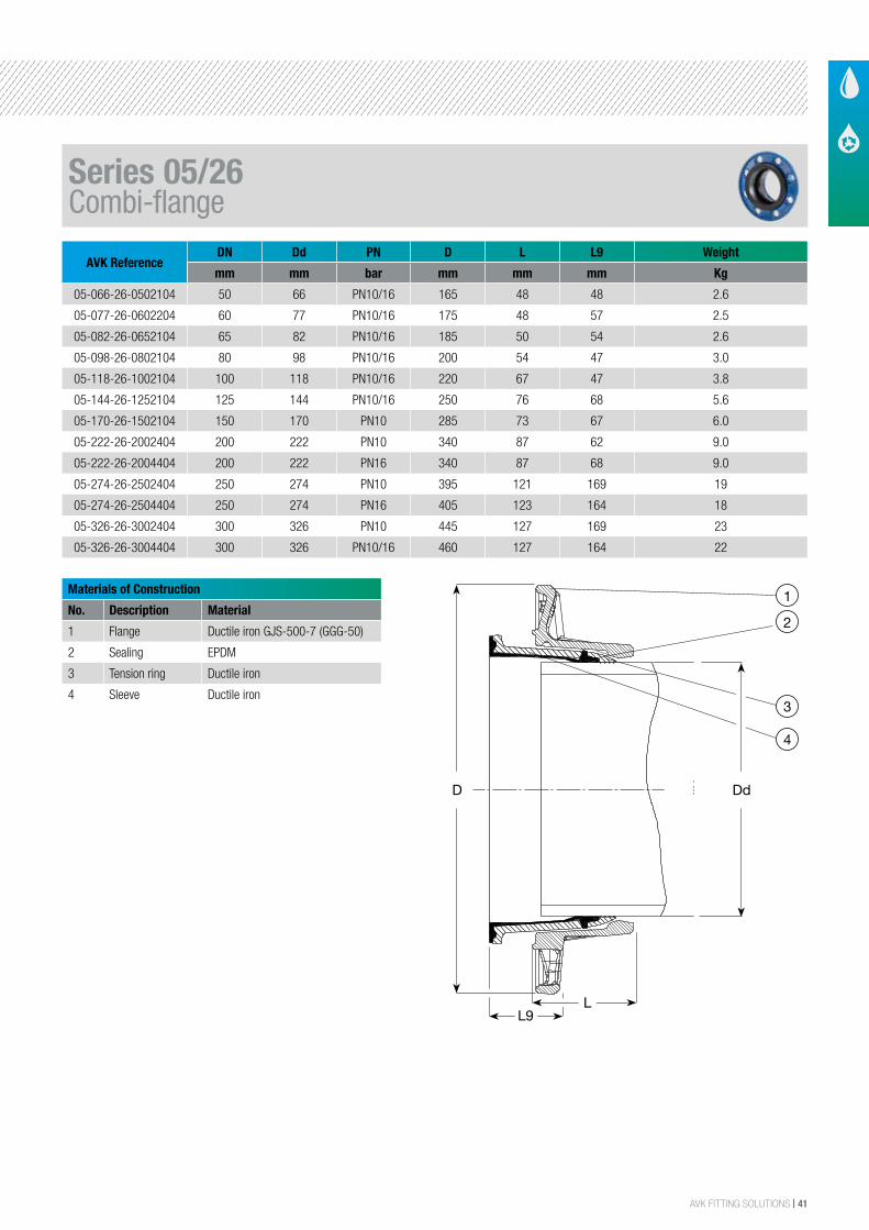
AVK FITTING SOLUTIONS | 41
AVK ReferenceDN Dd PN D L L9 Weight
mm mm bar mm mm mm Kg
05-066-26-0502104 50 66 PN10/16 165 48 48 2.6
05-077-26-0602204 60 77 PN10/16 175 48 57 2.5
05-082-26-0652104 65 82 PN10/16 185 50 54 2.6
05-098-26-0802104 80 98 PN10/16 200 54 47 3.0
05-118-26-1002104 100 118 PN10/16 220 67 47 3.8
05-144-26-1252104 125 144 PN10/16 250 76 68 5.6
05-170-26-1502104 150 170 PN10 285 73 67 6.0
05-222-26-2002404 200 222 PN10 340 87 62 9.0
05-222-26-2004404 200 222 PN16 340 87 68 9.0
05-274-26-2502404 250 274 PN10 395 121 169 19
05-274-26-2504404 250 274 PN16 405 123 164 18
05-326-26-3002404 300 326 PN10 445 127 169 23
05-326-26-3004404 300 326 PN10/16 460 127 164 22
Materials of Construction
No. Description Material
1 Flange Ductile iron GJS-500-7 (GGG-50)
2 Sealing EPDM
3 Tension ring Ductile iron
4 Sleeve Ductile iron
The designs, materials and specifications shown are subject to change without notice. This is due to the continuous development of our product programme.
Version no. 46 - 9-3-2014 1:06
AVK COMBI-FLANGE FOR D.I. PIPES, PN 10/16Tensile, EPDM sealing
05/26001
D
1
2
3
Dd
L9L
Non Tensile
D
1
2
3
L9L
Tensile
4
Dd
Component List:
1. Flange Ductile iron GJS-500-7 (GGG-50) 2. Sealing EPDM rubber
3. Tension ring Ductile iron 4. Sleeve Ductile iron
Components may be substituted with equivalent or higher class materials without prior notification.
Reference Nos. and Dimensions:
AVK ref. nosDNmm
Ddmm
Flangedrilling
D mm
Lmm
L9mm
Theoreticalweight kg
05-066-26-0502104 50 66 PN10/16 165 48 48 2.605-077-26-0602204 60 77 PN10/16 175 48 57 2.505-082-26-0652104 65 82 PN10/16 185 50 54 2.605-098-26-0802104 80 98 PN10/16 200 54 47 3.005-118-26-1002104 100 118 PN10/16 220 67 47 3.805-144-26-1252104 125 144 PN10/16 250 76 68 5.605-170-26-1502104 150 170 PN10 285 73 67 6.005-222-26-2002404 200 222 PN10 340 87 62 9.005-222-26-2004404 200 222 PN16 340 87 68 9.005-274-26-2502404 250 274 PN10 395 121 169 1905-274-26-2504404 250 274 PN16 405 123 164 1805-326-26-3002404 300 326 PN10 445 127 169 2305-326-26-3004404 300 326 PN10/16 460 127 164 22
PB/12/2
Series 05/26Combi-flange
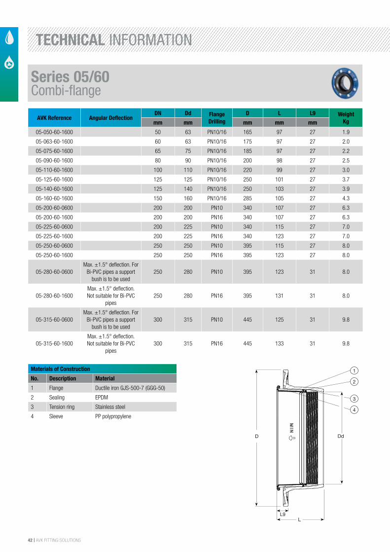
42 | AVK FITTING SOLUTIONS
AVK Reference Angular DeflectionDN Dd Flange
Drilling D L L9 Weight
Kgmm mm mm mm mm
05-050-60-1600 50 63 PN10/16 165 97 27 1.9
05-063-60-1600 60 63 PN10/16 175 97 27 2.0
05-075-60-1600 65 75 PN10/16 185 97 27 2.2
05-090-60-1600 80 90 PN10/16 200 98 27 2.5
05-110-60-1600 100 110 PN10/16 220 99 27 3.0
05-125-60-1600 125 125 PN10/16 250 101 27 3.7
05-140-60-1600 125 140 PN10/16 250 103 27 3.9
05-160-60-1600 150 160 PN10/16 285 105 27 4.3
05-200-60-0600 200 200 PN10 340 107 27 6.3
05-200-60-1600 200 200 PN16 340 107 27 6.3
05-225-60-0600 200 225 PN10 340 115 27 7.0
05-225-60-1600 200 225 PN16 340 123 27 7.0
05-250-60-0600 250 250 PN10 395 115 27 8.0
05-250-60-1600 250 250 PN16 395 123 27 8.0
05-280-60-0600Max. ±1.5° deflection. For
Bi-PVC pipes a support bush is to be used
250 280 PN10 395 123 31 8.0
05-280-60-1600Max. ±1.5° deflection. Not suitable for Bi-PVC
pipes250 280 PN16 395 131 31 8.0
05-315-60-0600Max. ±1.5° deflection. For
Bi-PVC pipes a support bush is to be used
300 315 PN10 445 125 31 9.8
05-315-60-1600Max. ±1.5° deflection. Not suitable for Bi-PVC
pipes300 315 PN16 445 133 31 9.8
Materials of Construction
No. Description Material
1 Flange Ductile iron GJS-500-7 (GGG-50)
2 Sealing EPDM
3 Tension ring Stainless steel
4 Sleeve PP polypropylene
The designs, materials and specifications shown are subject to change without notice. This is due to the continuous development of our product programme.
Version no. 50 - 9-3-2014 12:56
AVK COMBI-FLANGE FOR PE AND PVC PIPES, PN 10/16Tensile, EPDM sealing
05/60001
D
1
2
L9L
3
4
Dd
Component List:
1. Flange Ductile iron GJS-500-7 (GGG-50) 2. Sealing EPDM rubber
3. Tension ring Stainless steel 4. Sleeve PP polypropylene
Components may be substituted with equivalent or higher class materials without prior notification.
Reference Nos. and Dimensions:
AVK ref. nosDNmm
Ddmm
Flangedrilling
D mm
Lmm
L9mm
Theoreticalweight kg
05-050-60-1600 50 63 PN10/16 165 97 27 1.905-063-60-1600 60 63 PN10/16 175 97 27 2.005-075-60-1600 65 75 PN10/16 185 97 27 2.205-090-60-1600 80 90 PN10/16 200 98 27 2.505-110-60-1600 100 110 PN10/16 220 99 27 3.005-125-60-1600 125 125 PN10/16 250 101 27 3.705-140-60-1600 125 140 PN10/16 250 103 27 3.905-160-60-1600 150 160 PN10/16 285 105 27 4.305-200-60-0600 200 200 PN10 340 107 27 6.305-200-60-1600 200 200 PN16 340 107 27 6.305-225-60-0600 200 225 PN10 340 115 27 7.005-225-60-1600 200 225 PN16 340 123 27 7.005-250-60-0600 250 250 PN10 395 115 27 8.005-250-60-1600 250 250 PN16 395 123 27 8.005-280-60-0600 (1) 250 280 PN10 395 123 31 8.005-280-60-1600 (2) 250 280 PN16 395 131 31 8.005-315-60-0600 (1) 300 315 PN10 445 125 31 9.805-315-60-1600 (2) 300 315 PN16 445 133 31 9.8(1) Max. ±1.5° deflection. For Bi-PVC pipes a support bush is to be used(2) Max. ±1.5° deflection. Not suitable for Bi-PVC pipes
PB/12/2
Series 05/60Combi-flange
TECHNICAL INFORMATION
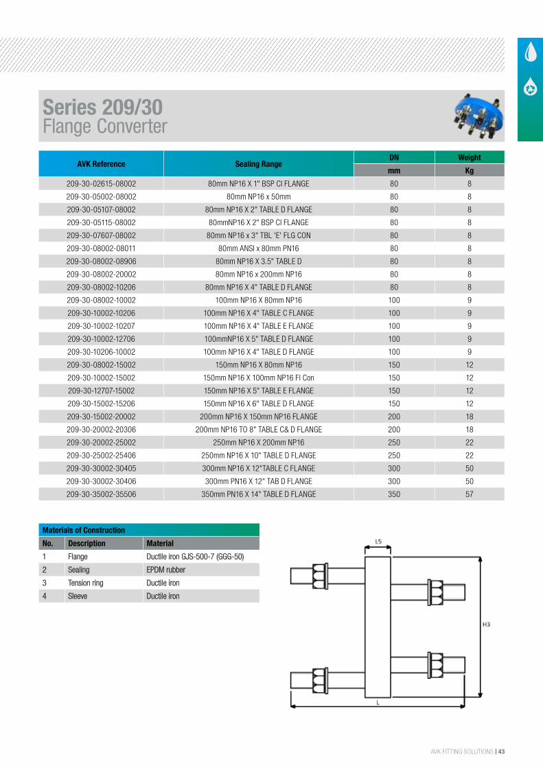
AVK FITTING SOLUTIONS | 43
AVK Reference Sealing RangeDN Weight
mm Kg
209-30-02615-08002 80mm NP16 X 1" BSP CI FLANGE 80 8
209-30-05002-08002 80mm NP16 x 50mm 80 8
209-30-05107-08002 80mm NP16 X 2" TABLE D FLANGE 80 8
209-30-05115-08002 80mmNP16 X 2" BSP CI FLANGE 80 8
209-30-07607-08002 80mm NP16 x 3" TBL 'E' FLG CON 80 8
209-30-08002-08011 80mm ANSI x 80mm PN16 80 8
209-30-08002-08906 80mm NP16 X 3.5" TABLE D 80 8
209-30-08002-20002 80mm NP16 x 200mm NP16 80 8
209-30-08002-10206 80mm NP16 X 4" TABLE D FLANGE 80 8
209-30-08002-10002 100mm NP16 X 80mm NP16 100 9
209-30-10002-10206 100mm NP16 X 4" TABLE C FLANGE 100 9
209-30-10002-10207 100mm NP16 X 4" TABLE E FLANGE 100 9
209-30-10002-12706 100mmNP16 X 5" TABLE D FLANGE 100 9
209-30-10206-10002 100mm NP16 X 4" TABLE D FLANGE 100 9
209-30-08002-15002 150mm NP16 X 80mm NP16 150 12
209-30-10002-15002 150mm NP16 X 100mm NP16 Fl Con 150 12
209-30-12707-15002 150mm NP16 X 5" TABLE E FLANGE 150 12
209-30-15002-15206 150mm NP16 X 6" TABLE D FLANGE 150 12
209-30-15002-20002 200mm NP16 X 150mm NP16 FLANGE 200 18
209-30-20002-20306 200mm NP16 TO 8" TABLE C& D FLANGE 200 18
209-30-20002-25002 250mm NP16 X 200mm NP16 250 22
209-30-25002-25406 250mm NP16 X 10" TABLE D FLANGE 250 22
209-30-30002-30405 300mm NP16 X 12"TABLE C FLANGE 300 50
209-30-30002-30406 300mm PN16 X 12" TAB D FLANGE 300 50
209-30-35002-35506 350mm PN16 X 14" TABLE D FLANGE 350 57
Materials of Construction
No. Description Material
1 Flange Ductile iron GJS-500-7 (GGG-50)
2 Sealing EPDM rubber
3 Tension ring Ductile iron
4 Sleeve Ductile iron
Series 209/30Flange Converter
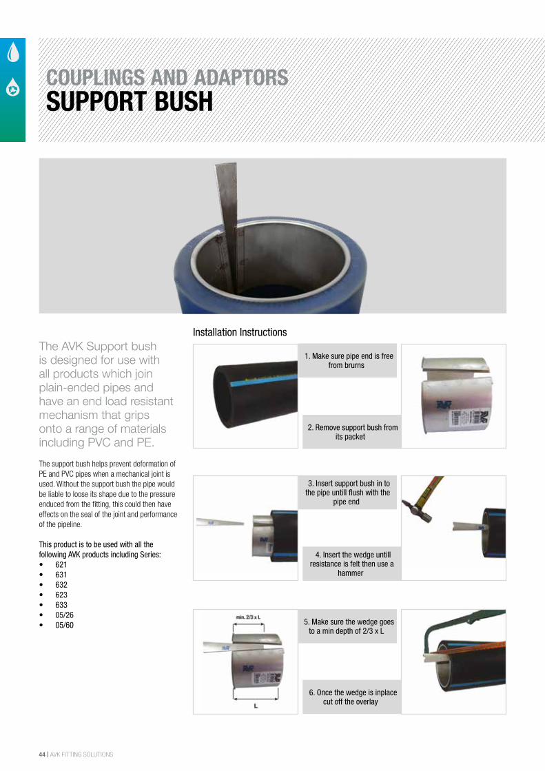
44 | AVK FITTING SOLUTIONS
COUPLINGS AND ADAPTORSSUPPORT BUSH
The AVK Support bush is designed for use with all products which join plain-ended pipes and have an end load resistant mechanism that grips onto a range of materials including PVC and PE.
The support bush helps prevent deformation of PE and PVC pipes when a mechanical joint is used. Without the support bush the pipe would be liable to loose its shape due to the pressure enduced from the fitting, this could then have effects on the seal of the joint and performance of the pipeline.
This product is to be used with all the following AVK products including Series:• 621• 631• 632• 623• 633• 05/26• 05/60
1. Make sure pipe end is free from brurns
2. Remove support bush from its packet
3. Insert support bush in to the pipe untill flush with the
pipe end
4. Insert the wedge untill resistance is felt then use a
hammer
5. Make sure the wedge goes to a min depth of 2/3 x L
6. Once the wedge is inplace cut off the overlay
Installation Instructions
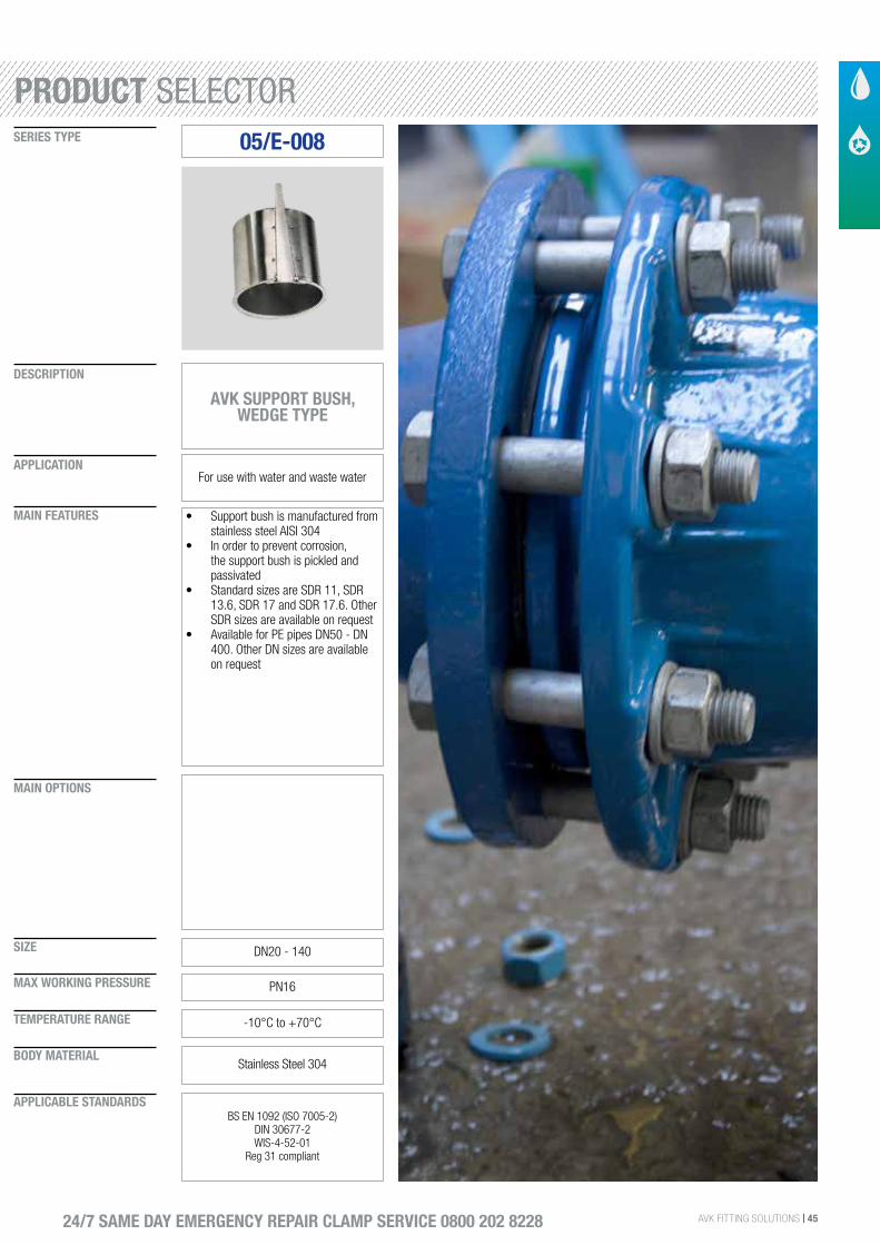
AVK FITTING SOLUTIONS | 45
SIZE
DESCRIPTION
SERIES TYPE
APPLICATION
MAIN FEATURES
MAIN OPTIONS
MAX WORKING PRESSURE
TEMPERATURE RANGE
BODY MATERIAL
APPLICABLE STANDARDS
24/7 SAME DAY EMERGENCY REPAIR CLAMP SERVICE 0800 202 8228
05/E-008
AVK SUPPORT BUSH, WEDGE TYPE
For use with water and waste water
• Support bush is manufactured from stainless steel AISI 304
• In order to prevent corrosion, the support bush is pickled and passivated
• Standard sizes are SDR 11, SDR 13.6, SDR 17 and SDR 17.6. Other SDR sizes are available on request
• Available for PE pipes DN50 - DN 400. Other DN sizes are available on request
DN20 - 140
PN16
-10°C to +70°C
Stainless Steel 304
BS EN 1092 (ISO 7005-2) DIN 30677-2WIS-4-52-01
Reg 31 compliant
PRODUCT SELECTOR
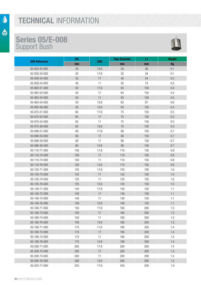
46 | AVK FITTING SOLUTIONS
AVK ReferenceDN
SDRPipe Diameter L1 Weight
mm mm mm Kg
05-025-54-002 20 13.6 25 36 0.1
05-032-54-002 25 17.6 32 44 0.1
05-040-54-002 32 17 40 54 0.2
05-050-54-002 40 11 50 74 0.3
05-063-51-000 50 17.6 63 150 0.4
05-063-53-000 50 17 63 150 0.4
05-063-54-000 50 11 63 150 0.4
05-063-54-002 50 13.6 63 87 0.6
05-063-56-000 50 13.6 63 150 0.4
05-075-51-000 65 17.6 75 150 0.5
05-075-53-000 65 17 75 150 0.5
05-075-54-000 65 11 75 150 0.5
05-075-56-000 65 13.6 75 150 0.5
05-090-51-000 80 17.6 90 150 0.7
05-090-53-000 80 17 90 150 0.7
05-090-54-000 80 11 90 150 0.7
05-090-56-000 80 13.6 90 150 0.7
05-110-71-000 100 17.6 110 150 0.8
05-110-73-000 100 17 110 150 0.8
05-110-74-000 100 11 110 150 0.8
05-110-76-000 100 13.6 110 150 0.8
05-125-71-000 125 17.6 125 150 1.0
05-125-73-000 125 17 125 150 1.0
05-125-74-000 125 11 125 150 1.0
05-125-76-000 125 13.6 125 150 1.0
05-140-71-000 140 17.6 140 150 1.1
05-140-73-000 140 17 140 150 1.1
05-140-74-000 140 11 140 150 1.1
05-140-76-000 140 13.6 140 150 1.1
05-160-71-000 150 17.6 160 200 1.3
05-160-73-000 150 17 160 200 1.3
05-160-74-000 150 11 160 200 1.3
05-160-76-000 150 13.6 160 200 1.3
05-180-71-000 175 17,6 180 200 1.4
05-180-73-000 175 17 180 200 1.4
05-180-74-000 175 11 180 200 1.4
05-180-76-000 175 13.6 180 200 1.4
05-200-71-000 200 17.6 200 200 1.4
05-200-73-000 200 17 200 200 1.4
05-200-74-000 200 11 200 200 1.4
05-200-76-000 200 13.6 200 200 1.4
05-225-71-000 225 17.6 225 200 1.9
Series 05/E-008Support Bush
TECHNICAL INFORMATION
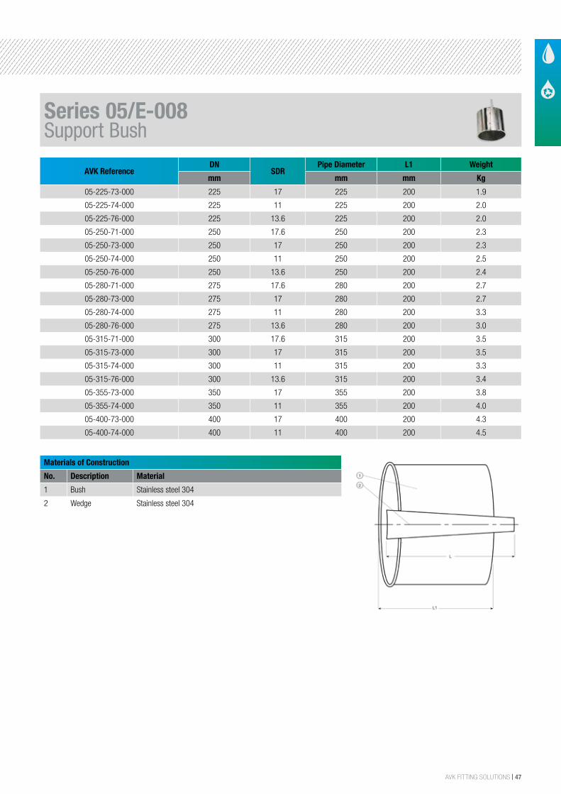
AVK FITTING SOLUTIONS | 47
AVK ReferenceDN
SDRPipe Diameter L1 Weight
mm mm mm Kg
05-225-73-000 225 17 225 200 1.9
05-225-74-000 225 11 225 200 2.0
05-225-76-000 225 13.6 225 200 2.0
05-250-71-000 250 17.6 250 200 2.3
05-250-73-000 250 17 250 200 2.3
05-250-74-000 250 11 250 200 2.5
05-250-76-000 250 13.6 250 200 2.4
05-280-71-000 275 17.6 280 200 2.7
05-280-73-000 275 17 280 200 2.7
05-280-74-000 275 11 280 200 3.3
05-280-76-000 275 13.6 280 200 3.0
05-315-71-000 300 17.6 315 200 3.5
05-315-73-000 300 17 315 200 3.5
05-315-74-000 300 11 315 200 3.3
05-315-76-000 300 13.6 315 200 3.4
05-355-73-000 350 17 355 200 3.8
05-355-74-000 350 11 355 200 4.0
05-400-73-000 400 17 400 200 4.3
05-400-74-000 400 11 400 200 4.5
Materials of Construction
No. Description Material
1 Bush Stainless steel 304
2 Wedge Stainless steel 304
For insertion in PE pipes
AVK SUPPORT BUSH, WEDGE TYPE 05/E-008
Component list:
1
1. Bush Stainless steel 3042
2. Wedge Stainless steel 304
Components may be substituted with equivalent or higher class materials without prior notification.
Reference nos. and dimensions:
AVK ref. no. DN
mm
SDR Pipe dia.
mm
L1
mm
Theoretic
weight / kg
05-025-54-002 (1)
05-032-54-002 (1)
05-040-54-002 (1)
05-050-54-002 (1)
05-063-51-000
05-063-53-000
05-063-54-000
05-063-54-002 (1)
05-063-56-000
05-075-51-000
05-075-53-000
05-075-54-000
05-075-56-000
05-090-51-000
05-090-53-000
05-090-54-000
05-090-56-000
05-110-71-000
05-110-73-000
05-110-74-000
05-110-76-000
05-125-71-000
05-125-73-000
05-125-74-000
05-125-76-000
05-140-71-000
05-140-73-000
20
25
32
40
50
50
50
50
50
65
65
65
65
80
80
80
80
100
100
100
100
125
125
125
125
140
140
-
-
-
17,6
17
11
-
13,6
17,6
17
11
13,6
17,6
17
11
13,6
17,6
17
11
13,6
17,6
17
11
13,6
17,6
17
25
32
40
50
63
63
63
63
63
75
75
75
75
90
90
90
90
110
110
110
110
125
125
125
125
140
140
36
44
54
74
150
150
150
87
150
150
150
150
150
150
150
150
150
150
150
150
150
150
150
150
150
150
150
0.1
0.1
0.2
0.3
0.4
0.4
0.4
0.6
0.4
0.5
0.5
0.5
0.5
0.7
0.7
0.7
0.7
0.8
0.8
0.8
0.8
1.0
1.0
1.0
1.0
1.1
1.1
2/324-okt-2016 09:01 CETyvkr -
The designs, materials and specifications shown are subject to change without notice. This is due to the continuous development of our product programme.
COPYRIGHT©AVK GROUP 2016
Series 05/E-008Support Bush
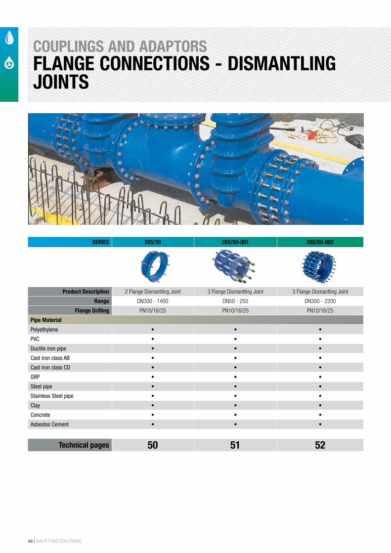
48 | AVK FITTING SOLUTIONS
SERIES 265/30 265/50-001 265/50-002
Product Description 2 Flange Dismantling Joint 3 Flange Dismantling Joint 3 Flange Dismantling Joint
Range DN300 - 1400 DN50 - 250 DN300 - 2200
Flange Drilling PN10/16/25 PN10/16/25 PN10/16/25
Pipe Material
Polyethylene • • •
PVC • • •
Ductile iron pipe • • •
Cast iron class AB • • •
Cast iron class CD • • •
GRP • • •
Steel pipe • • •
Stainless Steel pipe • • •
Clay • • •
Concrete • • •
Asbestos Cement • • •
Technical pages 50 51 52
COUPLINGS AND ADAPTORSFLANGE CONNECTIONS - DISMANTLING JOINTS
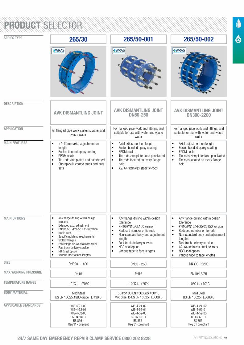
AVK FITTING SOLUTIONS | 49
SIZE
DESCRIPTION
SERIES TYPE
APPLICATION
MAIN FEATURES
MAIN OPTIONS
MAX WORKING PRESSURE
TEMPERATURE RANGE
BODY MATERIAL
APPLICABLE STANDARDS
24/7 SAME DAY EMERGENCY REPAIR CLAMP SERVICE 0800 202 8228
265/30
AVK DISMANTLING JOINT
All flanged pipe work systems water and waste water
• +/- 60mm axial adjustment on length
• Fusion bonded epoxy coating• EPDM seals• Tie-rods zinc plated and passivated• Sheraplex® coated studs and nuts
sets
DN300 - 1400
• Any flange drilling within design tolerance
• Extended axial adjustment• PN10/PN16/PN25/CL150 version.• No tie-rods• Specific notching requirements• Slotted flanges• Fastenings A2, A4 stainless steel• Fast track delivery service• NBR seal option• Various face to face lengths
PN16
-10°C to +70°C
Mild SteelBS EN 10025:1990 grade FE 430 B
WIS-4-21-02WIS-4-52-01WIS-4-52-03BS EN 681-1
BS 8561Reg 31 compliant
265/50-001
AVK DISMANTLING JOINT DN50-250
For flanged pipe work and fittings, and suitable for use with water and waste
water
• Axial adjustment on length• Fusion bonded epoxy coating• EPDM seals• Tie-rods zinc plated and passivated• Tie-rods located on every flange
hole• A2, A4 stainless steel tie-rods
DN50 - 250
• Any flange drilling within design tolerance
• PN10/PN16/CL150 version• Reduced number of tie rods• Non-standard body and adjustment
lengths• Fast track delivery service• NBR seal option• Various face to face lengths
PN16
-10°C to +70°C
SG Iron BS EN 1563GJS 450/10 Mild Steel to BS EN 10025 FE360B.B
WIS-4-21-02WIS-4-52-01WIS-4-52-03BS EN 681-1
BS 8561Reg 31 compliant
265/50-002
AVK DISMANTLING JOINT DN300-2200
For flanged pipe work and fittings, and suitable for use with water and waste
water
• Axial adjustment on length• Fusion bonded epoxy coating• EPDM seals• Tie-rods zinc plated and passivated• Tie-rods located on every flange
hole
DN300 - 2200
• Any flange drilling within design tolerance
• PN10/PN16/PN25/CL150 version• Reduced number of tie rods• Non-standard body and adjustment
lengths• Fast track delivery service• A2, A4 stainless steel tie-rods• NBR seal option• Various face to face lengths
PN10/16/25
-10°C to +70°C
Mild SteelBS EN 10025 FE360B.B
WIS-4-21-02WIS-4-52-01WIS-4-52-03BS EN 681-1
BS 8561Reg 31 compliant
PRODUCT SELECTOR
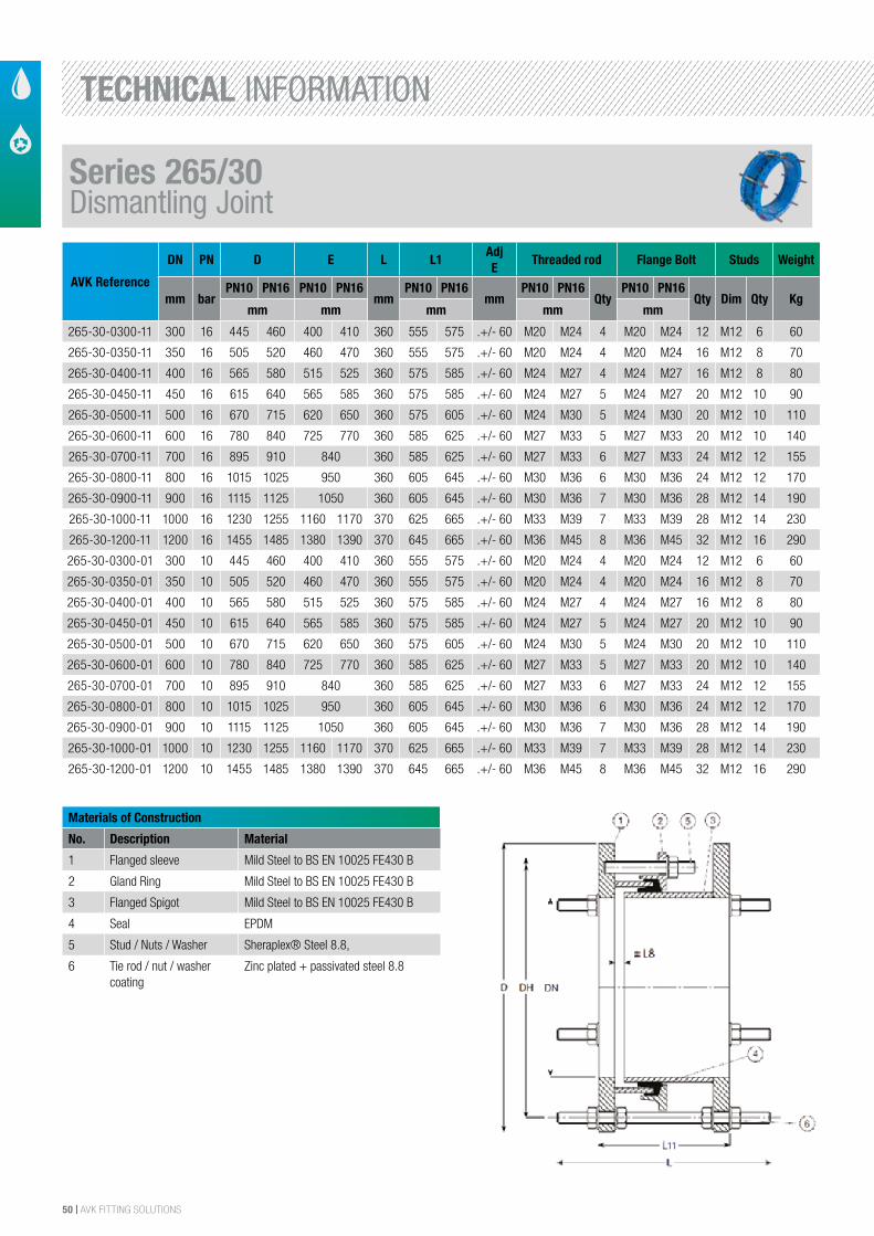
50 | AVK FITTING SOLUTIONS
AVK Reference
DN PN D E L L1AdjE
Threaded rod Flange Bolt Studs Weight
mm barPN10 PN16 PN10 PN16
mmPN10 PN16
mmPN10 PN16
QtyPN10 PN16
Qty Dim Qty Kgmm mm mm mm mm
265-30-0300-11 300 16 445 460 400 410 360 555 575 .+/- 60 M20 M24 4 M20 M24 12 M12 6 60
265-30-0350-11 350 16 505 520 460 470 360 555 575 .+/- 60 M20 M24 4 M20 M24 16 M12 8 70
265-30-0400-11 400 16 565 580 515 525 360 575 585 .+/- 60 M24 M27 4 M24 M27 16 M12 8 80
265-30-0450-11 450 16 615 640 565 585 360 575 585 .+/- 60 M24 M27 5 M24 M27 20 M12 10 90
265-30-0500-11 500 16 670 715 620 650 360 575 605 .+/- 60 M24 M30 5 M24 M30 20 M12 10 110
265-30-0600-11 600 16 780 840 725 770 360 585 625 .+/- 60 M27 M33 5 M27 M33 20 M12 10 140
265-30-0700-11 700 16 895 910 840 360 585 625 .+/- 60 M27 M33 6 M27 M33 24 M12 12 155
265-30-0800-11 800 16 1015 1025 950 360 605 645 .+/- 60 M30 M36 6 M30 M36 24 M12 12 170
265-30-0900-11 900 16 1115 1125 1050 360 605 645 .+/- 60 M30 M36 7 M30 M36 28 M12 14 190
265-30-1000-11 1000 16 1230 1255 1160 1170 370 625 665 .+/- 60 M33 M39 7 M33 M39 28 M12 14 230
265-30-1200-11 1200 16 1455 1485 1380 1390 370 645 665 .+/- 60 M36 M45 8 M36 M45 32 M12 16 290
265-30-0300-01 300 10 445 460 400 410 360 555 575 .+/- 60 M20 M24 4 M20 M24 12 M12 6 60
265-30-0350-01 350 10 505 520 460 470 360 555 575 .+/- 60 M20 M24 4 M20 M24 16 M12 8 70
265-30-0400-01 400 10 565 580 515 525 360 575 585 .+/- 60 M24 M27 4 M24 M27 16 M12 8 80
265-30-0450-01 450 10 615 640 565 585 360 575 585 .+/- 60 M24 M27 5 M24 M27 20 M12 10 90
265-30-0500-01 500 10 670 715 620 650 360 575 605 .+/- 60 M24 M30 5 M24 M30 20 M12 10 110
265-30-0600-01 600 10 780 840 725 770 360 585 625 .+/- 60 M27 M33 5 M27 M33 20 M12 10 140
265-30-0700-01 700 10 895 910 840 360 585 625 .+/- 60 M27 M33 6 M27 M33 24 M12 12 155
265-30-0800-01 800 10 1015 1025 950 360 605 645 .+/- 60 M30 M36 6 M30 M36 24 M12 12 170
265-30-0900-01 900 10 1115 1125 1050 360 605 645 .+/- 60 M30 M36 7 M30 M36 28 M12 14 190
265-30-1000-01 1000 10 1230 1255 1160 1170 370 625 665 .+/- 60 M33 M39 7 M33 M39 28 M12 14 230
265-30-1200-01 1200 10 1455 1485 1380 1390 370 645 665 .+/- 60 M36 M45 8 M36 M45 32 M12 16 290
Materials of Construction
No. Description Material
1 Flanged sleeve Mild Steel to BS EN 10025 FE430 B
2 Gland Ring Mild Steel to BS EN 10025 FE430 B
3 Flanged Spigot Mild Steel to BS EN 10025 FE430 B
4 Seal EPDM
5 Stud / Nuts / Washer Sheraplex® Steel 8.8,
6 Tie rod / nut / washer coating
Zinc plated + passivated steel 8.8
Forfurtherdetailsseesection"TechnicalInformation".Thedesigns,materialsandspecificationsshownaresubjecttochangewithoutnoticeduetothecontinuousdevelopmentofourproductprogramme.
COPYRIGHT©AVKGROUPA/S2013 DS011216
MATERIALS OF CONSTRUCTION
No. DESCRIpTION Material1 Flanges MildSteeltoBSEN10025-2S235JR2 GlandRing MildSteeltoBSEN10025-2S235JR3 Body MildSteeltoBSEN10025-2S235JR4 Seal EPDMrubbertoBSEN681-15 Stud,Nuts,Washer Sheraplex®Steel8.8toWIS4-52-036 TieRod,Nut,Washer ZincPlatedandPassivated,SteelGrade4.6 Coating FusionBondedEpoxyCoatingtoWIS4-52-01orWetSprayedDependentuponSize
AVKUK8Rushmills,Northampton,NN47YB,EnglandTel.+44(0)1604601188-Email:[email protected]©AVKGROUPA/S2013
AVk DISMANTLING JOINT, pN10/16/25 265/30
DIMENSIONS & WEIGHTS D DH L Adjustment Threaded Flange Rod Bolt pN10 pN16 pN10 pN16 L11 pN10 pN16 L8 pN10 pN16 pN10 pN16 Stud WeightRef No. DN mm mm mm mm mm mm mm mm mm mm Qty Dim Dim Qty Din Qty kg265-30-0300XY 300 445 460 400 410 360 555 575 .+/-60 M20 M24 4 M20 M24 12 M12 6 60265-30-0350XY 350 505 520 460 470 360 555 575 .+/-60 M20 M24 4 M20 M24 16 M12 8 70265-30-0400XY 400 565 580 515 525 360 575 585 .+/-60 M24 M27 4 M24 M27 16 M12 8 80265-30-0450XY 450 615 640 565 585 360 575 585 .+/-60 M24 M27 5 M24 M27 20 M12 10 90265-30-0500XY 500 670 715 620 650 360 575 605 .+/-60 M24 M30 5 M24 M30 20 M12 10 110265-30-0600XY 600 780 840 725 770 360 585 625 .+/-60 M27 M33 5 M27 M33 20 M12 10 140265-30-0700XY 700 895 910 840 360 585 625 .+/-60 M27 M33 6 M27 M33 24 M12 12 155265-30-0800XY 800 1015 1025 950 360 605 645 .+/-60 M30 M36 6 M30 M36 24 M12 12 170265-30-0900XY 900 1115 1125 1050 360 605 645 .+/-60 M30 M36 7 M30 M36 28 M12 14 190265-30-1000XY1000 1230 1255 1160 1170370 625 665 .+/-60 M33 M39 7 M33 M39 28 M12 14 230265-30-1200XY1200 1455 1485 1380 1390370 645 665 .+/-60 M36 M45 8 M36 M45 32 M12 16 290265-30-1400XY1400 1675 _ 1590 _ 370 665 _ .+/-60 M39 _ 9 M39 _ 36 M12 18 580265-30-1600XY1600 _ 1930 _ 1820380 _ 675 .+/-60 _ M52 10 _ M52 40 M12 20 600
X=0PN10X=1PN16X=2PN25Y=0withoutTie-rodsY=1withTie-rods
Series 265/30Dismantling Joint
TECHNICAL INFORMATION
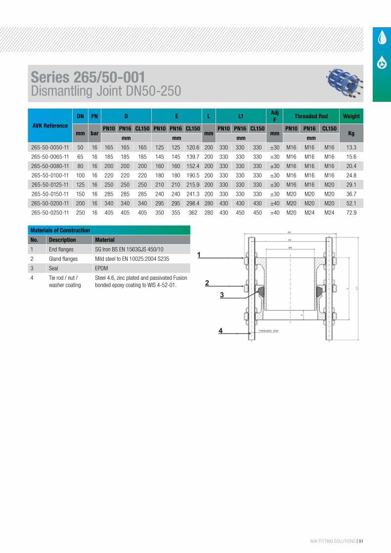
AVK FITTING SOLUTIONS | 51
AVK Reference
DN PN D E L L1Adj F
Threaded Rod Weight
mm barPN10 PN16 CL150 PN10 PN16 CL150
mmPN10 PN16 CL150
mmPN10 PN16 CL150
Kgmm mm mm mm
265-50-0050-11 50 16 165 165 165 125 125 120.6 200 330 330 330 ±30 M16 M16 M16 13.3
265-50-0065-11 65 16 185 185 185 145 145 139.7 200 330 330 330 ±30 M16 M16 M16 15.6
265-50-0080-11 80 16 200 200 200 160 160 152.4 200 330 330 330 ±30 M16 M16 M16 20.4
265-50-0100-11 100 16 220 220 220 180 180 190.5 200 330 330 330 ±30 M16 M16 M16 24.8
265-50-0125-11 125 16 250 250 250 210 210 215.9 200 330 330 330 ±30 M16 M16 M20 29.1
265-50-0150-11 150 16 285 285 285 240 240 241.3 200 330 330 330 ±30 M20 M20 M20 36.7
265-50-0200-11 200 16 340 340 340 295 295 298.4 280 430 430 430 ±40 M20 M20 M20 52.1
265-50-0250-11 250 16 405 405 405 350 355 362 280 430 450 450 ±40 M20 M24 M24 72.9
Materials of Construction
No. Description Material
1 End flanges SG Iron BS EN 1563GJS 450/10
2 Gland flanges Mild steel to EN 10025:2004 S235
3 Seal EPDM
4 Tie rod / nut / washer coating
Steel 4.6, zinc plated and passivated Fusion bonded epoxy coating to WIS 4-52-01.
AVK DISMANTLING JOINT, PN10/PN16/CL150 DN50 - DN250
265/50-001
TESTS 1.5 PN. SERVICE CONDITIONS
Maximum Working Pressure: 10/16 Bar / CL150Temperature Range: -10°C to +70°C.
Insulation essential for temperatures of 0°C and below.
MATERIALS OF CONSTRUCTION
No. DESCRIPTION MATERIAL1 End Flanges SG Iron BS EN 1563GJS 450/102 Gland Flange Mild steel to EN 10025:2004 S235.3 Seal EPDM rubber to BS EN 681-1.4 Tie Rod, Nut Steel 4.6, zinc plated and
+ Washer passivated. Fusion bondedCoating epoxy coating to WIS 4-52-01.
Northampton Office8 Rushmills, Northampton,NN 4 7YB England, UK.Tel.: +44 (0) 1604 601188Fax.: +44 (0) 1604 604818AVK UK Limited
Chesterfield OfficeColliery Close, Ireland Ind. Est., Staveley,Chesterfield, S43 3FH England, UK.Tel.: +44 (0) 1246 479100Fax.: +44 (0) 1246 479200 www.avkuk.co.uk
APPLICABLE STANDARDS & APPROVALS
Standard Flanges & Drillings:BS EN 1092-2 PN10BS EN 1092-2 PN16BS 1560 ANSI CL150
All with flat face or raised face option.Other standards available on request.
Coating: WIS 4-52-01.
Materials WRAS approved.
DIMENSIONS & WEIGHTS
Ref No. AdjustmentDN PN10 PN16 CL150 PN10 PN16 CL150 L PN10 PN16 CL150 F PN10 PN16 CL150 PN10 PN16 CL150
mm mm mm mm mm mm mm mm mm mm mm mm mm mm mm Kg Kg Kg
265-50-0050-X-1-0 50 165 165 165 125 125 120.6 200 330 330 330 ±30 M16 M16 M16 13.3 13.3 13.3265-50-0065-X-1-0 65 185 185 185 145 145 139.7 200 330 330 330 ±30 M16 M16 M16 15.6 15.6 15.6265-50-0080-X-1-0 80 200 200 200 160 160 152.4 200 330 330 330 ±30 M16 M16 M16 20.4 20.4 18265-50-0100-X-1-0 100 220 220 220 180 180 190.5 200 330 330 330 ±30 M16 M16 M16 24.8 24.8 24.8265-50-0125-X-1-0 125 250 250 250 210 210 215.9 200 330 330 330 ±30 M16 M16 M20 29.1 29.1 31.1265-50-0150-X-1-0 150 285 285 285 240 240 241.3 200 330 330 330 ±30 M20 M20 M20 36.7 36.2 36.2265-50-0200-X-1-0 200 340 340 340 295 295 298.4 280 430 430 430 ±40 M20 M20 M20 52.1 56.4 52.1265-50-0250-X-1-0 250 405 405 405 350 355 362 280 430 450 450 ±40 M20 M24 M24 72.9 77.7 77.7
E L1 Threaded RodD Weight
1
2
3
4
Series 265/50-001Dismantling Joint DN50-250
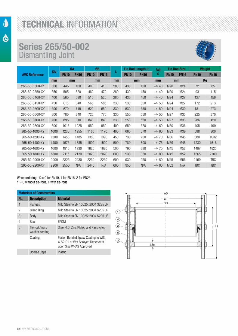
52 | AVK FITTING SOLUTIONS
AVK ReferenceDN
ØA ØBL
Tie Rod Length L1 Adj C
Tie Rod Size Weight
PN10 PN16 PN10 PN16 PN10 PN16 PN10 PN16 PN10 PN16
mm mm mm mm mm mm mm Kg
265-50-0300-XY 300 445 460 400 410 280 430 450 +/- 40 M20 M24 72 85
265-50-0350-XY 350 505 520 460 470 280 430 450 +/- 40 M20 M24 93 115
265-50-0400-XY 400 565 580 515 525 280 430 450 +/- 40 M24 M27 127 156
265-50-0450-XY 450 615 640 565 585 330 530 550 +/- 50 M24 M27 172 213
265-50-0500-XY 500 670 715 620 650 330 530 550 +/- 50 M24 M30 181 273
265-50-0600-XY 600 780 840 725 770 330 550 550 +/- 50 M27 M33 225 370
265-50-0700-XY 700 895 910 840 840 330 550 550 +/- 50 M27 M33 286 420
265-50-0800-XY 800 1015 1025 950 950 400 650 670 +/- 60 M30 M36 405 499
265-50-1000-XY 1000 1230 1255 1160 1170 400 660 670 +/- 60 M33 M39 688 900
265-50-1200-XY 1200 1455 1485 1380 1390 450 730 750 +/- 70 M36 M45 880 1032
265-50-1400-XY 1400 1675 1685 1590 1590 500 780 800 +/- 75 M39 M45 1230 1518
265-50-1600-XY 1600 1915 1930 1820 1820 500 790 830 +/- 75 M45 M52 1497 1823
265-50-1800-XY 1800 2115 2130 2020 2020 600 930 930 +/- 80 M45 M52 1865 2100
265-50-2000-XY 2000 2325 2230 2230 2230 600 930 950 +/- 80 M45 M56 2169 TBC
265-50-2200-XY 2200 2550 N/A 2440 N/A 600 950 N/A +/- 80 M52 N/A TBC TBC
Materials of Construction
No. Description Material
1 Flanges Mild Steel to EN 10025: 2004 S235 JR
2 Gland Ring Mild Steel to EN 10025: 2004 S235 JR
3 Body Mild Steel to EN 10025: 2004 S235 JR
4 Seal EPDM
5 Tie rod / nut / washer coating
Steel 4.6, Zinc Plated and Passivated
Coating Fusion Bonded Epoxy Coating to WIS 4-52-01 or Wet Sprayed Dependent upon Size WRAS Approved
Domed Caps Plastic
The designs, materials and specifications shown are subject to change without notice. This is due to the continuous development of our product programme.
Version no. 102 - 8-2-2016 11:14
AVK DISMANTLING JOINT WITH TIE RODS & CENTRE FLANGEDN 300-2200
265/50002
1
4
2
5
3
øD
DN
øE
L1L
L8±
Tie rod size DN PN 10 PN 16
300 M20 M24 350 M20 M24 400 M24 M27 450 M24 M27 500 M24 M27 600 M27 M33 700 M27 M33 800 M30 M36 1000 M33 M39 1200 M36 M45 1400 M39 M45 1600 M45 M52 1800 M45 M52 2000 M45 M52 2200 M52 -
Component List:
1. Flange Mild steel to BS EN 10025 FE360B. 2. Gland ring Mild steel to BS EN 10025 FE360B.B.
3. Spigot Mild steel to BS EN 10025 FE360B.B. 4. Seal EPDM rubber to BS EN 681-1.
5. Tie-rod, nut and washer Steel 4.6, zinc plated and passivated
Components may be substituted with equivalent or higher class materials without prior notification.
Reference Nos. and Dimensions:
AVK ref. nosDNmm
Flangedrilling
ØD mm
Emm
Lmm
L1mm
L8 mm
Theoretic.weight
kg
265-50-0300-01 300 PN10 445 400 280 450 40 72265-50-0300-11 300 PN16 460 410 280 450 40 85265-50-0350-01 350 PN10 505 460 280 450 40 93265-50-0350-11 350 PN16 520 470 280 450 40 115265-50-0400-01 400 PN10 565 515 280 280 40 127265-50-0400-11 400 PN16 580 525 280 450 40 156265-50-0450-01 450 PN10 615 565 330 550 50 172265-50-0450-11 450 PN16 640 585 330 550 50 213265-50-0500-01 500 PN10 670 620 330 550 50 181265-50-0500-11 500 PN16 715 650 330 550 50 273265-50-0600-01 600 PN10 780 725 330 550 50 210265-50-0600-11 600 PN16 840 770 330 550 50 342265-50-0700-01 700 PN10 895 840 330 550 50 268265-50-0700-11 700 PN16 910 840 330 550 50 342265-50-0800-01 800 PN10 1015 950 400 670 60 405265-50-0800-11 800 PN16 1025 950 400 670 60 499265-50-1000-01 1000 PN10 1230 1160 400 670 60 688265-50-1000-11 1000 PN16 1255 1170 400 670 60 900265-50-1200-01 1200 PN10 1455 1380 450 750 70 880265-50-1200-11 1200 PN16 1485 1390 450 750 70 1032
3/33/32/3
When ordering: X = 0 for PN10, 1 for PN16, 2 for PN25Y = 0 without tie-rods, 1 with tie-rods
Series 265/50-002Dismantling Joint
TECHNICAL INFORMATION
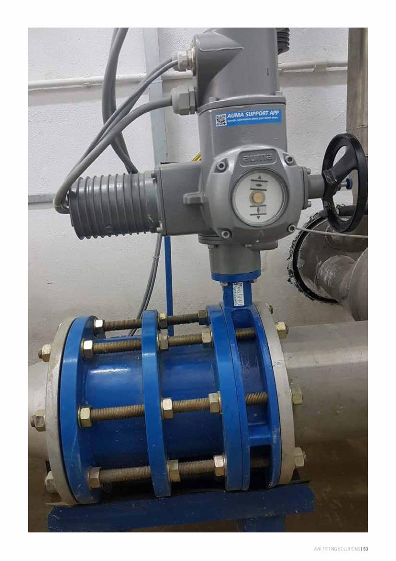
AVK FITTING SOLUTIONS | 53
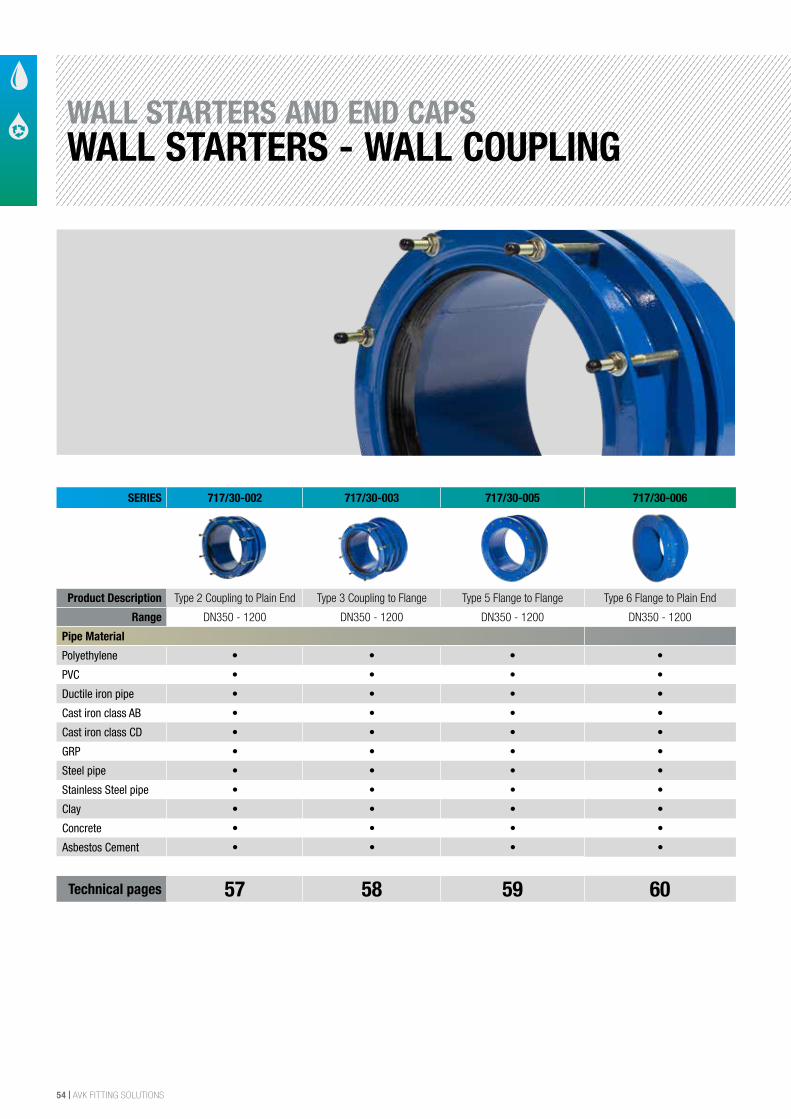
54 | AVK FITTING SOLUTIONS
WALL STARTERS AND END CAPSWALL STARTERS - WALL COUPLING
SERIES 717/30-002 717/30-003 717/30-005 717/30-006
Product Description Type 2 Coupling to Plain End Type 3 Coupling to Flange Type 5 Flange to Flange Type 6 Flange to Plain End
Range DN350 - 1200 DN350 - 1200 DN350 - 1200 DN350 - 1200
Pipe Material
Polyethylene • • • •
PVC • • • •
Ductile iron pipe • • • •
Cast iron class AB • • • •
Cast iron class CD • • • •
GRP • • • •
Steel pipe • • • •
Stainless Steel pipe • • • •
Clay • • • •
Concrete • • • •
Asbestos Cement • • • •
Technical pages 57 58 59 60
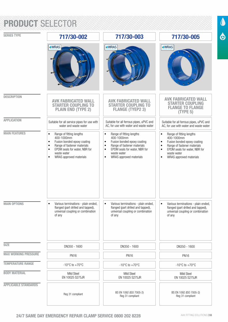
AVK FITTING SOLUTIONS | 55
SIZE
DESCRIPTION
SERIES TYPE
APPLICATION
MAIN FEATURES
MAIN OPTIONS
MAX WORKING PRESSURE
TEMPERATURE RANGE
BODY MATERIAL
APPLICABLE STANDARDS
24/7 SAME DAY EMERGENCY REPAIR CLAMP SERVICE 0800 202 8228
717/30-002 717/30-003
AVK FABRICATED WALL STARTER COUPLING TO
PLAIN END (TYPE 2)
Suitable for all service pipes for use with water and waste water
• Range of fitting lengths 400-1000mm
• Fusion bonded epoxy coating• Range of fastener materials• EPDM seals for water, NBR for
waste water• WRAS approved materials
DN350 - 1600
• Various terminations - plain ended, flanged (part drilled and tapped), universal coupling or combination of any
PN16
-10°C to +70°C
Mild Steel EN 10025 S275JR
Reg 31 compliant
AVK FABRICATED WALL STARTER COUPLING TO
FLANGE (TYEP2 3)
Suitable for all ferrous pipes, uPVC and AC, for use with water and waste water
• Range of fitting lengths 400-1000mm
• Fusion bonded epoxy coating• Range of fastener materials• EPDM seals for water, NBR for
waste water• WRAS approved materials
DN350 - 1600
• Various terminations - plain ended, flanged (part drilled and tapped), universal coupling or combination of any
PN16
-10°C to +70°C
Mild Steel EN 10025 S275JR
BS EN 1092 (ISO 7005-2)Reg 31 compliant
717/30-005
• Range of fitting lengths 400-1000mm
• Fusion bonded epoxy coating• Range of fastener materials• EPDM seals for water, NBR for
waste water• WRAS approved materials
DN350 - 1600
• Various terminations - plain ended, flanged (part drilled and tapped), universal coupling or combination of any
PN16
-10°C to +70°C
Mild Steel EN 10025 S275JR
BS EN 1092 (ISO 7005-2)Reg 31 compliant
AVK FABRICATED WALL STARTER COUPLING FLANGE TO FLANGE
(TYPE 5)
Suitable for all ferrous pipes, uPVC and AC, for use with water and waste water
PRODUCT SELECTOR
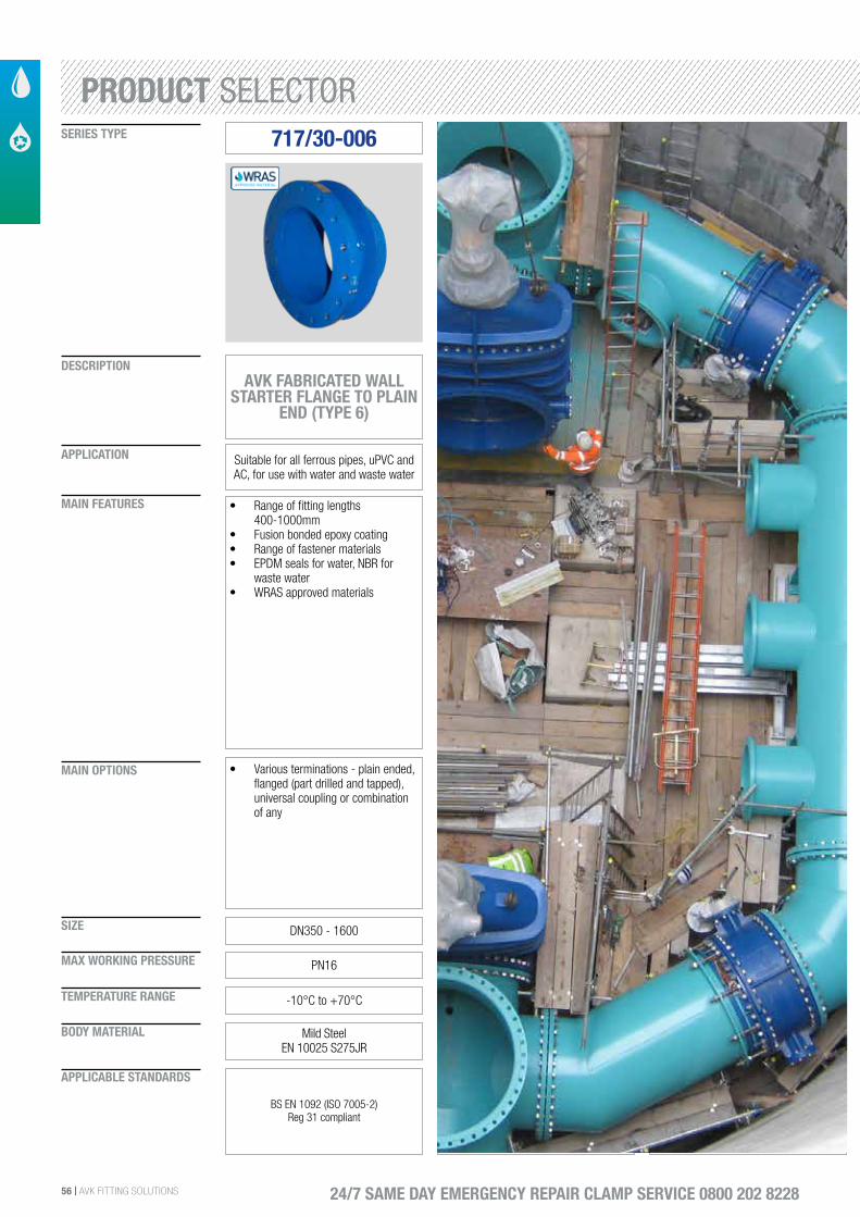
56 | AVK FITTING SOLUTIONS
SIZE
DESCRIPTION
SERIES TYPE
APPLICATION
MAIN FEATURES
MAIN OPTIONS
MAX WORKING PRESSURE
TEMPERATURE RANGE
BODY MATERIAL
APPLICABLE STANDARDS
24/7 SAME DAY EMERGENCY REPAIR CLAMP SERVICE 0800 202 8228
• Range of fitting lengths 400-1000mm
• Fusion bonded epoxy coating• Range of fastener materials• EPDM seals for water, NBR for
waste water• WRAS approved materials
DN350 - 1600
• Various terminations - plain ended, flanged (part drilled and tapped), universal coupling or combination of any
PN16
-10°C to +70°C
Mild Steel EN 10025 S275JR
BS EN 1092 (ISO 7005-2)Reg 31 compliant
717/30-006
AVK FABRICATED WALL STARTER FLANGE TO PLAIN
END (TYPE 6)
Suitable for all ferrous pipes, uPVC and AC, for use with water and waste water
PRODUCT SELECTOR
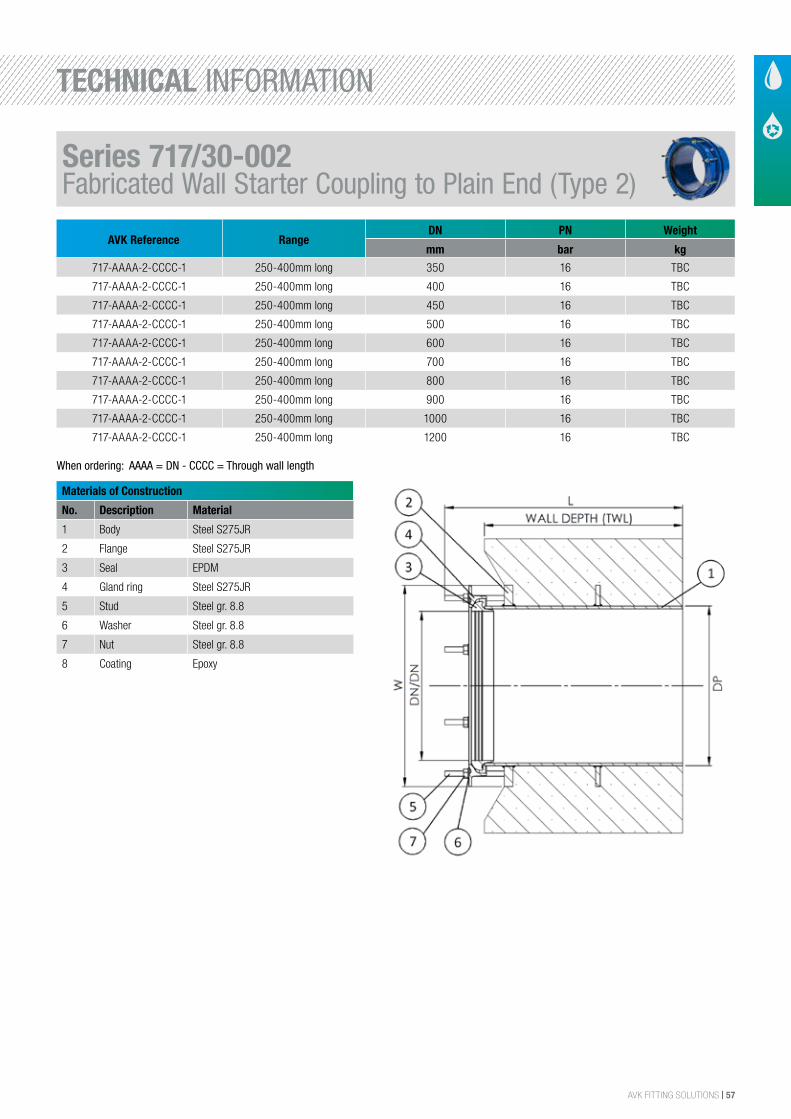
AVK FITTING SOLUTIONS | 57
AVK Reference RangeDN PN Weight
mm bar kg
717-AAAA-2-CCCC-1 250-400mm long 350 16 TBC
717-AAAA-2-CCCC-1 250-400mm long 400 16 TBC
717-AAAA-2-CCCC-1 250-400mm long 450 16 TBC
717-AAAA-2-CCCC-1 250-400mm long 500 16 TBC
717-AAAA-2-CCCC-1 250-400mm long 600 16 TBC
717-AAAA-2-CCCC-1 250-400mm long 700 16 TBC
717-AAAA-2-CCCC-1 250-400mm long 800 16 TBC
717-AAAA-2-CCCC-1 250-400mm long 900 16 TBC
717-AAAA-2-CCCC-1 250-400mm long 1000 16 TBC
717-AAAA-2-CCCC-1 250-400mm long 1200 16 TBC
Materials of Construction
No. Description Material
1 Body Steel S275JR
2 Flange Steel S275JR
3 Seal EPDM
4 Gland ring Steel S275JR
5 Stud Steel gr. 8.8
6 Washer Steel gr. 8.8
7 Nut Steel gr. 8.8
8 Coating Epoxy
TYPE 2, COUPLING TO PLAIN
AVK FABRICATED WALL STARTER 717/30-002
Component list:1
2
3
4
1.
2.
3.
4.
Body
Flange
Seal
Gland ring
Steel S275JR
Steel S275JR
EPDM rubber
Steel S275JR
5
6
7
8
5.
6.
7.
8.
Stud
Washer
Nut
Coating
Steel gr. 8.8
Steel gr. 8
Steel gr. 8
Epoxy
Components may be substituted with equivalent or higher class materials without prior notification.
Reference nos. and dimensions:
AVK ref. no. DN
mm
DN/DN Through
wall L / mm
H3
mm
L
mm
W
mm
Theoretical
weight / kg
717-0356-2-0250 350 351 - 358 250 463 328 463 45
Row to make sure table is never blank
2/203-May-2017 14:31niki -
The designs, materials and specifications shown are subject to change without notice due to the continuous development of our product range.
COPYRIGHT©AVK GROUP 2017
When ordering: AAAA = DN - CCCC = Through wall length
Series 717/30-002Fabricated Wall Starter Coupling to Plain End (Type 2)
TECHNICAL INFORMATION
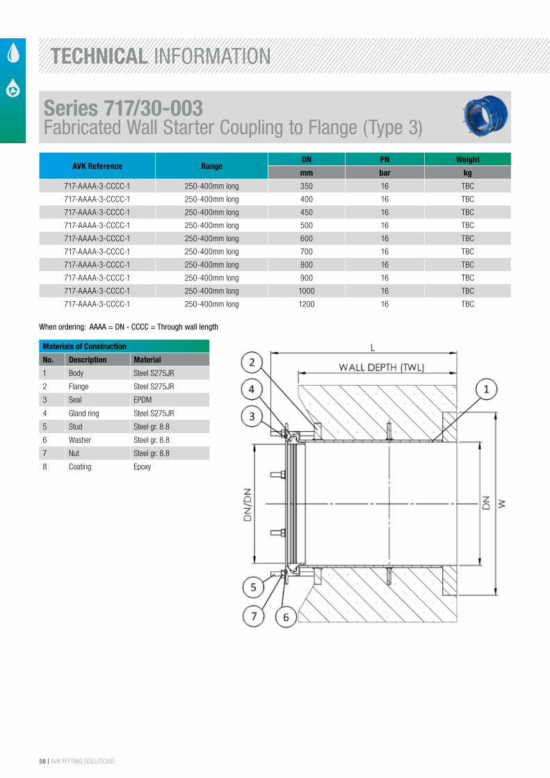
58 | AVK FITTING SOLUTIONS
AVK Reference RangeDN PN Weight
mm bar kg
717-AAAA-3-CCCC-1 250-400mm long 350 16 TBC
717-AAAA-3-CCCC-1 250-400mm long 400 16 TBC
717-AAAA-3-CCCC-1 250-400mm long 450 16 TBC
717-AAAA-3-CCCC-1 250-400mm long 500 16 TBC
717-AAAA-3-CCCC-1 250-400mm long 600 16 TBC
717-AAAA-3-CCCC-1 250-400mm long 700 16 TBC
717-AAAA-3-CCCC-1 250-400mm long 800 16 TBC
717-AAAA-3-CCCC-1 250-400mm long 900 16 TBC
717-AAAA-3-CCCC-1 250-400mm long 1000 16 TBC
717-AAAA-3-CCCC-1 250-400mm long 1200 16 TBC
Materials of Construction
No. Description Material
1 Body Steel S275JR
2 Flange Steel S275JR
3 Seal EPDM
4 Gland ring Steel S275JR
5 Stud Steel gr. 8.8
6 Washer Steel gr. 8.8
7 Nut Steel gr. 8.8
8 Coating Epoxy
TYPE 3, COUPLING TO FLANGE
AVK FABRICATED WALL STARTER 717/30-003
Component list:1
2
3
4
1.
2.
3.
4.
Body
Flange
Seal
Gland ring
Steel S275JR
Steel S275JR
EPDM rubber
Steel S275JR
5
6
7
8
5.
6.
7.
8.
Stud
Washer
Nut
Coating
Steel gr. 8.8
Steel gr. 8
Steel gr. 8
Epoxy
Components may be substituted with equivalent or higher class materials without prior notification.
Reference nos. and dimensions:
AVK ref. no. DN
mm
DN/DN Through
wall L / mm
H3
mm
L
mm
W
mm
Theoretical
weight / kg
717-0356-3-0250-1 350 351 - 358 250 520 328 520 78
Row to make sure table is never blank
2/203-May-2017 14:41niki -
The designs, materials and specifications shown are subject to change without notice due to the continuous development of our product range.
COPYRIGHT©AVK GROUP 2017
When ordering: AAAA = DN - CCCC = Through wall length
Series 717/30-003Fabricated Wall Starter Coupling to Flange (Type 3)
TECHNICAL INFORMATION
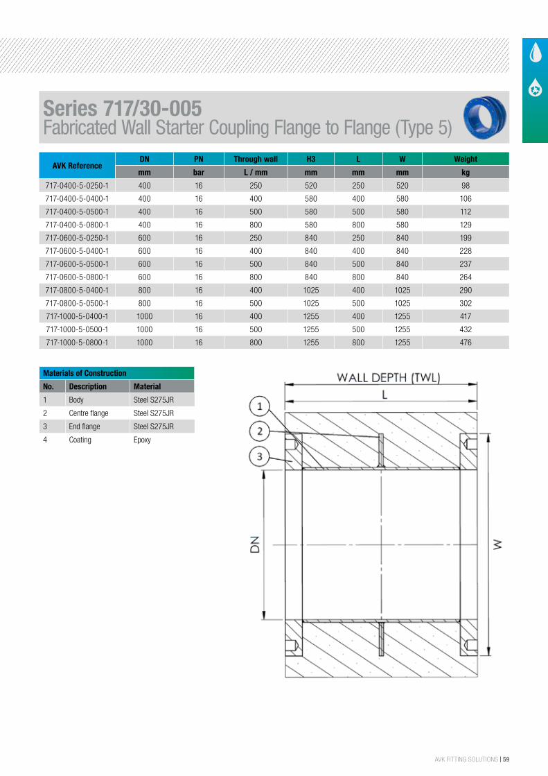
AVK FITTING SOLUTIONS | 59
AVK ReferenceDN PN Through wall H3 L W Weight
mm bar L / mm mm mm mm kg
717-0400-5-0250-1 400 16 250 520 250 520 98
717-0400-5-0400-1 400 16 400 580 400 580 106
717-0400-5-0500-1 400 16 500 580 500 580 112
717-0400-5-0800-1 400 16 800 580 800 580 129
717-0600-5-0250-1 600 16 250 840 250 840 199
717-0600-5-0400-1 600 16 400 840 400 840 228
717-0600-5-0500-1 600 16 500 840 500 840 237
717-0600-5-0800-1 600 16 800 840 800 840 264
717-0800-5-0400-1 800 16 400 1025 400 1025 290
717-0800-5-0500-1 800 16 500 1025 500 1025 302
717-1000-5-0400-1 1000 16 400 1255 400 1255 417
717-1000-5-0500-1 1000 16 500 1255 500 1255 432
717-1000-5-0800-1 1000 16 800 1255 800 1255 476
Materials of Construction
No. Description Material
1 Body Steel S275JR
2 Centre flange Steel S275JR
3 End flange Steel S275JR
4 Coating Epoxy
TYPE 5, FLANGE TO FLANGE
AVK FABRICATED WALL STARTER 717/30-005
Component list:1
2
1.
2.
Body
Centre flange
Steel S275JR
Steel S275JR
3
4
3.
4.
End flange
Coating
Steel S275JR
Epoxy
Components may be substituted with equivalent or higher class materials without prior notification.
Reference nos. and dimensions:
AVK ref. no. DN
mm
Through
wall L / mm
H3
mm
L
mm
W
mm
Theoretical
weight / kg
717-0400-5-0250-1
717-0400-5-0400-1
717-0400-5-0500-1
717-0400-5-0800-1
717-0600-5-0250-1
717-0600-5-0400-1
717-0600-5-0500-1
717-0600-5-0800-1
717-0800-5-0400-1
717-0800-5-0500-1
717-1000-5-0400-1
717-1000-5-0500-1
717-1000-5-0800-1
400
400
400
400
600
600
600
600
800
800
1000
1000
1000
250
400
500
800
250
400
500
800
400
500
400
500
800
520
580
580
580
840
840
840
840
1025
1025
1255
1255
1255
250
400
500
800
250
400
500
800
400
500
400
500
800
520
580
580
580
840
840
840
840
1025
1025
1255
1255
1255
98
106
112
129
199
228
237
264
290
302
417
432
476
Row to make sure table is never blank
2/203-May-2017 14:42niki -
The designs, materials and specifications shown are subject to change without notice due to the continuous development of our product range.
COPYRIGHT©AVK GROUP 2017
Series 717/30-005Fabricated Wall Starter Coupling Flange to Flange (Type 5)
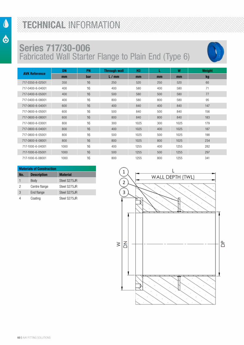
60 | AVK FITTING SOLUTIONS
Materials of Construction
No. Description Material
1 Body Steel S275JR
2 Centre flange Steel S275JR
3 End flange Steel S275JR
4 Coating Steel S275JR
TYPE 6, FLANGE TO PLAIN
AVK FABRICATED WALL STARTER 717/30-006
Component list:1
2
1.
2.
Body
Centre flange
Steel S275JR
Steel S275JR
3
4
3.
4.
End flange
Coating
Steel S275JR
Epoxy
Components may be substituted with equivalent or higher class materials without prior notification.
Reference nos. and dimensions:
AVK ref. no. DN
mm
Through
wall L / mm
H3
mm
L
mm
W
mm
Theoretical
weight / kg
717-0350-6-02501
717-0400-6-04001
717-0400-6-05001
717-0400-6-08001
717-0600-6-04001
717-0600-6-05001
717-0600-6-08001
717-0800-6-0300-1
717-0800-6-04001
717-0800-6-05001
717-0800-6-08001
717-1000-6-04001
717-1000-6-05001
717-1000-6-08001
350
400
400
400
600
600
600
800
800
800
800
1000
1000
1000
250
400
500
800
400
500
800
400
500
800
400
500
800
520
580
580
580
840
840
840
1025
1025
1025
1025
1255
1255
1255
250
400
500
800
400
500
800
300
400
500
800
400
500
800
520
580
580
580
840
840
840
1025
1025
1025
1025
1255
1255
1255
60
71
77
95
147
156
183
179
187
198
234
282
297
341
Row to make sure table is never blank
2/203-May-2017 14:43niki -
The designs, materials and specifications shown are subject to change without notice due to the continuous development of our product range.
COPYRIGHT©AVK GROUP 2017
AVK ReferenceDN PN Through wall H3 L W Weight
mm bar L / mm mm mm mm kg
717-0350-6-02501 350 16 250 520 250 520 60
717-0400-6-04001 400 16 400 580 400 580 71
717-0400-6-05001 400 16 500 580 500 580 77
717-0400-6-08001 400 16 800 580 800 580 95
717-0600-6-04001 600 16 400 840 400 840 147
717-0600-6-05001 600 16 500 840 500 840 156
717-0600-6-08001 600 16 800 840 800 840 183
717-0800-6-03001 800 16 300 1025 300 1025 179
717-0800-6-04001 800 16 400 1025 400 1025 187
717-0800-6-05001 800 16 500 1025 500 1025 198
717-0800-6-08001 800 16 800 1025 800 1025 234
717-1000-6-04001 1000 16 400 1255 400 1255 282
717-1000-6-05001 1000 16 500 1255 500 1255 297
717-1000-6-08001 1000 16 800 1255 800 1255 341
Series 717/30-006Fabricated Wall Starter Flange to Plain End (Type 6)
TECHNICAL INFORMATION
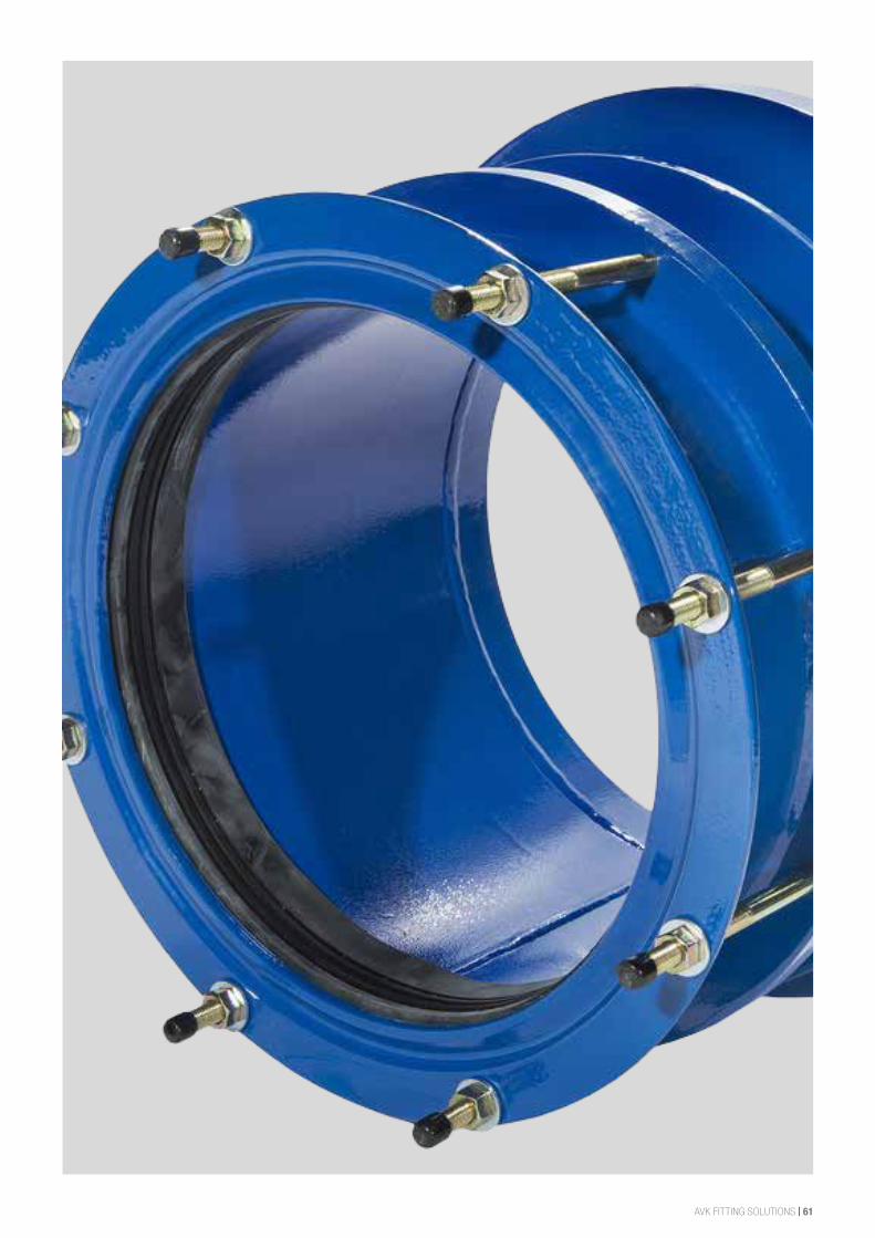
AVK FITTING SOLUTIONS | 61
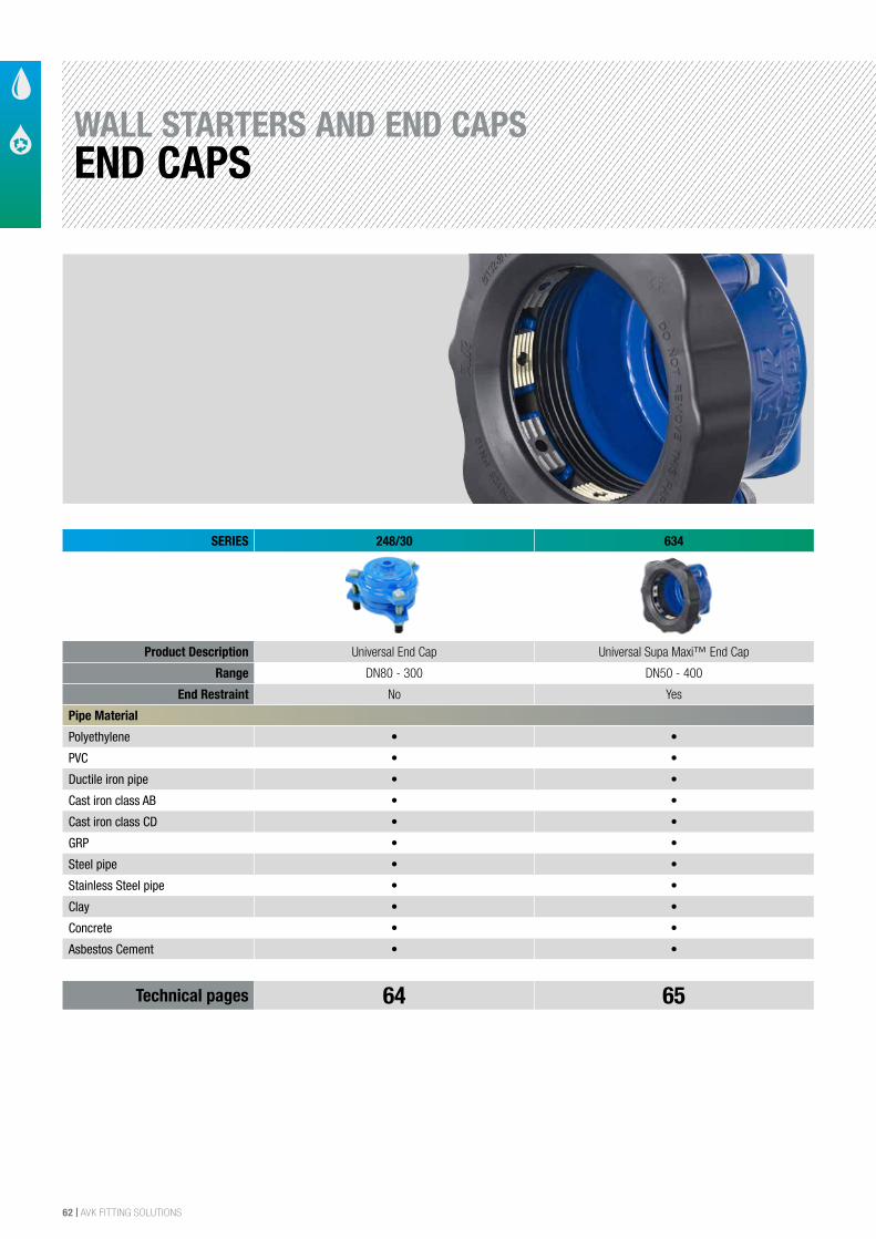
62 | AVK FITTING SOLUTIONS
SERIES 248/30 634
Product Description Universal End Cap Universal Supa Maxi™ End Cap
Range DN80 - 300 DN50 - 400
End Restraint No Yes
Pipe Material
Polyethylene • •
PVC • •
Ductile iron pipe • •
Cast iron class AB • •
Cast iron class CD • •
GRP • •
Steel pipe • •
Stainless Steel pipe • •
Clay • •
Concrete • •
Asbestos Cement • •
Technical pages 64 65
WALL STARTERS AND END CAPSEND CAPS
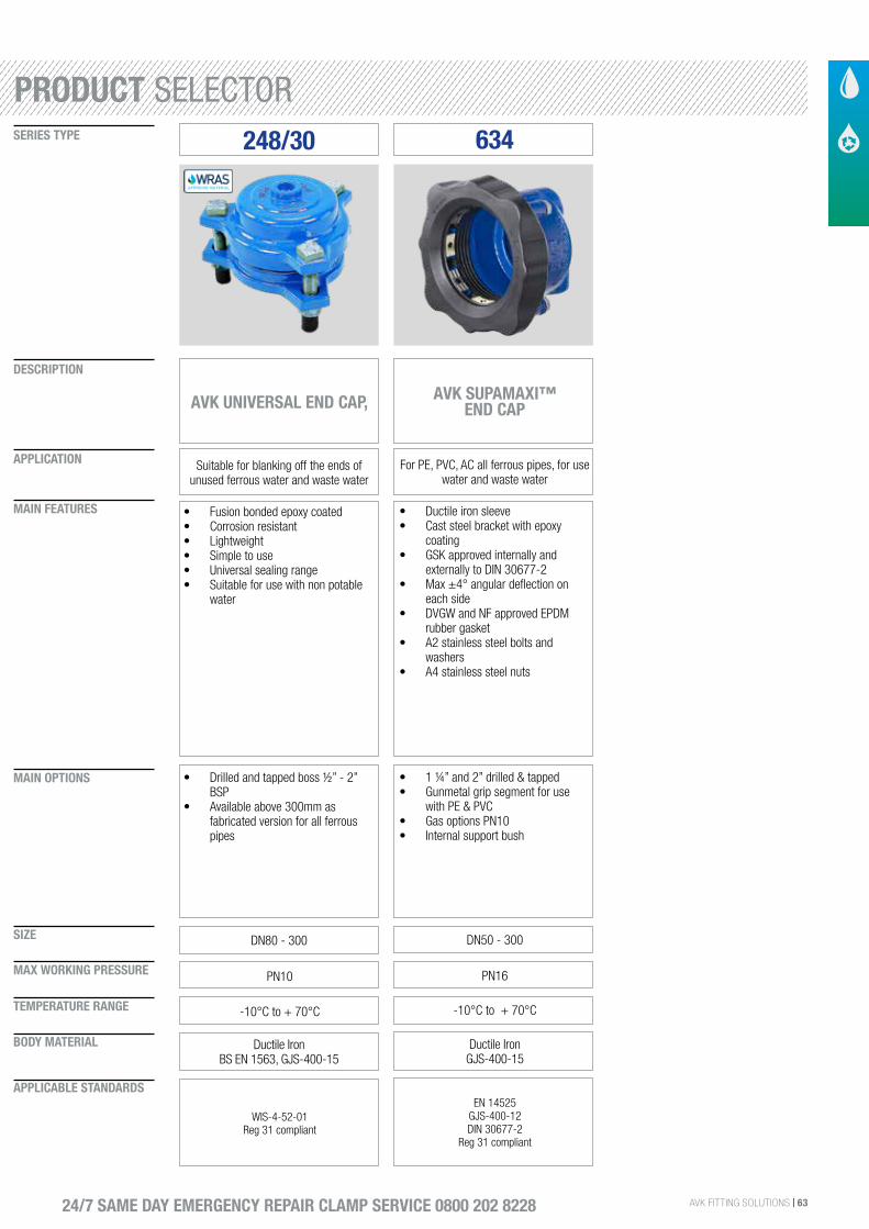
AVK FITTING SOLUTIONS | 63
SIZE
DESCRIPTION
SERIES TYPE
APPLICATION
MAIN FEATURES
MAIN OPTIONS
MAX WORKING PRESSURE
TEMPERATURE RANGE
BODY MATERIAL
APPLICABLE STANDARDS
24/7 SAME DAY EMERGENCY REPAIR CLAMP SERVICE 0800 202 8228
248/30
AVK UNIVERSAL END CAP,
Suitable for blanking off the ends of unused ferrous water and waste water
• Fusion bonded epoxy coated• Corrosion resistant• Lightweight• Simple to use• Universal sealing range• Suitable for use with non potable
water
DN80 - 300
• Drilled and tapped boss ½” - 2” BSP
• Available above 300mm as fabricated version for all ferrous pipes
PN10
-10°C to + 70°C
Ductile Iron BS EN 1563, GJS-400-15
WIS-4-52-01Reg 31 compliant
634
AVK SUPAMAXI™ END CAP
For PE, PVC, AC all ferrous pipes, for use water and waste water
• Ductile iron sleeve• Cast steel bracket with epoxy
coating• GSK approved internally and
externally to DIN 30677-2• Max ±4° angular deflection on
each side• DVGW and NF approved EPDM
rubber gasket• A2 stainless steel bolts and
washers• A4 stainless steel nuts
DN50 - 300
• 1 ¼” and 2” drilled & tapped• Gunmetal grip segment for use
with PE & PVC• Gas options PN10• Internal support bush
PN16
-10°C to + 70°C
Ductile IronGJS-400-15
EN 14525GJS-400-12DIN 30677-2
Reg 31 compliant
PRODUCT SELECTOR
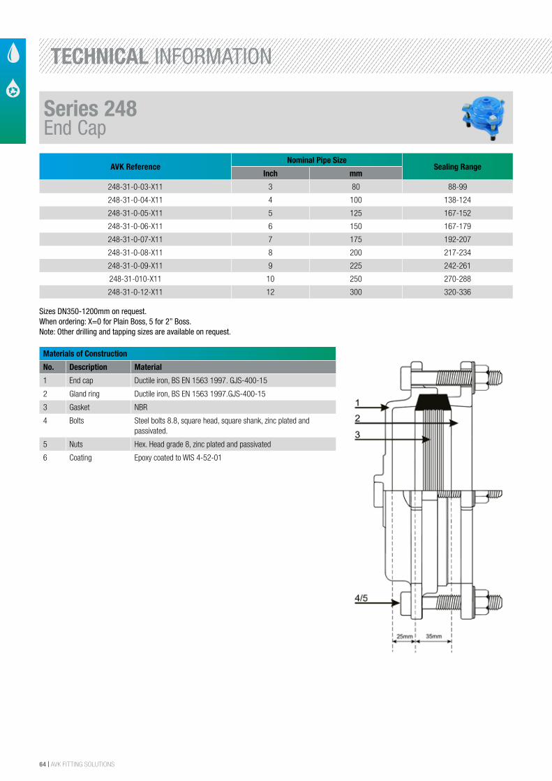
64 | AVK FITTING SOLUTIONS
AVK ReferenceNominal Pipe Size
Sealing RangeInch mm
248-31-0-03-X11 3 80 88-99
248-31-0-04-X11 4 100 138-124
248-31-0-05-X11 5 125 167-152
248-31-0-06-X11 6 150 167-179
248-31-0-07-X11 7 175 192-207
248-31-0-08-X11 8 200 217-234
248-31-0-09-X11 9 225 242-261
248-31-010-X11 10 250 270-288
248-31-0-12-X11 12 300 320-336
Materials of Construction
No. Description Material
1 End cap Ductile iron, BS EN 1563 1997. GJS-400-15
2 Gland ring Ductile iron, BS EN 1563 1997.GJS-400-15
3 Gasket NBR
4 Bolts Steel bolts 8.8, square head, square shank, zinc plated and passivated.
5 Nuts Hex. Head grade 8, zinc plated and passivated
6 Coating Epoxy coated to WIS 4-52-01
Sizes DN350-1200mm on request.When ordering: X=0 for Plain Boss, 5 for 2” Boss.Note: Other drilling and tapping sizes are available on request.
Series 248End Cap
TECHNICAL INFORMATION
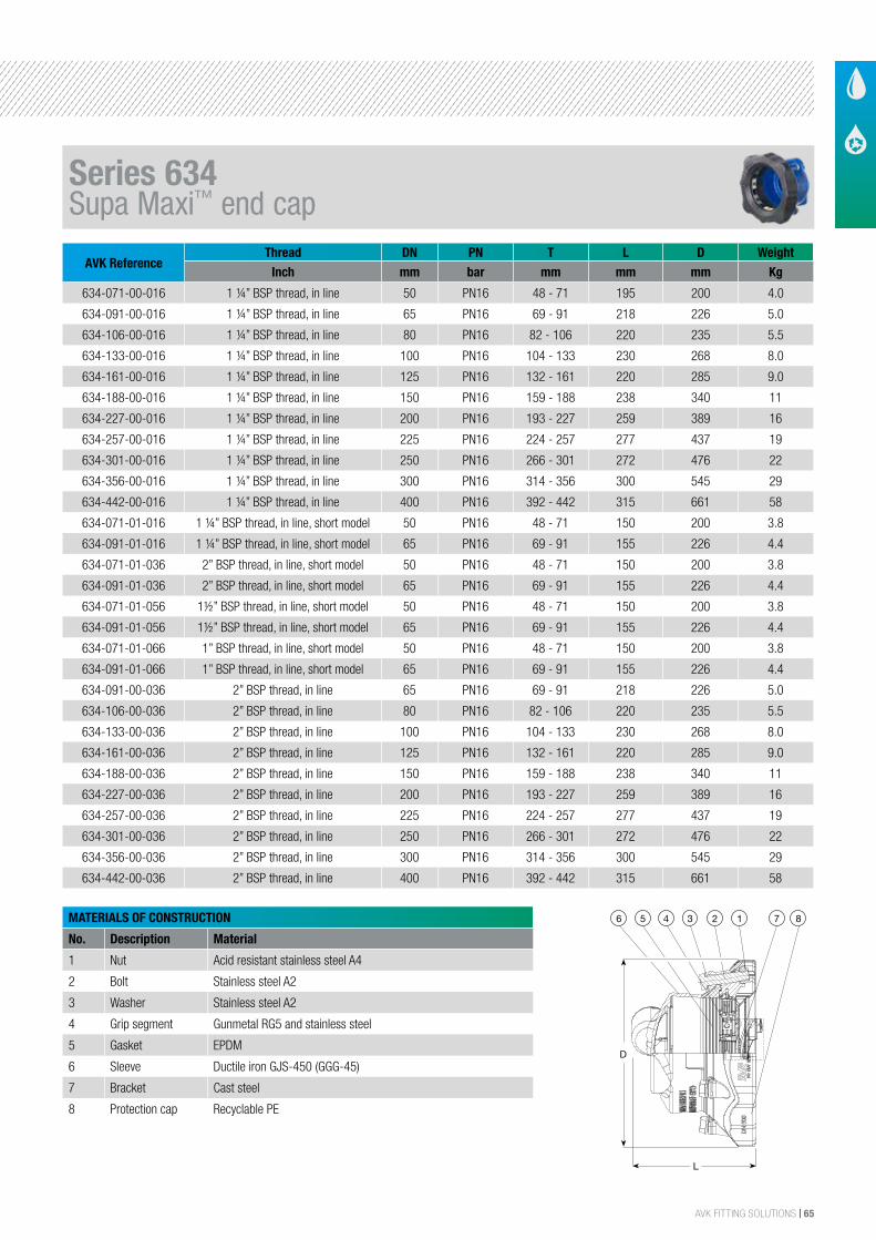
AVK FITTING SOLUTIONS | 65
AVK Reference Thread DN PN T L D Weight
Inch mm bar mm mm mm Kg
634-071-00-016 1 ¼” BSP thread, in line 50 PN16 48 - 71 195 200 4.0
634-091-00-016 1 ¼” BSP thread, in line 65 PN16 69 - 91 218 226 5.0
634-106-00-016 1 ¼” BSP thread, in line 80 PN16 82 - 106 220 235 5.5
634-133-00-016 1 ¼” BSP thread, in line 100 PN16 104 - 133 230 268 8.0
634-161-00-016 1 ¼” BSP thread, in line 125 PN16 132 - 161 220 285 9.0
634-188-00-016 1 ¼” BSP thread, in line 150 PN16 159 - 188 238 340 11
634-227-00-016 1 ¼” BSP thread, in line 200 PN16 193 - 227 259 389 16
634-257-00-016 1 ¼” BSP thread, in line 225 PN16 224 - 257 277 437 19
634-301-00-016 1 ¼” BSP thread, in line 250 PN16 266 - 301 272 476 22
634-356-00-016 1 ¼” BSP thread, in line 300 PN16 314 - 356 300 545 29
634-442-00-016 1 ¼” BSP thread, in line 400 PN16 392 - 442 315 661 58
634-071-01-016 1 ¼” BSP thread, in line, short model 50 PN16 48 - 71 150 200 3.8
634-091-01-016 1 ¼” BSP thread, in line, short model 65 PN16 69 - 91 155 226 4.4
634-071-01-036 2” BSP thread, in line, short model 50 PN16 48 - 71 150 200 3.8
634-091-01-036 2” BSP thread, in line, short model 65 PN16 69 - 91 155 226 4.4
634-071-01-056 1½” BSP thread, in line, short model 50 PN16 48 - 71 150 200 3.8
634-091-01-056 1½” BSP thread, in line, short model 65 PN16 69 - 91 155 226 4.4
634-071-01-066 1” BSP thread, in line, short model 50 PN16 48 - 71 150 200 3.8
634-091-01-066 1” BSP thread, in line, short model 65 PN16 69 - 91 155 226 4.4
634-091-00-036 2” BSP thread, in line 65 PN16 69 - 91 218 226 5.0
634-106-00-036 2” BSP thread, in line 80 PN16 82 - 106 220 235 5.5
634-133-00-036 2” BSP thread, in line 100 PN16 104 - 133 230 268 8.0
634-161-00-036 2” BSP thread, in line 125 PN16 132 - 161 220 285 9.0
634-188-00-036 2” BSP thread, in line 150 PN16 159 - 188 238 340 11
634-227-00-036 2” BSP thread, in line 200 PN16 193 - 227 259 389 16
634-257-00-036 2” BSP thread, in line 225 PN16 224 - 257 277 437 19
634-301-00-036 2” BSP thread, in line 250 PN16 266 - 301 272 476 22
634-356-00-036 2” BSP thread, in line 300 PN16 314 - 356 300 545 29
634-442-00-036 2” BSP thread, in line 400 PN16 392 - 442 315 661 58
MATERIALS OF CONSTRUCTION
No. Description Material
1 Nut Acid resistant stainless steel A4
2 Bolt Stainless steel A2
3 Washer Stainless steel A2
4 Grip segment Gunmetal RG5 and stainless steel
5 Gasket EPDM
6 Sleeve Ductile iron GJS-450 (GGG-45)
7 Bracket Cast steel
8 Protection cap Recyclable PE
The designs, materials and specifications shown are subject to change without notice. This is due to the continuous development of our product programme.
Version no. 79 - 5-12-2015 3:54
AVK SUPA MAXI™ END CAP, PN 16Universal and tensile, A2 bolts, EPDM sealing
634/00001
7 8123456
L
D
Pos. Detail Material Qty.
12 Cover PE Low/Medium Density 1
11 Gasket NBR, DIN 3535-3 1
10 Bracket Follower DI EN 1563; GJS-400-15 6
9 Bracket DI EN 1563; GJS-400-15 6
9 Grip ring Gunmetal RG5 6
8 Barbed Push Fasteners PA66 (Polyamide) 12
6 Brick SS EN 10088-1; (W 1.4401) 12
5 Nut M20 6
4 Grip ring SS EN 10088-1; (W 1.4112) 6
3 Washer M20 6
2 Bolt M20X90 6
1 Endcap DI EN 1563; GJS-400-15 1
1
2
3
511
8
6
10
9
9
4
12
XXXXXXXXXXXX
A
11
B C D E F G H I J K L M N O P
10
9
8
7
6
5
4
3
2
1
G I OC PE K MA B D F H J L N
1
10
4
7
2
11
8
5
9
6
3
Dimensions:
Application:
Standards:
Production tests:
Scale:Drawn:
Appr.: Date:
Size:
XXXXXXXXXXXX
XXXXXXXXXXXX
DK-8464 Galten, Denmark
SmTm.:
Drawing No.:
Replace for:
Rev. No.:
Projection: Weight:David 1:2
2010-01-15
A1H
SmTm.:
63420000
Kg15.89
AASoendergade 33AVK HOLDING A/S
form - including manufacture of the product shown therein - without the written consent of AVK.
Supa Maxi Endcap
Series 634
227
This drawing is issued by AVK. The drawing is confidential material. It must not be reproduced in any
Copyright © 2009 The AVK Group
DN200 193-
XXXXXXXXXXXX
CMYCMMY
CY
CMY
K
631_.pdf 1 16-06-2010 11:46:33
DN
50 3 x M14 x 75 mm 65 3 x M16 x 75 mm 80 3 x M16 x 75 mm 100 4 x M16 x 75 mm 125 4 x M16 x 75 mm 150 4 x M16 x 90 mm 200 6 x M20 x 100 mm 225 6 x M20 x 100 mm 250 6 x M20 x 100 mm 300 8 x M20 x 100 mm 400 10 x M24 x 120 mm
Component List:
1. Nut Acid resistant stainless steel A4 2. Bolt Stainless steel A2
3. Washer Stainless steel A2 4. Grip segment Gunmetal RG5 and stainless steel
5. Gasket DVGW/NF approved EPDM rubber 6. Sleeve Ductile iron GJS-450 (GGG-45)
7. Bracket Cast steel 8. Protection cap Recyclable PE
Components may be substituted with equivalent or higher class materials without prior notification.
Reference Nos. and Dimensions:
AVK ref. nosDNmm
Product PN Class
Tmm
Lmm
D mm
Theoretic.weight
kg
634-071-00-016 (1) 50 PN16 48 - 71 195 200 4.0634-071-01-016 (2) 50 PN16 48 - 71 150 200 3.8634-071-01-036 (3) 50 PN16 48 - 71 150 200 3.8634-071-01-056 (4) 50 PN16 48 - 71 150 200 3.8634-071-01-066 (5) 50 PN16 48 - 71 150 200 3.8634-091-00-016 (1) 65 PN16 69 - 91 218 226 5.0634-091-00-036 (6) 65 PN16 69 - 91 218 226 5.0634-091-01-016 (2) 65 PN16 69 - 91 155 226 4.4634-091-01-036 (3) 65 PN16 69 - 91 155 226 4.4634-091-01-056 (4) 65 PN16 69 - 91 155 226 4.4634-091-01-066 (5) 65 PN16 69 - 91 155 226 4.4634-106-00-016 (1) 80 PN16 82 - 106 220 235 5.5634-106-00-036 (6) 80 PN16 82 - 106 220 235 5.5634-133-00-016 (1) 100 PN16 104 - 133 230 268 8.0634-133-00-036 (6) 100 PN16 104 - 133 230 268 8.0634-161-00-016 (1) 125 PN16 132 - 161 220 285 9.0634-161-00-036 (6) 125 PN16 132 - 161 220 285 9.0634-188-00-016 (1) 150 PN16 159 - 188 238 340 11634-188-00-036 (6) 150 PN16 159 - 188 238 340 11
3/33/32/3
Series 634Supa Maxi™ end cap
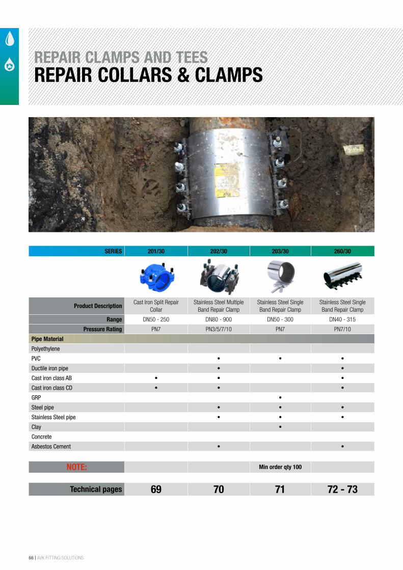
66 | AVK FITTING SOLUTIONS
REPAIR CLAMPS AND TEESREPAIR COLLARS & CLAMPS
SERIES 201/30 202/30 203/30 260/30
Product DescriptionCast Iron Split Repair
CollarStainless Steel Multiple
Band Repair ClampStainless Steel Single Band Repair Clamp
Stainless Steel Single Band Repair Clamp
Range DN50 - 250 DN80 - 900 DN50 - 300 DN40 - 315
Pressure Rating PN7 PN3/5/7/10 PN7 PN7/10
Pipe Material
Polyethylene
PVC • • •
Ductile iron pipe • •
Cast iron class AB • • •
Cast iron class CD • • •
GRP •
Steel pipe • • •
Stainless Steel pipe • • •
Clay •
Concrete
Asbestos Cement • •
NOTE: Min order qty 100
Technical pages 69 70 71 72 - 73
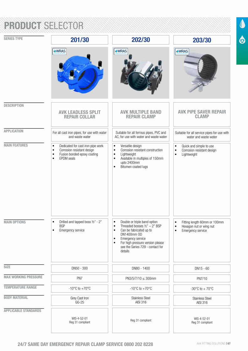
AVK FITTING SOLUTIONS | 67
SIZE
DESCRIPTION
SERIES TYPE
APPLICATION
MAIN FEATURES
MAIN OPTIONS
MAX WORKING PRESSURE
TEMPERATURE RANGE
BODY MATERIAL
APPLICABLE STANDARDS
24/7 SAME DAY EMERGENCY REPAIR CLAMP SERVICE 0800 202 8228
201/30
AVK LEADLESS SPLIT REPAIR COLLAR
For all cast iron pipes, for use with water and waste water
• Dedicated for cast iron pipe work• Corrosion resistant design• Fusion bonded epoxy coating• EPDM seals
DN50 - 300
• Drilled and tapped boss ½” - 2” BSP
• Emergency service
PN7
-10°C to +70°C
Grey Cast IronGG-25
WIS-4-52-01Reg 31 compliant
202/30
AVK MULTIPLE BAND REPAIR CLAMP
Suitable for all ferrous pipes, PVC and AC, for use with water and waste water
• Versatile design• Corrosion resistant construction• Lightweight• Available in multiples of 150mm
upto 2400mm• Bitumen coated lugs
DN80 - 1400
• Double or triple band option• Threaded bosses ½” – 2” BSP• Can be fabricated up to
DN1400mm OD• Emergency service• For high pressure version please
see the Series 729 - contact for details
PN3/5/7/10 ≤ 300mm
-10°C to +70°C
Stainless Steel AISI 316
Reg 31 compliant
203/30
AVK PIPE SAVER REPAIR CLAMP
Suitable for all service pipes for use with water and waste water
• Quick and simple to use• Corrosion resistant design• Lightweight
DN15 - 60
• Fitting length 60mm or 100mm• Hexagon nut or wing nut• Emergency service
PN7/10
-30°C to + 70°C
Stainless SteelAISI 316
WIS-4-52-01Reg 31 compliant
PRODUCT SELECTOR
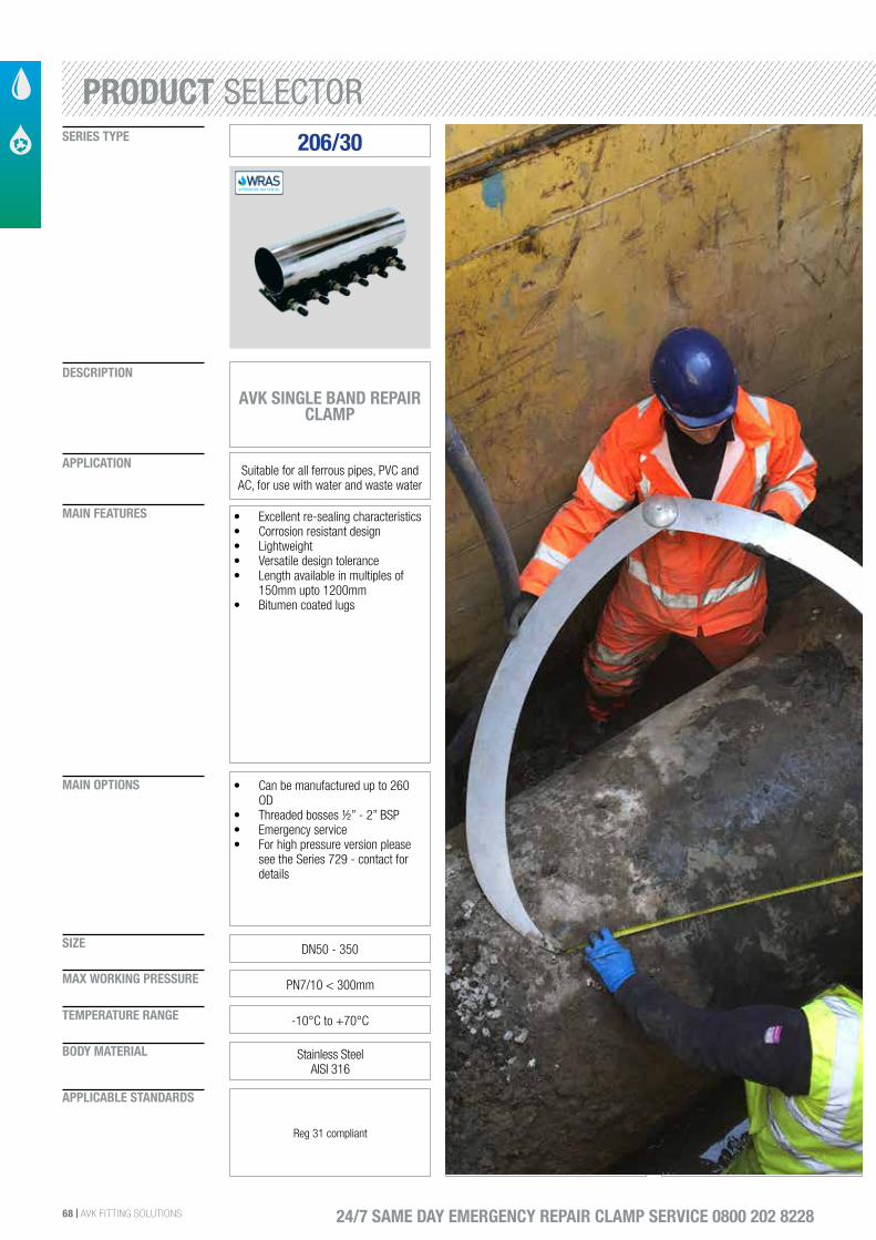
68 | AVK FITTING SOLUTIONS
SIZE
DESCRIPTION
SERIES TYPE
APPLICATION
MAIN FEATURES
MAIN OPTIONS
MAX WORKING PRESSURE
TEMPERATURE RANGE
BODY MATERIAL
APPLICABLE STANDARDS
24/7 SAME DAY EMERGENCY REPAIR CLAMP SERVICE 0800 202 8228
206/30
AVK SINGLE BAND REPAIR CLAMP
Suitable for all ferrous pipes, PVC and AC, for use with water and waste water
• Excellent re-sealing characteristics• Corrosion resistant design• Lightweight• Versatile design tolerance• Length available in multiples of
150mm upto 1200mm• Bitumen coated lugs
DN50 - 350
• Can be manufactured up to 260 OD
• Threaded bosses ½” - 2” BSP• Emergency service• For high pressure version please
see the Series 729 - contact for details
PN7/10 < 300mm
-10°C to +70°C
Stainless SteelAISI 316
Reg 31 compliant
PRODUCT SELECTOR
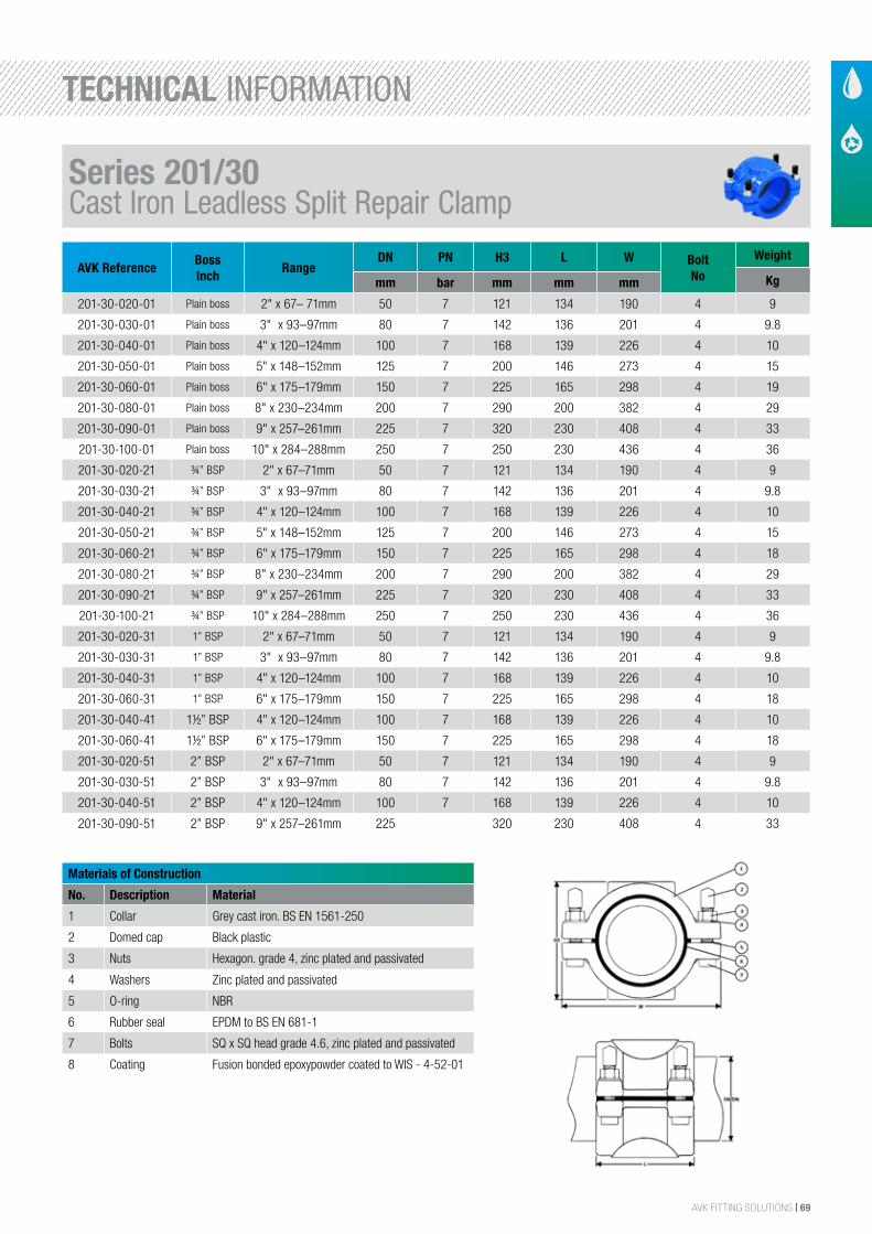
AVK FITTING SOLUTIONS | 69
AVK ReferenceBossInch
RangeDN PN H3 L W Bolt
No
Weight
Kgmm bar mm mm mm
201-30-020-01 Plain boss 2" x 67– 71mm 50 7 121 134 190 4 9
201-30-030-01 Plain boss 3" x 93–97mm 80 7 142 136 201 4 9.8
201-30-040-01 Plain boss 4" x 120–124mm 100 7 168 139 226 4 10
201-30-050-01 Plain boss 5" x 148–152mm 125 7 200 146 273 4 15
201-30-060-01 Plain boss 6" x 175–179mm 150 7 225 165 298 4 19
201-30-080-01 Plain boss 8" x 230–234mm 200 7 290 200 382 4 29
201-30-090-01 Plain boss 9" x 257–261mm 225 7 320 230 408 4 33
201-30-100-01 Plain boss 10" x 284–288mm 250 7 250 230 436 4 36
201-30-020-21 ¾” BSP 2" x 67–71mm 50 7 121 134 190 4 9
201-30-030-21 ¾” BSP 3" x 93–97mm 80 7 142 136 201 4 9.8
201-30-040-21 ¾” BSP 4" x 120–124mm 100 7 168 139 226 4 10
201-30-050-21 ¾” BSP 5" x 148–152mm 125 7 200 146 273 4 15
201-30-060-21 ¾” BSP 6" x 175–179mm 150 7 225 165 298 4 18
201-30-080-21 ¾” BSP 8" x 230–234mm 200 7 290 200 382 4 29
201-30-090-21 ¾” BSP 9" x 257–261mm 225 7 320 230 408 4 33
201-30-100-21 ¾” BSP 10" x 284–288mm 250 7 250 230 436 4 36
201-30-020-31 1” BSP 2" x 67–71mm 50 7 121 134 190 4 9
201-30-030-31 1” BSP 3" x 93–97mm 80 7 142 136 201 4 9.8
201-30-040-31 1” BSP 4" x 120–124mm 100 7 168 139 226 4 10
201-30-060-31 1” BSP 6" x 175–179mm 150 7 225 165 298 4 18
201-30-040-41 1½” BSP 4" x 120–124mm 100 7 168 139 226 4 10
201-30-060-41 1½” BSP 6" x 175–179mm 150 7 225 165 298 4 18
201-30-020-51 2” BSP 2" x 67–71mm 50 7 121 134 190 4 9
201-30-030-51 2” BSP 3" x 93–97mm 80 7 142 136 201 4 9.8
201-30-040-51 2” BSP 4" x 120–124mm 100 7 168 139 226 4 10
201-30-090-51 2” BSP 9" x 257–261mm 225 320 230 408 4 33
Materials of Construction
No. Description Material
1 Collar Grey cast iron. BS EN 1561-250
2 Domed cap Black plastic
3 Nuts Hexagon. grade 4, zinc plated and passivated
4 Washers Zinc plated and passivated
5 O-ring NBR
6 Rubber seal EPDM to BS EN 681-1
7 Bolts SQ x SQ head grade 4.6, zinc plated and passivated
8 Coating Fusion bonded epoxypowder coated to WIS - 4-52-01
Series 201/30Cast Iron Leadless Split Repair Clamp
TECHNICAL INFORMATION
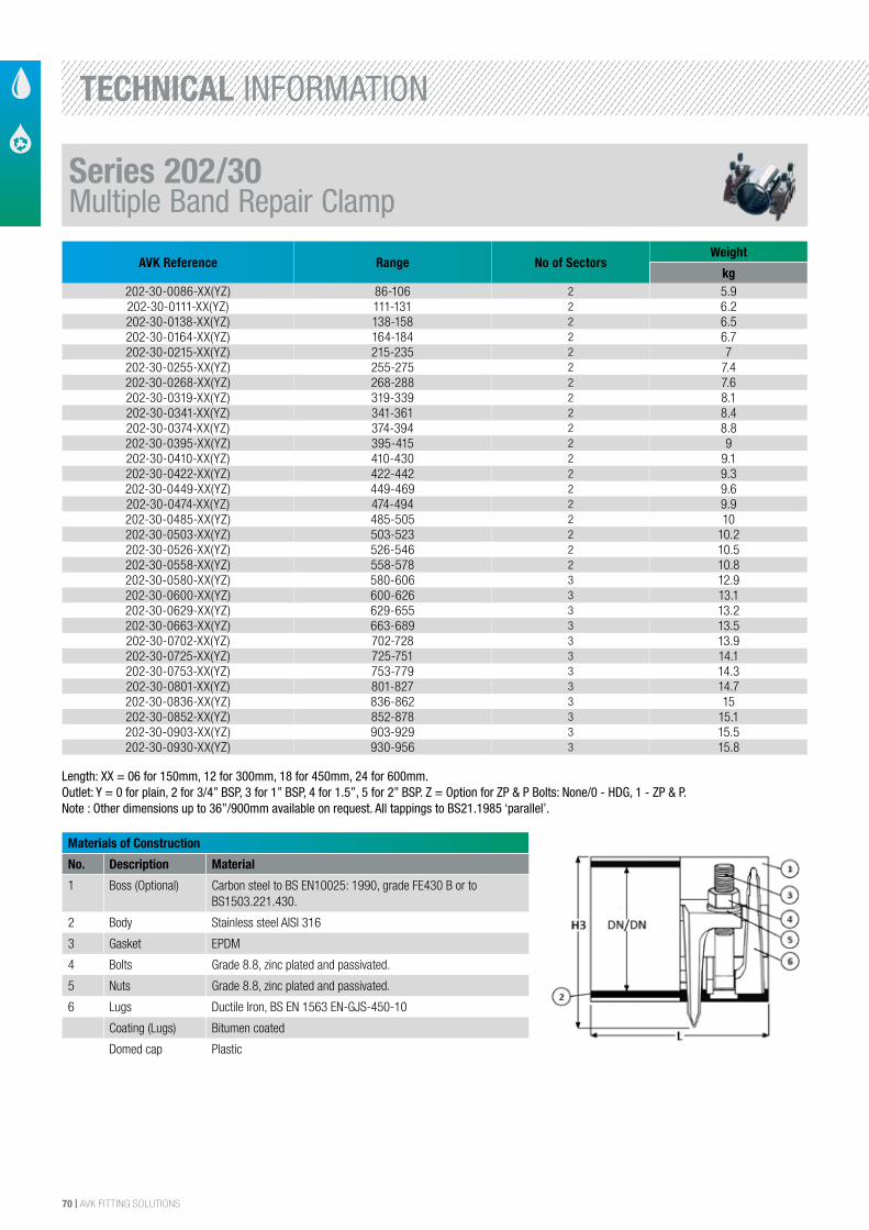
70 | AVK FITTING SOLUTIONS
AVK Reference Range No of SectorsWeight
kg 202-30-0086-XX(YZ) 86-106 2 5.9202-30-0111-XX(YZ) 111-131 2 6.2202-30-0138-XX(YZ) 138-158 2 6.5202-30-0164-XX(YZ) 164-184 2 6.7202-30-0215-XX(YZ) 215-235 2 7202-30-0255-XX(YZ) 255-275 2 7.4202-30-0268-XX(YZ) 268-288 2 7.6202-30-0319-XX(YZ) 319-339 2 8.1202-30-0341-XX(YZ) 341-361 2 8.4202-30-0374-XX(YZ) 374-394 2 8.8202-30-0395-XX(YZ) 395-415 2 9202-30-0410-XX(YZ) 410-430 2 9.1202-30-0422-XX(YZ) 422-442 2 9.3202-30-0449-XX(YZ) 449-469 2 9.6202-30-0474-XX(YZ) 474-494 2 9.9202-30-0485-XX(YZ) 485-505 2 10202-30-0503-XX(YZ) 503-523 2 10.2202-30-0526-XX(YZ) 526-546 2 10.5202-30-0558-XX(YZ) 558-578 2 10.8202-30-0580-XX(YZ) 580-606 3 12.9202-30-0600-XX(YZ) 600-626 3 13.1202-30-0629-XX(YZ) 629-655 3 13.2202-30-0663-XX(YZ) 663-689 3 13.5202-30-0702-XX(YZ) 702-728 3 13.9202-30-0725-XX(YZ) 725-751 3 14.1202-30-0753-XX(YZ) 753-779 3 14.3202-30-0801-XX(YZ) 801-827 3 14.7202-30-0836-XX(YZ) 836-862 3 15202-30-0852-XX(YZ) 852-878 3 15.1202-30-0903-XX(YZ) 903-929 3 15.5202-30-0930-XX(YZ) 930-956 3 15.8
Materials of Construction
No. Description Material
1 Boss (Optional) Carbon steel to BS EN10025: 1990, grade FE430 B or to BS1503.221.430.
2 Body Stainless steel AISI 316
3 Gasket EPDM
4 Bolts Grade 8.8, zinc plated and passivated.
5 Nuts Grade 8.8, zinc plated and passivated.
6 Lugs Ductile Iron, BS EN 1563 EN-GJS-450-10
Coating (Lugs) Bitumen coated
Domed cap Plastic
Length: XX = 06 for 150mm, 12 for 300mm, 18 for 450mm, 24 for 600mm.Outlet: Y = 0 for plain, 2 for 3/4” BSP, 3 for 1” BSP, 4 for 1.5”, 5 for 2” BSP. Z = Option for ZP & P Bolts: None/0 - HDG, 1 - ZP & P.Note : Other dimensions up to 36”/900mm available on request. All tappings to BS21.1985 ‘parallel’.
Series 202/30Multiple Band Repair Clamp
TECHNICAL INFORMATION
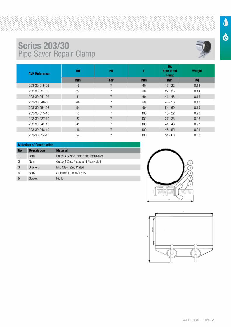
AVK FITTING SOLUTIONS | 71
AVK ReferenceDN PN L
OAPipe D ext
RangeWeight
mm bar mm mm Kg
203-30-015-06 15 7 60 15 - 22 0.12
203-30-027-06 27 7 60 27 - 35 0.14
203-30-041-06 41 7 60 41 - 48 0.16
203-30-048-06 48 7 60 48 - 55 0.18
203-30-054-06 54 7 60 54 - 60 0.19
203-30-015-10 15 7 100 15 - 22 0.20
203-30-027-10 27 7 100 27 - 35 0.23
203-30-041-10 41 7 100 41 - 48 0.27
203-30-048-10 48 7 100 48 - 55 0.29
203-30-054-10 54 7 100 54 - 60 0.30
Materials of Construction
No. Description Material
1 Bolts Grade 4.6 Zinc, Plated and Passivated
2 Nuts Grade 4 Zinc, Plated and Passivated
3 Bracket Mild Steel, Zinc Plated
4 Body Stainless Steel AISI 316
5 Gasket Nitrile
Series 203/30Pipe Saver Repair Clamp
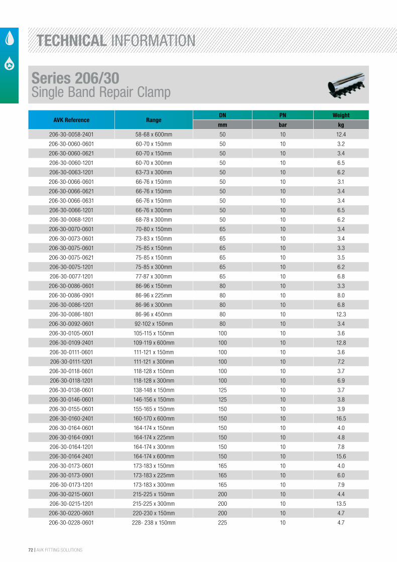
72 | AVK FITTING SOLUTIONS
AVK Reference RangeDN PN Weight
mm bar kg
206-30-0058-2401 58-68 x 600mm 50 10 12.4
206-30-0060-0601 60-70 x 150mm 50 10 3.2
206-30-0060-0621 60-70 x 150mm 50 10 3.4
206-30-0060-1201 60-70 x 300mm 50 10 6.5
206-30-0063-1201 63-73 x 300mm 50 10 6.2
206-30-0066-0601 66-76 x 150mm 50 10 3.1
206-30-0066-0621 66-76 x 150mm 50 10 3.4
206-30-0066-0631 66-76 x 150mm 50 10 3.4
206-30-0066-1201 66-76 x 300mm 50 10 6.5
206-30-0068-1201 68-78 x 300mm 50 10 6.2
206-30-0070-0601 70-80 x 150mm 65 10 3.4
206-30-0073-0601 73-83 x 150mm 65 10 3.4
206-30-0075-0601 75-85 x 150mm 65 10 3.3
206-30-0075-0621 75-85 x 150mm 65 10 3.5
206-30-0075-1201 75-85 x 300mm 65 10 6.2
206-30-0077-1201 77-87 x 300mm 65 10 6.8
206-30-0086-0601 86-96 x 150mm 80 10 3.3
206-30-0086-0901 86-96 x 225mm 80 10 8.0
206-30-0086-1201 86-96 x 300mm 80 10 6.8
206-30-0086-1801 86-96 x 450mm 80 10 12.3
206-30-0092-0601 92-102 x 150mm 80 10 3.4
206-30-0105-0601 105-115 x 150mm 100 10 3.6
206-30-0109-2401 109-119 x 600mm 100 10 12.8
206-30-0111-0601 111-121 x 150mm 100 10 3.6
206-30-0111-1201 111-121 x 300mm 100 10 7.2
206-30-0118-0601 118-128 x 150mm 100 10 3.7
206-30-0118-1201 118-128 x 300mm 100 10 6.9
206-30-0138-0601 138-148 x 150mm 125 10 3.7
206-30-0146-0601 146-156 x 150mm 125 10 3.8
206-30-0155-0601 155-165 x 150mm 150 10 3.9
206-30-0160-2401 160-170 x 600mm 150 10 16.5
206-30-0164-0601 164-174 x 150mm 150 10 4.0
206-30-0164-0901 164-174 x 225mm 150 10 4.8
206-30-0164-1201 164-174 x 300mm 150 10 7.8
206-30-0164-2401 164-174 x 600mm 150 10 15.6
206-30-0173-0601 173-183 x 150mm 165 10 4.0
206-30-0173-0901 173-183 x 225mm 165 10 6.0
206-30-0173-1201 173-183 x 300mm 165 10 7.9
206-30-0215-0601 215-225 x 150mm 200 10 4.4
206-30-0215-1201 215-225 x 300mm 200 10 13.5
206-30-0220-0601 220-230 x 150mm 200 10 4.7
206-30-0228-0601 228- 238 x 150mm 225 10 4.7
Series 206/30Single Band Repair Clamp
TECHNICAL INFORMATION
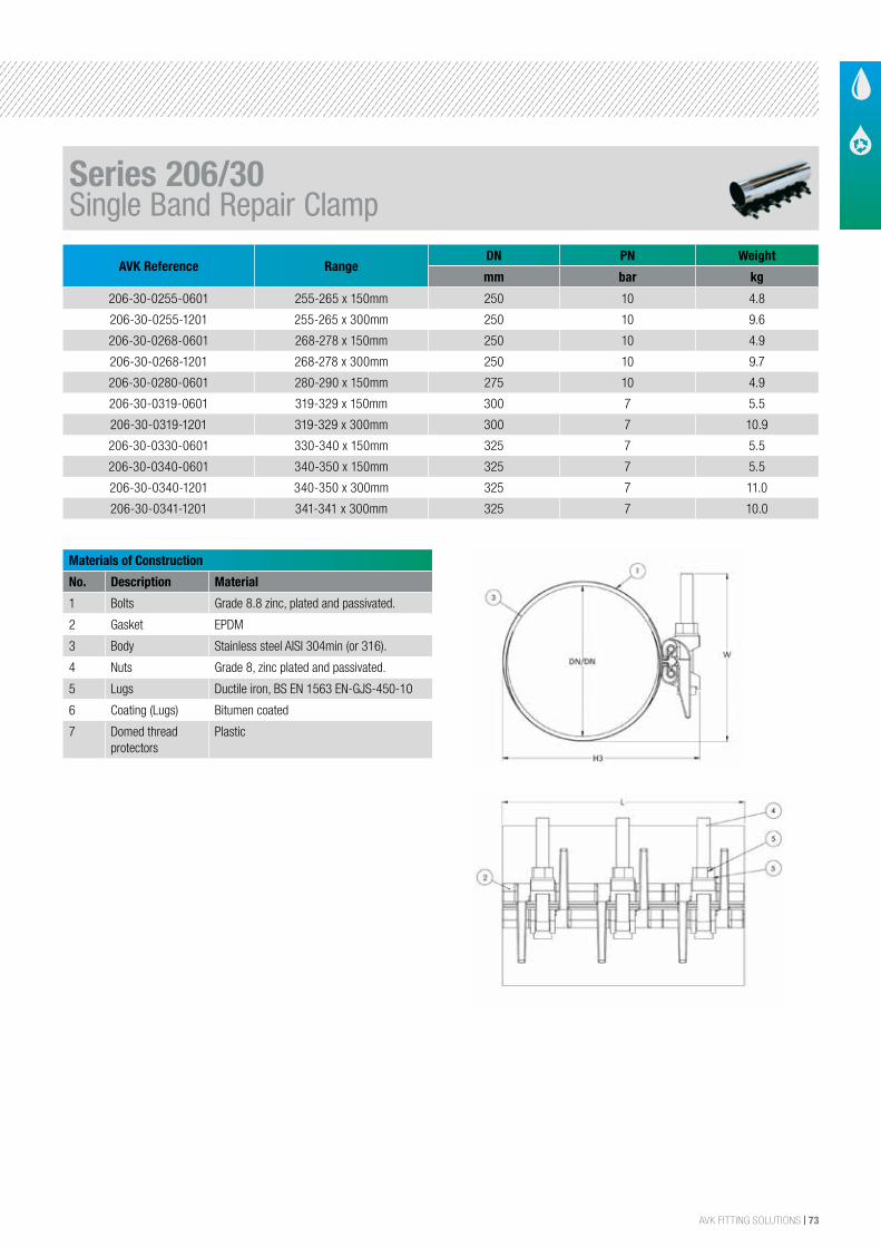
AVK FITTING SOLUTIONS | 73
AVK Reference RangeDN PN Weight
mm bar kg
206-30-0255-0601 255-265 x 150mm 250 10 4.8
206-30-0255-1201 255-265 x 300mm 250 10 9.6
206-30-0268-0601 268-278 x 150mm 250 10 4.9
206-30-0268-1201 268-278 x 300mm 250 10 9.7
206-30-0280-0601 280-290 x 150mm 275 10 4.9
206-30-0319-0601 319-329 x 150mm 300 7 5.5
206-30-0319-1201 319-329 x 300mm 300 7 10.9
206-30-0330-0601 330-340 x 150mm 325 7 5.5
206-30-0340-0601 340-350 x 150mm 325 7 5.5
206-30-0340-1201 340-350 x 300mm 325 7 11.0
206-30-0341-1201 341-341 x 300mm 325 7 10.0
Materials of Construction
No. Description Material
1 Bolts Grade 8.8 zinc, plated and passivated.
2 Gasket EPDM
3 Body Stainless steel AISI 304min (or 316).
4 Nuts Grade 8, zinc plated and passivated.
5 Lugs Ductile iron, BS EN 1563 EN-GJS-450-10
6 Coating (Lugs) Bitumen coated
7 Domed thread protectors
Plastic
Series 206/30Single Band Repair Clamp
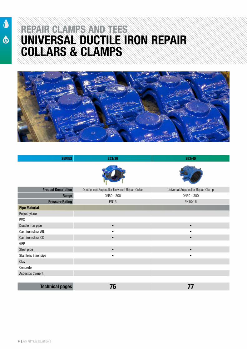
74 | AVK FITTING SOLUTIONS
REPAIR CLAMPS AND TEESUNIVERSAL DUCTILE IRON REPAIR COLLARS & CLAMPS
SERIES 253/30 253/40
Product Description Ductile Iron Supacollar Universal Repair Collar Universal Supa collar Repair Clamp
Range DN80 - 300 DN80 - 300
Pressure Rating PN16 PN10/16
Pipe Material
Polyethylene
PVC
Ductile iron pipe • •
Cast iron class AB • •
Cast iron class CD • •
GRP
Steel pipe • •
Stainless Steel pipe • •
Clay
Concrete
Asbestos Cement
Technical pages 76 77
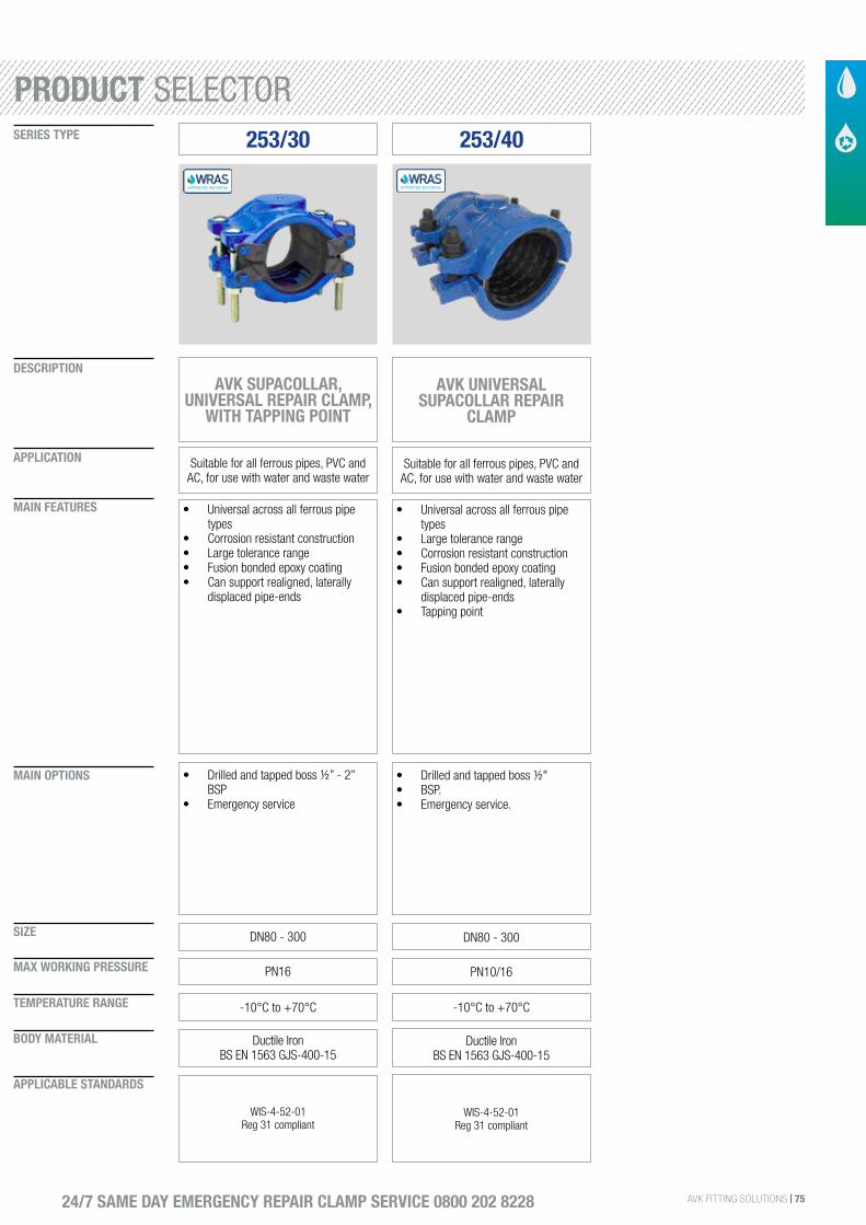
AVK FITTING SOLUTIONS | 75
SIZE
DESCRIPTION
SERIES TYPE
APPLICATION
MAIN FEATURES
MAIN OPTIONS
MAX WORKING PRESSURE
TEMPERATURE RANGE
BODY MATERIAL
APPLICABLE STANDARDS
24/7 SAME DAY EMERGENCY REPAIR CLAMP SERVICE 0800 202 8228
253/30
AVK SUPACOLLAR, UNIVERSAL REPAIR CLAMP,
WITH TAPPING POINT
Suitable for all ferrous pipes, PVC and AC, for use with water and waste water
• Universal across all ferrous pipe types
• Corrosion resistant construction• Large tolerance range• Fusion bonded epoxy coating• Can support realigned, laterally
displaced pipe-ends
DN80 - 300
• Drilled and tapped boss ½” - 2” BSP
• Emergency service
PN16
-10°C to +70°C
Ductile Iron BS EN 1563 GJS-400-15
WIS-4-52-01Reg 31 compliant
AVK UNIVERSAL SUPACOLLAR REPAIR
CLAMP
Suitable for all ferrous pipes, PVC and AC, for use with water and waste water
• Universal across all ferrous pipe types
• Large tolerance range• Corrosion resistant construction• Fusion bonded epoxy coating• Can support realigned, laterally
displaced pipe-ends• Tapping point
DN80 - 300
• Drilled and tapped boss ½"• BSP.• Emergency service.
PN10/16
-10°C to +70°C
Ductile Iron BS EN 1563 GJS-400-15
WIS-4-52-01Reg 31 compliant
253/40
PRODUCT SELECTOR
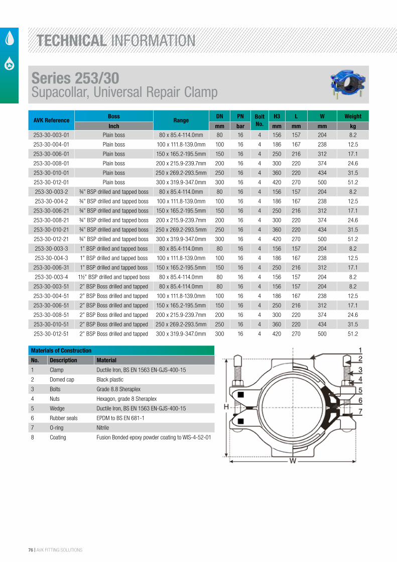
76 | AVK FITTING SOLUTIONS
AVK ReferenceBoss
RangeDN PN Bolt
No.H3 L W Weight
Inch mm bar mm mm mm kg253-30-003-01 Plain boss 80 x 85.4-114.0mm 80 16 4 156 157 204 8.2
253-30-004-01 Plain boss 100 x 111.8-139.0mm 100 16 4 186 167 238 12.5
253-30-006-01 Plain boss 150 x 165.2-195.5mm 150 16 4 250 216 312 17.1
253-30-008-01 Plain boss 200 x 215.9-239.7mm 200 16 4 300 220 374 24.6
253-30-010-01 Plain boss 250 x 269.2-293.5mm 250 16 4 360 220 434 31.5
253-30-012-01 Plain boss 300 x 319.9-347.0mm 300 16 4 420 270 500 51.2
253-30-003-2 ¾” BSP drilled and tapped boss 80 x 85.4-114.0mm 80 16 4 156 157 204 8.2
253-30-004-2 ¾” BSP drilled and tapped boss 100 x 111.8-139.0mm 100 16 4 186 167 238 12.5
253-30-006-21 ¾” BSP drilled and tapped boss 150 x 165.2-195.5mm 150 16 4 250 216 312 17.1
253-30-008-21 ¾” BSP drilled and tapped boss 200 x 215.9-239.7mm 200 16 4 300 220 374 24.6
253-30-010-21 ¾” BSP drilled and tapped boss 250 x 269.2-293.5mm 250 16 4 360 220 434 31.5
253-30-012-21 ¾” BSP drilled and tapped boss 300 x 319.9-347.0mm 300 16 4 420 270 500 51.2
253-30-003-3 1” BSP drilled and tapped boss 80 x 85.4-114.0mm 80 16 4 156 157 204 8.2
253-30-004-3 1” BSP drilled and tapped boss 100 x 111.8-139.0mm 100 16 4 186 167 238 12.5
253-30-006-31 1” BSP drilled and tapped boss 150 x 165.2-195.5mm 150 16 4 250 216 312 17.1
253-30-003-4 1½” BSP drilled and tapped boss 80 x 85.4-114.0mm 80 16 4 156 157 204 8.2
253-30-003-51 2” BSP Boss drilled and tapped 80 x 85.4-114.0mm 80 16 4 156 157 204 8.2
253-30-004-51 2” BSP Boss drilled and tapped 100 x 111.8-139.0mm 100 16 4 186 167 238 12.5
253-30-006-51 2” BSP Boss drilled and tapped 150 x 165.2-195.5mm 150 16 4 250 216 312 17.1
253-30-008-51 2” BSP Boss drilled and tapped 200 x 215.9-239.7mm 200 16 4 300 220 374 24.6
253-30-010-51 2” BSP Boss drilled and tapped 250 x 269.2-293.5mm 250 16 4 360 220 434 31.5
253-30-012-51 2” BSP Boss drilled and tapped 300 x 319.9-347.0mm 300 16 4 420 270 500 51.2
Materials of Construction
No. Description Material
1 Clamp Ductile Iron, BS EN 1563 EN-GJS-400-15
2 Domed cap Black plastic
3 Bolts Grade 8.8 Sheraplex
4 Nuts Hexagon, grade 8 Sheraplex
5 Wedge Ductile Iron, BS EN 1563 EN-GJS-400-15
6 Rubber seals EPDM to BS EN 681-1
7 O-ring Nitrile
8 Coating Fusion Bonded epoxy powder coating to WIS-4-52-01
Series 253/30Supacollar, Universal Repair Clamp
TECHNICAL INFORMATION
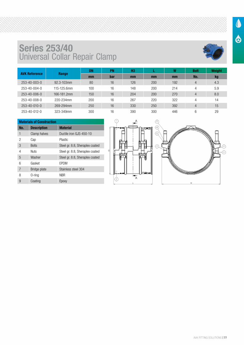
AVK FITTING SOLUTIONS | 77
AVK Reference RangeDN PN H3 L W Bolt Weight
mm bar mm mm mm No. kg
253-40-003-0 92.3-103mm 80 16 126 200 192 4 4.3
253-40-004-0 115-125.6mm 100 16 148 200 214 4 5.9
253-40-006-0 166-181.2mm 150 16 204 200 270 4 8.0
253-40-008-0 220-234mm 200 16 267 220 322 4 14
253-40-010-0 269-294mm 250 16 330 250 392 4 15
253-40-012-0 323-349mm 300 16 390 300 446 6 29
Materials of Construction
No. Description Material
1 Clamp halves Ductile iron GJS-450-10
2 Cap Plastic
3 Bolts Steel gr. 8.8, Sheraplex coated
4 Nuts Steel gr. 8.8, Sheraplex coated
5 Washer Steel gr. 8.8, Sheraplex coated
6 Gasket EPDM
7 Bridge plate Stainless steel 304
8 O-ring NBR
9 Coating Epoxy
Series 253/40Universal Collar Repair Clamp
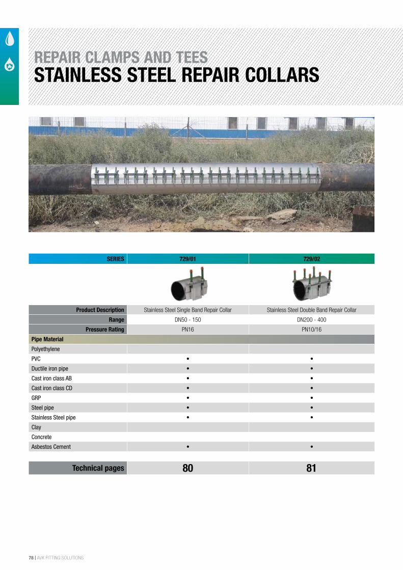
78 | AVK FITTING SOLUTIONS
REPAIR CLAMPS AND TEESSTAINLESS STEEL REPAIR COLLARS
SERIES 729/01 729/02
Product Description Stainless Steel Single Band Repair Collar Stainless Steel Double Band Repair Collar
Range DN50 - 150 DN200 - 400
Pressure Rating PN16 PN10/16
Pipe Material
Polyethylene
PVC • •
Ductile iron pipe • •
Cast iron class AB • •
Cast iron class CD • •
GRP • •
Steel pipe • •
Stainless Steel pipe • •
Clay
Concrete
Asbestos Cement • •
Technical pages 80 81
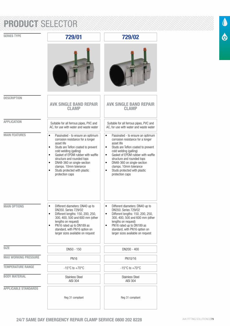
AVK FITTING SOLUTIONS | 79
SIZE
DESCRIPTION
SERIES TYPE
APPLICATION
MAIN FEATURES
MAIN OPTIONS
MAX WORKING PRESSURE
TEMPERATURE RANGE
BODY MATERIAL
APPLICABLE STANDARDS
24/7 SAME DAY EMERGENCY REPAIR CLAMP SERVICE 0800 202 8228
• Passivated - to ensure an optimum corrosion resistance for a longer asset life
• Studs are Teflon coated to prevent cold welding (galling)
• Gasket of EPDM rubber with waffle structure and rounded tops
• DN48-360 on single-section clamps. 10mm tolerance
• Studs protected with plastic protection caps
DN50 - 150 DN200 - 400
• Different diameters: DN40 up to DN350. Series 729/02
• Different lengths: 150, 200, 250, 300, 400, 500 and 600 mm (other lengths on request)
• PN16 rated up to DN189 as standard, with PN16 option on larger sizes available on request
• Different diameters: DN40 up to DN350. Series 729/02
• Different lengths: 150, 200, 250, 300, 400, 500 and 600 mm (other lengths on request)
• PN16 rated up to DN189 as standard, with PN16 option on larger sizes available on request
PN16 PN10/16
-15°C to +70°C -15°C to +70°C
Stainless Steel AISI 304
Stainless Steel AISI 304
Reg 31 compliant Reg 31 compliant
729/01 729/02
AVK SINGLE BAND REPAIR CLAMP
AVK SINGLE BAND REPAIR CLAMP
Suitable for all ferrous pipes, PVC and AC, for use with water and waste water
Suitable for all ferrous pipes, PVC and AC, for use with water and waste water
PRODUCT SELECTOR
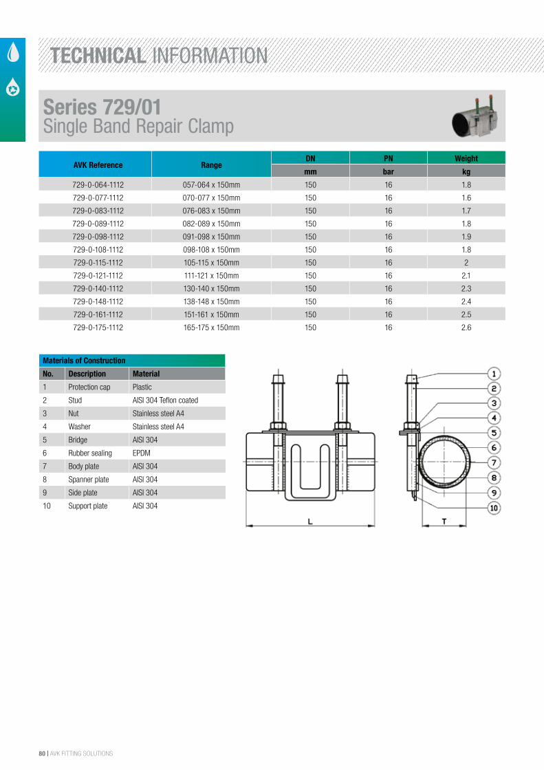
80 | AVK FITTING SOLUTIONS
AVK Reference RangeDN PN Weight
mm bar kg
729-0-064-1112 057-064 x 150mm 150 16 1.8
729-0-077-1112 070-077 x 150mm 150 16 1.6
729-0-083-1112 076-083 x 150mm 150 16 1.7
729-0-089-1112 082-089 x 150mm 150 16 1.8
729-0-098-1112 091-098 x 150mm 150 16 1.9
729-0-108-1112 098-108 x 150mm 150 16 1.8
729-0-115-1112 105-115 x 150mm 150 16 2
729-0-121-1112 111-121 x 150mm 150 16 2.1
729-0-140-1112 130-140 x 150mm 150 16 2.3
729-0-148-1112 138-148 x 150mm 150 16 2.4
729-0-161-1112 151-161 x 150mm 150 16 2.5
729-0-175-1112 165-175 x 150mm 150 16 2.6
Materials of Construction
No. Description Material
1 Protection cap Plastic
2 Stud AISI 304 Teflon coated
3 Nut Stainless steel A4
4 Washer Stainless steel A4
5 Bridge AISI 304
6 Rubber sealing EPDM
7 Body plate AISI 304
8 Spanner plate AISI 304
9 Side plate AISI 304
10 Support plate AISI 304
Series 729/01Single Band Repair Clamp
TECHNICAL INFORMATION
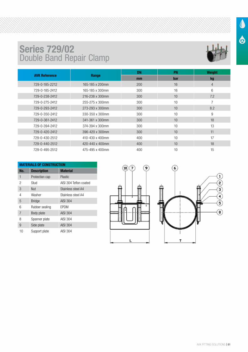
AVK FITTING SOLUTIONS | 81
AVK Reference RangeDN PN Weight
mm bar kg
729-0-185-2212 165-185 x 200mm 200 16 4
729-0-185-2412 165-185 x 300mm 300 16 6
729-0-238-2412 216-238 x 300mm 300 10 7.2
729-0-275-2412 255-275 x 300mm 300 10 7
729-0-293-2412 273-293 x 300mm 300 10 8.2
729-0-350-2412 330-350 x 300mm 300 10 9
729-0-361-2412 341-361 x 300mm 300 10 18
729-0-394-2412 374-394 x 300mm 300 10 13
729-0-420-2412 396-420 x 300mm 300 10 11
729-0-430-2512 410-430 x 400mm 400 10 17
729-0-440-2512 420-440 x 400mm 400 10 18
729-0-495-2512 475-495 x 400mm 400 10 15
MATERIALS OF CONSTRUCTION
No. Description Material
1 Protection cap Plastic
2 Stud AISI 304 Teflon coated
3 Nut Stainless steel A4
4 Washer Stainless steel A4
5 Bridge AISI 304
6 Rubber sealing EPDM
7 Body plate AISI 304
8 Spanner plate AISI 304
9 Side plate AISI 304
10 Support plate AISI 304
Series 729/02Double Band Repair Clamp
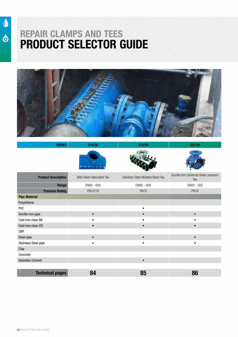
82 | AVK FITTING SOLUTIONS
SERIES 214/30 215/30 257/30
Product Description Mild Steel Fabricated Tee Stainless Steel Multiple Band TeeDuctile Iron Universal Under pressure
Tee
Range DN80 - 600 DN80 - 600 DN80 - 300
Pressure Rating PN10/16 PN10 PN16
Pipe Material
Polyethlene
PVC •
Ductile iron pipe • • •
Cast iron class AB • • •
Cast iron class CD • • •
GRP
Steel pipe • • •
Stainless Steel pipe • • •
Clay
Concrete
Asbestos Cement •
Technical pages 84 85 86
REPAIR CLAMPS AND TEESPRODUCT SELECTOR GUIDE
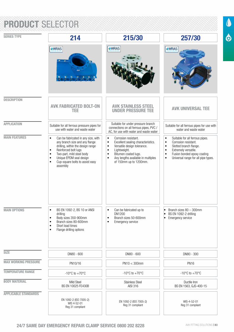
AVK FITTING SOLUTIONS | 83
SIZE
DESCRIPTION
SERIES TYPE
APPLICATION
MAIN FEATURES
MAIN OPTIONS
MAX WORKING PRESSURE
TEMPERATURE RANGE
BODY MATERIAL
APPLICABLE STANDARDS
24/7 SAME DAY EMERGENCY REPAIR CLAMP SERVICE 0800 202 8228
214
AVK FABRICATED BOLT-ON TEE
Suitable for all ferrous pressure pipes for use with water and waste water
• Can be fabricated in any size, with any branch size and any flange drilling, within the design range
• Reinforced bolt lugs• Two-part, mild steel body• Unique EPDM seal design• Cup-square bolts to assist easy
assembly
DN80 - 600
• BS EN 1092-2, BS 10 or ANSI drilling
• Body sizes 350-900mm• Branch sizes 80-600mm• Short lead times• Flange drilling options
PN10/16
-10°C to +70°C
Mild SteelBS EN 10025 FE430B
EN 1092-2 (ISO 7005-2)WIS 4-52-01
Reg 31 compliant
215/30 257/30
AVK STAINLESS STEEL UNDER PRESSURE TEE
Suitable for under pressure branch connections on all ferrous pipes, PVC / AC, for use with water and waste water
• Corrosion resistant.• Excellent sealing characteristics.• Versatile design tolerance.• Lightweight.• Bitumen coated lugs.• Any lengths available in multiples
of 150mm up to 1200mm.
DN80 - 600
• Can be fabricated up to DN1200
• Branch sizes 50-600mm• Emergency service
PN10 < 300mm
-10°C to +70°C
Stainless Steel AISI 316
EN 1092-2 (ISO 7005-2)Reg 31 compliant
AVK UNIVERSAL TEE
Suitable for all ferrous pipes for use with water and waste water
• Suitable for all ferrous pipes.• Corrosion resistant. • Slotted branch flange.• Extremely versatile.• Fusion bonded epoxy coating• Universal range for all pipe types.
DN80 - 300
• Branch sizes 80 – 300mm• BS EN 1092-2 drilling• Emergency service
PN16
-10°C to +70°C
Ductile IronBS EN 1563, GJS-400-15
WIS-4-52-01Reg 31 compliant
PRODUCT SELECTOR
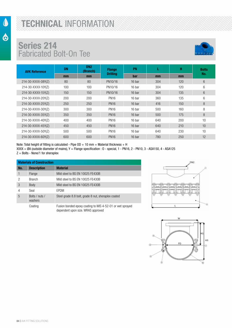
84 | AVK FITTING SOLUTIONS
AVK ReferenceDN
DN2 (Branch) Flange
DrillingPN L H Bolts
No.mm mm bar mm mm
214-30-XXXX-08Y(Z) 80 80 PN10/16 16 bar 304 120 6
214-30-XXXX-10Y(Z) 100 100 PN10/16 16 bar 304 120 6
214-30-XXXX-15Y(Z) 150 150 PN10/16 16 bar 304 135 6
214-30-XXXX-20Y(Z) 200 200 PN16 16 bar 360 135 6
214-30-XXXX-25Y(Z) 250 250 PN16 16 bar 416 150 8
214-30-XXXX-30Y(Z) 300 300 PN16 16 bar 500 160 8
214-30-XXXX-35Y(Z) 350 350 PN16 16 bar 500 175 8
214-30-XXXX-40Y(Z) 400 400 PN16 16 bar 640 200 10
214-30-XXXX-45Y(Z) 450 450 PN16 16 bar 640 210 10
214-30-XXXX-50Y(Z) 500 500 PN16 16 bar 640 230 10
214-30-XXXX-60Y(Z) 600 600 PN16 16 bar 780 250 12
Materials of Construction
No. Description Material
1 Flange Mild steel to BS EN 10025 FE430B
2 Branch Mild steel to BS EN 10025 FE430B
3 Body Mild steel to BS EN 10025 FE430B
4 Seal EPDM
5 Bolts / nuts / washers
Steel grade 8.8 bolt, grade 8 nut, sheraplex coated
Coating Fusion bonded epoxy coating to WIS 4-52-01 or wet sprayed dependent upon size. WRAS approved
Note: Total height of fitting is calculated - Pipe OD + 10 mm + Material thickness + HXXXX = ØA (outside diameter of mains), Y = Flange specification : O - special, 1 - PN16, 2 - PN10, 3 - ASA150, 4 - ASA125Z = Bolts - None/1 for sheraplex
Series 214Fabricated Bolt-On Tee
TECHNICAL INFORMATION
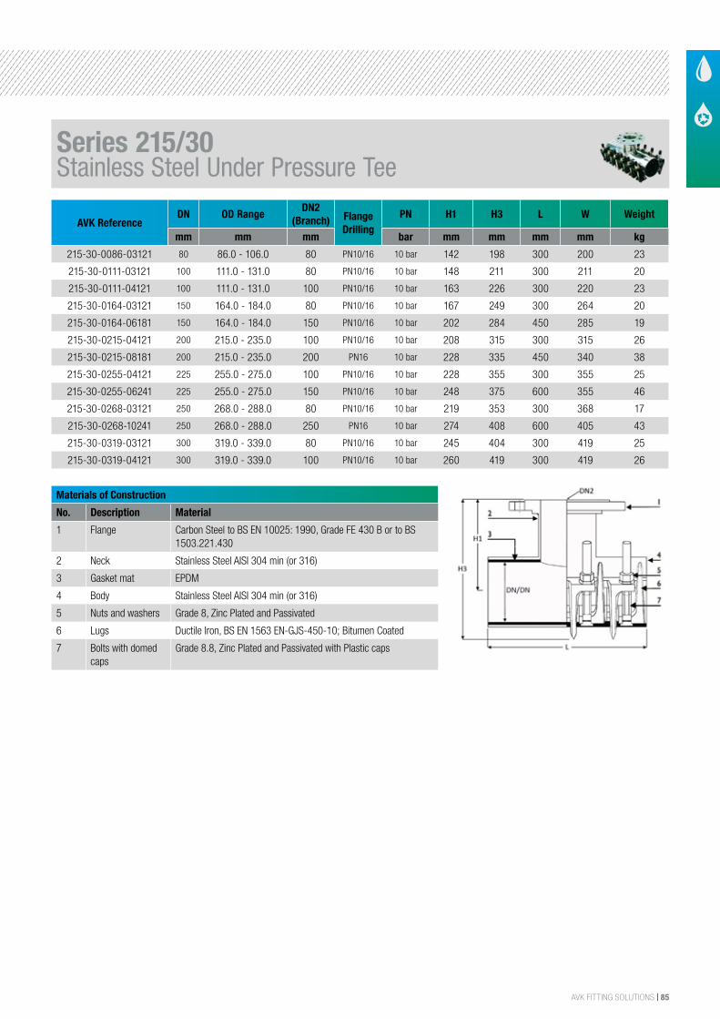
AVK FITTING SOLUTIONS | 85
AVK ReferenceDN OD Range
DN2(Branch) Flange
DrillingPN H1 H3 L W Weight
mm mm mm bar mm mm mm mm kg
215-30-0086-03121 80 86.0 - 106.0 80 PN10/16 10 bar 142 198 300 200 23
215-30-0111-03121 100 111.0 - 131.0 80 PN10/16 10 bar 148 211 300 211 20
215-30-0111-04121 100 111.0 - 131.0 100 PN10/16 10 bar 163 226 300 220 23
215-30-0164-03121 150 164.0 - 184.0 80 PN10/16 10 bar 167 249 300 264 20
215-30-0164-06181 150 164.0 - 184.0 150 PN10/16 10 bar 202 284 450 285 19
215-30-0215-04121 200 215.0 - 235.0 100 PN10/16 10 bar 208 315 300 315 26
215-30-0215-08181 200 215.0 - 235.0 200 PN16 10 bar 228 335 450 340 38
215-30-0255-04121 225 255.0 - 275.0 100 PN10/16 10 bar 228 355 300 355 25
215-30-0255-06241 225 255.0 - 275.0 150 PN10/16 10 bar 248 375 600 355 46
215-30-0268-03121 250 268.0 - 288.0 80 PN10/16 10 bar 219 353 300 368 17
215-30-0268-10241 250 268.0 - 288.0 250 PN16 10 bar 274 408 600 405 43
215-30-0319-03121 300 319.0 - 339.0 80 PN10/16 10 bar 245 404 300 419 25
215-30-0319-04121 300 319.0 - 339.0 100 PN10/16 10 bar 260 419 300 419 26
Materials of Construction
No. Description Material
1 Flange Carbon Steel to BS EN 10025: 1990, Grade FE 430 B or to BS 1503.221.430
2 Neck Stainless Steel AISI 304 min (or 316)
3 Gasket mat EPDM
4 Body Stainless Steel AISI 304 min (or 316)
5 Nuts and washers Grade 8, Zinc Plated and Passivated
6 Lugs Ductile Iron, BS EN 1563 EN-GJS-450-10; Bitumen Coated
7 Bolts with domed caps
Grade 8.8, Zinc Plated and Passivated with Plastic caps
Series 215/30Stainless Steel Under Pressure Tee
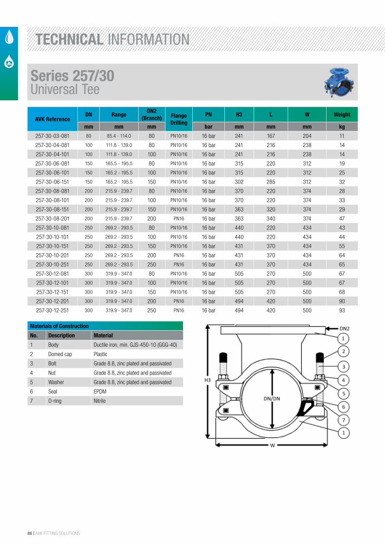
86 | AVK FITTING SOLUTIONS
AVK ReferenceDN Range
DN2(Branch) Flange
DrillingPN H3 L W Weight
mm mm mm bar mm mm mm kg
257-30-03-081 80 85.4 - 114.0 80 PN10/16 16 bar 241 167 204 11
257-30-04-081 100 111.8 - 139.0 80 PN10/16 16 bar 241 216 238 14
257-30-04-101 100 111.8 - 139.0 100 PN10/16 16 bar 241 216 238 14
257-30-06-081 150 165.5 - 195.5 80 PN10/16 16 bar 315 220 312 19
257-30-06-101 150 165.2 - 195.5 100 PN10/16 16 bar 315 220 312 25
257-30-06-151 150 165.2 - 195.5 150 PN10/16 16 bar 302 285 312 32
257-30-08-081 200 215.9 - 239.7 80 PN10/16 16 bar 370 220 374 28
257-30-08-101 200 215.9 - 239.7 100 PN10/16 16 bar 370 220 374 33
257-30-08-151 200 215.9 - 239.7 150 PN10/16 16 bar 363 320 374 29
257-30-08-201 200 215.9 - 239.7 200 PN16 16 bar 363 340 374 47
257-30-10-081 250 269.2 - 293.5 80 PN10/16 16 bar 440 220 434 43
257-30-10-101 250 269.2 - 293.5 100 PN10/16 16 bar 440 220 434 44
257-30-10-151 250 269.2 - 293.5 150 PN10/16 16 bar 431 370 434 55
257-30-10-201 250 269.2 - 293.5 200 PN16 16 bar 431 370 434 64
257-30-10-251 250 269.2 - 293.5 250 PN16 16 bar 431 370 434 65
257-30-12-081 300 319.9 - 347.0 80 PN10/16 16 bar 505 270 500 67
257-30-12-101 300 319.9 - 347.0 100 PN10/16 16 bar 505 270 500 67
257-30-12-151 300 319.9 - 347.0 150 PN10/16 16 bar 505 270 500 68
257-30-12-201 300 319.9 - 347.0 200 PN16 16 bar 494 420 500 90
257-30-12-251 300 319.9 - 347.0 250 PN16 16 bar 494 420 500 93
Materials of Construction
No. Description Material
1 Body Ductile iron, min. GJS-450-10 (GGG-40)
2 Domed cap Plastic
3 Bolt Grade 8.8, zinc plated and passivated
4 Nut Grade 8.8, zinc plated and passivated
5 Washer Grade 8.8, zinc plated and passivated
6 Seal EPDM
7 O-ring Nitrile
Series 257/30Universal Tee
TECHNICAL INFORMATION
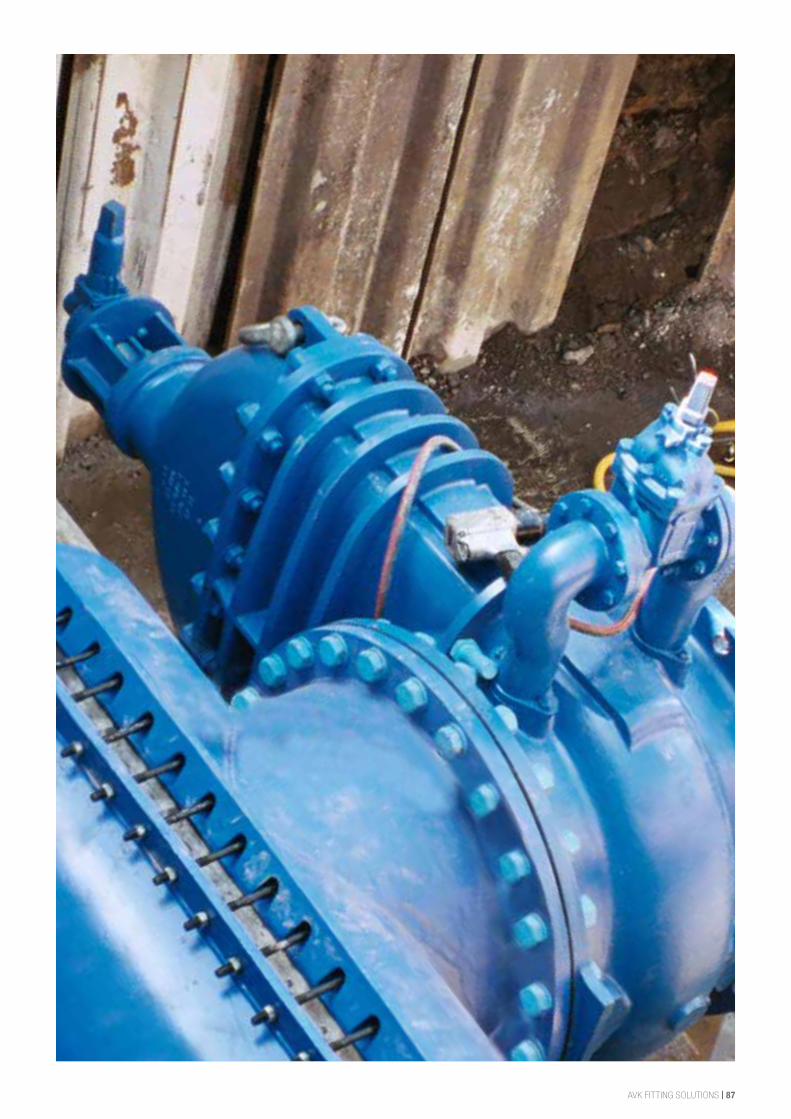
AVK FITTING SOLUTIONS | 87
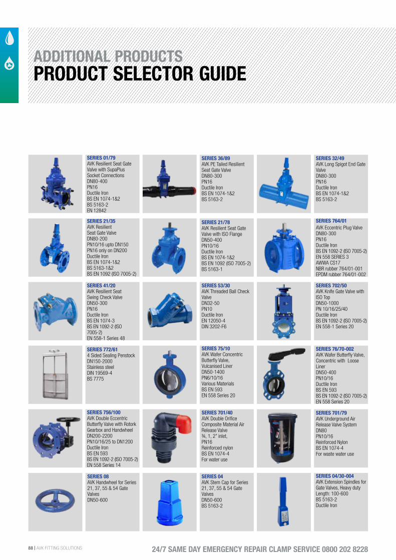
88 | AVK FITTING SOLUTIONS 24/7 SAME DAY EMERGENCY REPAIR CLAMP SERVICE 0800 202 8228
SERIES 21/35AVK ResilientSeat Gate ValveDN80-200PN10/16 upto DN150PN16 only on DN200Ductile Iron BS EN 1074-1&2BS 5163-1&2BS EN 1092 (ISO 7005-2)
SERIES 36/89AVK PE Tailed Resilient Seat Gate ValveDN80-300PN16Ductile IronBS EN 1074-1&2BS 5163-2
SERIES 32/49AVK Long Spigot End Gate ValveDN80-300PN16Ductile IronBS EN 1074-1&2BS 5163-2
SERIES 764/01AVK Eccentric Plug ValveDN80-300PN16Ductile IronBS EN 1092-2 (ISO 7005-2)EN 558 SERIES 3AWWA CS17NBR rubber 764/01-001EPDM rubber 764/01-002
SERIES 21/78AVK Resilient Seat Gate Valve with ISO FlangeDN50-400 PN10/16 Ductile IronBS EN 1074-1&2BS EN 1092 (ISO 7005-2) BS 5163-1
SERIES 01/79AVK Resilient Seat Gate Valve with SupaPlus Socket ConnectionsDN80-400PN16Ductile IronBS EN 1074-1&2BS 5163-2EN 12842
SERIES 41/20AVK Resilient Seat Swing Check ValveDN50-300PN16Ductile IronBS EN 1074-3BS EN 1092-2 (ISO 7005-2)EN 558-1 Series 48
SERIES 53/30AVK Threaded Ball Check ValveDN32-50PN10 Ductile IronEN 12050-4DIN 3202-F6
SERIES 75/10AVK Wafer Concentric Butterfly Valve,Vulcanised LinerDN50-1400PN6/10/16Various MaterialsBS EN 593EN 558 Series 20
SERIES 772/614 Sided Sealing PenstockDN150-2000Stainless steelDIN 19569-4BS 7775
SERIES 702/50AVK Knife Gate Valve with ISO TopDN50-1000 PN 10/16/25/40Ductile IronBS EN 1092-2 (ISO 7005-2)EN 558-1 Series 20
SERIES 756/100AVK Double Eccentric Butterfly Valve with Rotork Gearbox and HandwheelDN200-2200 PN10/16/25 to DN1200Ductile Iron BS EN 593BS EN 1092-2 (ISO 7005-2)EN 558 Series 14
SERIES 76/70-002AVK Wafer Butterfly Valve, Concentric with Loose LinerDN50-400 PN10/16Ductile IronBS EN 593BS EN 1092-2 (ISO 7005-2)EN 558 Series 20
SERIES 701/40AVK Double Orifice Composite Material Air Release Valve¾, 1, 2” inlet,PN16Reinforced nylonBS EN 1074-4For water use
SERIES 701/79AVK Underground Air Release Valve SystemDN80PN10/16Reinforced NylonBS EN 1074-4For waste water use
SERIES 04AVK Stem Cap for Series 21, 37, 55 & 54 Gate ValvesDN50-600BS 5163-2
SERIES 04/30-004AVK Extension Spindles for Gate Valves, Heavy dutyLength: 100-600BS 5163-2Ductile Iron
SERIES 08AVK Handwheel for Series 21, 37, 55 & 54 Gate ValvesDN50-600
ADDITIONAL PRODUCTSPRODUCT SELECTOR GUIDE
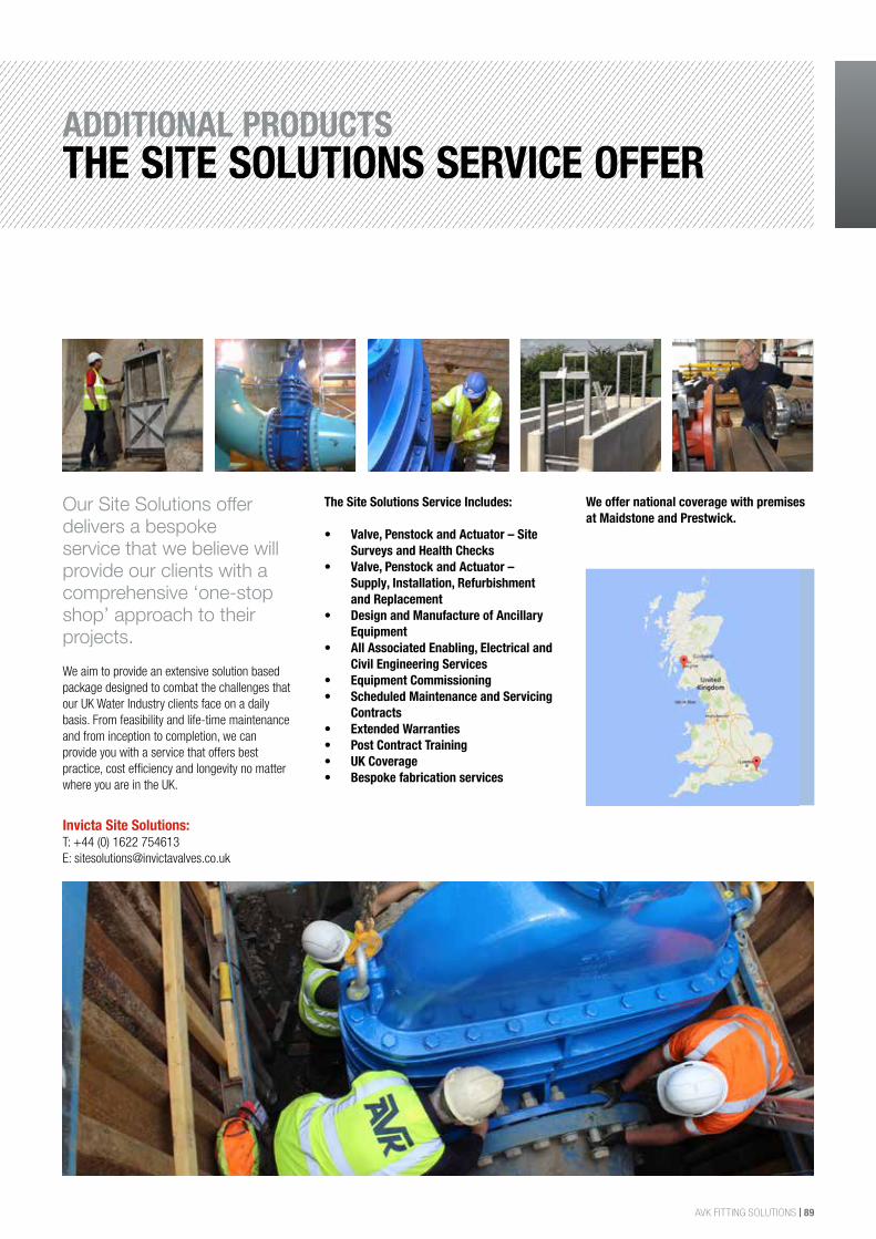
AVK FITTING SOLUTIONS | 89
ADDITIONAL PRODUCTSTHE SITE SOLUTIONS SERVICE OFFER
Our Site Solutions offer delivers a bespoke service that we believe will provide our clients with a comprehensive ‘one-stop shop’ approach to their projects. We aim to provide an extensive solution based package designed to combat the challenges that our UK Water Industry clients face on a daily basis. From feasibility and life-time maintenance and from inception to completion, we can provide you with a service that offers best practice, cost efficiency and longevity no matter where you are in the UK.
The Site Solutions Service Includes: • Valve, Penstock and Actuator – Site
Surveys and Health Checks• Valve, Penstock and Actuator –
Supply, Installation, Refurbishment and Replacement
• Design and Manufacture of Ancillary Equipment
• All Associated Enabling, Electrical and Civil Engineering Services
• Equipment Commissioning • Scheduled Maintenance and Servicing
Contracts • Extended Warranties• Post Contract Training • UK Coverage • Bespoke fabrication services
We offer national coverage with premises at Maidstone and Prestwick.
Invicta Site Solutions: T: +44 (0) 1622 754613E: [email protected]
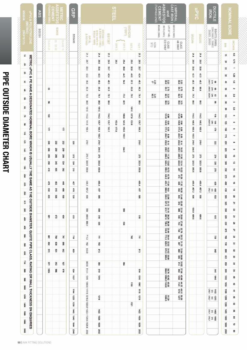
90 | AVK FITTING SOLUTIONS
PIPE OUTSIDE DIAMETER CHARTw
ww
.avkuk.co.uk
PIPE OUTSIDE DIAMETER CHART
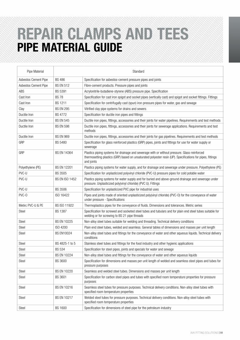
AVK FITTING SOLUTIONS | 91
REPAIR CLAMPS AND TEESPIPE MATERIAL GUIDE
Pipe Material Standard
Asbestos Cement Pipe BS 486 Specification for asbestos-cement pressure pipes and joints
Asbestos Cement Pipe BS EN 512 Fibre-cement products. Pressure pipes and joints
ABS BS 5391 Acrylonitrile-butadiene-styrene (ABS) pressure pipe. Specification
Cast Iron BS 78 Specification for cast iron spigot and socket pipes (vertically cast) and spigot and socket fittings. Fittings
Cast Iron BS 1211 Specification for centrifugally cast (spun) iron pressure pipes for water, gas and sewage
Clay BS EN 295 Vitrified clay pipe systems for drains and sewers
Ductile Iron BS 4772 Specification for ductile iron pipes and fittings
Ductile Iron BS EN 545 Ductile iron pipes, fittings, accessories and their joints for water pipelines. Requirements and test methods
Ductile Iron BS EN 598 Ductile iron pipes, fittings, accessories and their joints for sewerage applications. Requirements and test methods
Ductile Iron BS EN 969 Ductile iron pipes, fittings, accessories and their joints for gas pipelines. Requirements and test methods
GRP BS 5480 Specification for glass reinforced plastics (GRP) pipes, joints and fittings for use for water supply or sewerage
GRP BS EN 14364 Plastics piping systems for drainage and sewerage with or without pressure. Glass-reinforced thermosetting plastics (GRP) based on unsaturated polyester resin (UP). Specifications for pipes, fittings and joints
Polyethylene (PE) BS EN 12201 Plastics piping systems for water supply, and for drainage and sewerage under pressure. Polyethylene (PE)
PVC-U BS 3505 Specification for unplasticized polyvinyl chloride (PVC-U) pressure pipes for cold potable water
PVC-U BS EN ISO 1452 Plastics piping systems for water supply and for buried and above-ground drainage and sewerage under pressure. Unplasticized poly(vinyl chloride) (PVC U). Fittings
PVC-U BS 3506 Specification for unplasticized PVC pipe for industrial uses
PVC-O ISO 16422 Pipes and joints made of oriented unplasticized poly(vinyl chloride) (PVC-O) for the conveyance of water under pressure - Specifications
Metirc PVC-U & PE BS ISO 11922 Thermoplastics pipes for the conveyance of fluids. Dimensions and tolerances. Metric series
Steel BS 1387 Specification for screwed and socketed steel tubes and tubulars and for plain end steel tubes suitable for welding or for screwing to BS 21 pipe threads
Steel BS EN 10225 Non-alloy steel tubes suitable for welding and threading. Technical delivery conditions
Steel ISO 4200 Plain end steel tubes, welded and seamless. General tables of dimensions and masses per unit length
Steel BS EN10024 Non-alloy steel tubes and fittings for the conveyance of water and other aqueous liquids. Technical delivery conditions
Steel BS 4825-1 to 5 Stainless steel tubes and fittings for the food industry and other hygienic applications
Steel BS 534 Specification for steel pipes, joints and specials for water and sewage
Steel BS EN 10224 Non-alloy steel tubes and fittings for the conveyance of water and other aqueous liquids
Steel BS 3600 Specification for dimensions and masses per unit length of welded and seamless steel pipes and tubes for pressure purposes
Steel BS EN 10220 Seamless and welded steel tubes. Dimensions and masses per unit length
Steel BS 3601 Specification for carbon steel pipes and tubes with specified room temperature properties for pressure purposes
Steel BS EN 10216 Seamless steel tubes for pressure purposes. Technical delivery conditions. Non-alloy steel tubes with specified room temperature properties
Steel BS EN 10217 Welded steel tubes for pressure purposes. Technical delivery conditions. Non-alloy steel tubes with specified room temperature properties
Steel BS 1600 Specification for dimensions of steel pipe for the petroleum industry
Northampton Office8 Rushmills Northampton NN4 7YB England
T: +44 (0) 1604 601188 F: +44 (0) 1604 604818E: [email protected]
www.avkuk.co.uk W&WW 2016 Copyright@AVK Group A/S 2016
Invicta Site Solutions: T: +44 (0) 1622 754613E: [email protected]
Webshophttps://shop.avkuk.co.uk/
AVK FS JAN 2018 Copyright@AVK Group A/S 2018