Embed Size (px)
Citation preview
Auxiliary Views
Chapter 7
2Technical Drawing 13th EditionGiesecke, Mitchell, Spencer, Hill Dygdon, Novak, Lockhart
© 2009 Pearson Education, Upper Saddle River, NJ 07458.
All Rights Reserved.
Objectives
• Create an auxiliary view from orthographic views
• Draw folding lines or reference-plane lines between any two adjacent views
• Construct depth, height, or width auxiliary views
• Plot curves in auxiliary views
3Technical Drawing 13th EditionGiesecke, Mitchell, Spencer, Hill Dygdon, Novak, Lockhart
© 2009 Pearson Education, Upper Saddle River, NJ 07458.
All Rights Reserved.
Objectives (cont.)
• Construct partial auxiliary views• Create auxiliary section views• Produce views to show the true
length of a line, point view of a line, edge view of a surface, and true size view of a surface
4Technical Drawing 13th EditionGiesecke, Mitchell, Spencer, Hill Dygdon, Novak, Lockhart
© 2009 Pearson Education, Upper Saddle River, NJ 07458.
All Rights Reserved.
Objectives (cont.)
• Show the true size of the angle between two planes
• Construct the development of prisms, pyramids, cylinders, and cones
• Use triangulation to transfer surface shapes to a development
• Create the development of transition pieces
5Technical Drawing 13th EditionGiesecke, Mitchell, Spencer, Hill Dygdon, Novak, Lockhart
© 2009 Pearson Education, Upper Saddle River, NJ 07458.
All Rights Reserved.
Objectives (cont.)
• Graphically solve for the intersection of solids
• Apply revolution to show true length edges and true size surfaces
6Technical Drawing 13th EditionGiesecke, Mitchell, Spencer, Hill Dygdon, Novak, Lockhart
© 2009 Pearson Education, Upper Saddle River, NJ 07458.
All Rights Reserved.
Understanding Auxiliary Views• An auxiliary view is an
orthographic view that is not a standard projection
• Auxiliary views allow principal faces of features that are not parallel to the standard planes of projection to appear true shape and size
7Technical Drawing 13th EditionGiesecke, Mitchell, Spencer, Hill Dygdon, Novak, Lockhart
© 2009 Pearson Education, Upper Saddle River, NJ 07458.
All Rights Reserved.
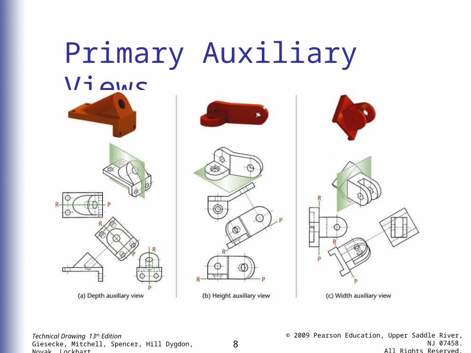
Primary Auxiliary Views
• A primary auxiliary view is projected onto a plane that is perpendicular to one of the principal planes of projection and is inclined to the other two
8Technical Drawing 13th EditionGiesecke, Mitchell, Spencer, Hill Dygdon, Novak, Lockhart
© 2009 Pearson Education, Upper Saddle River, NJ 07458.
All Rights Reserved.
Primary Auxiliary Views
9Technical Drawing 13th EditionGiesecke, Mitchell, Spencer, Hill Dygdon, Novak, Lockhart
© 2009 Pearson Education, Upper Saddle River, NJ 07458.
All Rights Reserved.
Revolving a Drawing
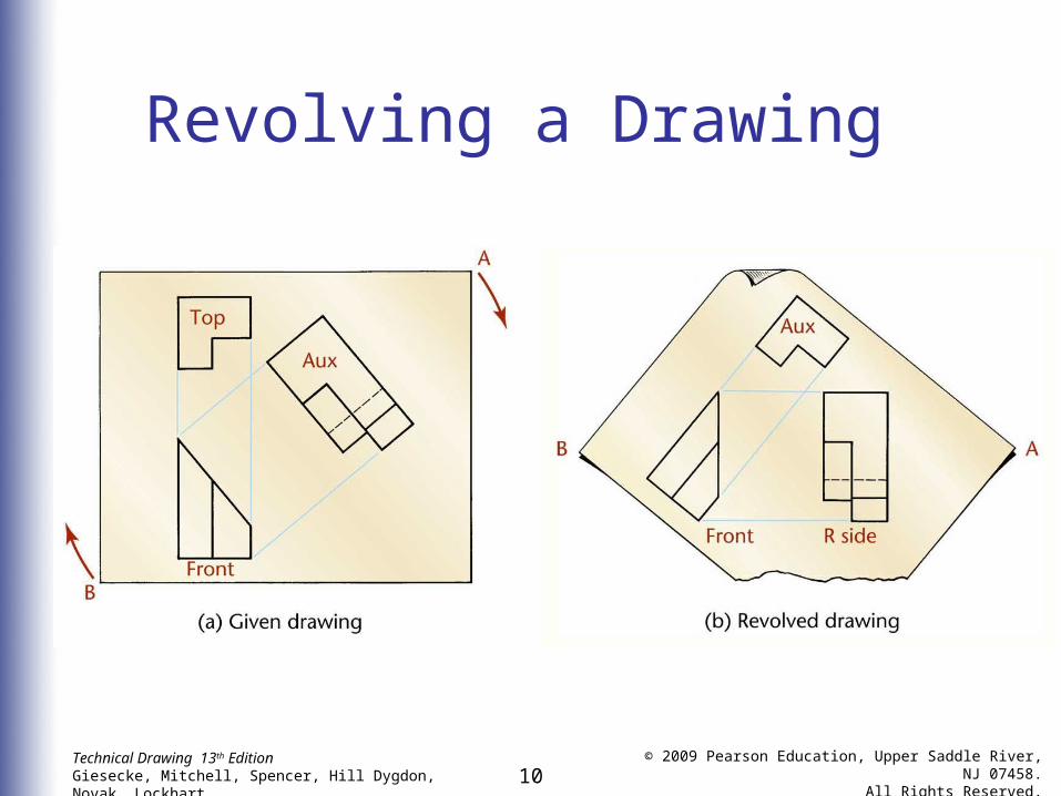
• Some times it is easier to visualize and draw and auxiliary view when revolved to the position of a regular view• It should be understood that an
auxiliary view basically is like any other view
10Technical Drawing 13th EditionGiesecke, Mitchell, Spencer, Hill Dygdon, Novak, Lockhart
© 2009 Pearson Education, Upper Saddle River, NJ 07458.
All Rights Reserved.
Revolving a Drawing
11Technical Drawing 13th EditionGiesecke, Mitchell, Spencer, Hill Dygdon, Novak, Lockhart
© 2009 Pearson Education, Upper Saddle River, NJ 07458.
All Rights Reserved.
Classification of Auxiliary Views• Auxiliary views are named for the
principal dimension shown in the auxiliary view such as:• Depth auxiliary• Height auxiliary• Width auxiliary
12Technical Drawing 13th EditionGiesecke, Mitchell, Spencer, Hill Dygdon, Novak, Lockhart
© 2009 Pearson Education, Upper Saddle River, NJ 07458.
All Rights Reserved.
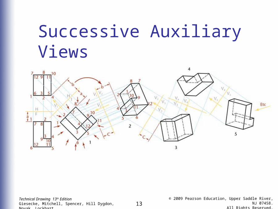
Successive Auxiliary Views
• From primary auxiliary views, a secondary auxiliary view can be drawn
• Third auxiliary views can be projected from secondary views• An infinite number of successive
auxiliary views may be drawn
13Technical Drawing 13th EditionGiesecke, Mitchell, Spencer, Hill Dygdon, Novak, Lockhart
© 2009 Pearson Education, Upper Saddle River, NJ 07458.
All Rights Reserved.
Successive Auxiliary Views
14Technical Drawing 13th EditionGiesecke, Mitchell, Spencer, Hill Dygdon, Novak, Lockhart
© 2009 Pearson Education, Upper Saddle River, NJ 07458.
All Rights Reserved.
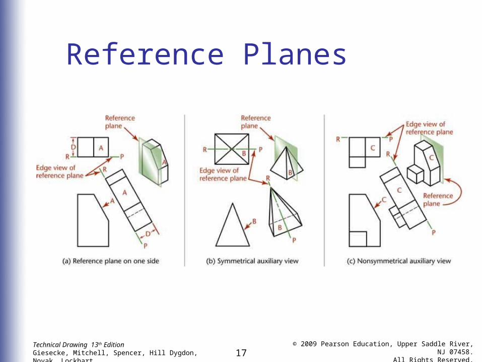
Reference Planes
• Instead of using one of the planes of projection, reference planes parallel to the plane of projection and touching or cutting through the object are used in auxiliary views
• Reference planes should be positioned so it is convenient to transfer distances
15Technical Drawing 13th EditionGiesecke, Mitchell, Spencer, Hill Dygdon, Novak, Lockhart
© 2009 Pearson Education, Upper Saddle River, NJ 07458.
All Rights Reserved.
Reference Planes
• Reference lines, like folding lines, are always at right angles to the projection lines between the views
• A reference plane appears as a line in two alternate views, never in an adjacent view
16Technical Drawing 13th EditionGiesecke, Mitchell, Spencer, Hill Dygdon, Novak, Lockhart
© 2009 Pearson Education, Upper Saddle River, NJ 07458.
All Rights Reserved.
Reference Planes
• Measurements are always made at right angles to the reference lines or parallel to the projection lines
• In the auxiliary view, all points are at the same distances from the reference line as the corresponding points are from the reference line in the alternate view, or the second previous view
17Technical Drawing 13th EditionGiesecke, Mitchell, Spencer, Hill Dygdon, Novak, Lockhart
© 2009 Pearson Education, Upper Saddle River, NJ 07458.
All Rights Reserved.
Reference Planes
18Technical Drawing 13th EditionGiesecke, Mitchell, Spencer, Hill Dygdon, Novak, Lockhart
© 2009 Pearson Education, Upper Saddle River, NJ 07458.
All Rights Reserved.
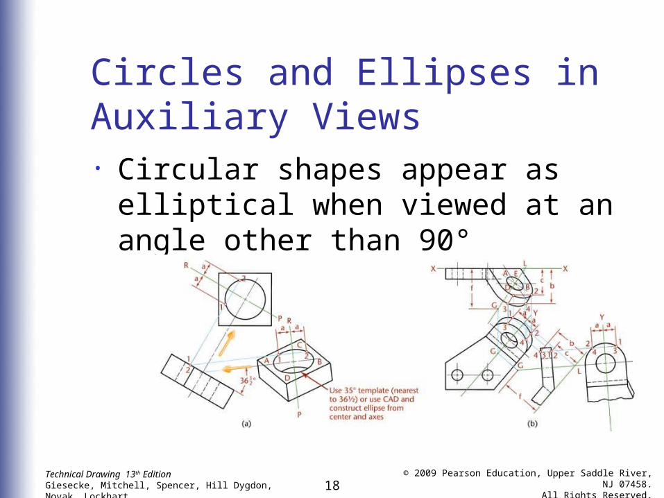
Circles and Ellipses in Auxiliary Views• Circular shapes appear as elliptical
when viewed at an angle other than 90°
19Technical Drawing 13th EditionGiesecke, Mitchell, Spencer, Hill Dygdon, Novak, Lockhart
© 2009 Pearson Education, Upper Saddle River, NJ 07458.
All Rights Reserved.
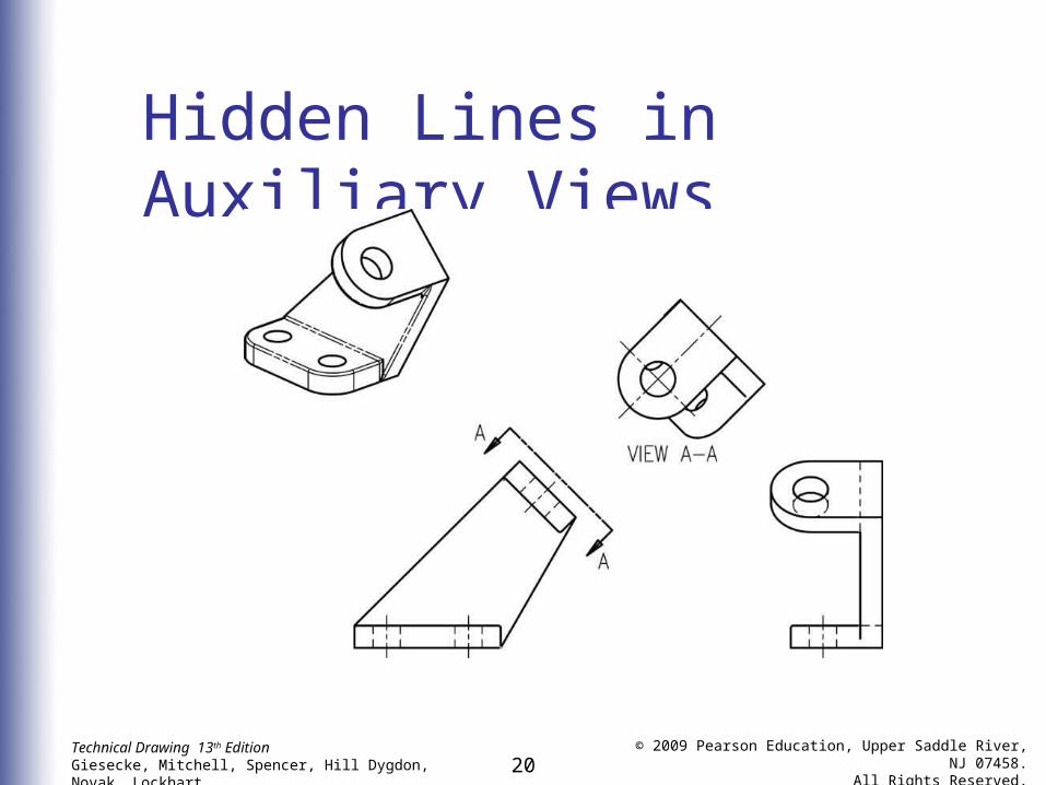
Hidden Lines in Auxiliary Views• Generally hidden lines should be
omitted in auxiliary views unless they are needed to clearly communicate the drawing’s intent
20Technical Drawing 13th EditionGiesecke, Mitchell, Spencer, Hill Dygdon, Novak, Lockhart
© 2009 Pearson Education, Upper Saddle River, NJ 07458.
All Rights Reserved.
Hidden Lines in Auxiliary Views
21Technical Drawing 13th EditionGiesecke, Mitchell, Spencer, Hill Dygdon, Novak, Lockhart
© 2009 Pearson Education, Upper Saddle River, NJ 07458.
All Rights Reserved.
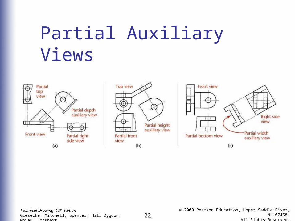
Partial Auxiliary Views
• Partial auxiliary views are often sufficient to convey information and may be easier to read• Usually a break line is used to
indicate the imaginary break in the views
22Technical Drawing 13th EditionGiesecke, Mitchell, Spencer, Hill Dygdon, Novak, Lockhart
© 2009 Pearson Education, Upper Saddle River, NJ 07458.
All Rights Reserved.
Partial Auxiliary Views
23Technical Drawing 13th EditionGiesecke, Mitchell, Spencer, Hill Dygdon, Novak, Lockhart
© 2009 Pearson Education, Upper Saddle River, NJ 07458.
All Rights Reserved.
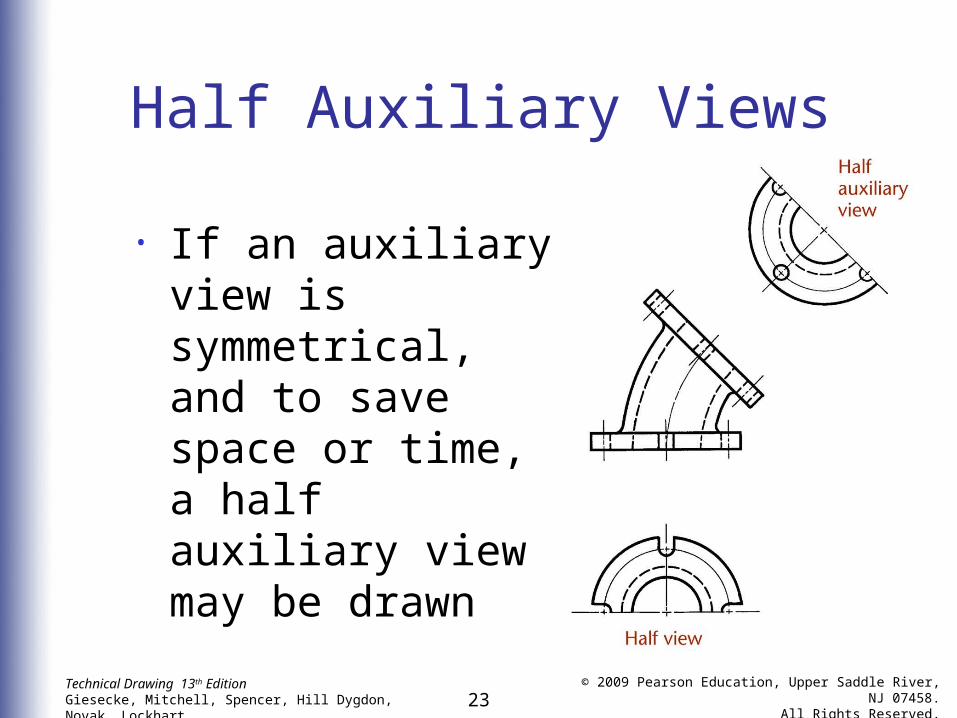
Half Auxiliary Views
• If an auxiliary view is symmetrical, and to save space or time, a half auxiliary view may be drawn
24Technical Drawing 13th EditionGiesecke, Mitchell, Spencer, Hill Dygdon, Novak, Lockhart
© 2009 Pearson Education, Upper Saddle River, NJ 07458.
All Rights Reserved.
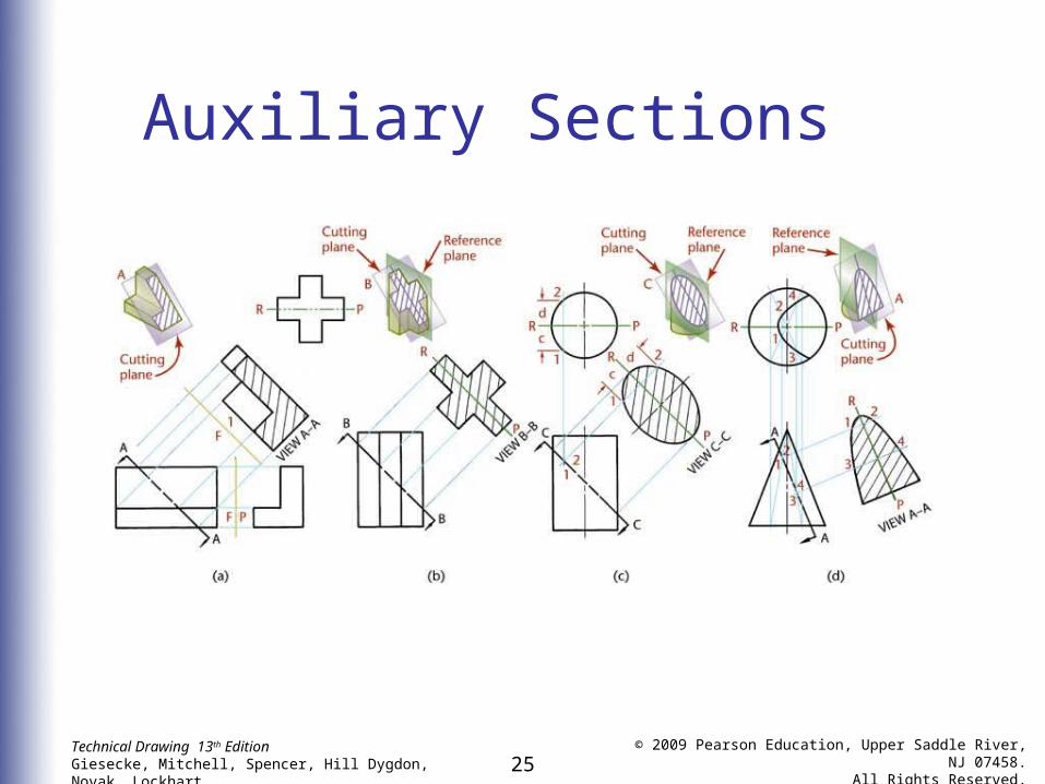
Auxiliary Sections
• An auxiliary section is simply an auxiliary view in section
• The cutting plane line indicates both the location of the cutting plane and the direction of sight for the auxiliary section
25Technical Drawing 13th EditionGiesecke, Mitchell, Spencer, Hill Dygdon, Novak, Lockhart
© 2009 Pearson Education, Upper Saddle River, NJ 07458.
All Rights Reserved.
Auxiliary Sections
26Technical Drawing 13th EditionGiesecke, Mitchell, Spencer, Hill Dygdon, Novak, Lockhart
© 2009 Pearson Education, Upper Saddle River, NJ 07458.
All Rights Reserved.
Uses of Auxiliary Views
• Auxiliary views are used to show:• True length of a line• Point view of a line• Edge view of a plane• True size of a plane
27Technical Drawing 13th EditionGiesecke, Mitchell, Spencer, Hill Dygdon, Novak, Lockhart
© 2009 Pearson Education, Upper Saddle River, NJ 07458.
All Rights Reserved.
Understanding Developments
and Intersections• A development is a flat representation or pattern that when folded together creates a 3D object
• An intersection is the result of two objects that intersect each other
• Sheet metal construction is the most common application for developments and intersections
28Technical Drawing 13th EditionGiesecke, Mitchell, Spencer, Hill Dygdon, Novak, Lockhart
© 2009 Pearson Education, Upper Saddle River, NJ 07458.
All Rights Reserved.
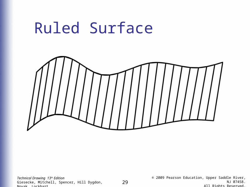
Ruled Surface
• A ruled surface is one that may be generated by sweeping a straight line, called a generatrix, along a path which may be straight or curved
• Any position of the generatrix is an element of the surface
• A ruled surface may be a plane, single curved surface, or a warped surface
29Technical Drawing 13th EditionGiesecke, Mitchell, Spencer, Hill Dygdon, Novak, Lockhart
© 2009 Pearson Education, Upper Saddle River, NJ 07458.
All Rights Reserved.
Ruled Surface
30Technical Drawing 13th EditionGiesecke, Mitchell, Spencer, Hill Dygdon, Novak, Lockhart
© 2009 Pearson Education, Upper Saddle River, NJ 07458.
All Rights Reserved.
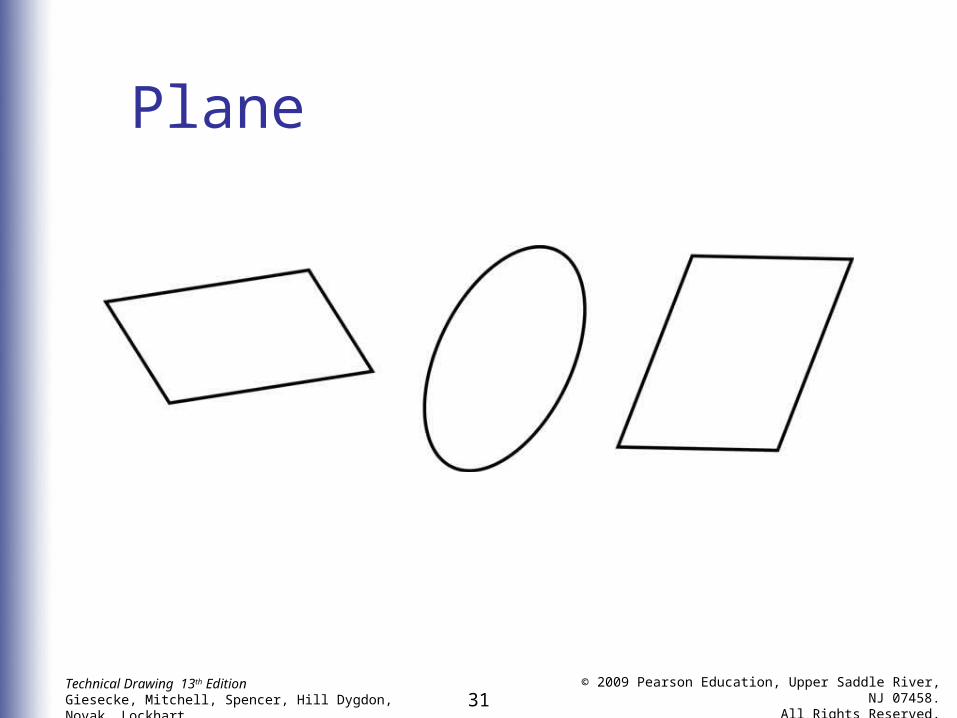
Plane
• A plane is a ruled surface that is generated by a line, one point of which moves along a straight path while the generatrix remains parallel to its original position
31Technical Drawing 13th EditionGiesecke, Mitchell, Spencer, Hill Dygdon, Novak, Lockhart
© 2009 Pearson Education, Upper Saddle River, NJ 07458.
All Rights Reserved.
Plane
32Technical Drawing 13th EditionGiesecke, Mitchell, Spencer, Hill Dygdon, Novak, Lockhart
© 2009 Pearson Education, Upper Saddle River, NJ 07458.
All Rights Reserved.
Single-curved Surface
• A single-curved surface is a developable ruled surface that can be unrolled to coincide with a plane
• Any two adjacent positions of the generatrix lie in the same plane• Examples are the cylinder and the
cone
33Technical Drawing 13th EditionGiesecke, Mitchell, Spencer, Hill Dygdon, Novak, Lockhart
© 2009 Pearson Education, Upper Saddle River, NJ 07458.
All Rights Reserved.
Double-curved Surface
• A double-curved surface is generated by a curved line and has no straight-line elements
• A surface generated by revolving a curved line about a straight line in the plane of the curve is called a double-curved surface of revolution• Examples are the sphere, torus,
ellipsoid, and hyperboloid
34Technical Drawing 13th EditionGiesecke, Mitchell, Spencer, Hill Dygdon, Novak, Lockhart
© 2009 Pearson Education, Upper Saddle River, NJ 07458.
All Rights Reserved.
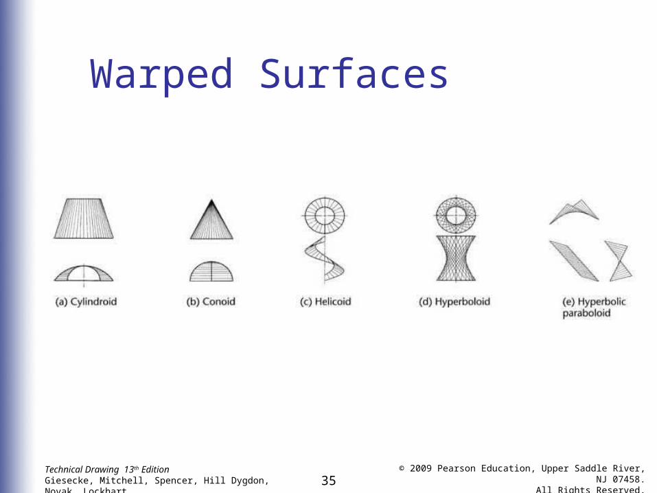
Warped Surface
• A warped surface is a ruled surface that is not developable
• No two adjacent positions of the generatrix lie in a flat plane
• Warped surfaces cannot be unrolled or unfolded to lie flat
35Technical Drawing 13th EditionGiesecke, Mitchell, Spencer, Hill Dygdon, Novak, Lockhart
© 2009 Pearson Education, Upper Saddle River, NJ 07458.
All Rights Reserved.
Warped Surfaces
36Technical Drawing 13th EditionGiesecke, Mitchell, Spencer, Hill Dygdon, Novak, Lockhart
© 2009 Pearson Education, Upper Saddle River, NJ 07458.
All Rights Reserved.
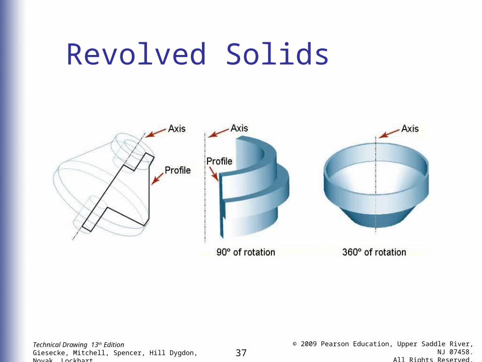
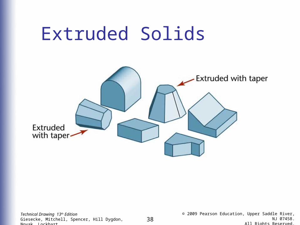
Revolved and Extruded Solids• A revolved solid is created by
revolving a plane figure about an axis
• An extruded solid is formed by sweeping a shape along a linear path
• Solids bounded by warped surfaces have no group name
37Technical Drawing 13th EditionGiesecke, Mitchell, Spencer, Hill Dygdon, Novak, Lockhart
© 2009 Pearson Education, Upper Saddle River, NJ 07458.
All Rights Reserved.
Revolved Solids
38Technical Drawing 13th EditionGiesecke, Mitchell, Spencer, Hill Dygdon, Novak, Lockhart
© 2009 Pearson Education, Upper Saddle River, NJ 07458.
All Rights Reserved.
Extruded Solids
39Technical Drawing 13th EditionGiesecke, Mitchell, Spencer, Hill Dygdon, Novak, Lockhart
© 2009 Pearson Education, Upper Saddle River, NJ 07458.
All Rights Reserved.
Principles of Intersections
• Typical examples of the need for accurate drawings showing the intersections of planes and solids include:• Openings in roof surfaces for flues
and stacks• Openings in wall surfaces for pipes,
chutes, etc.• The building of sheet-metal structures
40Technical Drawing 13th EditionGiesecke, Mitchell, Spencer, Hill Dygdon, Novak, Lockhart
© 2009 Pearson Education, Upper Saddle River, NJ 07458.
All Rights Reserved.
Principles of Intersections
• For solids bounded by plane surfaces, you need only find the points of intersection of the edges of the solid with the plane and join these points in consecutive order with straight lines
41Technical Drawing 13th EditionGiesecke, Mitchell, Spencer, Hill Dygdon, Novak, Lockhart
© 2009 Pearson Education, Upper Saddle River, NJ 07458.
All Rights Reserved.
Principles of Intersections
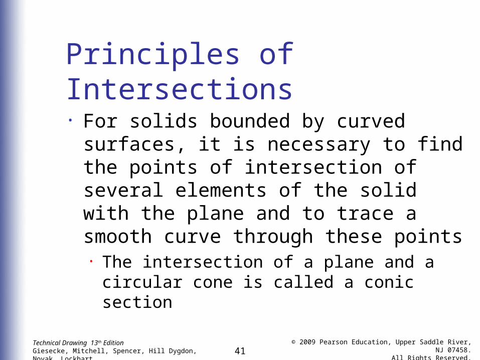
• For solids bounded by curved surfaces, it is necessary to find the points of intersection of several elements of the solid with the plane and to trace a smooth curve through these points• The intersection of a plane and a
circular cone is called a conic section
42Technical Drawing 13th EditionGiesecke, Mitchell, Spencer, Hill Dygdon, Novak, Lockhart
© 2009 Pearson Education, Upper Saddle River, NJ 07458.
All Rights Reserved.
Developments
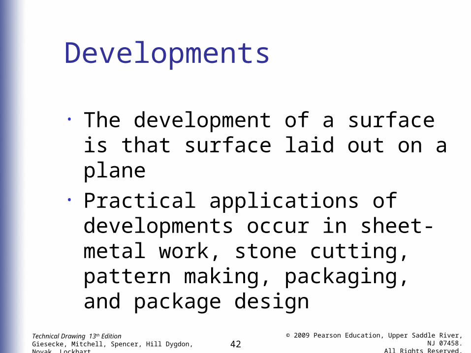
• The development of a surface is that surface laid out on a plane
• Practical applications of developments occur in sheet-metal work, stone cutting, pattern making, packaging, and package design
43Technical Drawing 13th EditionGiesecke, Mitchell, Spencer, Hill Dygdon, Novak, Lockhart
© 2009 Pearson Education, Upper Saddle River, NJ 07458.
All Rights Reserved.
Triangulation
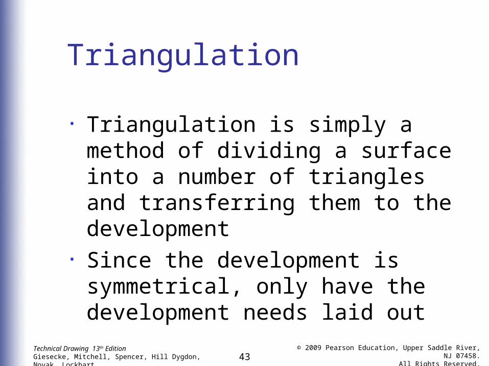
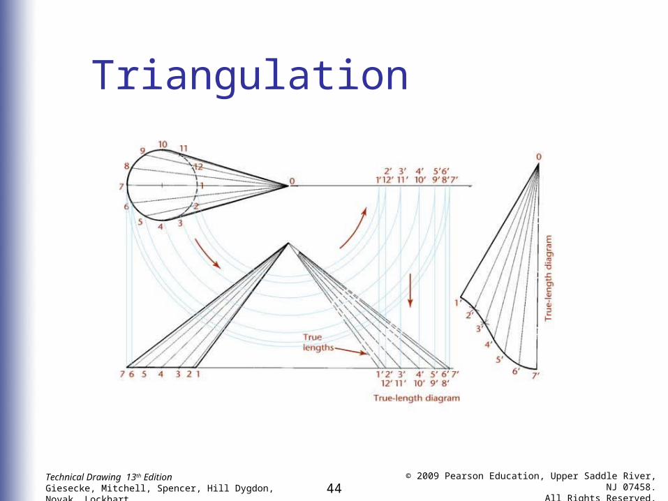
• Triangulation is simply a method of dividing a surface into a number of triangles and transferring them to the development
• Since the development is symmetrical, only have the development needs laid out
44Technical Drawing 13th EditionGiesecke, Mitchell, Spencer, Hill Dygdon, Novak, Lockhart
© 2009 Pearson Education, Upper Saddle River, NJ 07458.
All Rights Reserved.
Triangulation
45Technical Drawing 13th EditionGiesecke, Mitchell, Spencer, Hill Dygdon, Novak, Lockhart
© 2009 Pearson Education, Upper Saddle River, NJ 07458.
All Rights Reserved.
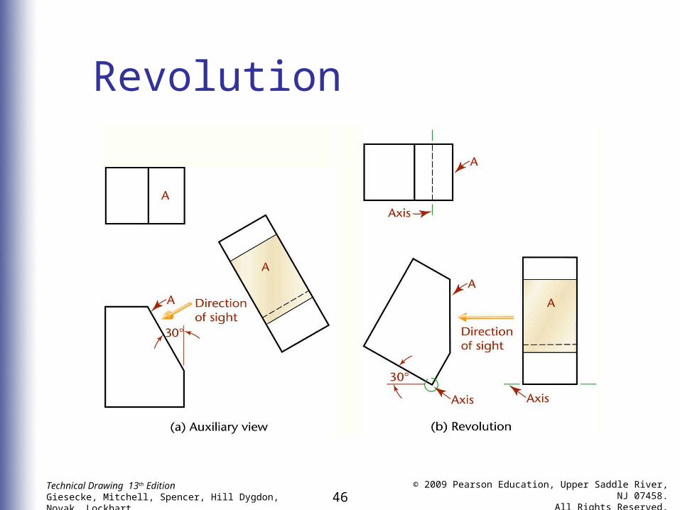
Revolution
• Revolution, like auxiliary-view projection, is a method of determining the true length and true size of inclined and oblique lines and planes
46Technical Drawing 13th EditionGiesecke, Mitchell, Spencer, Hill Dygdon, Novak, Lockhart
© 2009 Pearson Education, Upper Saddle River, NJ 07458.
All Rights Reserved.
Revolution