Embed Size (px)
Citation preview
C H A P T E R T E N
DIMENSIONINGDIMENSIONING
2Technical Drawing with Engineering Graphics, 14/eGiesecke, Hill, Spencer, Dygdon, Novak, Lockhart, Goodman
© 2012, 2009, 2003, Pearson Higher Education,Upper Saddle River, NJ 07458. • All Rights Reserved.
OBJECTIVESOBJECTIVES
1. Use conventional dimensioning techniques to describe size and shape accurately on an engineering drawing.
2. Create and read a drawing at a specified scale.
3. Correctly place dimension lines, extension lines, angles, and notes.
4. Dimension circles, arcs, and inclined surfaces.
5. Apply finish symbols and notes to a drawing.
6. Dimension contours.
7. Use standard practices for dimensioning prisms, cylinders, holes, and curves.
8. List practices for dimensioning a solid model as documentation.
9. Identify guidelines for the dos and don’ts of dimensioning.
3Technical Drawing with Engineering Graphics, 14/eGiesecke, Hill, Spencer, Dygdon, Novak, Lockhart, Goodman
© 2012, 2009, 2003, Pearson Higher Education,Upper Saddle River, NJ 07458. • All Rights Reserved.
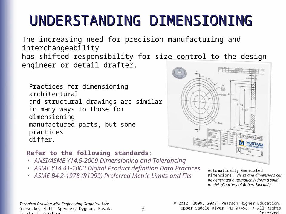
UNDERSTANDING DIMENSIONINGUNDERSTANDING DIMENSIONINGThe increasing need for precision manufacturing and interchangeabilityhas shifted responsibility for size control to the design engineer or detail drafter.
Practices for dimensioning architecturaland structural drawings are similarin many ways to those for dimensioningmanufactured parts, but some practicesdiffer.
Refer to the following standards:• ANSI/ASME Y14.5-2009 Dimensioning and Tolerancing• ASME Y14.41-2003 Digital Product definition Data Practices• ASME B4.2-1978 (R1999) Preferred Metric Limits and Fits
Automatically Generated Dimensions. Views and dimensions can be generated automatically from a solid model. (Courtesy of Robert Kincaid.)
4Technical Drawing with Engineering Graphics, 14/eGiesecke, Hill, Spencer, Dygdon, Novak, Lockhart, Goodman
© 2012, 2009, 2003, Pearson Higher Education,Upper Saddle River, NJ 07458. • All Rights Reserved.
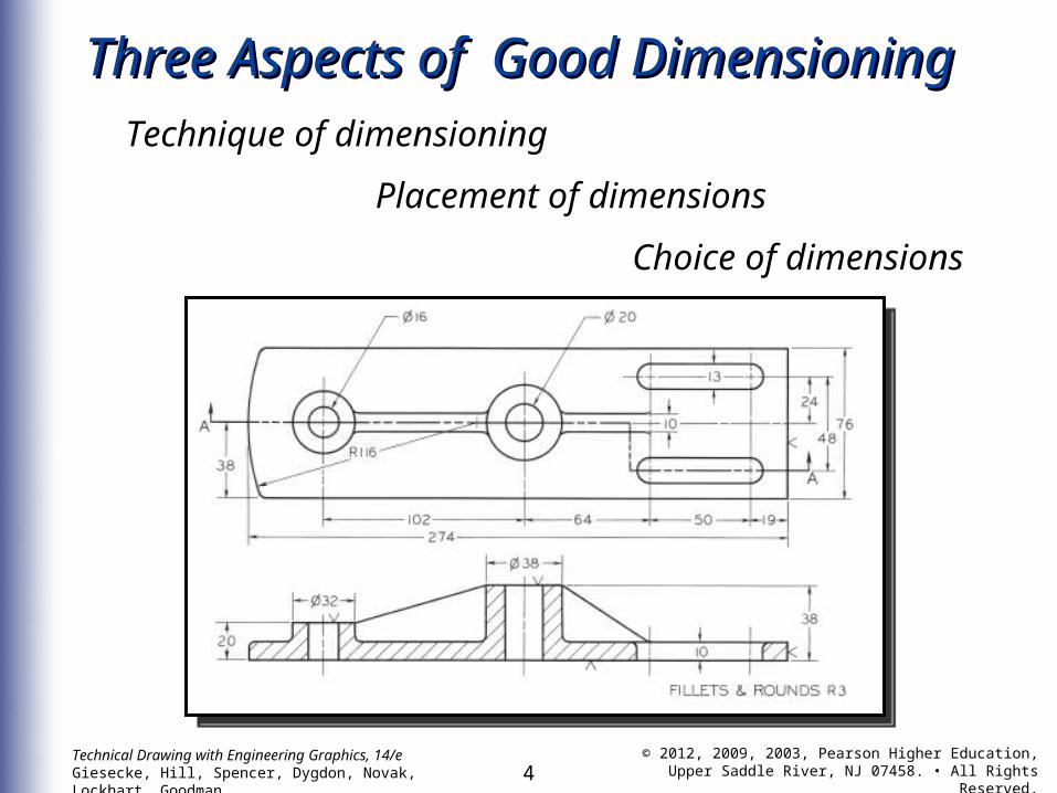
Three Aspects of Good DimensioningThree Aspects of Good DimensioningTechnique of dimensioning
Placement of dimensions
Choice of dimensions
5Technical Drawing with Engineering Graphics, 14/eGiesecke, Hill, Spencer, Dygdon, Novak, Lockhart, Goodman
© 2012, 2009, 2003, Pearson Higher Education,Upper Saddle River, NJ 07458. • All Rights Reserved.
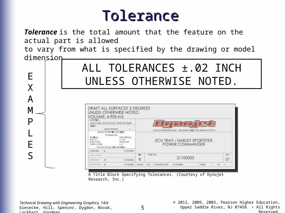
ToleranceToleranceTolerance is the total amount that the feature on the actual part is allowedto vary from what is specified by the drawing or model dimension.
A Title Block Specifying Tolerances. (Courtesy of Dynojet Research, Inc.)
ALL TOLERANCES ±.02 INCHUNLESS OTHERWISE NOTED.E
XAMPLES
6Technical Drawing with Engineering Graphics, 14/eGiesecke, Hill, Spencer, Dygdon, Novak, Lockhart, Goodman
© 2012, 2009, 2003, Pearson Higher Education,Upper Saddle River, NJ 07458. • All Rights Reserved.
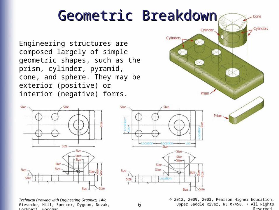
Geometric BreakdownGeometric Breakdown
Engineering structures are composed largely of simple geometric shapes, such as the prism, cylinder, pyramid, cone, and sphere. They may be exterior (positive) or interior (negative) forms.
7Technical Drawing with Engineering Graphics, 14/eGiesecke, Hill, Spencer, Dygdon, Novak, Lockhart, Goodman
© 2012, 2009, 2003, Pearson Higher Education,Upper Saddle River, NJ 07458. • All Rights Reserved.
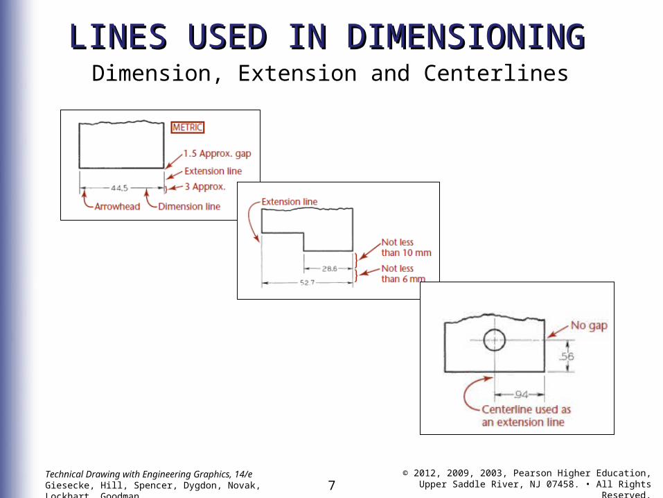
LINES USED IN DIMENSIONINGLINES USED IN DIMENSIONINGDimension, Extension and Centerlines
8Technical Drawing with Engineering Graphics, 14/eGiesecke, Hill, Spencer, Dygdon, Novak, Lockhart, Goodman
© 2012, 2009, 2003, Pearson Higher Education,Upper Saddle River, NJ 07458. • All Rights Reserved.
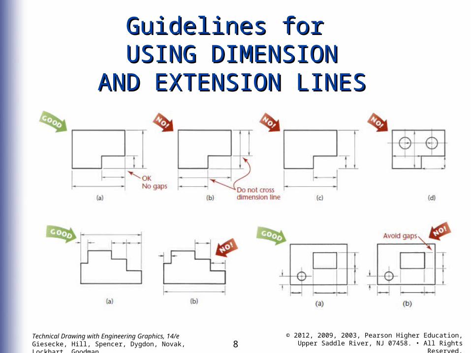
Guidelines for Guidelines for USING DIMENSIONUSING DIMENSION
AND EXTENSION LINESAND EXTENSION LINES
9Technical Drawing with Engineering Graphics, 14/eGiesecke, Hill, Spencer, Dygdon, Novak, Lockhart, Goodman
© 2012, 2009, 2003, Pearson Higher Education,Upper Saddle River, NJ 07458. • All Rights Reserved.
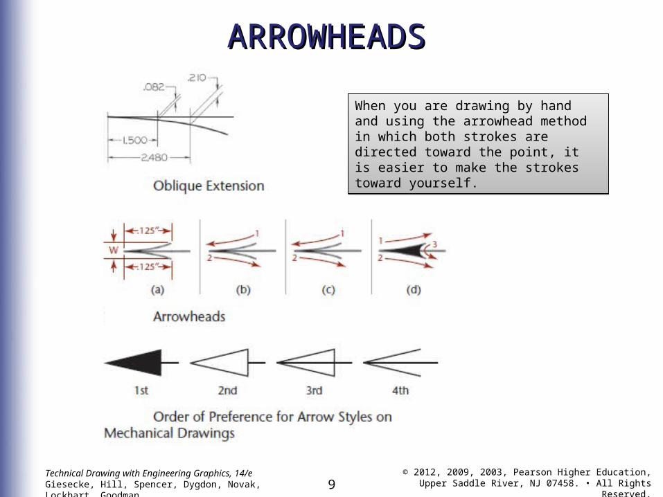
ARROWHEADSARROWHEADS
When you are drawing by hand and using the arrowhead method in which both strokes are directed toward the point, it is easier to make the strokes toward yourself.
When you are drawing by hand and using the arrowhead method in which both strokes are directed toward the point, it is easier to make the strokes toward yourself.
10Technical Drawing with Engineering Graphics, 14/eGiesecke, Hill, Spencer, Dygdon, Novak, Lockhart, Goodman
© 2012, 2009, 2003, Pearson Higher Education,Upper Saddle River, NJ 07458. • All Rights Reserved.
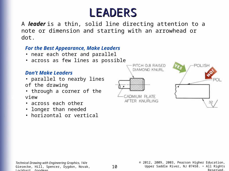
LEADERSLEADERSA leader is a thin, solid line directing attention to a note or dimension and starting with an arrowhead or dot.
For the Best Appearance, Make Leaders• near each other and parallel• across as few lines as possibleDon’t Make Leaders• parallel to nearby lines of the drawing• through a corner of the view• across each other• longer than needed• horizontal or vertical
11Technical Drawing with Engineering Graphics, 14/eGiesecke, Hill, Spencer, Dygdon, Novak, Lockhart, Goodman
© 2012, 2009, 2003, Pearson Higher Education,Upper Saddle River, NJ 07458. • All Rights Reserved.
DRAWING SCALEDRAWING SCALEAND DIMENSIONINGAND DIMENSIONING
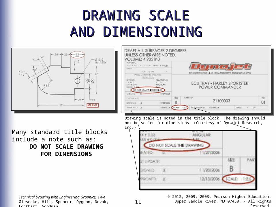
Many standard title blocks include a note such as:
DO NOT SCALE DRAWING FOR DIMENSIONS
Drawing scale is noted in the title block. The drawing should not be scaled for dimensions. (Courtesy of Dynojet Research, Inc.)
12Technical Drawing with Engineering Graphics, 14/eGiesecke, Hill, Spencer, Dygdon, Novak, Lockhart, Goodman
© 2012, 2009, 2003, Pearson Higher Education,Upper Saddle River, NJ 07458. • All Rights Reserved.
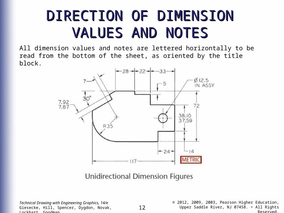
DIRECTION OF DIMENSIONDIRECTION OF DIMENSIONVALUES AND NOTESVALUES AND NOTES
All dimension values and notes are lettered horizontally to be read from the bottom of the sheet, as oriented by the title block.
13Technical Drawing with Engineering Graphics, 14/eGiesecke, Hill, Spencer, Dygdon, Novak, Lockhart, Goodman
© 2012, 2009, 2003, Pearson Higher Education,Upper Saddle River, NJ 07458. • All Rights Reserved.
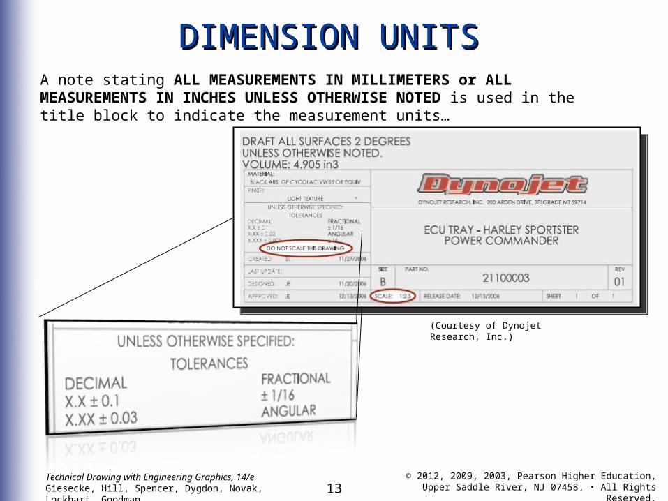
DIMENSION UNITSDIMENSION UNITSA note stating ALL MEASUREMENTS IN MILLIMETERS or ALL MEASUREMENTS IN INCHES UNLESS OTHERWISE NOTED is used in the title block to indicate the measurement units…
(Courtesy of Dynojet Research, Inc.)
14Technical Drawing with Engineering Graphics, 14/eGiesecke, Hill, Spencer, Dygdon, Novak, Lockhart, Goodman
© 2012, 2009, 2003, Pearson Higher Education,Upper Saddle River, NJ 07458. • All Rights Reserved.
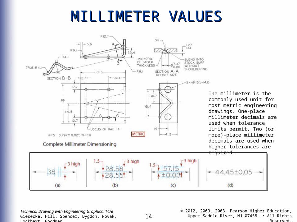
MILLIMETER VALUESMILLIMETER VALUES
The millimeter is the commonly used unit for most metric engineering drawings. One-place millimeter decimals are used when tolerance limits permit. Two (or more)–place millimeter decimals are used when higher tolerances are required.
15Technical Drawing with Engineering Graphics, 14/eGiesecke, Hill, Spencer, Dygdon, Novak, Lockhart, Goodman
© 2012, 2009, 2003, Pearson Higher Education,Upper Saddle River, NJ 07458. • All Rights Reserved.
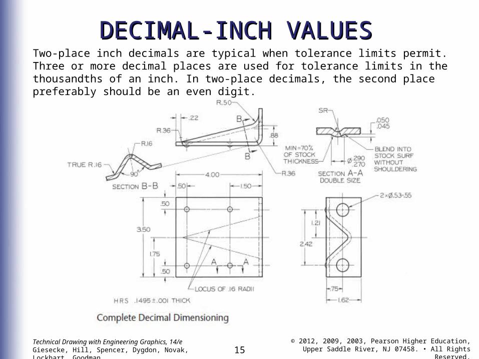
DECIMAL-INCH VALUESDECIMAL-INCH VALUESTwo-place inch decimals are typical when tolerance limits permit. Three or more decimal places are used for tolerance limits in the thousandths of an inch. In two-place decimals, the second place preferably should be an even digit.
16Technical Drawing with Engineering Graphics, 14/eGiesecke, Hill, Spencer, Dygdon, Novak, Lockhart, Goodman
© 2012, 2009, 2003, Pearson Higher Education,Upper Saddle River, NJ 07458. • All Rights Reserved.
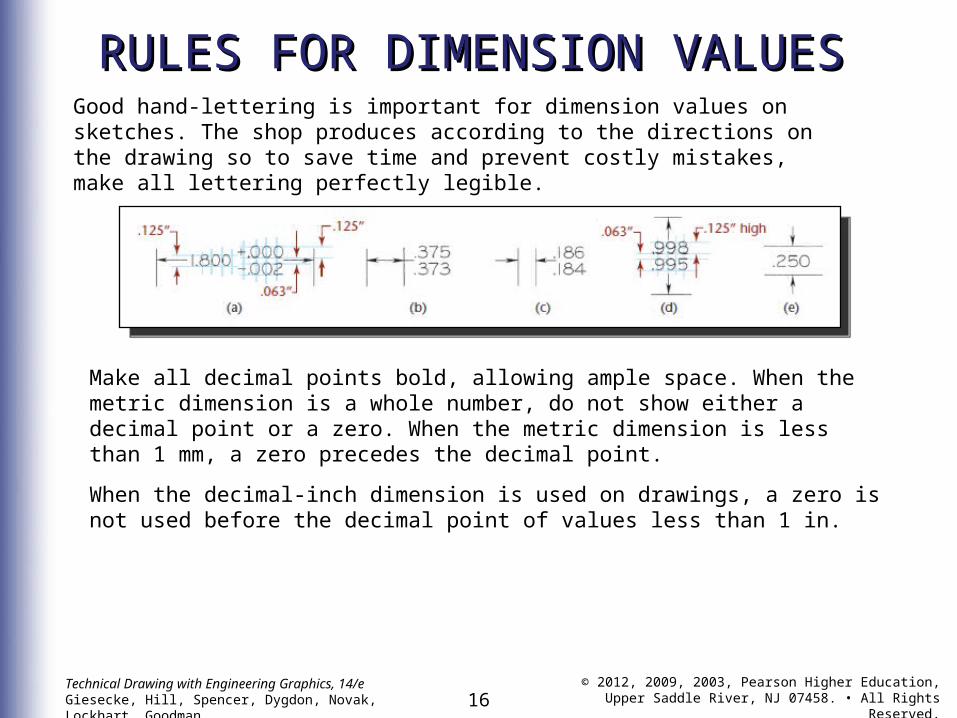
RULES FOR DIMENSION VALUESRULES FOR DIMENSION VALUESGood hand-lettering is important for dimension values on sketches. The shop produces according to the directions on the drawing so to save time and prevent costly mistakes, make all lettering perfectly legible.
Make all decimal points bold, allowing ample space. When the metric dimension is a whole number, do not show either a decimal point or a zero. When the metric dimension is less than 1 mm, a zero precedes the decimal point.
When the decimal-inch dimension is used on drawings, a zero is not used before the decimal point of values less than 1 in.
17Technical Drawing with Engineering Graphics, 14/eGiesecke, Hill, Spencer, Dygdon, Novak, Lockhart, Goodman
© 2012, 2009, 2003, Pearson Higher Education,Upper Saddle River, NJ 07458. • All Rights Reserved.
DUAL DIMENSIONING and DUAL DIMENSIONING and COMBINATION UNITSCOMBINATION UNITS
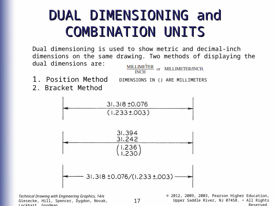
Dual dimensioning is used to show metric and decimal-inch dimensions on the same drawing. Two methods of displaying the dual dimensions are:
1. Position Method2. Bracket Method DIMENSIONS IN () ARE MILLIMETERS
18Technical Drawing with Engineering Graphics, 14/eGiesecke, Hill, Spencer, Dygdon, Novak, Lockhart, Goodman
© 2012, 2009, 2003, Pearson Higher Education,Upper Saddle River, NJ 07458. • All Rights Reserved.
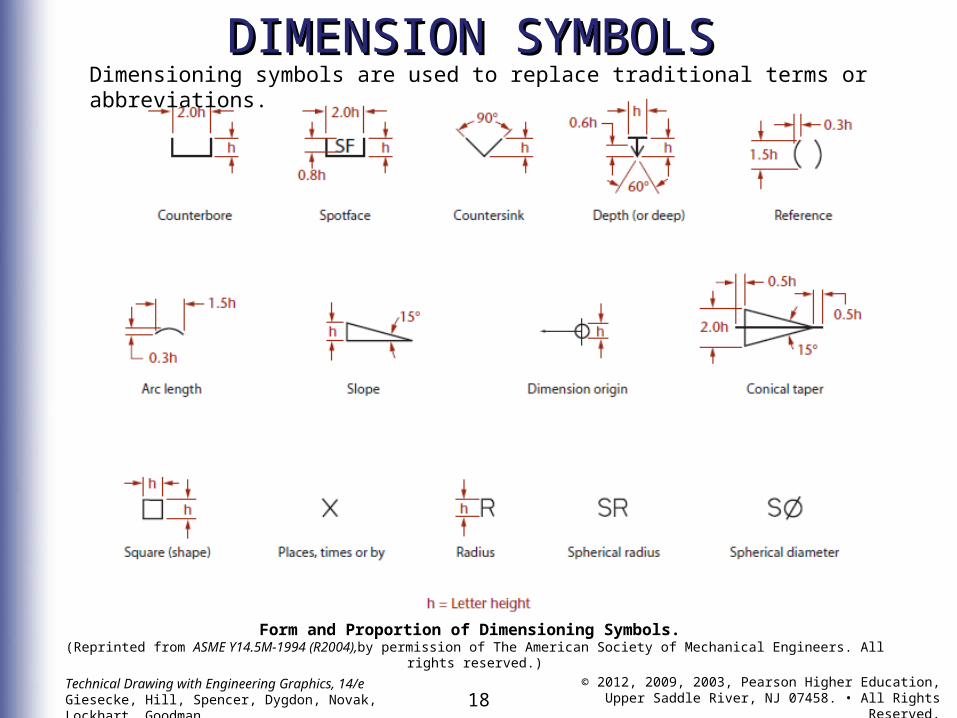
DIMENSION SYMBOLSDIMENSION SYMBOLSDimensioning symbols are used to replace traditional terms or abbreviations.
Form and Proportion of Dimensioning Symbols. (Reprinted from ASME Y14.5M-1994 (R2004),by permission of The American Society of Mechanical Engineers. All rights
reserved.)
19Technical Drawing with Engineering Graphics, 14/eGiesecke, Hill, Spencer, Dygdon, Novak, Lockhart, Goodman
© 2012, 2009, 2003, Pearson Higher Education,Upper Saddle River, NJ 07458. • All Rights Reserved.
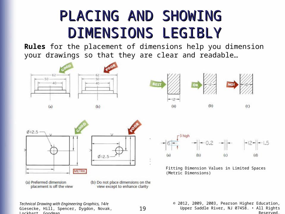
PLACING AND SHOWINGPLACING AND SHOWING DIMENSIONS LEGIBLY DIMENSIONS LEGIBLY
Rules for the placement of dimensions help you dimension your drawings so that they are clear and readable…
Fitting Dimension Values in Limited Spaces (Metric Dimensions)
20Technical Drawing with Engineering Graphics, 14/eGiesecke, Hill, Spencer, Dygdon, Novak, Lockhart, Goodman
© 2012, 2009, 2003, Pearson Higher Education,Upper Saddle River, NJ 07458. • All Rights Reserved.
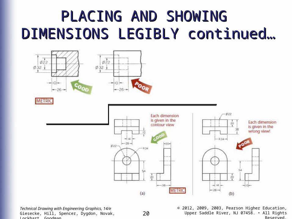
PLACING AND SHOWINGPLACING AND SHOWING DIMENSIONS LEGIBLY continued… DIMENSIONS LEGIBLY continued…
21Technical Drawing with Engineering Graphics, 14/eGiesecke, Hill, Spencer, Dygdon, Novak, Lockhart, Goodman
© 2012, 2009, 2003, Pearson Higher Education,Upper Saddle River, NJ 07458. • All Rights Reserved.
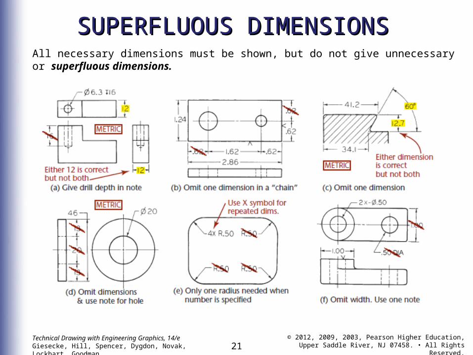
SUPERFLUOUS DIMENSIONSSUPERFLUOUS DIMENSIONSAll necessary dimensions must be shown, but do not give unnecessary or superfluous dimensions.
22Technical Drawing with Engineering Graphics, 14/eGiesecke, Hill, Spencer, Dygdon, Novak, Lockhart, Goodman
© 2012, 2009, 2003, Pearson Higher Education,Upper Saddle River, NJ 07458. • All Rights Reserved.
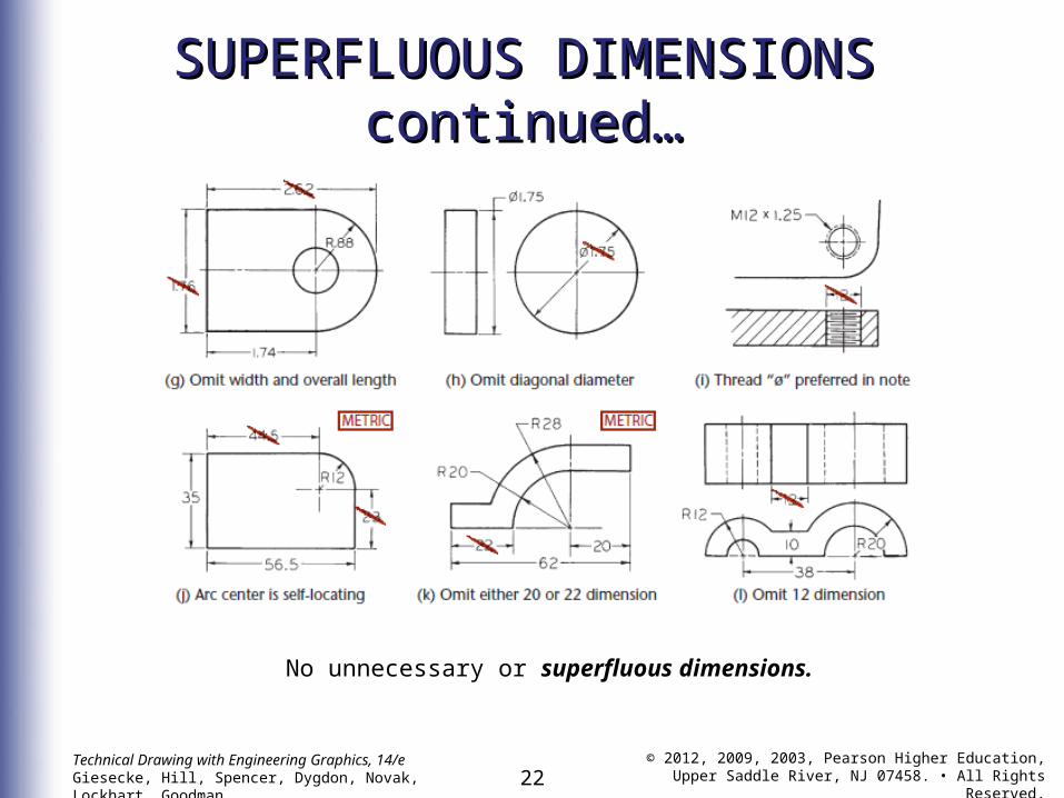
SUPERFLUOUS DIMENSIONS SUPERFLUOUS DIMENSIONS continued…continued…
No unnecessary or superfluous dimensions.
23Technical Drawing with Engineering Graphics, 14/eGiesecke, Hill, Spencer, Dygdon, Novak, Lockhart, Goodman
© 2012, 2009, 2003, Pearson Higher Education,Upper Saddle River, NJ 07458. • All Rights Reserved.
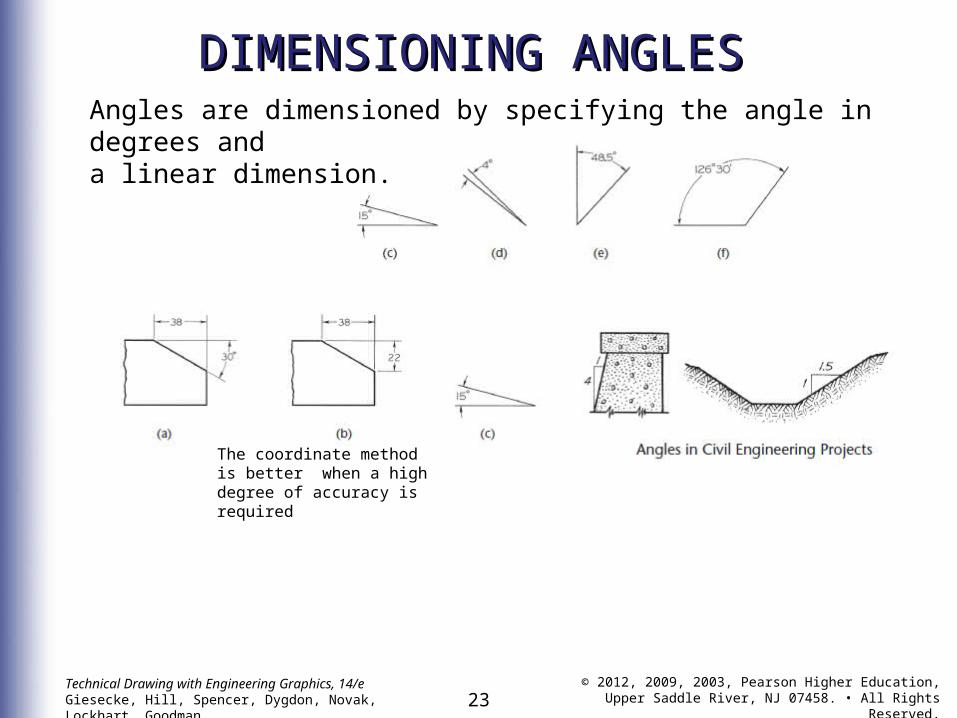
DIMENSIONING ANGLESDIMENSIONING ANGLESAngles are dimensioned by specifying the angle in degrees anda linear dimension.
The coordinate method is better when a high degree of accuracy is required
24Technical Drawing with Engineering Graphics, 14/eGiesecke, Hill, Spencer, Dygdon, Novak, Lockhart, Goodman
© 2012, 2009, 2003, Pearson Higher Education,Upper Saddle River, NJ 07458. • All Rights Reserved.
DIMENSIONING ARCS, DIMENSIONING ARCS, FILLETS AND FILLETS AND ROUNDSROUNDS
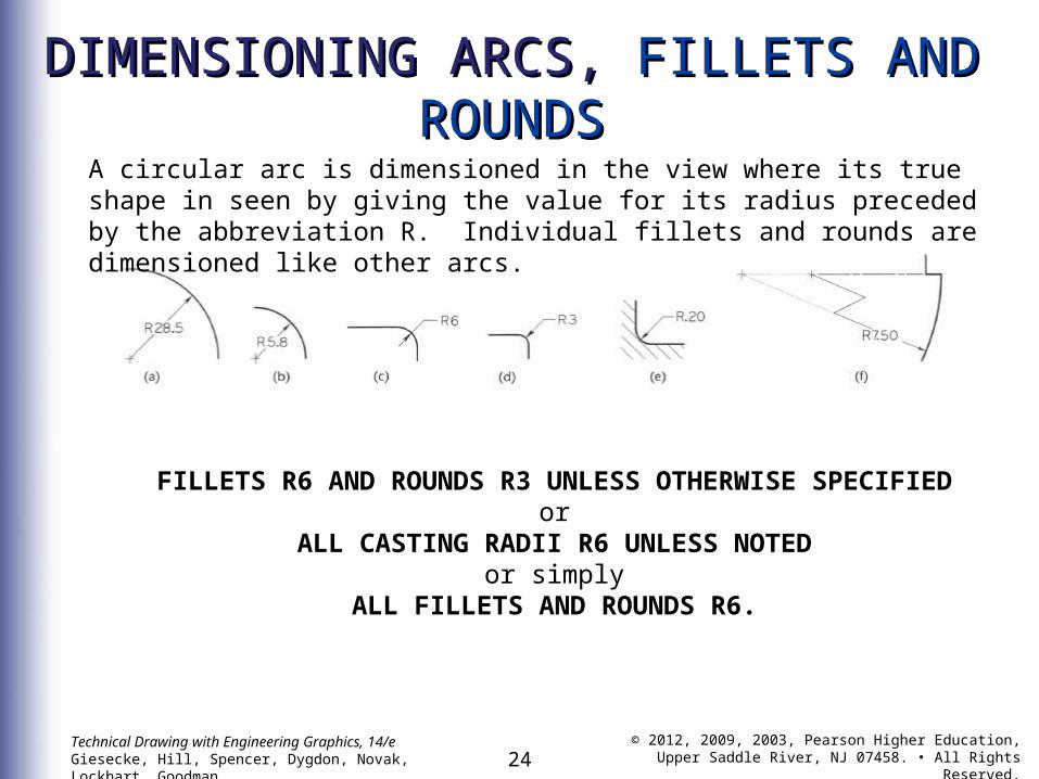
A circular arc is dimensioned in the view where its true shape in seen by giving the value for its radius preceded by the abbreviation R. Individual fillets and rounds are dimensioned like other arcs.
FILLETS R6 AND ROUNDS R3 UNLESS OTHERWISE SPECIFIED
orALL CASTING RADII R6 UNLESS NOTED
or simplyALL FILLETS AND ROUNDS R6.
25Technical Drawing with Engineering Graphics, 14/eGiesecke, Hill, Spencer, Dygdon, Novak, Lockhart, Goodman
© 2012, 2009, 2003, Pearson Higher Education,Upper Saddle River, NJ 07458. • All Rights Reserved.
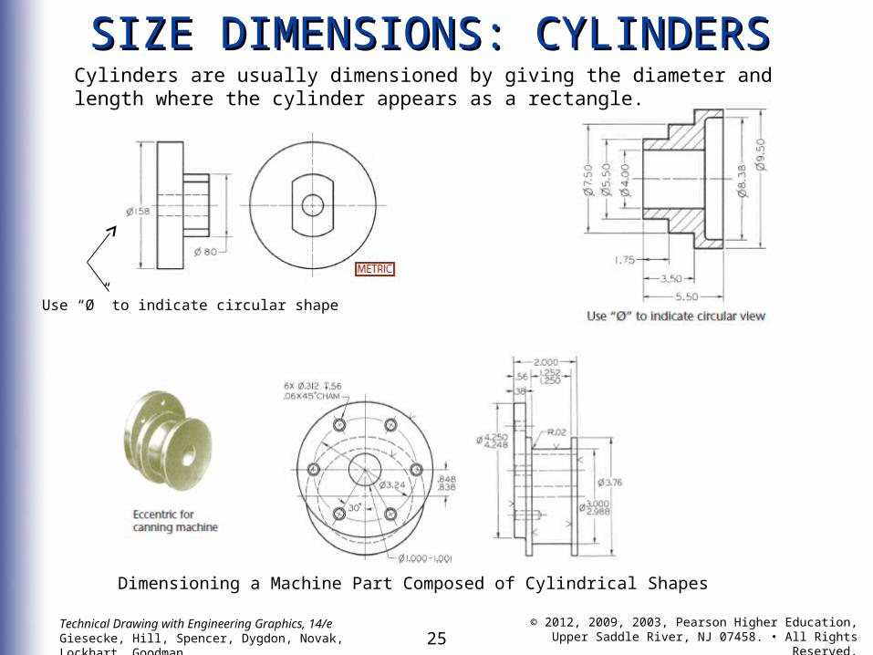
SIZE DIMENSIONS: CYLINDERSSIZE DIMENSIONS: CYLINDERS
Use “Ø” to indicate circular shape
Dimensioning a Machine Part Composed of Cylindrical Shapes
Cylinders are usually dimensioned by giving the diameter and length where the cylinder appears as a rectangle.
26Technical Drawing with Engineering Graphics, 14/eGiesecke, Hill, Spencer, Dygdon, Novak, Lockhart, Goodman
© 2012, 2009, 2003, Pearson Higher Education,Upper Saddle River, NJ 07458. • All Rights Reserved.
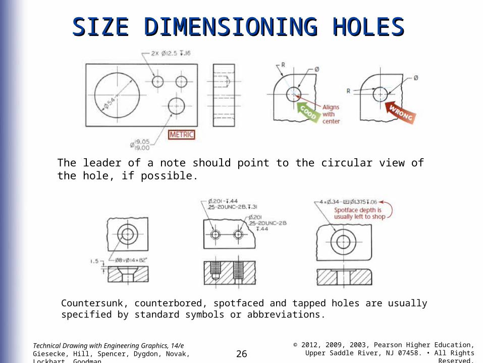
SIZE DIMENSIONING HOLESSIZE DIMENSIONING HOLES
Countersunk, counterbored, spotfaced and tapped holes are usually specified by standard symbols or abbreviations.
The leader of a note should point to the circular view of the hole, if possible.
27Technical Drawing with Engineering Graphics, 14/eGiesecke, Hill, Spencer, Dygdon, Novak, Lockhart, Goodman
© 2012, 2009, 2003, Pearson Higher Education,Upper Saddle River, NJ 07458. • All Rights Reserved.
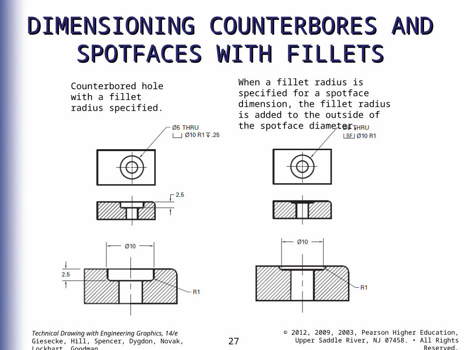
DIMENSIONING COUNTERBORES AND DIMENSIONING COUNTERBORES AND SPOTFACES WITH FILLETSSPOTFACES WITH FILLETS
Counterbored hole with a fillet radius specified.
When a fillet radius is specified for a spotface dimension, the fillet radius is added to the outside of the spotface diameter,
28Technical Drawing with Engineering Graphics, 14/eGiesecke, Hill, Spencer, Dygdon, Novak, Lockhart, Goodman
© 2012, 2009, 2003, Pearson Higher Education,Upper Saddle River, NJ 07458. • All Rights Reserved.
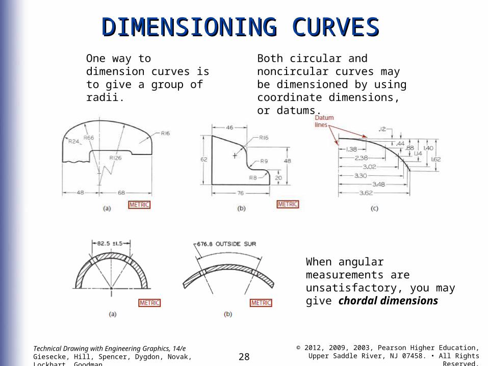
DIMENSIONING CURVESDIMENSIONING CURVESOne way to dimension curves is to give a group of radii.
Both circular and noncircular curves may be dimensioned by using coordinate dimensions,or datums.
When angular measurements are unsatisfactory, you may give chordal dimensions
29Technical Drawing with Engineering Graphics, 14/eGiesecke, Hill, Spencer, Dygdon, Novak, Lockhart, Goodman
© 2012, 2009, 2003, Pearson Higher Education,Upper Saddle River, NJ 07458. • All Rights Reserved.
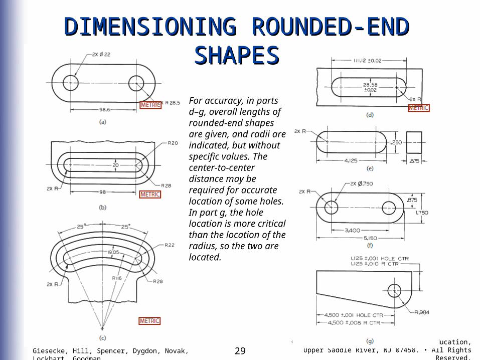
DIMENSIONING ROUNDED-END DIMENSIONING ROUNDED-END SHAPESSHAPES
For accuracy, in parts d–g, overall lengths of rounded-end shapes are given, and radii are indicated, but without specific values. The center-to-center distance may be required for accurate location of some holes. In part g, the hole location is more critical than the location of the radius, so the two are located.
30Technical Drawing with Engineering Graphics, 14/eGiesecke, Hill, Spencer, Dygdon, Novak, Lockhart, Goodman
© 2012, 2009, 2003, Pearson Higher Education,Upper Saddle River, NJ 07458. • All Rights Reserved.
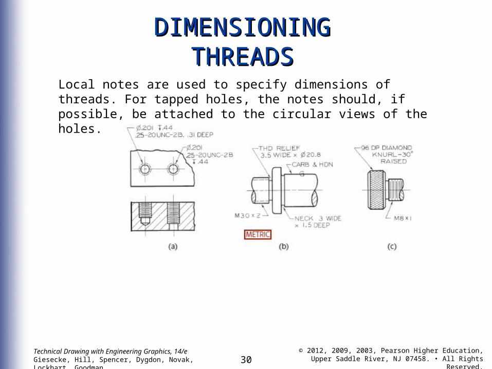
DIMENSIONINGDIMENSIONINGTHREADSTHREADS
Local notes are used to specify dimensions of threads. For tapped holes, the notes should, if possible, be attached to the circular views of the holes.
31Technical Drawing with Engineering Graphics, 14/eGiesecke, Hill, Spencer, Dygdon, Novak, Lockhart, Goodman
© 2012, 2009, 2003, Pearson Higher Education,Upper Saddle River, NJ 07458. • All Rights Reserved.
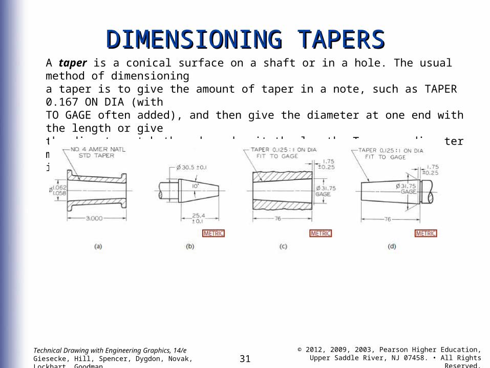
DIMENSIONING TAPERSDIMENSIONING TAPERSA taper is a conical surface on a shaft or in a hole. The usual method of dimensioninga taper is to give the amount of taper in a note, such as TAPER 0.167 ON DIA (withTO GAGE often added), and then give the diameter at one end with the length or givethe diameter at both ends and omit the length. Taper on diameter means the differencein diameter per unit of length.
32Technical Drawing with Engineering Graphics, 14/eGiesecke, Hill, Spencer, Dygdon, Novak, Lockhart, Goodman
© 2012, 2009, 2003, Pearson Higher Education,Upper Saddle River, NJ 07458. • All Rights Reserved.
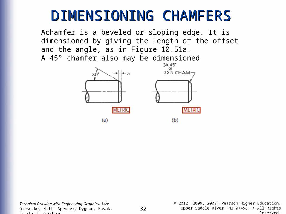
DIMENSIONING CHAMFERSDIMENSIONING CHAMFERSAchamfer is a beveled or sloping edge. It is dimensioned by giving the length of the offset and the angle, as in Figure 10.51a.A 45° chamfer also may be dimensioned
33Technical Drawing with Engineering Graphics, 14/eGiesecke, Hill, Spencer, Dygdon, Novak, Lockhart, Goodman
© 2012, 2009, 2003, Pearson Higher Education,Upper Saddle River, NJ 07458. • All Rights Reserved.
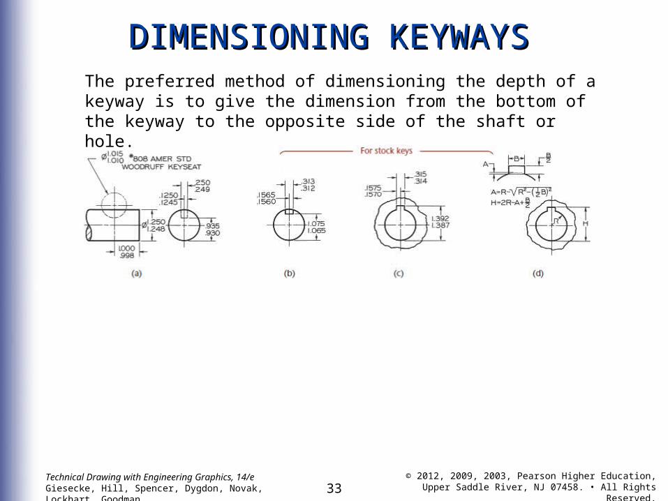
DIMENSIONING KEYWAYSDIMENSIONING KEYWAYSThe preferred method of dimensioning the depth of a keyway is to give the dimension from the bottom of the keyway to the opposite side of the shaft or hole.
34Technical Drawing with Engineering Graphics, 14/eGiesecke, Hill, Spencer, Dygdon, Novak, Lockhart, Goodman
© 2012, 2009, 2003, Pearson Higher Education,Upper Saddle River, NJ 07458. • All Rights Reserved.
DIMENSIONING KNURLSDIMENSIONING KNURLS
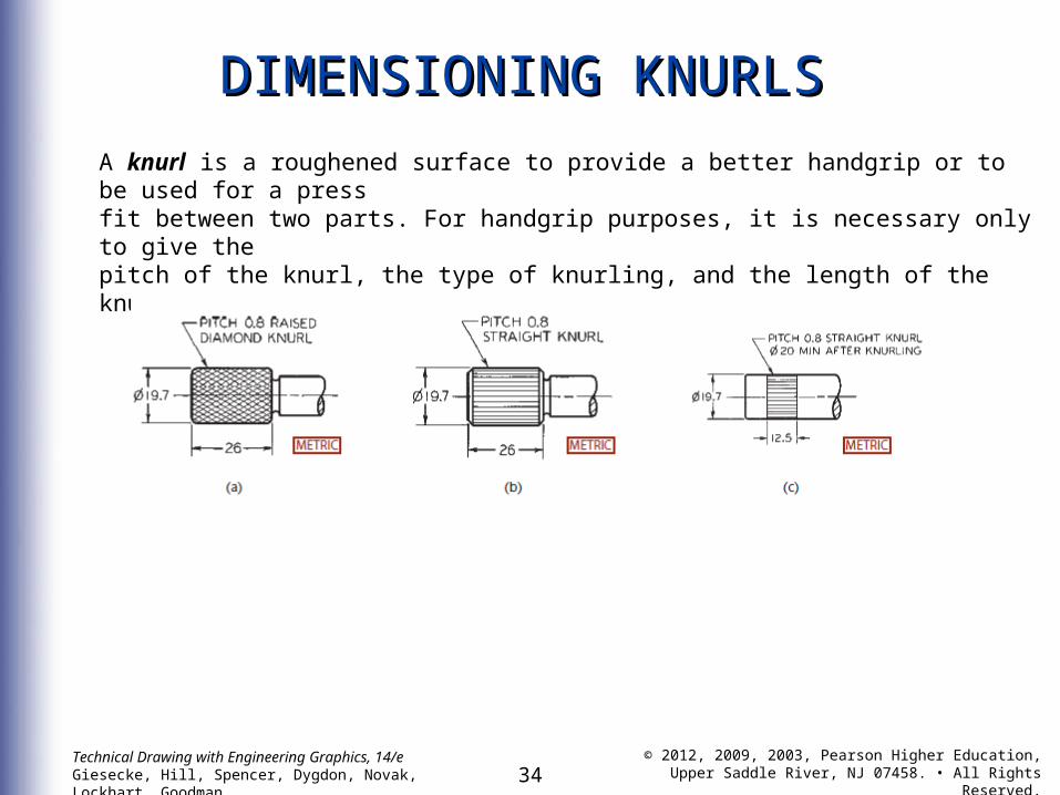
A knurl is a roughened surface to provide a better handgrip or to be used for a pressfit between two parts. For handgrip purposes, it is necessary only to give thepitch of the knurl, the type of knurling, and the length of the knurled area.
35Technical Drawing with Engineering Graphics, 14/eGiesecke, Hill, Spencer, Dygdon, Novak, Lockhart, Goodman
© 2012, 2009, 2003, Pearson Higher Education,Upper Saddle River, NJ 07458. • All Rights Reserved.
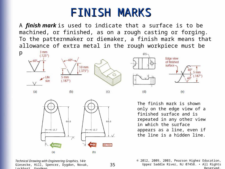
FINISH MARKSFINISH MARKSA finish mark is used to indicate that a surface is to be machined, or finished, as on a rough casting or forging. To the patternmaker or diemaker, a finish mark means that allowance of extra metal in the rough workpiece must be provided for the machining.
The finish mark is shown only on the edge view of a finished surface and is repeated in any other view in which the surface appears as a line, even if the line is a hidden line.

36Technical Drawing with Engineering Graphics, 14/eGiesecke, Hill, Spencer, Dygdon, Novak, Lockhart, Goodman
© 2012, 2009, 2003, Pearson Higher Education,Upper Saddle River, NJ 07458. • All Rights Reserved.
37Technical Drawing with Engineering Graphics, 14/eGiesecke, Hill, Spencer, Dygdon, Novak, Lockhart, Goodman
© 2012, 2009, 2003, Pearson Higher Education,Upper Saddle River, NJ 07458. • All Rights Reserved.
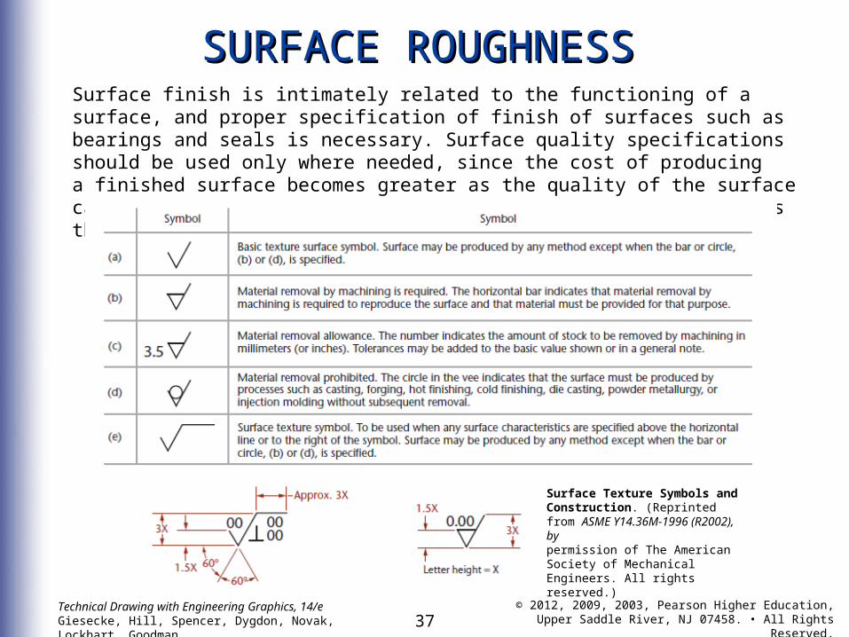
SURFACE ROUGHNESSSURFACE ROUGHNESSSurface finish is intimately related to the functioning of a surface, and proper specification of finish of surfaces such as bearings and seals is necessary. Surface quality specifications should be used only where needed, since the cost of producinga finished surface becomes greater as the quality of the surface called for is increased. Generally, the ideal surface finish is the roughest that will do the job satisfactorily.
Surface Texture Symbols and Construction. (Reprinted from ASME Y14.36M-1996 (R2002), bypermission of The American Society of Mechanical Engineers. All rights reserved.)
38Technical Drawing with Engineering Graphics, 14/eGiesecke, Hill, Spencer, Dygdon, Novak, Lockhart, Goodman
© 2012, 2009, 2003, Pearson Higher Education,Upper Saddle River, NJ 07458. • All Rights Reserved.
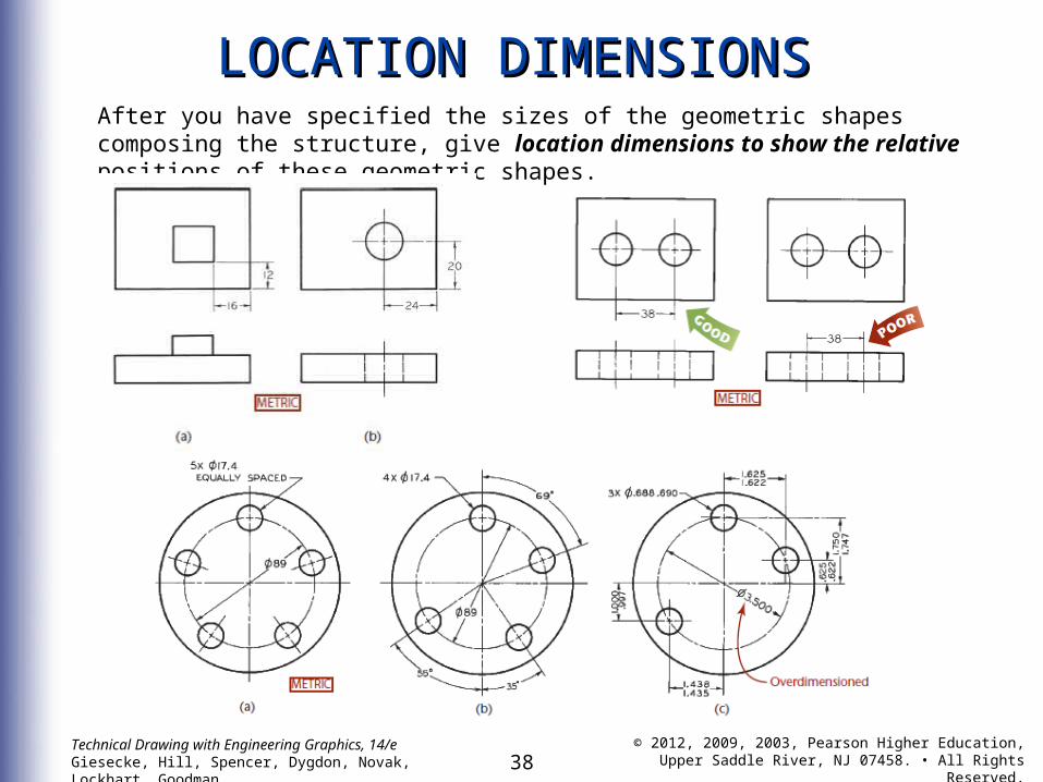
LOCATION DIMENSIONSLOCATION DIMENSIONSAfter you have specified the sizes of the geometric shapes composing the structure, give location dimensions to show the relative positions of these geometric shapes.
39Technical Drawing with Engineering Graphics, 14/eGiesecke, Hill, Spencer, Dygdon, Novak, Lockhart, Goodman
© 2012, 2009, 2003, Pearson Higher Education,Upper Saddle River, NJ 07458. • All Rights Reserved.
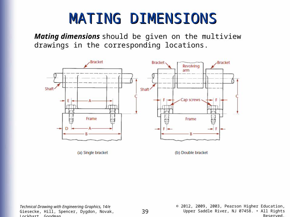
MATING DIMENSIONSMATING DIMENSIONSMating dimensions should be given on the multiview drawings in the corresponding locations.
40Technical Drawing with Engineering Graphics, 14/eGiesecke, Hill, Spencer, Dygdon, Novak, Lockhart, Goodman
© 2012, 2009, 2003, Pearson Higher Education,Upper Saddle River, NJ 07458. • All Rights Reserved.
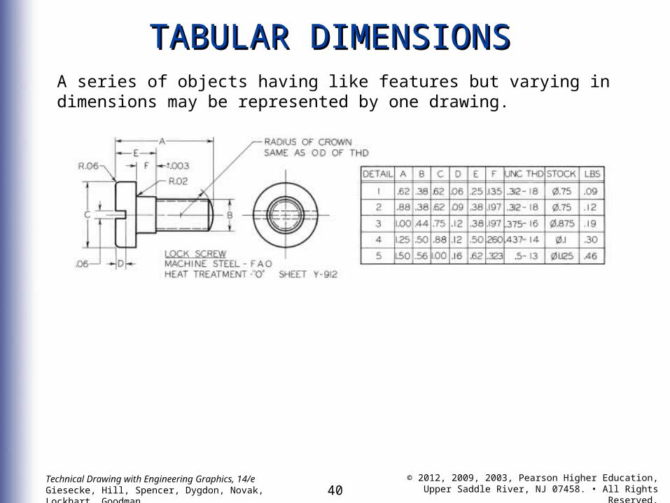
TABULAR DIMENSIONSTABULAR DIMENSIONSA series of objects having like features but varying in dimensions may be represented by one drawing.
41Technical Drawing with Engineering Graphics, 14/eGiesecke, Hill, Spencer, Dygdon, Novak, Lockhart, Goodman
© 2012, 2009, 2003, Pearson Higher Education,Upper Saddle River, NJ 07458. • All Rights Reserved.
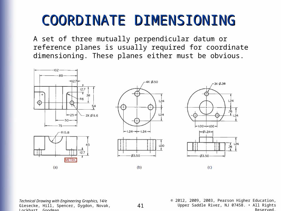
COORDINATE DIMENSIONINGCOORDINATE DIMENSIONINGA set of three mutually perpendicular datum or reference planes is usually required for coordinate dimensioning. These planes either must be obvious.
42Technical Drawing with Engineering Graphics, 14/eGiesecke, Hill, Spencer, Dygdon, Novak, Lockhart, Goodman
© 2012, 2009, 2003, Pearson Higher Education,Upper Saddle River, NJ 07458. • All Rights Reserved.
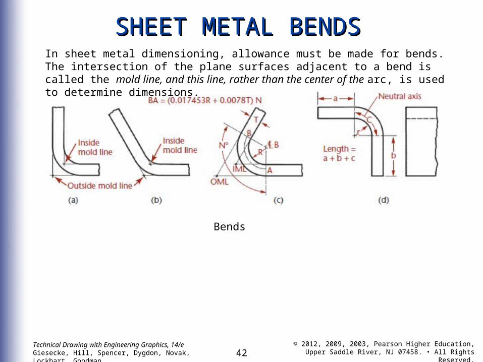
SHEET METAL BENDSSHEET METAL BENDS
Bends
In sheet metal dimensioning, allowance must be made for bends. The intersection of the plane surfaces adjacent to a bend is called the mold line, and this line, rather than the center of the arc, is used to determine dimensions.
43Technical Drawing with Engineering Graphics, 14/eGiesecke, Hill, Spencer, Dygdon, Novak, Lockhart, Goodman
© 2012, 2009, 2003, Pearson Higher Education,Upper Saddle River, NJ 07458. • All Rights Reserved.
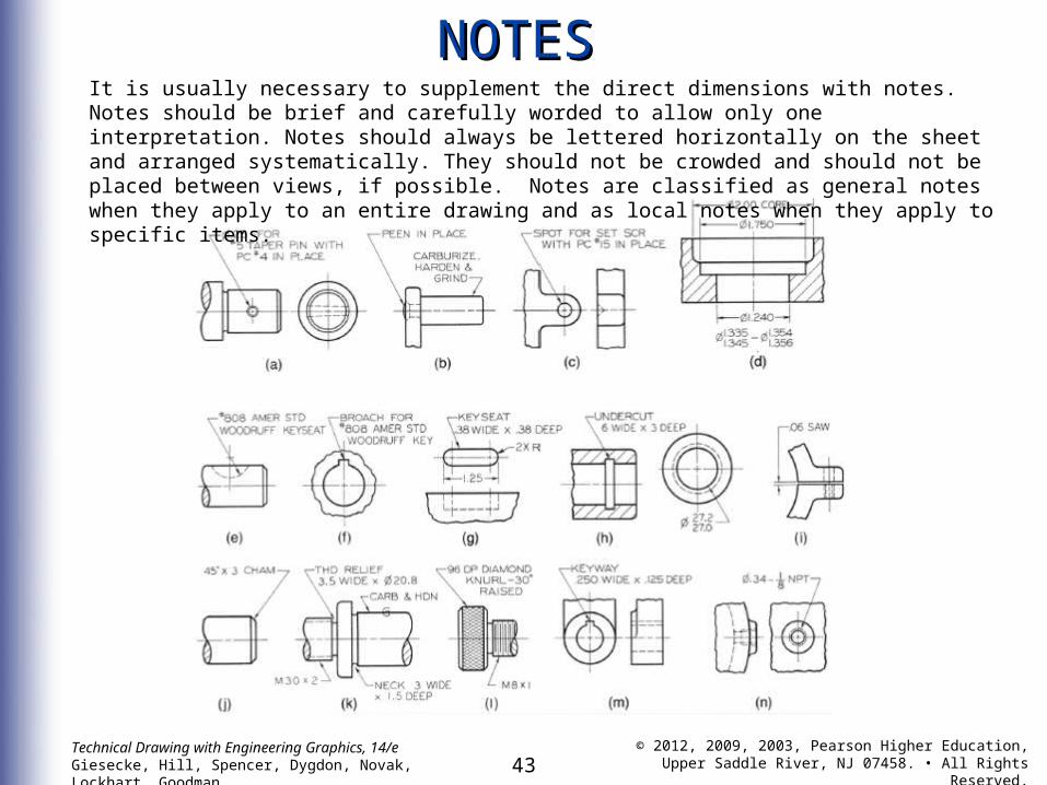
NOTESNOTESIt is usually necessary to supplement the direct dimensions with notes. Notes should be brief and carefully worded to allow only one interpretation. Notes should always be lettered horizontally on the sheet and arranged systematically. They should not be crowded and should not be placed between views, if possible. Notes are classified as general notes when they apply to an entire drawing and as local notes when they apply to specific items.