Embed Size (px)
Citation preview

8/12/2019 Automatic Power Factor Control
http://slidepdf.com/reader/full/automatic-power-factor-control 1/20
Internal guide:Mr . S.M.M.MUDASSIR
Associate Professor , EEE Dept , DCET
By
1. MOHMMED IMRAN Roll No:1603-107-34024
2. MOHAMMED MUJAHED KHAJA Roll No:1603-107-34033
3. S.MOHAMMED OSMAN Roll No:1603-107-34035
8/12/2019 Automatic Power Factor Control
http://slidepdf.com/reader/full/automatic-power-factor-control 2/20
*
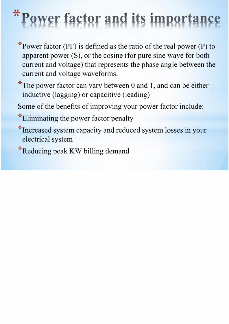
*Power factor (PF) is defined as the ratio of the real power (P) to
apparent power (S), or the cosine (for pure sine wave for both
current and voltage) that represents the phase angle between the
current and voltage waveforms.
*The power factor can vary between 0 and 1, and can be either
inductive (lagging) or capacitive (leading)
Some of the benefits of improving your power factor include:
*Eliminating the power factor penalty
*Increased system capacity and reduced system losses in your
electrical system
*Reducing peak KW billing demand
8/12/2019 Automatic Power Factor Control
http://slidepdf.com/reader/full/automatic-power-factor-control 3/20
*
*The project aims in maintaining power factor near to 1 with the
help capacitors banks which is disturbed after introducing
inductive loads into the system.
*The method used to correct the power factor is installing ofcapacitor banks.
*Installing capacitors decreases the magnitude of reactive power
(KVAR), thus increasing your power factor.
*Incase of balanced circuit, all the energy released by theinductor is absorbed by the capacitor.
8/12/2019 Automatic Power Factor Control
http://slidepdf.com/reader/full/automatic-power-factor-control 4/20
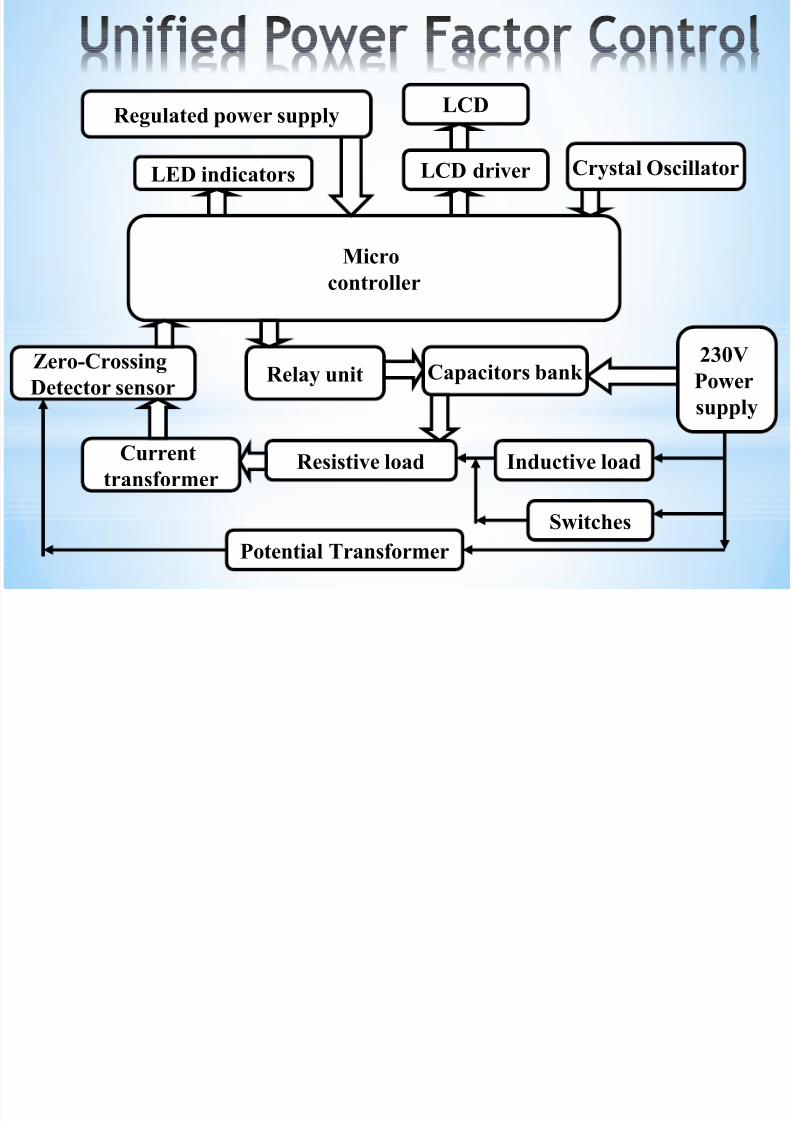
LCD driver
LCD
Micro
controller
Regulated power supply
Relay unitZero-Crossing
Detector sensor
LED indicators Crystal Oscillator
Capacitors bank230V
Power
supply
Resistive load Inductive load
Switches
Current
transformer
Potential Transformer
8/12/2019 Automatic Power Factor Control
http://slidepdf.com/reader/full/automatic-power-factor-control 5/20
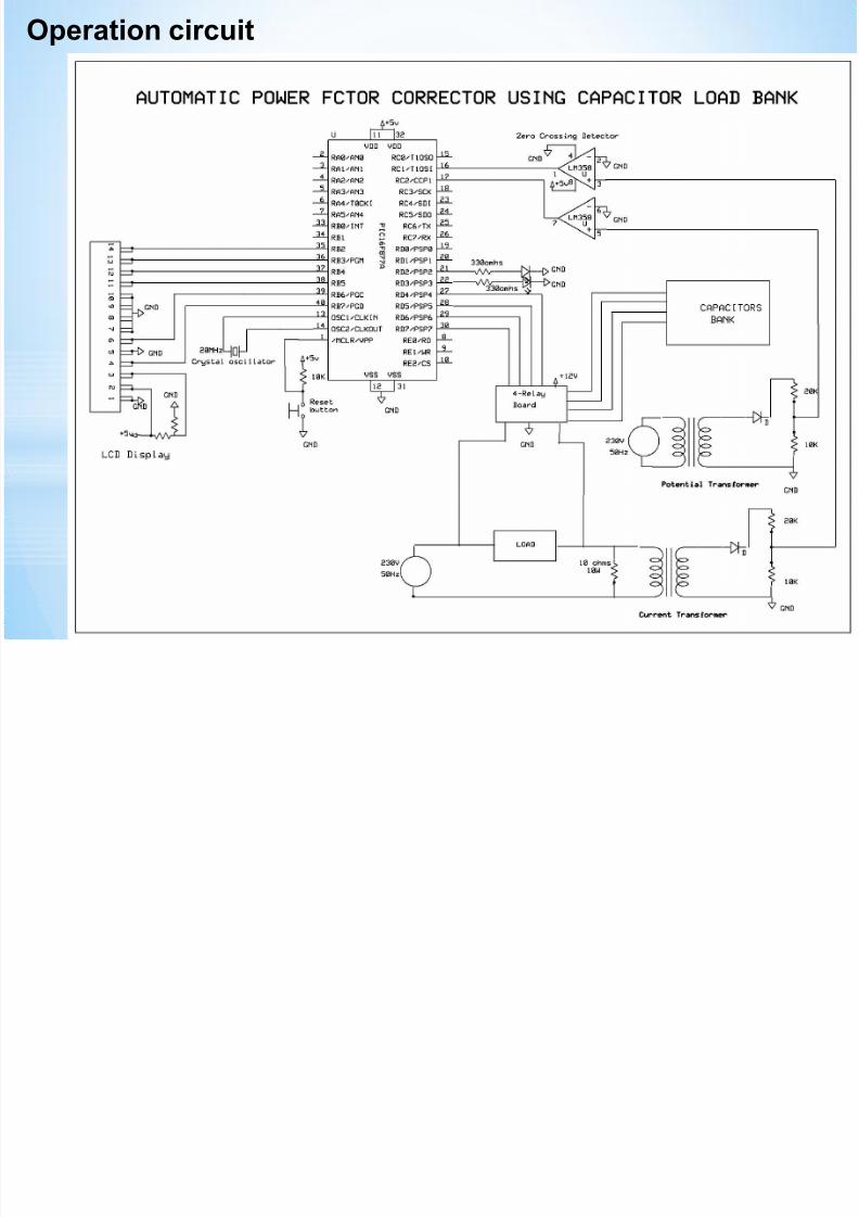
Operation circuit
8/12/2019 Automatic Power Factor Control
http://slidepdf.com/reader/full/automatic-power-factor-control 6/20
*
*Microcontroller
*Regulated Power Supply
*Crystal Oscillator
*LED indicators
*Potential transformer
*Current transformer
*Zero crossing detector
*Relay unit
*LCD (Liquid Crystal Display)
8/12/2019 Automatic Power Factor Control
http://slidepdf.com/reader/full/automatic-power-factor-control 7/20
*
*Microcontrollers are “special purpose
computers”.
*The Microcontroller includes a CPU,RAM,ROM,I/O ports, Timers etc.., like a
standard computer, but on a single silicon chip.
*Microcontroller based systems are designed to perform a specified task.
*The Microcontroller used in the project is PICMicrocontroller developed by MicrochipIncorporation
8/12/2019 Automatic Power Factor Control
http://slidepdf.com/reader/full/automatic-power-factor-control 8/20
*
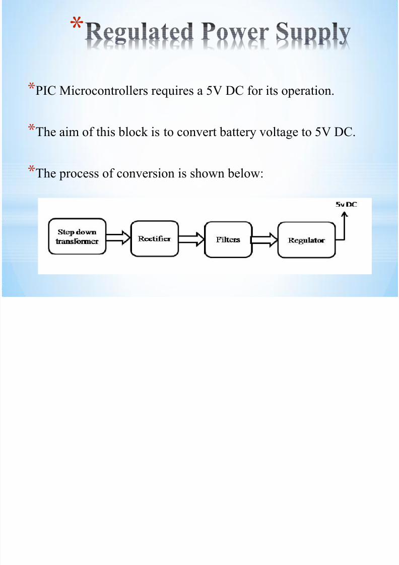
*PIC Microcontrollers requires a 5V DC for its operation.
*The aim of this block is to convert battery voltage to 5V DC.
*The process of conversion is shown below:
8/12/2019 Automatic Power Factor Control
http://slidepdf.com/reader/full/automatic-power-factor-control 9/20
*
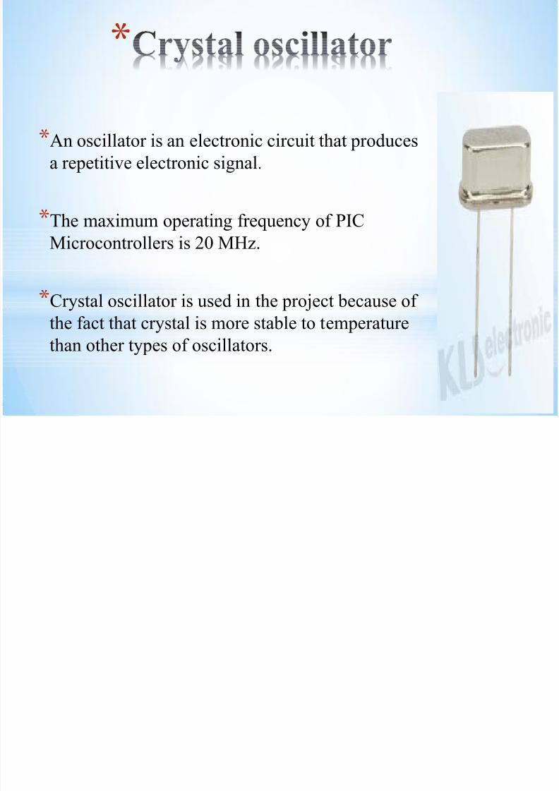
*An oscillator is an electronic circuit that produces
a repetitive electronic signal.
*The maximum operating frequency of PIC
Microcontrollers is 20 MHz.
*Crystal oscillator is used in the project because of
the fact that crystal is more stable to temperature
than other types of oscillators.
8/12/2019 Automatic Power Factor Control
http://slidepdf.com/reader/full/automatic-power-factor-control 10/20
*
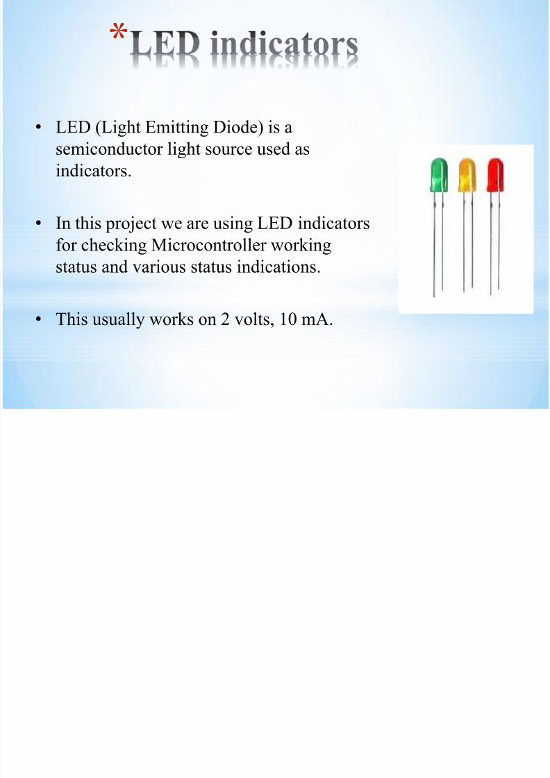
• LED (Light Emitting Diode) is a
semiconductor light source used as
indicators.
• In this project we are using LED indicators
for checking Microcontroller working
status and various status indications.
• This usually works on 2 volts, 10 mA.
8/12/2019 Automatic Power Factor Control
http://slidepdf.com/reader/full/automatic-power-factor-control 11/20
*
*We are making use of PT (potential transformer) for
capturing the zero-crossing point of voltage wave
form.
*PT converts the high voltage AC to a low voltage
measurable quantity.
*PT of type step-down transformer.
8/12/2019 Automatic Power Factor Control
http://slidepdf.com/reader/full/automatic-power-factor-control 12/20
*
*CT are used for current measurements.
*We are making use of CT (current transformer) for capturing the
zero-crossing point of current wave form.*CT is of type step-up transformer.
8/12/2019 Automatic Power Factor Control
http://slidepdf.com/reader/full/automatic-power-factor-control 13/20
*
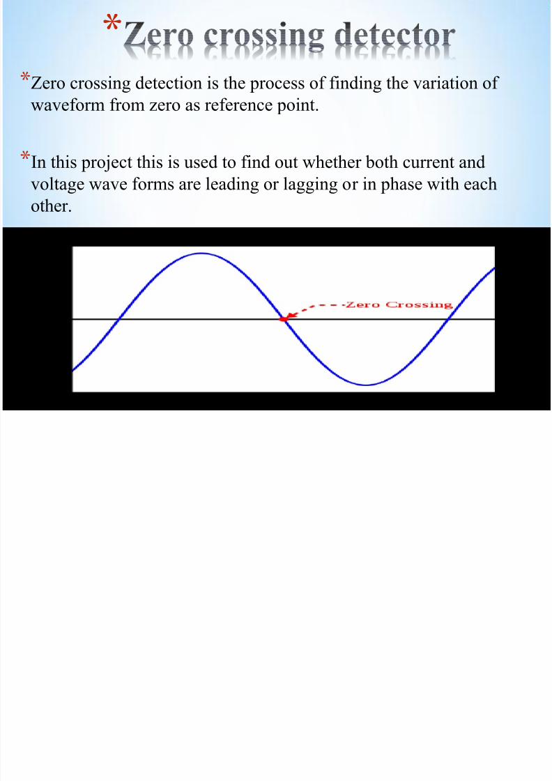
*Zero crossing detection is the process of finding the variation of
waveform from zero as reference point.
*In this project this is used to find out whether both current and
voltage wave forms are leading or lagging or in phase with eachother.
8/12/2019 Automatic Power Factor Control
http://slidepdf.com/reader/full/automatic-power-factor-control 14/20
*
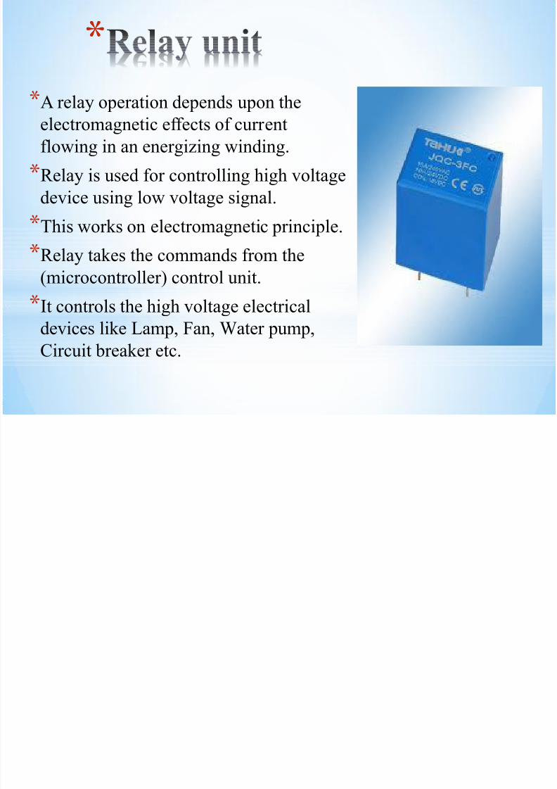
*A relay operation depends upon theelectromagnetic effects of current
flowing in an energizing winding.
*Relay is used for controlling high voltage
device using low voltage signal.
*This works on electromagnetic principle.
*Relay takes the commands from the
(microcontroller) control unit.
*It controls the high voltage electrical
devices like Lamp, Fan, Water pump,
Circuit breaker etc.
8/12/2019 Automatic Power Factor Control
http://slidepdf.com/reader/full/automatic-power-factor-control 15/20
*
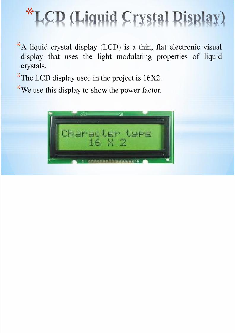
*A liquid crystal display (LCD) is a thin, flat electronic visual
display that uses the light modulating properties of liquid
crystals.
*The LCD display used in the project is 16X2.
*We use this display to show the power factor.
8/12/2019 Automatic Power Factor Control
http://slidepdf.com/reader/full/automatic-power-factor-control 16/20
*
Advantages of power factor correction includes:
*Saves money on utility bills* Increases internal electrical system capacity
* Improve voltage drop at point of use

8/12/2019 Automatic Power Factor Control
http://slidepdf.com/reader/full/automatic-power-factor-control 17/20
*
*Investment is more for extra capacitors.
*The control circuit will draw some power
continuously.
8/12/2019 Automatic Power Factor Control
http://slidepdf.com/reader/full/automatic-power-factor-control 18/20
*
*Industry motors.
*Irrigation pump sets.
8/12/2019 Automatic Power Factor Control
http://slidepdf.com/reader/full/automatic-power-factor-control 19/20
[1] Narendran, N. “Requirements for solid-state lighting” Conference on
Lasers and Electro-Optics, 2004. (CLEO). Vol 1, 2004
[2] DOE Solid-State Lighting CALiPER Program Summary of Results:
Round 7 of Product Testing (PDF). U.S. Department of Energy. February2009.
[3] Wei Xiong ; Stankovic, A.V.; Nerone, L.R. “Modeling and Design of L-Complementary Self-Oscillating Class D Inverter With Output VoltageClamping” IEEE Trans. on Industry Applications, vol. 49, no. 2, April 2013,
pp. 731 – 738
[4] Cosby, M.C., Jr. Nelms, R.M., “A Resonant Inverter for Electronic Ballast
Applications” IEEE Trans. on Industrial Electronics, vol. 41, no. 4, Aug 1994, pp. 418-425
[5] Kazimierczuk, M.K. ; Szaraniec, W. “Electronic ballast for fluorescentlamps” IEEE Trans. on Power Electronics, vol. 8, no. 4, 1993, pp. 386 - 395
*References

8/12/2019 Automatic Power Factor Control
http://slidepdf.com/reader/full/automatic-power-factor-control 20/20