Embed Size (px)
Citation preview
-~- --.-----.---~
&-~ AUTOMATIC o OVETAI LER OPERATING INSTRUCTIONS
~~ 11 I' .OA).W1R, SIDE
l:.R""'" BRI~ J " "' il 'PP,I~ ~t~
YI~llt.A1.. ;:!)t~a ----_._._-......,- ~ A..OJ\J!5TMe:..,.,.
~ ,,. ... ~I..E
, 'UoiGS'i»\...A"T1 " !Tt! If "",! I! ~ If ~ I ~T><£.1 / """""'g ",OW'T
( . f ~ r • :
GAu..IO€R, ~lVING ~U~I'(\. --
M0:O~
---.J '".~
8 ! ClfT~;~'~ ... ", PJllj hn d)' IltfI AOJUATMIWT V ~
TYPE AD Mkl.TItID
~D""",® 1ofA.1oK) nw .... FEte lPEEO-
CR.to.MO CO~QI.
P'l-JIUMA'1'IC Mr~IN'A ONI.."I'
R S, BROOKMAN LT~ I'brlcsicle HIor.4s L.EICESTER~HIRE
~
0101,"'0>-\,\
ENGL.AND
{FJtOt(£ AOJ'U$TMCk'T
, FI'T ~\.I'"TMon ,
, U,1oI'bR.1Jt.4
A OT H LEY c ,-1)
, "Sc)?201
"
www.Dalt
onsW
adkin
.com
www.DaltonsWadkin.com
www.DaltonsWadkin.com
/? / '
... ' X::> / " //?/
~'-'''''--I1'''-'+.,,4,,'-./'+-,.Q~ ':<''. / ;.. ./ / '~ENc.~J.; Of PI" .
~ O£P~H
£MIl'RGEt-lC"f 1 FEEO Re.I.EASE
AUTOMATiC. FEED 2 S'fA.P.TlItolG Kt.lOe,
ADJUSTMENTS
AlSC c.ol"respondih9 nuts at oppo&i~e. end of me.cn~ne..
r~"UT~
t!Y.I. AU'TOMATIC. F!.e.O t)
5T"'I>,~INr. ~~No\'E "
DOVE.TAII...ING
T'fPES
E
www.Dalt
onsW
adkin
.com
www.DaltonsWadkin.com
www.DaltonsWadkin.com
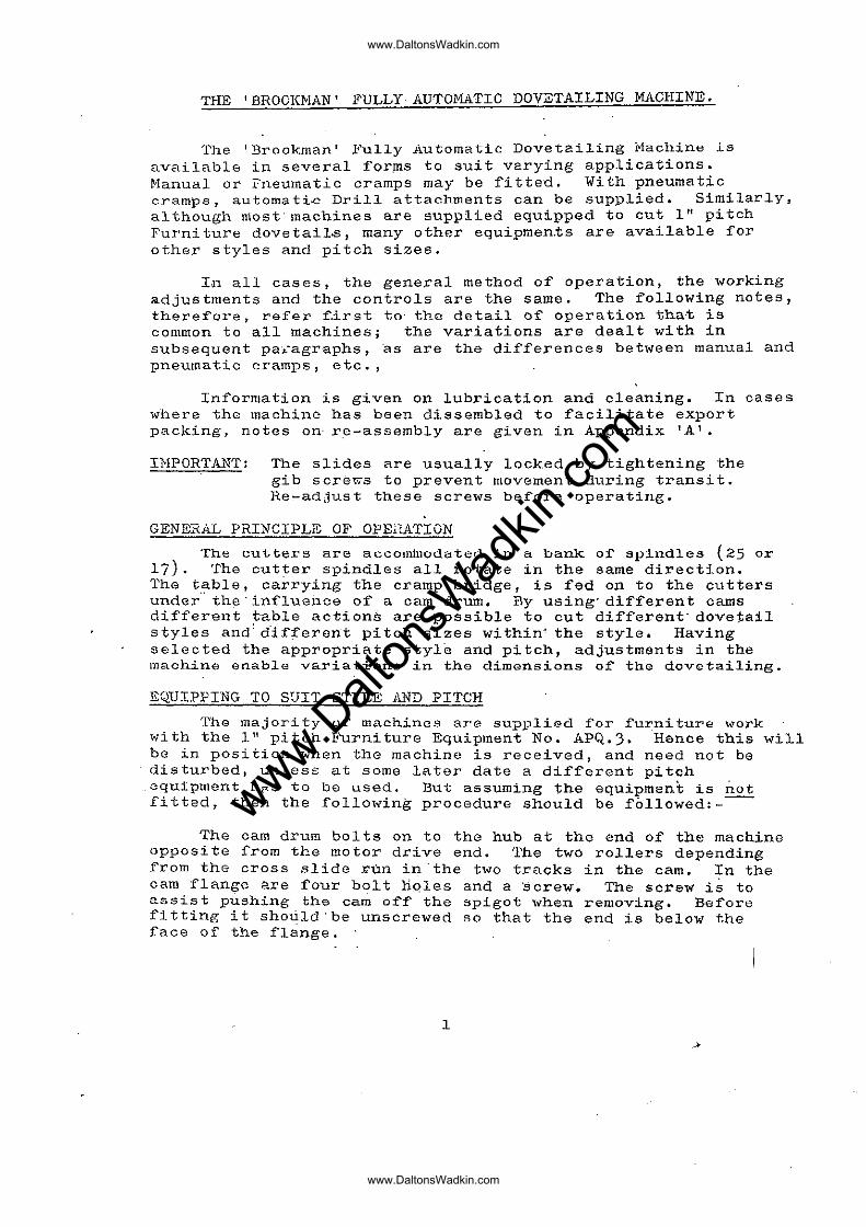
THE 'BROOKMAN' FULLY,AUTOMATIC DOVETAILING MACHINE.
The t Brookman I Ii'ully Automatic Dovetailing j:·1achine ls available in several forms to suit varying applications. Hanual or I"neumatic cramps may be fitted. With pneumatic cramps, automati~ Drill attachments can be supplied. Similarly, although most'machines are supplied equipped to cut 1" pitch Furni ture dovetails, many other equipmen,ts are available for other styles and pitch sizes.
In all cases, the general method of operation, the working adjustments and the controls are the same. The following notes, therefore, refer f.irst to' the detail of operation tha·t is common to all machines; the variations are dealt with in subsequent pa,-agraphs ,as are the differences betl<een manual and pneumatic cramps, etc.,
Inf'ormation is given on lubrication and cleaning. In cases where the machine has been dissembled to facilitate export packing, notes on: r.e-assembly are given in Appendix 'A'.
IMPORTANT: The slides are usually locked by tightening the gib screv.s to prevent movement during transit. Re-adjust these screws before operating.
GENEi~A.L PRINCIPLE OF OPEi'LATION
The cutt.ers are accoIlll11odated in a bank. of' spindles (25 or 17). The cutter spindles all rotate in the same direction. The table, carrying the cramp bridge, is fed on to the cutters under" the 'influence of a cam drum. By using'different cams different t'able actions are possible to cut different'dovetail styles and'different pitch sizes within' the style. Having selected the appropriate style and pitch, adjustments in the machine enable variatiops in the dimensions of the dovetailing.
EQUIPPING TO SUIT STYLE ill,D PITCH
The majority of' machines are supplied for fur:niture work with the 1" pitch Furniture Equipment No. APQ.3. Hence this will be in position when the machine is received, and need not be disturbed, unless at some later date a different pitch
.equipment hp.s to be used. But assuming the equipment is not fitted, then the following procedure should be followed:---
The cam drum bolts on to the hub at the end of the machine opposite from the motor drive end. The two rollers depending from the cross slide ~un in the two tracks in the cam. In the cam flange are four bolt holes and a screw. The screw is to assist pushing the cam off the spigot when removing. Before fitting it should 'be unscrewed so that the end is below the face of the flange.
1
">
www.Dalt
onsW
adkin
.com
www.DaltonsWadkin.com
www.DaltonsWadkin.com
On .th.e··ri._m. 6·f the Cati.l is a s~<?p; this goes towards tho nl':-""I..chinc and uppermost. This 1'iill bring· the scrcw uppermost also and the head outwards. Slip the cam over thE: hub, oIfer up on to the rollers; the tracks are cut away at the entry point to assist this. All the cams .have the same track centres at this point,' so that the rollors will be in the correct position to acc~pt anoth6r ·cam when anA has boen removed. If the rollers are not at the· right centras push the table towards the cut tor spindles to decrease, and away to increase. The cross slide \ViII move bodily taking bottl rollers as a canl is pushed en or off.
Make suro th;·l t the flang0 Elne hub faces are the flange locates correctly on the hub spigot. four bolts, using the box spanner provided.
clean, and that Secure with the
Next fit the finger plate ,"hich locates in the re·CGSS .in the front of the table, behind thG cutter spindles and· under the cramp bridge. Bol t in position by the five scre,,,s, using the Weasel spanner provided.
Alw~ys f~t this plate before· screwing in the cut~ers, or the latter will obstruct access.
The cutters screw is right handed. The tommy bar provided fi ts in to the hole in the rim of' the grinder driving pulley bGtween thH motor and the machine. Then the cutter spindlE.:s can be rotated or held stRtionary_ The cutters are·pro.vided with fJ_Rts \vhicb fit thQ jll Gap spann.er.
On a 2S spindle m~chinG, wi th the norm.al 111 pitch equipment and the ill pitch, every ~pi~dle accepts a cutter. On ~II pitch however, tbe cutters are spaced in every other spindl~, and on I-fr" pi tcb. eVGry ·third, star.ting fror:1 the end s.t='indle. in both. cases. Spindle plugs "ro provided to blank off the spindlGs not in use.
On a 17 spindle machine every spindle accepts a cutter for both il' and It'' pitch.
FEsn CONTHOLS
Before Gng~g{ng'~he feed ensure that gib screws tbat may have been lcicked to prGvent slide Inovcmont in transit, are readjus tGd. They should b9 l..lns crewed, c:lond then re- tightened, full finger tight, and locked by the nut.
Th0 m8chine he-,s tl~roe rates of nutolTIntic feed. Looking at tl1.C :t'ront of the machine, th~:: .knurlod knob (4) ·on the 101'ior right projecting spindle is the s~eed ch2nge. Right in ~s thG slow feod, right out the fastJ and intermed:Lc:tc.midway. The squared shaft (3) to tl"1n ·Iaf't accepts·tho·hand o.rank for testing .. The table can be fed by hand to check a setting. (It may be necess~ry to ·use this when fitting a cam, ~s above, to bring t~e bolt holes into the correct alignment).
2
www.Dalt
onsW
adkin
.com
www.DaltonsWadkin.com
www.DaltonsWadkin.com
It is advisable, especially until the operator is fully proficient, to check settings by this hand rotation to ensure tha tiutt~rs clear,·before engaging the mechanical feed.
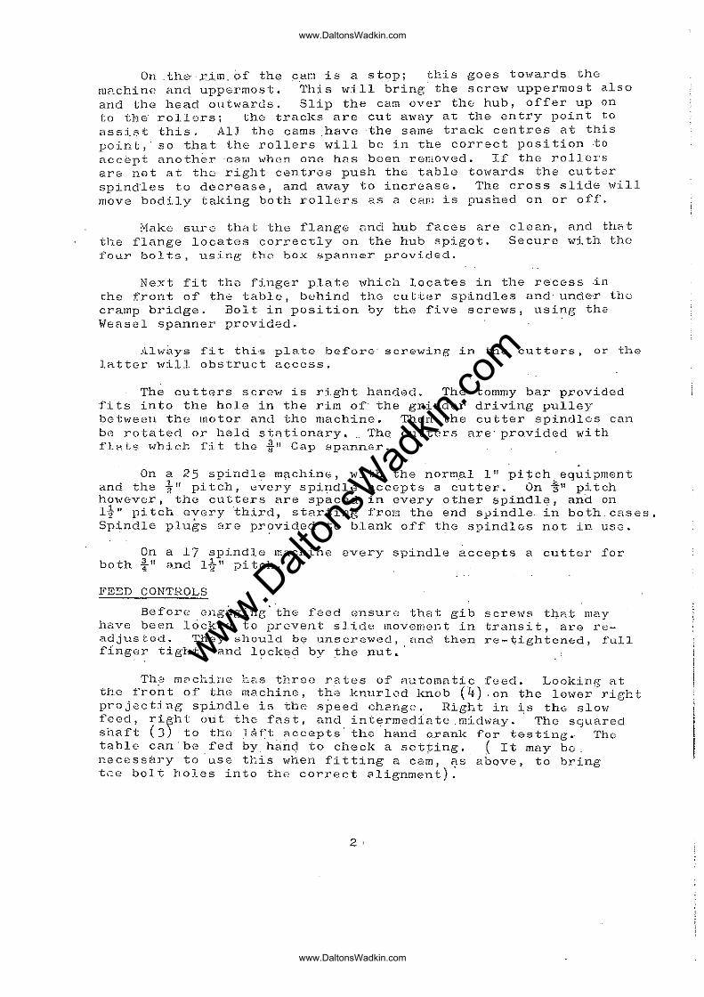
The feed is engaged· by the cross tee handle (2) which is pu~led: This is duplicated. at the rear b{' ~ flat headed knob 1,lnch lS pushed. An emergency release (1) lS provided to disengage the feed, at any part of the cycle, should this become necessary.
ADJUSTMENTS TO DETERMINE DIMENSIONS OF FURNITURE TYPE (HALF LAP) DOVETAILS
. LENGTH OF PIN
. The adjustment for the length of pin "c", i.e .. the amount the cutter h~ad extends above the table level, is by the two Screws F.F. The frame carrying the cutter' spindles ;i.s cramped in position by Screws G.G. It is suspended on' Screws F.F. To adjust, rele<'\se Screws G.G. and turn Screws F.F. clockwise to raise and" anti-clockwise to lo\V~r. Screws F .. F. are provided wi th indicfltor scales so that their movement can be synchronised. One complete turn is 1/16".
When lowering the frame drops under gravity. It may thGrefore be necessary to apply pressur. to the two screws to assist the downward movement. It is advisable to adjust below the po:!!;.tion required, and then to bring up again to the desired level.
Always re-tighten Screws G.G. after adjusting.
STROKE ADJUSTMENT
The maximum stroke of the table is determined by the cam. This can be shor·tened 'below the maximum by adjusting Screw E .• Thisscre" moves the Adjuster Slide, the po si tion of which is indicRted by a scale. In P9s'i.tion 1110" the table will tra.vel the maximum cam stroke. The' sl.i~le can be adjusted" to any position down to the minimum at "0".
and The slide is locked by Screw ID'. To adjust slElck Screw iD'
turn ScrsN '£'. Re-tighten 'Dt after adjusting.
This adjustment makes bn.th dimensions "aft and H·b ll equally greater or sm8..~l.cr to accommodRtG diffGrences in th0 thickness of the wood on which the pins arG cut. Do not confuse with the neit adjustment for depth.
NOTE: This' adjustment refers to'Furniture typo Dovetailing only. When cutting Box Dovetail'ing and Corner Locking the adjustment is set at ·maximum "10".
J
www.Dalt
onsW
adkin
.com
www.DaltonsWadkin.com
www.DaltonsWadkin.com
DEPTH
fiCjjustment: f.or flush fit or otherwise ~ Screw's f B I and I C I arc horizontally opposed on a vGrtical pin ~nd ShOl11rl b~ moved in conj~nction o~e with the other. If 'E' is unscrewed one turn, rc' should be screwed up onb turn. The curved indicator scale shows a position IIO!' betwean the words "deep'l and I'shallow!', With the Fointer 'J' adjusted to this zero position the resulting .joint should knook together flush. The stroke 2.djustment and the tightness of' the fit, however, h?,ve some effect' on this 2.nd slight finAl adjustment will be necessary.
Supposing when 'a joint is cut, the pins stand proud, ';1.djustment is made as follo\4ls: Release the Cramping Scre1\' 'D', and unscrowing Screw 'C', tighten Screw 'B', causing the Pointer '.J' "to move towa~ds the word "Deep" on the scale. "Lock 'B' against 'C' and·re-tighten 'D'~ I~ the reverse is required release I Brand tighten le 1 to move pointer towards !'Shallow".
The adjustment \vill increase Ita I' to the same extent that it "deCr0[l.SGS "bl!,' and vice "versa. "a" plus "bit rem2.ins constant.
This adjus tmen t is very fine." A quarter" turn of' either screw liB" or "C" will m2.ke considerahlG difference to the joint. The scale can on"ly be used as 8. guid .... "} , and re-setting to m~rks is not practicablG.
,WJUSTMENT FOR FIT
Highering or lowerirlg th~ cutters, the difference between thick and thin drawer Sides, hRrd and soft timbers, cutter wear, and the requirements of the" particular ''lork, all affect the fit ut' the jOint. The precise .fit l'eCjuil'ed can be obtilined by
... adjusting Screw" "A". The upper hexagon nut is for locking 2nd should be unscrewed cle::u' before C\djusting. The lower knurled nut makes the actual adjustm~nt. ScrE:wing left handed will tighten the j ain t, right hc~nded will slHclcen. (Note: I~12.chines -..vi th SGrial Nos. 5203 and prior h:,=--.vG adjusting scrEo;n.;s which turn right handc:d to tighten the ,joint and left handed to slnckGn.)
If difficulty is experienced in turning, first ensure that thG h8xagon nut "is slac!«"l~d \Yell away, then' using the crank handle (sec Feed Controls) rock the handle to and fro a. h2.1f turn whilst "ayplying" Cl Lu"rnlllg InOVemeIl t.; t.;o the knuI.'led nut.
If the adjustmerlt is screwed to the limit and the joint is still sla.ck then it '''ill be necessary ei thar to higher the cutters slightly or to use smaller cutters. As mentioned above the cutt'Jrs become smaller ",i th grinding and if difficulty is experienced obtaining R fit on short pin work (Dimension 'le") then keep the worn cutters for this and" use the newer cut tors on longor pin work. (See Appendix I'BII for cutters available.)
4
www.Dalt
onsW
adkin
.com
www.DaltonsWadkin.com
www.DaltonsWadkin.com
The foregoing information \ViII enable the more general purpose dovetailing 1:;0 cut. Th" notes thRt follow give points on the "Ivider applications.
AI' ... flYs remember J hF,ving adJusted, to re-tighten the locking nut~ 2nd scr0Ws! A. D. ind G. G. "
REBJ' .. TED D,,;.NER FRONTS
The dovetailing of Rebated Fronts is similar to the normal flush f'i t typ" exoept that the Stroke Adjustment (Scre,; E) will be placed to give +onger stroke than is norm2.11y required f'or the thickness of drawer sides. The ndditional length is necessary to spAn the depth of the rebate~
The Depth adjustment must be mov~d towards DEEP, as in effect a very doep cut is necessary in the drawer front. Having made this (1djustUlent it is advisable to check the cam cycle by using the hand crank to ensure that the cutters do not foul the finger plate,
In cases where the cu-t;;ting of the rebate is not regularly accurate it is avisable to employ a special finger plate with projections against which the shoulder of the rebate will locate. This plate can be specially supplied! or the standard plate can be drilled to accept smRll dowel pins.
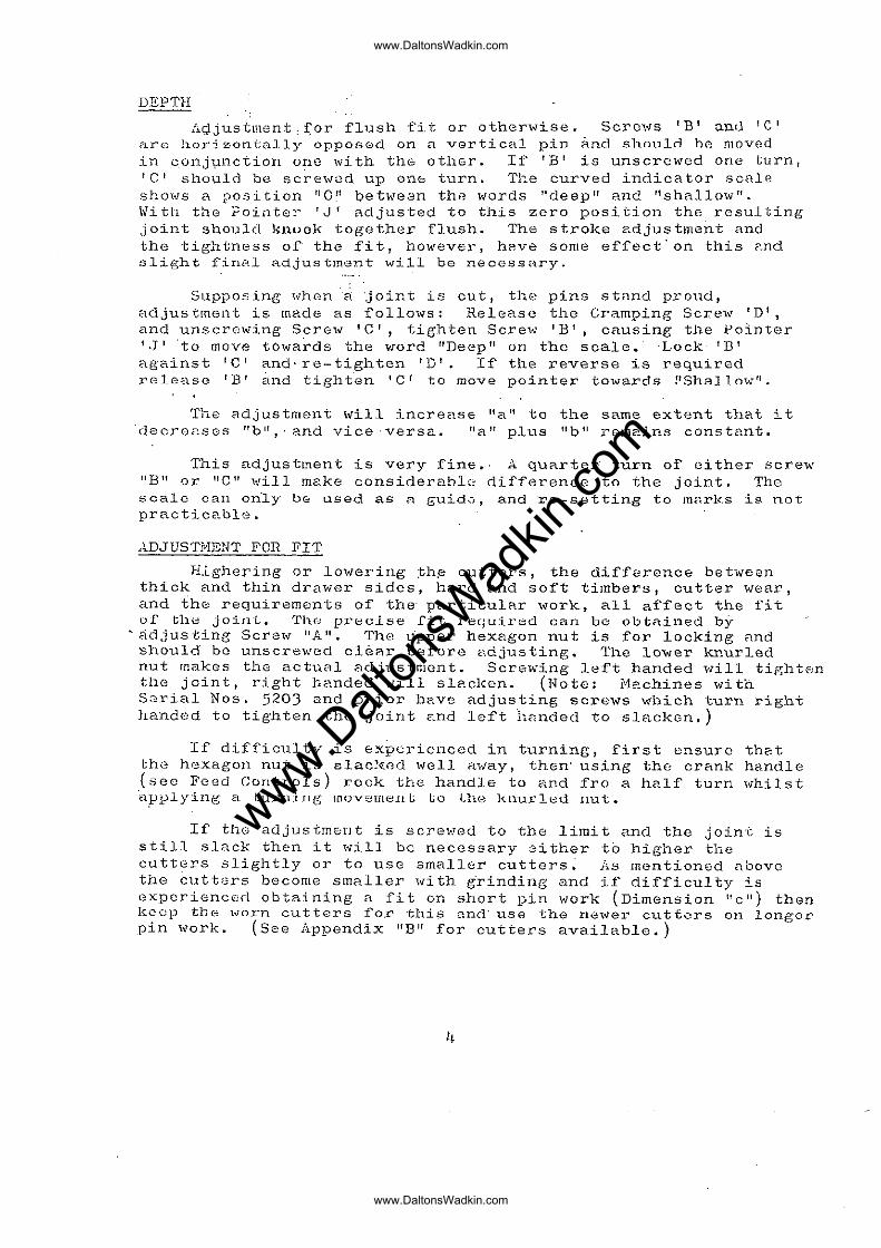
SECRET DOVET,ULING
S·ecret ·dovetailing is achieved by cutting the whole of the furni ture dove/tailing action into each piece of wood. To do th;:is the tl.,ro components of the joint are placed in the machine side by.side. The horizont8.1 wood does not butt "UP behind the vG.I"'tic<:'I.l piece, bu t is ple.ced along side. with the outer edge aligned wi th the "outer face of the vertical "piece.
Jdhen producing it is probably advisable to cut all the verticFl.l pieces a·t onG operation, and the horizontal at another. When cut"ting "the horizontal pieces, 8. s'top ce:q. be clamped pGrmo?,ncn tly in tho vertical cramps agfl.inst Wh'lCh 'to locate.
The Stroke Adjustment v.lill hRve to be shortened, and the Pointer' JI on thG Depth /.I.djustment moved oVer to "SECR3T tI on the sc~le ~ The Depth J~djustmGnt will be" used in the normal way to obtain a flush fit, and the Fit Adjustment screw A operates in the ordinary way.
If the material is "mitred the cutters wi21 have to be the amount of the mitre when cutting the vertical" pieces. mitre is very deep it may b~ necessRry to use cutters with shanks.
5
raised If the extended
www.Dalt
onsW
adkin
.com
www.DaltonsWadkin.com
www.DaltonsWadkin.com
m::NT . ~ CURVED HORK
The rU8.Chine has two provisions -for bent and curved 'iv-ork. The ceT1trc~ of the tc1ble can be removed to allow the curve to pass belOW normctl table level. The cramps are provided 'J,.;i th swivel or removable pads to suit the direction of the curvo.
To renl0Ve the centre piece unscrew the -two hexagon bolts rec~::.'3sed into the work table. The middle: section 12" \vidE: can then be removed. If the curve is modGrato the centre piece cRn be left in position but th8 face lowered below the normal table lev~l by adjusting the sto!} screw at the rear. This same sc.rew will enable the centre piece to be adjusted above normal table levGl if necessary.
The well in thG table revealed by the removal of the centre piec8 has h,O horizontal pads drilled and tapped tu Whih10rth. Shaped saddles to pasi tio.TI thE! woods C':Fln bc:) screwed to th(,s(:.
Practically (~vcry curved , ... ark application h8S its O\'-ln
problems. Extended Gutters, special finger plates, etc., are aV2.ilable to. accommoda,te this work. It is usually cheaper, however, to make wooden support saddlGs than to purchase a brass finger. plate for one .pA~ticular bent work job.
CRAl-IPS & "ORK FENCES
A full sat of work location fences is provided. two pairs of fences on both the vertical face of the and on th.e horizontCll face of the wo·rl<:. table. These also carry rule. scal~s to assist in positioning the
There are cramp bridge two faces
fences.
It will be observed that thb~e rule scales are zerobd on the centre line of the machine. It is necessary to work outwards from the centre l~ne to keep the work correctly I'handed". For GXRmple ono pair of the table, br horizontal, fences arc usually placod on the 12!! mark, one each side of the work table. A drawer front, ..,h&n being dovetailod will be offered up with the rac~ odge to the right·hand i'ence, and the::n it will be flhanded!' OV2r and offered to the left hand fence.
ha alrearly ind~catGd·, it is usunl to keep ono pa£r of fences a·t the fulles t width of· the: table, and bridge, faces·. This Enables any width of board l"!.P to 1211 to be worked· without altering the fence positions except for very minor adjustments. Should the boards be lesti than 6!1 wido the remaining fences are placed, back to back, ·o:q thE: centre lino, when four joints eRn be d6vot~iled at each table op~ration. For widths over 6" but less ihan 8 11
, the centre .fences should be spread to approximately the 4" marks, when three joints can be dovetailed together.
6
www.Dalt
onsW
adkin
.com
www.DaltonsWadkin.com
www.DaltonsWadkin.com
The precise setting of' Cl fence depends upon the €:JX:1ct \.,idth of the work to be dovetailed and the exact cbAracteristic raql1ircd of the final joint • . Much will depend upon the user's requirements and decisions will come morG 8nsily ?s experience: is gainGd in using the machine. The general rule, however, is th"It the table, or horizontal, fence is placed on the full pi tch dimension and the vertical, or bridge fence, half a pitch from
'this. Fcr example on the 1" pitch dovetailing, «hich is the most commonly used, the table fence «ill be placed, with the edge ngHinst \..;hich the wood will locate! on the full inch mark, say 12". The bridge fenco \-1i11 then be ,played on 1.1:tn or 12t" j
that is half.a pitch of'f~ This will cause the two edges to align :"hen the joint is knocked togeth8r. Moreover, the table fence being on the full j.nch m8rk 't-.rill cause the edge of the \<lood Lo fp.ll plumb along the brass supporting fing,~r Rnd remdin so~id wood. If this rule is not followed th6 upper or lo«er ~orner of R jOint, or both, will have half a dovetail pin showing.
1Vhen working pit.ches other than 1" the same rule "pplies except that the table fence positions become multiples of the pitch (the f'ull inch marks were multiples of' 2 ft
). In any case "im to keep the edge of the wood th"t m2tters most, usually the upper edge of a drawer fron~, to fall plumb along the centre of the fingc.,r.
To 2ssist in keeping the vertic0.1 waods up to the fencE:s prior to crahlping, spriI,1g fences are provided. These should bG plnced -to give light pressure on the edge of' the ,,.rood to hold it against the ferice. They have no function af1;er cT2:mping, and when the width of' the «oods absorb the full ,"idth of the bridge face they h8ve to be dispensed with.
1Vhen cutting very 'vide stock up to the full capacity of the ma6hine, the horizontnl' f6nces may be roversed and the short end will then pass beh~nd the cramp bridgG foot.
HiJ~Uri.L C~{"J",P BRIDGE
The manuc-"\l Cl"'c:.rI1,P bridge has on!3 long ecc'Jntric cr;::unp to secure the vertical pieces of wood, and four independQnt cramps to secure the horizontal pieces.
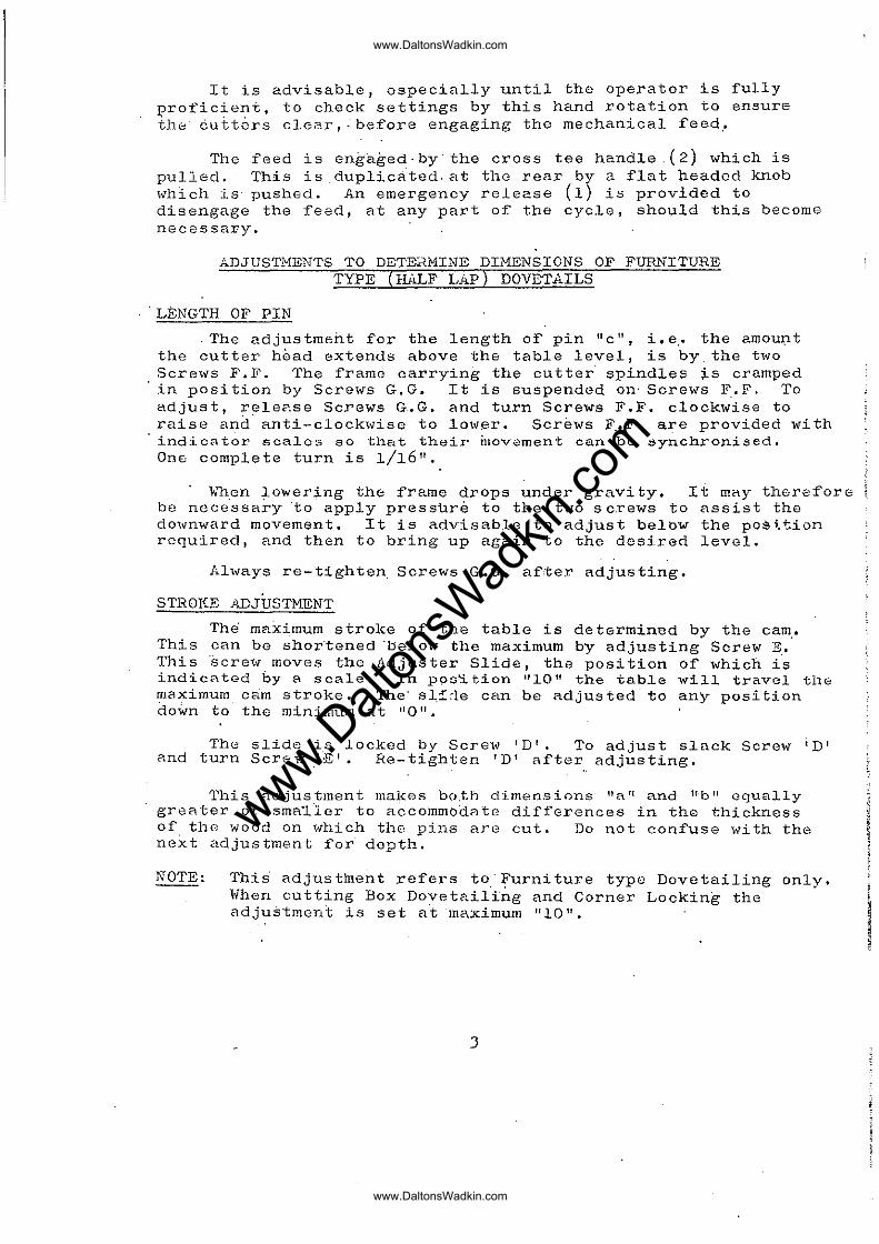
The· vertical craiilp is ndjusted by nilts on horizont21 screws ~t 0ach GIld of the bridge. ~ simpla method at adjusting ~s to place in position a piec0 of wood of the thickness to be crnmped; place the oper~ting hAndle vertic~lly and then push the roller p.nd cramping l::-late on to th0 \.;ooe1. Screw up the adjusting nuts and it ,,;ill b8 found th?,t the correct tightness of cramping results ~hen the hfindle i9 pushed home. It 1s aUvisable to adjust this cramp RS close ~s is po~sible consistent ~ith the eccentric gripping satisfactorily. There is f\ dnnger, if' El ,.,ride gap is lsft, of the wood missing the brass finger plate when, the opere.tor not r8alising, the «ood will be jammed behind the plain portions of the: cutt8rs and brealcege of the CRrn tr,::verse rollers results.
7
www.Dalt
onsW
adkin
.com
www.DaltonsWadkin.com
www.DaltonsWadkin.com
The horizontnl crflmps aro adjusted by four vertical scrcn"s. They should be set so RS to give the mRximum cr8.mping with the hr~nclle just above:" horizontal.
Lock nuts L'..re providod" on 2.11 the (1djustmanis.
Al+ tho crRmp faces hnve rubber and wood pads wh~ch cnn be roplnced when worn, or Inade to ~pecia]" sh8~es if necessary.
PNEmLi.TIC C:;{AMP BRIDGE
The Pneuma tic Cralilp Bridge has two bonks, of eight cramps each, oper~ting in the vertical and horizontal directions. The cramps are closed by foot pedals and are releasGd automatically. This is dealt 'i.,ith in Cl lcter parngraph on. Pneumatic type machines.
Each cramp has an independent air stop valve so that it can be put out of action to conserve air ,.;hen possible! \fuen Cl cramp is in use the stop valve should be well open, three complete turns of the screw.
The cramps holding the horizontetl ·weods require no adjustment. The trav.c:l is ample to take up varietions in the thi ckness of wood. The cramps holding the vertical wood, ho,,,evl..';r I
must be adjusted to suit variations in thickness not so much to facilitate cramping as to prevent woods being incorrectly posi tioned. The yoke carrying these" cramps is adjus table as 2\
unit by screws at each end of the bridge. The yoke should be a~justed os close to the bridge fa6e as possible co~sistent with easy access for the wood. Too wide an aperture allows" the ,"ood to slip past the brnss finger plate and might cause damage to the feed r!lechanism if' c"n"gaged ",i th tha wood in this 'ivrong position. " "
The cramp sho-es can be removed and shr"lped wooden pads screwed on if so required.
DRILLING ATT"i.CHJlIENT
These CRn only be used in conjunc"tion wi"th t.he pneumatic cramps ~ The cramp bridge is surmounted by a bronze head pIe. te which feeds 8ir to th~ cr~rnps", and provides a separate supply for tho drilling attacr.ments. The brHckets to mount the drills secure to the upper "f~ce "of "this h~~d plate, "T ~lots en2bl~ng C"lc1.justmont" the "full length of' the i>J'ork tRble. The drills can be 2djustecl away from· the ·bridge <,.long the bracket arms. Consequently a drill can 0e positioned anywhere over the table ar8R. '
8
ti
I ~
www.Dalt
onsW
adkin
.com
www.DaltonsWadkin.com
www.DaltonsWadkin.com
The drills themselves are from the Brookman Self Feed Drilling System, ?nd ar,e self operating. During the dovetailing cyclc:, trips on thE; cam will open an air v2.1ve whereupon the drill:: will f80d do\ .... n and withdral'" automatically. The only s,etting up necessary is to position ~he drill or drills correctly for the holos to be drillGd '='.5 required in the drawer fron,t I and for the correct size drill bit to be .secuI'ed ill tIle ohuck. It ~5 a~5o necessary to position the drill bodily in its bracket to give th8 correct depth of drilling; the travel is lt l' , hence the drill pOint should bo say, 1.7/16" from the table level to alLow :for brGnk through.
As the drills operate automatically, the operator should t~ke special car,e that; he doe::J not:. 1~)c'lv8 his. hands in the path o:f thG drills" whilst the dovutailing oper?l.tion, is taking place.
Should Rny or ?ll of th0 drills not bE required, the flexible lead ,from th0 head plate should be disconnected, Rnd the ?perture plugged.
For mainten~nce and servicing of the Self Feed Drills, see ,the manual relating to this type of equipment.
BOX DOVET;,ILING
Box dovetails Are cut at two sepArate operatio~s, and all the woods f"lxe placed in the mr..chino verti.cally. It is of' course necessary "to h3.ve the appropriate box equipment which will neocl to be obtained if, as is (requently the cRse, the machine was originally supplied equipped for f'urniture work. only.
The StrokE:: Adjustment should b~ adjusted, by "turning ScrG"\<J rE' h,wing unloc!,ed 'D', to the "LONG" position. The sJ,ide is loft in t~is position throughout ~11 Box. dovGt.ailing. Simil8..rly the: Poinier IIJll s60uld be centriised on to the zero pcisition •
. /1. box oquipmen t comprises two cams, 8. finger pla.te, a s8t of' pAxallvl cuttel'S fUE! 2~ Set uf' taper cutters. Onc cam givGS a taper movenl~nt to the work table and, together with tI1G parA1lo1 cutters, executes the female box end portion of the jOint. The other cnm h ..... s t'.. straight mcvement ond, in
·conjunction with the tnper cuttGrs, executes the mRle or box side'portion.
The fi ttins o:f thr~ finger p12~ tu ~nd the bol ting on of the cam is d:oscribcQ f).::,T'lier in those notes.
It is r:dvisc':.blc to cut the: female or box end portion first, i.e. t~per Rction cam and p2rallel cutters .. Adjust Fir Adjuster Screw ';1' to the IItight" position; it is prefarnble to Apply fit Rdjustment on the mnle portion. Cut n sGri~s of joints, or if the required dogr80 of profici8n~y ha.s been re;:ched, the whole bQtch.
9
www.Dalt
onsW
adkin
.com
www.DaltonsWadkin.com
www.DaltonsWadkin.com
Ch~nge C2m ~nd cutters and cut the mRle portions; 'ch(:cking 'immodi2.tely. for f'it wi.th the female. lLpply :fit ~dju5tment by Screw 'A' RS necessary~
The work fel1cGs "'ill follow the S8.mG rule P..S previously dOTailed, except th~t the vertical bridge fence only is concerned., ~fuen cutting the femnlc (box Gnd) the fence should b:;.; in thE: full pi tell dimension f the edgE:: of the board on the supporting i'in,ger. 1ihoJl cutting the l!i,.le (box sid~) the fonco should be moved half ~ Ditch away. - , -
Th" cutter height must be "djustod to sui't the thickness ef the other piece .of weod to the joint. Hence when cutting the· box ends the cutters must project 2bove the t~ble level 2n ,amount equal to thG thickness of the box side. A si.mple method to "djust this is (with the mnchine switched ~ff) to place th(~ other piece of wood under the rear table cr<lmps 8.nd push it up 1~o "Lh~ CULt..0.!·::;. Adjl.l.tiL the Gutter h>2ight (Screw F.F.) until it coinci.des with the upper surf8.ce of' the bo?:rd.
To pr8v8nt the wood splint.ering away "t the point of br0Pl.k through~. woods of' sufficient thickness should be cr8.mped in the rCflr tnble crnmps permanently during the dovetailing. In the snmc wRy th8 wood and rubber faced block on tho front VGr tic?l cramp (m.:tl1.ufll type) can be r~moved C\nd wood substi tuted t-vhich nxt(~nds down to t?.ble lev·cl. This will be cut through at thE; first operBtion, leAving fl "comb" to reinforce ~gRinst ch(.:.: cut.
On pnuun:atic cramp lDRchines an auxiliary holder is provid~d for t~ese fronting·woods, .
Th;.:! . tap<::r;' action of the c["!.m and ta,per of the cutters arc designed to bB thG same. Owing to the I:'ol±ef' on the cutters I-Jo'wGver 1 th~ angle m8.Y change slightly as the cutters a.ro sharpened. The t(1ble taper action can be adjusted to vary the r~sulting angle by moving Pointer 'J' in the normal way using screws 'B' and 'C' .. Adjusting. the pOinter tov.Tards DEEP w~ll cause ,the included angle to be reduced; contrarily adjusting to'l-vRrds SH~\'LL01:1 ·will ir..croftse,
CORNER LOCEING
Corner locking is in every w~y similar to'the Tn~er Box Dovetailing d~scrib2d in thG foregoi~g p8ragraphs, except that parall.31 cuttors nra used .in both· cuts ~ith a straight motion cam. These do ~ot have to b0 changed from malo to fomale cutting.
T.h~ othGr rules of cutter I:.eight sGtting, .. "arK fenc'e positioning ho~e~~r, applyo
la
www.Dalt
onsW
adkin
.com
www.DaltonsWadkin.com
www.DaltonsWadkin.com
GENER"_L NOTES ON PNEUMATIC CR1\}lP MACEINJtS
Whilst the Mnnual Cramp and PneuITI8.tic crFLmp machines are b<'sical.ly the same, and all the foregoing instructions will apply, there are additional points to watch on Pneumatic mnchines ch.iefly due to the p~utomatic release of the cramps.
The cramp control pedals are duplicatej at front and re?l' of the ;i1Hchine. The innor pedal (closer to the centre of the machine) closes the cr?.mps \-{hieh hold the vertical \\roods. ThE: outer pedfl.l clos8s the rear, or :iorizontRl cramps. ks the cam rotates, to provide the table movement, trips bol ted to it will connect with El. rol18r 1"hich in turn operRtes the vAlve to cause the cramps to open.
The renr or vertical cr~Hnps will reln'Else before the completion of the cycle, so that the horizontal vfoods c?n be I'amoved whilst the dovetailing of the vertical pieces is being completed. The vertical cramps·"ill be similarly released ,.,.hen the cutting of the wood is finished.
When Secret type joint'.s arc being cut the advance r81"Rse of the horizontfll woods is not possible. The trip whioh actuates the rear cramps must therefore be moved ndjacent to the vertical cramp trip $0 that the two sets of crRmps release together.
TIle rear cramp control pcdtll is Rlso connected to tllO food engagement. The movement of the pedal is in two distinct phases, the .:first closing the c.:ramps and ;further pressur.e engnging the feed.
1men operC:tting box dovetailing on a pneumatic crR.mp machine tho vertical cramps only are used, the rear cramps p.t.rc kept closed' permanently to secure .the bE1cl<.:ing woods in position. In order to retAin the feed engagement characteristic in tho onc p"d,'l the; crE'.mp air feed pipes, where they connect to the valve control box should be chAnged over. In other words the ihner pedal will new control the roar vertical crnmps (and will retnain ·permanently depressed), and the olitC!r pedp,l will control the front vertical c1"[-:mps nnd ,,,"hen dGpr0SSed wi·ll opGrntn tl,~ verti.cAl fl'()nt crpmps ~nd the fecd engagement.
The m8chinG is 1avol is l,~intained be taken care of.
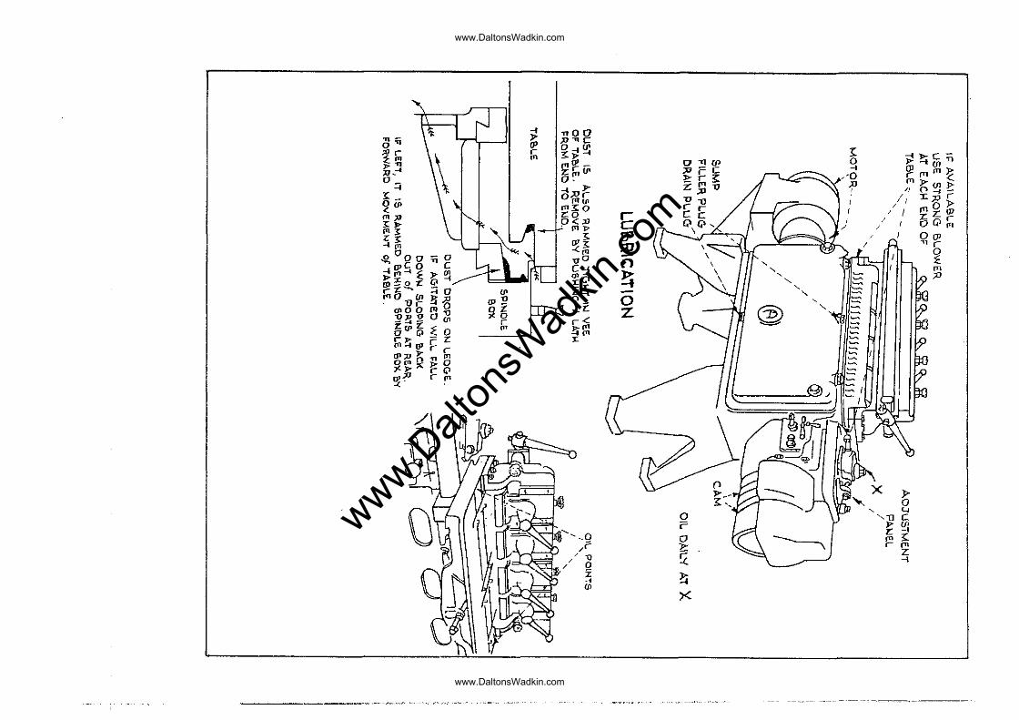
LUIlRICATTON
sump lubricated and provided the oil the groat8r part of the lubricRt·ion \.;i11
The level should be checked when the m8chine is not running. It is critic8l Rnd the level nmst not be aLlowed to drop 8.ny c_ppreciablC3 amount below the line markod. Over-f'"illing on the oth~r hand ",Til·l only rosult
11
www.Dalt
onsW
adkin
.com
www.DaltonsWadkin.com
www.DaltonsWadkin.com
in t;hc~ :3urplus cil being pumped by the cutter s;:dndlHs 'Vlhore they protrudG through the b:'ass cover plato. In· fact Gvidonce of slight oil 10akaga by this plato is R good indication that the amount of' oil in the sump is suffici~nt 2.nd Cf'.n be tPtken as a guide 8S to the correct amount in nddition to the level i.ndicC"1.tor.
Thl".: blend of oil t.o use is r.1obil Vactra Heavy Medium obtainElble from the Nobil Oil Co~, or from R~ S. Brookm2.n Ltd. If Qquiv~lent blends by other oil suppliers are used care tjl10uld be l;2.k~n to ~nsure th.?i.t it is to the same quftlity G.n.d type 0s the V; ..... ctrCl. heavy l'.lledium.
It will be found that when tha mAchine h8S run £or a period there is consider2.ble h32'.t generated in the sump_ This is quite in order being d~e to fluid friction resulting from thf:~ swirl of .the eil in ths sump and it is in no '-lay detrimental.
The ta.ble;mechanis~ points let into the work drops of oil each w~ek. excessiv() oiling. mu.st b(~
ia lubricated by the oil ~an at oil table surface. These roquire a "fow lvhilst some oil must be so introduc8d avoided.
Pumpi·ng"' 13.rgc qU8.ntitios of oil into the table mechanism wiJ.l not improv~:.: the functioning of' the mf1chine but it \~·il]_ lead to sawduEt ftccumul<'ltion. The need to keep the tRble mcch2nism clean is stressed in R sub~equent paragrapll.
Ti."!.8 control p~'":nGl ov("!r the;: gecir box should· also rBceivG the attentj.on of the oil CRn. One oiling po~nt,·markgd 'X' on the diagram is very im?6rtAnt and should rec6ive daily att.ention.
The Cf'lm tr<lcks c-.nd rollers ag?iin do not req·uire excessive lubric~tdon, ~s it ~nly lends to dust accumulAtion. The ·trAcks should be wiped cleAn from t~me to time and smcAred with ~ film of oil.
PneumRtic crr:mp m:.'\chincs· aTe fitted with i1. 1TSt.,artwDut I1
to remove ... ..r;:'tter, thet .should be dr~incd from time'" to time I
and Hn 11 Ayrlyne I! lubr"j.c"ntor which should be kept filled· "\ .. ri th Hn.ke·fiGld l:liagYl.?! S. P. oil.
The electric r!:otor hE".s two oiling points \"hich should receive w(;<.::kly c-,:ttontion. On machines for J pbn.se ;l...C. supplies, Cr2.btrc'~ auto stRr-deltEl st:::.rters c'u'c: fitted wt:dch should be filled to the line indieRted·~ith transformer oil.
CL"'".NING
The vi t2.1 po·int of chip ,~nd sawdus·t· CongrE',g8.tion is along the f~orit of the wotk tnble below Rnd behind ~he cutter spin(]le brass cov·or plA.te. This congrc-gation is hiddbn rrom normE,l vie"\\T and must thorofore be kept in mind. The diagrams show a scctionsl view of the m~CllinG And th.o points where
12
~ ~ TI fl
I
I] f\
www.Dalt
onsW
adkin
.com
www.DaltonsWadkin.com
www.DaltonsWadkin.com
the chips will congr0~~ttc. If allowed to accurnul~~tc they \-fill bo j.:rUSh8d solid by the: continU8: f'or"lnrd mO,,{,GmGnt of' 01.(: table and ovcntunlly 'obstruct. This may lmi -to strBining ()f' th8 tablE: mech[-,nisrn or h02VY '''oar in the cant tr2.cl(s.
To .. :voicl this nccumulntion the chips 'must be 2..gi t2.ted rroquDntly ~nd rogu~~rly so th~t they w~ll be d~slodeed and f8.l1 clown the sloping b2,ck of tho main frame: Hnd out of the t~rG~ ports E!t the renT. ~ strong blower should be used at aach ~nd of the Jnachine oyery week for this purpose.
If thE; :u;)chine cp~n be coupled to the dust oxhaust system in the factory it is of course much to be preferred.
GRINDER l'lTT;,,-CB1·'iI~NT &. CUTTER SH.!illPENING
Tho cutter grinding attachment is on thG rear of' the mp:chinc, F\djacent to tne motor end~ It is mounted on Ft
br2cket th8.t 0n2.bles it to be s\vung clG2r ' .... hen not in usc; in fact it must be swung cle2.r', othl~.rwis<.~ it w'iJ.l f"ou] thp-tabJ.0 when thz roed is e4gagod.
IYhGn in use tho 2ttr1chrnont is swung up and locked by the screw in ~ts bracket. It ~s driven by a cross belt from the pulley betWG0n the motor and machine. The cutter :is hold in thG hands, th8 arms being supportod in the machine work table. GraRter convenience for support CRn be obteined by cramping a piece er wood in the mAchine cramps.
Hhcn grinding the cutters care shc.uld 110 taken to folIo,., the origincll flu te f'OI'Hl ::50 .rC'~r c~~ i5 possible. Good quality dovot~iling will net result unless the cutters are keGn and Flr<:: cutting frc,::ly. If the dov;..;·tsiling is of' poor finish :;bviously th,::: cutt~Ks J'(;,quirc shnrp9ning but if Rf'tor shflrpan~ng the finish is re8~onAb18 but the shape is poor, it indic::tt(~s th2.t th:'J cutters are nc.t ground SO as tc? cut frocly. This is cutt~r ferm, as distinct f'rom kQc:::ness, th~t is ~t faul,t.
13
www.Dalt
onsW
adkin
.com
www.DaltonsWadkin.com
www.DaltonsWadkin.com
~I..PPENDIX I -' I H
HE-:lSSEHBLING jJj"CEINZS PACKED FOR EXPOnT
1':11.en p[~cI<\.,~d :for export it is usual to remove the Cramp Bridge and the C8m, to -facilitate snclosure in a smaller box. Th.<~ rGplHcing of thG ·C~\lll Drum has already been dGscribed ~ndGr "Equipping to suit "Style and Pitch " .
The Crc~mp Bridge; is sccured to the ta.ble by six screws J
"llu' (H) iu <::<:~cll of ·the bridge f'oe t. The dowels should bo knocked up, the "bridge bolted on Rod then the dowels tRpped down. In some: cas(-~s the vertical front cramp, oith8r the cccontric roller on the mnnu21 tYP8, or the yoke assembly in the pneumatic type, may Rlso have been removed from the bridge. The Gccontric roller should be replaced with the operating hRndlo ut the goar box end, i,c. 2.WQY from the motor end. The IJneuJikl tIc C1"d!JlP yoke shuuld be simil[~rly replPl.ced ·wi th the p12in side uppermost.
ThG :"1ir leads on paeulllatie type machines must Rlso bE replRced. These l"ads nre of' c;lif'f'"ront lengths, thG longer :feading -::.11.'3 front or vertic2,1 cri?unps, the shorter. the rear or horizontal cramps. By moving the foot pedals it will be f'ol. .... nd which pedal oper2tes which v21vc. The pedal rlC!c:rest th.:: centre of' the mnbine is to control the front vertical Crnlnps, henco the air outlet from the valva Fnaved by the iIlner pedal should be connected to the front cramps. SimilArly tha outer pedAl vnlve to the renr cramps. Note, by front vcrticRl cr?mps j.s meant those operating on to the fRee af the bridge; by r(~pr horizontal cramps. those operating on to the fRce of' thn tnblA.
On ~Rchin0s h8ving provision for ,"·ir drills th0 innormost vnlvc controls thCS0 drills, the double roller rocker boing :::!ctun·ted by tn'.) CAI!] AlonG. The air out.Lot f"rom this vnlvc~
shaulC: be connGctGd by the· third, . smaller diameter pipe provided, to tho drill feed manifold on the very top of the crp;mp briclge.
14
~
I www.Dalt
onsW
adkin
.com
www.DaltonsWadkin.com
www.DaltonsWadkin.com
;,PPENDIX 'B '
ST,.NDAHD R;l.j\fGE OF CUTTERS
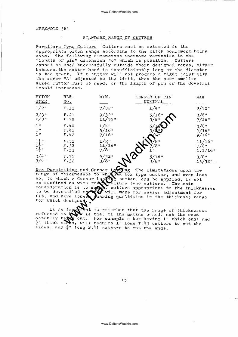
Furniture, Tvpe Cutters Cu~t8rs must be selectGd in the nppropriatc 9itch rHnge acc~rding to the pitch Gq~ipmont being ll50d. "The follcn"ing dimonsions indicntc vari0tion i.n the \'longth of pin" dimension "C ll which is possible. ·Cutters cannet bo used ~uCCGssfully· outside their designed range, either bc6uuscthe cutter hend is insufficiently long or the diAmeter is too gr",<'.t. If" cutter will not produoe a tight joint with the sciew "All adjusted to the limit, then the next sm211er sized cutter must be used, or the length of pin of the dovet2il ~tself incre~scd.
PITCH REF. MIN. LENGTH OF PIN MA..,{
S'TZE NO. NOHIN .. : .. I ...
1/2" F.ll 7/'32" 1/4" 9/32" 2/)" F.21 9/J2" 5/16" J/8" 2/'3 " Ii'. 22 II/J2" J/8" 7/16" 1" F.40 1/1~" 5/16" J/8" 1" F.ln 5/16" J/8" 7/16" 1" ~'. 42 7/]6" 1/2" 9/16" 1 J_" F.51 1/2" 5/8" 11/16" li" F.52 1l/16" 7/8" 7/8" l i " F.5J 7/8" 1" 1.1/16" 2
3/4 " F.J1 9/32" 5/16" )/8" 3/4 " F.J2 '3/8" 3/8" 15/32"
Bcx Dovet8.iling nnc1 Corner Locking ThQ limitAtions upon the rp,ngo of thicknesses to which? box type cutter, and evon less SO~ to which ~ Cornor Locking cutter, can bo applied, is not so confined as with the Furniture type cutters. The r.1(lin consideration is to select cutters appropri8te to the thicknesses to be dovotailod ~s they will mGke for easier adjustment for fi t, nnd hr:ve l:Jnger w,)aring qUfl.l ti ties in the thickness rango for lihich desiL~n0d.
It is importgnt to r0m~!~bor th2t the rl1uge of thicknesses rofarred to bGlow is that cf the mnting bG8~d. not the wood nctuc":lly being cut. For example f! box h8.ving I" thick ends p,nd ~II thick sides, will roquire It! long T.4J cutters to out the sides, C':.nd ~~"" l'")ng P.I.!"l cutters to CJ.lt the ends.
15
www.Dalt
onsW
adkin
.com
www.DaltonsWadkin.com
www.DaltonsWadkin.com

FITCH T..[:lPEH -aox F ... ..R ... ·l.LL:2L C/LOCiC THICIUI/:~SS OF 1 ... ,,i·LTING SIZE REF. NO. BOX R.~F~ NO. REF. NO. HIN N CJ.iIN,L BO,~D
~L\JC
1/2 11 T.ll P.ll C .. ll 1/4" J/8" J/8" 1/2" T.12 P.12 C.12 :3/8 " 1/2" 1/2"
1" T .1'1 P. '~·l C.IH 1/2 11 J/4" J/I+" 1" T.42 P.42 C.42 5/8" 1" 1" 1" T.4J P.!;J c.43 7/::;''' li ll l..1.u
4
l}l! T. SI P.Sl C.Sl J/II" lttr l-j-I!
3/4 11 T,Jl P. Jl· C.Jl J/8" J/.+" J/4"
-i.,
16
www.Dalt
onsW
adkin
.com
www.DaltonsWadkin.com
www.DaltonsWadkin.com
"Q--f
0'" ". ,,00
~~ rP ","QC
,." :;; ~~~
»,-'
0" z:",'"
0-"'" :r
o· ;rIre
0 ~~c:r;
3:_ -f p'" ~.-;::
-f (JJ Ul
2'" Z:~1J
/0 ,mill):>;
0",'-~
rn". <::
rn", "':t'" ""0
" ... zoO r
.- r
/// n ~ ~
"':; P~;g
Cc I 1/ J:;or
Z::; C G\Q ....
I /, J1l~~
... ", .,,>: IP
I / I Z:QI
0
/
~ 00-0 -:>: ;0
o '"
-IcpS O T1 C '"
D(JJ
,,0 -~~ ~)?" ~
c ... n -n.-
~z:.e..z: ~ <P- !i
~
(tlO {p~,g ,,0
(f' -J:
In
U r " ","9 z ...
;D
-:S0O(JI~ n o- D _~!!ocn
... c:. Z ,
z: fP z: r r< @ o Q ~ 0 on
""-
~~(JJ~z !i~
~
J:
~ ~
~iQ ~ § ~
~ ~ ~ -
~. l (fI
~ ~ ~
~
:::::/ I
,.. 0
0 , '-'
"1l C , ;=
, ,0 /f'
Cl
". '!l -eo
1:
/-0
rn "{.
/ 0 !(
r rn
Z
Z
-f ~
....
IP X
----_ .. " ....... ..
www.Dalt
onsW
adkin
.com
www.DaltonsWadkin.com
www.DaltonsWadkin.com
WUIJJ
. ->
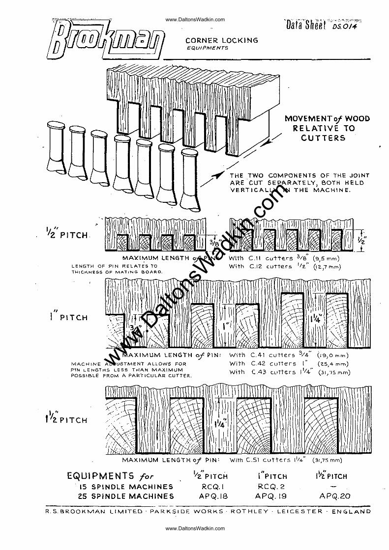
CORNER LOCKING EQUJPM£NTS
~ -;/
'Oil tfS h ee fDS.~OI:;'
MOVEMENTof WOOD RELATIVE TO
CUTTERS
/ /~ THE TWO COMPONENTS OF THE JOINT
ARE CUT SEPARATELY, BOTH HELD VERTICALLY IN THE MACHINE .
I 11
/2 PITCH
"
MAXt";llUM LENGTH <if PIN: LENGTH OF PIN RELATES TO il-lLCKNES5 OF MATING BOARD.
"
I PI TCH ,
MAXIMUM LENGTH of PIN:
MACHINE ADJuSTMENT ALLOWS FOR PIN LENGTHS LESS THAN MAXIMUM POSSIBLE FRoM A PAR"TICULAR CUTTER.
I " I'ZPITCH
MAXIMUM LENGTH Of PIN:
EQUI PMENTS for I/i' PITCH
15 SPINDLE MACHINES RCQ.I 2.5 SPINDLE MACHINES APQ.IB
With C.II cutte.rs '/8 (9,5 mm) With C.12 cu'trers 1/2." (12.,7 n-,m)
With
With
With
C.4-1 cutter5 3/4 "
C.42 cutters I (.43 cL.Ttees 11/4"
With C.SI cutters Ill .. "
" I PITCH
RCQ.2 APQ.19
(19,Omoo)
(25,4 mm)
(31,15 mm)
(31,75 mm)
I vi PITCH
APQ.20
R.S.BROOKMAN LIMITED· PARKSIDE WORKS· ROTHLEY LEICESTER· ENGLAND
www.Dalt
onsW
adkin
.com
www.DaltonsWadkin.com
www.DaltonsWadkin.com
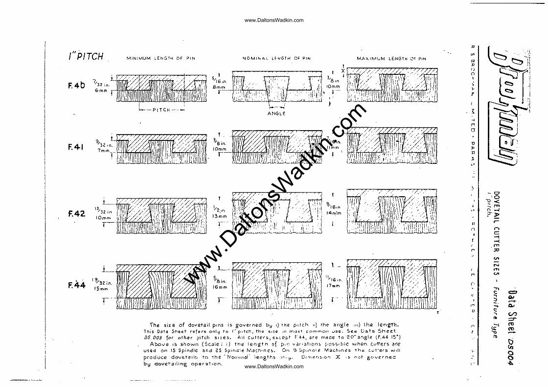
f" PITCH MINIMUM LENGTH OF PIN
F.4b
I ~-- PI TCH _ ..
9 L "32 In.
5 I "'16,(1. Bmm
l----
NOMINA.L LENGTH O!: PIN MAx.IMl.;M LENGTH 0~ PIN
ANGLE
F.4·1 7 m m ,nHlirmrrnfT1'i-li
3/Bin.
IOrnrn r'---
t. ~IGjn Ilmm
~ '/ .
F.42. 13/32 in
IOm." T~
L __
F.44 J 9/32 in. ISmm
I'
I "'2.,n 13mm
t_ ,,' /
L._ :1 \
11 ~8;n. ' . ' \'1
~ "rG In
\6mm J7!'IQm
;;' I.:~ \1 t r .
The size of dovetail pinS is governed b':i I) the pitch 11) the angle Ill) thQ len2th. This Datll Shee.t refers on[';I to I" p,tch, th" s,t.e ,n mo!';T cnmmOIl uSIL See D2Ita Sheet. DS.003 for other pitch sizes. All cutTers,e.~c.ep F44, are (n21oe to 20" angle: (F.44 Isa)
Above IS> shown (Sc.alei i) tne iengtn of pin va!'3tlOn~ ~OSSlbie whgn (utters ore uS(ld on 15 Spindle and 25 Spindle Machine£>. On 9 :Jp,nole Mac.hH'H?5 the c.u1ters will produce dove.tails to the "NolllllI~I' len8th~ .HI'~. Dlmp.n~lon X .s noT governed by dovetailing operatIon,
.... /, /i //.-//. , ~' ,
..-
, j'
.D
'" '" :c f)
Cl
'. " T
l: ., '" [J
u
" 11
~ <"
n ()
r
'"
'" o
'"
"
"
~! , ·~i'i ~" , ~'
r c:::, -:
~ :1
'§f I
(2' ~-1
-0 '0
'2< -." "-I ?"l>
r-r> c:: -i -< ."
"" '" N rn <I>
." <: = .,
AJ ::J ~ ~-.... a. <: -. er.> .. =:r
~ "" "" .., ~
'" ~ () () ~
www.Dalt
onsW
adkin
.com
www.DaltonsWadkin.com
www.DaltonsWadkin.com
JJj~l[JilJjj]7 Data Sheet DSOCG
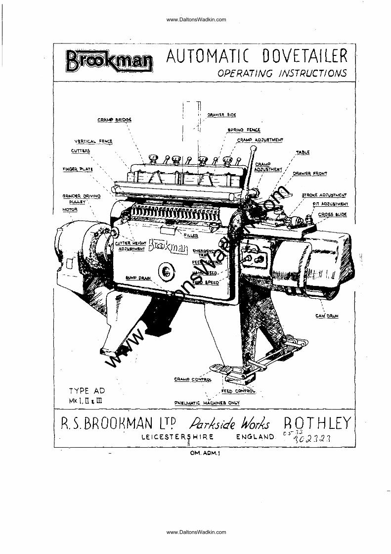
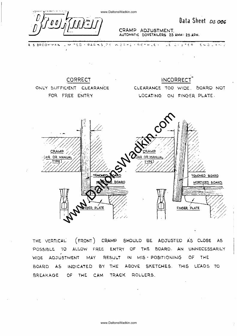
CRAMP ADJUSTMENT. AUTOMATIC DOVETAIl-ERS. 25 AMM: 25 APM.
R S a~cclo(·""Ar... ""'" ... ~::. CM.~"'\5 "" ... ,;.. hC~ .... ~E.' _~ :;: ... ~Q s .... ..., ~ ..
CORRECT ONL,( 5UFFICIENT CLEARANCE
FOR FREE ENTR,{
['" , If '.
//// ///' . ~, //
"71
. . '/' / //,,/
CRAMP / /' ///, . (AIR OR MANUAL
',//NP~)/ ;///"7/ /.
//
FINCl'ER PLATE
// /->
lNCORRECT~
CLEARAJ..lCE TOO WIDE. oOARD NOT
LOCATING O)..J FINGER PLATE.
/ / ' /
, / -- .. " --CRAMP --.
. (AIR OR MANUAL, / T'{P') / ",// /
///X/%/,/ /'i //,,/ //. / / / /.
Ti:NON~O SOARO
MORTICEO ~OARO,
~."//
~INGE~ 2:~; ,/ . / /
/ /- // .'
THE VERTICAL ( FRONT) CRAMP 6HOULD BE. ADJUSTED AS CLOSE AS
P05515LE. 10 ALLOW FRE.E E.NTR,'i OF THE BOARD. AN UNNECE.SSARIL'i
WIDE ADJUSTMENT MA'i RESULT IN MIS' P051TIONI1-J6 OF THE
BOARD AS INDICATED B'i THE ABOVE SKETCHES. THIS LE"ADS TO
BREAKAGE OF THE CAM TRACK ROLLERS.
www.Dalt
onsW
adkin
.com
www.DaltonsWadkin.com
www.DaltonsWadkin.com
''''.~_'"'-'' " ... ~.,-,'<-.. '-';""~')_'" '·'"<."-~',,c ".'
jjl!.!JlfJiEJl4/ Data Sneet DS007
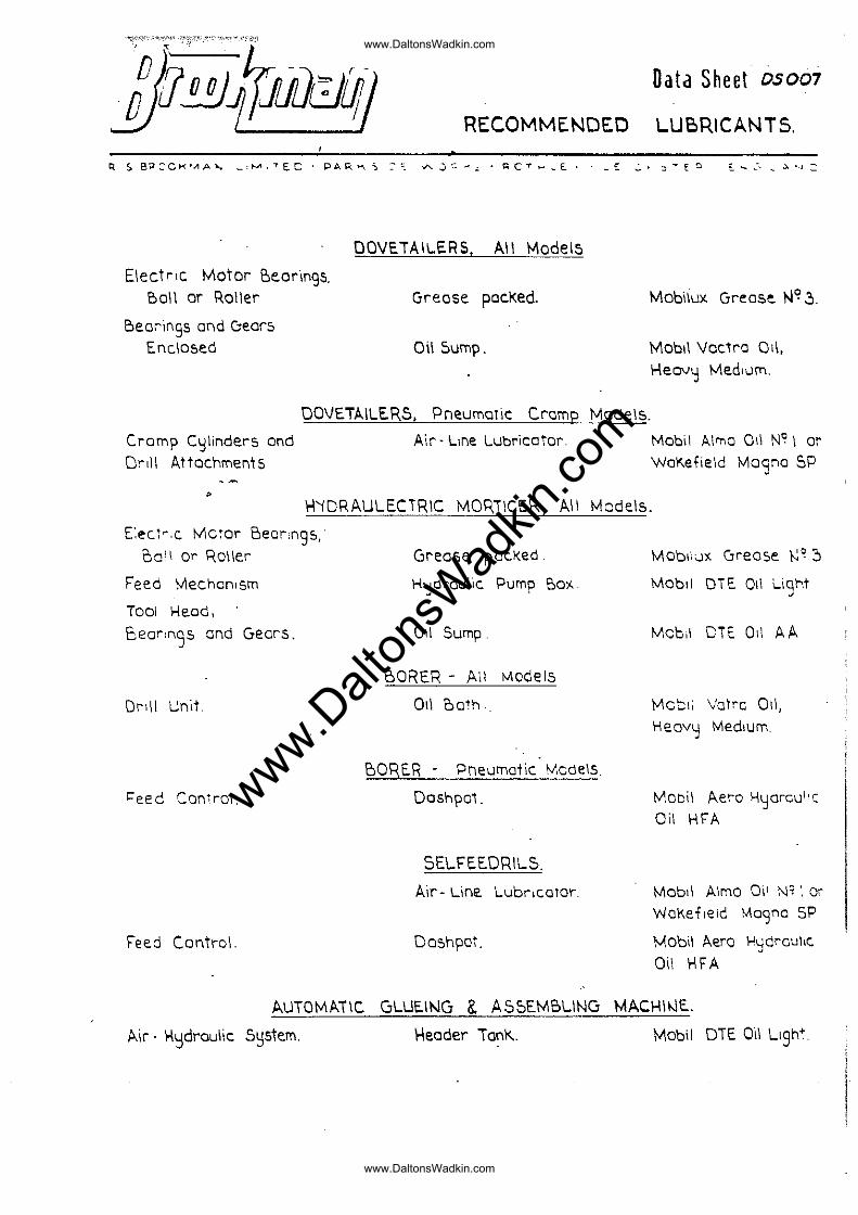
RECOMMENDED LUBRICANTS.
R 50 B?:::- CH·..., A)o.., _ """,'" E. C . PAR >-\ ~ ::. ""'-:) '.: .:.' ~ C ,. ... ~ £.. _ £: ..:.' ::I .... £ 0 £. ..... ,:- _ .),. "-j
ElectriC Motor 'Oeorings. Boil or Roller
Bearin9S and C:1ear5 Enclosed
OOVETAllERS, All \oo'\odel5
Grease pacKed.
0\\ Sump.
Mabilu)( Grease NC!~.
Mobll \Joc1ra Oil,
Heovy Medium.
OOVETAILERS, PneumaTic Cramp Models.
Cramp Cylinders and Drill Attachments
,
Air· line lubricator Mobil Almo Oil N° I or WaKefield Magna SP
14'iDRAUlECTRIC MOP,ilCER , All Models.
E:ecl".c Moror Bear,ngs, 00'1 or ROI!er
Feed Mechan,sm
TOOl Head,
cear,nqs and Gears. -Drd I unit
Feed Control.
Feed Control.
Grease paCKed.
H'::I0raulic Pump Ba",
Oil Sump.
BORER - All Models
Oil oa'h
'OORER - Pneumatic ModelS.
Dashpa1.
5ElFEWRllS.
Air- Line Lubricator.
DOShpOI.
Moblic.JX (jreose ~~:)
Mobll DTE Oil \...iont .;
Mob,1 DTt. Oil A A
Mobli Votre all, \--Ieovy Medium.
MObi! Aera Hydrcul'c Oil \-IrA
Mobll Almo 0'1' N"·. Or WaKefleld Ma'3na SP
Mobil Aero Hydraulic.
Oil HFA
AUTOMATIC GLUE.ING & ASSEMBLING MACHII\lL
Air - H~droulic s~stem. \1eader Tan\<.. Mobil DTE Oil ll9ht
www.Dalt
onsW
adkin
.com
www.DaltonsWadkin.com
www.DaltonsWadkin.com
Data Sheet DS 010
SPINDLE ~EPLAC:EME.Ni OCNV.l "'\\..E\\S .
R. S:BROOKMA~ LI,.....\TE.D· PAR .... S.OE \/\iaRk.S· J;OT).4'.\..£'Y • L.£"lCESTE.R . EHG LANO
r- - , I .'
:~, . ,
\
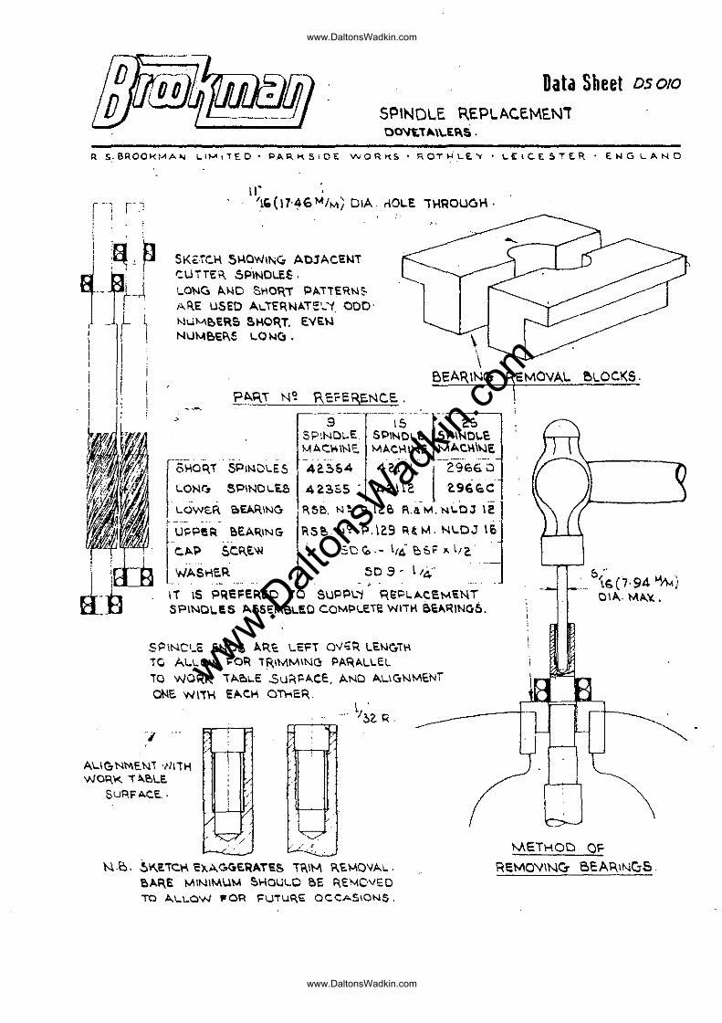
II' . 'I' (11'~6 ""it,." DIA rlOI..E 1I-lROLlC,H.
SK"rc.H Si-IQWIN'" AOJACEWT t:UTTt:K. SPINDLES. '_ONC> "-"'0 SI10?,T PATTERNS A~E USED ALTERNAT\:'_'t. ODD' Nulvle,ER& !!>HOR,T. E"E~ NUMe.E"S 1..01-lCl. \
\
!:A.I=\T N~ ReFERENC.e..
BEAR,ING lEMOVAL ~LOC.KS.
> I SP~:~~E '~PI~t~l:- ~~I;~\'C
LON~ SPINDLES 4~~5S' 4201\2 a96~C . _. . ~ , --LOWe. ... e.EARINC, !>'~B. N ~ P. la€> A.a M. NLOJ If
rU~p!" e.EAI\ING l'\5e,N~ 1'.\29 RO.\. NI.DJ le
C,I>.? ~C"E'N SO ~ . - 1'4 '0;; F .~ l/c.
WASl-laR so S - 1/4" . -
IT IS P~EFE~EO TO SUPPI.'j qEPLAC.EMENT SPINOI..e.S J>.SSEM6I..1i:O COMI>LETe WITH eaAI'lINGS.
SPINCU; ~t--\os AR.~ I.EH QV;;\( LEN",;" Te AI.\.OW I'OR TRIMMING PARALLEL TO WO~K TAi!I\.E $u~!oACe., AND A\"I(jNMeNT
ooe. WITH E/'.C.H On..ER
1
A\"It:;.NMENi 'liITH WOR'o<. ,. A.I!.LE.
SuI'\FACE ..
~,
l . I~? R .
...
N.b. ~I\EiC\'\ El<.Ac.GERATl'S T?,IIJ. ?'''MOVA\.. BAp,E MINIMUM ~HOULO BE ~E"IovED
TO A\"LOW .. o~ \=UTup,e: OCCASIONS.
o " _ '\&(7·94~)
OIA. MA¥'.
METHOD OF
REMO'lINCr B1:A>\INGS.
www.Dalt
onsW
adkin
.com
www.DaltonsWadkin.com
www.DaltonsWadkin.com
~~\\ ~~~ 1---
.::...:~
-~=\
~o -Iz n", ~
o --e-I~~ -0
.-0-~~ o
1-----1 -t-- '1--::;...1----=11- . -- . -AO- . -- .
--0-.
--9-··0 -0 -0.
-0-· --9-.
KM\!-==
. _-----_. ~~~~ --.---~.--~§tt
~ - tf1.'!:-D=::3
z ._ m
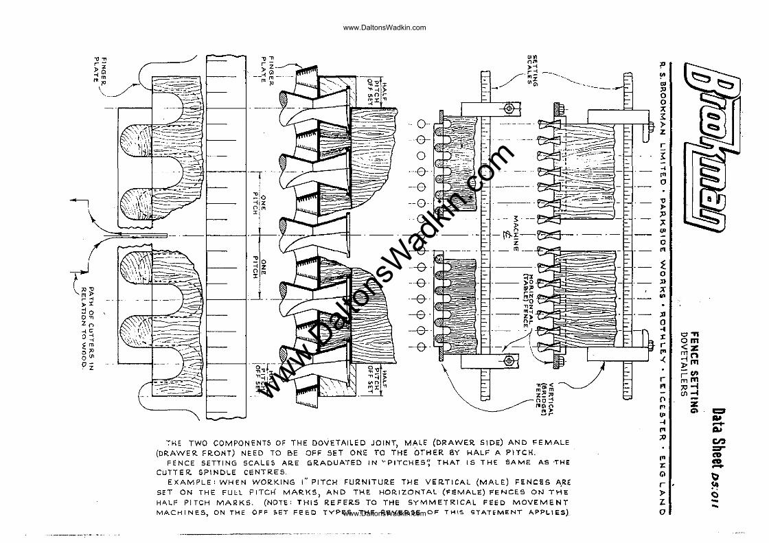
THE TWO COMPONENTS OF THE DOVETAILED JOINT, MALE (DRAW.ER SIDE) AND FEMALE (DRAWER FRONT) NEED TO BE OFF SET ONE TO THE OTHER BY HALF A PITCH.
FENCE SETTING SCALES AR.E GRADUATED IN "PITCHES': THAT IS THE SAME AS 'THE CUTTER. SPINDLE CENTRES.
EXAMPLE: WHEN WOR.KING I" PITCH FURNITURE THE VER.TICAL (MALE) FENCES A.RE SET ON THE FULL PITCH MAR.KS, AND THE HORIZONTAL (FEMALE) FENCES ON THE HALF PITCH MARKS. (NOTE: THIS REFER.S TO THE SYMMETRICAL FEED MOVEMENT MACHINES, ON THE OFF SET FEED TYPES THE ReVERSE OF THIS STATEMENT APPLIES)
.. -----.-.---
P !"
'" " 0 0 ;c: 1: ,. z r
I ... "' 0
" ,. " ;t
'" 0
'" i 0
" X .. ;lI 0 ... :c "'." om r <z: "' mn -< -im
l> -en
r r;;m PI ;10-1
UI-I n z f'1 U>
c:> c::r ... -I ..... f'1 AI
" en :::r ... CD CD z: .-
Gl ~ r \It .. ,.
C) "L ... ... 0
www.Dalt
onsW
adkin
.com
www.DaltonsWadkin.com
www.DaltonsWadkin.com
"Dafa'"SH'eel-; DSO/6!
SUMP l..UBRICAiION. AUTOMATIC DOVEiAIl.e.R,6. 25 AMM. 2.5 APM.
TOl' COV!" I'l ATE
UPI'(" IIE"""IN6 aLOCK
OIL TR""P
SPINDLE FR""ME MAIN GEAR
.. >
6AUGE GlIU3'
OIL
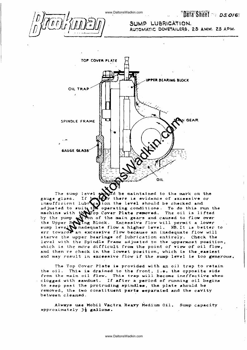
The sump level should be m&int~ined to the mark on the gauge !"laf's~ If howa-ver there ia evidence of .xc •• sive or lnsufficient lubrication the level should be checked and AdjU8t~d to .uit the operating conditionD. To do this run the machine vith the Top Cover Plate raDOved. The oil is lirted by the pump action of the mAin gears and caused to flow over the Upper Beari~ Block. Excessive flow will pe~it a lower ~ump level, inadequate flow a higher lQvel. NB. It ~s better to err towards an exces8ive flaw becauee an inadequ.te flow will starve the upper bearings of lubrication entirely. Check the level with the Spindle Fr~ adju8ted to the uppermcet poaition, which is the mo're dirficult fro .. the point of Ti"", 0(' oil flow, and then re check in the lowe.t p08ition, ~hich is the.eAsie8t and may re~ult in excessive flo~ iT the sump level ie too genero~.
The Top Cover Plate i. provided with an oil trap to retain the oil. Thi. i. drained to the front, 1.8. the opposite 8ide from the main oil rlow. This trap will become inefrective when clogged w1th sawdust. If arter a period of running oil begins to oeep pa~t the protruding spindles, the plate should be removed, th~- two constituent part. eepa.rated and the cavity between cleaned.
Always USe Mobil Vactra HeayY Medium Oil. approximately Jt 8a~lon..
Sump capacity
www.Dalt
onsW
adkin
.com
www.DaltonsWadkin.com
www.DaltonsWadkin.com
"'''-'-'-''''~-'
I1t\M \ IMf
lilll!
, ,
rA-l
/,/". .. , ,
, ' , , ,',
~ ~ -~ , ' " ... --- .... ....... - ..... '"
\' , , , , , ~_/ ,/ ,;::--, , " , " " , , , '
'~::-:.>" , , ", , , , ' ..,"/' <:--;
" , , I, , , , , .... -- ...... ....... - ... " , ,
"
~--
f---- -
, . B f--
~D·;i<¥'»Jf.S'I!·'·Wm" ~ ! ~! lifa'" u'lfe hr!"']:)'S1~O:Z2;~
. ~-.:~~
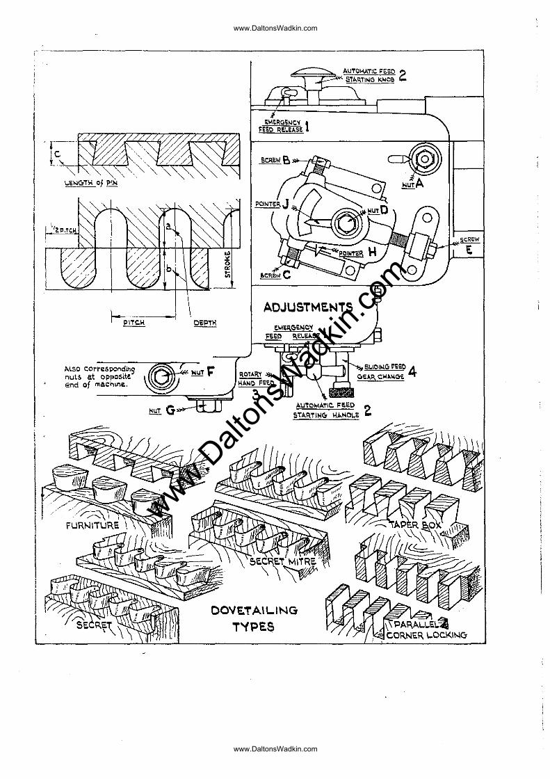
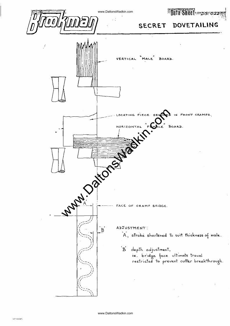
SECRE.T DOVETAIUNG
" " VER,i'C.A.L MALE. BOAR:!).
I _ LOCATING p\EC.E. SEc..UR'E.:I> lW FP-ONT CRAMPS.,
11 " HOf!..\ZQNTAL FEMALE. SOAR.:D.
FAC.E.. OF CRAMP SRiDGE..
AlIJ'USTMENT:
A, stroke shortened to SV-It thickness of mo.i,,-,
'-B depth. adjustment, je_ bc-,cl,ge. to-"-" vlt-;",o.te tro.v,,1 restrict",;, to pr"-v"-nt cutt",r br"akthcov~h_
,
www.Dalt
onsW
adkin
.com
www.DaltonsWadkin.com
www.DaltonsWadkin.com
/f/u@Ifpwmff) L .
SEC7,ET DCV· .T •.. E ING
R. S. BROOKMAN LIMITED PARKSIDE WORKS - ROTHLEY - l8CESTER
ENGLAND
Data Sheet DS.02J
Secret Dovetc.iling is cut ueil:g t;'~e standard furniture equipment, the required adjustoents coning from phe setting controls incor~orated in the Dovetailers.
\'hen cutting the norClal Furniture dovetail tr.e two cor.::ponents, ::1a1e and i'e!:'.2.1(? t are cut togetl:er. T"i.-:e ''''or1-: Tnble movement, in re12tion to t~~ cuttaTe, is such that t~e cutters pass through the vert~cal b02rd, to forn the illRle pins, and then cut into the ~orizant81 b0ard to forD the f'emRle sockets~ VhGn cutting Secret doveta.ils th£ 1r!hole of' the cutting r:-.oveocnt is C j!1i'ined to each co~~.:...:.cnent of the joint, l·,hicr.. being so they hfive to ba cut ~ositicne~ siee by side, in the cra~ps, or cut at ssparate 0pereticna if tLe wQr~ing ~idth of the ~achine so ri:.:quircs.
Tl!.8~ &etting uf. procedure: is for the vertice.l ::;alG beard to be plc\c~c~ in tr:s v8rtic2:1 CT?r:,pS, and the adjust:n0-nt se set that the cutter, at the crest of the round, just undercuts into the outer :fnce of the: bG2rC~ in ths ncr:nal fnshion. On Lever opernted :::1F..cr .. ines this is ctcLiGve0 by :;.csiti0!ling the f'or'.!;.'<"~r ?lE\tc; en ~uto3atic ~2c~in~5 by setting tha "DeFtl~" adjustmGnt. TI:~ fcrward traverse cf t~e t2bla 2USt nGW be restricted so as to' prevsnt the cuttars frL~ break~ng t~rou~~ t!'~e ttickness of the beard. Tec~nically, at its fcr8~iost ~osition, t~e fnce of the cranp bridge :;~ust !lct l:;~\SS bt-yond th0 scribe pariphery (;:f the dovet.?:il cutt02rs. Tr~GsG .:djuet:r:!ents ::··:ClQ6 tr_s ;,--;'2 x i:l.U:-:'i d,)V;~t2,il
forr~"! will b,"-, obt.:--,in0c:' \>.cc.::..r(~in!~; to the thic].~neS5 ~.f vertical ~21e bG~r~ to be worl:ed. .
Ne: furtl'l-.:r ;:.::nc;::.inG setti~g, 8XC0;:t ;.-·ar-::...r·~·s by tightness of fi t J is reql1irsG t:.· cut t~:;.:: hcrizcntnl :f0n2l~ bee-re, but 2-
.~Grward 10C2ti:'n rOT t~is bC2rd will be T2quiree. T_.is is t~e mcr6 ensily aci~i2v~d by ~3r[lCnently s0curing the vGrtic21 crn~~s, 8 pi.eC0 or weod rebato,~ to tl:~ cxt.nt tb~t t~l8 end of th~ hGrizont~l b:·21~( s~2ul{ ;r~jGct b2yon~ t~3 bri~gE face. ( G ' ,,~+- ",-,,~t DS 022') S . e _-'<:, ~ <. ...J.L _<_.:; • •
F~t adjust~&nt will ~~~ly in tt .... nor~~~l w~y.
SUI::!:I[.:.ry:
TI-.c ssttir'!gs c.re: L,;:;v;~r Cp~.y;-. tee: En.c>incs:
.,) T~ - . ."- c' t; tl'·o l~,··r--·~· . l' t·,· t~ .... ·- .. Tn:';)l'-~ '.> <.-~ _v , ... ;:>1 _vn ~,-. ~ .... -;:::r ~) <.-1 \;;l J.n 1~x;" nt .. r ... c-_ ,.l.·;nnbr
:cccrdin~ t;~ t~c t:~ickness sf vertic~l b0nr~ tG be W("rk0d.
b) To licit the f~rward ~0V0~snt l.f tts w0rk t~ble by S[!ttintS: t~':'G c1er:;th screw se. ~ns t·::· pr0vont tbe cutters brr.:nking thr::;ufh th~.:: triickness \. f' tLu wO":""d.
--~--....... ~.- .. -.... -.... -.--.. -~~~~~~~~'" ....... -... ~, ........ .,,~,~~~-~~
www.Dalt
onsW
adkin
.com
www.DaltonsWadkin.com
www.DaltonsWadkin.com
J\utc.D::tic r'!r,cLirh)s:
D".ta Sl-.80t DS.023 cuntinuod
0.) The stroke is 51." rt;-~nnd t(· tL_ ,:,;;,-,unt deGI?:e<1 suitnblG Jer the tl"icknc'ss , .. 1 vDrtic(':l b· , .... rt-! t. bo wc:rkv~
b) Tll ':> -lo,,··t'," -.--lJ·uot,·· ,-t ·""l'ot'r;.::: ""'V-_~l ·'cr,·ss t· t"~ \;;! (.l_!,' ! C;"i .-" ,;.: j ".'." ~ '.' _~ .'~ '...;'.' <. ._ ~ " .. ,,;; pc,siti ,n tlSocr'<:~t" "-)t1 t:·.:.; sc::l~., t-_~ :)r0v·.;nt cutter brer'J.: tl~r:_.u[(:.
In 0.11 C[':SGS it is ~dvis,"lble t~ cut tri .. ~l j:.;.int t,} dot_.r:r!ine thE: fi t n.djust:~c:nt i"1f't....;r tL(; strok0 C1(:justn;,~nt n.n(i 'p0si ti~jninG have b0~n s~.t s~tisr~ct.~rily.
www.Dalt
onsW
adkin
.com
www.DaltonsWadkin.com
www.DaltonsWadkin.com
/~u(j]J01w§ffJ ,-.-- - 'j
Data Sheet DS.r.25 Page 1
tJC. ~L T.~2J ,~~ F~~?::: MECr-=;i1.r-!ISM Al1tO!TIntic ~ovr:;ltflilGrs 25.J:..~>-l'-': & 25 • .A~:M
He:foT~nccs: Dr2WiG~s 72133, 721Jll; DClt:". Sheet 013 Instruction ji~nuRl.
Work Table Move~ent
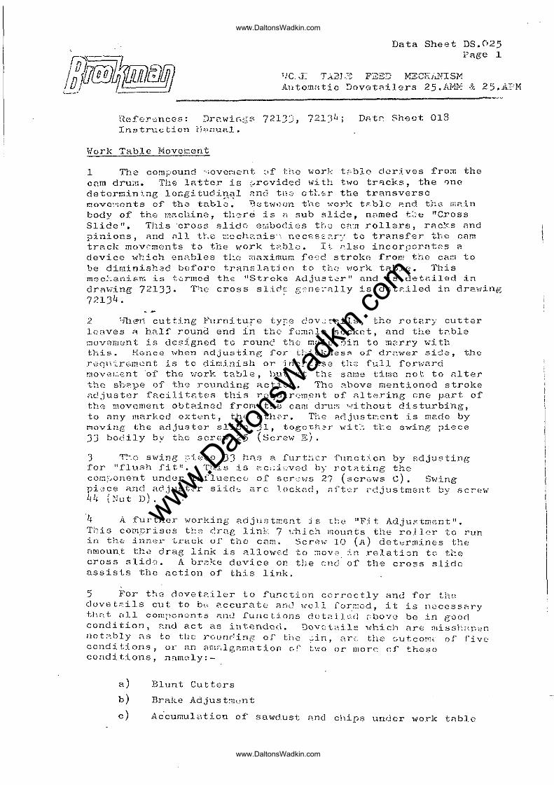
1 The comi_,ound -·'overlent :If th.c ,\liork t;,·blo derives f'ro:T. the C2.m drum. Thf) latter is ;>rovided \vi th t,,,o tr:=tck.s, the Qnc detormin~ng locgitudi~~l ~nci tli2 atLsr the transverse J':'!ove~';cnts of' th0 table. tJ(;to;·/oen the '.\'orlc tF,blc ?:nd t;:G r;,Rin body of the mAchino r tl1erci is n sub slide, n~med tbe "Cross Slice ". This ·crOG!:'; slid::-: er.ibodios tr,Q C;;::1 rol18rs f rRc~{".s Rnd pinions, Rnd nIl t~e ~CCh23is" necesz~r-: to transfer the cam traclc mOV0ments to the work t2bla. It ~lso incorporAtBs a device ' ..... r:ich GD<'!.bles ti:.c ;'naximur,; f'c-;.:c. strokc~ IrOn! the car:1 to be diminished beforo trHnslRtiefl to tbe \"Jork tA.ble. This m0c~:an~srn is termed the I'Stroke Adjust0r 't nnd ~s detfl~led ~n
drAwing 72133. T1C cross slidE g(n&~~lly is dGt2~led in dr2wing 72134.
2 '"jl:l~11 cutti::"lg Furniture ty[.e c:ov,~':C':ils, the rotar:/ cutter leaves ~ half round end {n the i{l~~18 socket, and the t~ble movemont is designed to roune the mele ~in to marry with this ~ HGncG when ,.,..dju~jting lor t~::icknes~ of' dr.;;.wer sidG, the r\::('p~:;"rbm0nt is to dir.~irli5h or inc!"::-:c:.s8 the f1.:<.ll Iorwe.rd rnove~€nt 'of the work table, tlUt ~t th~ same tirnc not to Alter the s1;.°213e of' thr~ rounding action. ThG ~bove mentioned stroke ndjuster facilit~tes tllis rcquir0m~rlt or nltering cnG part of tt!G ~ovemGnt obtRinGd from the cani dru;~ without disturbing, to any marked ext<:~n t, thQ 0 th.;:-·r ~ TI-~e A("1 jus tr.-~'.0n t is nla.do by ~ov~rlg the adjuster slid() 31, tOgCth2T w~t~ t~e sw~ng ;)~0Ce
JJ bodily by the screw 25 (Screw E).
3 T~-_o s"\\rine ;::i0C9 JJ t:ns a .furt~i{":r i'ur..ction by El.djuBting for "flush :fit!!. Tbi5 is ~::c!;i:,:·V0d. by rot<=lting the cc~~onent under influe~c0 of scr~~ws 27 (scri~ws C). Swing pi\-:!ce and ao,just'~"r slid'.:; arc lockGd, n.ftt::r .~d,justmGr:.t by SCT'€~\v 44 ,Nut D).
'4 A further working 8dju.'; to::Gnt is tLe IIFi t Adju~tmGnt ". T~:.iG cotTl.~rist)s tt~·:,~ c::cag lin.l,·. 7 ,-.-hich mounts the roJ 10r to run in th~ iIlner traclt or tho C8m. Screw 10 (A) det~rmines the nmoun.t tl!.0 drag link is nllowGc to ~ov.:.~. j_!1 relatiGn tG tl"!0 cross slid·::~ A brc:-ke device or. the cnc: 01 th~ cross slide assists the action or this link.
5 For t~e dovet~ilGr to function correctly and £or th(~ dovet~ils cut to b0 ~ccurate And well ror~!od, it is t10CCssRry ·thnt nll cO!l!;~cnc:nts i'<.l1d ['UIlC tions d()tail~~~d ,:boVG be j_n good condi tiOD, ~nd act as intendcr\ ~ Dov·:::tnil~ ..,.,'hicJ1 are :uissi;,q),::n nct?_bly ;'ts to UlD r(ivnr!in@ of' the -:--ir., <:'"Ir~: the (~utco!"r.;_ of' Five' condi tions, ur an 8r;~.:-,lgalP.ation (J' t,;~o or morr. C:J thes0 conditions, n~m8ly:-
a) Blunt Cutters
b) Brilke Adjust:nent
c) Ac-cumul~~tion of sawd.ust fl.nd chips under ''lork tnblo
www.Dalt
onsW
adkin
.com
www.DaltonsWadkin.com
www.DaltonsWadkin.com
Data Sllcot DS.025 P~e 2
d) Cross Slide- and t~b10 slide, including rack meci\hnis~, require oil~ng and Adjusting
e) ~renr or misadjustmcnt of the table motion nlech~nism
There' is a sixth C?S0 whe'l t~_(~ b~:ll r~CR 23 used ?S a rol10T ~:ns broken.
Blunt Cutters a)
6 Cutters \Iltl~CC rsquirc shf\..rper.:ir..g or l':<-:.ve not ,been ground to give 8,.uffici0ntly free cutting ?ction, arc 2. prime CRuse of indirferent dov0t~iling r~sults. It is im~ortnnt to ensur8 that the cutters arc s1-~arp, anc. tl!;:,t the rake r!.C!s boen adjusted to ft.l.';~ ty~)8 of ti~;lber being r;:p.c::ined. Blun.t cutt,aI's S(~t up u.chatt,erll on both the table !7!Q'Vc:-:;c:ut and of .th€' cuttGr sr·ia.:Il{.;;s th:')-!,J3~'lvcs, n~r: indiff:'rent l:u;;'lity result's.
Br2.k.e Adjustment b)
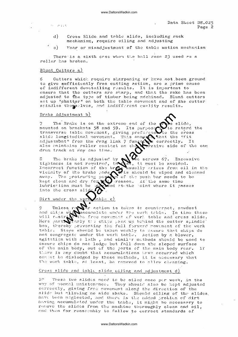
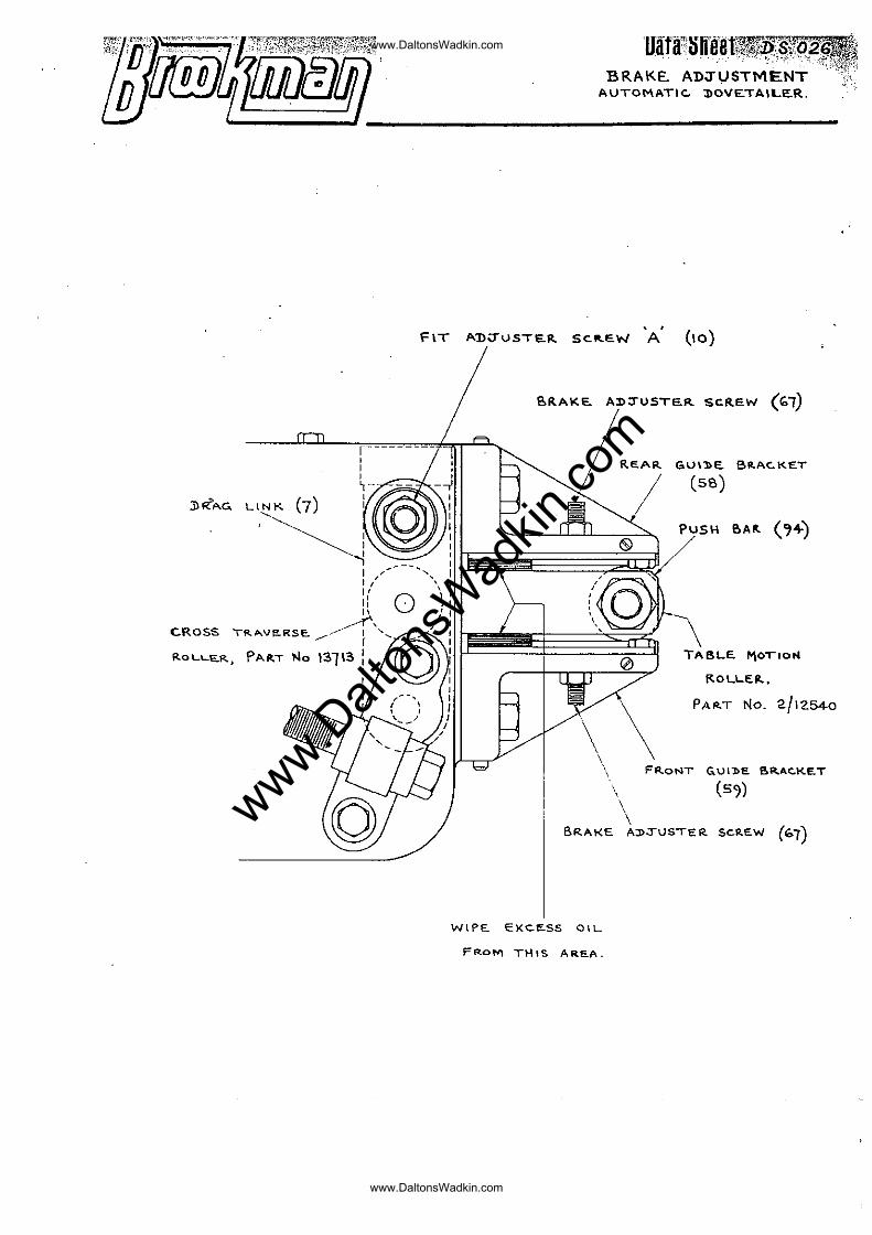
7 The :Brfl~':C: is on tlH::· cxtre~:lC end of the cross slide 1
nlcuntsd on brackGts 58 and 59. Its purj)osc i~ to rGt~rd the trnnsveTs0 tablE) ]7~ovu~cnt, giving pref\~~-0nco to tIle cross slid::: lO1"1g'·itl..ldiTIt".1 ~uOVc.:r:~ent. '1':-:..5_s (::llsur(:s tl1nt tll8: !~t-it
,;.djusti'Tf-.;nt" :fro:!'. the: (1rag link 7 functions corr0ctly. It 0.1'<:;0 r.'Fl.int.-d.ns rollnr contr:.ct on th..:: () "-_'r~tivc side of' the: c(';.r,~
clrll:1: trRck At <'!ny cnn time.
8 The br~kG is ndjustec.J by t:h) t\~C SCTC:' ..... S 67. .EXC-';5Sivc: tig.\'ltn:.:.ss is not .r.-;~q~liri·;(~, in f,:e-t~ it ::!ust b~} avoidod. I!,-correct function ~f' tlF; t)r:·:.lu~ utiuc,lly ;··.I"ioe::o .fro!.: 01.1 in t:·:(',
vicini ty or tt.,:3 brake ~',acl~. 1\-is sb.Guld be ";ipcd 2.nd cl(;['..ned away. 'Ti-:c: :_~.rotru("\in.:; ;)crti;:'TI of' ti.-.;:; pusi: bnr needs to be kept clc~n ;\n~ dry fer this ·reason. At' t~lC s~me time lu1)ric;"·tion ;mlst be- :.rovidec:. ?t.·tl!0 'oint v"l"!1.(:re it ~-:-'fl.sses
into the cross slid~·.
Dirt und:·:r t!~<:': v.."crk T,.,.bl,~ c)
9 Un10ss r~'gulRr' ~ction is t.n·i~'2n tc C01.1n~,~"'}~act, s,~\'.'dust o",-j r_"_'; "s 'T~l' '1 ''''''''c,-,n,,'' "'+-n 1"0,1.,,_ t;-:o ···,· .. ·1:- t·- 1 ·1'··- 111 tl'-:>~, t1-.(,,~<"'\ ' •• ' __ ~",_,.,,- ,~-'- ,.'~ l._ .. .-,,<~,,_. ~,_ <,.1 _. ___ \'~"" ,< '--'. "'.. I ....... • ~ __ J ....
-dill r.;strict t~-:(; fr • .:c ~'·:OV(:r::.;,~:t l:f \\·c,r:. tflble Hill_! cress sJidB. i"icr(~ )nrticuln..rly t~· _~ c1-.. :L~::.~ 1 nC";·~. u~:: h'::·'.ind t:'"e cutter si~indlc' box j tl~creby i·r.'O:voni:inr 'U,_c fnll f~;r""::-:';rd l~'ovf",m;;nt Cl tLu:::~, ~'!c.rk t:'l.1_)lc. St'0r'E Shl\l.:lc~ b::, t::l:_.:cn \\rO'_:k:~_y 1:;'). ~~r,sur(~ ti.1::-.t cl .. i:;)s do not congreG"c..tc under t!".:e \·,cr1:. ttlbl..:. Actiun by ~ blowor, agit~tiGn with 2 l~tll , nncl sirnil~'r mLthods ShOl11d be used to ensure c11ii~S do not lodge but fnll do~n t~c sloped surface of the :nnin body, out Gf the ;orts ef th0 main body rear. If t:,;;-::·,<: is ,':ny doubt that. <'tccUl~uln.tions :",ve ~~ccurred 'wh.ich c;~,: :r;t b·:') dislodged by these i}!othGdE:, it is n.:.)c~)ssary th(1't t~I(.' 1.1!c.rk tnbl.-·,, pd. lcn~t.. b{-~ r0.;!,ov(":(1 t.o ,""ll 1 01." c:·i.·,;-1ning.
Cross slide ~nd tablc s].ide 0il~nR anrl 2d,'justmcnt d)
J.f\ Tl'!C's.; t"iO slides nCI,)(l tc· be olled once. per we-:~~.::, .in tile N;'1~! of '"!orp-:,'":l ::!"~int'::n::-nc(",.. ThLY shoui;": nlso bc' hept adjusted cr.-:;rre:c'tJy, giving frc-~) ~OVC·l~li.;nt '1.lo:1t~ th(-~ clir<2ction of' the s.iicL· ~)ut: ::llo,,·i.ng T10 side- sh;,ke. Sbould oilin~ of the' slides_ 11nVt LS011 nJglectcd, fllld t!10]~C is tt.8 ~(i~cd ;roLlL~ 0~ dirt h:-·,vinr::. accumul~\tcd l..ln(~cr th(·; t"bl.',:, it mic,!lt be nccess8ry to rr;!::O'VQ th0 slid0s fron~ th,..} machine tl:!vroughly c10Bn and oil J
rod ttlcn for r0nsG:~mbly to follow ~o C()rrGct standards of
www.Dalt
onsW
adkin
.com
www.DaltonsWadkin.com
www.DaltonsWadkin.com
Data Sheet DS.025 Pngo J
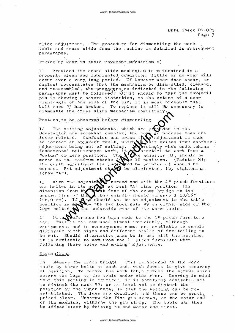
slido Rdjustment •. The procedure for dismnntling the work t?!bl(:: ?d1d cross slide from" the achinc- is detailed in s'ubsoquent pnragraphs.
T~·.king 11:] \\~C:B.r in tRblc i"!Ove;,"iGnt mG~ch~nism c)
11 Provided th.e crOSM ~lide I~ecll2ni5m is ~~~~ntn1ned ill Il
propGrly clean p.nd lubricated ·condit"ion, little or no woar will occur over R very long pcr~o~.· Tf however wear does occ~~, ~;r neglect n~cGssitates t!l~t the mechnnism be disrn~ntled. cleaned, and reassemb.led, t!:"~e proq.~_q:ttr~;\ .. as indicated in the following pFlrngraphs must be followed~· '~-If' ~ t should be tbnt the dovetail pin is showing 2 severe distortion, to the GXt811t of a near ~ight~ng10 on c~a side ef the pin, ~t is most probable that ball race 23 has broken. To roplnco it will li"e necessary to dismantle ttle crGSS slide rnGchnnis~ cCE:Jlstoly.
FacturD to be observed boiorc dismantling
12 TI,G setting adjust~ents, which nrc ~rovidcd in the Dov0t;:\il~ir :",.rc som-swhnt com.'"lex; the.; r,:cre; so b,'::cnuGC they ~rc , -inter-rcleted. Confusion can arise if An adjustment is onde to correct. Rn ap~a~~tit f~ult, which in fact arises from anoth8T ;:,djustm-~;::nt being out of setting. Accordingly l-rhe'n undertRking fundamentRl m~intenRpce ~ork, it is u~sentinl to ~ork from ~ Itdntum" 01: zero position. The stro\:c adjust0T 31, should be p~oved to th,.=! maximum stroke :figure 10 :-::osition. (PointeT E); the (iopth ~djustm0nt (as indicfltcd by ?ointur J) Sllould bo Zer08(!. Fi t adjus tm.-.:;n t should be ,-:-·limi 11;; tee!, (by tight(~.ning s cr(::w. "A It) •
1J With tile adjustments zeroed ~nd with the .llt pitch furniture car,: hRl ted in its norm?..l at r::;st :'A" line position, tho dimension from the front race of the cr~mp ~~idg~ to ihe centrp- ] i nc-: 01 th2 cllttf~r spinr11,~ shculd !'!1C.olS1,.1:rI? 1.13}16" (',6.0 mm). If t~is should not be so adjustment to the tabID position i~ made by the two lock nuts 99 on either side "of "the lug~ bolted to t~e lJndcrsido TORT of t~0 WDr~ t2ble.
Il: Note, ruf~r0nce I~~s b~~n mndc to ttlG 1" pitch rurniturG cam. This is the ca.m used al:nost inv- J'i<1bly, althougl: c~qllipm':nts. and in cons..:::qnenc0 c<:.ms. "re ;:n.rr;:_lablc to .::'np:.b10 di£j'arsyit ~itch sizes and di:ffoTent styJ0S of dovetAiling to be but. Shqtild alternative cams be in US0 with th0 m2chine, it is ad~igabl~ to wo* from the 111 pitcl\ furniture when i'ollowing these [lolet> i:::.nd mal<-ing·<1djustr.lents~
DismClnt1ing
15 Remove, the crnmp bridge. 'I'ti s is s(~cl..lrcd to the \vork ta.bJ.u by three bolts nt· cnch cnd, .. ·.d tll do\,'els tu giv0 ::.ccurF.cy of .)osition. To remove' tIt!? \vorl<: tF:bl£" Tc"::t()Ve the screws t..,·h:ich secure the lugs to the tf."ble" nnd~::-r side" r~.';::l.r. Dcnring in mind thnt this setting is c~itical, it" is som0titn0~ advisnblu net to disturb- the nuts 99; or (it lC.2st not to disturb tbe position o~ the inner nuts~ so ttl~t ttjC setting can bo rcest.::blished~ The lugs <1rc do\Vollet:~, ;,~ncl tl1csc: C:1.D be gently prised clear. Unscrew th':3 f'ive gib scr:cws, et the motop cnd of the machine, withdraw the gib strip_ The tublc cnn then he lifted"cl~nr by ~ai$ing ~t thci motor end first.
www.Dalt
onsW
adkin
.com
www.DaltonsWadkin.com
www.DaltonsWadkin.com
Data Sheet DS.025 :;Oage 4
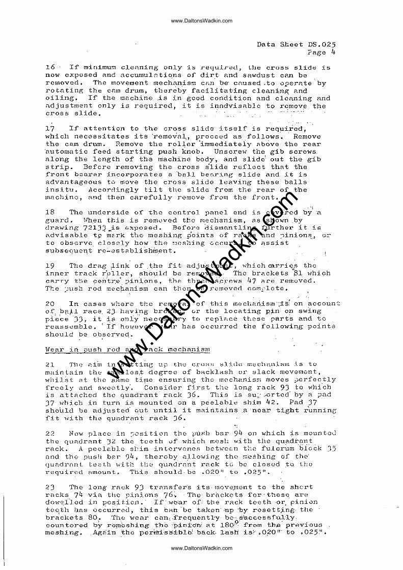
16 If minimu~ cle~\ning only is requir~d, tIle cross slide is now exposed and accumulntio,ns of dirt and sawdust c?~n be removed. The movement mechanis!W CF<n be' caused .to 01"JerRte by rotating the cam drum, thereby facilitating cleanin~ and oiling. If the machine .is in good condition and cleAning and adjustment only is required, it is i~ndvisable to r~mov~ the cross slide.
17 If attention to the cross slide itself is reguiied, which necessitates its 'removai, proceed as follows' ... Remove the cam drum. Remove the rol~'er °immediateiy "bove th.e rear 'automatic feed starting push knob. UnSCrel{ the gib sorews. along the length of the ~achine body, and slid~ out the gib strip. :Beforo removing the cross s'lide reflect that the front bearer incorporates a 'ball benring sl~de And it is advantageous to move the cross slide leaving these balls insitu. Accordingly tilt tIle slide from the rear of the machin'::, and the'n caref'ully remove from the front.
18 The underside o:f tb.G control panel end is cove'red b)/'a guard. ·~ ... 'h.en this is remuved the Pl€-chanism, as shown .by dral. .... ing 721J~_is (,;·xposed. Beforo dismnntling further it is advis?.ble -t9 mc-,rk the mesh.ing points of racks and :1inion.!1,.J u·::..~ to observe. closely how the ~cshing 0ccurs, to assist subsequeqt rC~GstRbli~h~~nt.
19 The drag ,link of' .the fit adju".stmc,nt, which carriE;.s tho inner track r'p'lle~t sh6uld bfJ remoyed., The brackets 'SI which CRT'ry tbe ~en:tr.e· ;..).in:.i,ons, thp. tbrnn S·.CT0.\IlS 47 r1re removed. T1:e :';1.1511 rod !r.ec~anism can then be removed comi-',lcte.
20 In cases wllcrc t~e removal of this meclla~ism':1s1-on account of ~~~~ race, 2), hRv~ng broken, er tIle locating pln bn sw~ng pi'e'ce '33" it ~$ only' necessary to rfrplf:ce these part's and to reassemble. ! If hO'ivGver '''eRr has occurred the follo1.Yi~g point.:3 should be obsGrved ..
1lear in push rod and rack mechanism
2l Tl1!J niin in setting -:"lP the: cros~ :::;lide nwchtlnlsm is to main tain the smallcs;t degre0 of bRcklash or slack movement r
whilst ~t the same ti~e ensuring the mcchanisni moves perfectly lrcGly and swontlY'. Considar f'irst the long rack 93 to ",hi'ch is attached the quadrant rack 36. This is su;: ~,ortcd' by <1 ;,Jad J7 which in turn is mounted on a peelabl-e shim 42. Pad 37 should be adjusted' ~ut until it mAin.tains _a 'near tight running fit with the qundr~nt rrick 36.
22 No-w place in :-,osi tion the i)ush bar 9l~ on ,,,,hich is moun"ta .... l the quadrFtnt 32 the teeth of which masl: \.,rith the quadr?nt rack. A peeleblc s~im ~ntcrvenes betw8Gn the fulcr~m '6i6~k 35 and the 'push ber 94, thcrGby 8),lot..ring the !7,'eshing of thc' quadrnnt teeth with tl:e guadrflnt rAc]( to be closed ~o the required cUllount.. This should· be ,,0-20'1 to .025 11 •
23 The long rack 93 trC'nsfer's its rnoveJnent to the shcrt racks 74 via tho .r:~inio·ns 76:. The- brackets for' thesq art~ dow~licd in po~iticn.· If' w~ar of: tbe rack teeth ,o~ pini0D tOG1th has occurred, this ca~ "be takon' ;ttp' 'by rosett,ing- the brackets 80. The wear can, .frequently beoS'\uccessf'ul·ly· coun te:red by rG"!II.cshing t'ho ''j:>i.ni:o'oi at 180,9, :from th.e' pr,,)vi,ou,s meshing. Aga'in ~thv pe:diTi·ss'ible~ back. Ta~rh is;' ~O,20'" to <>025,1I~
www.Dalt
onsW
adkin
.com
www.DaltonsWadkin.com
www.DaltonsWadkin.com
...... ¥
Dat~ Sheet DS.025 Page 5
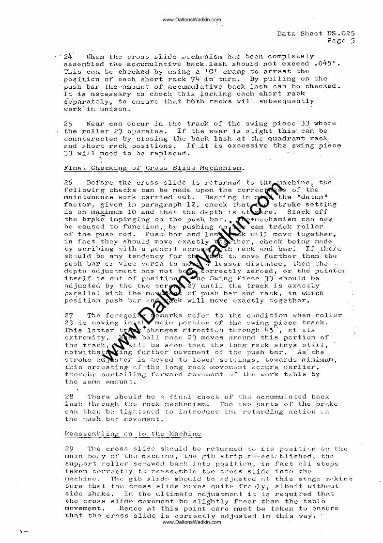
'24' l1hen the crvss slids ,i1(;;ch[l~isrn hr:.s been completely assembled the accurr.ula ti vC ba ck. lastl should not exceed .045 If •
This can be chi3ck~d by using a I C· j cramp to arrest the -po~i.tiGn of' each short rack 74" in" tu.rn. By pulling on the 'push bar the ,'nmou-nt of ac~umuJ ativ8 back lash CRn be checl{ed. It. is nece,ssary to cheel':: this :;Le.cLing each shcrt rack s·'.e"par?,-,tely-, to I.::DsUrG th?.t b6t~1 racks -,\iill subsequently' ioJork'in unison.
25 Wear eRn cccur in the track of the swing piece JJ where the r.oller 23 OpGTC'ltos ~ If' th.G. ,\Tc?-r is sligllt this' can. be counteracted by· closi::tg t!l<? bacl, lash at thG quadrant· racl, and short rRek 1JGsitions. If .. it "is oxcessive the s\,ling' piece JJ will pecd to be replacod.
FinRl Check~Ilg ()f Cross Slide Mechanism.
26 Befcre tr-.. e cruss slide is roturned tc th(..: mnchinG; ·tl-:.c following checks can be made upon the corroctness of' tGc main tenRnce ... ·lork cnrried out. Be.nring in mind the "dFl. tu~n tI factor, given in para.graph 12, cneck that the: s.tro.ke- setti11g is on inaximum 10 and that the: d0pth is ~~t zero. Slack 0.1·f the br.,Sll{.-;· impinging on the push bar. Th2 F"jGcbanisr;l C~;Ul n~\v, be caus·cd tu functiun,~ by pushing on the cam track rollGr of the push rod. Pus)} bOT 8nd long rack will move tug?theri in fact they should move eXRctly together, check .being ~ade by scrihing with a pencil Across bcth rack and b~~~ I~,th~rc sh·-:uld be any tendcncy for the rack t.:; mCJVG .furth(:r than th(~
push bRr 0~ vice versa to mOV0 a lesser distRnCG, then the depth ndjustment hns not bC0TI .correctly zeroed, or tl"lE"; .. pc..intel~ i ts::::lf is out of pasi tion. The Swing Piece 33· should be ,qdjusted by the- .t\'"'c screws 27 until the track is eXRctly parH.I·lnl wi th the m0vcmen t of push bRT and rack, in \vhi(::h position push b~r and rack will ~ove exactly togeth8r~
27 T!:tE: for(;going rcm('lrks refor to the condi tion when roller 23 is rr.oving in tLo m.s:in l:,cr·tion c·:f the:: ~~..,;dng Fiece tr~~k. This IFl.tter tr3.C~< chnnges c.~ircc·ti(Jn through 45·.1, C1.t its 8xtremi ty~ """;rThen b211 race 23 mCV8S around this ·pertion of the trRck, it will be S00n th;\t the long rack stays still, not'..'li ths tnnding lurthe:T mOVC:TI("!nt of tLo push bar. As· the stroke [.'..djuster is moved tu lo\vcr sc-t·tings r towards minimum, t~is arr8stin~ et ·tbG long rack 0lovo~ent ~)ccurs earlier, tL(.~roby curtniling rcrh'ard I"OV(;-m ... ::nt .;)1 Lhl_~ wcrk ti;~ble by the s nr'1C: RI!lCUn t .
28 There should be ? 1in[;1 check of' "the accumulated bac],,: lC1sh through the: rnck :::.ech;1nisf:l. The t-V!O ~Jarts 01 the br~kc CRn t.hen bl:.") tig.~-.. t.·8n(·d to introcuce t!:c rf..'t<1rding nction ,:. n the push bAr lnOv0m2nt.
[{(":.!<l.sscmbl ing en to tLc Ivi8.chinc
29 The cross slide' sl"i..culd b(: rcturn<:~d tz.' its positif.n (;Tl "t:1C Inain body cl' tllC machino, tile eib strip re-estrblished, the SUpl)Ort roller scr~wed back illtO pqsitiol1, in f~ct ~ll stops taken cl)rrectly to rc~ssep:blc tbe cr0SS slirle into tllU mPlchin(.'. Th.<.~ gib s.li.d(' shc·uld b\.) ;-djnstc'c! ;""!.t this stt~gQ :n"k.in.'~
S11re that the cross slide 8(:VGS quite frc~lYf plbeit with()ut sido shake. In tile ultimate ndjustment it is required thRt the cross slidE:' movement be slightly freer ·than the t<:lble: movement. Hence at this pOint care must be tr-lken tu ensure that the cross slide is correctly adjusted in thi~ way. -
www.Dalt
onsW
adkin
.com
www.DaltonsWadkin.com
www.DaltonsWadkin.com
Data Sheet DS.025 Page 6
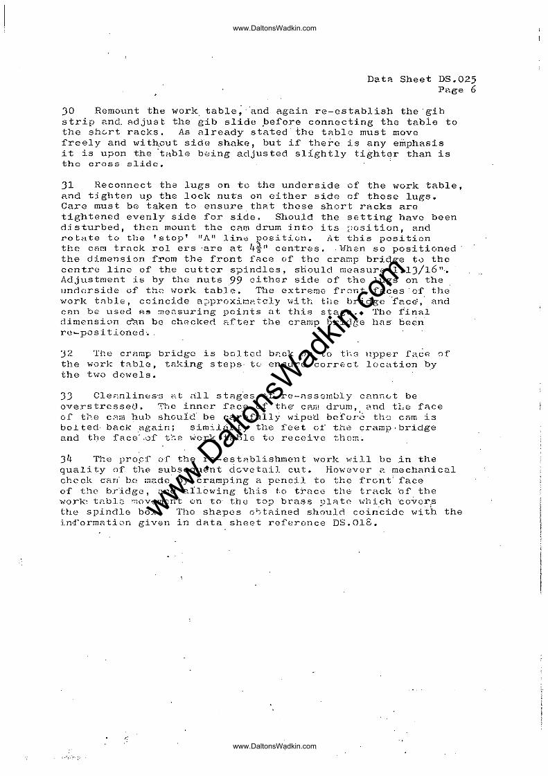
30 Remount the work table; oOand again re-establish the 0 gib strip ando adjust the gib slide perore connecting the tabie to the shGrt racks. As already stated the table must move freely and \vi th.out side shake, but if there is any emphasis it is upon the °tRble b"dng adjusted slightly tighter than is the cross slide.
31 Reconnect tha lugs on to the underside or the work table, and tighten up the lock nutos on oi ther side or theso lugs. Care must bG taken to ensure thRt those short racks are tightened evenly side ror side. Should the setting havo been disturbed, then mount the CRrn drum into its ~osition, and rotate to the I stop' nAil line position. ii.t this position the CEH'!l trnck roI ers -are at 4-111 cen.tres. . "L'lhen so posi tic.ned the dimension rrom the rront race or thc cramp bridge tu the contre line of the cutter spindlos, shOUld measure 1.1J/16 11
.•
Adjustment is by the nuts 99 either side or the lugs on the underside of the work table. TIle Gxtremo front faces'of the work tnble, coincide a~;pr(.JxiJ:!?_tC'ly \;1i th tile bridge -'face~t' and cnn. be used A.~ :TIc0.suring points nt this stag0_ The final dimension d'an be checked F~fter the cramp bridge 1185' been re .... posi tioned. '
:32 The cramp bridge is baIted bc:.ck on to ti-iG npper face of the work tA.ble, taking 5 teps' tc ensure corrc,; et Ioca tieD by the t,;o d01.els.
JJ Cle;,nlin8s's ,fl,t all stBg'es of re-assombly Canr10t be overstrcssetJ. 7.'h8 inner :fP-C'G ef the· cam drum, and tLe f'ace of the C<';;:TI hub shoulc' be car'efully wipetl befor~ th'3 Cam is bolted' back again; similtirly the feet ef the cramp,bridge and t4e fAce',of t~e ~6rk ·tRble to receivG thcm_
34 The propf 0f the re-e~tablishmGnt '"ark will be .in the quality o~ the subsequent dGvotail cut. However 2 mechanical check can' bE inade by tramping a pencil to the f'rcnt" face of the bridge, nnd al16wing this to t~acG the track hi' the work· table !'!10v-(~mont on to- the t:..),P brass -ulatc \'o'llich 'covDr,s the spindle box. The shepes o~tflined sh;uld coi~cidG wi~h the in~ormRti0n given in data sheet referonce DS.018.
;:
.',.'-.:,
www.Dalt
onsW
adkin
.com
www.DaltonsWadkin.com
www.DaltonsWadkin.com
Jl liAC.
CROSS TRA.Ve,RSE.
ftOL.LE.R. PAft.T No
uafa;~h~«et~~,~%P~.~ '''', - -·-".(Si:;'::~;
BRAKE. ADJIJSTMENT',J, AUTOMATIC. :nOVETAILER,
FIT A'D;:rUSTE.1t, SC ... EW 'A' (10)
BRAKE A:n::rUSTE.R SCREW (c;,1)
GU\'l>E. BRACKET
(SS)
BAit (.,+)
TABLE "'OTIO~
!<.OLLEIt..
PART NO. 2/12.540
FRONT G.UIl>E SR..Ac:.KET
" (5'»)
\ BR.AKE AJ).:rUSTER. 5CP.EW (107)
WIPE. EXCESS OIL
FROM THIS ARE.A.
www.Dalt
onsW
adkin
.com
www.DaltonsWadkin.com
www.DaltonsWadkin.com
IJ)/OFDfljj4riim.: ffll ' I~ . ,c. ~
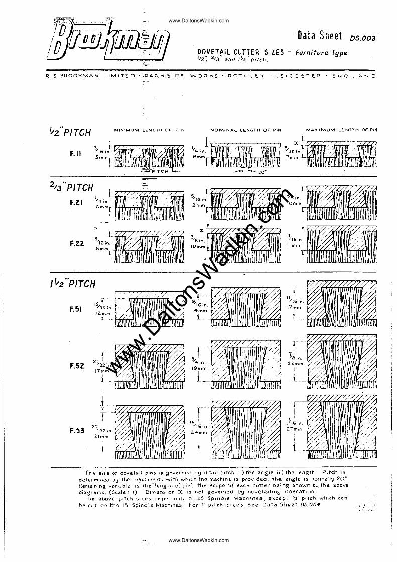
Data Sheet 05.003
DOVETAIL CUTTER SIZES - Furniture Type 1/2': 2/3" and I'/z" pitch.
R S.6ROOK""IAN LIMl1'£D '~P_ARIo<.S C'':: "":':J~.-o;S· ~CTk .... E."f I...E et. s"'r.P , ENG '- 0.......:
I"z"PITCH MINIMUM LENGTH O~ PIN NOMINAL LE.NGTH OF PIN MAX 1MUM LE.NGIH OF Pili
F.II
, , 1 .Kt.TItn ' 'uirtttiJ '~-1 vl6in. ~"" ,',:
5mmf i
1, ; " 4 ;n. 6mm,_
e..Jllllillli~ I': (!IOI/"/:
2/3 "PITCH
F.ZI
, LIf~'/~ x
" ' F.ZZ 5/'6;0 ~/~;~ IOB~:lIlIlIlW// /\\WIIIIf///,liillll I[mm 8 ,/. , ...
IYz"PfTCH //
F.SI r
IS""'}2 in.
I ., .... ' % :~~: ~111\ll\I~\\1\\\\~, 9/16io. <>:>'
14mm ,,' // I' '/: / ''/?'
F.Sl
F.53
IZrnlYl t
r-21 :
/32 in. 17rnm
i
i X
r 27/32 ;n.
21rTlIYI r,,'/
/ /
i;[
t .
r , ! V4in .
19mm
L~
r--, 15 '
;/16 in 2.4 mm
t
" " / I ' /, L_
r-7, i • ra.n.
22.mm
///
0< " ;/./ ~.ll \IJ if
~~ L,:(0\\
r-, '
1'16 in. 27mm
: L ,., !;;'<,{M,'I
The size of dovetail plM. IS gove.rned b~ i) the pITch 11) the angle 11i) the length. Pitch is
determined by the equlpments with which the machine IS provided, 1he. angle i~ normaily 20" Remaining Y'Mlabte is the "length of pin: the scope bf each ClJ1te.r being sho-wn by the. above di~grams" (Scale i I) DlmlZnSlon X L5 noT governe.d by d.ove:la"Lllng operation"
Ihe. above PITc.h SIl..e.S refe.r ooll,! fo 2.5 Spindle MaChines) except ... -;t.". Pllch whIch can be cuT on the 15 Spindle MlIchlrH~"s For r" pitch 51u:-5 see Oatll ShlZet DS.004.
ii.
www.Dalt
onsW
adkin
.com
www.DaltonsWadkin.com
www.DaltonsWadkin.com
\
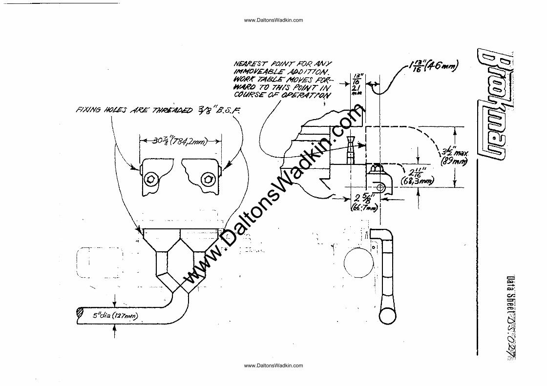
NFA,R£Sr .POINT RJR MlY INIf(OJl'GA8L£ AtlOI77'ON. WtJR-f" ?;1fBL£' .If(Of'.£S .FafWA,f'L) TO m/s IVQyr IN ctJVRS£ 01'" aP'£A"AfT/o<¥
i
www.Dalt
onsW
adkin
.com
www.DaltonsWadkin.com
www.DaltonsWadkin.com
'.
p
~ CUTTER
FEMALe: BOARD
5ELECTION CHART I MALE BOARD
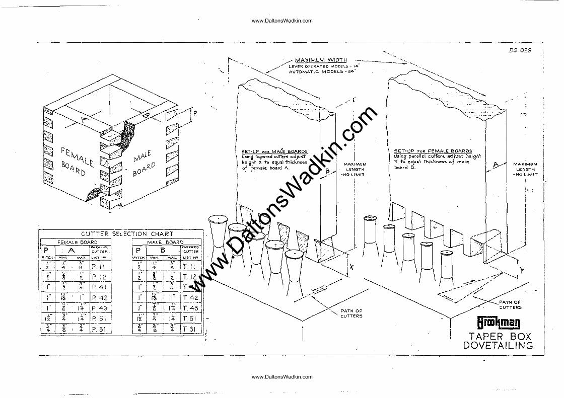
DS 029
r' , ....... ~~~ .... ~.
- /"" MA'::<IMUM WIDTH ----' _________ ,_-=:: ...... '. ........... ...../.,/- LEveR O?ER'ATED MOon.S - 14" ..•. , , , " _ AUTOMATIC MODEL5 - 24" .,
..................
\ '~ ( . ----... ) I
\ sET-loP ,.oR MA~E BOARDS
I,;
u~ing to.pered c.utte~ a.dju ... t height X To e~ual thic.kneS'S of f~ma'e board A.
, . !
1>. .. MAXIMUM
L.ENGTH ·NO lIM1i
~, PATH OF CuTTERS
SET-UP FOR FEMALE BOARDS Using paro\lel cutter'!! adjost rv.e.ight y to cC{.ua.\ thic.knes:~ of ma.le. board B.
MAXIMtJM LENGTH
-NO LIMIT
PATM OF CUTTERS
8rlD~ma" TAPER BOX
DOVETAILING
www.Dalt
onsW
adkin
.com
www.DaltonsWadkin.com
www.DaltonsWadkin.com