Embed Size (px)
Citation preview
Journal of Engineering Science, Vol. 15(2), 31–52, 2019
© Penerbit Universiti Sains Malaysia, 2019. This work is licensed under the terms of the Creative Commons Attribution (CC BY) (http://creativecommons.org/licenses/by/4.0/).
Automatic Circuit Breaker (ACB) for Low Voltage Substation Distribution System
Norazizah Norhafazid and Noramalina Abdullah*
School of Electrical and Electronic Engineering, Universiti Sains Malaysia, Engineering Campus, 14300 Nibong Tebal, Pulau Pinang, Malaysia
*Corresponding author: [email protected]
Published online: 31 December 2019To cite this article: Norazizah Norhafazid and Noramalina Abdullah (2019). Automatic circuit breaker (ACB) for low voltage substation distribution system. Journal of Engineering Science, 15(2), 31–52, https://doi.org/10.21315/jes2019.15.2.3.To link to this article: https://doi.org/10.21315/jes2019.15.2.3
Abstract: An automatic circuit breaker (ACB) is a device that acts on the occurrence of short circuits in power supply network. When a condition of contact division occurs, the extinction creates an interruption of current at a current’s high arc. At fault current zero passage, an arc is initially interrupted. The transient recovery voltage (TRV) recovering contact gap gives an adverse impact on dialectical of the network. By using current-limiting fuse (CLF) method, the usage of the over current can be easily reduced by clearing time at rated voltage to an interval equal. Two types of breaker models were used in the simulation design for comparison of the I–V graph. The protective relay was used in the design to detect and evaluate the fault. It also determined either to open or close the dedicated circuit. The system was simulated in one condition using two types of breaker models and their effects were observed. Analysis and evaluation of the automatic circuit breaker showed that this system was able to cut the over current limit and has the potential to prevent the usage of electrical energy due to the fault occurred.
Keywords: circuit breaker, current-limiting fuse, breaker model, protective relay and tripping
1. INTRODUCTION
Circuit breakers play their roles during short circuits at power supply network.1 It operates automatically when a fault is detected. The circuit breakers also have various size of switchgear to protect the circuit from low until high voltage.2 The automatic circuit breaker (ACB) has the potential to improve the distribution of low voltage (LV) in the LV substation and can identify the over limit electric current and automatically break the electric line. The aim is to avoid short
ACB for LV Substation 32
circuit and maintain the goodness of electric appliance. During an electrical fault, high fault currents up to several thousand amps can occur.3 Such fault currents need to be interrupted by a protective system. Fuse is one of the over current protections. During a fault condition, the inner conductor of the fuse will melt and interrupt the current flow.4 Fuses only can be used once, and the maximum current is limited when the fuse is interrupted. If this current exceeds the pickup value for a specific duration of time, the relay will send a trip order and the current path will be interrupted. Besides that, the characteristics of faults will be used as reference for the respective circuit breakers of each type of power transmission.2 There are no fixed parameters and causes for any type of fault. There are several factors that trigger a fault, such as:
1. Natural phenomenon,2. Instrument error,3. Human mistakes, 4. Setting error and5. Installation.
The protected system at substation is required from the generation station to control the voltage transmitted at high voltage. The most important thing in this project is to do the simulation on different types of breaker model using MATLAB Simulink software. When a fault is detected, sufficient data is required for the best possible decision making on the correct course of action. Thus, in this project, proper identification was made to detect the occurrence of fault and a simulation model was used to diagnose the fault. The outcome will automatically assist in cutting the overcurrent exceeding the limit, which is 100 A. When a fault occurs, the existed short-circuit currents goes beyond the interrupting capability of available circuit interrupters. Conventional types of interrupters are circuit breakers, distribution-circuit reclosers, and expulsion fuses. The use of current-limiting fuse (CLF) to protect individual distribution transformers is highly demanded.3
This article is organised as follows: Section 1 presents the introduction of ACB. Section 2 discuss on CLF. Section 3 presents the previous works related to ACB power system protection. Section 4 elaborates the methods suggested in this study. Section 5 presents simulation results and discussion. Finally, Section 6 describes about findings and contribution.
Journal of Engineering Science, Vol. 15(2), 31–52, 2019 33
2. CLF
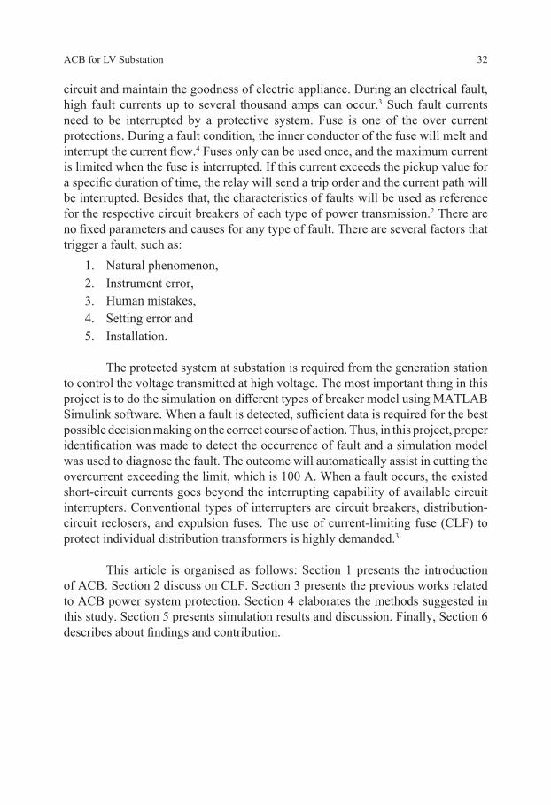
According to the UL 248-1, the CLF is defined as, “a fuse that, within a specified overcurrent range, limits the clearing time at rated voltage to an interval equal to or less than the first major or symmetrical current loop duration”.4 CLF is also used to prevent the occurrence of overcurrent in electric distribution system.5 For LV, high-rupturing-capacity (HRC) or NH fuse links is usually used for protection of LV electrical installations. Figure 1 shows the typical structure of the LV HRC.
Figure 1: The typical structure of LV HRC.2
3. RELATED WORKS
In general, the ACB functional is to avoid short circuit and maintain the goodness of electrical appliances. It has the potential to improve the distribution of LV in the LV substation and can identify the over limit electrical current and automatically break the electrical line. There are several methods proposed by the researchers to solve the problem faced by the industries, which is to limit the over current.

ACB for LV Substation 34
Overcurrent protection can be explained as an overload value of current, which contradicts with earth fault during short circuit and the rating value of electrical equipment. There are four classes of relay time-current characteristics:
1. Definite time relays, 2. Very inverse time relays, 3. Extremely inverse time relays, and 4. Inverse definite minimum time relays.
For this project, protection of over current will implement Inverse Definite Minimum Time (IDMT) relay. The risks of overcurrent could be reduced using the fuses, circuit breakers, temperature sensors, and current limiters.6 Power system protections act to protect the system during the occurrence of fault. It can automatically disconnect or trip the fault section at the power network. The protection is also able to minimise the interruption of power supply to the consumer. Such protection system is very important to protect humans and electrical network from any possible damage. Thus, it helps to retain the performance of system in terms of stability and reliability.7
Three components are used to act as a protection system, which is device (relay), circuit breaker, and instrument transformers (current transformers [CTs] and voltage transformers [VTs]). According to Institute of Electrical and Electronics Engineers (IEEE) standard, the relay is defined as “an electrical device” with the function of designing an interruption at input conditions in a structured manner. Upon fulfilling the requirement of conditions, it will give respond to similar abrupt changes in related electric control circuits.8 Thus, the faulted area will be separated with the help of protective relays. The circuit breaker will be monitored to give least interruption. With the previous explanation, the relay can be recognised as an automatic device to identify and measure abnormal conditions of electrical circuit. If such condition occurs, the relay will close its contact with the system.
The information and communication technology (ICT) system is the main reference for the operation of circuit breaker and relays. It provides the trip instruction if the fault condition occurs. Conditions of cables are also important in terms of cable sizing, cable parameters, and length of cable for the selection of circuit breaker. AC circuit breakers can be used for DC application. As the clearance time for DC fault is 0.5 sec, thus B-type circuit breaker can be used.9

Journal of Engineering Science, Vol. 15(2), 31–52, 2019 35
Current transformer provides a current proportional to the current flowing through the primary circuit. This condition is important for a protection device to ensure the performance of energy metering. During short circuit, the secondary is connected to the low impedance. Under the heading class X BS 3938, it is designated for the purpose of protection. By referring to the British Standard, class X is recognised as:
1. Rated secondary current, 2. Minimum knee-point voltage, 3. Maximum resistance of the secondary winding, and 4. Maximum magnetising current at the rated knee-point voltage (VK).
VK at the rated frequency is the voltage value applied to the secondary terminals. If the value of VK increases by 10%, the magnetising current will increase in maximum of 50% to give the secondary terminals a voltage proportional to that applied to the primary. However, for VT, the primary or secondary voltage ratio is constant. The important types are electromagnetic VT and capacitive VT, which refer to internal constriction. VT is used for protection in compliance with IEC 60044-2. The IEC accuracy classes are 3P and 6P. Usually, only class 3P will be used in practical. The accuracy class is guaranteed for the following values: voltages between 5% of the primary voltage and the maximum value of this voltage, which is the product of the primary voltage and the rated voltage factor which is kT × Un. For secondary load, the inductive power factor of 0.8 is the result between 25% and 100% of the accuracy.
4. METHODOLOGY
4.1 ACB Process
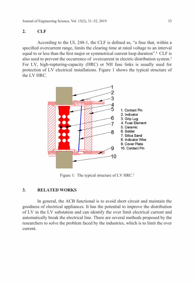
First, the simulation model was designed using MATLAB Simulink software. Next, two types of breaker model were used in this project, namely Simscape Power System breaker model and Simscape breaker model. Then, the data acquisition system was recorded. The value of load and current was analysed and it processed the data. Finally, from the value obtained, the current was tripped. These systems were to differentiate between breaker current and breaker voltage for two conditions of load more than 10 kW and load less than 10 kW. Figure 2 shows the related process.
ACB for LV Substation 36
Figure 2: Automatic circuit breaker process.
4.2 Project Implementation
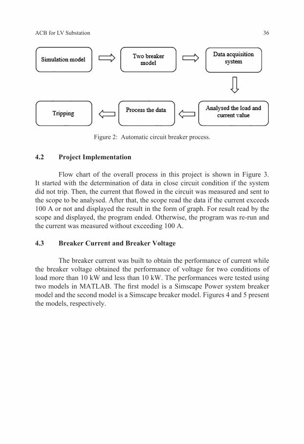
Flow chart of the overall process in this project is shown in Figure 3. It started with the determination of data in close circuit condition if the system did not trip. Then, the current that flowed in the circuit was measured and sent to the scope to be analysed. After that, the scope read the data if the current exceeds 100 A or not and displayed the result in the form of graph. For result read by the scope and displayed, the program ended. Otherwise, the program was re-run and the current was measured without exceeding 100 A.
4.3 Breaker Current and Breaker Voltage
The breaker current was built to obtain the performance of current while the breaker voltage obtained the performance of voltage for two conditions of load more than 10 kW and less than 10 kW. The performances were tested using two models in MATLAB. The first model is a Simscape Power system breaker model and the second model is a Simscape breaker model. Figures 4 and 5 present the models, respectively.
Journal of Engineering Science, Vol. 15(2), 31–52, 2019 37
Figure 3: Flowchart of the project.
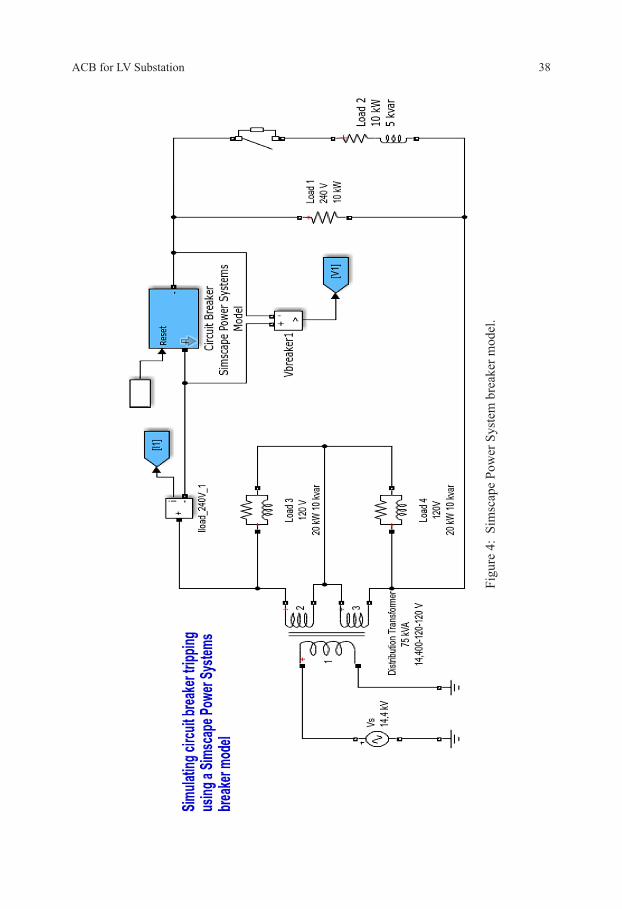
ACB for LV Substation 38
Figu
re 4
: Si
msc
ape
Pow
er S
yste
m b
reak
er m
odel
.

Journal of Engineering Science, Vol. 15(2), 31–52, 2019 39
Figu
re 5
: Si
msc
ape
brea
ker m
odel
.
ACB for LV Substation 40
5. RESULTS AND DISCUSSION
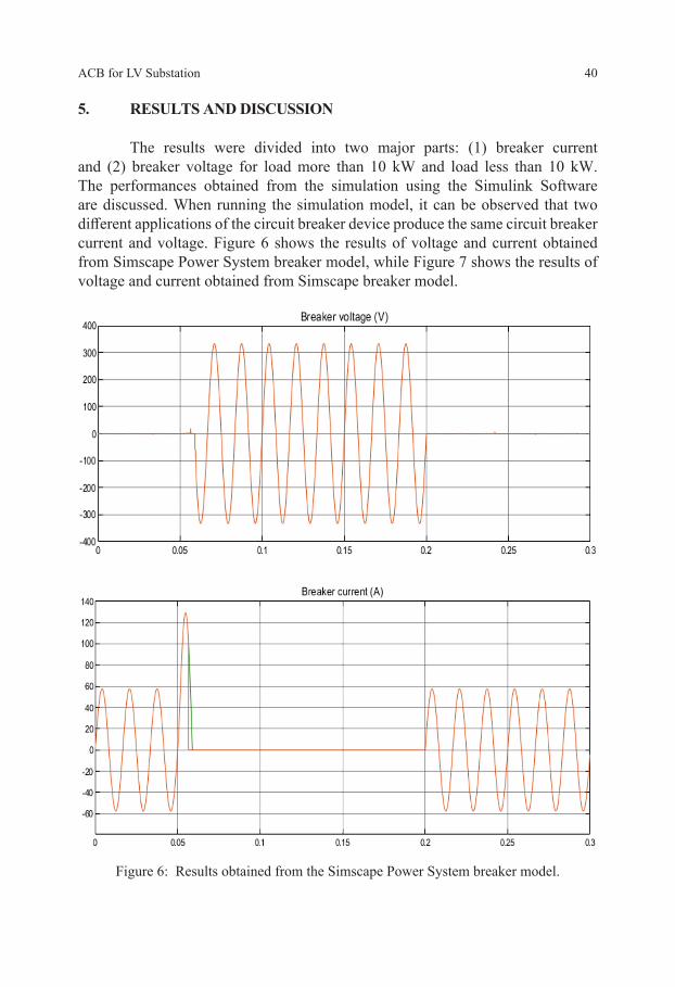
The results were divided into two major parts: (1) breaker current and (2) breaker voltage for load more than 10 kW and load less than 10 kW. The performances obtained from the simulation using the Simulink Software are discussed. When running the simulation model, it can be observed that two different applications of the circuit breaker device produce the same circuit breaker current and voltage. Figure 6 shows the results of voltage and current obtained from Simscape Power System breaker model, while Figure 7 shows the results of voltage and current obtained from Simscape breaker model.
Figure 6: Results obtained from the Simscape Power System breaker model.

Journal of Engineering Science, Vol. 15(2), 31–52, 2019 41
Figure 7: Results obtained from the Simscape breaker model.
From the results obtained, the Specialised Power System breaker model was superimposed with results from Simscape breaker model. The breaker current was interrupted at zero-crossing after the 100 A trip current setting exceeded.

ACB for LV Substation 42
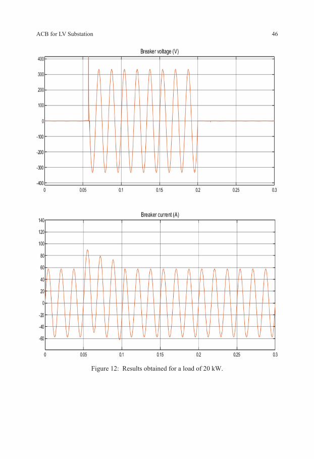
5.1 Current of Load More Than 10 kW
From the waveforms shown in Figure 8 until Figure 12, it was observed that when a load more than 10 kW was applied on the system, the result of breaker current was superimposed with the result from the breaker voltage. The applied load caused the current to exceed 100 A that had been set. Thus, the current automatically cut the electrical line.
Figure 8: Results obtained for a load of 12 kW.

Journal of Engineering Science, Vol. 15(2), 31–52, 2019 43
Figure 9: Results obtained for a load of 14 kW.

ACB for LV Substation 44
Figure 10: Results obtained for a load of 16 kW.

Journal of Engineering Science, Vol. 15(2), 31–52, 2019 45
Figure 11: Results obtained for a load of 18 kW.
ACB for LV Substation 46
Figure 12: Results obtained for a load of 20 kW.
Journal of Engineering Science, Vol. 15(2), 31–52, 2019 47
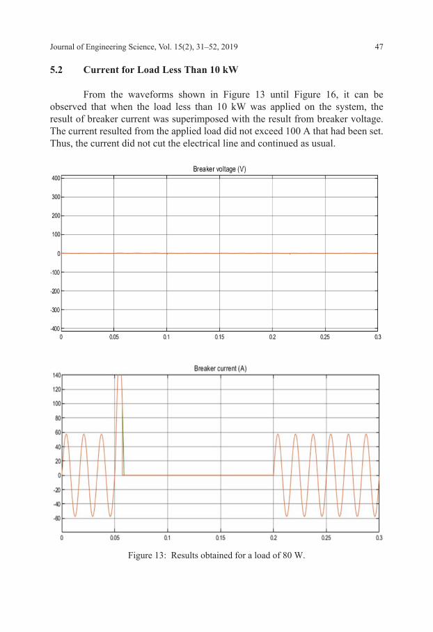
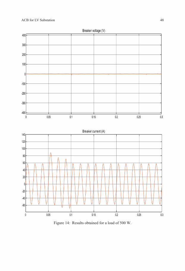
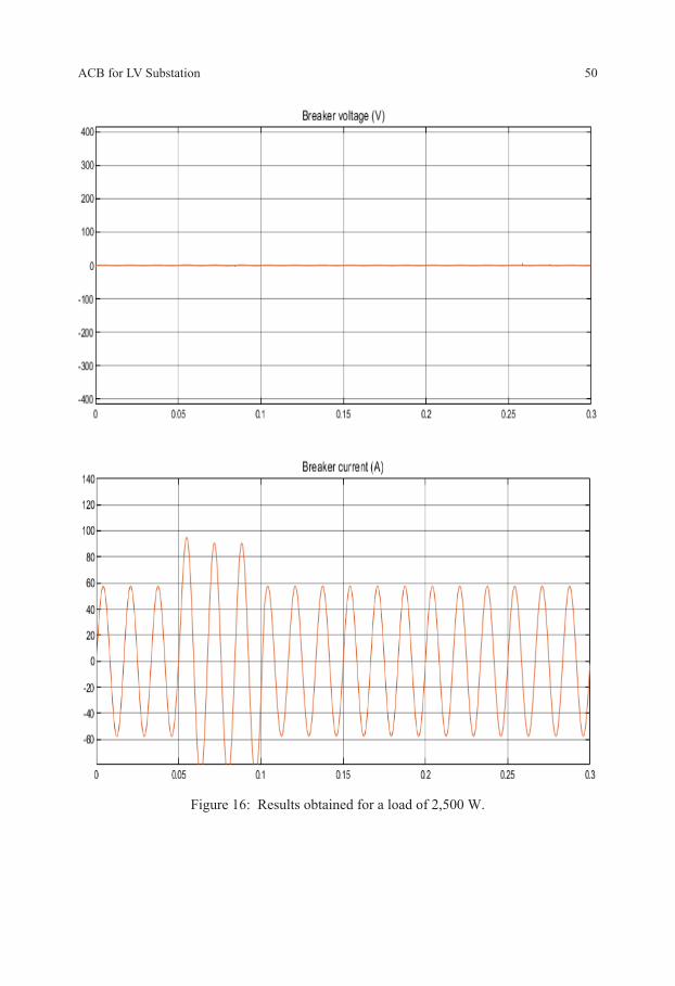
5.2 Current for Load Less Than 10 kW
From the waveforms shown in Figure 13 until Figure 16, it can be observed that when the load less than 10 kW was applied on the system, the result of breaker current was superimposed with the result from breaker voltage. The current resulted from the applied load did not exceed 100 A that had been set. Thus, the current did not cut the electrical line and continued as usual.
Figure 13: Results obtained for a load of 80 W.
ACB for LV Substation 48
Figure 14: Results obtained for a load of 500 W.

Journal of Engineering Science, Vol. 15(2), 31–52, 2019 49
Figure 15: Results obtained for a load of 1,000 W.
ACB for LV Substation 50
Figure 16: Results obtained for a load of 2,500 W.
Journal of Engineering Science, Vol. 15(2), 31–52, 2019 51
6. CONCLUSION
This article presents the Simulink model of two types of breaker models, namely Simscape Power System and Simscape breaker model simulated using Simscape Interface blocks of powerlib. The optimised values of the electric current that flowed through the circuit were determined. As a result, performance comparison was made between the breaker current and breaker voltage. From the comparison, this method was found to be most effective to automatically break the electric line exceeding 100 A. This system has successfully improved the distribution of LV in the LV substation.
7. ACKNOWLEDGEMENTS
The authors would like to acknowledge School of Electrical and Electronics Engineering, Universiti Sains Malaysia for providing necessary facilities for this study. We would like to express our greatest appreciation for the USM Short Term Grant 304/PELECT/60313049 received by the principal investigator that supported the project in publishing this article.
8. REFERENCES
1. Smeets, R. P. P. & Van der Linden, W. A. (2003). Current-zero measurements of vacuum circuit breakers interrupting short-line faults. IEEE T. Plasma Sci., 31(5), 852–858, https://doi.org/10.1109/TPS.2003.818438.
2. Psomopoulos, C. S., Barkas, D. A., Kaminaris, S. D., Ioannidis, G. C. & Karagiannopoulos, P. (2017). Recycling potential for low voltage and high voltage high rupturing capacity fuse links. Waste Manage., 70, 204–211, https://doi.org/10.1016/j.wasman.2017.09.018.
3. Brice, C. W., Dougal, R. A. & Hudgins, J. L. (1996). Review of technologies for current-limiting low-voltage circuit breakers. IEEE Trans. Ind. Appl., 32(5), 1005–1010, https://doi.org/10.1109/28.536858.
4. Valdes, M., Cline, C., Hansen, S. & Papallo, T. (2009). Selectivity analysis in low voltage power distribution systems with fuses and circuit breakers. Conference record 2009 IEEE industrial and commercial power systems technical conference. New Jersey, USA: Institute of Electrical and Electronics Engineers (IEEE), 1–10. https://doi.org/10.1109/ICPS.2009.5463937.
5. Kojovic, L. & Hassler, S. (1997). Application of current limiting fuses in distribution systems for improved power quality and protection. IEEE Trans. Power Del., 12(2), 791–800, https://doi.org/10.1109/61.584376.
6. Khan, S. (2013). Electrical safety of island operated low voltage DC network. MSc diss., Lappeenranta-Lahti University of Technology (LUT).
ACB for LV Substation 52
7. Popeck, C. A., Lewis, W. A. & Allen, G. D. (1977). The application of current limiting to distribution circuit protection. Electr. Pow. Syst. Res., 1(1), 67–86, https://doi.org/10.1016/0378-7796(77)90009-8.
8. Kasztenny, B. et al. (2011). Exploring the IEEE C37.234 guide for protective relay application to power system buses. 64th annual conference for protective relay engineers. New Jersey, USA: IEEE, 29–36, https://doi.org/10.1109/CPRE.2011.6035602.
9. Salonen, P., Nuutinen, P., Peltoniemi, P. & Partanen, J. (2009). Protection scheme for an LVDC distribution system. 20th international conference and exhibition on electricity distribution (CIRED 2009). London: IET, https://doi.org/10.1049/cp.2009.1053.