Embed Size (px)
Citation preview
Instruction BulletinRetain for future use.
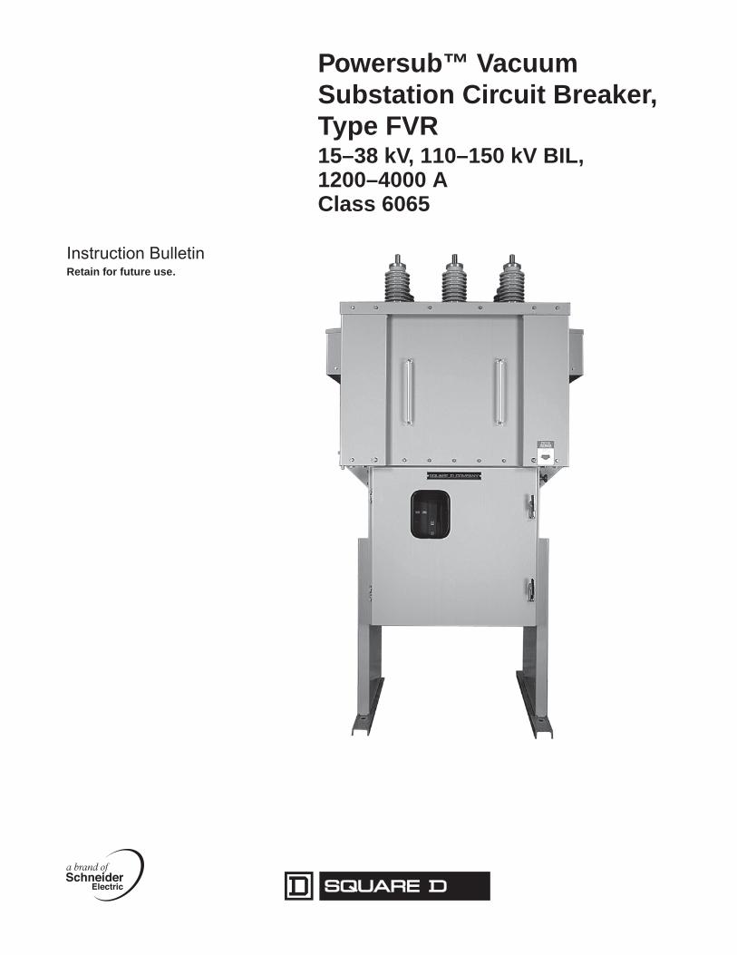
Powersub™ Vacuum Substation Circuit Breaker, Type FVR15–38 kV, 110–150 kV BIL, 1200–4000 AClass 6065

HAZARD CATEGORIES AND SPECIAL SYMBOLS
Read these instructions carefully and look at the equipment to become familiar with the device before trying to install, operate, service or maintain it. The following special messages may appear throughout this bulletin or on the equipment to warn of potential hazards or to call attention to information that clarifies or simplifies a procedure.
The addition of either symbol to a “Danger” or “Warning” safety label indicates that an electrical hazard exists which will result in personal injury if the instructions are not followed.
This is the safety alert symbol. It is used to alert you to potential personal injury hazards. Obey all safety messages that follow this symbol to avoid possible injury or death.
NOTE: Provides additional information to clarify or simplify a procedure.
PLEASE NOTE Electrical equipment should be installed, operated, serviced, and maintained only by qualified personnel. No responsibility is assumed by Schneider Electric for any consequences arising out of the use of this material.
DANGERDANGER indicates an imminently hazardous situation which, if not avoided, will result in death or serious injury.
WARNINGWARNING indicates a potentially hazardous situation which, if not avoided, can result in death or serious injury.
CAUTIONCAUTION indicates a potentially hazardous situation which, if not avoided, can result in minor or moderate injury.
CAUTIONCAUTION, used without the safety alert symbol, indicates a potentially hazardous situation which, if not avoided, can result in property damage.
6065-10 Powersub™ Vacuum Substation Circuit Breaker, Type FVR, 15–38 kV, 110–150 kV BIL, 1200–4000 A11/2005 Table of Contents
© 1995–2005 Schneider Electric All Rights Reserved 3
TABLE OF CONTENTSSection 1—Introduction ............................................................................ 5
Catalog Numbers ........................................................................................ 5
Section 2—Safety Precautions ................................................................. 6
Section 3—Receiving, Handling, and Storage ........................................ 7
Receiving .................................................................................................... 7Handling ...................................................................................................... 7Storage ....................................................................................................... 8Identification ................................................................................................ 8
Section 4—Description.............................................................................. 9
High Voltage Compartment ......................................................................... 9Vacuum Interrupters .............................................................................. 9Current Transformers .......................................................................... 10
Low Voltage Compartment ....................................................................... 10Operating Mechanism ......................................................................... 10Indicators ............................................................................................. 11Counter ................................................................................................ 11Closing Springs ................................................................................... 11Opening Springs .................................................................................. 12Motor Limit Switch ............................................................................... 12Spring Charging Motor ........................................................................ 12Auxiliary Switch ................................................................................... 12Trip and Close Coils ............................................................................ 12Anti-Pump Relay ................................................................................. 12Latch Check Switch ............................................................................. 12Heater Circuit ...................................................................................... 13
Heater Power Switch ..................................................................... 13Heater Thermostat......................................................................... 13
Manual Trip Reset Switch (69 Switch) ................................................ 13Low Voltage Instrument panel (Optional) .................................................. 15
Indicator Lights .................................................................................... 15Circuit Breaker Control Switch ............................................................ 15
Fan Cooling Circuit (4000 A circuit breakers only) ................................................................... 15
Fan Control Current Transformer (CT) ................................................ 16Current Sensing Relay (CSR) ............................................................. 16Fan Control Relay (CR) ....................................................................... 16Fan Test Switch (TF) ........................................................................... 16Fan Alarm Circuit ................................................................................. 16Alarm Time Delay ................................................................................ 16Air Flow Switches (FS1, FS2) ............................................................. 16
Section 5—Operation .............................................................................. 18
Charging the Closing Springs ................................................................... 18Closing Operation ..................................................................................... 18Opening Operation .................................................................................... 19
Manual Trip Operation ......................................................................... 19Manual Trip Reset Switch (69 Switch) ................................................ 19Electrical Trip Operation ...................................................................... 19
Fan Operation (4000 A circuit breakers only) ........................................... 19Automatic Operation ............................................................................ 19Manual Operation ................................................................................ 19
Powersub™ Vacuum Substation Circuit Breaker, Type FVR, 15–38 kV, 110–150 kV BIL, 1200–4000 A 6065-10Table of Contents 11/2005
© 1995–2005 Schneider Electric All Rights Reserved4
Section 6—Installation............................................................................. 20
Foundation ................................................................................................ 20Lifting the Circuit Breaker .......................................................................... 21Grounding ................................................................................................. 21Initial Circuit Breaker Preparation ............................................................. 21Arc-Resistance Feature ............................................................................ 22Cable Connection ...................................................................................... 23Pre-Operation Tests .................................................................................. 24
Section 7—Maintenance .......................................................................... 25
General Inspection .................................................................................... 25Insulating Surfaces .................................................................................... 26Air Filters ................................................................................................... 26Vacuum Interrupters .................................................................................. 26
Contact Erosion ................................................................................... 26E-Gap .................................................................................................. 27Contact Gap ........................................................................................ 28Hi-Pot (Dielectric) Test ........................................................................ 28Contact Resistance Measurement ...................................................... 28
Lubrication ................................................................................................. 29Lubrication Intervals ............................................................................ 29Lubrication Points During Maintenance ............................................... 29
Section 8—Replacement Parts ............................................................... 31
Section 9—Maintenance Log .................................................................. 33
LIST OF FIGURES Figure 1: 110 kV BIL to 150 kV BIL, Type FVR Vacuum Circuit Breaker, Front View ................................................... 9
Figure 2: Vacuum Interrupter Assembly ............................................. 10Figure 3: High Voltage Compartment Interior ..................................... 10Figure 4: Operating Mechanism (Two Views with and without
Mechanism Cover) ............................................................... 11Figure 5: Low Voltage Compartment, Rear View ................................ 13Figure 6: Typical Control Schematic—Breaker in Open Position,
Springs Discharged. ............................................................ 14Figure 7: Low Voltage Instrument Panel (optional) ............................. 15Figure 8: Typical Fan Control Schematic, 4000 A Circuit Breaker
(see customer order drawings for actual schematic) ........... 17Figure 9: Gear and Ratchet Detail ...................................................... 18Figure 10: Plan View for Type FVR Circuit Breaker .............................. 20Figure 11: Vent Covers ......................................................................... 22Figure 12: Vent Deflectors .................................................................... 23Figure 13: Vent Lids .............................................................................. 23Figure 14: Air Filter Locations ............................................................... 26Figure 15: Measuring E-Gap ................................................................. 27Figure 16: Vacuum Interrupter Assembly ............................................. 28Figure 17: Lubrication Points ................................................................ 29Figure 18: Lubrication Point Details ...................................................... 30
LIST OF TABLES Table 1: Catalog Numbering Scheme.................................................. 5Table 2: Hi-Pot Test Voltages............................................................ 24Table 3: Inspection Intervals.............................................................. 25Table 4: Nominal E-Gap Settings ...................................................... 27Table 5: Resistance Measurement Values........................................ 28Table 6: Lubrication Intervals............................................................. 29Table 7: Replacement Parts .............................................................. 31

6065-10 Powersub™ Vacuum Substation Circuit Breaker, Type FVR, 15–38 kV, 110–150 kV BIL, 1200–4000 A11/2005 Section 1—Introduction
© 1995–2005 Schneider Electric All Rights Reserved 5
SECTION 1—INTRODUCTION This bulletin contains instructions for installation, operation, and maintenance of Square D® Powersub™ Type FVR series circuit breakers (up to 150 kV BIL) manufactured by Schneider Electric.
It is important to read and understand this bulletin completely before performing the installation, operation, and maintenance steps provided. Electrical equipment should be installed and serviced only by qualified personnel. Qualified personnel should establish procedures that ensure the safety of personnel and equipment.
The Type FVR circuit breaker is designed for outdoor substation applications and provides interrupting capability for medium voltage systems up to 38 kV. Circuits in which these circuit breakers are placed are capable of overvoltages. Complex medium voltage systems may require a detailed overvoltage system analysis and the addition of overvoltage protection.
All Type FVR circuit breakers, except those rated at or above 3000 A, have been designed with an arc-resistant enclosure. The 4000 A rating requires the use of a fan circuit.
CATALOG NUMBERS The following is an explanation and sample of the catalog numbering scheme:
Table 1: Catalog Numbering Scheme
Type VoltageClass
Continuous CurrentRating
BIL Rating Interrupting Rating
SeriesDesignation
FVR—Vacuum
1 = 15 kV
2 = 27 kV
3 = 38 kV
06 = 600 A
08 = 800 A
12 = 1200 A
20 = 2000 A
30 = 3000 A
35 = 3500 A
40 = 4000 A1
1 Fan cooled
11 = 110 kV
12 = 125 kV
15 = 150 kV
12 = 12.5 kA
16 = 16 kA
20 = 20 kA
25 = 25 kA
31 = 31.5 kA
40 = 40 kA
A
Catalog Number—FVR 1 12 11 16 A
Series Designation
Interrupting Rating
BIL Rating
Continuous Current Rating
Voltage Class
Type
Powersub™ Vacuum Substation Circuit Breaker, Type FVR, 15–38 kV, 110–150 kV BIL, 1200–4000 A 6065-10Section 2—Safety Precautions 11/2005
© 1995–2005 Schneider Electric All Rights Reserved6
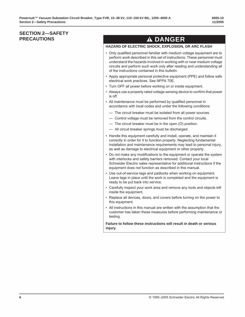
SECTION 2—SAFETY PRECAUTIONS DANGER
HAZARD OF ELECTRIC SHOCK, EXPLOSION, OR ARC FLASH
• Only qualified personnel familiar with medium voltage equipment are to perform work described in this set of instructions. These personnel must understand the hazards involved in working with or near medium voltage circuits and perform such work only after reading and understanding all of the instructions contained in this bulletin.
• Apply appropriate personal protective equipment (PPE) and follow safe electrical work practices. See NFPA 70E.
• Turn OFF all power before working on or inside equipment.
• Always use a properly rated voltage sensing device to confirm that power is off.
• All maintenance must be performed by qualified personnel in accordance with local codes and under the following conditions:
— The circuit breaker must be isolated from all power sources.
— Control voltage must be removed from the control circuits.
— The circuit breaker must be in the open (O) position.
— All circuit breaker springs must be discharged.
• Handle this equipment carefully and install, operate, and maintain it correctly in order for it to function properly. Neglecting fundamental installation and maintenance requirements may lead to personal injury, as well as damage to electrical equipment or other property.
• Do not make any modifications to the equipment or operate the system with interlocks and safety barriers removed. Contact your local Schneider Electric sales representative for additional instructions if the equipment does not function as described in this manual.
• Use out-of-service tags and padlocks when working on equipment. Leave tags in place until the work is completed and the equipment is ready to be put back into service.
• Carefully inspect your work area and remove any tools and objects left inside the equipment.
• Replace all devices, doors, and covers before turning on the power to this equipment.
• All instructions in this manual are written with the assumption that the customer has taken these measures before performing maintenance or testing.
Failure to follow these instructions will result in death or serious injury.
6065-10 Powersub™ Vacuum Substation Circuit Breaker, Type FVR, 15–38 kV, 110–150 kV BIL, 1200–4000 A11/2005 Section 3—Receiving, Handling, and Storage
© 1995–2005 Schneider Electric All Rights Reserved 7
SECTION 3—RECEIVING, HANDLING, AND STORAGE
RECEIVING Upon receipt, check the packing list against the equipment received to ensure the order and shipment are complete. Claims for shortages or errors must be made in writing to Schneider Electric within 60 days after delivery. Failure to give such notice will constitute unqualified acceptance and a waiver of all such claims by the purchaser.
Immediately inspect the equipment for any damage which may have occurred in transit. If damage is found or suspected, file a claim with the carrier immediately and notify Schneider Electric. Delivery of equipment to a carrier at any of the Schneider Electric plants or other shipping points constitutes delivery to the purchaser regardless of freight payment and title. All risk of loss or damage pass to the purchaser at that time.
For details concerning claims for equipment shortages and other errors, refer to Schneider Electric “Terms and Conditions of Sale”.
HANDLING Lifting eyes (Figure 1 on page 9) are provided on the roof of the Type FVR circuit breaker for lifting by crane. No spreader bars are required. Handle the equipment with care. Protect the bushings from rough treatment to avoid chipping.
If lifting the circuit breaker by forklift, place the forklift forks underneath the low voltage compartment (Figure 1 on page 9), and secure the circuit breaker to the forklift with a strap. The floor of the low voltage compartment is reinforced to support the weight of the circuit breaker. Do not lift the circuit breaker by the side vent housings or any other protrusions. If another handling method is necessary, contact Schneider Electric to make special preparations.
View the OPEN-CLOSED indicator (Figure 4 on page 11) to verify the mechanism/breaker position. The Type FVR circuit breaker is shipped with the breaker in the closed position.
WARNINGTOP HEAVY LOAD
If lifting the circuit breaker by forklift, stabilize the circuit breaker with a safety strap to reduce the possibility of tipping.
Failure to follow this instruction can result in death or serious injury.
CAUTIONDO NOT LIFT CIRCUIT BREAKER BY SIDE VENT HOUSINGS
Damaged vent housings can constrict proper air flow and expose the interior of the high voltage compartment to weather.
Failure to follow this instruction can result in equipment damage.
Powersub™ Vacuum Substation Circuit Breaker, Type FVR, 15–38 kV, 110–150 kV BIL, 1200–4000 A 6065-10Section 3—Receiving, Handling, and Storage 11/2005
© 1995–2005 Schneider Electric All Rights Reserved8
STORAGE If the circuit breaker must be stored before operation, keep it in an area that provides protection from damage. Inspect the circuit breaker regularly when stored for prolonged periods.
NOTE: The Type FVR circuit breaker is equipped with strip heaters that must be energized during storage to prevent condensation within the circuit breaker housing. Verify that the heater thermostat is set at 75 °F (24 °C).
IDENTIFICATION The rating nameplate is located on the inside of the rear low-voltage door and includes the following information:
• Catalog number
• Customer purchase order number
• Serial number
• Weight (lbs)
• Maintenance manual number
• Manufacture date
• Factory order number
• Control diagram number
• Rated maximum voltage (kV RMS)
• Full wave BIL (kV Pk)
• Rated frequency (Hz)
• One minute withstand (kV RMS)
• Interrupt time (cycles)
• Closing time (cycles)
• Close and latch (kA Pk)
• Reclosing time (cycles)
• Duty cycle (O–CO–15 seconds–CO)
• Rated continuous current (A RMS)
• Rated short circuit current (kA RMS)
• Charging motor voltage
• Closing coil voltage
• Tripping coil 1 voltage
• Tripping coil 2 voltage
• Spare auxiliary switch contacts
6065-10 Powersub™ Vacuum Substation Circuit Breaker, Type FVR, 15–38 kV, 110–150 kV BIL, 1200–4000 A11/2005 Section 4—Description
© 1995–2005 Schneider Electric All Rights Reserved 9
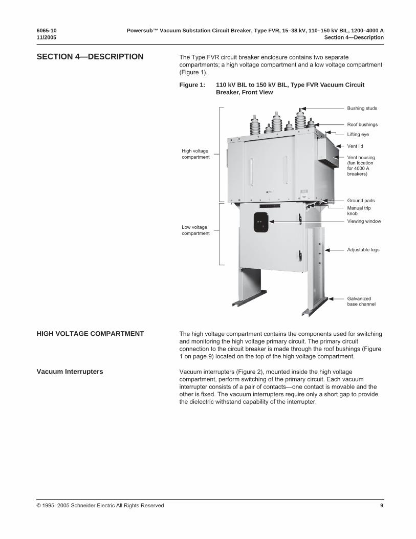
SECTION 4—DESCRIPTION The Type FVR circuit breaker enclosure contains two separate compartments; a high voltage compartment and a low voltage compartment (Figure 1).
HIGH VOLTAGE COMPARTMENT The high voltage compartment contains the components used for switching and monitoring the high voltage primary circuit. The primary circuit connection to the circuit breaker is made through the roof bushings (Figure 1 on page 9) located on the top of the high voltage compartment.
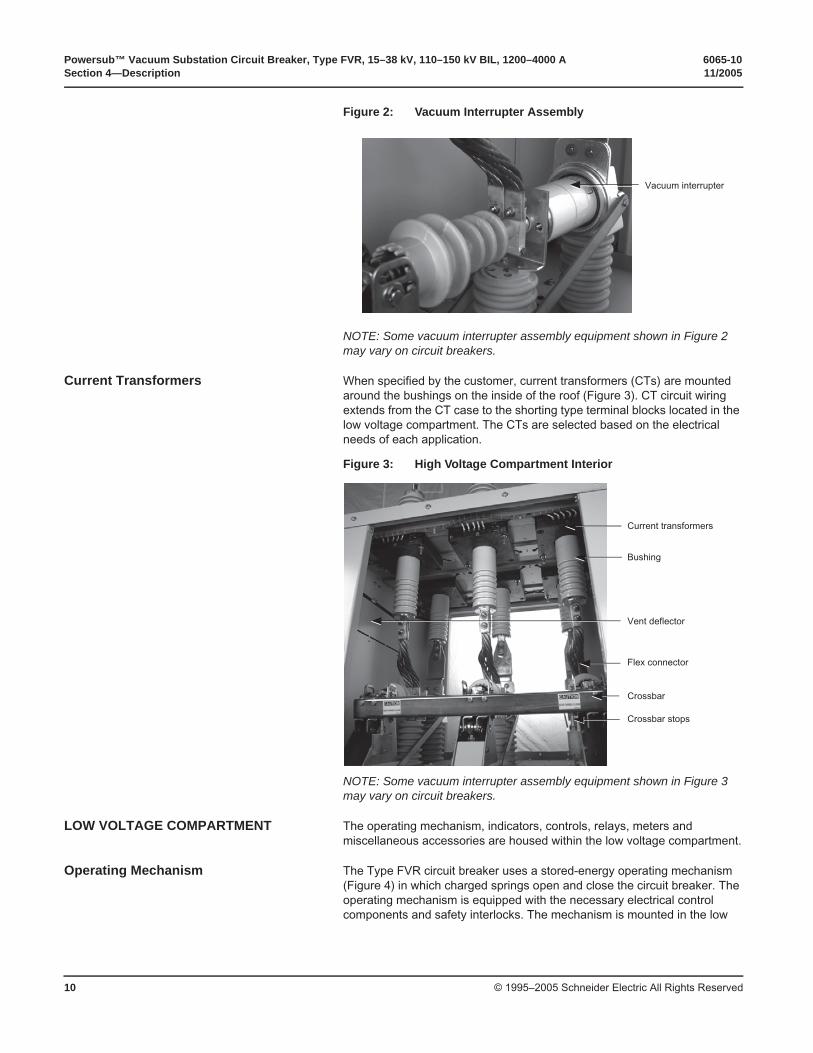
Vacuum Interrupters Vacuum interrupters (Figure 2), mounted inside the high voltage compartment, perform switching of the primary circuit. Each vacuum interrupter consists of a pair of contacts—one contact is movable and the other is fixed. The vacuum interrupters require only a short gap to provide the dielectric withstand capability of the interrupter.
Figure 1: 110 kV BIL to 150 kV BIL, Type FVR Vacuum Circuit Breaker, Front View
High voltagecompartment
Low voltagecompartment
Bushing studs
Roof bushings
Lifting eye
Vent lid
Vent housing(fan location for 4000 A breakers)
Ground pads
Manual trip knob
Viewing window
Adjustable legs
Galvanizedbase channel
Powersub™ Vacuum Substation Circuit Breaker, Type FVR, 15–38 kV, 110–150 kV BIL, 1200–4000 A 6065-10Section 4—Description 11/2005
© 1995–2005 Schneider Electric All Rights Reserved10
NOTE: Some vacuum interrupter assembly equipment shown in Figure 2 may vary on circuit breakers.
Current Transformers When specified by the customer, current transformers (CTs) are mounted around the bushings on the inside of the roof (Figure 3). CT circuit wiring extends from the CT case to the shorting type terminal blocks located in the low voltage compartment. The CTs are selected based on the electrical needs of each application.
NOTE: Some vacuum interrupter assembly equipment shown in Figure 3 may vary on circuit breakers.
LOW VOLTAGE COMPARTMENT The operating mechanism, indicators, controls, relays, meters and miscellaneous accessories are housed within the low voltage compartment.
Operating Mechanism The Type FVR circuit breaker uses a stored-energy operating mechanism (Figure 4) in which charged springs open and close the circuit breaker. The operating mechanism is equipped with the necessary electrical control components and safety interlocks. The mechanism is mounted in the low
Figure 2: Vacuum Interrupter Assembly
Vacuum interrupter
Figure 3: High Voltage Compartment Interior
Current transformers
Crossbar stops
Bushing
Vent deflector
Flex connector
Crossbar
6065-10 Powersub™ Vacuum Substation Circuit Breaker, Type FVR, 15–38 kV, 110–150 kV BIL, 1200–4000 A11/2005 Section 4—Description
© 1995–2005 Schneider Electric All Rights Reserved 11
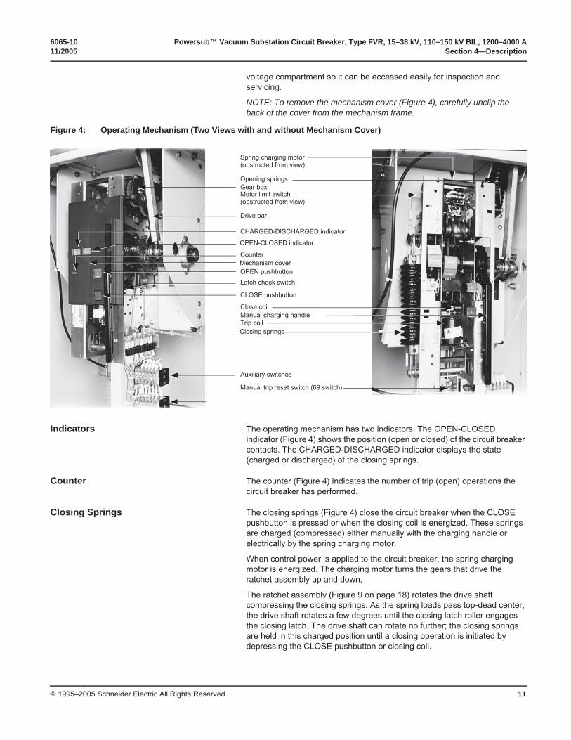
voltage compartment so it can be accessed easily for inspection and servicing.
NOTE: To remove the mechanism cover (Figure 4), carefully unclip the back of the cover from the mechanism frame.
Indicators The operating mechanism has two indicators. The OPEN-CLOSED indicator (Figure 4) shows the position (open or closed) of the circuit breaker contacts. The CHARGED-DISCHARGED indicator displays the state (charged or discharged) of the closing springs.
Counter The counter (Figure 4) indicates the number of trip (open) operations the circuit breaker has performed.
Closing Springs The closing springs (Figure 4) close the circuit breaker when the CLOSE pushbutton is pressed or when the closing coil is energized. These springs are charged (compressed) either manually with the charging handle or electrically by the spring charging motor.
When control power is applied to the circuit breaker, the spring charging motor is energized. The charging motor turns the gears that drive the ratchet assembly up and down.
The ratchet assembly (Figure 9 on page 18) rotates the drive shaft compressing the closing springs. As the spring loads pass top-dead center, the drive shaft rotates a few degrees until the closing latch roller engages the closing latch. The drive shaft can rotate no further; the closing springs are held in this charged position until a closing operation is initiated by depressing the CLOSE pushbutton or closing coil.
Figure 4: Operating Mechanism (Two Views with and without Mechanism Cover)
Spring charging motor (obstructed from view)
Motor limit switch (obstructed from view)
Gear boxOpening springs
Drive bar
CHARGED-DISCHARGED indicator
OPEN-CLOSED indicator
CounterMechanism coverOPEN pushbutton
Latch check switch
CLOSE pushbutton
Closing springs
Close coilManual charging handleTrip coil
Auxiliary switches
Manual trip reset switch (69 switch)
Powersub™ Vacuum Substation Circuit Breaker, Type FVR, 15–38 kV, 110–150 kV BIL, 1200–4000 A 6065-10Section 4—Description 11/2005
© 1995–2005 Schneider Electric All Rights Reserved12
Opening Springs The opening springs (Figure 4 on page 11) open the circuit breaker when the OPEN pushbutton is pressed or the trip coil is energized. These springs are charged (compressed) whenever the circuit breaker is in the closed position.
Motor Limit Switch The motor limit switch (Figure 4 on page 11) energizes the spring charging motor during the charging operation of the mechanism. At the same time, the motor limit switch disables the closing coil circuit. Once the closing springs are fully charged, the motor limit switch de-energizes the spring charging motor.
Spring Charging Motor When energized by the closing of the motor limit switch, the spring charging motor (Figure 4 on page 11) drives the series of connected gears and cam. The cam then raises and lowers the ratchet assembly and rotates the drive shaft. As the drive shaft rotates, the closing springs compress to the charged position. When the closing springs are fully charged, the motor limit switch contacts open, de-energizing the spring charging motor.
Auxiliary Switch The auxiliary switch (Figure 4 on page 11) is a multi-contact switch used to operate circuits that are dependent upon the position of the primary circuit breaker contacts. The schematic diagram on page 14 indicates how each of the auxiliary switch contacts interconnect with the circuit breaker circuitry. The following describes the function of each stage:
• Two sets of normally open, 52/a contacts are connected in series with the trip coil (52/TC) to de-energize the trip coil when the circuit breaker is in the open position.
• One normally closed, 52/b contact is connected in series with the closing coil (52/CC) to de-energize the closing coil when the circuit breaker is in the closed position.
• For user convenience, additional a- and b-type contacts are included for optional use.
Trip and Close Coils The trip and close coils (Figure 4 on page 11) are located in the lower center of the operating mechanism. When energized, these coils release the open or close latches located inside the mechanism.
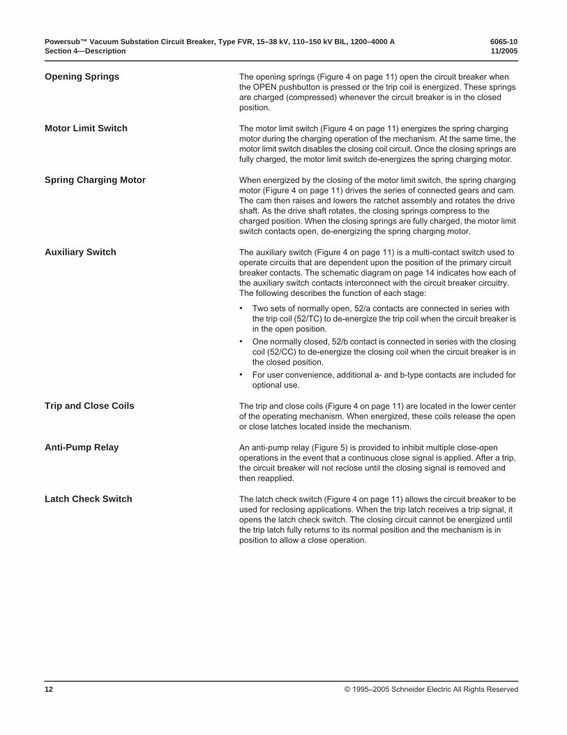
Anti-Pump Relay An anti-pump relay (Figure 5) is provided to inhibit multiple close-open operations in the event that a continuous close signal is applied. After a trip, the circuit breaker will not reclose until the closing signal is removed and then reapplied.
Latch Check Switch The latch check switch (Figure 4 on page 11) allows the circuit breaker to be used for reclosing applications. When the trip latch receives a trip signal, it opens the latch check switch. The closing circuit cannot be energized until the trip latch fully returns to its normal position and the mechanism is in position to allow a close operation.
6065-10 Powersub™ Vacuum Substation Circuit Breaker, Type FVR, 15–38 kV, 110–150 kV BIL, 1200–4000 A11/2005 Section 4—Description
© 1995–2005 Schneider Electric All Rights Reserved 13
Heater Circuit In normal configurations, two strip heaters (Figure 5) are mounted on the rear of the operating mechanism to reduce condensation. In some applications, additional heaters may be used.
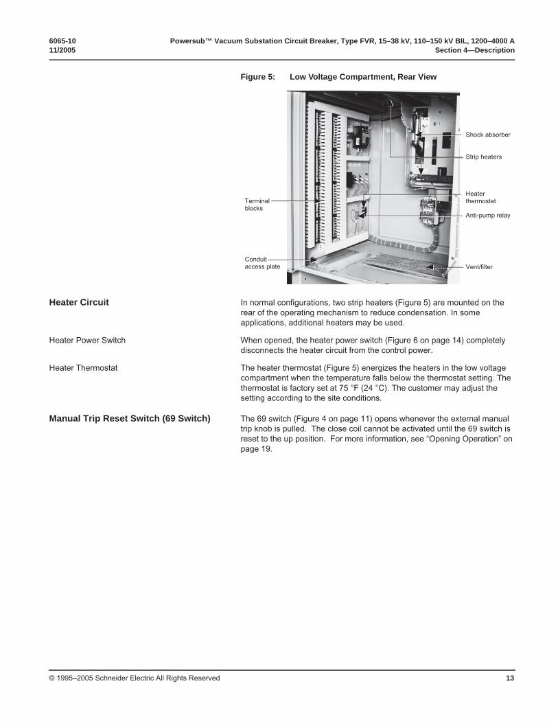
Heater Power Switch When opened, the heater power switch (Figure 6 on page 14) completely disconnects the heater circuit from the control power.
Heater Thermostat The heater thermostat (Figure 5) energizes the heaters in the low voltage compartment when the temperature falls below the thermostat setting. The thermostat is factory set at 75 °F (24 °C). The customer may adjust the setting according to the site conditions.
Manual Trip Reset Switch (69 Switch) The 69 switch (Figure 4 on page 11) opens whenever the external manual trip knob is pulled. The close coil cannot be activated until the 69 switch is reset to the up position. For more information, see “Opening Operation” on page 19.
Figure 5: Low Voltage Compartment, Rear View
Terminal blocks
Shock absorber
Conduit access plate
Strip heaters
Heater thermostat
Anti-pump relay
Vent/filter
Powersub™ Vacuum Substation Circuit Breaker, Type FVR, 15–38 kV, 110–150 kV BIL, 1200–4000 A 6065-10Section 4—Description 11/2005
© 1995–2005 Schneider Electric All Rights Reserved14
Figure 6: Typical Control Schematic—Breaker in Open Position, Springs Discharged.
CircuitClose Coil
CircuitBreaker Status
Open
10
AC/DCSOURCE
15 A
3 51
2 4 6
52/LS
5
6
52/M
1
2
6
52/CC
1
2
52/LS1
2
52/LC2
1
52/b9
10
52/Y4
69
1
3
CS/C
52/a
7
852/Y
6
8
52/Y
2
7
14 16
5 41
52/b13
1452/a
15
16
1513
CS/T
52/a4
3
52/a11
12
52/TC
1
2
(-)
4
5 97
(+)
9
Heater Circuit
(Each heater rated 240 V, 500 W)
240 VacVV
8H
31
2 4
35
36
HTR
HTR
GG R
52/Y
1
3
MOV
Circuit
23
10 A
10 A
LEGEND
52/M Spring Charging Motor 52/LC Latch Check Switch
52/Y Anti-pump Relay 52/LS Motor Limit Switch
CS Circuit Breaker Control Switch 52/CC Close Coil
52/aAuxiliary Switch
(Open When Circuit Breaker is Open)
52//TC Trip Coil
8C Control Power Switch
52/bAuxiliary Switch
(Closed When Circuit Breaker is Open)69 Manual Trip Reset Switch
(69 switch)
23 Heater Thermostat 8H Heater Power Switch
6065-10 Powersub™ Vacuum Substation Circuit Breaker, Type FVR, 15–38 kV, 110–150 kV BIL, 1200–4000 A11/2005 Section 4—Description
© 1995–2005 Schneider Electric All Rights Reserved 15
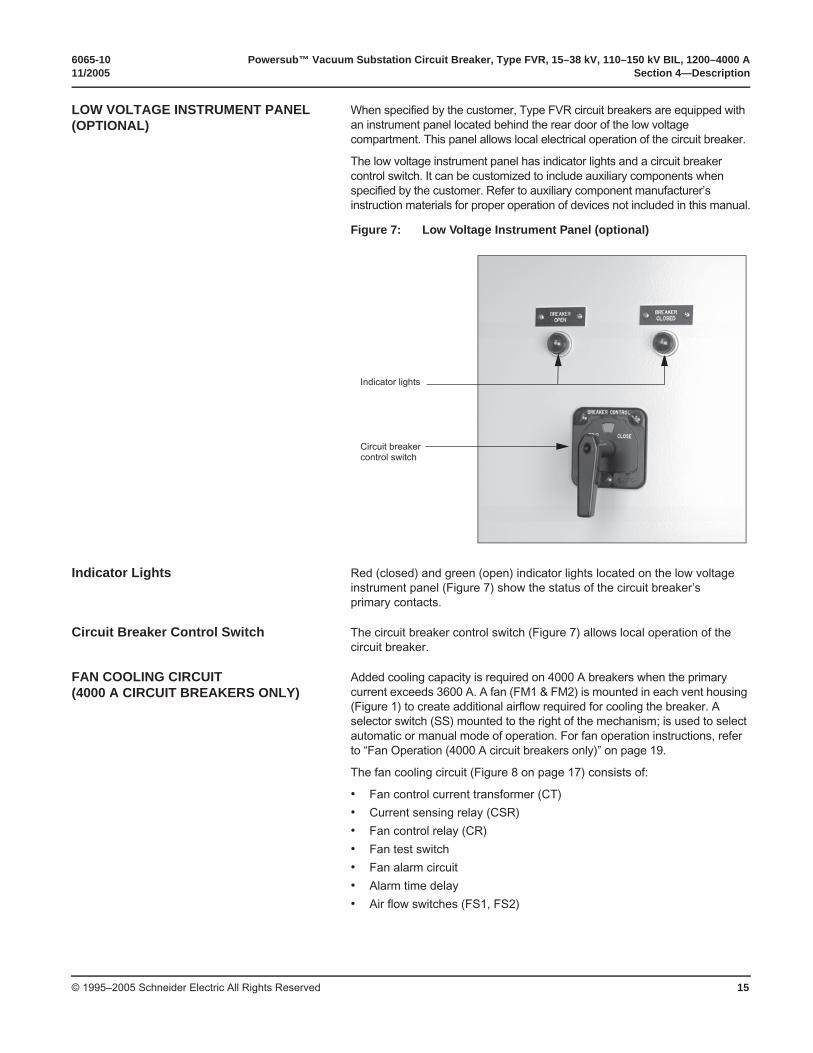
LOW VOLTAGE INSTRUMENT PANEL (OPTIONAL)
When specified by the customer, Type FVR circuit breakers are equipped with an instrument panel located behind the rear door of the low voltage compartment. This panel allows local electrical operation of the circuit breaker.
The low voltage instrument panel has indicator lights and a circuit breaker control switch. It can be customized to include auxiliary components when specified by the customer. Refer to auxiliary component manufacturer’s instruction materials for proper operation of devices not included in this manual.
Indicator Lights Red (closed) and green (open) indicator lights located on the low voltage instrument panel (Figure 7) show the status of the circuit breaker’s primary contacts.
Circuit Breaker Control Switch The circuit breaker control switch (Figure 7) allows local operation of the circuit breaker.
FAN COOLING CIRCUIT (4000 A CIRCUIT BREAKERS ONLY)
Added cooling capacity is required on 4000 A breakers when the primary current exceeds 3600 A. A fan (FM1 & FM2) is mounted in each vent housing (Figure 1) to create additional airflow required for cooling the breaker. A selector switch (SS) mounted to the right of the mechanism; is used to select automatic or manual mode of operation. For fan operation instructions, refer to “Fan Operation (4000 A circuit breakers only)” on page 19.
The fan cooling circuit (Figure 8 on page 17) consists of:
• Fan control current transformer (CT)
• Current sensing relay (CSR)
• Fan control relay (CR)
• Fan test switch
• Fan alarm circuit
• Alarm time delay
• Air flow switches (FS1, FS2)
Figure 7: Low Voltage Instrument Panel (optional)
Indicator lights
Circuit breakercontrol switch
Powersub™ Vacuum Substation Circuit Breaker, Type FVR, 15–38 kV, 110–150 kV BIL, 1200–4000 A 6065-10Section 4—Description 11/2005
© 1995–2005 Schneider Electric All Rights Reserved16
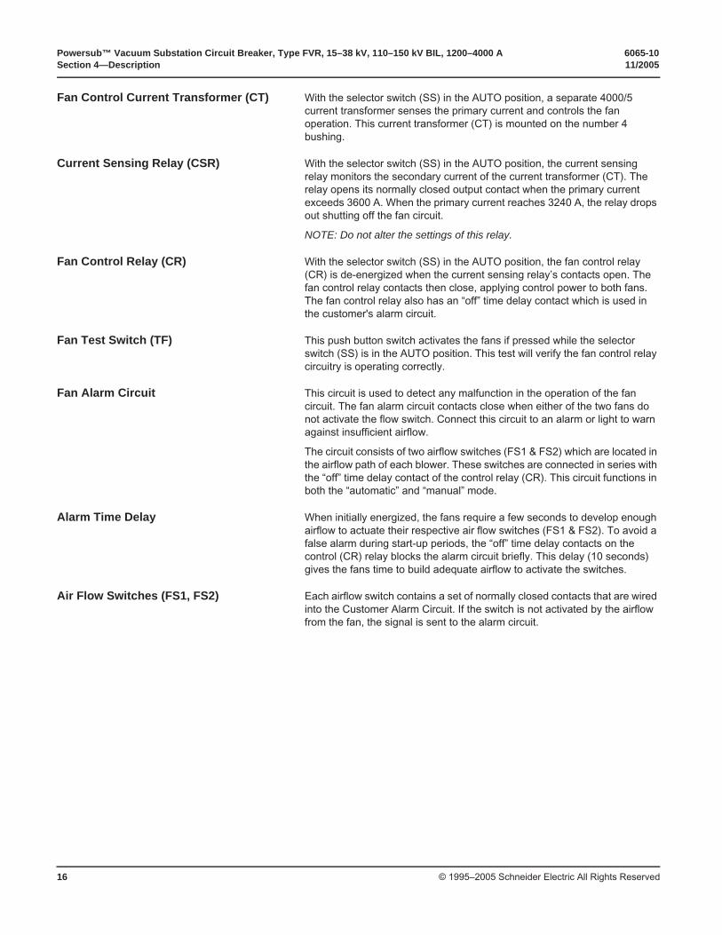
Fan Control Current Transformer (CT) With the selector switch (SS) in the AUTO position, a separate 4000/5 current transformer senses the primary current and controls the fan operation. This current transformer (CT) is mounted on the number 4 bushing.
Current Sensing Relay (CSR) With the selector switch (SS) in the AUTO position, the current sensing relay monitors the secondary current of the current transformer (CT). The relay opens its normally closed output contact when the primary current exceeds 3600 A. When the primary current reaches 3240 A, the relay drops out shutting off the fan circuit.
NOTE: Do not alter the settings of this relay.
Fan Control Relay (CR) With the selector switch (SS) in the AUTO position, the fan control relay (CR) is de-energized when the current sensing relay’s contacts open. The fan control relay contacts then close, applying control power to both fans. The fan control relay also has an “off” time delay contact which is used in the customer's alarm circuit.
Fan Test Switch (TF) This push button switch activates the fans if pressed while the selector switch (SS) is in the AUTO position. This test will verify the fan control relay circuitry is operating correctly.
Fan Alarm Circuit This circuit is used to detect any malfunction in the operation of the fan circuit. The fan alarm circuit contacts close when either of the two fans do not activate the flow switch. Connect this circuit to an alarm or light to warn against insufficient airflow.
The circuit consists of two airflow switches (FS1 & FS2) which are located in the airflow path of each blower. These switches are connected in series with the “off” time delay contact of the control relay (CR). This circuit functions in both the “automatic” and “manual” mode.
Alarm Time Delay When initially energized, the fans require a few seconds to develop enough airflow to actuate their respective air flow switches (FS1 & FS2). To avoid a false alarm during start-up periods, the “off” time delay contacts on the control (CR) relay blocks the alarm circuit briefly. This delay (10 seconds) gives the fans time to build adequate airflow to activate the switches.
Air Flow Switches (FS1, FS2) Each airflow switch contains a set of normally closed contacts that are wired into the Customer Alarm Circuit. If the switch is not activated by the airflow from the fan, the signal is sent to the alarm circuit.
6065-10 Powersub™ Vacuum Substation Circuit Breaker, Type FVR, 15–38 kV, 110–150 kV BIL, 1200–4000 A11/2005 Section 4—Description
© 1995–2005 Schneider Electric All Rights Reserved 17
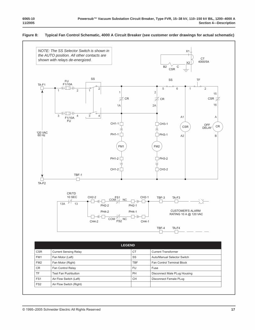
Figure 8: Typical Fan Control Schematic, 4000 A Circuit Breaker (see customer order drawings for actual schematic)
21
43
21
43
165 21
A1 A
2
1A 2A
BA2
15
16
TA-F2
TA-F1
CT4000/5A
X1
CSRCB2
X2
13A 13NC
NC
COM
COM
OFFDELAY
120 VAC60 Hz
FM1 FM2
CR
CRCR
CSR
CSR
PH1-1 PH3-1
CH1-1 CH3-1
TBF-1
CH1-2
CH2-2
PH2-1PH2-2
CH2-1
CH4-2
PH4-1PH4-2
CH4-1
CH3-2
PH1-2 PH3-2
SS TFSSFU
FU
F1/10A
F1/10A
CUSTOMER'S ALARMRATING 10 A @ 120 VAC
TA-F3
TA-F4
TBF-3
FS2
FS110 SECCR/TD
TBF-4
LEGEND
CSR Current Sensing Relay CT Current Transformer
FM1 Fan Motor (Left) SS Auto/Manual Selector Switch
FM2 Fan Motor (Right) TBF Fan Control Terminal Block
CR Fan Control Relay FU Fuse
TF Test Fan Pushbutton PH Disconnect Male PLug Housing
FS1 Air Flow Switch (Left) CH Disconnect Female PLug
FS2 Air Flow Switch (Right)
NOTE: The SS Selector Switch is shown in the AUTO position. All other contacts are shown with relays de-energized.
Powersub™ Vacuum Substation Circuit Breaker, Type FVR, 15–38 kV, 110–150 kV BIL, 1200–4000 A 6065-10Section 5—Operation 11/2005
© 1995–2005 Schneider Electric All Rights Reserved18
SECTION 5—OPERATION
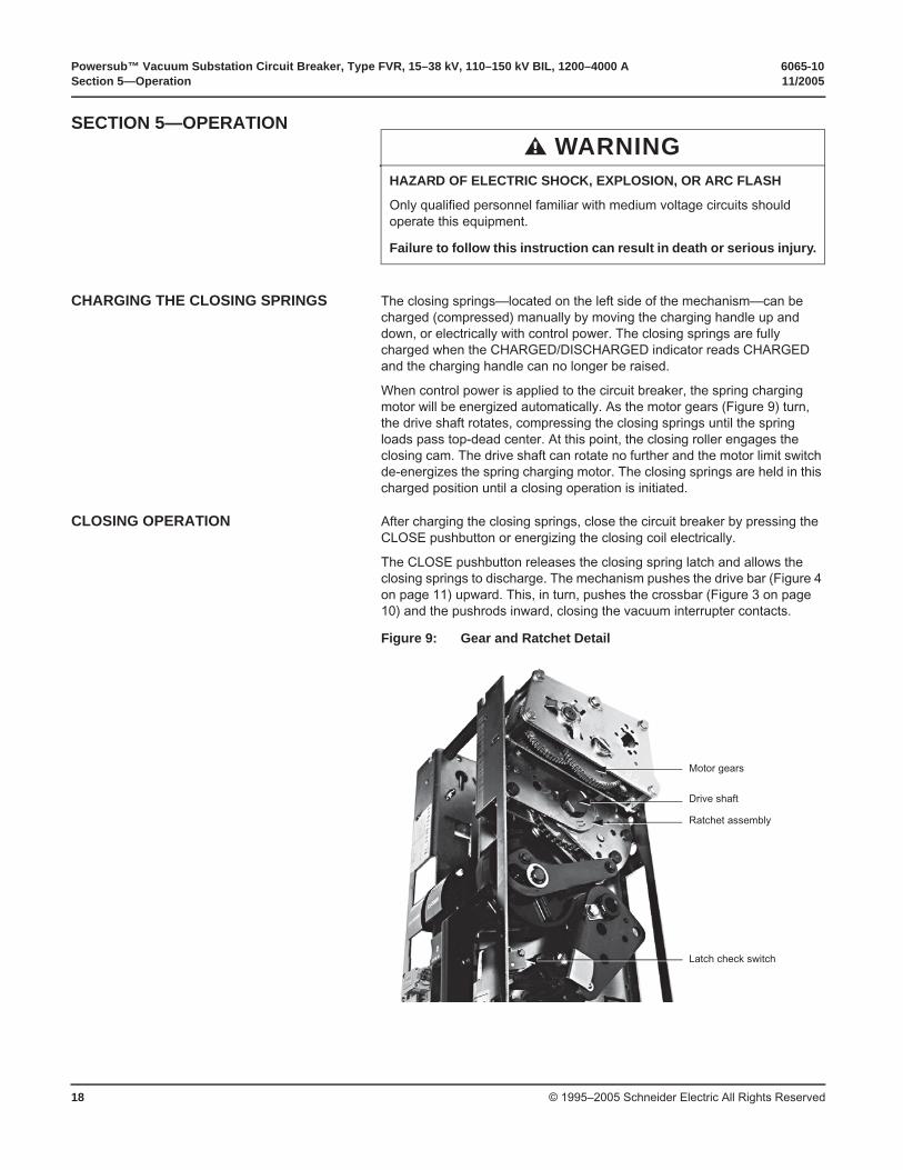
CHARGING THE CLOSING SPRINGS The closing springs—located on the left side of the mechanism—can be charged (compressed) manually by moving the charging handle up and down, or electrically with control power. The closing springs are fully charged when the CHARGED/DISCHARGED indicator reads CHARGED and the charging handle can no longer be raised.
When control power is applied to the circuit breaker, the spring charging motor will be energized automatically. As the motor gears (Figure 9) turn, the drive shaft rotates, compressing the closing springs until the spring loads pass top-dead center. At this point, the closing roller engages the closing cam. The drive shaft can rotate no further and the motor limit switch de-energizes the spring charging motor. The closing springs are held in this charged position until a closing operation is initiated.
CLOSING OPERATION After charging the closing springs, close the circuit breaker by pressing the CLOSE pushbutton or energizing the closing coil electrically.
The CLOSE pushbutton releases the closing spring latch and allows the closing springs to discharge. The mechanism pushes the drive bar (Figure 4 on page 11) upward. This, in turn, pushes the crossbar (Figure 3 on page 10) and the pushrods inward, closing the vacuum interrupter contacts.
WARNINGHAZARD OF ELECTRIC SHOCK, EXPLOSION, OR ARC FLASH
Only qualified personnel familiar with medium voltage circuits should operate this equipment.
Failure to follow this instruction can result in death or serious injury.
Figure 9: Gear and Ratchet Detail
Motor gears
Drive shaft
Ratchet assembly
Latch check switch
6065-10 Powersub™ Vacuum Substation Circuit Breaker, Type FVR, 15–38 kV, 110–150 kV BIL, 1200–4000 A11/2005 Section 5—Operation
© 1995–2005 Schneider Electric All Rights Reserved 19
OPENING OPERATION The opening springs become charged (or compressed) automatically when the circuit breaker is in the closed position. If the OPEN pushbutton is pressed or the trip coil is energized, the mechanism releases the opening latch and allows the opening springs to discharge. The opening springs pull the crossbar outward, opening the vacuum interrupter contacts. An opening operation can be initiated manually or electrically.
Manual Trip Operation The circuit breaker can be opened (tripped) manually either by pulling the external manual trip knob (Figure 1 on page 9), or by pushing the OPEN pushbutton located on the operating mechanism. The external manual trip knob allows the circuit breaker to be tripped manually without requiring entry through the low voltage compartment door.
Manual Trip Reset Switch (69 Switch)
When a trip operation is performed using the manual trip knob, the 69 switch opens, disabling the closing circuit (Figure 6 on page 14). The 69 switch, located directly under the operating mechanism (Figure 4 on page 11), must be manually reset before an electrical closing operation can occur. To reset the manual trip reset switch, follow the steps below:
1. Turn off all power to the circuit breaker.
2. Reset the manual trip reset switch by moving the toggle switch upwards.
3. Reinstall all doors and covers before turning on power to the equipment.
4. Reapply power to the circuit breaker.
Electrical Trip Operation The circuit breaker can be opened (tripped) electrically by operating the breaker control switch located on the low voltage instrument door (Figure 7 on page 15).
FAN OPERATION (4000 A CIRCUIT BREAKERS ONLY)
The fan circuit for 4000 A circuit breakers can be operated either automatically or manually. See pages 15–17 for a detailed description of the fan cooling circuit.
Automatic Operation With the selector switch (SS) in the AUTO position, the fans turn on automatically when the primary current exceeds 3600 A. The fans shut off when the primary current drops below 3240 A. To minimize fan wear, operate the fan controls in the automatic mode.
Manual Operation If there is a problem with the automatic controls, the selector switch (SS) may be placed in the “manual” position. This position will connect the control power directly to the fans. The fans operate continuously in the manual mode.
DANGERHAZARD OF ELECTRIC SHOCK, EXPLOSION, OR ARC FLASH
• Turn off all the power supplying this equipment before working on or inside it.
• Apply appropriate personal protective equipment (PPE) and follow safe electrical work practices. See NFPA 70E.
• Replace all devices, doors, and covers before turning on the power to this equipment.
Failure to follow these instructions will result in death or serious injury.
Powersub™ Vacuum Substation Circuit Breaker, Type FVR, 15–38 kV, 110–150 kV BIL, 1200–4000 A 6065-10Section 6—Installation 11/2005
© 1995–2005 Schneider Electric All Rights Reserved20
SECTION 6—INSTALLATION
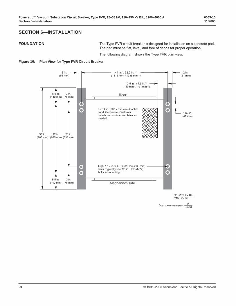
FOUNDATION The Type FVR circuit breaker is designed for installation on a concrete pad. The pad must be flat, level, and free of debris for proper operation.
The following diagram shows the Type FVR plan view:
Figure 10: Plan View for Type FVR Circuit Breaker
Dual measurements in.(mm)
44 in.* / 52.5 in. **(1118 mm* / 1335 mm**)
3.5 in.* / 7.5 in.**(89 mm* / 191 mm**)
2 in.(51 mm)
1.62 in.(41 mm)
8 x 14 in. (203 x 356 mm) Control conduit entrance. Customer installs cutouts in coverplates as needed.
Eight 1.12 in. x 1.5 in. (28 mm x 38 mm) slots. Typically use 7/8 in. UNC (M22) bolts for mounting.
Rear
Mechanism side
*110/125 kV BIL**150 kV BIL
3 in.(76 mm)
3 in.(76 mm)
2 in.(51 mm)
5.5 in.(140 mm)
21 in.(533 mm)
5.5 in.(140 mm)
27 in.(685 mm)
38 in.(965 mm)
6065-10 Powersub™ Vacuum Substation Circuit Breaker, Type FVR, 15–38 kV, 110–150 kV BIL, 1200–4000 A11/2005 Section 6—Installation
© 1995–2005 Schneider Electric All Rights Reserved 21
LIFTING THE CIRCUIT BREAKER Lifting eyes (Figure 1 on page 9) are provided on the roof of the Type FVR circuit breaker for lifting by crane. No spreader bars are required. Handle the equipment with care.
If lifting the circuit breaker by forklift, place the forklift forks underneath the low voltage compartment (Figure 1 on page 9) and secure the circuit breaker to the forklift with a strap. The floor of the low voltage compartment is reinforced to support the weight of the circuit breaker. Do not lift by the side vent housings or any other protrusions. If another handling method is necessary, contact Schneider Electric to make special preparations.
GROUNDING Connect the circuit breaker ground pads (Figure 1 on page 9) to the substation grounding grid. Use the ground pad hardware provided.
INITIAL CIRCUIT BREAKER PREPARATION
WARNINGTOP HEAVY LOAD
If lifting the circuit breaker by forklift, stabilize the circuit breaker with a safety strap to reduce the possibility of tipping.
Failure to follow this instruction can result in death or serious injury.
CAUTIONDO NOT LIFT CIRCUIT BREAKER BY SIDE VENT HOUSINGS
Damaged vent housings can constrict proper air flow and expose interior of high voltage compartment to weather.
Failure to follow this instruction can result in equipment damage.
DANGERHAZARD OF ELECTRIC SHOCK, EXPLOSION, OR ARC FLASH
• This equipment must be installed and serviced only by qualified personnel.
• Apply appropriate personal protective equipment (PPE) and follow safe electrical work practices. See NFPA 70E.
• Turn off all the power supplying this equipment before working on or inside it.
• Always use a properly rated voltage sensing device to confirm that the power is off.
• Isolate and ground both the line and the load side of the circuit breaker.
• Make sure the breaker is in the OPEN position before inspecting this equipment or connecting the circuit breaker to your system.
• Replace all devices, doors, and covers before turning on the power to this equipment.
Failure to follow these instructions will result in death or serious injury.
Powersub™ Vacuum Substation Circuit Breaker, Type FVR, 15–38 kV, 110–150 kV BIL, 1200–4000 A 6065-10Section 6—Installation 11/2005
© 1995–2005 Schneider Electric All Rights Reserved22
Before connecting the Type FVR vacuum circuit breaker to the primary circuit, prepare it for operation.
1. Check the indicators to verify that the circuit breaker is in the open position with all springs discharged. If it is not in this position, press the OPEN pushbutton, the CLOSE pushbutton, and then the OPEN pushbutton (Figure 4 on page 11).
NOTE: The circuit breaker is normally shipped in the closed position.
2. Examine the entire circuit breaker for damage, dirt, and moisture.
3. Use a clean, dry cloth to remove dirt and moisture that may have collected on the insulating parts.
4. Cycle the circuit breaker manually several times, checking for proper operation. To do so, move the charging handle (Figure 4 on page 11) up and down until the closing springs are fully charged. A full charge is indicated when the charging handle can no longer be raised and the CHARGED-DISCHARGED indicator reads “charged”. Close the circuit breaker by pressing the CLOSE pushbutton, and then open it by pressing the OPEN pushbutton.
5. Verify that the heater thermostat (Figure 5 on page 13) is set at 75 °F (24 °C).
6. Inspect and remove all loose parts, tools, and miscellaneous construction items left inside the circuit breaker before the power is energized.
7. Reinstall all doors and covers and fasten them securely. For arc-resistant protection, all doors must be closed and covers installed.
ARC-RESISTANCE FEATURE All Type FVR circuit breakers, except those rated at or above 3000 A, have an arc-resistance enclosure. For proper operation of this feature, ensure the following requirements are met:
• High voltage panels are installed and mounting bolts are tightened.
• Low voltage doors are shut with all door handles latched closed.
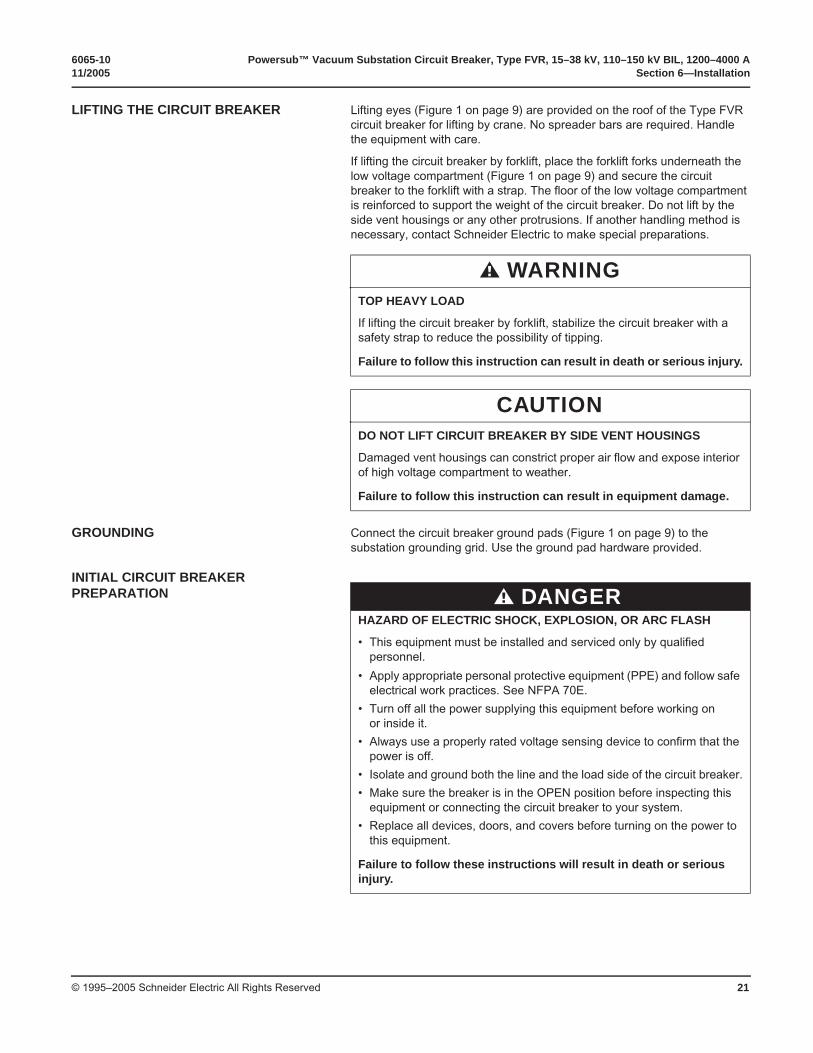
• Glass polyester vent covers (Figure 11) are in place with the mounting springs relaxed. The springs offer the required spacing for ventilation and also allow the cover to close the opening should an arc occur.
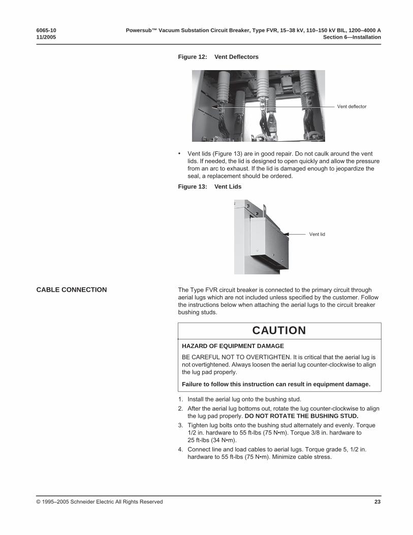
• Vent deflectors (Figure 12 on page 23) are installed and in good repair. They fold into the vent housing, forcing the exhaust through the vent lids (Figure 13 on page 23) if an arc occurs. If these parts are removed or broken during shipment, a replacement should be ordered.
Figure 11: Vent Covers
Vent covers
6065-10 Powersub™ Vacuum Substation Circuit Breaker, Type FVR, 15–38 kV, 110–150 kV BIL, 1200–4000 A11/2005 Section 6—Installation
© 1995–2005 Schneider Electric All Rights Reserved 23
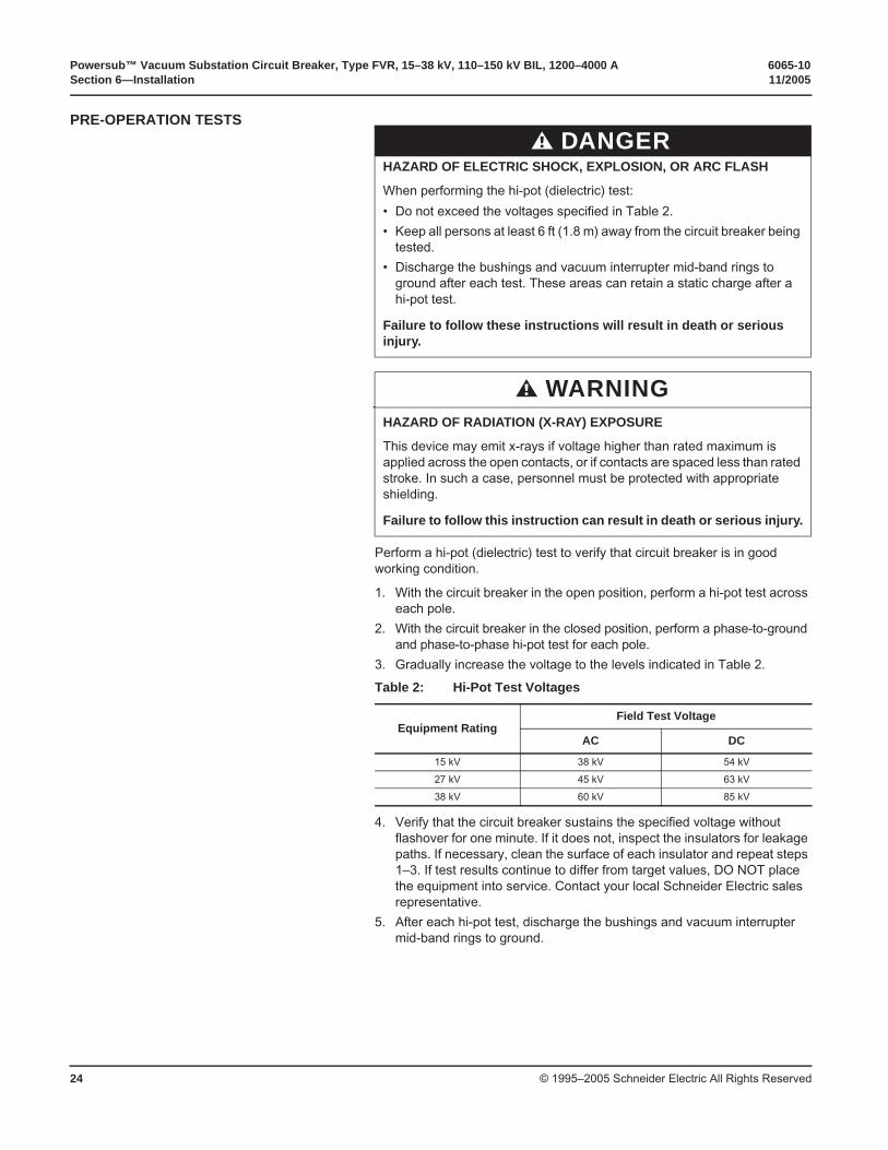
• Vent lids (Figure 13) are in good repair. Do not caulk around the vent lids. If needed, the lid is designed to open quickly and allow the pressure from an arc to exhaust. If the lid is damaged enough to jeopardize the seal, a replacement should be ordered.
CABLE CONNECTION The Type FVR circuit breaker is connected to the primary circuit through aerial lugs which are not included unless specified by the customer. Follow the instructions below when attaching the aerial lugs to the circuit breaker bushing studs.
1. Install the aerial lug onto the bushing stud.
2. After the aerial lug bottoms out, rotate the lug counter-clockwise to align the lug pad properly. DO NOT ROTATE THE BUSHING STUD.
3. Tighten lug bolts onto the bushing stud alternately and evenly. Torque 1/2 in. hardware to 55 ft-lbs (75 N•m). Torque 3/8 in. hardware to 25 ft-lbs (34 N•m).
4. Connect line and load cables to aerial lugs. Torque grade 5, 1/2 in. hardware to 55 ft-lbs (75 N•m). Minimize cable stress.
Figure 12: Vent Deflectors
Figure 13: Vent Lids
Vent deflector
Vent lid
CAUTIONHAZARD OF EQUIPMENT DAMAGE
BE CAREFUL NOT TO OVERTIGHTEN. It is critical that the aerial lug is not overtightened. Always loosen the aerial lug counter-clockwise to align the lug pad properly.
Failure to follow this instruction can result in equipment damage.
Powersub™ Vacuum Substation Circuit Breaker, Type FVR, 15–38 kV, 110–150 kV BIL, 1200–4000 A 6065-10Section 6—Installation 11/2005
© 1995–2005 Schneider Electric All Rights Reserved24
PRE-OPERATION TESTS
Perform a hi-pot (dielectric) test to verify that circuit breaker is in good working condition.
1. With the circuit breaker in the open position, perform a hi-pot test across each pole.
2. With the circuit breaker in the closed position, perform a phase-to-ground and phase-to-phase hi-pot test for each pole.
3. Gradually increase the voltage to the levels indicated in Table 2.
4. Verify that the circuit breaker sustains the specified voltage without flashover for one minute. If it does not, inspect the insulators for leakage paths. If necessary, clean the surface of each insulator and repeat steps 1–3. If test results continue to differ from target values, DO NOT place the equipment into service. Contact your local Schneider Electric sales representative.
5. After each hi-pot test, discharge the bushings and vacuum interrupter mid-band rings to ground.
DANGERHAZARD OF ELECTRIC SHOCK, EXPLOSION, OR ARC FLASH
When performing the hi-pot (dielectric) test:
• Do not exceed the voltages specified in Table 2.
• Keep all persons at least 6 ft (1.8 m) away from the circuit breaker being tested.
• Discharge the bushings and vacuum interrupter mid-band rings to ground after each test. These areas can retain a static charge after a hi-pot test.
Failure to follow these instructions will result in death or serious injury.
WARNINGHAZARD OF RADIATION (X-RAY) EXPOSURE
This device may emit x-rays if voltage higher than rated maximum is applied across the open contacts, or if contacts are spaced less than rated stroke. In such a case, personnel must be protected with appropriate shielding.
Failure to follow this instruction can result in death or serious injury.
Table 2: Hi-Pot Test Voltages
Equipment RatingField Test Voltage
AC DC
15 kV 38 kV 54 kV
27 kV 45 kV 63 kV
38 kV 60 kV 85 kV
6065-10 Powersub™ Vacuum Substation Circuit Breaker, Type FVR, 15–38 kV, 110–150 kV BIL, 1200–4000 A11/2005 Section 7—Maintenance
© 1995–2005 Schneider Electric All Rights Reserved 25
SECTION 7—MAINTENANCE This section contains the inspection and maintenance procedures recommended by Schneider Electric.
Because of wide variations in operating uses and environments, a maintenance schedule should be developed for the particular end use. Until a schedule is determined, inspect Type FVR circuit breakers once a year or after the number of operations shown in Table 3, whichever occurs first.
Inspect Type FVR Circuit Breakers after several (maximum of 10) full-rated fault conditions and record any contact erosion (refer to “Contact Erosion” on page 26).
GENERAL INSPECTION Visually inspect the entire circuit breaker and operating mechanism for loose parts or connections. Examine the circuit breaker for evidence of overheating or excessive dirt or moisture. If such evidence is found contact your local Schneider Electric sales representative.
DANGERHAZARD OF ELECTRIC SHOCK, EXPLOSION, OR ARC FLASH
• This equipment must be installed and serviced only by qualified personnel.
• Apply appropriate personal protective equipment (PPE) and follow safe electrical work practices. See NFPA 70E.
• Turn off all power supplying this equipment before working on or inside.
• Always use a properly rated voltage sensing device to confirm that power is off.
• Replace all devices, doors, and covers before turning on the power to this equipment.
• All maintenance must be performed in accordance with local codes and under the following conditions:
— The circuit breaker must be isolated from all power sources.
— Control voltage must be removed from the control circuits.
— The circuit breaker must be in the open position.
— All circuit breaker springs must be discharged.
• All instructions in this manual are written with the assumption that the customer has taken these measures before performing maintenance or testing.
• Open the circuit breaker and discharge all springs by pressing the OPEN and CLOSE pushbuttons in the order OPEN-CLOSE-OPEN.
• Qualified personnel should establish procedures that ensure the safety of personnel and equipment.
Failure to follow these instructions will result in death or serious injury.
Table 3: Inspection Intervals
Breaker Rating Number of Operations
15/27 kV, 1200/2000 A, 110/125 kV BIL, 25 kA 2000
27/38 kV, 1200/2000 A, 150 kV BIL, 31.5 kA 1000
15 kV, 3000/3500/4000 A,110 kV BIL, 40 kA 500
Powersub™ Vacuum Substation Circuit Breaker, Type FVR, 15–38 kV, 110–150 kV BIL, 1200–4000 A 6065-10Section 7—Maintenance 11/2005
© 1995–2005 Schneider Electric All Rights Reserved26
INSULATING SURFACES Use a clean, dry cloth to remove all dirt and moisture from the outside of the vacuum interrupters and from all insulating parts.
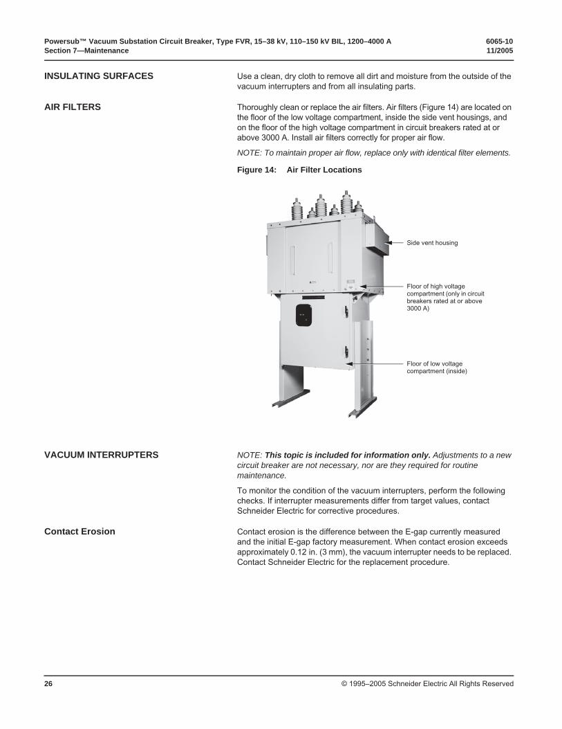
AIR FILTERS Thoroughly clean or replace the air filters. Air filters (Figure 14) are located on the floor of the low voltage compartment, inside the side vent housings, and on the floor of the high voltage compartment in circuit breakers rated at or above 3000 A. Install air filters correctly for proper air flow.
NOTE: To maintain proper air flow, replace only with identical filter elements.
VACUUM INTERRUPTERS NOTE: This topic is included for information only. Adjustments to a new circuit breaker are not necessary, nor are they required for routine maintenance.
To monitor the condition of the vacuum interrupters, perform the following checks. If interrupter measurements differ from target values, contact Schneider Electric for corrective procedures.
Contact Erosion Contact erosion is the difference between the E-gap currently measured and the initial E-gap factory measurement. When contact erosion exceeds approximately 0.12 in. (3 mm), the vacuum interrupter needs to be replaced. Contact Schneider Electric for the replacement procedure.
Figure 14: Air Filter Locations
Side vent housing
Floor of low voltage compartment (inside)
Floor of high voltage compartment (only in circuit breakers rated at or above 3000 A)
6065-10 Powersub™ Vacuum Substation Circuit Breaker, Type FVR, 15–38 kV, 110–150 kV BIL, 1200–4000 A11/2005 Section 7—Maintenance
© 1995–2005 Schneider Electric All Rights Reserved 27
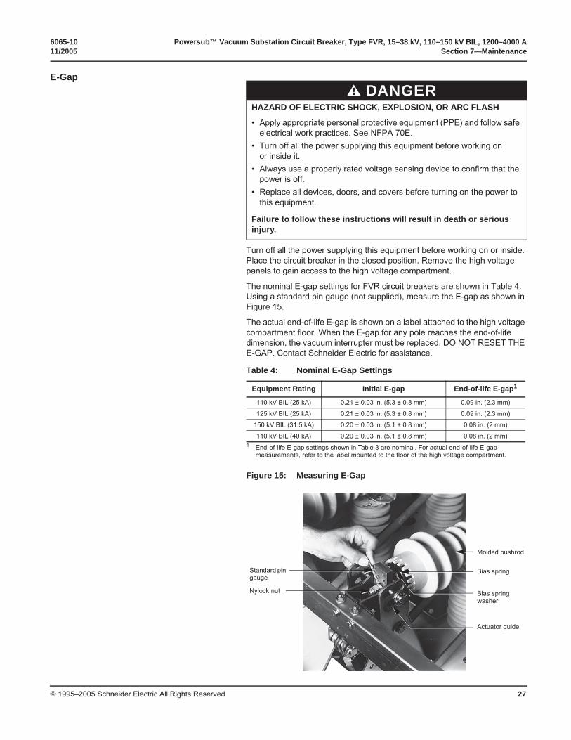
E-Gap
Turn off all the power supplying this equipment before working on or inside. Place the circuit breaker in the closed position. Remove the high voltage panels to gain access to the high voltage compartment.
The nominal E-gap settings for FVR circuit breakers are shown in Table 4. Using a standard pin gauge (not supplied), measure the E-gap as shown in Figure 15.
The actual end-of-life E-gap is shown on a label attached to the high voltage compartment floor. When the E-gap for any pole reaches the end-of-life dimension, the vacuum interrupter must be replaced. DO NOT RESET THE E-GAP. Contact Schneider Electric for assistance.
DANGERHAZARD OF ELECTRIC SHOCK, EXPLOSION, OR ARC FLASH
• Apply appropriate personal protective equipment (PPE) and follow safe electrical work practices. See NFPA 70E.
• Turn off all the power supplying this equipment before working on or inside it.
• Always use a properly rated voltage sensing device to confirm that the power is off.
• Replace all devices, doors, and covers before turning on the power to this equipment.
Failure to follow these instructions will result in death or serious injury.
Table 4: Nominal E-Gap Settings
Equipment Rating Initial E-gap End-of-life E-gap1
1 End-of-life E-gap settings shown in Table 3 are nominal. For actual end-of-life E-gap measurements, refer to the label mounted to the floor of the high voltage compartment.
110 kV BIL (25 kA) 0.21 ± 0.03 in. (5.3 ± 0.8 mm) 0.09 in. (2.3 mm)
125 kV BIL (25 kA) 0.21 ± 0.03 in. (5.3 ± 0.8 mm) 0.09 in. (2.3 mm)
150 kV BIL (31.5 kA) 0.20 ± 0.03 in. (5.1 ± 0.8 mm) 0.08 in. (2 mm)
110 kV BIL (40 kA) 0.20 ± 0.03 in. (5.1 ± 0.8 mm) 0.08 in. (2 mm)
Figure 15: Measuring E-Gap
Molded pushrod
Nylock nut
Bias spring
Bias spring washer
Actuator guide
Standard pin gauge
Powersub™ Vacuum Substation Circuit Breaker, Type FVR, 15–38 kV, 110–150 kV BIL, 1200–4000 A 6065-10Section 7—Maintenance 11/2005
© 1995–2005 Schneider Electric All Rights Reserved28
Contact Gap The contact gap dimension is recorded on the label mounted to the floor of the high voltage compartment and is provided for reference purposes only.
Hi-Pot (Dielectric) Test Hi-pot (high potential) tests must be performed as part of a series of pre-operational tests (refer to “Pre-Operation Tests” on page 24), regular maintenance, and as a method of determining adequacy against breakdown of insulating materials and spacings under normal conditions. Consistent unacceptable test results may indicate a loss of vacuum. Contact Schneider Electric for technical assistance.
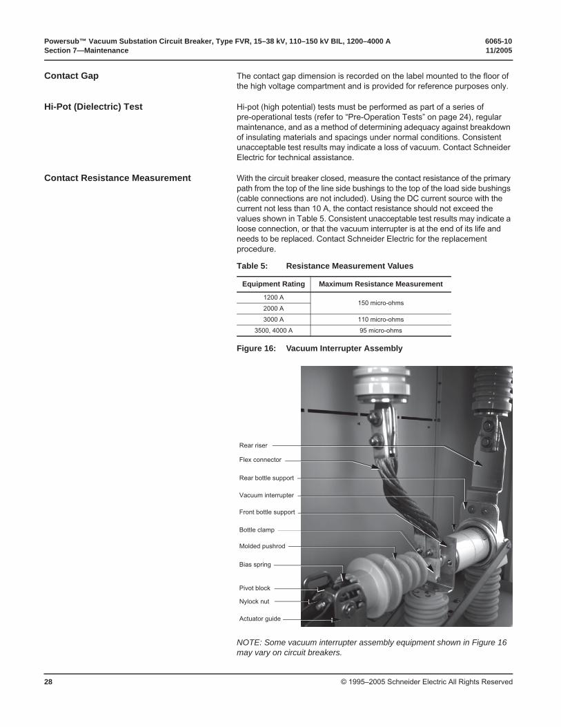
Contact Resistance Measurement With the circuit breaker closed, measure the contact resistance of the primary path from the top of the line side bushings to the top of the load side bushings (cable connections are not included). Using the DC current source with the current not less than 10 A, the contact resistance should not exceed the values shown in Table 5. Consistent unacceptable test results may indicate a loose connection, or that the vacuum interrupter is at the end of its life and needs to be replaced. Contact Schneider Electric for the replacement procedure.
NOTE: Some vacuum interrupter assembly equipment shown in Figure 16 may vary on circuit breakers.
Table 5: Resistance Measurement Values
Equipment Rating Maximum Resistance Measurement
1200 A150 micro-ohms
2000 A
3000 A 110 micro-ohms
3500, 4000 A 95 micro-ohms
Figure 16: Vacuum Interrupter Assembly
Rear riser
Pivot block
Nylock nut
Flex connector
Rear bottle support
Vacuum interrupter
Front bottle support
Bottle clamp
Molded pushrod
Bias spring
Actuator guide
6065-10 Powersub™ Vacuum Substation Circuit Breaker, Type FVR, 15–38 kV, 110–150 kV BIL, 1200–4000 A11/2005 Section 7—Maintenance
© 1995–2005 Schneider Electric All Rights Reserved 29
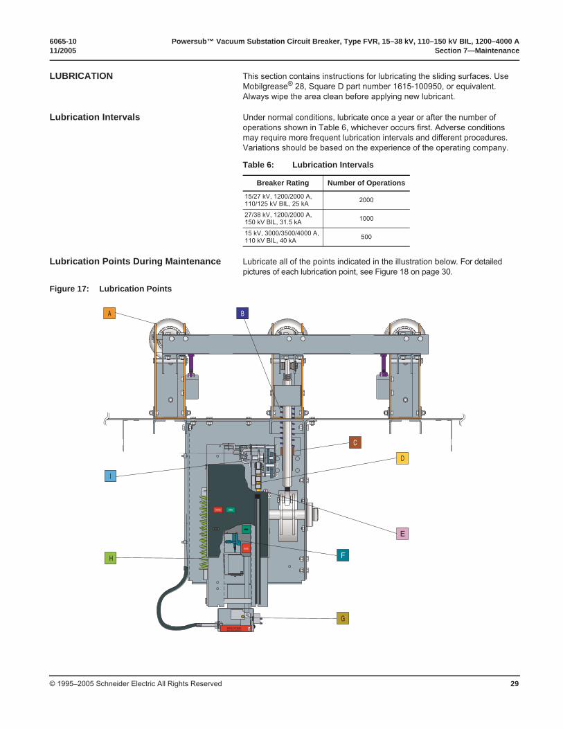
LUBRICATION This section contains instructions for lubricating the sliding surfaces. Use Mobilgrease® 28, Square D part number 1615-100950, or equivalent. Always wipe the area clean before applying new lubricant.
Lubrication Intervals Under normal conditions, lubricate once a year or after the number of operations shown in Table 6, whichever occurs first. Adverse conditions may require more frequent lubrication intervals and different procedures. Variations should be based on the experience of the operating company.
Lubrication Points During Maintenance Lubricate all of the points indicated in the illustration below. For detailed pictures of each lubrication point, see Figure 18 on page 30.
Table 6: Lubrication Intervals
Breaker Rating Number of Operations
15/27 kV, 1200/2000 A, 110/125 kV BIL, 25 kA 2000
27/38 kV, 1200/2000 A, 150 kV BIL, 31.5 kA 1000
15 kV, 3000/3500/4000 A,110 kV BIL, 40 kA 500
Figure 17: Lubrication Points
BA
H
I
E
F
G
C
D
CHARGED
OPENOPEN
CLOSE
OPEN
0 0 0 5 0
MANUAL TRIP RESETMOVE TOGGLE SWITCH UP
Powersub™ Vacuum Substation Circuit Breaker, Type FVR, 15–38 kV, 110–150 kV BIL, 1200–4000 A 6065-10Section 7—Maintenance 11/2005
© 1995–2005 Schneider Electric All Rights Reserved30
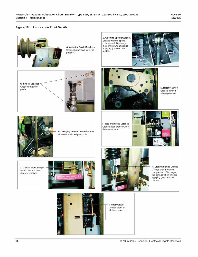
Figure 18: Lubrication Point Details
A. Actuator Guide BracketsGrease both travel slots (all phases).
I. Motor GearsGrease teeth on all three gears.
D. Ratchet WheelGrease all teeth where possible.
E. Charging Lever Connection ArmGrease the slotted pivot hole.
F. Trip and Close LatchesGrease both latches where the cams touch.
G. Manual Trip LinkageGrease rod and both interlock brackets.
C. Shock BracketGrease both pivot points.
H. Closing Spring GuidesGrease with the spring compressed. Discharge the springs when finished applying grease to the guides.
B. Opening Spring GuidesGrease with the spring compressed. Discharge the springs when finished applying grease to the guides.
6065-10 Powersub™ Vacuum Substation Circuit Breaker, Type FVR, 15–38 kV, 110–150 kV BIL, 1200–4000 A11/2005 Section 8—Replacement Parts
© 1995–2005 Schneider Electric All Rights Reserved 31
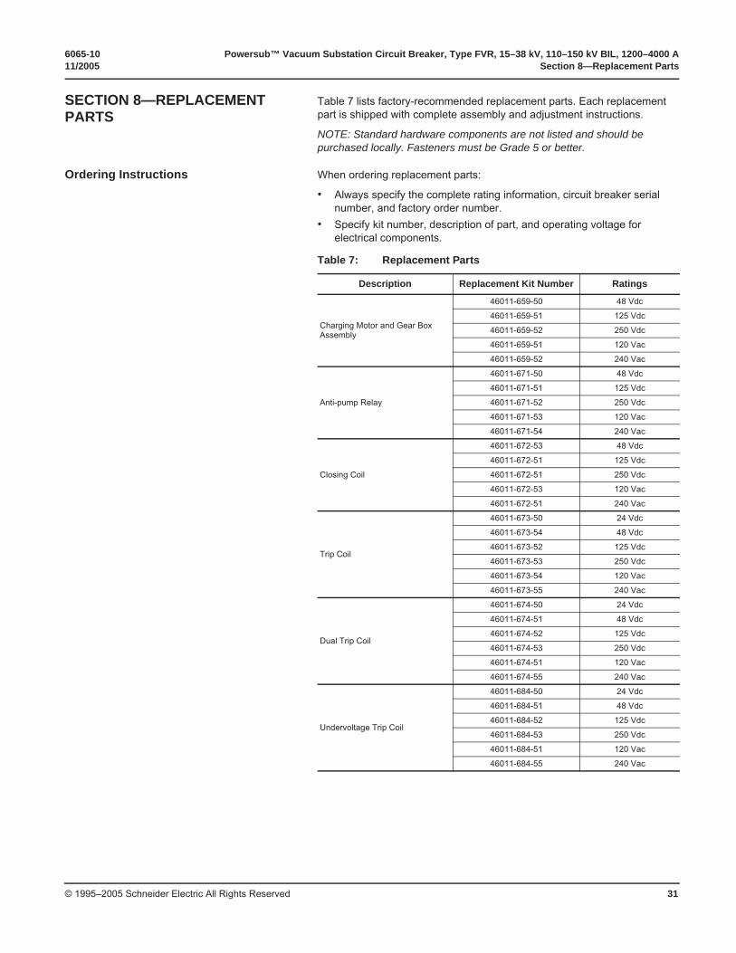
SECTION 8—REPLACEMENT PARTS
Table 7 lists factory-recommended replacement parts. Each replacement part is shipped with complete assembly and adjustment instructions.
NOTE: Standard hardware components are not listed and should be purchased locally. Fasteners must be Grade 5 or better.
Ordering Instructions When ordering replacement parts:
• Always specify the complete rating information, circuit breaker serial number, and factory order number.
• Specify kit number, description of part, and operating voltage for electrical components.
Table 7: Replacement Parts
Description Replacement Kit Number Ratings
Charging Motor and Gear Box Assembly
46011-659-50 48 Vdc
46011-659-51 125 Vdc
46011-659-52 250 Vdc
46011-659-51 120 Vac
46011-659-52 240 Vac
Anti-pump Relay
46011-671-50 48 Vdc
46011-671-51 125 Vdc
46011-671-52 250 Vdc
46011-671-53 120 Vac
46011-671-54 240 Vac
Closing Coil
46011-672-53 48 Vdc
46011-672-51 125 Vdc
46011-672-51 250 Vdc
46011-672-53 120 Vac
46011-672-51 240 Vac
Trip Coil
46011-673-50 24 Vdc
46011-673-54 48 Vdc
46011-673-52 125 Vdc
46011-673-53 250 Vdc
46011-673-54 120 Vac
46011-673-55 240 Vac
Dual Trip Coil
46011-674-50 24 Vdc
46011-674-51 48 Vdc
46011-674-52 125 Vdc
46011-674-53 250 Vdc
46011-674-51 120 Vac
46011-674-55 240 Vac
Undervoltage Trip Coil
46011-684-50 24 Vdc
46011-684-51 48 Vdc
46011-684-52 125 Vdc
46011-684-53 250 Vdc
46011-684-51 120 Vac
46011-684-55 240 Vac
Powersub™ Vacuum Substation Circuit Breaker, Type FVR, 15–38 kV, 110–150 kV BIL, 1200–4000 A 6065-10Section 8—Replacement Parts 11/2005
© 1995–2005 Schneider Electric All Rights Reserved32
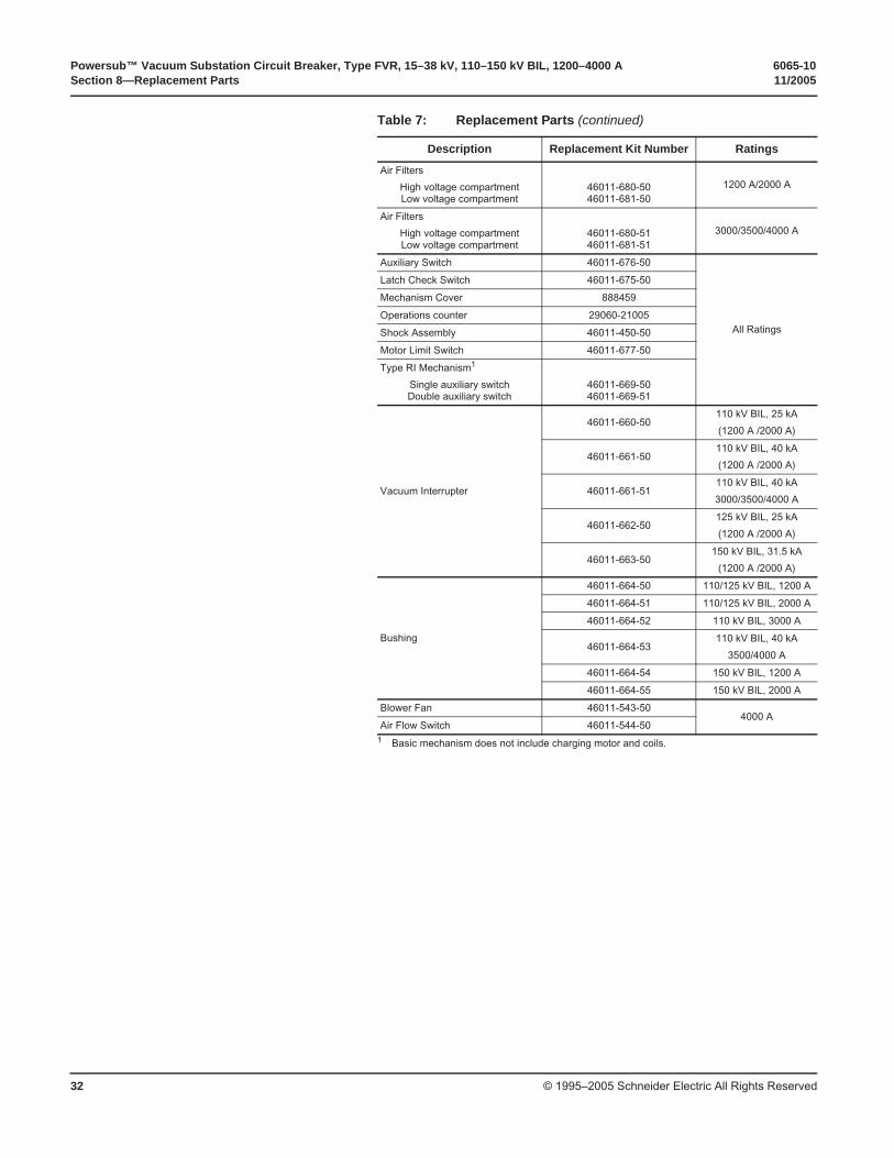
Air Filters
High voltage compartmentLow voltage compartment
46011-680-5046011-681-50
1200 A/2000 A
Air Filters
High voltage compartmentLow voltage compartment
46011-680-5146011-681-51
3000/3500/4000 A
Auxiliary Switch 46011-676-50
All Ratings
Latch Check Switch 46011-675-50
Mechanism Cover 888459
Operations counter 29060-21005
Shock Assembly 46011-450-50
Motor Limit Switch 46011-677-50
Type RI Mechanism1
Single auxiliary switchDouble auxiliary switch
46011-669-5046011-669-51
Vacuum Interrupter
46011-660-50110 kV BIL, 25 kA
(1200 A /2000 A)
46011-661-50110 kV BIL, 40 kA
(1200 A /2000 A)
46011-661-51110 kV BIL, 40 kA
3000/3500/4000 A
46011-662-50125 kV BIL, 25 kA
(1200 A /2000 A)
46011-663-50150 kV BIL, 31.5 kA
(1200 A /2000 A)
Bushing
46011-664-50 110/125 kV BIL, 1200 A
46011-664-51 110/125 kV BIL, 2000 A
46011-664-52 110 kV BIL, 3000 A
46011-664-53110 kV BIL, 40 kA
3500/4000 A
46011-664-54 150 kV BIL, 1200 A
46011-664-55 150 kV BIL, 2000 A
Blower Fan 46011-543-504000 A
Air Flow Switch 46011-544-501 Basic mechanism does not include charging motor and coils.
Table 7: Replacement Parts (continued)
Description Replacement Kit Number Ratings
6065-10 Powersub™ Vacuum Substation Circuit Breaker, Type FVR, 15–38 kV, 110–150 kV BIL, 1200–4000 A11/2005 Section 9—Maintenance Log
© 1995–2005 Schneider Electric All Rights Reserved 33
SECTION 9—MAINTENANCE LOG
DATE INITIALS ACTIONS
Powersub™ Vacuum Substation Circuit Breaker, Type FVR, 15–38 kV, 110–150 kV BIL, 1200–4000 A 6065-10Section 9—Maintenance Log 11/2005
© 1995–2005 Schneider Electric All Rights Reserved34
DATE INITIALS ACTIONS

Electrical equipment should be installed, operated, serviced, and maintained only by qualified personnel. No responsibility is assumed by Schneider Electric for any consequences arising out of the use of this material.
6065-10 © 1995–2005 Schneider Electric All Rights Reserved Replaces 6065-10 dated 06/2002.
9870 Crescent Park DriveWest Chester, OH 45069 USA1-888-SquareD (1-888-778-2733)www.us.SquareD.com
11/2005
Schneider Electric USA
Powersub™ Vacuum Substation Circuit Breaker, Type FVR, 15–38 kV, 110–150 kV BIL, 1200–4000 AInstruction Bulletin