Embed Size (px)
Citation preview

A I R C I R C U I T B R E A K E R A C B - 4 0 1 2
SPD Electrical SystemsSPD Electrical Systems
P ro d u c t D e s c r i p t i o n
With over 100 years of experience dating back to Henry
Cutter’s first “inverse time element” circuit breaker in the late
nineteenth century, L-3 SPD Electrical Systems (L-3 SPDES)
is the world’s leading supplier of innovative, shock-hardened
circuit breakers and switchgear for harsh environment
applications.
L-3 SPDES’ Navy Type ACB-4012 is a draw-out style, low-
voltage air circuit breaker that is rated for a continuous
current of 4,000 A at 500 VAC and a symmetrical interrupting
rating of 85 kARMS. The L-3 ACB-4012 is ideal for applications
where integrated control, condition based maintenance, and
power monitoring are required.
Originally a commercial design, L-3 SPDES has ruggedized
the ACB-4012 circuit breaker assembly to qualified military
specifications MIL-DTL-17587; MIL-S-901, Grade A; and MIL-
STD-167-1A, Type 1 (4 to 33 Hz) for use in harsh conditions
experienced on board navy ships. The circuit breaker is
designed for easy front access so that the unit can be
controlled and monitored safely through an access port on
the front door of a switchgear enclosure.
HIGHLIGHTS
• Replaces ACB-4010HR and ACB-4000HR circuit breakers
• Ruggedized commercial design-qualified to military specifications
• Easy front access for convenient manual control
• Sophisticated electronic protection module
• Quick and easy removal from cradle
• Closing spring charged either automatically or manually
• Breaker position and closing spring status flags
• Colored indicating lights show OPEN/CLOSED status
• Optional Electromechanical Undervoltage Lockout
AVAILABLE FEATURES
FEATURE STANDARD OPTION FIELD SELECTABLE
Electrical Closing Mechanism 3
Hold Close 3 3
Racking Mechanism Lockout (Mechanical) 3
Mechanical Racking Position Indicator 3
Secondary Disconnect Terminal Blocks (Qty. 18) 3
Operations Counter 3
Overcurrent Protection 3 3
Shunt Trip (120 V) 3
Electromechanical Undervoltage Lock Out (UVLO) 3
Status Indicating Light 3
RATINGS (Circuit Breaker and Attachments) Maximum Continuous Current (Amperes) 4,000
Continuous Current Setting (Amperes) (100 A increments) 2,000 to 4,000
Rated Maximum Volts (60 Hz) 500
Maximum Interrupting Rating - Symmetrical Short Circuit Current (Amperes) 85,000
Rated Short-Time Current Delay at 85 kA (Seconds) 0.75
Number of Phases 3
Number of Protected Poles 6 (2 per phase)
Auxiliary Switch – Number of Contacts 18 (11 ‘A’/ 7 ‘B’)
Auxiliary Switch Ratings 120VAC, 15A / 500VAC,15A
Secondary Disconnect Terminal Block 18 Amp to 20 Amp @ Current Rating 600 VAC
L-3 SPD Electrical Systems
13500 Roosevelt Boulevard
Philadelphia, PA 19116
Tel: 215-677-4900
Email: [email protected]
L-3com.com/SPDES
A I R C I R C U I T B R E A K E R A C B - 4 0 1 2
OPERATION
The main operations of the circuit breaker are as follows:
• Opening: The opening of the breaker can be initiated with or without control power applied using the red PUSH OFF push-button
• Charging: The closing springs can be charged, either automatically (when control power is applied to the charging motor) or manually (using the charging handle) after the breaker has been opened
• Closing: Once the closing springs have been charged, the breaker can be closed using the green PUSH ON push-button with or without control power applied
• Resetting a fault trip: If a protective trip occurs, the reset button on the protective device can be used to clear the fault alarm after the cause is resolved
PHYSICAL CHARACTERISTICS
ACB-4012 WIDTH HEIGHT DEPTH WEIGHT ASSEMBLY
Circuit Breaker 25.41 in. 17.64 in. 18.85 in. 315 lb. (81.56 cm) (44.8 cm) (47.9 cm)
Cradle 32.11 in. 23.20 in. 25.35 in. 422 lb. (Track Extension (44.9 cm) (58.93 cm) (64.39 cm) Raised)
Cradle Same as Same as 42.97 in 737 lb. (Track Extension Above Above (109.14 cm) Lowered with Breaker in Test or CONNECT Positions)
Maximum Overall (Breaker in Same as Same as 44.07 in. Same as DISCONNECT Above Above (111.94 cm) Above position on Track Extension)
ACB-4012 Circuit Breaker in ACB-4000HR Modified Cradle
(Track Extension Lowered)
RETROFITTING
The L-3 SPDES ACB-4012 is a form, fit, and
function replacement for the ACB-4010HR and
can also be adapted to fit into ACB-4000HR
switchboards using a modified cradle design.
The modified cradle for the ACB-4000HR is
shown below with the overall dimensions.
Approved for Release. Distribution is unlimited.
SPD Electrical SystemsSPD Electrical Systems
A I R C I R C U I T B R E A K E R A C B - 4 0 1 2
A I R C I R C U I T B R E A K E R A C B - 4 0 1 2
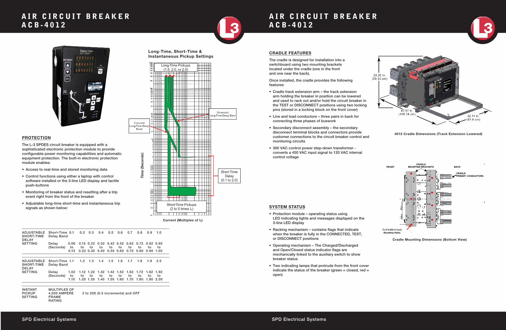
CRADLE FEATURES
The cradle is designed for installation into a switchboard using two mounting brackets located under the cradle (one in the front and one near the back). Once installed, the cradle provides the following features:
• Cradle track extension arm – the track extension arm holding the breaker in position can be lowered and used to rack out and/or hold the circuit breaker in the TEST or DISCONNECT positions using two locking pins (stored in a locking block on the front cover)
• Line and load conductors – three pairs in back for connecting three phases of buswork
• Secondary disconnect assembly – the secondary disconnect terminal blocks and connectors provide customer connections to the circuit breaker control and monitoring circuits
• 300 VAC control power step-down transformer - converts a 450 VAC input signal to 120 VAC internal control voltage
Current (Multiples of Ir)
4012 Cradle Dimensions (Track Extension Lowered)
Cradle Mounting Dimensions (Bottom View)
PROTECTION
The L-3 SPDES circuit breaker is equipped with a sophisticated electronic protection module to provide configurable power monitoring capabilities and automatic equipment protection. The built-in electronic protection module enables:
SYSTEM STATUS
• Protection module – operating status using LED indicating lights and messages displayed on the 3-line LED display
• Racking mechanism – contains flags that indicate when the breaker is fully in the CONNECTED, TEST, or DISCONNECT positions
• Operating mechanism – The Charged/Discharged and Open/Closed status indicator flags are mechanically linked to the auxiliary switch to show breaker status
• Two indicating lamps that protrude from the front cover indicate the status of the breaker (green = closed, red = open)
ADJUSTABLE Short-Time 0.1 0.2 0.3 0.4 0.5 0.6 0.7 0.8 0.9 1.0 SHORT-TIME Delay Band DELAY SETTING Delay 0.06 0.15 0.22 0.32 0.42 0.52 0.62 0.72 0.82 0.92 (Seconds) to to to to to to to to to to 0.13 0.22 0.30 0.40 0.50 0.60 0.70 0.80 0.90 1.00
INSTANT MULTIPLES OF PICKUP 4,000 AMPERE 2 to 20X (0.5 increments) and OFF SETTING FRAME RATING
ADJUSTABLE Short-Time 1.1 1.2 1.3 1.4 1.5 1.6 1.7 1.8 1.9 2.0 SHORT-TIME Delay Band DELAY SETTING Delay 1.02 1.12 1.22 1.32 1.42 1.52 1.62 1.72 1.82 1.92 (Seconds) to to to to to to to to to to 1.10 1.20 1.30 1.40 1.50 1.60 1.70 1.80 1.90 2.00
• Access to real-time and stored monitoring data
• Control functions using either a laptop with control software installed or the 3-line LED display and tactile push-buttons
• Monitoring of breaker status and resetting after a trip event right from the front of the breaker
• Adjustable long-time short-time and instantaneous trip signals as shown below:
Long-Time, Short-Time &Instantaneous Pickup Settings