Embed Size (px)
Citation preview

AUTOLOADING HUNTING RIFLE VERSION ”V E P R-308 SUPER” cal. .308 Win
CERTIFICATE СОК-95М ПС

2

3
The certificate contains description of the rifle design, operation prin-ciple, its technical characteristics, and as well the information that is nec-essary for proper operation.
Design, operation principle, technical data of the optical sight are given in the certificate for optical sight.
Some design changes of the rifle may be not reflected in the certifi-cate because the rifle is being improved constantly.
1 GENERAL INDICATIONS 1.1 Prior to service, it is necessary to get thoroughly acquainted with
the certificate and study the rifle design. It is necessary to pay great atten-tion to safety precautions. 1.2 For firing from the rifle the hunting cartridges 7,62x51 modernized and .308 Win (7,62x51) except the cartridges .308 Win Magnum should be used.

4
It is prohibited to use cartridges with the mean peak pressure more than 3600 Bar (kg/sq.cm).
1.3 To avoid the striker breakage, it is prohibited to make blank shots without any necessity.
1.4 To put the rifle into operation, it is necessary to depressive it that is to release the rifle, accessories and tools from the package, remove a protective lubricant, check up a complete set and make sure that the rifle is in proper order.
1.5 Upon depreservation the inhibited paper should be obliterated by burning and (or) burying the waste materials on the dumps. CAUTION! IT IS NOT ALLOWED TO USE PAPER FOR FOLDING UP THE FOOD-STUFFS, PERSONAL TACKLES AND SO ON.

5
2 PURPOSE
Autoloading hunting rifle version “VEPR-308 SUPER” in .308 Win cali-ber for hunting cartridges 7,62x51 modernized and .308 Win (7,62x51) is designed for getting objects of animal world concerned to objects of hunt-ing in the districts with temperate and cold climate when the t° of an ambi-ent air is from-50 to +50° C.
Figure 1 - Autoloading hunting rifle version “VEPR-308 Super” in 308 Win caliber, СОК-95М

6
3 TECHNICAL DATA
Caliber, mm Magazine capacity, cartridges Effective range, m Weight of the rifle (without optical sight, magazine, accessories, cover with sling), kg, not exceeding Overall dimensions, mm, not exceeding: - length - width - height Barrel length, mm, not exceeding Muzzle velocity, m/sec.
7,62 2,10
till 300
3,9
1040 75
200 550 830

7
4 STANDARD EQUIPMENT
№ Description Quantity Remarks
8
1
2 3 4 5 6
6.1 6.2 6.3 6.4 6.5 6.6 7
8
Autoloading hunting rifle version “VEPR-308 SUPER” in .308 Win caliber, СОК-95М 10-round magazine 2-round small magazine Scope mount Cleaning rod Accessories in case, including Case body Case cap Screwdriver Scourer Drift Bore brush Autoloading hunting rifle version “VEPR-308 SUPER” in 308 Win caliber. Certificate Cardboard box
1 1 1 1 1 1 1 1 1 1 1 1
1 1
5 DESIGN AND PRINCIPLE OF OPERATION OF RIFLE

9
Autoloading hunting rifle “VEPR-308 SUPER” in .308 Win caliber for hunting cartridges 7,62x51 modernized and .308 Win (7,62x51) consists of the following assembly units (fig. 2):
Arranged above the receiver cover is the scope mount. Provided on the sight base and the receiver are the rails for fastening the mount.
To improve the rifle durability and corrosion-resistance the barrel bore and chamber are chrome-plated.
The rifle is reloaded automatically due to the energy of the powder gases, escaping from the barrel bore to the gas cylinder during firing and the energy of the return spring.
The barrel bore is locked by three locking lugs while the bolt turning around its axis by means of the sliding bolt support.
The trigger and firing mechanism of a hammer type makes it possible to fire a single shot and set the rifle at a safe.
The iron sighting device and an open sight make it possible to fire sin-gle shots at ranges of up to 300 m.
The operation principle of the rifle is described below: when the bolt

10
carrier with bolt moves forward under the action of the recoil spring the cartridge from the magazine is being sent to the chamber. With turning the bolt, the barrel bore is being locked, the hammer is on the trigger hook, the extractor snaps behind the rim of the cartridge case. When the trigger is pulled, the hammer released by the trigger hook and pushed by its spring rotates and hits energetically the firing pin which strikes the cartridge primer causing the fire. During recoil of the bolt carrier together with the bolt backwards due to the energy of powder gases the barrel bore is unlocked, the case leaves the chamber and interacting with the reflector lug ejects from the receiver, thus allowing the hammer to rotate and engage with sear. When the trigger is released, the hammer disengages from the sear and the trigger hook catches it
When the trigger is pressed once again the cycle is repeated. 6 SAFETY PRECAUTIONS

11
The rifle design provides functioning safety when using hunting cartridges
7,62x51 modernized and .308 Win (7,62x51 and its proper operation). To ensure the rifle safety, it is necessary to follow such safety precau-
tions: - always regard the rifle as if it is loaded; - never level the rifle at human targets or domestic animals; - do not lean upon the rifle; - remember that the firing range of the bullet is about 3 km long; - having taken the rifle into the hands make sure that there are no car-
tridges in the magazine and chamber, for this purpose detach the maga-zine, retract the bolt carrier backwards and inspect the chamber;
- prior to loading the rifle, check to see that the barrel bore and cham-ber are free from strange objects;
- do not open the bolt after misfire till expiration of 5 seconds because of the danger of the hangfire;

12
- always keep the safety of the rifle in “safe” position to avoid an acci-dental shot;
- unload the rifle when coming up to the populated area, halt place, prior to boarding the vehicle;
- keep the rifle and cartridges separately from each other in the places which are not accessible for children and other unauthorized per-sons;
- do not use home-made cartridges for firing, to avoid the rifle destruction. To eliminate any fault arising during firing, proceed as follows: - detach the magazine; - remove faulty cartridge (or) cartridge case from the receiver and barrel; - retract the bolt carrier to the rear position and visually inspect the
barrel bore; - remove foreign matter from the barrel bore; - perform partial disassembly of the rifle and inspect the parts and as-
sembly units; - assemble the rifle and check all the parts and assembly units for proper

13
operation without using live cartridges (is allowed to use dummy cartridges); - perform check of the rifle functioning during firing observing the op-
erating rules. 7 PREPARATION AND OPERATION ORDER 7.1 Preparation of the rifle for firing To prepare the rifle for operation, proceed as follows: 1) wipe dry the barrel bore and chamber, if fouling and scale are avail-
able there; 2) inspect the optical sight. If soiling is available on the surface of the
ocular lens and objective remove it with a flannel cloth; 3) attach the sight to the rifle; - turn the mount handle so that the handle end is positioned in the di-
rection of the objective (eccentric with cut downwards). Then fit the sight mount on the base lugs of the sight bed and the guides arranged on the receiver so that the front edges of the mount and the sight bed are com-

14
bined and turn the handle backwards; 4) check the optical sight mount for proper fastening rocking the sight
with hand in the side direction. If play is available: - unscrew the handle fastening screw and rearrange the handle in
one tooth counter clockwise with following tightening until the play of the sight is eliminated, after that screw up the screw;
5) check the optical sight mount upright screws for proper fastening. 6) check the handle, forearm and swivel screws for proper fastening
and tighten them up in case of need; 7) perform lubrication of the magazine friction surfaces.
Now the rifle is ready for fire. 7.2 Operation order 7.2.1 Engagement and disengagement of the safety lock . 7.2.1.1 Engage the safety lock - shift the safety lock to the right into
"Safe" position. The trigger is blocked. 7.2.1.2 Disengage the safety lock - shift the safety lock to the left into

15
"Fire" position. 7.2.2 Loading the rifle and firing: - engage the safety lock; - press the magazine latch and moving downward and forward detach
the magazine from the rifle; - fill the magazine with cartridges: guide the cartridges by turns under
the magazine rims moving each until it rests upon the rear wall of the magazine;
- attach the loaded magazine to the rifle; - disengage the safety lock; - retract the moving parts all the way back and sharply release them; During firing with use of an iron sighting device set it into the position
which conforms to the firing range having drawn the guide tube detent off in the direction of the butt (the position "1" of the windage slide conforms to the distance in 100 m, the position "3"- correspondingly to 300 m).
Take aim, press the trigger. To fire the next shot, release the trigger and then press it again.

16
When the magazine is empty, the moving parts will remain in the front position.
Change the magazine, retract the moving parts all the way back and release.
Now the rifle is loaded and prepared for firing. 7.2.3 Unloading the rifle: - engage the safety lock; - detach the magazine; - disengage the safety lock; - retract the moving parts backwards and extract the cartridge from
the chamber; - move the moving parts into the front position; - press the trigger; - engage the safety lock; - release the magazine from the cartridges; - attach the magazine to the rifle.

17
8 MAINTENANCE
8.1 Maintenance in Service includes the following points: 8.1.1 Partial stripping.
Partial stripping is performed for inspection, cleaning and lubrication after firing.
To perform partial stripping of the rifle, proceed as follows: 1) make sure that the rifle is not loaded. For this purpose, detach the
magazine, disengage the safety lock, retract the moving parts by the car-rier handle backwards, inspect the chamber. If chamber is empty, push the moving parts to the front position;
2) detach the mount with optical sight (if it is set on the rifle), for which purpose turn the handle of the optical sight mount through 60-90º counter clockwise and by backward movement (in the direction of the butt) remove the mount from the receiver base;
3) detach the receiver cover and recoil mechanism, for this purpose
18
with the right hand take the rear part of the cover and having depressed the recoil mechanism lug, draw the cover upwards and by backward movement detach the cover from the rifle then detach the recoil mecha-nism;
4) detach the bolt carrier with bolt. For this purpose, it is necessary to retract the bolt carrier all the way back and by upward movement extract it together with the bolt from the receiver guides.
5) detach the bolt from the bolt carrier. Holding the bolt with bolt carrier in the left hand with the right hand turn the bolt by the head counter clock-wise until the bolt rhomb is disengaged from the figured bolt carrier slot. Extract the bolt from the bolt carrier hole;
6) detach the guide tube. For this purpose, it is necessary to draw off the guide tube detent in the direction of the butt;
7) the stock is removed only in case of the extreme need for cleaning and repairs. For this aim, loosen the screws of the swivel, forearm and the handle coupling screw having removed beforehand the handle plastic plug. Then guide the rear part of the receiver from the stock slot and detach the stock by

19
longitudinal travel along the barrel in the direction of the muzzle end; 8) to strip the bolt, proceed as follows (fig.3): a) using the drift, push out the firing pin lockpin and extract the firing
pin, bushing and firing pin spring from the bolt hole; b) push out the extractor pin by the drift; c) pressing the extractor hook with the thumb of the right hand and
holding it with the fix finger eject the extractor with spring from the bolt slot; 9) to assemble the bolt, proceed as follows:
a) insert the extractor with spring into the bolt slot; b) keeping the bolt in the left hand put the head part of the extractor to
a support; c) having pressed the extractor insert the extractor pin into the hole
under the leading lug of the bolt so that the pin recess is positioned in the direction of the cylindrical part of the bolt; d) holding the bolt with the leading lug upwards and with cylindrical part to yourself guide the firing pin by its big recess to the left having as-

20
sembled it beforehand together with the bushing and firing pin spring;
1-firing pin; 2-bushing; 3-firing pin spring; 4-bolt; 5-firing pin lockpin; 6-

21
extractor with spring; 7-extractor pin. Figure 3 - Component parts of the bolt
e) from the side of the leading lug insert the firing pin lockpin into the bolt hole and move it as far as it will go.
R E M A R K: In case of the tight inserting the extractor pin into the hole, it is necessary to press the rear part of the extractor with the finger holding the bolt pressing simultaneously the extractor. When disassembling and assembling the article NEVER APPLY extra forces to avoid the deformation of the parts and assemblies.
8.1.2 Replacement of the trigger and firing mechanism. 1) Make sure that the rifle is not loaded. For this purpose, it is
necessary to detach the magazine, disengage the safety lock, retract the moving parts by the carrier handle backwards, inspect the chamber. If the chamber is empty, push the moving parts to the front position;
2) detach the mount with optical sight (if it is set on the rifle), for which purpose turn the handle of the opti- cal sight mount through 60-90º

22
counter clockwise and by backward movement (in the direction of the butt) remove the mount from the sight bed base and the receiver base;
3) detach the receiver cover and recoil mechanism, for this purpose
with the right hand take the rear part of the cover and having depressed the recoil mechanism lug detach the cover from the rifle then detach the recoil mechanism;
4) detach the carrier with bolt. For this purpose, retract the carrier all the way back and by upward movement extract it together with the bolt from the receiver guides;
5) detach the stock. For this purpose, loosen the screws of the swivel and forearm and as well the handle coupling screw having removed be-forehand the handle plastic plug. Using the screwdriver from the accesso-ries, turn the safety through 90º to the right and push it out. Then guide the rear part of the receiver from the stock slot and detach the stock by longi-tudinal travel along the barrel to the muzzle end.
6) detach the trigger and firing mechanism, for which purpose:

23
- holding the rifle with the left hand by the receiver with the right hand pull the trigger;
- use the thin end of the drift to raise the left end of the mainspring
and with fingers guide it behind the full bent of the hammer; - using the drift, raise the right end of the mainspring and with fingers
guide it behind the full bent of the hammer; - using the screwdriver, guide the detent from the annular groove of
the trigger pin and moving the trigger pin to the left extract it by the drift; - pressing the trigger tail from the bottom with the fore finger of the left
hand raise the trigger with sear (assy) slightly upwards and with the right hand extract it from the receiver;
- use the drift to shift the hammer pin to the left; - holding the hammer with the right hand with the left hand take out
the hammer pin and extract the hammer from the receiver; - detach the mainspring from the hammer. 7) Perform assembly in the reverse order.

24
8.1.3 Cleaning and lubrication Cleaning of the rifle is performed with the help of the accessories after
firing at once six hours not later. When cleaning is impossible, it is neces-sary to lubricate the barrel bore with cartridge chamber, the inner part of gas chamber and the rod with lubricant «РЖ» and clean not later than 24 hours. In winter, cleaning is performed in the closed room, where the tº of the ambient air is 20±5ºC. Prior to cleaning, it is necessary to warm up the rifle to the temperature in the room. To clean the barrel bore and chamber, use clean soft wiping material (rags, tow) free of sand and other hard parts.
Cleaning is performed in the following order: 1 Lubricate the barrel bore and cartridge chamber by the bore brush,
moistened in the rifle lubricant “РЖ”, “ВО”, “KPM”. 2 Wipe the barrel bore dry by the scourer with wiping material wound
tight around it. 3 Repeat the process of lubrication and cleaning for 8-10 times till full
removal of the scale (is checked by inspection of the barrel bore). 4 After cleaning, lubricate the barrel bore and cartridge chamber

25
with clean rifle grease РЖ, ВО or КРМ (see the table 1). Table 1
Lubricating materials
When the tempera-ture from
273 to 223 K (from 0 to -50ºC)
When the tempera-ture from
273 to 323 K (from 0 to +50ºC)
Points to be lubricated
Method of applying lubricating materials

26
Rifle lubricant “РЖ” Rifle lubricant “KPM”
Rifle lubricant “РЖ”, or “BO” Rifle lubricant “KPM”
The barrel bore
Bolt, bolt carrier, receiver guides, magazine
Lubricate the barrel bore by bore brush from the side of the muzzle end having moistened the bore brush beforehand in the rifle lubricant (2-3 double cleaning rod stroke along the all barrel length). Wipe the parts by rags mois-tened beforehand in the rifle lubricant and wrung.
To provide normal operation of the rifle, proceed as follows: - remove in time the scale from the gas chamber, guide tube and the
bolt carrier gas piston. - inspect periodically the swivel and forearm screws and as well the
handle coupling screw for proper fastening and in case of releasing tighten

27
them up in time. - remove the scale periodically from the follower surface and from the inner cavity of the magazine body, after that apply a thin layer of the lubri-cant on the friction surfaces of the magazine parts.
Perform lubrication in dependence on the temperature conditions ac-cording to the table 1. It is inadmissible getting thick of the lubricant in the bolt hole under the firing pin, in the socket under the extractor and on the mainspring. 8.2 Zeroing the rifle with use of the iron sighting device
When it is necessary, adjustment of firing precision is performed by travel of the foresight base to the right-and-left and by rotation of the fore-sight up-and-down.
When shifting the foresight base by 1 mm, the mean point of impact travels by 300 mm, One full turn of the foresight moves the mean point of impact by 250 mm. Ranging is conducted at a distance of 100 m.
8.3 Zeroing the rifle with use of the optical sight

28
The optical sight is zeroed by firing at a range of 100 m, the drum scales are set at division “0”. In case of unsatisfactory results of test firing, verify the optical sight with use of the iron sighting device, for which purpose:
1) set the windage slide in position which corresponds to 100 m range; 2) put the rifle on a support and lay it on the reference point of the tar-
get which is at the distance of 100m; 3) check the position of the optical sight sighting sign relative to the
aiming point, if they do not coincide it is necessary to match them by rota-tion of knobs not shifting the rifle;
4) check the adjustment by firing. If the deviation of hits from the aim-ing point is unsatisfactory, bring the corrections by rotation of knobs (one large division of knob scales should correspond 1 mil)) then set the drum scales at division “0”. For this aim, release carefully the screws for fasten-ing scales, coincide the division”0” of the deflection correction drum scales and the division”0” of the range drum scales with the stationary indicators on the sight body, tighten the screws for fastening scales. In that case, the rotation of knobs is not allowed.

29
If it is necessary to zero the optical sight at the other ranges, zeroing should be performed by rotation of the range drum. Apply the marks which correspond to the ranges on the range scale against the indicator and the scale point meanings enter the table 2.
Table 2. Range, m 100 300
Scale points Clamps used for fastening the optical sight tube on the mount have
marking 1 and 2 and in case of forced stripping, it is necessary to arrange the clamps in the same order. 8.4 Maintenance in Storage
To keep the rifle in a ready-to-fire condition it should be always cleaned and lubricated with a thin layer of rifle grease.
The rifle should be stored in the dry room without sharp fluctuation of

30
the temperature, far from heating devices and free of aggressive admix-tures in the ambient air.
To avoid appearance of the residual deformation the trigger should be pulled.
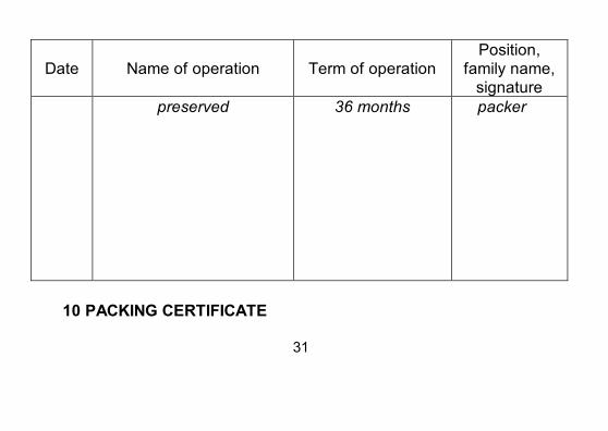
9 PRESERVATION
31
Date
Name of operation
Term of operation
Position, family name,
signature
preserved 36 months packer
10 PACKING CERTIFICATE

32
Autoloading hunting rifle version “VEPR-308 SUPER”, cal..308 Win, conventional name СОК-95М, factory No. ___________________ is packed at the “Molot-Oruzhie Ltd” in full compliance with the approved technical documentation. ____packer_____ ________________ ________________________ position signature year, month, date 11 ACCEPTANCE CERTIFICATE

33
Autoloading hunting rifle version “VEPR-308 SUPER”, cal..308 Win,
conventional name СОК-95М, factory No. ___________________ is manufactured and accepted in full compliance with the approved technical documentation and found fit for service, tested on safety and in conformity with safety requirements.
Manufacture date _______________________
Signature of person in charge of acceptance __________________
CONTENTS

34
1 General Indications 3 2 Purpose 5 3 Technical Data 6 4 Standard Equipment 7 5 Design and Principle of Operation of rifle 8 6 Safety Precautions 10 7 Preparation and Operation Order 12 8 Maintenance 16 9 Preservation 29 10
Packing Certificate 30
11
Acceptance Certificate 31

35