Embed Size (px)
Citation preview

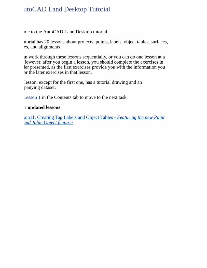
WelcometotheAutoCADLandDesktoptutorial.
Thistutorialhas20lessonsaboutprojects,points,labels,objecttables,surfaces,volumes,andalignments.
Youcanworkthroughtheselessonssequentially,oryoucandoonelessonatatime.However,afteryoubeginalesson,youshouldcompletetheexercisesintheorderpresented,asthefirstexercisesprovideyouwiththeinformationyouneedforthelaterexercisesinthatlesson.
Everylesson,exceptforthefirstone,hasatutorialdrawingandanaccompanyingdataset.
ClickLesson1intheContentstabtomovetothenexttask.
Neworupdatedlessons:
Lesson11:CreatingTagLabelsandObjectTables-FeaturingthenewPointTableandTableObjectfeatures
AutoCADLandDesktopTutorial
WelcometotheAutoCADLandDesktoptutorial.
Thistutorialhas20lessonsaboutprojects,points,labels,objecttables,surfaces,volumes,andalignments.
Youcanworkthroughtheselessonssequentially,oryoucandoonelessonatatime.However,afteryoubeginalesson,youshouldcompletetheexercisesintheorderpresented,asthefirstexercisesprovideyouwiththeinformationyouneedforthelaterexercisesinthatlesson.
Everylesson,exceptforthefirstone,hasatutorialdrawingandanaccompanyingdataset.
Lesson1intheContentstabtomovetothenexttask.
Neworupdatedlessons:
Lesson11:CreatingTagLabelsandObjectTables-FeaturingthenewPointTableandTableObjectfeatures
AutoCADLandDesktopTutorial
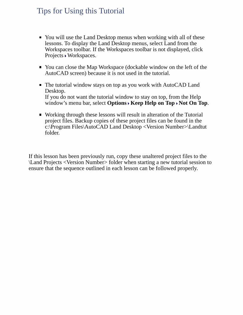
YouwillusetheLandDesktopmenuswhenworkingwithalloftheselessons.TodisplaytheLandDesktopmenus,selectLandfromtheWorkspacestoolbar.IftheWorkspacestoolbarisnotdisplayed,clickProjects Workspaces.
YoucanclosetheMapWorkspace(dockablewindowontheleftoftheAutoCADscreen)becauseitisnotusedinthetutorial.
ThetutorialwindowstaysontopasyouworkwithAutoCADLandDesktop.Ifyoudonotwantthetutorialwindowtostayontop,fromtheHelpwindow’smenubar,selectOptions KeepHelponTop NotOnTop.
WorkingthroughtheselessonswillresultinalterationoftheTutorialprojectfiles.Backupcopiesoftheseprojectfilescanbefoundinthec:\ProgramFiles\AutoCADLandDesktop<VersionNumber>\Landtutfolder.
Ifthislessonhasbeenpreviouslyrun,copytheseunalteredprojectfilestothe\LandProjects<VersionNumber>folderwhenstartinganewtutorialsessiontoensurethatthesequenceoutlinedineachlessoncanbefollowedproperly.
TipsforUsingthisTutorial

OneofthefirstrequirementsofworkingwithAutoCADLandDesktopisthatyourdraftinganddesigningenvironment(yourdrawingfile)mustbelinkedtoaproject.Aprojectissimplyastorageareaforadrawing'sassociateddata,whichcanincludepoints,surfaces,alignments,pipes,parcels,andsurveyobservations.
Projectdataisnotstoredinthedrawing,butinseparatefoldersonyoursystem.
Toworkthroughthislessonfollowthesesteps
1. StartAutoCADLandDesktopifyouhavenotalreadydoneso.
2. OntheProjectsmenu,clickWorkspacestodisplaytheWorkspacestoolbar.Inthelist,selectLandDesktoptodisplaytheLandDesktopmenus.
Workingthroughtheselessonswillresultinalterationoftheprojectfiles.Backupcopiesoftheseprojectfilescanbefoundinthec:\ProgramFiles\AutoCADLandDesktop<VersionNumber>\Landtutfolder.
Ifthislessonhasbeenpreviouslyrun,copytheseunalteredprojectfilestothe\LandProjects<VersionNumber>folderwhenstartinganewtutorialsessiontoensurethatthesequenceoutlinedineachlessoncanbefollowedproperly.
LESSON1:WorkingwithProjects
Inthisexercise,youwillstartanewdrawingandcreateanewprojecttostoreassociateddata.
1. OntheFilemenu,clickNewtodisplaytheNewDrawing:ProjectBaseddialogbox.
2. EnterLesson_1fortheName.
3. IntheProjectandDrawingLocationsection,verifythatProjectPathlistdisplays\LandProjects<VersionNumber>\,andthenclickCreateProjecttodisplaytheProjectDetailsdialogbox.
4. IntheInitialSettingsforNewDrawingssection,fromthePrototypelist,selectDefault(Meters).
5. IntheProjectInformationsection,enterProject_1fortheName.
6. EnterProjectforExploringLandDesktopStartupfortheDescriptionandTrainingfortheKeywords.
7. IntheDrawingPathforthisProjectsection,verifythatProject"DWG"Folderisselected.
8. ClickOKtoreturntotheNewDrawing:ProjectBaseddialogbox.
9. IntheSelectDrawingTemplatesection,clickBrowseandbrowsetotheTemplatefolderunderthelocationoftheLandDesktop<VersionNumber>installation(bydefaultc:\ProgramFiles\AutoCADLandDesktop<VersionNumber>\Template),andfromtheTemplatelist,selectaec_m.dwt.
10. IntheProjectandDrawingLocationsection,verifythattheProjectNamelistdisplaysProject_1andtheDrawingPathlistdisplays\LandProjects<VersionNumber>\Project_1\dwg\.
11. ClickOKtocreatethenewdrawingandproject.
CreatingaNewDrawingandProject
Inthisexercise,youwillspecifytheparametersforthenewdrawing.
1. AstheLoadSettingsdialogboxisdisplayed,verifythatthePathisC:\DocumentsandSettings\AllUsers\ApplicationData\Autodesk\AutoCADLandDesktop<VersionNumber>\<ReleaseNumber>\Data\setup\.
2. IntheLoadaDrawingSetupProfilesection,fromtheProfileNamelist,selectm500.set(Metric,1:500),andthenclickViewtodisplaytheViewDrawingSetupProfiledialogbox.
Thecoordinatezone,textstyle,anddrawingborderlistedneedtobechangedforthisdrawing,sointhefollowingstepsyouwillmaketheappropriateeditstothedrawingsetup.
3. ClickOKtoreturntotheLoadSettingsdialogbox,andthenclickLoadtoloadthem500setupprofile.
4. ClickNexttodisplaytheUnitsdialogboxandverifytheunitssettings.
5. ClickNexttodisplaytheScaledialogboxandverifythescalesettings.
Thehorizontaldrawingscaleaffectsblockinsertionandthesizeoftextthatisautomaticallycreated.Theverticaldrawingscalecontrolsonlythedefaultverticalexaggerationofprofilesandcrosssectionscreatedbythecivilengineeringtools.
6. ClickNexttodisplaytheZonedialogbox.
7. FromtheCategorieslist,selectUTM,NAD83Datum,andthenfromtheAvailableCoordinateSystemslistselectUTMwithNAD83Datum,Zone11,Meter;CentralMeridian117dW.
8. ClickNexttodisplaytheOrientationdialogboxandverifytheorientationsettings.
9. ClickNexttodisplaytheTextStyledialogbox,fromtheStyleSetNamelist,selectmleroy.stp,andthenclickLoadtoloadthemleroytextstyle.
10. FromtheSelectCurrentStylelist,selectL100.
11. ClickNexttodisplaytheBorderdialogbox.
SettingUptheNewDrawing
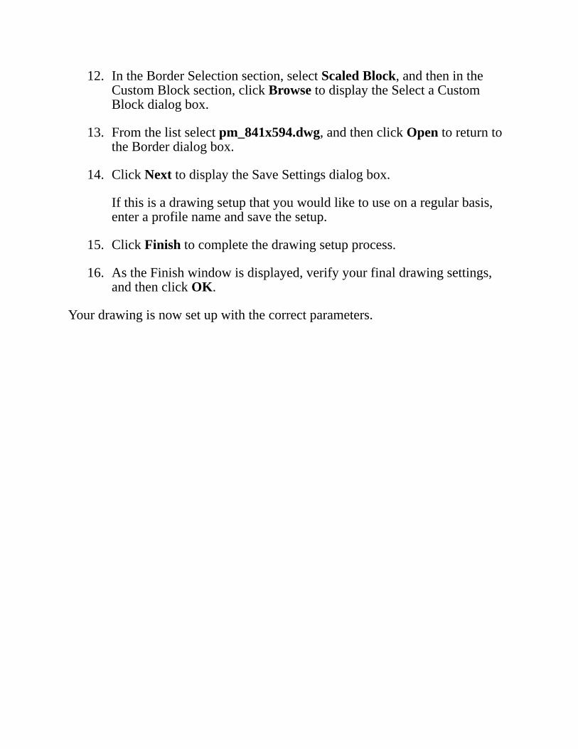
12. IntheBorderSelectionsection,selectScaledBlock,andthenintheCustomBlocksection,clickBrowsetodisplaytheSelectaCustomBlockdialogbox.
13. Fromthelistselectpm_841x594.dwg,andthenclickOpentoreturntotheBorderdialogbox.
14. ClickNexttodisplaytheSaveSettingsdialogbox.
Ifthisisadrawingsetupthatyouwouldliketouseonaregularbasis,enteraprofilenameandsavethesetup.
15. ClickFinishtocompletethedrawingsetupprocess.
16. AstheFinishwindowisdisplayed,verifyyourfinaldrawingsettings,andthenclickOK.
Yourdrawingisnowsetupwiththecorrectparameters.
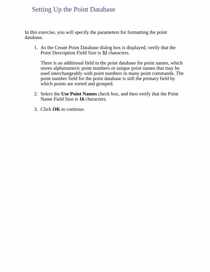
Inthisexercise,youwillspecifytheparametersforformattingthepointdatabase.
1. AstheCreatePointDatabasedialogboxisdisplayed,verifythatthePointDescriptionFieldSizeis32characters.
Thereisanadditionalfieldinthepointdatabaseforpointnames,whichstoresalphanumericpointnumbersoruniquepointnamesthatmaybeusedinterchangeablywithpointnumbersinmanypointcommands.Thepointnumberfieldforthepointdatabaseisstilltheprimaryfieldbywhichpointsaresortedandgrouped.
2. SelecttheUsePointNamescheckbox,andthenverifythatthePointNameFieldSizeis16characters.
3. ClickOKtocontinue.
SettingUpthePointDatabase
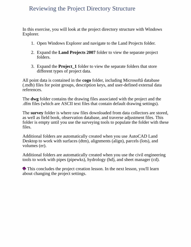
Inthisexercise,youwilllookattheprojectdirectorystructurewithWindowsExplorer.
1. OpenWindowsExplorerandnavigatetotheLandProjectsfolder.
2. ExpandtheLandProjects2007foldertoviewtheseparateprojectfolders.
3. ExpandtheProject_1foldertoviewtheseparatefoldersthatstoredifferenttypesofprojectdata.
Allpointdataiscontainedinthecogofolder,includingMicrosoftâdatabase(.mdb)filesforpointgroups,descriptionkeys,anduser-definedexternaldatareferences.
Thedwgfoldercontainsthedrawingfilesassociatedwiththeprojectandthe.dfmfiles(whichareASCIItextfilesthatcontaindefaultdrawingsettings).
Thesurveyfolderiswhererawfilesdownloadedfromdatacollectorsarestored,aswellasfieldbook,observationdatabase,andtraverseadjustmentfiles.Thisfolderisemptyuntilyouusethesurveyingtoolstopopulatethefolderwiththesefiles.
AdditionalfoldersareautomaticallycreatedwhenyouuseAutoCADLandDesktoptoworkwithsurfaces(dtm),alignments(align),parcels(lots),andvolumes(er).
Additionalfoldersareautomaticallycreatedwhenyouusethecivilengineeringtoolstoworkwithpipes(pipewks),hydrology(hd),andsheetmanager(cd).
Thisconcludestheprojectcreationlesson.Inthenextlesson,you'lllearnaboutchangingtheprojectsettings.
ReviewingtheProjectDirectoryStructure
Inthisexercise,youwilllookattheprojectdirectorystructurewithWindowsExplorer.
1. OpenWindowsExplorerandnavigatetotheLandProjectsfolder.
2. ExpandtheLandProjects2007foldertoviewtheseparateprojectfolders.
3. ExpandtheProject_1foldertoviewtheseparatefoldersthatstoredifferenttypesofprojectdata.
Allpointdataiscontainedinthecogofolder,includingMicrosoftâdatabase(.mdb)filesforpointgroups,descriptionkeys,anduser-definedexternaldatareferences.
dwgfoldercontainsthedrawingfilesassociatedwiththeprojectandthe.dfmfiles(whichareASCIItextfilesthatcontaindefaultdrawingsettings).
surveyfolderiswhererawfilesdownloadedfromdatacollectorsarestored,aswellasfieldbook,observationdatabase,andtraverseadjustmentfiles.Thisfolderisemptyuntilyouusethesurveyingtoolstopopulatethefolderwiththese
AdditionalfoldersareautomaticallycreatedwhenyouuseAutoCADLandDesktoptoworkwithsurfaces(dtm),alignments(align),parcels(lots),andvolumes(er).
Additionalfoldersareautomaticallycreatedwhenyouusethecivilengineeringtoolstoworkwithpipes(pipewks),hydrology(hd),andsheetmanager(cd).
Thisconcludestheprojectcreationlesson.Inthenextlesson,you'lllearnaboutchangingtheprojectsettings.
ReviewingtheProjectDirectoryStructure
Copyprojectstouseprojectdatawithotherdrawings.Changedrawingsettingstospecifynewannotation,objectcreation,andcalculationdefaults.
Toworkthroughthislessonfollowthesesteps
1. StartAutoCADLandDesktopifyouhavenotalreadydoneso.
2. OntheProjectsmenu,clickWorkspacestodisplaytheWorkspacestoolbar.Inthelist,selectLandDesktoptodisplaytheLandDesktopmenus.
Thedefaultlocationfolderforprojectfilesisc:\LandProjects<VersionNumber>.Ifyouoptedtoinstallthesefilesinanotherlocationinstead,specifytheappropriateprojectpath.
Workingthroughtheselessonswillresultinalterationoftheprojectfiles.Backupcopiesoftheseprojectfilescanbefoundinthec:\ProgramFiles\AutoCADLandDesktop<VersionNumber>\Landtutfolder.
Ifthislessonhasbeenpreviouslyrun,copytheseunalteredprojectfilestothe\LandProjects<VersionNumber>folderwhenstartinganewtutorialsessiontoensurethatthesequenceoutlinedineachlessoncanbefollowedproperly.
LESSON2:ChangingProjectSettings

AportionoftheLesson-2tutorialdrawingmustbeworkedonasaseparateproject.Sincesomeoftheimportantdataisnotstoredinthedrawingbutisstoredintheprojectfiles,acopyoftheprojectisrequired.
Youcannotcopyanactive,currentproject.Tocopyaproject,startanewsessionofAutoCADLandDesktopand,beforestartinganameddrawingorassociatingitwithaproject,opentheProjectManagementdialogboxandusetheCopyoption.
1. FromtheProjectsmenu,clickProjectManagertodisplaytheProjectManagementdialogbox.
2. IntheProjectsection,fromtheNamelist,selectTutorial1,andthenclickCopytodisplaytheCopydialogbox.
3. IntheCopyProjectTosection,enterTutorialCfortheName.
4. EnterBuildingsite-NorthwestcornerfortheDescription,andthenclickOK.
Thecopiedprojecthasthesamedirectorystructureastheoriginalproject,withthesamefilespopulatingeachfolder.
5. AsanAutoCADmessagedialogboxisdisplayed,clickYestochangetheprojectassociationandtoreturntotheProjectManagementdialogbox.
6. ClickClosetoclosetheProjectManagementdialogbox.
UsethefollowingstepstoopentheLesson-2tutorialdrawing.
7. OntheFilemenu,clickOpentodisplaytheOpenDrawing:ProjectBaseddialogbox.
8. FromtheProjectNamelist,selectTutorialC,fromtheSelectProjectDrawingList,selectLesson-2.dwg,andthenclickOK.
CopyingaProjectandRe-associatingtheCurrentDrawing
Inthisexercise,youwillchangethehorizontaldrawingscaleandseehowtextheightisaffected.Atthecurrenthorizontalscaleof1:500,the2MMtextstyleis1drawingunithigh.Theplotscalefora1:500scaledrawingis2withplottingunitsinmillimeters.Thisresultsin2MMtextstylebeingplottedwitha2mmheight.
1. OnthecommandlineenterSTtodisplaytheTextStyledialogbox.
2. FromtheStyleNamelist,select2MM,intheFontsection,enter1fortheHeight,clickApply,andthenclickClosetocontinue.
Usethefollowingstepstochangethehorizontaldrawingscaleto1:1000.
3. OntheProjectsmenu,clickDrawingSetuptodisplaytheDrawingSetupdialogbox.
4. ClicktheScaletab,intheDrawingScalesection,fromtheHorizontallist,select1:1000,andthenclickOK.
5. Onthecommandline,enterSTtodisplaytheTextStyledialogbox.
6. Verifythattheheightofthe2MMtextstyleis2,andthenclickCanceltocontinue.
Theplotscalefora1:1000scaledrawingis1withplottingunitsinmillimeters.Again,thisresultsin2MMtextstylebeingplottedwitha2mmheight.TheappropriatescalingoftextstylesoccurswithalltextstylesthatyouusewhenworkingwithAutoCADLandDesktop.
Usethefollowingstepstochangetheprecisionofelevationvaluesto1.
7. OntheProjectsmenu,clickDrawingSetuptodisplaytheDrawingSetupdialogbox.
8. ClicktheUnitstab.IntheDisplayPrecisionsection,fromtheElevationlist,select1,andthenintheSamplessectionverifythechangetothesampleelevationvalue.
Thischangeaffectsallfutureelevationvaluesinthisdrawing,includingpointmarkerelevationtext.
ChangingDrawingSetupParameters
Usethefollowingstepstochangethedrawingbasepointandnorthrotationangle.
9. ClicktheOrientationtab.IntheBasePointsection,clickPick,andthenuseaNodeOsnaptoselectpointnumber10fortheBasepoint.
10. AstheDrawingSetupdialogboxisdisplayedagain,intheNorthingandEastingsection,enter5000fortheNorthingand5000fortheEasting.
11. IntheNorthRotationsection,enter13.2450fortheAngle,andthenclickOK.
InAutoCADLandDesktop,northrotationanglesarerepresentedindegrees,minutes,andseconds.Thevalue,13.2450,represents13degrees,24minutes,and50seconds,notadecimaldegreevalue.
12. AsanAutoCADmessagedialogboxisdisplayed,clickOKtocontinue.
Usethefollowingstepstoinsertanortharrowtoshowthenorthrotation.
13. OntheUtilitiesmenu,clickSymbolManagertodisplaytheSymbolManagerdialogbox.
14. VerifythatCOGOSymbolsisdisplayedintheSymbolSetlist.FromthePalettelistselectDetails,selectNorthArrow,andthenclickOK.
15. Specifyaninsertionpointforthenortharrow,thepressENTERtoacceptthedefault,Magnetic,forthedescription.
Clickheretoseeanillustrationofthenortharrow.
Inthisexercise,youwilleditsettingsforthecurrentdrawing,andthensavethemtoaprototypesothesesettingscanbereused.
1. OntheProjectsmenu,clickEditDrawingSettingstodisplaytheEditSettingsdialogbox.
2. VerifythattheProgramlistdisplaysAutoCADLandDesktop.
3. FromtheSettingslist,selectGeodeticLabels,andthenclickEditSettingstodisplaytheGeodeticAnnotationSettingsdialogbox.
4. IntheLineAnnotationsection,intheAzcolumn,cleartheGridandGroundcheckboxes.
5. IntheSuffixcolumn,entermfortheGrid,Ground,andGeodeticsuffixes.
6. IntheDistanceUnitcolumn,selectMETERSfromtheGrid,Ground,andGeodeticlists.
7. ClickOKtoreturntotheEditSettingsdialogbox.
Thesesettingsonlyapplytothecurrentdrawing.Savethesesettingstoaprototypesothatfutureprojectscanusethesesettings.
8. IntheSelectedItemsection,clickSavetoPrototypetodisplaytheSelectPrototypedialogbox.
9. FromtheSelectPrototypelist,selectDEFAULT(METERS),clickOKtoreturntotheEditSettingsdialogbox,andthenclickClose.
Younowhaveaprototypedrawingsetupthatyoucanuseforsubsequentprojects.
Thisconcludestheprojectsettingslesson.Inthenextlesson,you'lllearnaboutpointobjects.
EditingDrawingSettings
PointsobjectsrepresentexistingorproposedpointsinLandDesktop.TheirappearanceinthedrawingandtheirinteractionwithAutoCADcommandscanbecontrolledbypointsettings.
Pointobjectshavethefollowingcharacteristics:
Pointscanappearattheiractualelevationoratafixedelevation.
Pointsaresavedtoanexternaldatabase.
Pointshavemarkersandtext;bothhavestylesthatcanbemodified.Pointscanalsobelabeledusingalabelstyle.
Markersandtextcanhaveeitherrelativeorabsolutesizescontrollingtheirappearanceinthedrawing.
Pointtextcanbeseparatedfromitsassociatedpointmarkerbygripediting,withaleaderautomaticallygeneratedtographicallylinkthemarkerandtext.
Pointdescriptionscanbeeitherraw(pointdatabase)orfull(asspecifiedbythedescriptionkey).
Pointtextappearsonthesamelayerasthepointmarker,butthevisibilityofthetextiscontrolledbyindividualsettings.
PointcoordinatedisplayindialogboxescanbespecifiedasNorthing/Easting,Easting/Northing,x,y,ory,x.
TheAutoCADUNDOcommandworkswithpointobjects.
PointobjectsalignwiththeWorldUCS.
Toworkthroughthislessonfollowthesesteps
1. StartAutoCADLandDesktopifyouhavenotalreadydoneso.
2. OntheFilemenu,clickOpentodisplaytheOpenDrawing:ProjectBaseddialogbox.
Thedefaultlocationfolderforprojectfilesisc:\LandProjects<VersionNumber>.Ifyouoptedtoinstallthesefilesinanotherlocationinstead,
LESSON3:WorkingwithPointObjects
specifytheappropriateprojectpath.
3. FromtheProjectNamelist,selectTUTORIAL2,fromtheSelectProjectDrawinglist,selectLesson-3.dwg,andthenclickOK.
4. OntheProjectsmenu,clickWorkspaces.Inthelist,selectLandDesktoptodisplaytheLandDesktopmenus.
Workingthroughtheselessonswillresultinalterationoftheprojectfiles.Backupcopiesoftheseprojectfilescanbefoundinthec:\ProgramFiles\AutoCADLandDesktop<VersionNumber>\Landtutfolder.
Ifthislessonhasbeenpreviouslyrun,copytheseunalteredprojectfilestothe\LandProjects<VersionNumber>folderwhenstartinganewtutorialsessiontoensurethatthesequenceoutlinedineachlessoncanbefollowedproperly.
Twopointsaredisplayedinthedrawing,247and758.UsetheAutoCADLISTcommandtolistinformationaboutthepointnumber247.
1. EnterLIST,andthenselectpointnumber247andpressENTER.
2. Closethetextwindow.
ThepointisanAECC_POINTobject.Thepointobjectappearsinthedrawingatitsactualelevation.Thepointcoordinates,description,pointnumber,andpointnamearestoredinthepointdatabase.
ListingPointObjects
Youcanerasepointsfromthedrawing,buttheystillexistinthepointsdatabase.Erasepointnumber247and758,andthenreinsertthem.
1. Onthecommandline,enterERASE,selectthetwopoints,andthenpressENTER.
2. OnthePointsmenu,clickPointUtilities ZoomtoExtents.
TheZoomtoExtentscommandzoomstotheextentsoftheminimumandmaximumcoordinatesofthepointsinthedatabase,nottheextentsofalloftheentitiesinthedrawing.
3. OnthePointsmenu,clickPointUtilities QuickView.
Xsappearatallpointlocations,includingtheerasedones.
Clickheretoseeanillustrationofthequickviewpointlocations.
Usethefollowingstepstolistallofthepointsinthedatabase.
4. OnthePointsmenu,clickListPointstodisplaytheListPointsdialogbox.
5. SelecttheListAllPointsoption.
6. Scrolldownthelisttoviewpoints247and758.
Pointnumber247islistedas247L,whichmeansitislocked.Lockedpointscannotbeediteduntiltheyareunlocked.
7. ClickOKtocontinue.
8. OntheViewmenu,clickNamedViewstodisplaytheViewdialogbox.UnderName,select1,clickSetCurrent,andthenclickOK.
Usethefollowingsteptoretrievethetwoerasedpointsfromthepointsdatabaseandreinserttheminthedrawing.
9. OnthePointsmenu,clickInsertPointstoDrawing,enterWfortheWindowoption,andthenwindowintheareaofthetwomissingpoints.(Thetwopointsarelocatedintherighthalfofthescreeninthecurrentview.)
InsertingPointsfromthePointDatabase

Thetwopointsnowreappearinthedrawing.
Clickheretoseeanillustrationofthereinsertedpoints.
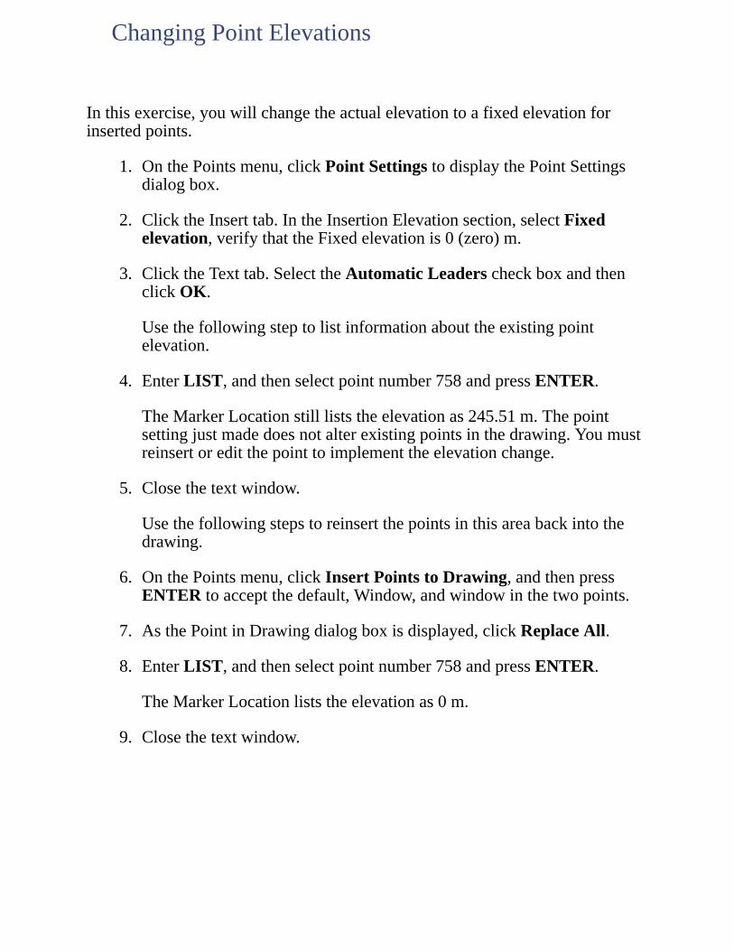
Inthisexercise,youwillchangetheactualelevationtoafixedelevationforinsertedpoints.
1. OnthePointsmenu,clickPointSettingstodisplaythePointSettingsdialogbox.
2. ClicktheInserttab.IntheInsertionElevationsection,selectFixedelevation,verifythattheFixedelevationis0(zero)m.
3. ClicktheTexttab.SelecttheAutomaticLeaderscheckboxandthenclickOK.
Usethefollowingsteptolistinformationabouttheexistingpointelevation.
4. EnterLIST,andthenselectpointnumber758andpressENTER.
TheMarkerLocationstillliststheelevationas245.51m.Thepointsettingjustmadedoesnotalterexistingpointsinthedrawing.Youmustreinsertoreditthepointtoimplementtheelevationchange.
5. Closethetextwindow.
Usethefollowingstepstoreinsertthepointsinthisareabackintothedrawing.
6. OnthePointsmenu,clickInsertPointstoDrawing,andthenpressENTERtoacceptthedefault,Window,andwindowinthetwopoints.
7. AsthePointinDrawingdialogboxisdisplayed,clickReplaceAll.
8. EnterLIST,andthenselectpointnumber758andpressENTER.
TheMarkerLocationliststheelevationas0m.
9. Closethetextwindow.
ChangingPointElevations
Inthisexercise,youwilllookatsomeofthepointdisplayproperties.
1. Selectpointnumber758,right-clickandclickDisplayPropertiestodisplaythePointDisplayPropertiesdialogbox.
2. ClicktheResettab.InthePointElevationsection,selecttheResetPointElevationinDrawingcheckbox,selectActualElevation,andthenclickOK.
3. EnterLIST,andthenselectbothpointsandpressENTER.
Forpointnumber758,observethattheMarkerLocationliststheelevationas245.51m.Forpointnumber247,theMarkerLocationliststheelevationas0m.ChangesmadeintheDisplayPropertiesdialogboxtakeimmediateeffect,withouthavingtoreinsertthepointsinthedrawing.
4. Closethetextwindow.
ChangingPointDisplayProperties
YoucanuseeithercustommarkersorAutoCADpointstodesignatepointnodes.IfyouchoosetouseAutoCADpointsasmarkers,themarkerstylecanbeadjustedwiththeDDPTYPEcommand.
Inthisexercise,youwillselectanewcustommarkerandsuperimposedsymbol,andthensizethemarkerinabsoluteunits.
1. OntheViewmenu,clickNamedViewstodisplaytheViewdialogbox.UnderName,select3,clickSetCurrent,andthenclickOK.
2. Selectpointnumber758,right-clickandclickDisplayPropertiestodisplaythePointDisplayPropertiesdialogbox.
3. OntheMarkertab,intheCustomMarkerSymbolsection,selectthefourthmarkersymbol,andthenintheSuperimposedsection,selectthecirclesymbol.
4. IntheCustomMarkerSizesection,selectSizeinAbsoluteUnits,andthenenter2fortheSize.
Youcanchangethevisibilityandcolorofnumber,elevation,anddescriptiontext.
Usethefollowingstepstoturnoffthevisibilityoftheelevationtext,changethecolorofthedescriptiontext,andsizethetextinabsoluteunits.
5. ClicktheTexttab,andthenintheColorandVisibilitysection,clearthe(Elevation)Visiblecheckbox.
6. ClicktheDescriptioncolorboxtodisplaytheSelectaColordialogbox.FromtheStandardColorspaletteselectcyan(lightblue),andthenclickOKtoreturntothePointDisplayPropertiesdialogbox.
7. IntheStyleandSizesection,selectAbsoluteUnits,enter2fortheTextSize,andthenclickOK.
Forpointnumber758,thepointmarkerandtextnowappearsmaller,andthenumberanddescriptiontextstringsarecenteredonthemarker.Theappearanceofpoint247remainsunchangedsinceitstextsizeisstillrelativetotheviewareaofthescreen.
ChangingPointMarkersandText
Clickheretoseeanillustrationofthenewpoint758displayparameters.
Asyouzoominandoutofthedrawing,pointswithmarkersandtextsizedrelativetotheviewareaofthescreenareresizedeachtimethatthepointsareregenerated.
8. OnthePointsmenu,clickPointSettingstodisplaythePointSettingsdialogbox.
9. ClickthePreferencestab.InthePointDisplaysection,cleartheAlwaysRegeneratePointDisplayAfterZoomcheckbox,andthenclickOK.
10. OntheViewmenu,clickNamedViewstodisplaytheViewdialogbox.UnderName,select1,clickSetCurrent,andthenclickOK.
11. OnthecommandlineenterREGENtoregeneratethedrawing.
Pointnumber247isresizedproportionally,whilepointnumber758maintainsitsabsolutesize.Ifallofthepointsinthedrawinghavetheirmarkersandtextsettoabsolutesize,itisrecommendedthatyouturnofftheAlwaysRegeneratePointDisplayAfterZoomcheckboxtoimprovedisplayperformance.
Usethefollowingstepstorepositionpointtextrelativetothepointmarker.
12. Selectpointnumber247todisplayitsgrips.
13. Selectthegripanddragdowntotheright,andthenclicktofixthepointtextinitsnewposition.
Aleaderisautomaticallydrawnbetweenthetextandmarker.
Clickheretoseeanillustrationofthepointleader.
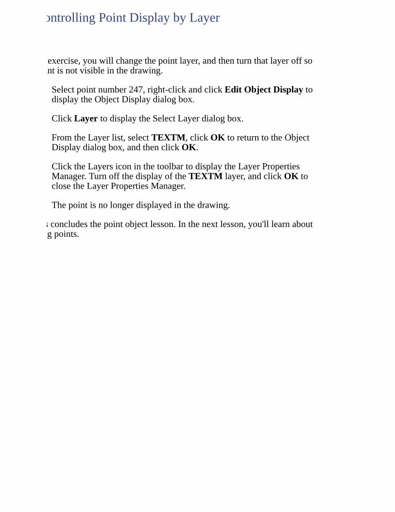
Inthisexercise,youwillchangethepointlayer,andthenturnthatlayeroffsothepointisnotvisibleinthedrawing.
1. Selectpointnumber247,right-clickandclickEditObjectDisplaytodisplaytheObjectDisplaydialogbox.
2. ClickLayertodisplaytheSelectLayerdialogbox.
3. FromtheLayerlist,selectTEXTM,clickOKtoreturntotheObjectDisplaydialogbox,andthenclickOK.
4. ClicktheLayersiconinthetoolbartodisplaytheLayerPropertiesManager.TurnoffthedisplayoftheTEXTMlayer,andclickOKtoclosetheLayerPropertiesManager.
Thepointisnolongerdisplayedinthedrawing.
Thisconcludesthepointobjectlesson.Inthenextlesson,you'lllearnaboutcreatingpoints.
ControllingPointDisplaybyLayer
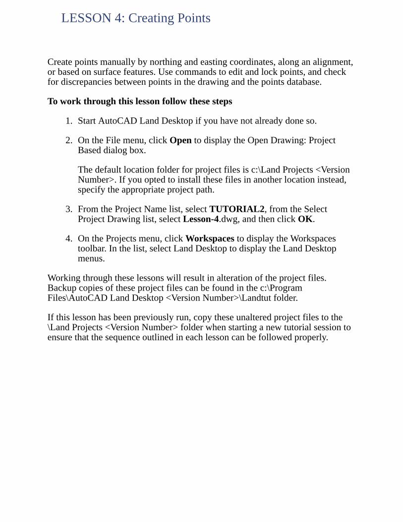
Createpointsmanuallybynorthingandeastingcoordinates,alonganalignment,orbasedonsurfacefeatures.Usecommandstoeditandlockpoints,andcheckfordiscrepanciesbetweenpointsinthedrawingandthepointsdatabase.
Toworkthroughthislessonfollowthesesteps
1. StartAutoCADLandDesktopifyouhavenotalreadydoneso.
2. OntheFilemenu,clickOpentodisplaytheOpenDrawing:ProjectBaseddialogbox.
Thedefaultlocationfolderforprojectfilesisc:\LandProjects<VersionNumber>.Ifyouoptedtoinstallthesefilesinanotherlocationinstead,specifytheappropriateprojectpath.
3. FromtheProjectNamelist,selectTUTORIAL2,fromtheSelectProjectDrawinglist,selectLesson-4.dwg,andthenclickOK.
4. OntheProjectsmenu,clickWorkspacestodisplaytheWorkspacestoolbar.Inthelist,selectLandDesktoptodisplaytheLandDesktopmenus.
Workingthroughtheselessonswillresultinalterationoftheprojectfiles.Backupcopiesoftheseprojectfilescanbefoundinthec:\ProgramFiles\AutoCADLandDesktop<VersionNumber>\Landtutfolder.
Ifthislessonhasbeenpreviouslyrun,copytheseunalteredprojectfilestothe\LandProjects<VersionNumber>folderwhenstartinganewtutorialsessiontoensurethatthesequenceoutlinedineachlessoncanbefollowedproperly.
LESSON4:CreatingPoints
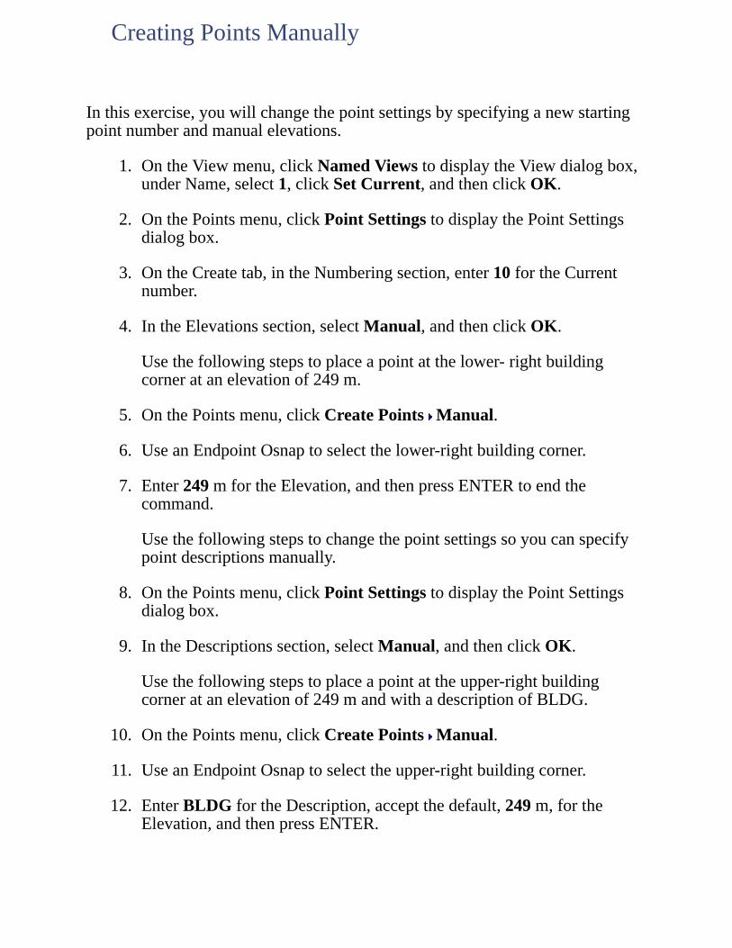
Inthisexercise,youwillchangethepointsettingsbyspecifyinganewstartingpointnumberandmanualelevations.
1. OntheViewmenu,clickNamedViewstodisplaytheViewdialogbox,underName,select1,clickSetCurrent,andthenclickOK.
2. OnthePointsmenu,clickPointSettingstodisplaythePointSettingsdialogbox.
3. OntheCreatetab,intheNumberingsection,enter10fortheCurrentnumber.
4. IntheElevationssection,selectManual,andthenclickOK.
Usethefollowingstepstoplaceapointatthelower-rightbuildingcorneratanelevationof249m.
5. OnthePointsmenu,clickCreatePoints Manual.
6. UseanEndpointOsnaptoselectthelower-rightbuildingcorner.
7. Enter249mfortheElevation,andthenpressENTERtoendthecommand.
Usethefollowingstepstochangethepointsettingssoyoucanspecifypointdescriptionsmanually.
8. OnthePointsmenu,clickPointSettingstodisplaythePointSettingsdialogbox.
9. IntheDescriptionssection,selectManual,andthenclickOK.
Usethefollowingstepstoplaceapointattheupper-rightbuildingcorneratanelevationof249mandwithadescriptionofBLDG.
10. OnthePointsmenu,clickCreatePoints Manual.
11. UseanEndpointOsnaptoselecttheupper-rightbuildingcorner.
12. EnterBLDGfortheDescription,acceptthedefault,249m,fortheElevation,andthenpressENTER.
CreatingPointsManually

Clickheretoseeanillustrationofthefirstandsecondpoints.
Inthisexercise,youwillcontinueplacingpointswithautomaticelevationsanddescriptions.
1. OnthePointsmenu,clickPointSettingstodisplaythePointSettingsdialogbox.
2. OntheCreatetab,intheElevationssection,selectAutomatic.
3. IntheDescriptionssection,selectAutomatic,andthenclickOK.
Usethefollowingstepstoplaceapointattheupper-leftbuildingcorneratanelevationof249mandwithadescriptionofBLDG.
4. OnthePointsmenu,clickCreatePoints Manual.
5. UseanEndpointOsnaptoselecttheupper-leftbuildingcorner,andthenpressENTER.
Thepointisplacedatanelevationof249mandwithadescriptionofBLDGautomatically.
Clickheretoseeanillustrationofthethirdpoint.
SpecifyingAutomaticElevationsandDescriptions
Inthisexercise,youwillchangethePointSettingssopointsarenolongerinsertedintothedrawing,andthencreateanotherpoint.
1. OnthePointsmenu,clickPointSettingstodisplaythePointSettingsdialogbox.
2. OntheCreatetab,intheNumberingsection,cleartheInserttoDrawingasCreatedcheckbox,andthenclickOK.
Usethefollowingstepstoplaceapointatthenextbuildingcorner.
3. OnthePointsmenu,clickCreatePoints Manual.
4. UseanEndpointOsnaptoselectthenextbuildingcorner,andthenpressENTER.
Thenewpointdoesnotappearinthedrawing.Usethefollowingstepstorestorethesettingsosubsequentpointsareinsertedintothedrawing,andinsertthepointyoujustcreatedintothedrawing.
5. OnthePointsmenu,clickPointSettingstodisplaythePointSettingsdialogbox.
6. OntheCreatetab,intheNumberingsection,selecttheInserttoDrawingasCreatedcheckbox,andthenclickOK.
7. OnthePointsmenu,clickInsertPointstoDrawing,enterNfortheNumbersoption,andthenenter13forthePointnumber.
Pointnumber13nowappearsinthedrawing.
Clickheretoseeanillustrationofthefourthpoint.
CreatingPointsinthePointsDatabase
Inthisexercise,youwillplacepointsattheremainingtwobuildingcorners.
1. OnthePointsmenu,clickCreatePoints Automatic.
2. Selecttheshortverticalbuildinglinesegmentonthebottomofthebuilding,andthenpressENTER.
Twopointsaresetattheendpointsoftheselectedlinesegment.
Clickheretoseeanillustrationofthefifthandsixthpoints.
PlacingPointsonanObject
Inthisexercise,youwillplacepointsalonganalignmentbetweenspecifiedstationsatanoffset.First,changetheviewandsetthecurrentalignment.
1. OntheViewmenu,clickNamedViewstodisplaytheViewdialogbox.UnderName,select2,clickSetCurrent,andthenclickOK.
2. OntheAlignmentsmenu,clickSetCurrentAlignment,andthenpressENTERtodisplaytheAlignmentLibrariandialogbox.
3. FromtheSelectionlist,selectP3_HWY69,andthenclickOK.
4. OnthePointsmenu,clickCreatePoints-Alignments MeasureAlignment.
5. Enter15500fortheBeginningstation,andthenenter16000fortheEndingstation.
6. Enter15mfortheOffset,enter50mfortheStationinterval,andthenenter25fortheCurrentpointnumber.
Elevenpointsaresetalongthealignment.
Clickheretoseeanillustrationofthepointssetalongthealignment.
PlacingPointsAlonganAlignment
Inthisexercise,youwillplacepointsontheexistinggroundsurfaceinagridpattern.
1. OntheViewmenu,clickNamedViewstodisplaytheViewdialogbox.UnderName,select3,clickSetCurrent,andthenclickOK.
UsethefollowingstepstosetEGasthecurrentsurface.
2. OntheTerrainmenu,clickSetCurrentSurfacetodisplaytheSelectSurfacedialogbox.
3. FromtheSelectsurfacetoopenlist,selectEG,andthenclickOK.
4. OnthePointsmenu,clickCreatePoints-Surface OnGrid.
5. PressENTERtoacceptthedefault,0(zero)degrees,fortheGridrotationangle.
6. UseanIntersectionOsnaptoselectthelower-leftcornerofthegridrectangle.
7. Enter50mfortheGridXSpacing,andthenpressENTERtoacceptthedefault,50m,fortheGridYspacing.
8. UseanIntersectionOsnaptoselecttheupper-rightcornerofthegridrectangle.
9. PressENTERtoacceptthedefault,No,toacceptthesizeorrotationofthegrid/gridsquares.
Pointsaresetatspecifiedgridnodeswithelevationsextractedfromthecurrentsurface.
Clickheretoseeanillustrationofthepointssetonthesurface.
Thisconcludesthepointcreationlesson.Inthenextlesson,you'lllearnabouteditingpoints.
PlacingPointsonaSurface
Usethepointeditingcommandstomodifyexistingpointnumbers,coordinates,anddescriptions.
Toworkthroughthislessonfollowthesesteps
1. StartAutoCADLandDesktopifyouhavenotalreadydoneso.
2. OntheFilemenu,clickOpentodisplaytheOpenDrawing:ProjectBaseddialogbox.
Thedefaultlocationfolderforprojectfilesisc:\LandProjects<VersionNumber>.Ifyouoptedtoinstallthesefilesinanotherlocationinstead,specifytheappropriateprojectpath.
3. FromtheProjectNamelist,selectTUTORIAL2,fromtheSelectProjectDrawinglist,selectLesson-5.dwg,andthenclickOK.
4. OntheProjectsmenu,clickWorkspacestodisplaytheWorkspacestoolbar.Inthelist,selectLandDesktoptodisplaytheLandDesktopmenus.
Workingthroughtheselessonswillresultinalterationoftheprojectfiles.Backupcopiesoftheseprojectfilescanbefoundinthec:\ProgramFiles\AutoCADLandDesktop<VersionNumber>\Landtutfolder.
Ifthislessonhasbeenpreviouslyrun,copytheseunalteredprojectfilestothe\LandProjects<VersionNumber>folderwhenstartinganewtutorialsessiontoensurethatthesequenceoutlinedineachlessoncanbefollowedproperly.
LESSON5:EditingPoints
Inthisexercise,youwillspecifypointstoeditbyselectingtheminthedrawing.
1. OntheViewmenu,clickNamedViewstodisplaytheViewdialogbox,underName,select1,clickSetCurrent,andthenclickOK.
2. OnthePointsmenu,clickEditPoints EditPointstodisplaytheEditPointsdialogbox.
3. SelecttheEnableFilteringoption.
4. ClicktheIncludetab.
5. SelecttheWithNumberMatchingcheckbox,andthenclicktheSelectionSetinDrawingbutton.
6. EnterWfortheWindowoptionandwindowinpoints247,248,and758,andthenpressENTER.
7. AstheEditPointsdialogboxisdisplayedagain,verifythatthethreepointsnowappearintheWithNumberMatchingbox.
8. ClicktheBuildListbuttontobuildthelistofpointstoedit.
9. ClicktheEdittab.
Pointnumber247islockedandcannotbeedited,buttheothertwopointsareunlockedandcanbeedited.Beforeyoueditthepoints,you'llexittheEditPointsdialogboxandunlockpoint247.
10. ClickOKtocontinue.
SelectingPointstoEdit
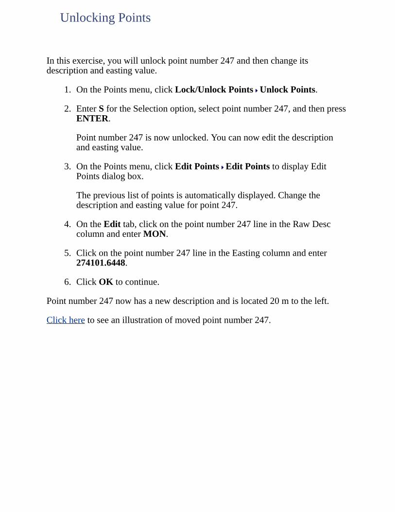
Inthisexercise,youwillunlockpointnumber247andthenchangeitsdescriptionandeastingvalue.
1. OnthePointsmenu,clickLock/UnlockPoints UnlockPoints.
2. EnterSfortheSelectionoption,selectpointnumber247,andthenpressENTER.
Pointnumber247isnowunlocked.Youcannoweditthedescriptionandeastingvalue.
3. OnthePointsmenu,clickEditPoints EditPointstodisplayEditPointsdialogbox.
Thepreviouslistofpointsisautomaticallydisplayed.Changethedescriptionandeastingvalueforpoint247.
4. OntheEdittab,clickonthepointnumber247lineintheRawDesccolumnandenterMON.
5. Clickonthepointnumber247lineintheEastingcolumnandenter274101.6448.
6. ClickOKtocontinue.
Pointnumber247nowhasanewdescriptionandislocated20mtotheleft.
Clickheretoseeanillustrationofmovedpointnumber247.
UnlockingPoints
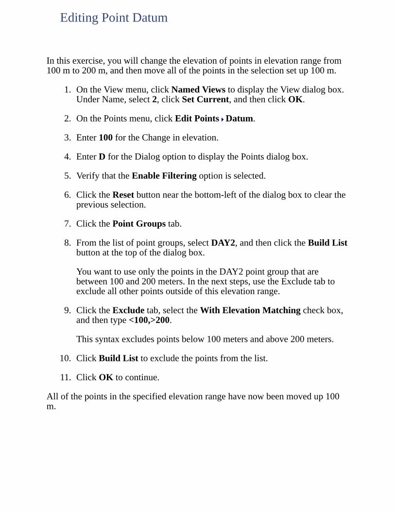
Inthisexercise,youwillchangetheelevationofpointsinelevationrangefrom100mto200m,andthenmoveallofthepointsintheselectionsetup100m.
1. OntheViewmenu,clickNamedViewstodisplaytheViewdialogbox.UnderName,select2,clickSetCurrent,andthenclickOK.
2. OnthePointsmenu,clickEditPoints Datum.
3. Enter100fortheChangeinelevation.
4. EnterDfortheDialogoptiontodisplaythePointsdialogbox.
5. VerifythattheEnableFilteringoptionisselected.
6. ClicktheResetbuttonnearthebottom-leftofthedialogboxtoclearthepreviousselection.
7. ClickthePointGroupstab.
8. Fromthelistofpointgroups,selectDAY2,andthenclicktheBuildListbuttonatthetopofthedialogbox.
YouwanttouseonlythepointsintheDAY2pointgroupthatarebetween100and200meters.Inthenextsteps,usetheExcludetabtoexcludeallotherpointsoutsideofthiselevationrange.
9. ClicktheExcludetab,selecttheWithElevationMatchingcheckbox,andthentype<100,>200.
Thissyntaxexcludespointsbelow100metersandabove200meters.
10. ClickBuildListtoexcludethepointsfromthelist.
11. ClickOKtocontinue.
Allofthepointsinthespecifiedelevationrangehavenowbeenmovedup100m.
EditingPointDatum
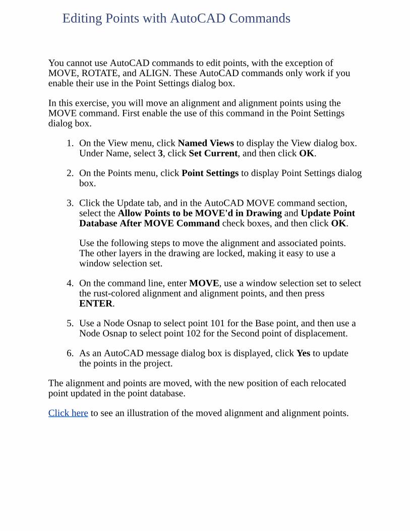
YoucannotuseAutoCADcommandstoeditpoints,withtheexceptionofMOVE,ROTATE,andALIGN.TheseAutoCADcommandsonlyworkifyouenabletheiruseinthePointSettingsdialogbox.
Inthisexercise,youwillmoveanalignmentandalignmentpointsusingtheMOVEcommand.FirstenabletheuseofthiscommandinthePointSettingsdialogbox.
1. OntheViewmenu,clickNamedViewstodisplaytheViewdialogbox.UnderName,select3,clickSetCurrent,andthenclickOK.
2. OnthePointsmenu,clickPointSettingstodisplayPointSettingsdialogbox.
3. ClicktheUpdatetab,andintheAutoCADMOVEcommandsection,selecttheAllowPointstobeMOVE'dinDrawingandUpdatePointDatabaseAfterMOVECommandcheckboxes,andthenclickOK.
Usethefollowingstepstomovethealignmentandassociatedpoints.Theotherlayersinthedrawingarelocked,makingiteasytouseawindowselectionset.
4. Onthecommandline,enterMOVE,useawindowselectionsettoselecttherust-coloredalignmentandalignmentpoints,andthenpressENTER.
5. UseaNodeOsnaptoselectpoint101fortheBasepoint,andthenuseaNodeOsnaptoselectpoint102fortheSecondpointofdisplacement.
6. AsanAutoCADmessagedialogboxisdisplayed,clickYestoupdatethepointsintheproject.
Thealignmentandpointsaremoved,withthenewpositionofeachrelocatedpointupdatedinthepointdatabase.
Clickheretoseeanillustrationofthemovedalignmentandalignmentpoints.
EditingPointswithAutoCADCommands
Inthisexercise,youwillusetheAutoCADUNDOcommandtomovethealignmentandpointsbacktotheiroriginalposition.However,thiswillnotupdatethepointdatabase,sousetheCheckPointscommandtoresolvethediscrepancybetweenthepositionofthepointsinthedrawingandthepointdatabase.
1. Onthecommandline,enterUNDO,pressENTER,andthenpressENTERagaintorestorethealignmentandpointstotheiroriginalposition.
2. OnthePointsmenu,clickCheckPoints ModifyProjecttodisplaytheModifyProjectDatabasePointsfromDrawingdialogbox.
3. IntheScanDrawingforsection,verifythatCOGOPointObjectsisselected.
4. IntheModifyProjectDatabasesection,verifythattheChangepointsinprojectdatabasecheckboxisselected,andthenclickOK.
Pointupdateinformationisdisplayedonthecommandline.
Thisconcludesthepointeditinglesson.Inthenextlesson,you'lllearnaboutpointgroups.
UsingCheckPoints
UsethePointGroupManagertocreatepointgroupsforuseinbuildingsurfacesorotherspecifictasks.
Toworkthroughthislessonfollowthesesteps
1. StartAutoCADLandDesktopifyouhavenotalreadydoneso.
2. OntheFilemenu,clickOpentodisplaytheOpenDrawing:ProjectBaseddialogbox.
Thedefaultlocationfolderforprojectfilesisc:\LandProjects<VersionNumber>.Ifyouoptedtoinstallthesefilesinanotherlocationinstead,specifytheappropriateprojectpath.
3. FromtheProjectNamelist,selectTUTORIAL2,fromtheSelectProjectDrawinglist,selectLesson-6.dwg,andthenclickOK.
4. OntheProjectsmenu,clickWorkspacestodisplaytheWorkspacestoolbar.Inthelist,selectLandDesktoptodisplaytheLandDesktopmenus.
Workingthroughtheselessonswillresultinalterationoftheprojectfiles.Backupcopiesoftheseprojectfilescanbefoundinthec:\ProgramFiles\AutoCADLandDesktop<VersionNumber>\Landtutfolder.
Ifthislessonhasbeenpreviouslyrun,copytheseunalteredprojectfilestothe\LandProjects<VersionNumber>folderwhenstartinganewtutorialsessiontoensurethatthesequenceoutlinedineachlessoncanbefollowedproperly.
LESSON6:WorkingwithPointGroups

Inthisexercise,youwillcreateagroupofpointstobeusedinbuildingasurfacethatincludespointsfromtheday-twosurvey,butexcludespointssuchasbenchmarksandtemporaryturningpoints.
1. OnthePointsmenu,clickPointManagement PointGroupManagertodisplaythePointGroupManagerdialogbox.
Someexistingpointgroupsaredisplayedintheleft-handpaneofthePointGroupManagerdialogbox.
Youwillnowcreateanewpointgroupbycopyinganexistingpointgroupandthenexcludingselectedpoints.
2. Right-clickthepointgroupnamedDAY2andselectCopyPointGrouptodisplaytheCreatePointGroupdialogbox.
3. EnterDAY2-DTMfortheGroupNameandthenclicktheExcludetab.
4. SelecttheWithRawDescMatchingcheckbox.
5. Enter92,93,94,95,96fortheDescription.
6. ClickApplytoexcludethespecifiedpointsfromthepointgroup.
ThePointListisupdatedtoreflecttheexcludedpoints.
7. ClickOKtoreturntothePointGroupManagerdialogbox.
ThenewpointgroupisdisplayedwiththeexistingpointgroupsandthepointlistinformationisdisplayedintherightpaneofthePointGroupManagerdialogbox.
CreatingaPointGroup

Inthisexercise,youwillcreateagroupofpointstobeusedinbuildingasurfacethatincludespointsfromtheday-twosurvey,butexcludespointssuchasbenchmarksandtemporaryturningpoints.
1. OnthePointsmenu,clickPointManagement PointGroupManagertodisplaythePointGroupManagerdialogbox.
Someexistingpointgroupsaredisplayedintheleft-handpaneofthePointGroupManagerdialogbox.
Youwillnowcreateanewpointgroupbycopyinganexistingpointgroupandthenexcludingselectedpoints.
2. Right-clickthepointgroupnamedDAY2andselectCopyPointGrouptodisplaytheCreatePointGroupdialogbox.
3. EnterDAY2-DTMfortheGroupNameandthenclicktheExcludetab.
4. SelecttheWithRawDescMatchingcheckbox.
5. Enter92,93,94,95,96fortheDescription.
6. ClickApplytoexcludethespecifiedpointsfromthepointgroup.
ThePointListisupdatedtoreflecttheexcludedpoints.
7. ClickOKtoreturntothePointGroupManagerdialogbox.
ThenewpointgroupisdisplayedwiththeexistingpointgroupsandthepointlistinformationisdisplayedintherightpaneofthePointGroupManagerdialog
CreatingaPointGroup

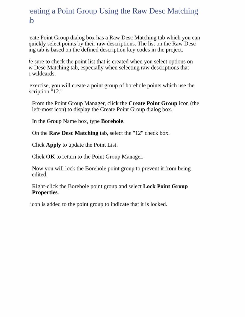
TheCreatePointGroupdialogboxhasaRawDescMatchingtabwhichyoucanusetoquicklyselectpointsbytheirrawdescriptions.ThelistontheRawDescMatchingtabisbasedonthedefineddescriptionkeycodesintheproject.
NoteBesuretocheckthepointlistthatiscreatedwhenyouselectoptionsontheRawDescMatchingtab,especiallywhenselectingrawdescriptionsthatcontainwildcards.
Inthisexercise,youwillcreateapointgroupofboreholepointswhichusetherawdescription"12."
1. FromthePointGroupManager,clicktheCreatePointGroupicon(theleft-mosticon)todisplaytheCreatePointGroupdialogbox.
2. IntheGroupNamebox,typeBorehole.
3. OntheRawDescMatchingtab,selectthe"12"checkbox.
4. ClickApplytoupdatethePointList.
5. ClickOKtoreturntothePointGroupManager.
NowyouwilllocktheBoreholepointgrouptopreventitfrombeingedited.
6. Right-clicktheBoreholepointgroupandselectLockPointGroupProperties.
Alockiconisaddedtothepointgrouptoindicatethatitislocked.
CreatingaPointGroupUsingtheRawDescMatchingTab
TheCreatePointGroupdialogboxhasaRawDescMatchingtabwhichyoucanusetoquicklyselectpointsbytheirrawdescriptions.ThelistontheRawDescMatchingtabisbasedonthedefineddescriptionkeycodesintheproject.
BesuretocheckthepointlistthatiscreatedwhenyouselectoptionsontheRawDescMatchingtab,especiallywhenselectingrawdescriptionsthatcontainwildcards.
Inthisexercise,youwillcreateapointgroupofboreholepointswhichusetherawdescription"12."
1. FromthePointGroupManager,clicktheCreatePointGroupicon(theleft-mosticon)todisplaytheCreatePointGroupdialogbox.
2. IntheGroupNamebox,typeBorehole.
3. OntheRawDescMatchingtab,selectthe"12"checkbox.
4. ClickApplytoupdatethePointList.
5. ClickOKtoreturntothePointGroupManager.
NowyouwilllocktheBoreholepointgrouptopreventitfrombeingedited.
6. Right-clicktheBoreholepointgroupandselectLockPointGroupProperties.
Alockiconisaddedtothepointgrouptoindicatethatitislocked.
CreatingaPointGroupUsingtheRawDescMatchingTab
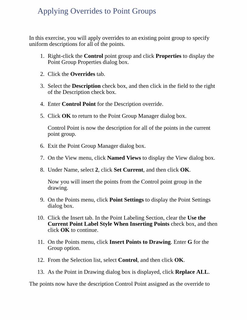
Inthisexercise,youwillapplyoverridestoanexistingpointgrouptospecifyuniformdescriptionsforallofthepoints.
1. Right-clicktheControlpointgroupandclickPropertiestodisplaythePointGroupPropertiesdialogbox.
2. ClicktheOverridestab.
3. SelecttheDescriptioncheckbox,andthenclickinthefieldtotherightoftheDescriptioncheckbox.
4. EnterControlPointfortheDescriptionoverride.
5. ClickOKtoreturntothePointGroupManagerdialogbox.
ControlPointisnowthedescriptionforallofthepointsinthecurrentpointgroup.
6. ExitthePointGroupManagerdialogbox.
7. OntheViewmenu,clickNamedViewstodisplaytheViewdialogbox.
8. UnderName,select2,clickSetCurrent,andthenclickOK.
NowyouwillinsertthepointsfromtheControlpointgroupinthedrawing.
9. OnthePointsmenu,clickPointSettingstodisplaythePointSettingsdialogbox.
10. ClicktheInserttab.InthePointLabelingSection,cleartheUsetheCurrentPointLabelStyleWhenInsertingPointscheckbox,andthenclickOKtocontinue.
11. OnthePointsmenu,clickInsertPointstoDrawing.EnterGfortheGroupoption.
12. FromtheSelectionlist,selectControl,andthenclickOK.
13. AsthePointinDrawingdialogboxisdisplayed,clickReplaceALL.
ThepointsnowhavethedescriptionControlPointassignedastheoverrideto
ApplyingOverridestoPointGroups

thepointgroup.
ClickheretoseeanillustrationofthepointswiththeControlPointoverride.
Pointsinsertedinthedrawingfromotherpointgroupswouldnotdisplaythisoverridedescription.

Inthisexercise,youwilldeleteapointthatisreferencedinseveralpointgroups.ThenyouwillusetheShowChangestoAllPointGroupsfeaturetocheckthepointgroupsforchangesandupdatethepointgroupstoremovethedeletedpoint.
1. OnthePointsmenu,clickPointSettings,thenclickthePreferencestab.
2. UnderPointGroupManager,verifythattheCheckStatusonStartupcheckboxisselected.
Thissettingdetectsandreportschangestopointgroupsiftheprojectpointdatabaseisaltered.
3. ClickOK.
4. OnthePointsmenu,clickEditPoints Erase.
5. TypeNtoselecttheNumbersoption.
6. Type1020andpressENTERtoerasepointnumber1020.
7. OnthePointsmenu,clickPointManagement PointGroupManager.
Noticethatthreeofthefourpointgroups,Borehole,Day2,andDay2-DTMarenowmarkedwithdifferenticonstoindicatethattheyareout-of-date.Inthiscase,thepointgroupsareconsideredtobeout-of-datebecausetheirpointlistsreferenceapointthatnolongerexistsintheproject.
8. ClicktheShowChangestoAllPointGroupsicon(thethirdiconfromtheleft).
ThePointGroupManagerchecksforchangestothepointgroupsandthendisplaystheChangedPointGroupsdialogbox.
TheAdd/Removecolumnindicateswhattypeofactionisrequiredinordertoupdatethepointgroup.Inthiscase,thecolumncontains"Remove"becausethepoint1020nolongerexistsintheprojectandshouldberemovedfromthepointgroups.
9. ClicktheUpdatePointGroup(s)icon.
UpdatingPointGroups
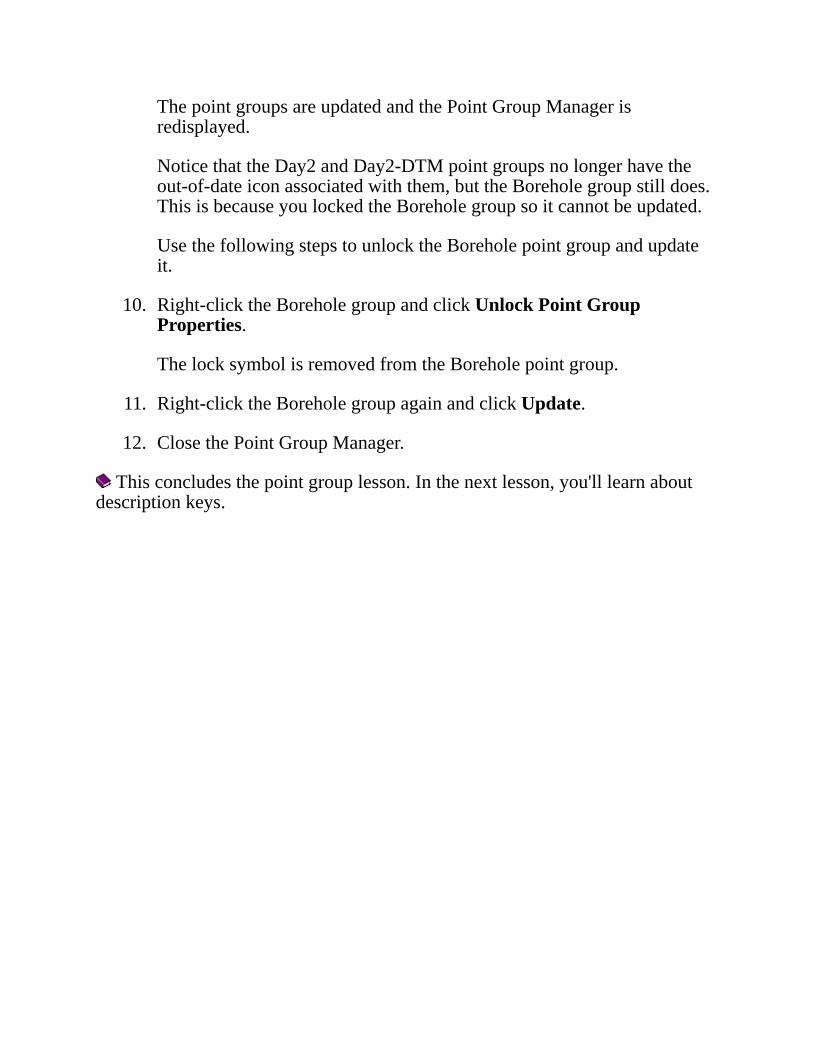
ThepointgroupsareupdatedandthePointGroupManagerisredisplayed.
NoticethattheDay2andDay2-DTMpointgroupsnolongerhavetheout-of-dateiconassociatedwiththem,buttheBoreholegroupstilldoes.ThisisbecauseyoulockedtheBoreholegroupsoitcannotbeupdated.
UsethefollowingstepstounlocktheBoreholepointgroupandupdateit.
10. Right-clicktheBoreholegroupandclickUnlockPointGroupProperties.
ThelocksymbolisremovedfromtheBoreholepointgroup.
11. Right-clicktheBoreholegroupagainandclickUpdate.
12. ClosethePointGroupManager.
Thisconcludesthepointgrouplesson.Inthenextlesson,you'lllearnaboutdescriptionkeys.
Usedescriptionkeystotranslaterawdescriptionsstoredinthepointdatabasetoafulldescription,toassociatesymbolswithpoints,andtocontrolpointandsymbollayers.
Toworkthroughthislessonfollowthesesteps
1. StartAutoCADLandDesktopifyouhavenotalreadydoneso.
2. OntheFilemenu,clickOpentodisplaytheOpenDrawing:ProjectBaseddialogbox.
Thedefaultlocationfolderforprojectfilesisc:\LandProjects<VersionNumber>.Ifyouoptedtoinstallthesefilesinanotherlocationinstead,specifytheappropriateprojectpath.
3. FromtheProjectNamelist,selectTUTORIAL2,fromtheSelectProjectDrawinglist,selectLesson-7.dwg,andthenclickOK.
4. OntheProjectsmenu,clickWorkspacestodisplaytheWorkspacestoolbar.Inthelist,selectLandDesktoptodisplaytheLandDesktopmenus.
Workingthroughtheselessonswillresultinalterationoftheprojectfiles.Backupcopiesoftheseprojectfilescanbefoundinthec:\ProgramFiles\AutoCADLandDesktop<VersionNumber>\Landtutfolder.
Ifthislessonhasbeenpreviouslyrun,copytheseunalteredprojectfilestothe\LandProjects<VersionNumber>folderwhenstartinganewtutorialsessiontoensurethatthesequenceoutlinedineachlessoncanbefollowedproperly.
LESSON7:OrganizingPointsbyDescriptions
Inthisexercise,youwillcreateadescriptionkeyfile.First,verifythesymbolpathforblockstobeinsertedwithpointsasspecifiedbydescriptionkeys.
1. OnthePointsmenu,clickPointSettingstodisplaythePointSettingsdialogbox.
2. ClicktheInserttab,intheSearchPathforSymbolBlockDrawingFilessection,clickBrowsetodisplaytheBrowseforFolderdialogbox.
3. FromtheSelectaPathlist,selectC:\DocumentsandSettings\AllUsers\ApplicationData\Autodesk\AutoCADLandDesktop<VersionNumber>\<ReleaseNumber>\Data\SymbolManager\Cogo_metric,andthenclickOKtoreturntothePointSettingsdialogbox.
4. InthePointLabelingsection,verifythattheUsetheCurrentPointLabelStyleWhenInsertingPointscheckboxisselected.
5. ClicktheDescriptionKeystab.IntheMatchingOptionssection,verifythattheMatchonDescriptionParameters($1,$2,etc.)checkboxisselected,andthenclickOK.
6. OnthePointsmenu,clickPointManagement DescriptionKeyManagertodisplaytheDescriptionKeyManagerdialogbox.
7. ClicktheCreateDescKeyFileicon(theleft-mosticon)todisplaytheCreateDescriptionKeyFiledialogbox.
8. EnterCREW-BfortheFilename,andthenclickOKtoreturntotheDescriptionKeyManagerdialogbox.
CreatingaDescriptionKeyFile
Inthisexercise,youwillcreatedescriptionkeysforobservationsofedgesofpavement,ironbars,andtreesforthenewdescriptionkeyfile.Notethatdescriptionkeyscodesarecase-sensitive;a"TREE"descriptionkeyisdifferentfroma"Tree"descriptionkey.
First,createanedgeofpavementdescriptionkey.
1. SelectCREW-B,andthenclicktheCreateDescKeyicon(thesecondiconfromtheleft)todisplaytheCreateDescriptionKeydialogbox.
2. EnterEPfortheDescKeyCode,andthenontheGeneraltab,enterEPfortheDescriptionFormatandPNT_EPforthePointLayer.
3. IntheSymbolInsertionsection,verifythattheSymbolBlockNamelistdisplays<none>,andthenclickOKtoreturntotheDescriptionKeyManagerdialogbox.
Usethefollowingstepstocreateanironbardescriptionkey.
4. ClicktheCreateDescKeyicontodisplaytheCreateDescriptionKeydialogbox.
5. EnterIBfortheDescKeyCode,andthenontheGeneraltab,enterIBfortheDescriptionFormatandPNT_IBforthePointLayer.
6. IntheSymbolInsertionsection,fromtheSymbolBlockNamelist,selectbound,andthenenterMONUMENTfortheSymbolLayer.
7. ClicktheScale/RotateSymboltab.IntheScaleSymbolBysection,verifythattheCurrentDrawingScale:1:1000checkboxisselected.
8. IntheApplyScaleTosection,verifythattheX-YDimensionscheckboxisselected,andthenclickOKtoreturntotheDescriptionKeyManagerdialogbox.
Usethefollowingstepstocreateatreedescriptionkeythathasadiameter-specificsymbol.
9. ClicktheCreateDescKeyicontodisplaytheCreateDescriptionKeydialogbox.
10. EnterTreefortheDescKeyCode,andthenontheGeneraltab,enter
CreatingDescriptionKeys
$2mm$1TreefortheDescriptionFormatandPNT_TREEforthePointLayer.
NoteThe$2mm$1TreeDescriptionFormatusesdescriptionparameters.Descriptionparametersmaintainbutreorderthedescriptiontextthatyouenter.Inlatersteps,you'llcreatesomepointsthatrepresenttrees.Byentering"TreeMaple120"forapointdescription,you'llcreateapointlabeled"120mmMapleTree."
11. IntheSymbolInsertionsection,fromtheSymbolBlockNamelist,selecttree,andthenenterTREEfortheSymbolLayer.
12. ClicktheScale/RotateSymboltab,intheScaleSymbolBysection,selecttheDescriptionParametercheckbox,select2fromthe$list,andthencleartheCurrentDrawingScale:1:1000checkbox.
13. ClickOKtoreturntotheDescriptionKeyManagerdialogbox,andthenclosetheDescriptionKeyManagerdialogbox.
Younowhavethreenewdescriptionkeys.
Inthisexercise,youwillcreateanewlabelstyletoenabletheuseofdescriptionkeyswithouthavingtoassignadditionallabelstopoints.
1. OntheLabelsmenu,clickEditLabelStylestodisplaytheEditLabelStylesdialogbox.
2. ClickthePointLabelStylestab,andfromtheNamelist,selectactivedesckeysonly(byselectingthisstyle,theTextsectionofthedialogboxiscleared).VerifythattheTextsectionofthedialogboxisblank.
3. EnterDescKeyOnly-Crew-BfortheName.
4. IntheDescriptionKeyssection,verifythattheDescKeyMatchingOncheckboxisselected,andthenfromtheDescKeyfilelist,selectCREW-B.
5. VerifythattheSubstituteDescKeyDescriptionandInsertDescKeySymbolcheckboxesareselected.
6. ClickSave,andthenclickOK.
CreatingaLabelStyle
Createnewpointswithdescriptionkeysactivated.First,setthecurrentlabelstyletoDescKeyOnly-Crew-B.
1. OntheLabelsmenu,clickSettingstodisplaytheLabelSettingsdialogbox.
2. ClickthePointLabelstab.FromtheCurrentLabelStylelist,selectDescKeyOnly-Crew-B,andthenclickOK.
Createfourpointsmanuallyinthedrawingtotestthedescriptionkeysthathavebeencreated.Theirlocationandelevationarenotcritical.
3. OntheViewmenu,clickNamedViewstodisplaytheViewdialogbox,underName,select2,clickSetCurrent,andthenclickOK.
4. OnthePointsmenu,clickCreatePoints Manual.
5. Specifyapointinthedrawingforthefirstpoint,andthenenterEPfortheDescription.
6. Specifyapointinthedrawingforthesecondpoint,andthenenterIBfortheDescription.
7. Specifyapointinthedrawingforthethirdpoint,andthenenterTreeMaple120fortheDescription.
8. Specifyapointinthedrawingforthefourthpoint,enterTreeOak300fortheDescription,andthenpressENTER.
LandDesktopcreatesnewlayersautomaticallyiftheydonotexisttoaccommodatedescriptionkeydefinitions.
Clickheretoseeanillustrationofthefournewpointssetbydescriptionkeys.
Thisconcludesthedescriptionkeylesson.Inthenextlesson,you'lllearnaboutimportingpoints.
InsertingPointswithDescriptionKeys
Therearemanyexistingpointfileformatsavailableforusewhenimportingpointsintotheprojectpointdatabase.Youcanalsocreatecustomfileformatstomatchotherfileformats.Inthislesson,you'llcreateafileformatforanASCIItextfile,andthenimportthepointsintothedrawing.
Toworkthroughthislessonfollowthesesteps
1. StartAutoCADLandDesktopifyouhavenotalreadydoneso.
2. OntheFilemenu,clickOpentodisplaytheOpenDrawing:ProjectBaseddialogbox.
3. Thedefaultlocationfolderforprojectfilesisc:\LandProjects<VersionNumber>.Ifyouoptedtoinstallthesefilesinanotherlocationinstead,specifytheappropriateprojectpath.
4. FromtheProjectNamelist,selectTUTORIAL2,fromtheSelectProjectDrawinglist,selectLesson-8.dwg,andthenclickOK.
5. OntheProjectsmenu,clickWorkspacestodisplaytheWorkspacestoolbar.Inthelist,selectLandDesktoptodisplaytheLandDesktopmenus.
Workingthroughtheselessonswillresultinalterationoftheprojectfiles.Backupcopiesoftheseprojectfilescanbefoundinthec:\ProgramFiles\AutoCADLandDesktop<VersionNumber>\Landtutfolder.
Ifthislessonhasbeenpreviouslyrun,copytheseunalteredprojectfilestothe\LandProjects<VersionNumber>folderwhenstartinganewtutorialsessiontoensurethatthesequenceoutlinedineachlessoncanbefollowedproperly.
LESSON8:ImportingPointsfromanASCIITextFile
Inthisexercise,youwillcreateapointfileformattomatchtheformatofthepointfileprovided,whichinthiscaseisnorthing,easting,elevation,anddescription.
1. OnthePointsmenu,clickImport/ExportPoints FormatManagertodisplaytheFormatManagerdialogbox.
2. ClickAddtodisplaytheFormatManager-SelectFormatTypedialogbox.
3. Fromthelist,selectUserPointFile,andthenclickOKtodisplaythePointFileFormatdialogbox.
4. EnterTutorialfortheFormatName,fromtheDefaultExtensionlist,select.txt,andthenenter!(exclamationpoint)fortheCommentTag.
Thedefaultextensionlistmaybeleftblanktoallowforagenericfileextensionsearch.
5. SelectDelimitedBy,andthenverifythattheboxtotherightoftheDelimitedBylabelisblank.
Thismeansthatthefileformatisspacedelimited.Youcouldspecifyacomma-delimitedfile,oruseanyotherformofpunctuationasadelimiter.
6. ClickLoadtodisplaytheSelectSourceFiledialogbox,navigatetothe\LandProjects<VersionNumber>\Tutorial2\Surveyfolder,selectTopo_pnt.txt,andthenclickOpen.
Thefirstfewlinesofthetopo_pnt.txtfilearedisplayedatthebottomofthedialogbox.
Usethefollowingstepstospecifythedatatypeforeachcolumntomatchthisfileformat.
7. Clickthefirst<unused>columnheadingonthelefttodisplaytheFormatManager-SelectColumnNamedialogbox.
8. Fromthelist,selectNorthing,andthenclickOKtoreturntothePointFileFormatdialogbox.
CreatingaPointFileFormat
9. Clickthenext<unused>columnheadingtodisplaytheFormatManager-SelectColumnNamedialogbox.
10. Fromthelist,selectEasting,andthenclickOKtoreturntothePointFileFormatdialogbox.
11. Clickthenext<unused>columnheadingtodisplaytheFormatManager-SelectColumnNamedialogbox.
12. Fromthelist,selectElevation,andthenclickOKtoreturntothePointFileFormatdialogbox.
13. Clickthenext<unused>columnheadingtodisplaytheFormatManager-SelectColumnNamedialogbox.
14. Fromthelist,selectDescription,andthenclickOKtoreturntothePointFileFormatdialogbox.
15. ClickParsetodisplaytheASCIItextpointfiledataunderthenewcolumnheadings.
16. Scrolldownandverifythattheformatyoujustcreatedmatchestheloadedfile.
17. ClickOKtoreturntotheFormatManager,verifythatthenewTutorialfileisdisplayedatthebottomofthelist,andthenclickClose.
Thiscompletestheprocessofcreatinganewpointfileformatforimportingpoints.
Inthisexercise,youwillimporttheASCIItextpointfileintothepointdatabaseandthedrawing.
1. OnthePointsmenu,clickImport/ExportPoints ImportOptionstodisplaytheCOGODatabaseImportOptionsdialogbox.
2. ForWhattodowhenpointnumbersneedtobeasssignedtothepoints,verifythatUsenextpointnumberisselected,andthenclickOKtocontinue.
3. OnthePointsmenu,clickImport/ExportPoints ImportPointstodisplaytheFormatManager-ImportPointsdialogbox.
4. FromtheFormatlist,selectTutorial,andthenverifythattheSourceFileis\LandProjects<VersionNumber>\Tutorial2\Survey\Topo_pnt.txt.
5. SelecttheAddPointstoPointGroupcheckbox,andthenclicktheCreateNewPointGroupicontodisplaytheFormatManager-CreateGroupdialogbox.
6. EnterTopo_Area1fortheName,clickOKtoreturntotheFormatManager-ImportPointsdialogbox,andthenclickOKtodisplaytheCOGODatabaseImportOptionsdialogbox.
7. ClickOKtoclosetheCOGODatabaseImportOptionsdialogboxandbeginprocessingpoints.
Thepointsareprocessedandreadintothepointsdatabaseandthedrawing.
8. OntheViewmenu,clickNamedViewstodisplaytheViewdialogbox,underName,select2,clickSetCurrent,andthenclickOK.
Clickheretoseeanillustrationoftheinsertedpointfilepoints.
Takealookatthepointsinthepointsdatabase.
OnthePointsmenu,clickListPointstodisplaytheListPointsdialogbox.
VerifythattheEnableFilteringoptionisselected.
ClicktheResetbuttontoclearthepreviousselection.
ImportinganASCIITextPointFile

ClickthePointGroupstab,selecttheTopo_Area1pointgroupfromthelist,andthenclicktheListtab.
Whenyouhavefinishedreviewingthepointgroupdata,clickOK.
Thisconcludesthepointimportlesson.Inthenextlesson,you'lllearnaboutlabelinglines,curves,spirals,andpoints.
Useline,curve,spiral,andpointlabelstoannotateyourdrawingswithinformationsuchasdirection,distance,andradius.
Toworkthroughthislessonfollowthesesteps
1. StartAutoCADLandDesktopifyouhavenotalreadydoneso.
2. OntheFilemenu,clickOpentodisplaytheOpenDrawing:ProjectBaseddialogbox.
Thedefaultlocationfolderforprojectfilesisc:\LandProjects<VersionNumber>.Ifyouoptedtoinstallthesefilesinanotherlocationinstead,specifytheappropriateprojectpath.
3. FromtheProjectNamelist,selectTUTORIAL1,fromtheSelectProjectDrawinglist,selectLesson-9.dwg,andthenclickOK.
4. OntheProjectsmenu,clickWorkspacestodisplaytheWorkspacestoolbar.Inthelist,selectLandDesktoptodisplaytheLandDesktopmenus.
Workingthroughtheselessonswillresultinalterationoftheprojectfiles.Backupcopiesoftheseprojectfilescanbefoundinthec:\ProgramFiles\AutoCADLandDesktop<VersionNumber>\Landtutfolder.
Ifthislessonhasbeenpreviouslyrun,copytheseunalteredprojectfilestothe\LandProjects<VersionNumber>folderwhenstartinganewtutorialsessiontoensurethatthesequenceoutlinedineachlessoncanbefollowedproperly.
LESSON9:LabelingLines,Curves,Spirals,andPoints
Inthisexercise,youwillspecifylabelsettingsforlines,curves,andpoints.
1. OntheLabelsmenu,clickSettingstodisplaytheLabelSettingsdialogbox.
2. VerifythattheUpdateLabelsWhenObjectsChangecheckboxisselected.
WhentheUpdateLabelsWhenObjectsChangecheckboxisselected,dynamiclabelswillchangetoreflectchangesmadetotheirassociatedobjects.
3. ClicktheLineLabelstab,andthenfromtheCurrentLabelStylelist,selectdirectionabove,distancebelow.
4. FromtheForcedBearingslist,selectNorth.
5. ClicktheCurveLabelstab,andthenfromtheCurrentLabelStylelist,selectstackedabove-radius,length,tan,delta.
6. ClickthePointLabelstab,fromtheCurrentLabelStylelist,selectallpointdata,andthenclickOK.
ChangingLabelSettings
Inthisexercise,youwillisolatetheBoundaryandPnt_controllayersandlabeltheboundarypolylineandcontrolpointsfirst.
1. Onthecommandline,enterLAI,thenselectapointonthebluepolylineboundaryandacontrolpoint(anyoneofthesixpointsdisplayedinthedrawing),pressENTERtodisplaytheLayer(s)toisolatedialogbox,andthenclickOK.
2. ClicktheLayerstoolbaricontodisplaytheLayerPropertiesManager.TurnontheBoundary_labellayer,setitasthecurrentlayer,andclickOK.
3. OntheLabelsmenu,clickAddStaticLabels,useawindowselectionsettoselecttheboundarypolylinesandcontrolpoints,andthenpressENTER.
4. OntheViewmenu,clickNamedViewstodisplaytheViewdialogbox.UnderName,select2,clickSetCurrent,andthenclickOK.
Clickheretoseeanillustrationofthestaticlinelabels.
Ifyoulabelapolylinewithstaticlabels,explodingthepolylinewillresultinthelabelsremaininginthedrawing.Ifyoulabelapolylinewithdynamiclabels,explodingthepolylinewillresultinthedisappearanceofthelabels.
Distancesareannotatedwithafoot(')symbol,eventhoughthedrawingsunitsaresettometers.Thisisduetothecurrentlabelstyledefinition.Youcaneditthelabelstyletoreflectthecorrectunits.Also,theboundaryandcontrolpointlabelswerecreatedontheBoundary_labellayer,sincethelabelstylesspecifiedlabelcreationonthecurrentlayer.
5. EnterLOAtoturnallofthelayersinthedrawingbackon.
UsethefollowingstepstoisolatetheLotslayerandlabelthelotlines.
6. EnterLAI,selectapointonalotline,pressENTERtodisplaytheLayer(s)toisolatedialogbox.LOT_LINESshouldbeselected.ClickOK.
7. ClicktheLayerstoolbaricontodisplaytheLayerPropertiesManager.TurnontheLot_labellayer,setitasthecurrentlayer,andclickOK.
LabelingLinesandPoints
Usethefollowingstepstochangethecurrentlabelstyle.
8. OntheLabelsmenu,clickShowDialogBartodisplaytheStylePropertiesdialogbar.
9. ClicktheCurvetab,andthenfromtheCurrentLabelStylelist,selectlengthabove,radiusbelow.
10. OntheViewmenu,clickNamedViewstodisplaytheViewdialogbox,underName,select3,clickSetCurrent,andthenclickOK.
11. OntheLabelsmenu,clickAddDynamicLabels,andthenselectallofthelotlinesinthecurrentview.
Thelotlinesarelabeled.Somemanipulationofthelabelsmayberequiredtoavoidoverlappingtext.
Clickheretoseeanillustrationofthedynamiclabels.
Staticlabelswillnotupdateiftheobjectfromwhichthedataistakenischanged,butdynamiclabelswill.Inthisexercise,youwillchangeadynamiclabeltoastaticlabelbychangingthelabel'sproperties.
1. Selecttheyellowlotlinetodisplayitsgrips.
2. Selectthetopgrip,dragittoanewpositionalongthebacklotline,andthenuseaNearOsnaptofixitinposition.
Clickheretoseeanillustrationoftheupdateddynamiclabel.
3. Undothelastcommand.
4. Selectthelabeltextoftheyellowlotline,andthenright-clickandselectEditLabelProperties.
5. CleartheDynamicallyUpdateLabelTextcheckboxandthenclickOK.
6. Selecttheyellowlotlinetodisplayitsgrips.
7. Selectthetopgrip,dragittoanewpositionalongthebacklotline,andthenuseaNearOsnaptofixitinposition.
Clickheretoseeanillustrationofthenon-updated,static,label.
8. PressESCtoclearthelotlinegrips.
9. Selectthelabeltext,andthenright-clickandclickEditLabelProperties.
10. SelecttheDynamicallyUpdateLabelTextcheckbox,andthenclickOK.
Thelotlinelabelisautomaticallyupdated.
11. Undothelasttwocommands.
12. Selecttheyellowlotline,andthenright-clickandclickDis-AssociateLabels.
13. Selecttheyellowlotlinetodisplayitsgrips.
WorkingwithStaticandDynamicLabels

14. Selectthetopgrip,dragittoanewpositionalongthebacklotline,andthenuseaNearOsnaptofixitinposition.
15. Selecttheyellowlotline,andthenright-clickandclickUpdateLabels.
Becausethelabelisdisassociated,itdoesnotupdate.
Clickheretoseeanillustrationofthedisassociatedlabel.
Inthisexercise,youwillchangelabelsbyswappingtextfromonesideofanobjecttoanotherandbymodifyingthelabelstyle.
1. OntheLabelsmenu,clickSwapLabelText,selectoneoftheupper-leftlotlabellinesinthecurrentview,andthenpressENTER.
Clickheretoseeanillustrationofswappedlabeltext.
Changethelinelabelstyleforalotline.
2. OntheStylePropertiesdialogbar,clicktheLinetab,andthenfromtheCurrentLabelStylelist,selectstackedbelow-direction,distance.
3. Selectthesamelotline,andthenright-clickandclickDeleteLabels.
TheDeleteLabelscommanddeletesalllabelsassociatedwiththeobjectonanylayer.
4. OntheLabelsmenu,clickAddDynamicLabels,selectthesamelotline,andthenpressENTER.
Clickheretoseeanillustrationofthenewdynamiclabelstyle.
Thisconcludestheobjectlabelinglesson.Inthenextlesson,you'lllearnaboutcreatinglabelstyles.
ChangingaLabelAttachedtoanObject
Inthislesson,youwillcreateyourownlabelstylesforlines,curves,spirals,andpointstosuityourneeds.
Toworkthroughthislessonfollowthesesteps
1. StartAutoCADLandDesktopifyouhavenotalreadydoneso.
2. OntheFilemenu,clickOpentodisplaytheOpenDrawing:ProjectBaseddialogbox.
Thedefaultlocationfolderforprojectfilesisc:\LandProjects<VersionNumber>.Ifyouoptedtoinstallthesefilesinanotherlocationinstead,specifytheappropriateprojectpath.
3. FromtheProjectNamelist,selectTUTORIAL1,fromtheSelectProjectDrawinglist,selectLesson-10.dwg,andthenclickOK.
4. OntheProjectsmenu,clickWorkspacestodisplaytheWorkspacestoolbar.Inthelist,selectLandDesktoptodisplaytheLandDesktopmenus.
Workingthroughtheselessonswillresultinalterationoftheprojectfiles.Backupcopiesoftheseprojectfilescanbefoundinthec:\ProgramFiles\AutoCADLandDesktop<VersionNumber>\Landtutfolder.
Ifthislessonhasbeenpreviouslyrun,copytheseunalteredprojectfilestothe\LandProjects<VersionNumber>folderwhenstartinganewtutorialsessiontoensurethatthesequenceoutlinedineachlessoncanbefollowedproperly.
LESSON10:CreatingLabelStylesforLinesandPoints
Inthisexercise,youwillcreateanewlinelabelstylebymodifyinganexistinglinelabelstyle.Incorporatemetricandimperialdistanceunitsabovethelinebyemployingamathematicaloperationtoshowanimperialmeasurementconversion.Belowtheline,showstartingandendingnorthingandeastingvalues.
1. OntheLabelsmenu,clickEditLabelStylestodisplaytheEditLabelStylesdialogbox.
2. OntheLineLabelStylestab,fromtheNamelist,selectdistanceabove,directionbelow.
3. EnterLotPlanforXYZCofortheName.
4. IntheTextAbovesection,deletethefootmark(')after{Length},andthenaddaspaceandenterm.
5. PressENTERandenter{Length*3.28084}'.
Avoidextracarriagereturnswhenenteringtextaboveortextbelowdata.Thiswillresultinextrablanklinesappearingbetweenthelabelandthelineitselfwhenyoulabeltheline.
6. IntheTextBelowsection,delete{Direction}.
7. IntheTextBelowsection,enterNandaspace,fromtheDatalist,selectStartNorthing,andthenclick>>TextBelow.
8. Onthesameline,addaspace,enterEandaspace,fromtheDatalist,selectStartEasting,andthenclick>>TextBelow.
Usethefollowingstepstoaddanotherlineofdata.
9. Placeyourcursorafterthe{StartEasting}text,andthenpressENTER.
10. EnterNandaspace,fromtheDatalist,selectEndNorthing,andthenclick>>TextBelow.
11. Onthesameline,addaspace,enterEandaspace,fromtheDatalist,selectEndEasting,andthenclick>>TextBelow.
12. IntheTextPropertiessection,enter0.5fortheOffset,fromtheStylelist,
CreatingaNewLineLabelStyle

selectL100,andthenenterLot_labelfortheLayer.
13. IntheUnitssection,clickLineartodisplaytheLinearUnitsdialogbox.
14. Enter3fortheLinearprecisionvalueand4fortheCoordinatesprecisionvalue,andthenclickOKtoreturntotheEditLabelStylesdialogbox.
15. ClickSave,andthenclickOKtocontinue.
Thiscompletesthecreationofthenewlinelabelstyle.
Inthisexercise,youwilllabelanexistinglinewiththenewlabelstyle.
1. OntheViewmenu,clickNamedViewstodisplaytheViewdialogbox,underName,select2,clickSetCurrent,andthenclickOK.
2. OntheLabelsmenu,clickShowDialogBartodisplaytheStylePropertiesdialogbar.
3. OntheLinetab,fromtheCurrentLabelStylelist,selectLotPlanforXYZCo.
4. OntheLabelsmenu,clickAddDynamicLabels,andthenselectthelinesegment,andpressENTER.
Thenewlinesegmentislabeledwiththenewlinelabelstyle.Thelengthofthelineisdisplayed,inmetersandfeetabovetheline,andthestartingandendingnorthingandeastingcoordinatesaredisplayedbelowtheline.
ClickheretoseeanillustrationoftheLotplanforXYZCostylelinelabel.
Newcurveandspirallabelstylesarecreatedinthesamemannerasnewlinelabelstyles.
LabelingaLine
Inthisexercise,youwillcreateanewpointlabelstyletolabellotcornerelevationsonly.
1. OntheLabelsmenu,clickEditLabelStylestodisplaytheEditLabelStylesdialogbox.
2. ClickthePointLabelStylestab,enterLotCornerElevationsfortheName.
3. FromtheDatalist,selectElevation,andclick>>Text.
4. Placeyourcursorafterthe{Elevation}text,andthenpressENTER.
5. FromtheDatalist,selectNorthing,andthenclick>>Text.
6. Placeyourcursorafterthe{Northing}text,andthenpressENTER.
7. FromtheDatalist,selectEasting,andthenclick>>Text.
8. IntheTextPropertiessection,enter1fortheOffset,andthenselectthelower-rightradiobuttonfortheJustification.
9. FromtheStylelist,selectL80,andthenenterLot_elevation_labelfortheLayer.
10. ClickSave,andthenclickOK.
Thiscompletesthecreationofthenewpointlabelstyle.
CreatingaNewPointLabelStyle
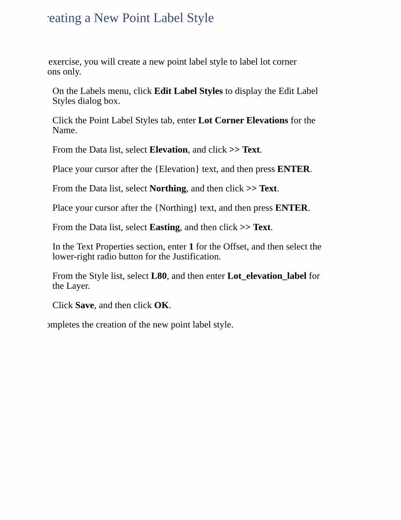
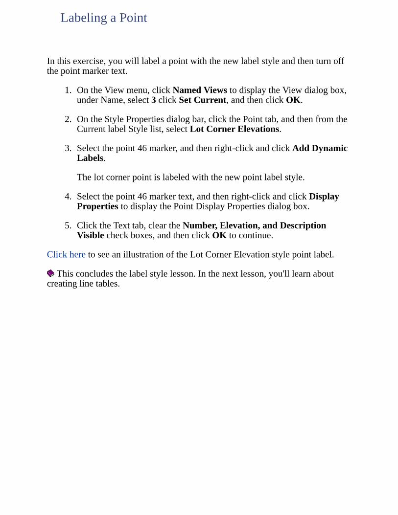
Inthisexercise,youwilllabelapointwiththenewlabelstyleandthenturnoffthepointmarkertext.
1. OntheViewmenu,clickNamedViewstodisplaytheViewdialogbox,underName,select3clickSetCurrent,andthenclickOK.
2. OntheStylePropertiesdialogbar,clickthePointtab,andthenfromtheCurrentlabelStylelist,selectLotCornerElevations.
3. Selectthepoint46marker,andthenright-clickandclickAddDynamicLabels.
Thelotcornerpointislabeledwiththenewpointlabelstyle.
4. Selectthepoint46markertext,andthenright-clickandclickDisplayPropertiestodisplaythePointDisplayPropertiesdialogbox.
5. ClicktheTexttab,cleartheNumber,Elevation,andDescriptionVisiblecheckboxes,andthenclickOKtocontinue.
ClickheretoseeanillustrationoftheLotCornerElevationstylepointlabel.
Thisconcludesthelabelstylelesson.Inthenextlesson,you'lllearnaboutcreatinglinetables.
LabelingaPoint
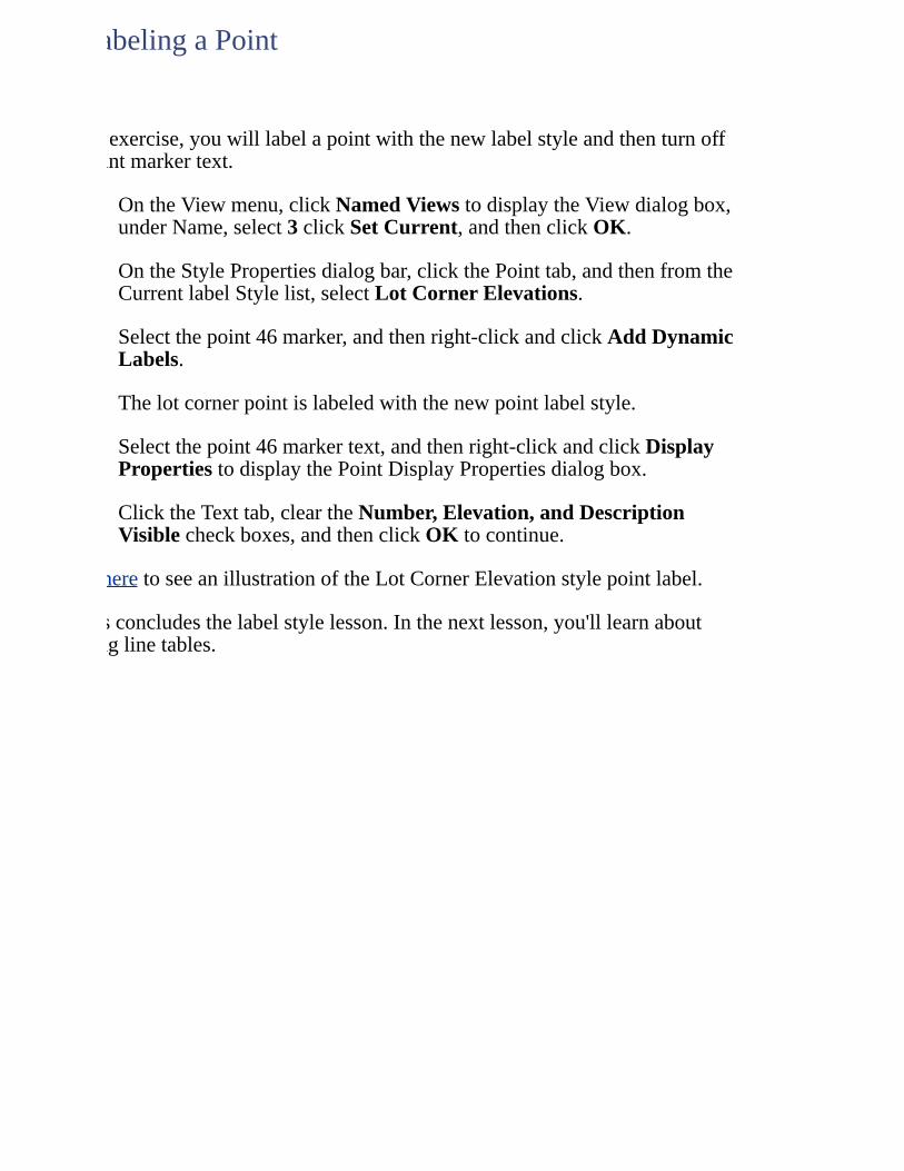
Youmustaddtaglabelstoline,curve,andspiralobjectsbeforeyoucancreatetablesfromtheseobjects.Oncetaglabelshavebeenassignedtotheobjects,youcangeneratetablesthatdisplayobjectdata(objecttables).
Toworkthroughthislessonfollowthesesteps
1. StartAutoCADLandDesktopifyouhavenotalreadydoneso.
2. OntheFilemenu,clickOpentodisplaytheOpenDrawing:ProjectBaseddialogbox.
Thedefaultlocationfolderforprojectfilesisc:\LandProjects<VersionNumber>.Ifyouoptedtoinstallthesefilesinanotherlocationinstead,specifytheappropriateprojectpath.
3. FromtheProjectNamelist,selectTutorial1,fromtheSelectProjectDrawinglist,selectLesson-11.dwg,thenclickOK.
4. OntheProjectsmenu,clickWorkspacestodisplaytheWorkspacestoolbar.Inthelist,selectLandDesktoptodisplaytheLandDesktopmenus.
WorkingthroughtheselessonswillresultinalterationoftheTutorialprojectfiles.Backupcopiesoftheseprojectfilescanbefoundinthec:\ProgramFiles\AutoCADLandDesktop<VersionNumber>\Landtutfolder.
Ifthislessonhasbeenpreviouslyrun,copytheseunalteredprojectfilestothe\LandProjects<VersionNumber>folderwhenstartinganewtutorialsessiontoensurethatthesequenceoutlinedineachlessoncanbefollowedproperly.
LESSON11:CreatingTagLabelsandObjectTables
Inthisexercise,youwillcreateanewtagstylebyspecifyingtagparametersforlinesandcurves.
1. OntheLabelsmenu,clickEditTagStylestodisplaytheEditTagLabelStylesdialogbox.
2. OntheLineLabelStylestab,enterBoundaryTagsforXYZCofortheName.
3. IntheTextPropertiessection,fromtheStylelist,selectL200,thenenterBoundary_tagsfortheLayer.
4. ClicktheCurveLabelStylestab,thenenterBoundaryTagsforXYZCofortheName.
5. IntheTextPropertiessection,fromtheStylelist,selectL200,thenenterBoundary_tagsfortheLayer.
6. ClickSave,thenclickOKtocontinue.
Thiscompletesthecreationofanewtagstyle.
CreatingaNewTagStyle
Inthisexercise,youwillisolatetheBoundarylayerandlabeltheboundarypolylinewiththenewtagstyle.
1. Onthecommandline,enterLAI,selectapointononeoftheblueboundarypolylines,pressENTERtodisplaytheLayer(s)toisolatedialogbox,thenclickOK.
2. OntheLabelsmenu,clickShowDialogBartodisplaytheStylePropertiesdialogbar.
3. ClicktheLabelicontotoggletotheTagicon,thenontheLinetab,fromtheCurrentTagStylelist,selectBoundaryTagsforXYZCo.
4. ClicktheCurvetab,andfromtheCurrentTagStylelist,selectBoundaryTagsforXYZCo.
5. OntheLabelsmenu,clickAddTagLabels,selectbothoftheblueboundarypolylines,thenpressENTER.
6. OntheViewmenu,clickNamedViewstodisplaytheViewdialogbox,underName,select2,clickSetCurrent,thenclickOK.
Clickheretoseeanillustrationofboundarylinetags.
Theboundaryislabeledwithtagsforeachsegmentofthepolyline.
LabelingObjectswithTags
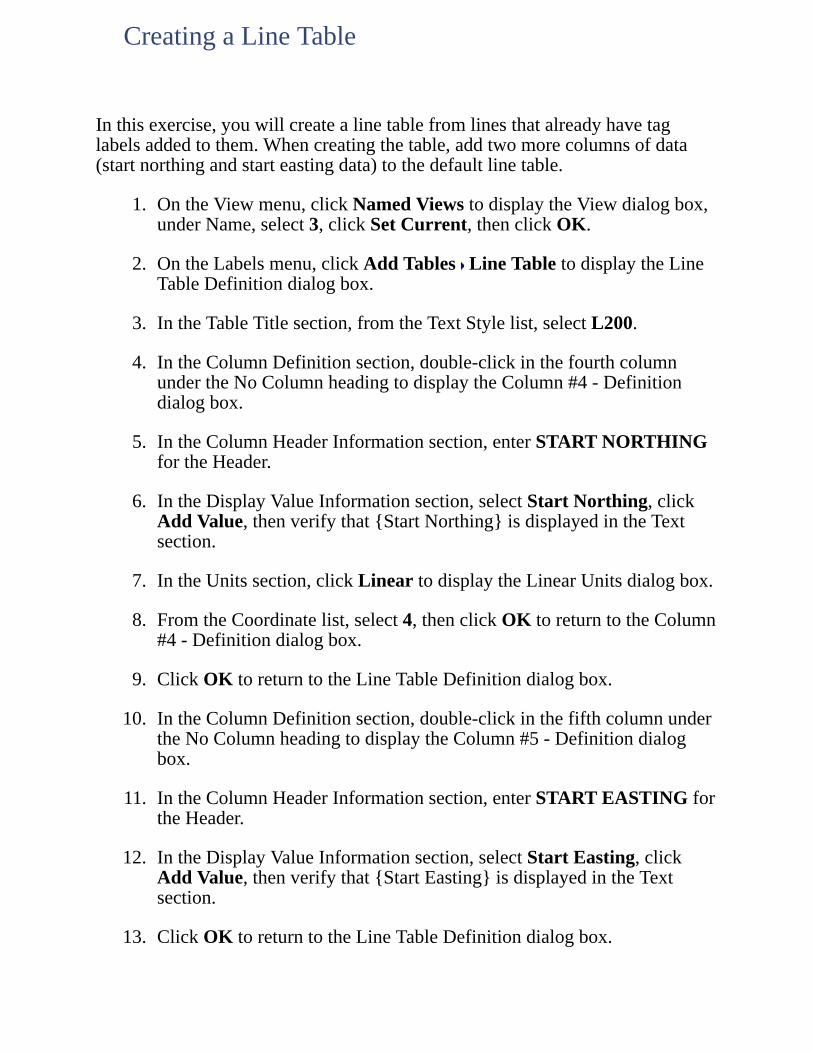
Inthisexercise,youwillcreatealinetablefromlinesthatalreadyhavetaglabelsaddedtothem.Whencreatingthetable,addtwomorecolumnsofdata(startnorthingandstarteastingdata)tothedefaultlinetable.
1. OntheViewmenu,clickNamedViewstodisplaytheViewdialogbox,underName,select3,clickSetCurrent,thenclickOK.
2. OntheLabelsmenu,clickAddTables LineTabletodisplaytheLineTableDefinitiondialogbox.
3. IntheTableTitlesection,fromtheTextStylelist,selectL200.
4. IntheColumnDefinitionsection,double-clickinthefourthcolumnundertheNoColumnheadingtodisplaytheColumn#4-Definitiondialogbox.
5. IntheColumnHeaderInformationsection,enterSTARTNORTHINGfortheHeader.
6. IntheDisplayValueInformationsection,selectStartNorthing,clickAddValue,thenverifythat{StartNorthing}isdisplayedintheTextsection.
7. IntheUnitssection,clickLineartodisplaytheLinearUnitsdialogbox.
8. FromtheCoordinatelist,select4,thenclickOKtoreturntotheColumn#4-Definitiondialogbox.
9. ClickOKtoreturntotheLineTableDefinitiondialogbox.
10. IntheColumnDefinitionsection,double-clickinthefifthcolumnundertheNoColumnheadingtodisplaytheColumn#5-Definitiondialogbox.
11. IntheColumnHeaderInformationsection,enterSTARTEASTINGfortheHeader.
12. IntheDisplayValueInformationsection,selectStartEasting,clickAddValue,thenverifythat{StartEasting}isdisplayedintheTextsection.
13. ClickOKtoreturntotheLineTableDefinitiondialogbox.
CreatingaLineTable
14. ClickOKontheLineTableDefinitiondialogbox.
15. Clickonthelocationinthedrawingwhereyouwantthetableplaced.Theupper-leftcornerofthetableisinsertedwhereyouclicked.
16. Youmayneedtozoomintoseethelinetable.
Clickheretoseeanillustrationofthelinetable.
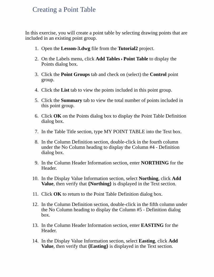
Inthisexercise,youwillcreateapointtablebyselectingdrawingpointsthatareincludedinanexistingpointgroup.
1. OpentheLesson-3.dwgfilefromtheTutorial2project.
2. OntheLabelsmenu,clickAddTables PointTabletodisplaythePointsdialogbox.
3. ClickthePointGroupstabandcheckon(select)theControlpointgroup.
4. ClicktheListtabtoviewthepointsincludedinthispointgroup.
5. ClicktheSummarytabtoviewthetotalnumberofpointsincludedinthispointgroup.
6. ClickOKonthePointsdialogboxtodisplaythePointTableDefinitiondialogbox.
7. IntheTableTitlesection,typeMYPOINTTABLEintotheTextbox.
8. IntheColumnDefinitionsection,double-clickinthefourthcolumnundertheNoColumnheadingtodisplaytheColumn#4-Definitiondialogbox.
9. IntheColumnHeaderInformationsection,enterNORTHINGfortheHeader.
10. IntheDisplayValueInformationsection,selectNorthing,clickAddValue,thenverifythat{Northing}isdisplayedintheTextsection.
11. ClickOKtoreturntothePointTableDefinitiondialogbox.
12. IntheColumnDefinitionsection,double-clickinthefifthcolumnundertheNoColumnheadingtodisplaytheColumn#5-Definitiondialogbox.
13. IntheColumnHeaderInformationsection,enterEASTINGfortheHeader.
14. IntheDisplayValueInformationsection,selectEasting,clickAddValue,thenverifythat{Easting}isdisplayedintheTextsection.
CreatingaPointTable

15. ClickOKtoreturntothePointTableDefinitiondialogbox.
16. ClickOKonthePointTableDefinitiondialogbox.
17. Clickonthelocationinthedrawingwhereyouwantthetableplaced.Theupper-leftcornerofthetableisinsertedwhereyouclicked.
18. Youmayneedtozoomintoseethetable.
Points247and758displayinthetablebecausetheyexistinthedrawing.Pointsthatexistinthepointsdatabasebutnotinthedrawingdonotdisplayinthetable.
TheRe-DrawTablecommandletsyouautomaticallyupdatetheinformationdisplayedinaline,curve,orspiralobjecttable.Forexample,ifyoucreatedalinetablethatdisplayedinformationon20lineobjects,andthenyoudeletedsomeofthoselinesfromyourdrawing,theinformationintheobjecttablewouldnotchange.However,youcanusetheRe-DrawTablecommandtoautomaticallyupdatethetablesothatitdisplayscurrentobjectdata.
1. ClosethecurrentdrawingandprojectthenopentheTutorial1projectandtheLesson-11.dwgfile.
2. Inapreviouslesson,youcreatedalinetable.Clickheretoseeanillustrationofthatlinetable.Ifyoudonothavealinetableonthecurrentdrawing,createoneusingthestepsintheCreatingaLineTablelesson.
3. Inthedrawing,selectanythreelinesfromthedrawinganddeletethem.Noticethatthelinetablestilldisplaysinformationonthelinesthatyoujustdeletedfromthedrawing.
4. FromtheLabelsmenu,selectEditTables Re-DrawTable.
5. Clickonanytextinthelinetable,thenpressENTER.Noticethatthetableautomaticallyupdates,removingtherowsofdataforlinesthatnolongerexistinthedrawing.
TheRe-DrawTablecommandupdatesallobjectinformationdisplayedinthetable.Forexample,ifnorthingandeastingdatachangedforobjectsdisplayedinthetable,Re-Drawautomaticallyupdatestheinformationdisplayedinthetable.
Updating(Re-drawing)anObjectTable
ThisexerciseillustratesdifferencesbetweenobjecttablesthathavetheCreateTableObjectoptionontheTableDefinitiondialogselected,andobjecttablesthatdonothavethisoptionselected.
1. OpentheTutorial1projectandtheLesson-11.dwgfile.
2. Createanewlinetable,makingsuretheCreateTableObjectoptionontheLineTableDefinitiondialogboxisnotselected,andtypingNOTTABLEOBJECTintotheTableTitleTextbox.Insertthislinetableontoyourdrawing.
3. Createanotherlinetable,thistimeselectingtheCreateTableObjectoptionontheLineTableDefinitiondialogbox,andtypingISTABLEOBJECTintotheTableTitleTextbox.
4. Insertthistablenexttothefirstone,sotheyareeitherside-by-side,oroneabovetheother.
5. IntheNOTTABLEOBJECTtable,selectanygridlineinthetable.Notethatonlythelineyouclickedonisselected,nottheentiretable.Ifyoumovethisline,onlythatlinesmoves.
6. IntheISTABLEOBJECTtable,selectanygridlineinthetable.Notethattheentiretableisselected,notjustthelineyouclickedon.Ifyoumovetheselectedline,thetabledoesnotmove.
7. IntheISTABLEOBJECTtable,clicktheupperleftcornerhandle.Theentiretableisselected.Tomovethistypeoftable,clickontheupperleftcornerhandleanddragthetabletoanewlocation.
8. IntheNOTTABLEOBJECTtable,selecttheentiretableusingawindoworcrossingselection.Tomovethistypeoftable,clickonanypartofthetable,whiletheentiretableisselected,andmoveittoanewlocation.
Thisconcludestheobjecttablelesson.Inthenextlesson,you'lllearnabouttheTerrainModelExplorer.
UnderstandingTableObjects
UsetheTerrainModelExplorertocreatedigitalterrainmodels(DTMs)fromanycombinationofpoint,contour,breakline,andsurfaceboundarydata.
Toworkthroughthislessonfollowthesesteps
1. 1StartAutoCADLandDesktopifyouhavenotalreadydoneso.
2. 2OntheFilemenu,clickOpentodisplaytheOpenDrawing:ProjectBaseddialogbox.
Thedefaultlocationfolderforprojectfilesisc:\LandProjects<VersionNumber>.Ifyouoptedtoinstallthesefilesinanotherlocationinstead,specifytheappropriateprojectpath.
3. 3FromtheProjectNamelist,selectTUTORIAL1,fromtheSelectProjectDrawinglist,selectLesson-12.dwg,andthenclickOK.
4. 4OntheProjectsmenu,clickWorkspacestodisplaytheWorkspacestoolbar.Inthelist,selectLandDesktoptodisplaytheLandDesktopmenus.
Workingthroughtheselessonswillresultinalterationoftheprojectfiles.Backupcopiesoftheseprojectfilescanbefoundinthec:\ProgramFiles\AutoCADLandDesktop<VersionNumber>\Landtutfolder.
Ifthislessonhasbeenpreviouslyrun,copytheseunalteredprojectfilestothe\LandProjects<VersionNumber>folderwhenstartinganewtutorialsessiontoensurethatthesequenceoutlinedineachlessoncanbefollowedproperly.
LESSON12:WorkingwiththeTerrainModelExplorer
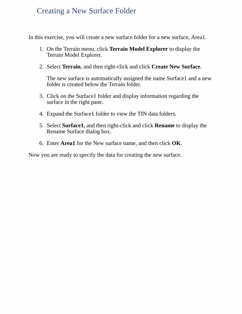
Inthisexercise,youwillcreateanewsurfacefolderforanewsurface,Area1.
1. OntheTerrainmenu,clickTerrainModelExplorertodisplaytheTerrainModelExplorer.
2. SelectTerrain,andthenright-clickandclickCreateNewSurface.
ThenewsurfaceisautomaticallyassignedthenameSurface1andanewfolderiscreatedbelowtheTerrainfolder.
3. ClickontheSurface1folderanddisplayinformationregardingthesurfaceintherightpane.
4. ExpandtheSurface1foldertoviewtheTINdatafolders.
5. SelectSurface1,andthenright-clickandclickRenametodisplaytheRenameSurfacedialogbox.
6. EnterArea1fortheNewsurfacename,andthenclickOK.
Nowyouarereadytospecifythedataforcreatingthenewsurface.
CreatingaNewSurfaceFolder
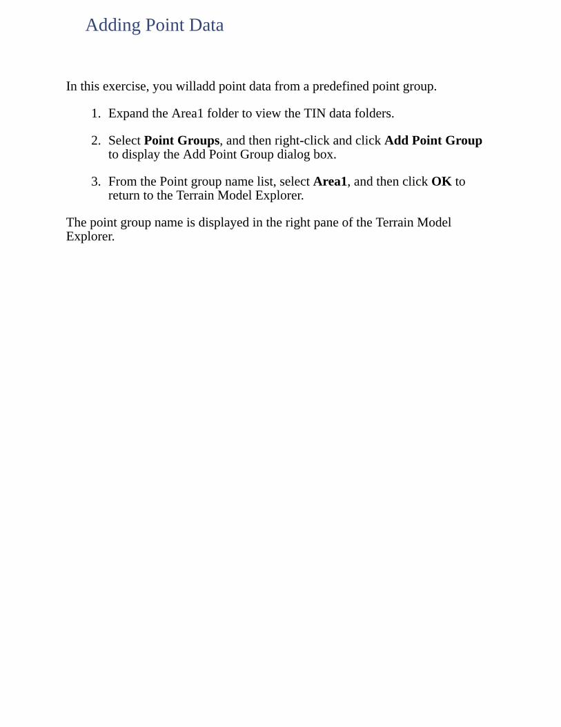
Inthisexercise,youwilladdpointdatafromapredefinedpointgroup.
1. ExpandtheArea1foldertoviewtheTINdatafolders.
2. SelectPointGroups,andthenright-clickandclickAddPointGrouptodisplaytheAddPointGroupdialogbox.
3. FromthePointgroupnamelist,selectArea1,andthenclickOKtoreturntotheTerrainModelExplorer.
ThepointgroupnameisdisplayedintherightpaneoftheTerrainModelExplorer.
AddingPointData
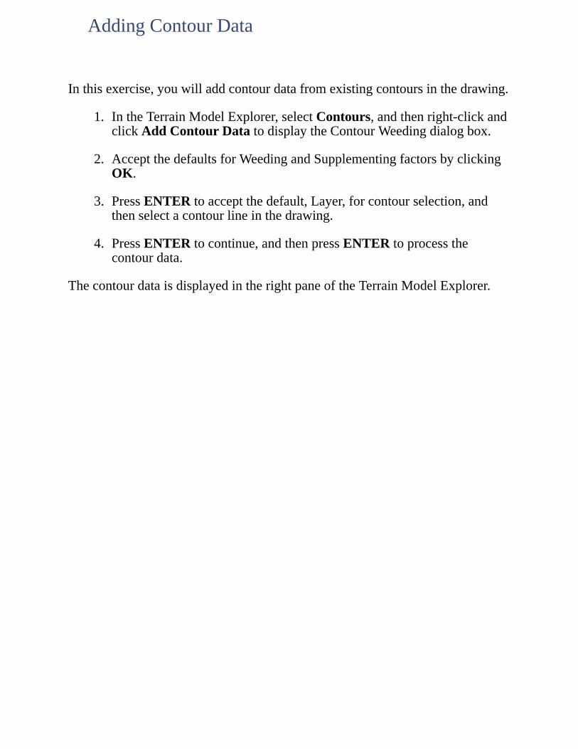
Inthisexercise,youwilladdcontourdatafromexistingcontoursinthedrawing.
1. IntheTerrainModelExplorer,selectContours,andthenright-clickandclickAddContourDatatodisplaytheContourWeedingdialogbox.
2. AcceptthedefaultsforWeedingandSupplementingfactorsbyclickingOK.
3. PressENTERtoacceptthedefault,Layer,forcontourselection,andthenselectacontourlineinthedrawing.
4. PressENTERtocontinue,andthenpressENTERtoprocessthecontourdata.
ThecontourdataisdisplayedintherightpaneoftheTerrainModelExplorer.
AddingContourData
Inthisexercise,youwilladdbreaklinedatafromexistingpointsand2Dand3Dpolylinesinthedrawing.Firstcreateabreaklinefrompointstodefinethestreambedcenterline.
1. MovetheTerrainModelExplorertothesideofyourscreen.
2. OntheViewmenu,clickNamedViewstodisplaytheViewdialogbox.UnderName,select2,clickSetCurrent,andthenclickOK.
3. EnterLAI,selectoneofthestreambedpoints(thecyanXsidentifiedwiththedescriptionStrmBed),andthenpressENTERtodisplaytheLayer(s)toisolatedialogbox.
4. VerifythelayerSTREAM_PNTSisdisplayedintheItembox,andclickOKtoisolatethestreambedlayer.
5. OntheTerrainModelExplorerselectBreaklines,andthenright-clickandclickDefinebyPoint.
6. Selectthebottomstreambedpoint,andselecttheremainingstreambedpointssequentiallyfrombottomtotop,andthenpressENTERwhenyouhavefinishedselectingthepoints.
7. EnterStreambedfortheDescription.
8. PressENTERtodisplaytheTerrainBreaklinesdialogbox,andthenclickNotocontinueandprocessthebreaklinedata.
Thebreaklineisgeneratedwitheachstreambedpointasavertex.
Clickheretoseeanillustrationofthestreambedbreakline.
ThebreaklinepointdataisdisplayedintherightpaneoftheTerrainModelExplorer.
AddingBreaklineDatafromPoints
Inthisexercise,youwilldefinebreaklinesfromexisting3Dpolylinesthatrepresentexistingroadwayedgeofpavement.
1. Onthecommandline,enterLOAtoturnallofthelayersinthedrawingbackon.
2. OntheViewmenu,clickNamedViewstodisplaytheViewdialogbox.UnderName,select3,clickSetCurrent,andthenclickOK.
3. EnterLAI,selectoneoftheredexistingroadwayEOP3Dpolylines,andthenpressENTERtodisplaytheLayer(s)toisolatedialogbox.
4. VerifythattheEOP_3DlayerisselectedandclickOKtoisolatetheexistingroadwayEOPlayer.
5. OntheViewmenu,clickNamedViewstodisplaytheViewdialogbox.UnderName,select1,clickSetCurrent,andthenclickOK.
6. OntheTerrainModelExplorerselectBreaklines,andthenright-clickandclickDefinebyPolyline.
7. EnterExisting_Road_EOPfortheDescription,andthenuseacrossingboxtoselecttheexistingroadwayEOP3Dpolylines.Makesureyouselectallofthepolylines.
8. PressENTERtodisplaytheTerrainBreaklinesdialogbox,clickNotocontinueandprocessthebreaklinedata.
The3DpolylinebreaklinedataisdisplayedintherightpaneoftheTerrainModelExplorer.
AddingBreaklineDatafrom3DPolylines
Inthisexercise,youwilldefinebreaklinesfromexisting2Dpolylinesthathavebeendrawnbetweenexistingroadwayedgeofpavement,ditch,andrailwaybedpoints.
1. Onthecommandline,enterLOAtoturnallofthelayersinthedrawingbackon.
2. EnterLAI,andthenpressENTERtwicetodisplaytheLayer(s)toisolatedialogbox.
3. FromtheLayerslist,select2D_Breaklines,andthenclickOKtoisolatetheexistingroad2Dpolylines.
4. OntheTerrainModelExplorer,selectBreaklines,andthenright-clickandclickProximitybyPolylines.
5. EnterMisc_TopofortheDescription,andthenuseacrossingboxtoselecttheexisting2Dpolylines.
6. PressENTERtodisplaytheTerrainBreaklinesdialogbox,andthenclickNotocontinue.
7. Asadditionalmessagedialogboxesaredisplayed,clickYestocontinueandprocessthebreaklinedata.
The2DpolylinebreaklinedataisdisplayedintherightpaneoftheTerrainModelExplorer.
AddingBreaklineDatafrom2DPolylines
Inthisexercise,youwilladdsurfaceboundarydatafromanexistingsurfaceboundaryinthedrawing.
1. Onthecommandline,enterLOAtoturnallofthelayersinthedrawingbackon.
2. OntheTerrainModelExplorer,selectBoundaries,andthenright-clickandclickAddBoundaryDefinition.
3. Selectthewhitesurfaceboundarypolyline,andthenenterArea1fortheBoundaryname.
4. PressENTERtoacceptthedefaultboundarytype,Outer.
TheOuteroptionlimitstheextentsofthesurfacetotheareainsidetheselectedsurfaceboundarypolyline.
5. EnterNoformakingbreaklinesalongedges,andthenpressENTERtoendthecommand.
Whenbreaklinesarenotmadealongtheedge,onlydatainsideinsideofthepolylineboundaryisconsideredwhencreatingthesurface.
ThesurfaceboundarydataisdisplayedintherightpaneoftheTerrainModelExplorer.
AddingSurfaceBoundaryData
Inthisexercise,youwillbuildthesurfaceusingpoint,contour,breakline,andsurfaceboundarydata.
1. OntheTerrainModelExplorer,intheleftpane,selectArea1,andthenright-clickandclickBuildtodisplaytheBuildArea1dialogbox.
2. EnterArea1fortheDescription.
3. IntheSurfaceDataOptionssection,cleartheUsepointfiledatacheckboxandselecttheMinimizeflattrianglesresultingfromcontourdatacheckbox.
4. ClickOKtoprocessallofthesurfacedataandbuildthesurface.
5. AstheBuildProgressdialogboxisdisplayed,clickOKtoendthecommand.
ThesurfacedataforsurfaceArea1isdisplayedintherightpaneoftheTerrainModelExplorer.Younowhaveasurfacemodelgeneratedfrompoint,contour,andbreaklinedatarepresentingactualterrainconditions.
6. WhenyouhavefinshedreviewingthedataintheTerrainModelExplorer,closeit.
ThisconcludestheTerrainModelExplorerlesson.Inthenextlesson,you'lllearnabouteditingsurfaces.
BuildingaSurface
Asurfacemodelcreatedbythetriangulationprocessisonlyasaccurateasthedatausedtobuildit.Sparseelevationaldataandlackofbreaklinecontrolyieldsambiguousresultsatbest.Evenwithextensiveelevationaldatainthesurfacefile,itisimportanttoverifythatthesurfacemodelisanaccuraterepresentationofthesiteconditions.
Inthislesson,afewareasarepinpointedforsurfaceediting.However,theentiresurfacerequiresadditionaleditingthatisnotcoveredinthislesson.
Toworkthroughthislessonfollowthesesteps
1. StartAutoCADLandDesktopifyouhavenotalreadydoneso.
2. OntheFilemenu,clickOpentodisplaytheOpenDrawing:ProjectBaseddialogbox.
Thedefaultlocationfolderforprojectfilesisc:\LandProjects<VersionNumber>.Ifyouoptedtoinstallthesefilesinanotherlocationinstead,specifytheappropriateprojectpath.
3. FromtheProjectNamelist,selectTUTORIAL1,fromtheSelectProjectDrawinglist,selectLesson-13.dwg,andthenclickOK.
4. OntheProjectsmenu,clickWorkspacestodisplaytheWorkspacestoolbar.Inthelist,selectLandDesktoptodisplaytheLandDesktopmenus.
Workingthroughtheselessonswillresultinalterationoftheprojectfiles.Backupcopiesoftheseprojectfilescanbefoundinthec:\ProgramFiles\AutoCADLandDesktop<VersionNumber>\Landtutfolder.
Ifthislessonhasbeenpreviouslyrun,copytheseunalteredprojectfilestothe\LandProjects<VersionNumber>folderwhenstartinganewtutorialsessiontoensurethatthesequenceoutlinedineachlessoncanbefollowedproperly.
LESSON13:EditingSurfaces
First-handknowledgeofthesiteisindispensableforidentifyingproblemswiththesurfacemodel,andcomparingyourdrawingtositephotographsisusefulevenifyouhaveaccesstothesite.
Onewaytoidentifytriangulationproblemsistolookatcontoursandseewherefeaturessuchasridgelinesorstreambedsareimproperlyrepresented.Unnecessarilyjaggedcontourscanalsobeindicativeoftriangulationproblems.Asecondwaytoidentifytriangulationproblemsistolookatsectionscutthroughcriticalareastoverifyexpectedsurfacebehavior.
1. OntheViewmenu,clickNamedViewstodisplaytheViewdialogbox,underName,select2,clickSetCurrent,andthenclickOK.
2. OntheTerrainmenu,clickSetCurrentSurfacetodisplaytheSelectSurfacedialogbox,fromtheSelectionlist,selectArea1b,andthenclickOK.
Toseethetriangulationpatternthatcausesproblemswithoutaddinganyobjectstothedrawing,generateaQuickView.
3. OntheTerrainmenu,clickSurfaceDisplay QuickView.
QuickViewentitiesaredrawnwithtemporaryvectorsandcannotbeedited.
Inthecircledarea,theTINlinestriangulatebetweencontoursatthesameelevation,thuscreatingaflatarea.Inmostcases,flatsurfaceslikethisareminimized.Occasionally,manualeditingisnecessarytocorrectthesesituationswhentheyoccur.Also,intheaccompanyingexistinggroundcrosssection,theslopetotheleftisflat,andthendropsoffsteeply.Thisdoesnotreflecttheactualslopecondition.
4Onthecommandline,enterREDRAWtoerasetheQuickViewtemporaryvectors.
IdentifyingTriangulationProblems
Pointobjectscanbeaddedtotheoriginaldatausedtobuildthesurfaceandthesurfacecanberebuiltatanytimewiththisinformation.However,toavoidhavingtorebuildthesurface,surfacepointscanbeadded.
First,importthesurfacetriangulationlinesas3Dlines.
1. OntheTerrainmenu,clickEditSurface Import3DLines.
2. PressENTERtoacceptthedefault,Yes,toerasetheoldsurfaceview.
Sincethecontourlinesinthespecificareaareatanelevationof122m,addasurfacepointmidwaybetweenthecontourlines(thecenterpointofcircle1)atanelevationof121.5m.
3. OntheTerrainmenu,clickEditSurface AddPoint.
4. UseaCenterOsnaptoselectthecenterofthesmallreferencecircle1,enter121.5mfortheElevation,andthenpressENTER.
Thesurfacepointwasadded,withthetriangulationadjustedautomatically,butsomeflattrianglesremain.
Clickheretoseeanillustrationofhowtheareawithinthecirclewasretriangulated.
AddingPointstotheSurface
Inthisexercise,youwilladdtwolinestocorrecttheflattriangulation.Addthefirstbetweenpoints1and2.
1. OntheTerrainmenu,clickEditSurface AddLine.
2. UseEndpointOsnapstoselecttheTINvertexpointinsidecircle1fortheFrompointandtheTINvertexpointinsidecircle2fortheTopoint,andthenpressENTER.
Thelineisaddedbetweenpoints1and2andthattriangulationlinescrossedbythenewlineareautomaticallydeleted.
ClickheretoseeanillustrationoftheaddedTINLine.
ExtraneousTINlines,oftenlongsliversthatappearontheoutsideedgesofsurfacesshouldbedeleted.Deletetheslivertotheleftofpoint2.
3. OntheViewmenu,clickNamedViewstodisplaytheViewdialogbox.UnderName,select2B,clickSetCurrent,andthenclickOK.
4. OntheTerrainmenu,clickEditSurface DeleteLine.
5. 5SelectthesliverTINline,andthenpressENTER.
ThesliverTINlineisdeleted.
AddingandDeletingTINLines
FlippingTINfacesisanotherwaytocorrecttriangulationproblems.
1. OntheViewmenu,clickNamedViewstodisplaytheViewdialogbox,underName,select3,clickSetCurrent,andthenclickOK.
Thecyancontourlinesthatoccurroughlybetweenpoints3and4arejagged.CorrectthissituationbyflippingtheTINfacebetweenpoints3and4.
2. OntheTerrainmenu,clickEditSurface FlipFace.
3. SelecttheTINlinethatislocatedbetweenpoints3and4,andthenpressENTER.
ClickheretoseeanillustrationoftheflippedTINline.
Recreatethecontourstoviewthetriangulationchange.
4. OntheTerrainmenu,clickCreateContourstodisplaytheCreateContoursdialogbox.
5. AcceptthedefaultvaluesdisplayedinthisdialogboxbyclickingOK.
6. PressENTERtoacceptthedefault,Yes,toeraseoldcontours.
Thecontoursarerecreatedbasedonthecorrecttriangulation,withasmootherappearanceratherthanajaggedappearance.
Clickheretoseeanillustrationofrecreatedcontours.
FlippingTINFaces
Afterthesurfacehasbeenbuiltandedited,furtherreviewofthesurfacesometimesidentifiestheneedforadditionalbreaklines.Incorporatingadditionalsurfacedatalikebreaklines,requiresthatyourebuildthesurface.ThisistrueregardinganyadditionalsurfacedatanotaddedoralteredbytheSurfaceEditingcommands.
Surfaceedithistorycanberecordedandaddedtoafile,andthenreappliedtoasurfacewhenitisrebuilt.RebuildingasurfacewiththeEditHistoryoptiontoggledonwillreturnittoitsoriginalstate,beforeeditingoccurred.
1. OntheTerrainmenu,clickTerrainModelExplorertodisplaytheTerrainModelExplorer.
2. SelectArea1b,andthenright-clickandclickBuildtodisplaytheSurfaceModifieddialogbox.
3. ClickYestoacknowledgetheSurfaceModifieddialogboxanddisplaytheBuildArea1bdialogbox.
4. EnterArea1bfortheDescription,andthenintheSurfaceDataOptionssection,verifythattheUsepointgroupdata,Usebreaklinedata,andUsecontourdatacheckboxesareselected.
5. SelecttheMinimizeflattrianglesresultingfromcontourdataandApplyEditHistorycheckboxes,andthenclickOK.
Thesurfacedataisreprocessedandthesurfaceisrebuilt.
6. Asamessagedialogboxisdisplayed,clickOKtocontinue,andthenclosetheTerrainModelExplorer.
7. OntheTerrainmenu,clickSurfaceDisplay QuickView.
Thesurfaceeditspreviouslyperformedhavebeenreappliedtothesurface.
Thisconcludesthesurfaceeditinglesson.Inthenextlesson,you'lllearnaboutcreatingcontours.
ApplyingSurfaceEditHistory
Contourscanbecreatedaseitherpolylinesorcontourobjects.Usingcontourobjectsresultsinasmallerdrawingfilesizeandallowsforgreaterflexibilityinlabeling.
Toworkthroughthislessonfollowthesesteps
1. StartAutoCADLandDesktopifyouhavenotalreadydoneso.
2. OntheFilemenu,clickOpentodisplaytheOpenDrawing:ProjectBaseddialogbox.
Thedefaultlocationfolderforprojectfilesisc:\LandProjects<VersionNumber>.Ifyouoptedtoinstallthesefilesinanotherlocationinstead,specifytheappropriateprojectpath.
3. FromtheProjectNamelist,selectTUTORIAL1,fromtheSelectProjectDrawinglist,selectLesson-14.dwg,andthenclickOK.
4. OntheProjectsmenu,clickWorkspacestodisplaytheWorkspacestoolbar.Inthelist,selectLandDesktoptodisplaytheLandDesktopmenus.
Workingthroughtheselessonswillresultinalterationoftheprojectfiles.Backupcopiesoftheseprojectfilescanbefoundinthec:\ProgramFiles\AutoCADLandDesktop<VersionNumber>\Landtutfolder.
Ifthislessonhasbeenpreviouslyrun,copytheseunalteredprojectfilestothe\LandProjects<VersionNumber>folderwhenstartinganewtutorialsessiontoensurethatthesequenceoutlinedineachlessoncanbefollowedproperly.
LESSON14:CreatingContours
Createcontoursfromasurfacethatexistsintheprojectdatabaseandbasedonthecurrentcontourstyle,Standard,thatissetasthedefaultintheContourStyleManagerdialogbox.Createmajorcontoursat5mintervalsandminorcontoursat1mintervals.
1. OntheTerrainmenu,clickSetCurrentSurfacetodisplaytheSelectSurfacedialogbox,fromtheSelectionlist,selectAREA1C,andthenclickOK.
2. OntheTerrainmenu,clickCreateContourstodisplaytheCreateContoursdialogbox.
3. IntheIntervalssection,selectBothMinorandMajor.
4. FromtheMinorIntervallist,select1m,andthenverifythatCONT-MNRistheminorintervalLayer.
5. FromtheMajorIntervallist,select5m,andthenverifythatCONR-MJRisthemajorintervalLayer.
6. InthePropertiessection,verifythatContourObjectsisselected,andthenclickOKtocreatethecontours.
7. PressENTERtoacceptthedefault,Yes,toeraseoldcontours.
Thecontoursarecreatedat1mminorintervalsand5mmajorintervals.
ClickheretoseeanillustrationofthecountoursforthesurfaceArea1C.
CreatingContours
Inthisexercise,youwillchangecontoursstylepropertiesintheContourStyleManagerdialogbox.Edittheappearanceofcontoursandhowlabelsappearonthecontours.Assigndifferentcontourstylepropertiestoeithersinglecontoursorallofthecontoursinthedrawing.
1. OntheTerrainmenu,clickContourStyleManagertodisplaytheContourStyleManagerdialogbox.
2. ClicktheManageStylestab.IntheContourStylesinDrawinglist,enterSMOOTH,andthenclickAdd.
Atthispoint,thenewcontourstylecaneitherbesavedasastyleaccessiblebyallprojectsorjustthecurrentdrawing.
3. ClicktheContourAppearancetabandverifythattheCurrentStyleisSMOOTH.
4. IntheContourDisplaysection,selectContoursandGrips,andthenintheSmoothingOptionssection,selectAddVerticesandsetthesliderto8.
5. ClicktheTextStyletabandintheTextPropertiessection,fromtheStylelist,select2MM.SetthePrecisionto0.
6. SelecttheColorboxtodisplaytheSelectColordialogbox.FromtheStandardColorsbarselectcyan(lightblue),andthenclickOKtoreturntotheContourStyleManagerdialogbox.
7. FromtheSuffixlist,selectm.
8. ClicktheLabelPositiontab.IntheOrientationsection,verifythatOnContourisselectedandtheBreakContourForLabelcheckboxisselected.
9. IntheReadabilitysection,selectLabelPositiveSlopeandintheBorderAroundLabelsection,selectRectangular,andthenclickOK.
Younowhaveanewcontourstyletoapplytocontoursinyourdrawing.
CreatingaNewContourStyle

Inthisexercise,youwillapplythenewSMOOTHcontourstyletoallofthecontoursinthedrawing.
1. ClicktheLayersicon,makelayerCONT-MJRthecurrentlayer,andfreezelayer0.
2. Selectallofthecontoursinthedrawingwithacrossingselectionbox.
3. Right-clickandclickContourPropertiestodisplaytheContourStyleManagerdialogbox.
4. ClicktheManageStylestab,fromContourStylesinDrawinglist,selectSMOOTH,andthenclickOK.
Allofthecontoursinthedrawingnowappearwiththenewcontourstyle,SMOOTH.
Clickheretoseeanillustrationofthecontourswiththenewcontourstyleapplied.
ApplyingaNewContourStyle
Inthisexercise,youwillassignelevationlabelstothecontoursbasedonthelabelstylesetintheContourStyleManagerdialogbox.
1. OntheViewmenu,clickNamedViewstodisplaytheViewdialogbox.UnderName,select1,clickSetCurrent,andthenclickOK.
2. OntheTerrainmenu,clickContourLabels GroupInteriortodisplaytheContourLabels-Incrementsdialogbox.
3. Enter2mfortheElevationIncrement,cleartheAddmultipleinteriorlabelsalongeachcontourcheckbox,andthenclickOK.
Dragalineacrossthecontourstobelabeled.
4. Selectapointnearthelower-leftcornerofthecurrentviewfortheStartpoint,andthenselectapointneartheupper-rightcornerfortheEndpoint.PressENTERtoendthecommand.
Thecontoursarelabeledevery2mwitharectangularboxborderaroundtheelevationtext.Thecontourappearstobebrokenaroundthecontourlabelbox,butisactuallystillintactasacontinuouscontourline.
Clickheretoseeanillustrationofthecontourslabeledat2mincrements.
Usethefollowingstepstorepositionacontourlabel.
5. Selectacontourtodisplayitsgrips,selectthegripatthecenterofthecontourlabel,andthenslidethecontourlabelalongthecontour.
6. Clicktofixthecontourlabelinitsnewposition.
Thecontourlabelmaintainsitsrelativepositiononthecontour.
Usethefollowingstepstodeleteacontourlabel.
7. OntheTerrainmenu,clickContourLabels,andthenclickDeleteLabels.
8. Selectthecontourlabel,selectapointnearthecontourlabel,andthenpressENTERtwice.
LabelingContours

Thecontourlabelhasbeendeleted.
ItissometimesnecessarytoprovidecontourdatatootherprojectteammemberswhodonothaveLandDesktop,inwhichcasecontourobjectsmayneedtobeconvertedtopolylines.UsetheAutoCADEXPLODEcommandtodothis.
Conversely,contoursrepresentedbypolylinescanbeconvertedtocontourobjects.
Inthisexercise,youwillconvertacontourtoapolyline,andthenconvertitbacktoacontourobject.
1. Onthecommandline,enterEXPLODE,selectacontour,andthenpressENTER.
2. EnterLISTandselectthesamecontour.
Thecontourisnowalightweightpolyline.
3. PressESCandthenclosethetextwindow.
4. OntheTerrainmenu,clickContourUtilities,clickConvertPolylines,andthenselectthecontourpolylineandpressENTER.
5. EnterLISTandselectthesamecontour.
ThecontourisnowanAECC_CONTOUR.
6. Closethetextwindow.
Labeledcontoursexistasaseriesofseparatesegments,andassuch,maynotbeexplodedandconvertedbacktocontinuouscontourobjects.Deletecontourlabelsfromcontoursbeforeconversiontoavoidthisproblem.
ConvertingContourObjects
ContourscanbeeditedwithAutoCADTRIM,EXTEND,BREAK,andERASEcommands.Ifthecontourstylehasgripsenabled,contourscanalsobemodifiedusingstandardgripeditingcommands.
Inthisexercise,youwilltrimandextendcontourstokeeptheminsideafencedarea.Usethewhitepolylineonlayer0(zero)astheboundary.
1. ClicktheLayersiconandthawlayer0.
2. OntheViewmenu,clickNamedViewstodisplaytheViewdialogbox.UnderName,select2,clickSetCurrent,andthenclickOK.
3. EnterTRIM,selecttheboundarypolyline,andthenpressENTER.
4. SelectthecontourstotrimandthenpressENTER.
5. EnterEXTEND,selecttheboundarypolyline,andthenpressENTER.
6. Selectthecontourstoextend,andthenpressENTER.
Clickheretoseeanillustrationoftheeditedcontours.
Thisconcludesthecontourcreationlesson.Inthenextlesson,you'lllearnaboutgeneratingsections.
EditingContours
Generatecrosssectionstoshowbelow-groundconditionsforsingleormultiplesurfaces.
Toworkthroughthislessonfollowthesesteps
1. StartAutoCADLandDesktopifyouhavenotalreadydoneso.
2. OntheFilemenu,clickOpentodisplaytheOpenDrawing:ProjectBaseddialogbox.
Thedefaultlocationfolderforprojectfilesisc:\LandProjects<VersionNumber>.Ifyouoptedtoinstallthesefilesinanotherlocationinstead,specifytheappropriateprojectpath.
3. FromtheProjectNamelist,selectTUTORIAL1,fromtheSelectProjectDrawinglist,selectLesson-15.dwg,andthenclickOK.
4. OntheProjectsmenu,clickWorkspacestodisplaytheWorkspacestoolbar.Inthelist,selectLandDesktoptodisplaytheLandDesktopmenus.
Workingthroughtheselessonswillresultinalterationoftheprojectfiles.Backupcopiesoftheseprojectfilescanbefoundinthec:\ProgramFiles\AutoCADLandDesktop<VersionNumber>\Landtutfolder.
Ifthislessonhasbeenpreviouslyrun,copytheseunalteredprojectfilestothe\LandProjects<VersionNumber>folderwhenstartinganewtutorialsessiontoensurethatthesequenceoutlinedineachlessoncanbefollowedproperly.
LESSON15:GeneratingSections
Inthisexercise,youwilldefinetwosectionsfromanexistingsurfacebyreferencingexistinglinesinthedrawingtodefineassections.First,specifyEGasthecurrentsurface.
1. OntheTerrainmenu,selectSetCurrentSurfacetodisplaytheSelectSurfacedialogbox.
2. FromtheSelectionlist,selectEG,andthenclickOK.
3. FromtheTerrainmenu,clickSections DefineSections.
4. EnterW-EfortheGroupLabelandAAfortheSectionLabel.
UsethefollowingstepstospecifylineAAasthefirstsectionline.
5. UseanEndpointOsnaptoselecttheleftendoflineAA,andthenuseanEndpointOsnaptoselecttherightendoflineAA.
UsethefollowingstepstospecifylineBBasthesecondsectionline.
6. EnterBBfortheSectionLabel,andusinganEndpointOSNAPselecttheleftendoflineBB,andthenusinganEndpointOSNAPselecttherightendoflineBB.
7. PressENTERtwice.
Next,processthesections.
8. FromtheTerrainmenu,clickSections ProcessSections.
Younowhavetwosectionsdefinedfromasinglesurface.
DefiningandProcessingSectionsFromSingleSurfaces
Inthisexercise,youwillimportthetwosectionsintothedrawing.
1. FromtheTerrainmenu,clickSections ImportSections.
2. PressENTERtoacceptthedefault,Datum,fortheDatumlinelayer.
3. Enter2forVerticalscalefactor.
4. SelectapointtotherightsideofthecurrentviewnearsectionlineAAfortheinsertionofsectionAA,andthenpressENTERtoacceptthedefaultvaluefortheDatumelevation.
5. SelectapointtotherightsideofthecurrentviewnearsectionlineBBfortheinsertionofsectionBB,andthenpressENTERtoacceptthedefaultvaluefortheDatumelevation.
6. Zoominontheimportedimportedsinglesurfacesections.
Clickheretoseeanillustrationoftheimportedsinglesurfacesections.
Usethefollowingstepstoaddgridstothesections.
7. OntheTerrainmenu,clickSections GridforSections.
8. PressENTERtoacceptthedefault,Grid,fortheSectiongridlayer.
9. SelectthesectiondatumblocktextforsectionAA(theblockatthelower-leftcornerofthesection),andthenenter2mfortheElevationincrementand5mfortheOffsetincrement.
10. SelectthesectiondatumblocktextforsectionBB,pressENTERtoacceptthedefault,2m,fortheElevationincrementandpressENTERtoacceptthedefault,5m,fortheOffsetincrement,andthenpressENTERtoendthecommand.
Clickheretoseeanillustrationoftheimportedsinglesurfacesectionswithgrids.
ImportingSectionsFromSingleSurfaces
Inthisexercise,youwillcreateathirdsectionusingboththeexistingground(EG)andfinishedground(FG)surfaces.
1. Zoomtothepreviousview.
2. OntheTerrainmenu,clickSections MultipleSurfacesOn/Offandverifythat"Multiplesurfacesareon"isdisplayedatthecommandline.
3. OntheTerrainmenu,clickSections DefineMultipleSurfacestodisplaytheMultipleSurfaceSelectiondialogbox.
4. FromtheSelectfromlist,selectEG,holddowntheCTRLkey,andthenselectFG.
5. VerifytheEGandFGaredisplayedintheCurrentlist,andthenclickOK.
UsethefollowingstepstospecifylineCCasthethirdsectionline.
6. FromtheTerrainmenu,clickSections DefineSections.
7. EnterSE-NWfortheGroupLabelandCCfortheSectionLabel.
8. UseanEndpointOsnaptoselecttheupperendoflineCC,andthenuseanEndpointOsnaptoselectthelowerendoflineCC.
9. PressENTERtwice.
Next,processthesection.
10. FromtheTerrainmenu,clickSections ProcessSections.
11. PressENTERtoacceptthedefault,Yes,toappendtotheendoftheexistingsectionfile.
12. EnterSE-NWfortheGrouptoretrieve,andthenpressENTER.
CreatingandProcessingSectionsfromMultipleSurfaces
Inthisexercise,youwillimportthemultiplesurfacesectionintothedrawing.
1. FromtheTerrainmenu,clickSections ImportSections.
2. PressENTERtoacceptthedefault,Datum,fortheDatumlinelayer.
3. Enter2forVerticalscalefactor.
4. SelectapointnearthetopofthescreenfortheinsertionofsectionCC,andthenpressENTERtoacceptthedefaultvaluefortheDatumelevation.
5. Zoominonthemultiplesurfacesection.
Clickheretoseeanillustrationofthemultiplesurfacesection.
ImportingSectionsFromMultipleSurfaces
Usedynamicquicksectionsasatooltoquicklyviewtheterraininaparticulararea.DynamicsectionscanbecopiedandpastedintoanyWindowsâapplication,orimportedintothedrawingusingthecurrentdrawingscale.
Youcancreatequicksectionsfromoneormultiplesurfaces.Multiplesurfacesarecurrentlyturnedonintheproject,sothequicksectionyoucreateinthistaskwillbebasedonthesurfacesEGandFG,thetwosurfacesyouselectedpreviouslywiththeDefineMultipleSurfacescommand.
1. Zoomtothepreviousview.
2. FromtheTerrainmenu,clickSections ViewQuickSection.
3. SelectthesectionlineC-Cinthedrawing,andthenpressENTERtodisplaytheSectionwindow.
TheSectionwindowcanbemovedandresizedinthedrawing.YoucanalsochangethesectionpropertiesusingtheSectionpull-downmenuintheupperleftcorneroftheSectionwindow.
Usethefollowingstepstochangetheverticalscaleofthesection.
4. FromtheSectionmenuintheSectionwindow,selectViewPropertiestodisplaytheQuickSectionPropertiesdialogbox.
5. OntheGridSettingstabenter2forVerticalfactor,enter10fortheMinimumVerticalIncrement,andenter50fortheMinimumHorizontalIncrement.
6. ClicktheSurfaceColorSettingstab.NotethatthecolorofEGisgreenandthecolorofFGisblue.Youcanchangethecolorsofupto8surfaceswhenviewingquicksectionsformultiplesurfaces.
7. ClickOK.
Youcangripeditthelinefromwhichyoucreatedthesection,andtheviewintheSectionwindowisupdateddynamically.
8. SelectsectionlineC-Cinthedrawingtodisplayitsgrips,andthenselectoneofthegripsanddragittoanewposition.
Observethatthesectionviewisautomaticallyupdatedtoreflectthenew
ViewingDynamicSections
positionofthesectionline.
Youcanimportaquicksectionintothedrawingusingthecurrentdrawingscale.
9. FromtheUtilitiesmenuintheSectionwindow,selectImportQuickSection.
10. Typetutorial1asthelayernameprefixforthesurfaces.
Whenyouimportthequicksection,thesectionlineforeachsurfaceisplacedonauniquelayer.Byusingtutoral1astheprefix,thesectionlineforsurfaceEGwillbecreatedonlayertutorial1-EG,forexample.
11. PressENTERtoacceptthedefault,datum,asthedatumlinelayer.
12. TypeCCasthedescriptionforthesection.
13. Enter2fortheVerticalscalefactor.
14. SelectaninsertionpointforthesectionbelowthesectionCCyouimportedearlier.
15. PressENTERtoacceptthedefaultdatumelevation.
Thequicksectionisimportedintothedrawing.
16. Closethesectionwindowsoyoucanseetheimportedquicksection.
Thisconcludesthesectioncreationlesson.Inthenextlesson,you'lllearnaboutsurfacevisualizationtools.
Usesurfacevisualizationfeaturestoshowelevationbandingandwatersheddelineation.UsetheObjectViewertogeneratedifferentviewsofsurfaces.
Toworkthroughthislessonfollowthesesteps
1. StartAutoCADLandDesktopifyouhavenotalreadydoneso.
2. OntheFilemenu,clickOpentodisplaytheOpenDrawing:ProjectBaseddialogbox.
Thedefaultlocationfolderforprojectfilesisc:\LandProjects<VersionNumber>.Ifyouoptedtoinstallthesefilesinanotherlocationinstead,specifytheappropriateprojectpath.
3. FromtheProjectNamelist,selectTUTORIAL1,fromtheSelectProjectDrawinglist,selectLesson-16.dwg,andthenclickOK.
4. OntheProjectsmenu,clickWorkspacestodisplaytheWorkspacestoolbar.Inthelist,selectLandDesktoptodisplaytheLandDesktopmenus.
Workingthroughtheselessonswillresultinalterationoftheprojectfiles.Backupcopiesoftheseprojectfilescanbefoundinthec:\ProgramFiles\AutoCADLandDesktop<VersionNumber>\Landtutfolder.
Ifthislessonhasbeenpreviouslyrun,copytheseunalteredprojectfilestothe\LandProjects<VersionNumber>folderwhenstartinganewtutorialsessiontoensurethatthesequenceoutlinedineachlessoncanbefollowedproperly.
LESSON16:VisualizingSurfaces
Inthisexercise,youwillcreateelevationbandingwith3Dfaces.
1. OntheTerrainmenu,clickSetCurrentSurfacetodisplaytheSelectSurfacedialogbox.
2. FromtheSelectionlist,selectArea1C,andthenclickOK.
3. OntheTerrainmenu,clickSurfaceDisplay Banding-3DFacestodisplaytheSurfaceElevationShadingSettingsdialogbox.
4. VerifythattheCreateSkirtscheckboxisclear,enter2fortheVerticalfactorand6fortheNumberofranges,andthenclickAuto-RangetodisplaytheTerrainRangeViewsdialogbox.
5. AcceptthedefaultvaluesdisplayedinthisdialogboxbyclickingOK,andthentheSurfaceRangeDefinitionsdialogboxisdisplayed.
6. ClickOKtoreturntotheSurfaceElevationShadingSettingsdialogbox,andthenclickOK.
7. PressENTERtoacceptthedefault,Yes,toerasetheoldrangeview,andthentheRangeStatisticswindowisdisplayed.
8. WhenyouhavefinishedreviewingtherangestatisticsinformationclickOK.
Theelevationbandingisdrawnwith3Dfaces.
Clickheretoseeanillustrationofthe3Dfaceelevationbanding.
CreatingElevationBanding

Inthisexercise,youwillviewtheelevationbandingintheObjectViewer.
1. OntheUtilitiesmenu,clickObjectViewer.
2. Usingawindowselectionset,selectalloftheelevationbandingentities,andthenpressENTERtocontinue.
TheelevationbandingisdisplayedintheObjectViewer.
WireframeisthedefaultdisplaymodefortheObjectViewer.TheObjectVieweralsohassixstandardorthogonalandfourisometricviewstochoosefrom.ThecurrentviewintheAutoCADeditorwindowisthedefaultviewinObjectViewer.
ClickheretoseeanillustrationoftheelevationbandingintheObjectViewer.
ViewingSurfacesintheObjectViewer
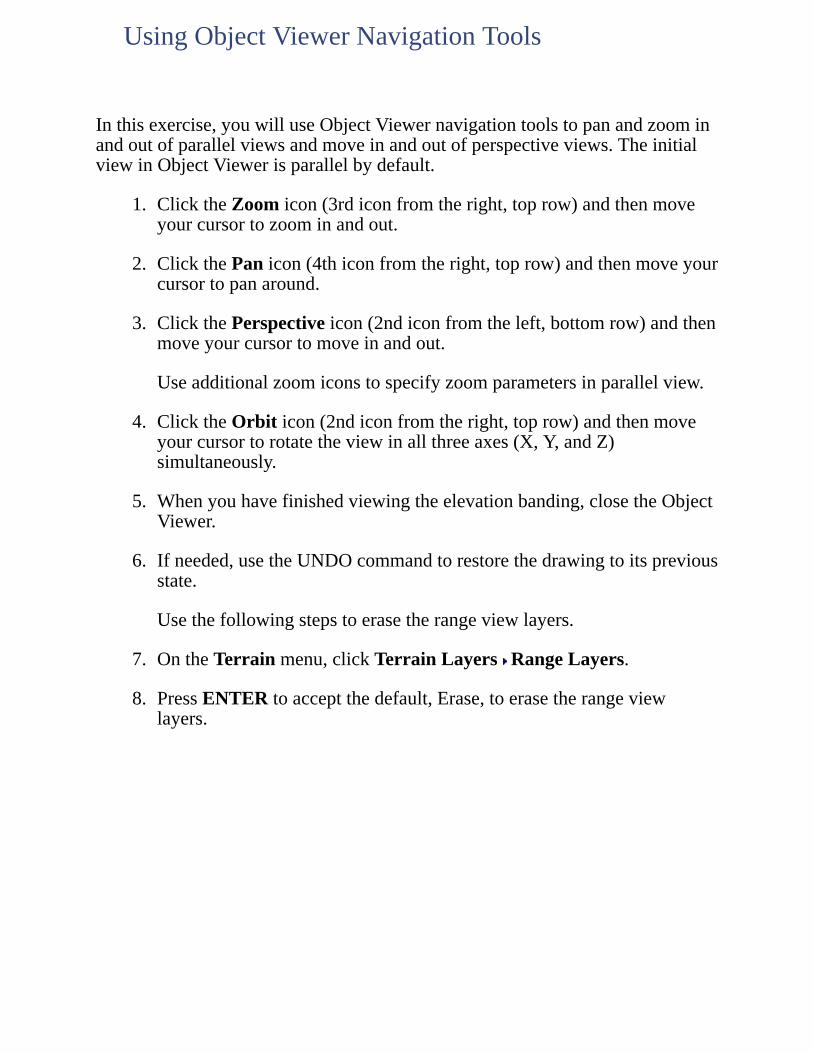
Inthisexercise,youwilluseObjectViewernavigationtoolstopanandzoominandoutofparallelviewsandmoveinandoutofperspectiveviews.TheinitialviewinObjectViewerisparallelbydefault.
1. ClicktheZoomicon(3rdiconfromtheright,toprow)andthenmoveyourcursortozoominandout.
2. ClickthePanicon(4thiconfromtheright,toprow)andthenmoveyourcursortopanaround.
3. ClickthePerspectiveicon(2ndiconfromtheleft,bottomrow)andthenmoveyourcursortomoveinandout.
Useadditionalzoomiconstospecifyzoomparametersinparallelview.
4. ClicktheOrbiticon(2ndiconfromtheright,toprow)andthenmoveyourcursortorotatetheviewinallthreeaxes(X,Y,andZ)simultaneously.
5. Whenyouhavefinishedviewingtheelevationbanding,closetheObjectViewer.
6. Ifneeded,usetheUNDOcommandtorestorethedrawingtoitspreviousstate.
Usethefollowingstepstoerasetherangeviewlayers.
7. OntheTerrainmenu,clickTerrainLayers RangeLayers.
8. PressENTERtoacceptthedefault,Erase,toerasetherangeviewlayers.
UsingObjectViewerNavigationTools
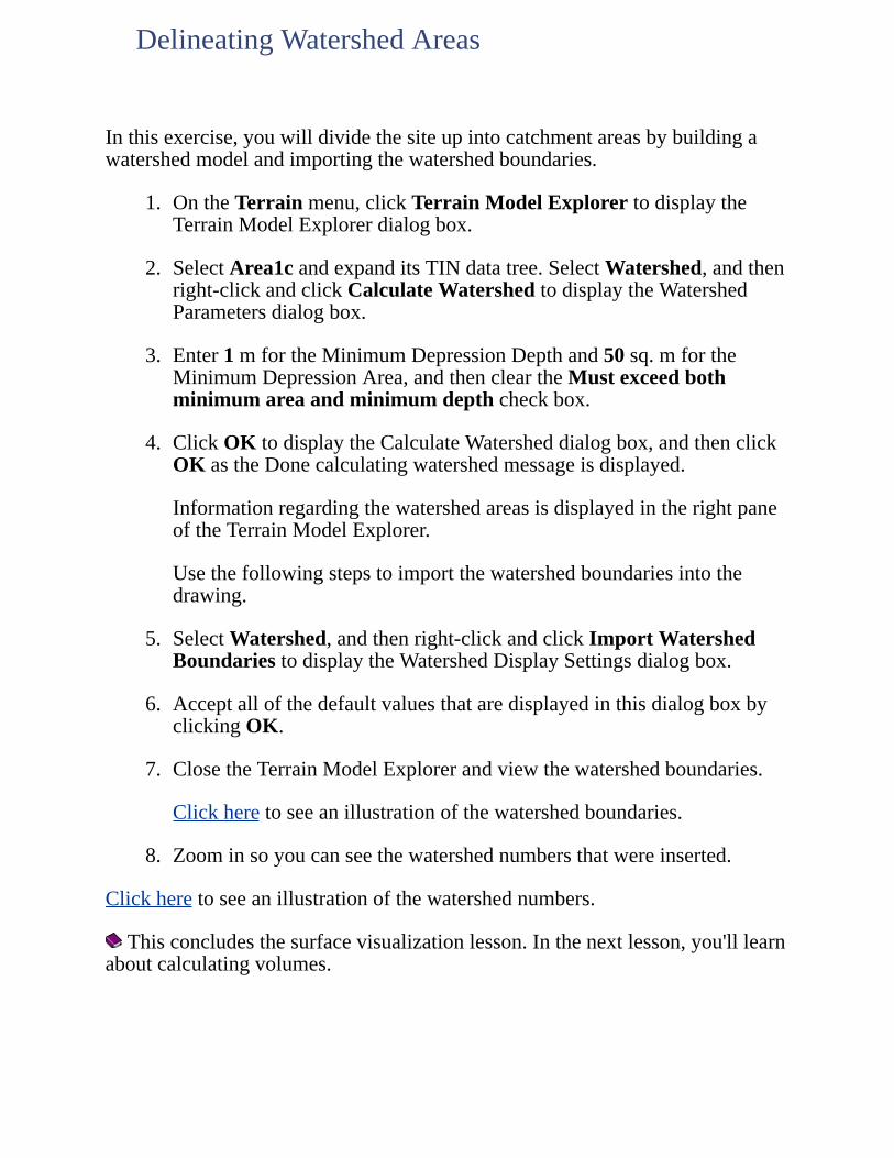
Inthisexercise,youwilldividethesiteupintocatchmentareasbybuildingawatershedmodelandimportingthewatershedboundaries.
1. OntheTerrainmenu,clickTerrainModelExplorertodisplaytheTerrainModelExplorerdialogbox.
2. SelectArea1candexpanditsTINdatatree.SelectWatershed,andthenright-clickandclickCalculateWatershedtodisplaytheWatershedParametersdialogbox.
3. Enter1mfortheMinimumDepressionDepthand50sq.mfortheMinimumDepressionArea,andthencleartheMustexceedbothminimumareaandminimumdepthcheckbox.
4. ClickOKtodisplaytheCalculateWatersheddialogbox,andthenclickOKastheDonecalculatingwatershedmessageisdisplayed.
InformationregardingthewatershedareasisdisplayedintherightpaneoftheTerrainModelExplorer.
Usethefollowingstepstoimportthewatershedboundariesintothedrawing.
5. SelectWatershed,andthenright-clickandclickImportWatershedBoundariestodisplaytheWatershedDisplaySettingsdialogbox.
6. AcceptallofthedefaultvaluesthataredisplayedinthisdialogboxbyclickingOK.
7. ClosetheTerrainModelExplorerandviewthewatershedboundaries.
Clickheretoseeanillustrationofthewatershedboundaries.
8. Zoominsoyoucanseethewatershednumbersthatwereinserted.
Clickheretoseeanillustrationofthewatershednumbers.
Thisconcludesthesurfacevisualizationlesson.Inthenextlesson,you'lllearnaboutcalculatingvolumes.
DelineatingWatershedAreas
Defineasiteandstratumforvolumecalculations,andthenperformgridandcompositesurfacevolumecalculationsandsectionmethodvolumecalculations.Comparetheresultsfromallthreemethods.
Toworkthroughthislessonfollowthesesteps
1. StartAutoCADLandDesktopifyouhavenotalreadydoneso.
2. OntheFilemenu,clickOpentodisplaytheOpenDrawing:ProjectBaseddialogbox.
Thedefaultlocationfolderforprojectfilesisc:\LandProjects<VersionNumber>.Ifyouoptedtoinstallthesefilesinanotherlocationinstead,specifytheappropriateprojectpath.
3. FromtheProjectNamelist,selectTUTORIAL1,fromtheSelectProjectDrawinglist,selectLesson-17.dwg,andthenclickOK.
4. OntheProjectsmenu,clickWorkspacestodisplaytheWorkspacestoolbar.Inthelist,selectLandDesktoptodisplaytheLandDesktopmenus.
Workingthroughtheselessonswillresultinalterationoftheprojectfiles.Backupcopiesoftheseprojectfilescanbefoundinthec:\ProgramFiles\AutoCADLandDesktop<VersionNumber>\Landtutfolder.
Ifthislessonhasbeenpreviouslyrun,copytheseunalteredprojectfilestothe\LandProjects<VersionNumber>folderwhenstartinganewtutorialsessiontoensurethatthesequenceoutlinedineachlessoncanbefollowedproperly.
LESSON17:CalculatingSiteVolumes
Inthisexercise,youwilldefineastratumfromsurfacesEGandFG,andthendefineasiteenclosingtheareainwhichvolumeswillbecalculated.
1. OntheTerrainmenu,clickSelectCurrentStratumtodisplaytheDefineStratumdialogbox.
2. EnterStratum1fortheNameandEGandFGSurfacesfortheDescription.
3. ClickSelectforSurface1todisplaytheSelectSurfacedialogbox,selectEG,andthenclickOKtoreturntotheDefineStratumdialogbox.
4. ClickSelectforSurface2todisplaytheSelectSurfacedialogbox,selectFG,andthenclickOKtoreturntotheDefineStratumdialogbox.
5. VerifythatSurface1isegandSurface2isfg,andthenclickOKtocontinue.
Usethefollowingstepstochangethevolumesitesettings.
6. OntheTerrainmenu,clickSiteDefinition SiteSettingstodisplaytheVolumeSiteSettingsdialogbox.
7. IntheVolumeLabelingsectionenterm3fortheSuffix,andthenclickOK.
Usethefollowingstepstodefinethesitewitha2mby2mgridrotated20degrees.
8. OntheTerrainmenu,clickSiteDefinition DefineSite.
9. Enter20degreesfortheRotationangle.
10. Enter.P(dotP)tousethepointfilter,andthenenter1fortheSiteBasePoint.
FiltersareavailableforyourusewhenworkingwithAutoCADLandDesktopcommands.Usethe.Ppointfiltertospecifyanexistingpointnumber,usethe.Ggraphicalfiltertoselectobjectsinthedrawing,orusethe.Nnorthingfiltertospecifynorthingandeastingcoordinates.
11. Enter2mfortheGridMsize,andthenpressENTERtoacceptthe
DefiningaStratumandaSite
default,2m,fortheGridNsize.
12. Enter.P(dotP)againtodisabletheuseofthepointfilter,andthenuseanEndpointOSNAPtoselecttheupperrightcornerofthesitedefinitionpolyline.
13. PressENTERtoacceptthedefault,No,tochangingthesizeorrotationofthegrid,andthenenterNotoerasingtheoldsiteoutline.
14. EnterSite1fortheSitename.
Withadefinedstratumandgridyouhavearelationshipbetweentwosurfacesfromwhich,byvariousmethods,youcanderivevolumes.
Inthisexercise,youwillcalculatevolumesbythegridvolumesmethod.Thegridvolumesmethodworksbysuperimposingagridonbothsurfacesinthestratum,extractingelevationsatgridlineintersections,andthencompilingthedifferenceinelevationateachconcurrentgridlineintersection.
1. OntheTerrainmenu,clickGridVolumes CalculateTotalSiteVolumetodisplaytheSiteLibrariandialogbox.
2. FromtheSelectsitelist,selectSite1,andthenclickOKtodisplaytheGridVolumeSettingsdialogbox.
3. AcceptthedefaultvaluesinthisdialogboxbyclickingOKanddisplayingtheVolumeResultsSurfacedialogbox.
4. EnterG1-Site1fortheNewsurface,andthenclickOK.
Ifyouareworkingwithseveralsitesandstrataitishelpfultodevelopanamingconventionforthevolumesurfaces.Thisaidsincorrelatingasurfacetothevolumescalculationmethodusedtocreateit.YoucanalsospecifythesitenameasthesurfacedescriptionintheTerrainModelExplorerwhencreatingsurfaces.
Thegridvolumesmethodcalculationsaredisplayedonthecommandline,withacutvolumeof3,376m3,andfillvolumeof20,380m3,andanetvolumeof17,004m3offill.
UsethefollowingstepstoturnontheboundaryofthefgsurfacethengenerateaQuickViewofthenewvolumesurface.
5. OntheViewmenu,clickNamedViewstodisplaytheViewdialogbox.UnderName,select2,clickSetCurrent,andthenclickOK.
6. ClicktheLayersiconinthetoolbartodisplaytheLayerPropertiesManager.TurnonthedisplayoftheFg-srf-bdrlayertoviewtheFGsurfaceboundarypolyline,andclickOKtoclosetheLayerPropertiesManager.
7. OntheTerrainmenu,clickSetCurrentSurfacetodisplaytheSelectSurfacedialogboxandselectVolumeSurface.SelectG1-Site1fromthelistofsurfacesandthenclickOK.
8. OntheTerrainmenu,clickSurfaceDisplay QuickView.
CalculatingGridVolumes

Clickheretoseeanillustrationofthegridvolumessurfacequickview.
Theareabetweenthefgsurfaceboundaryandtheextentofthegridvolumesurfaceisexcludedfromthevolumescalculations.
Gridsquaresthatfallpartiallyoutsideofthefinishedgroundsurfaceareignoredwhenvolumesarecalculated.Thismaybeavoidedbyusingtwosurfaceswithconcurrentboundaries,orbypastingtheproposedgroundsurfaceontotheexistinggroundsurface.Asanalternative,specifyingasmallerMandNgridsizeresultsinminimizingtheimpactofgridsquaresoccurringoutsideofthefinishedgroundsurface.

Inthisexercise,youwillcalculatevolumesbythecompositevolumesmethod.
1. OntheViewmenu,clickNamedViewstodisplaytheViewdialogbox.UnderName,select1,clickSetCurrent,andthenclickOK.
2. OntheTerrainmenu,clickCompositeVolumes CalculateTotalSiteVolumetodisplaytheSiteVolumeLibrariandialogbox.
3. FromtheSelectsitelist,selectSite1,andthenclickOKtodisplaytheCompositeVolumeSettingsdialogbox.
4. AcceptthedefaultvaluesinthisdialogboxbyclickingOKanddisplayingtheVolumeResultsSurfacedialogbox.
5. EnterC1-Site1fortheNewsurface,andthenclickOK.
Thecompositevolumesmethodcalculationsaredisplayedonthecommandline,withacutvolumeof3,475m3,andfillvolumeof20,940m3,andanetvolumeof17,465m3offill.
UsethefollowingstepstoopentheTerrainModelExplorerandviewtheC1-Site1volume.
6. OntheTerrainmenu,clickTerrainModelExplorertodisplaytheTerrainModelExplorer.
7. UndertheVolumefolderselectC1-Site1,right-clickandclickSurfaceDisplay QuickView.
8. MovetheTerrainModelExplorertoseethequickviewentities.
Clickheretoseeanillustrationofthecompositevolumessurfacequickview.
9. ClosetheTerrainModelExplorer,andthenonthecommandline,enterREDRAWtoclearthequickviewentities.
WiththeCompositeVolumesmethodnoclippingofgridsquaresoccurs,andnounexpectedsurfacetriangulationlinearegenerated,resultinginhighervolumetotalsthanwiththeGridVolumesmethod.Inthiscase,anetfillvolumeof17,465m3wasoutputusingcompositevolumes,comparedwithanetvolumeof17,004m3usinggridvolumes.
CalculatingCompositeVolumes
Inthisexercise,youwillcalculatevolumesbythesectionvolumesmethod.Withthesectionvolumesmethodtheaverageofadjacentcrosssectionareasismultipliedbythedistancebetweenthem.
First,sampleaverageendareasectionsforbothsurfaces.
1. OntheTerrainmenu,clickSectionVolumes SampleSectionstodisplaytheSiteVolumeLibrariandialogbox.
2. FromtheSelectsitelist,selectSite1,andthenclickOKtodisplaytheSectionVolumeSettingsdialogbox.
3. IntheVolumeCalculationTypesectionverifythatAverageendareaisselected,andthenintheDirectionsectionselectM(x).
4. AcceptthedefaultVolumeCorrectionsfactors,andthenclickOKtosamplesectionsforbothsurfaces.
Usethefollowingstepstocalculateaverageendareasectionvolumesforthesite.
5. OntheTerrainmenu,clickSectionVolumes CalculateVolumeTotaltodisplaytheSiteVolumeLibrariandialog.
6. FromtheSelectsitelist,selectSite1,andthenclickOKtodisplaytheSectionVolumeSettingsdialogbox.
7. AcceptthedefaultvaluesinthisdialogboxbyclickingOK,andthenpressENTER.
Thesectionvolumesmethodcalculationsaredisplayedonthecommandline,withacutvolumeof3,478m3,afillvolumeof21,012m3,andanetvolumeof17,534m3offill.
CalculatingSectionMethodVolumes

Inthisexercise,youwilllookatthevolumesresultsfromallthreevolumescalculationmethods.
1. OntheTerrainmenu,clickVolumeReports SiteReportstodisplaytheSiteVolumeCorrectionsdialogbox.
2. AcceptthedefaultvaluesinthisdialogboxbyclickingOKanddisplaytheSiteVolumeswindow.
Observethatallthreemethodsyieldvolumesthatarequiteclose,witha3.0%differencebetweenthehighestvolumesvalue(sectionaverageendareamethod),17,534m3,andthelowestvolumesvalue(gridmethod),17,004m3.
Itisrecommendedthatyouuseallthreemethodstocalculatevolumesforyourparticularsite.Soundengineeringjudgmentshouldthenbeusedtoselectthepropervalue.
3. WhenyouhavefinishedreviewingthevolumesresultsclickOK.
ViewingtheVolumeReport
Sometimesitisnecessarytocalculatevolumesforonlyaportionofthesite.Insomegeographicregionsthevolumecalculationsforasubdivisionareperformedseparatelyforlotsandroads.
UsetheParcelVolumesmethodtocalculatevolumesforaparcel.First,defineaparcelbyselectingoneoftheexistingparcelboundarypolylinesinthedrawing.
1. ClicktheLayersiconinthetoolbartodisplaytheLayerPropertiesManager.TurnonthedisplayoftheSubsiteslayertoviewtheparcelboundarypolylines,andclickOKtoclosetheLayerPropertiesManager.
2. OntheParcelsmenu,clickDefinefromPolylinesandselecttheyellowpolylinearoundthehatchedarea,andthenpressENTERtoendthecommand.
Usethefollowingstepstocalculategridvolumesforparcel1.
3. OntheTerrainmenu,clickGridVolumes CalculateParcelVolumestodisplaytheSiteVolumeLibrariandialogbox.
4. FromtheSelectsitelist,selectSite1,andthenclickOKtodisplaytheParcelVolumeLibrariandialogbox.
5. FromtheSelectparcellist,select1,andthenclickOK.
Theparcelvolumesmethodcalculationsaredisplayedonthecommandline,withacutvolumeof2,058m3,afillvolumeof3,356m3,andanetfillvolumeof1,298m3.
CalculatingParcelVolumes

Inthisexercise,youwillgeneratecutandfillcontoursforthesiteusingtheC1-Site1volumesurface.
1. ClicktheLayersiconinthetoolbartodisplaytheLayerPropertiesManager.TurnoffthedisplayoftheSubsitesandFg-srf-bdrlayers,andclickOKtoclosetheLayerPropertiesManager.
2. OntheTerrainmenu,clickSetCurrentSurfacetodisplaytheSelectSurfacedialogbox.
3. SelectVolumeSurface,fromtheSelectsurfacetoopenlist,selectC1-Site1,andthenclickOK.
4. OntheTerrainmenu,clickCreateContourstodisplaytheCreateContoursdialogbox.
5. IntheIntervalssectionselectBothMinorandMajor,enter0.5mfortheMinorIntervaland2.5mfortheMajorInterval.
6. ClickOKtocontinue,andthenpressENTERtoacceptthedefault,Yes,forerasingoldcontours.
Thecutandfillcontoursaredrawntorepresentthedepthofequalcutandfillacrossthesite.
Clickheretoseeanillustrationofthecutandfillcontours.
GeneratingCutandFillContours

Inthisexercise,youwillgenerategridticksandlabelstoshowcutandfillvolumevaluesatspecifiedgridpoints.
1. OntheTerrainmenu,clickGridVolumes GridVolumeTickstodisplaytheSiteVolumeLibrariandialogbox.
2. FromtheSelectsitelist,selectSite1,andthenclickOKtodisplaytheGridVolumeTicksdialogbox.
3. Enter5fortheTickintervalandLabelinterval,andthenenter1fortheLabelprecision.
4. IntheLabelPositionsectionselectRight,andthenclickOK.
5. EnterNotonoteraseoldticks.
Thegridticksandlabelsaregenerated.
6. Zoominononeofthegridticksandlabels.
Clickheretoseeanillustrationofgridticksandlabels.
Thisconcludesthevolumecalculationlesson.Inthenextlesson,you'lllearnaboutdrawinglines,curves,andspirals.
GeneratingGridTicksandLabels
Drawtangents,curves,andspiralstolayoutalignmentcenterlines.Createnewalignmentsandeditexistingalignmentsbyconnectingtangentsegmentswithcircularcurvesandspirals.Usespeedtablestodrawcurvesandworkwithattachingmultiplealignmentobjects.
Toworkthroughthislessonfollowthesesteps:
1. StartAutoCADLandDesktopifyouhavenotalreadydoneso.
2. OntheFilemenu,clickOpentodisplaytheOpenDrawing:ProjectBaseddialogbox.
Thedefaultlocationfolderforprojectfilesisc:\LandProjects<VersionNumber>.Ifyouoptedtoinstallthesefilesinanotherlocationinstead,specifytheappropriateprojectpath.
3. FromtheProjectNamelist,selectTUTORIAL2,fromtheSelectProjectDrawinglist,selectLesson-18.dwg,andthenclickOK.
4. OntheProjectsmenu,clickWorkspacestodisplaytheWorkspacestoolbar.Inthelist,selectLandDesktoptodisplaytheLandDesktopmenus.
Workingthroughtheselessonswillresultinalterationoftheprojectfiles.Backupcopiesoftheseprojectfilescanbefoundinthec:\ProgramFiles\AutoCADLandDesktop<VersionNumber>\Landtutfolder.
Ifthislessonhasbeenpreviouslyrun,copytheseunalteredprojectfilestothe\LandProjects<VersionNumber>folderwhenstartinganewtutorialsessiontoensurethatthesequenceoutlinedineachlessoncanbefollowedproperly.
LESSON18:DrawingTangents,Curves,andSpirals
Inthisexercise,youwilldrawtangentsegmentsbetweentwoexistingPIs,apointspecifiedbynorthing/eastingcoordinates,andastationblocktodefineabridgeabutmentalignmentcrossingthemainroadwayalignment.
1. OntheViewmenu,clickNamedViewstodisplaytheViewdialogbox.UnderName,select2,clickSetCurrent,andthenclickOK.
2. OntheLines/Curvesmenu,clickLine,enter.P(dotP)tousethePointfilter,andthenenter1forthePointnumberofthestartingpoint.
3. Enter2forthePointnumberofthenextpoint.
4. Enter.N(dotN)tousetheNorthing/Eastingfilter,andthenenter5018657.3345fortheNorthingvalueand273727.9099fortheEastingvalueforthenextpoint.
5. Enter.NtotoggleofftheNorthing/Eastingfilter,andthenuseanInsertionOsnaptoselectthestationblockonthenorthsideofthemainroadfortheendingpoint.
6. PressENTERtwice.
Younowhavethreetangentsegmentsforthebridgeabutmentalignment.
Clickheretoseeanillustrationofthebridgeabutmenttangents.
DrawingTangents

Inthisexercise,youwilldraw700mradiuscircularcurvesbetweeneachofthethreetangentsegmentsthatyoujustdrew.
1. OntheLines/Curvesmenu,clickCurveBetweenTwoLines,selectthefirsttangentline,andthenselectthesecondtangentline.
2. PressENTERtoacceptthedefault,Radius,andthenenter700mfortheRadius.
3. Selectthesecondtangentline,andthenselectthethirdtangentline.
4. PressENTERtoacceptthedefault,Radius,enter700mfortheRadius,andthenpressENTER.
Thethreetangentsegmentsareconnectedwithcircularcurvestocompletethebridgeabutmentalignment.
Clickheretoseeanillustrationofthebridgeabutmentalignmentcurves.
DrawingCurves
Inthisexercise,youwilldrawaspiral-curve-spiralsystemtoconnecttangentsegmentsonthemainroadwayalignment.First,verifythatyouwilluseaclothoidspiral.
1. OntheViewmenu,clickNamedViewstodisplaytheViewdialogbox.UnderName,select3,clickSetCurrent,andthenclickOK.
2. OntheLines/Curvesmenu,clickCreateSpirals SpiralTypetodisplaytheSpiralTypedialogbox.
3. VerifythatClothoidisselected,andthenclickOK.
4. OntheLines/Curvesmenu,clickCreateSpirals FitTangent-TangenttodisplaytheFitSpirals-TangenttoTangentdialogbox.
5. FromtheDescriptionlist,selectSpiral-Curve-Spiral,andthenclickOK.
6. Selectthelefttangent,andthenselecttherighttangent.
7. Enter850mfortheRadius,andthenenter300fortheSpiralAinvalue.
8. PressENTERtoacceptthedefault,300,fortheSpiralAoutvalue,andthenpressENTER.
Thetangentsareconnectedwithspiralsandan850mradiuscurve.
Clickheretoseeanillustrationofthemainalignmentspiral-curve-spiralsystem.
DrawingSpirals
Inthisexercise,youwillusespeedtablestodrawacurvesystemforanotherpartofthemainroadwayalignment.Thedesignintentistosuperelevatethisroadwaycurve.CopytheCanada06speedtabletocreateanewspeedtablebasedonadesignspeedof110km/hrand1000mradiuscurve.
1. OntheViewmenu,clickNamedViewstodisplaytheViewdialogbox.UnderName,select4,clickSetCurrent,andthenclickOK.
2. OntheLines/Curvesmenu,clickSpeedTables EditSpeedTabletodisplaytheSelectSpeedTabledialogbox.
3. FromtheSpeedTablelist,selectcanada06.sup,andthenclickOKtodisplaytheHorizontalSpeedTabledialogbox.
4. FromtheDesignSpeedlist,select110km/hr.
5. ClickSaveAstodisplaytheSaveHorizontalSpeedTabledialogbox.
6. EnterTutorialfortheFilename,andthenclickSavetoreturntotheHorizontalSpeedTabledialogbox.
7. ClickintheeighthrowoftheSpeedTable(1000mradiuscurve),andthenclickEdittodisplaytheNew/EditSpeedTableItemdialogbox.
8. Enter350forthe4LaneSpiAvalue,andthenclickOKtoreturntotheHorizontalSpeedTabledialogbox.
9. ClickSave,andthenclickOK.
Usethefollowingstepstodrawanew4-lanecurvesystembasedontheTutorialspeedtableforthemainroadwayalignment.
10. OntheLines/Curvesmenu,clickSpeedTables CreateCurves.
11. Selectthelefttangent,andthenselecttherighttangenttodisplaytheHorizontalSpeedTabledialogbox.
12. VerifythatTutorial.supisthecurrentSpeedtableand110km/hristheDesignspeed.
13. ClickintheeighthrowoftheSpeedTablecolumn(1000mradius),andthenclickOKtodisplaytheSelectdialogbox.
WorkingwithSpeedTables

14. ClickFourLanestocreatethespiral-curve-spiralsystem.
Thetangentsareconnectedwithacurvesystemgeneratedbythenewspeedtable.
Clickheretoseeanillustrationofthespeedtablecurvesystem.

Inthisexercise,youwillcreateanexitrampalignmentbyattachingmultiplealignmentobjects.First,offsettheroadwaycenterlinetangent26msouthasthestartoftheramp.
1. OntheViewmenu,clickNamedViewstodisplaytheViewdialogbox,underName,select5,clickSetCurrent,andthenclickOK.
2. Onthecommandline,enterOFFSET,enter26mfortheDistance,andthenselectthelefttangentontheleftsideofyourscreen.
3. SelectapointbelowthetangentfortheSidetooffset,andthenpressENTER.
Usethefollowingstepstoadda1280mradiuscurvetotherightendoftheramp.
4. OntheLines/Curvesmenu,clickAttachMultiple.
5. Selecttherightendofthenewoffsetramptangent.
6. EnterAfortheArcoption,andthenpressENTERtoacceptthedefault,Radius.
7. Enter1280mfortheRadius,pressENTERtoacceptthedefault,Length,andthenenter206.8mfortheLength.
Usethefollowingstepstoattachacompoundspiraltothecurve.
8. EnterSfortheSpiraloption,andthenenterCfortheCompoundoption.
9. PressENTERtoacceptthedefault,1280m,fortheRadius.
10. EnterLfortheLengthoption,andthenenter54.397mfortheLength.
11. Enter250mfortheEndingradius.
Usethefollowingstepstoattachanothercurvetothecompoundspiral.
12. EnterAfortheArcoption,pressENTERtoacceptthedefault,Radius,andthenpressENTERtoacceptthedefault,250m,fortheRadius.
13. PressENTERtoacceptthedefault,Length,andthenenter106.304m
AttachingMultipleAlignmentObjects

fortheLength.
Usethefollowingstepstoattachaspiraltothecurve.
14. EnterSfortheSpiraloption,andthenenterOfortheOutcurveoption.
15. PressENTERtoacceptthedefault,250m,fortheRadius,enterAfortheAfactoroption,andthenenter146.615fortheAfactor.
Usethefollowingstepstofinishtherampalignmentbydrawingatangentsegment.
16. EnterTfortheTangentoption,andthenenter206.016mfortheLength.
17. PressENTERtoendthecommand.
Therampalignmentisrepresentedbymultiplealignmentobjects.
Clickheretoseeanillustrationoftherampalignment.
Takealookatallofthealignmentobjectsinthedrawing.
18. OntheViewmenu,clickNamedViewstodisplaytheViewdialogbox,underName,select1,clickSetCurrent,andthenclickOK.
Thisconcludestheobjectdrawinglesson.Inthenextlesson,you'lllearnaboutdefiningandeditingalignments.
Definealignmentsforroadwaycenterlines,curblines,orotherroadwayfeaturesfrompolylinesorindividualentities.EditalignmentsandgeneratealignmentreportswiththeHorizontalAlignmentEditor.
Toworkthroughthislessonfollowthesesteps
1. StartAutoCADLandDesktopifyouhavenotalreadydoneso.
2. OntheFilemenu,clickOpentodisplaytheOpenDrawing:ProjectBaseddialogbox.
Thedefaultlocationfolderforprojectfilesisc:\LandProjects<VersionNumber>.Ifyouoptedtoinstallthesefilesinanotherlocationinstead,specifytheappropriateprojectpath.
3. FromtheProjectNamelist,selectTUTORIAL2,fromtheSelectProjectDrawinglist,selectLesson-19.dwg,andthenclickOK.
4. OntheProjectsmenu,clickWorkspacestodisplaytheWorkspacestoolbar.Inthelist,selectLandDesktoptodisplaytheLandDesktopmenus.
Workingthroughtheselessonswillresultinalterationoftheprojectfiles.Backupcopiesoftheseprojectfilescanbefoundinthec:\ProgramFiles\AutoCADLandDesktop<VersionNumber>\Landtutfolder.
Ifthislessonhasbeenpreviouslyrun,copytheseunalteredprojectfilestothe\LandProjects<VersionNumber>folderwhenstartinganewtutorialsessiontoensurethatthesequenceoutlinedineachlessoncanbefollowedproperly.
LESSON19:DefiningandEditingAlignments
Inthisexercise,youwilldefinethefirstalignmentfromtheredalignmentpolyline.
1. OntheAlignmentsmenu,clickDefinefromPolyline.
2. Selectapointonthepolyline.
AredXappearsatthestartingpointofthepolyline.
3. PressENTERtoacceptthestartingpointasthealignmentreferencepointandtodisplaytheDefineAlignmentdialogbox.
4. EnterA1fortheAlignmentnameandAlignment#1-SeguinTrailfortheDescription.
5. AccepttheStartingstationof0.000,andthenclickOKtocontinue.
Thefirstalignmentisdefinedfromapolyline.Dataforthenewalignmentisdisplayedonthecommandlineincludingthealignmentdescription,name,number,length,andstartingandendingstations.
ClickheretoseeanillustrationoftheA1alignment.
Ifthealignmentcontainsspiralsitmustbedefinedfromentities,ratherthandefinedfromapolyline.
DefininganAlignmentfromaPolyline
Inthisexercise,youwilldefinethesecondalignmentfromindividualobjects.
1. OntheViewmenu,clickNamedViewstodisplaytheViewdialogbox.UnderName,select2,clickSetCurrent,andthenclickOK.
2. FromtheLayerlist,turnontheCL-2layer.
TheyellowalignmentontheCL-2layernowappearsinthedrawing.Thisalignmentiscomprisedofconnectedalignmentobjects.Defineasecondalignmentfromtheseobjects,startingwiththerightendofthealignment.
3. OntheAlignmentsmenu,clickDefinefromObjects.
4. Selecttherightendofthefirsttangentontherightendofthealignment.
AredXappearsatthestartingpointofthealignment.
5. Useawindowselectionsettoselecttherestoftheentitiesinthealignment,andthenpressENTER.
Usethefollowingstepstospecifyareferencepointatthecenterofanexistingcirclepositionedonthealignment,andthenspecifyareferencestationvalue.
6. AttheSelectReferencePointpromptonthecommandline,enter'-VIEW(apostrophedashVIEW),RfortheRestoreoption,andthen3fortheviewtorestore.
7. UseaCenterOsnaptoselectthecenterofthecircleasthereferencepoint,andthenenter15778.63fortheReferencestationvalue.
8. PressENTERtodisplaytheDefineAlignmentdialogbox.
9. EnterA2fortheAlignmentnameandAlignment#2-Highway69fortheDescription.
10. AccepttheStartingstationvalueof15299.008,andthenclickOKtocontinue.
11. OntheViewmenu,clickNamedViewstodisplaytheViewdialogbox.UnderName,select2,clickSetCurrent,andthenclickOK.
DefininganAlignmentfromObjects

Thesecondalignmentisdefinedfromobjects.
ClickheretoseeanillustrationoftheA2alignment.
Inthisexercise,youwillusetheHorizontalAlignmentEditortoviewandeditPI,curve,andspiraldataforalignmentA2.
1. OntheAlignmentsmenu,clickEdittodisplaytheHorizontalAlignmentEditor.
Usethefollowingstepstoviewdataforthefirstcurveinthealignment.
2. IntheEditsection,clickinthesecondrowoftheStationcolumn,andthenclickEditCurvetodisplaytheCurveDetailWindow.
3. Whenyouhavefinishedreviewingthedataforthefirstcurve,clickNexttoviewdataforthesecondcurve.
4. Whenyouhavefinishedreviewingthedataforthesecondcurve,clickOKtoreturntotheHorizontalAlignmentEditor.
UsethefollowingsteptochangetheNorthingvalueforthefourthPIpointofthealignmenttomoveitsouth40m.
5. ClickinthefourthrowoftheNorthingcolumn,enter5018525.433asthenewNorthingvalue,andthenpressENTER.
Thestationanddirectionvalueschangefortheadjacenttangentsegmentinthealignment.
ViewingandEditingAlignmentData

Inthisexercise,youwillgenerateanalignmentreportfile.
1. IntheHorizontalAlignmentEditor,intheReportssection,clickSettingstodisplaytheOutputSettingsdialogbox.
2. IntheOutputOptionssection,selecttheFilecheckbox.
Specifyanameandlocationforthealignmentreportfile.
3. ClickOutputFileNametodisplaytheOutputFileNamedialogbox,specifyalocationforthealignmentreportfile,andthenenterReport1.prnfortheOutputfilename.
4. ClickSavetoreturntotheOutputSettingsdialogbox,andthenclickOKtoreturntotheHorizontalAlignmenteditor.
5. ClickStation/Curve,pressENTERtoacceptthedefaultbeginningstation,andthenpressENTERtoacceptthedefaultendingstation.
6. PressENTERtoacceptthedefaultOutputfilename,Report1.prn,anddisplaytheHorizontalAlignmentStationandCurveReportdialogbox.
7. Whenyouhavefinishedreviewingthedatainthisdialogbox,clickOKtoreturntotheHorizontalAlignmentEditordialogbox.
8. ClickSave,andthenclickOK.
ThealignmenthasmovedinthedrawingtoreflectthechangesmadeintheHorizontalAlignmentEditor.
Thisconcludesthealignmentcreationandeditinglesson.Inthenextlesson,you'lllearnaboutstationingandoffsettingalignments.
GeneratingAlignmentReports
Stationalignmentstodefineevenincrementsofalignmentmeasurement.Createoffsetstoquicklygenerateroadwaydetailssuchasedgeofpavement,edgeofshoulder,andsoon.
Toworkthroughthislessonfollowthesesteps
1. StartAutoCADLandDesktopifyouhavenotalreadydoneso.
2. OntheFilemenu,clickOpentodisplaytheOpenDrawing:ProjectBaseddialogbox.
Thedefaultlocationfolderforprojectfilesisc:\LandProjects<VersionNumber>.Ifyouoptedtoinstallthesefilesinanotherlocationinstead,specifytheappropriateprojectpath.
3. FromtheProjectNamelist,selectTUTORIAL2,fromtheSelectProjectDrawinglist,selectLesson-20.dwg,andthenclickOK.
4. OntheProjectsmenu,clickWorkspacestodisplaytheWorkspacestoolbar.Inthelist,selectLandDesktoptodisplaytheLandDesktopmenus.
Workingthroughtheselessonswillresultinalterationoftheprojectfiles.Backupcopiesoftheseprojectfilescanbefoundinthec:\ProgramFiles\AutoCADLandDesktop<VersionNumber>\Landtutfolder.
Ifthislessonhasbeenpreviouslyrun,copytheseunalteredprojectfilestothe\LandProjects<VersionNumber>folderwhenstartinganewtutorialsessiontoensurethatthesequenceoutlinedineachlessoncanbefollowedproperly.
LESSON20:CreatingAlignmentStationingandOffsets
Inthisexercise,youwillchangestationsettingsbyspecifyingthestationbasevalue,addingalayerprefix,andbeginningofcurveandcurve/tangentintersectlabels.
1. OntheAlignmentsmenu,clickStationDisplayFormattodisplaytheEditStationFormatdialogbox.
2. IntheStation/ChainageNumericFormatsectionchangetheStationbasevalueto1000bymovingtheslidertotheright,andthenclickOK.
3. OntheAlignmentsmenu,clickAlignmentLabelstodisplaytheAlignmentLabelsSettingsdialogbox.
4. IntheLayerPrefixsection,enter*-(asteriskhyphen)fortheLayerprefix.
Thiswillappendthealignmentnameautomaticallytoallofthelayersthatareautomaticallycreatedwhengeneratingalignmentstationing.
5. IntheLabelTextsection,enterBCfortheBeginningofcurveandECfortheCurve/Tangentintersect,andthenclickOK.
Althoughstationingcanbeaccomplishedinasingleoperation,thislessonshowsyouhowtocreatestationlabelswithaspecifictextstyleandoffsetfirst,andthenstationpointlabelswithadifferenttextstyleandoffset.
6. OntheAlignmentsmenu,clickStationLabelSettingstodisplaytheAlignmentStationLabelSettingsdialogbox.
7. CleartheStationpointlabelscheckbox,enter50mfortheStationlabelincrement,10mfortheStationtickincrement,and2mfortheStationlabeloffset,andthenclickOK.
8. OntheUtilitiesmenu,clickSetTextStyletodisplaytheTextStyledialogbox.
9. FromtheStyleNamelist,select2MM,andthenclickClose.
Younowhaveanewstationlabelstyle.
ChangingStationSettings
Inthisexercise,youwilladdstationlabelstothealignment.First,setalignmentA1basthecurrentalignment.
1. OntheAlignmentsmenu,clickSetCurrentAlignment,andthenpressENTERtodisplaytheAlignmentLibrariandialogbox.
2. FromtheSelectionlist,selectA1b,andthenclickOK.
3. OntheAlignmentsmenu,clickCreateStationLabels.
4. Acceptthedefaultbeginningandendingstationvalues,andthenpressENTERtoacceptthedefault,Yes,todeleteexistingstationinglayers.
Thestationlabelsareautomaticallygenerated.
Clickheretoseeanillustrationofthestationlabels.
Usethefollowingstepstoaddstationpointlabelstothealignment.
5. OntheAlignmentsmenu,clickStationLabelSettingstodisplaytheAlignmentStationingSettingsdialogbox.
6. CleartheStationlabelscheckbox,selecttheStationpointlabelscheckbox,enter25mfortheStationlabeloffset,andthenclickOK.
7. OntheUtilitiesmenu,clickSetTextStyletodisplaytheTextStyledialogbox.
8. FromtheStyleNamelist,select3MM,andthenclickClose.
Younowhaveanewstationpointlabelstyle.
9. OntheAlignmentsmenu,clickCreateStationLabels.
10. Acceptthedefaultbeginningandendingstationvalues,andthenpressENTERtoacceptthedefault,Yes,todeleteexistingstationinglayers.
Thestationpointlabelsareautomaticallygenerated.Whenyouareworkingwithsomesmaller-radiuscurvesthestationpointlabelsmayneedtobemanuallyadjustedforclarity.
11. Zoominonthealignmenttoviewthestationpointlabels.
GeneratingAlignmentStationing

Clickheretoseeanillustrationofthestationpointlabels.
Inthisexercise,youwilladdedgeofpavement,shoulder,andright-of-wayoffsetstothealignment.
1. Zoomtothepreviousview.
2. OntheAlignmentsmenu,clickCreateOffsetstodisplaytheAlignmentOffsetSettingsdialogbox.
3. IntheOuteroffsetsection,enter0(zero)mfortheLeftoffsetand25mfortheRightoffset.
4. IntheSecondoffsetsection,selecttheSecondoffsetcheckbox,andthenenter6.5mforboththeLeftandRightoffsets.
5. IntheInneroffsetsection,verifythattheLeftandRightoffsetvalueis4.25m,andthenclickOK.
Thealignmentoffsetsareautomaticallygenerated.
Clickheretoseeanillustrationofthealignmentoffsets.
WhenworkingwiththeAlignmentOffsetSettingsdialogbox,youdonothavetheoptionofautomaticallyerasingalignmentoffsetobjects.ToavoidgeneratingduplicatealignmentoffsetobjectsclickCanceltoexittheAlignmentOffsetSettingsdialogboxwhenyouareonlycheckingsettings.
ThisconcludestheAutoCADLandDesktoptutorial.
FormoreinformationaboutthefeaturesofAutoCADLandDesktop,seetheonlinehelp.
CreatingOffsets

NOTETheCivilEngineeringTutorialsdescribedinthischapterareavailablewhenyouinstallAutoCAD®Civil3D®LandDesktopCompanion2008.Thestand-aloneinstallationofAutoCADLandDesktopdoesnotincludethesefeatures.
WelcometotheCivilEngineeringToolstutorial.
Thistutorialhas16lessonsaboutprofiles,crosssections,templates,superelevation,transitioning,andgrading.
Youcanworkthroughtheselessonssequentially,oryoucandoonelessonatatime.Everylessonhasatutorialdrawingandanaccompanyingdataset.
ClickLesson21intheContentstabtomovetothenexttask..
CivilEngineeringTutorials

NOTETheCivilEngineeringTutorialsdescribedinthischapterareavailablewhenyouinstallAutoCAD®Civil3D®LandDesktopCompanion2008.Thestand-aloneinstallationofAutoCADLandDesktopdoesnotincludethesefeatures.
WelcometotheCivilEngineeringToolstutorial.
Thistutorialhas16lessonsaboutprofiles,crosssections,templates,superelevation,transitioning,andgrading.
canworkthroughtheselessonssequentially,oryoucandoonelessonataEverylessonhasatutorialdrawingandanaccompanyingdataset.
Lesson21intheContentstabtomovetothenexttask..
CivilEngineeringTutorials

NOTETheSurveyingTutorialsdescribedinthischapterareavailablewhenyouinstallAutoCAD®Civil3D®LandDesktopCompanion2008.Thestand-aloneinstallationofAutoCADLandDesktopdoesnotincludethesefeatures.
Welcometothesurveyingtoolstutorial.
Thistutorialhastwolessonsaboutworkingwithsurveydata:
Lesson37:UsingSurveyToolspace.Thislessonprovidesexercisesonadding,editing,andviewingsurveydatausingtheSurveyToolspace,whichisacentralizedinterfaceformanagingandeditingsurveycontrolpointdata,surveysetupdata,surveyobservationdata,andsurveyfiguredata.
Lesson38:UsingOtherSurveyFeatures:ThislessonprovidesexercisesonotherSurveyfeaturesaswellasalternativewaysofinputting,adjusting,andviewingsurveydata.
Thesurveyingtoolscontainacompletesetoftoolsforthesurveyortodownloadandprocesssurveyinformation,performadjustmentsonnetworkandtraversedata,andimportthosesurveypointsintoanAutoCADdrawing.
Thesurveyingtoolsalsoprovideadditionaloptionsfordetailingpointswithfiguresandlinework.OtheroptionsprovidethecapabilityofcalculatingdirectionsbasedonSunandStarshotinformation.Formoreinformation,seetheSurveyingToolsonlineHelp.
NoteBeforeusingthistutorial,youshouldbefamiliarwithAutoCADLandDesktop.Ifyouhaven'thadexperienceusingtheAutoCADLandDesktop,reviewtheAutoCADLandDesktopTutorial.
ClickLesson37intheContentstabtomovetothenexttask.
SurveyingTutorials

NOTETheSurveyingTutorialsdescribedinthischapterareavailablewhenyouinstallAutoCAD®Civil3D®LandDesktopCompanion2008.Thestand-aloneinstallationofAutoCADLandDesktopdoesnotincludethesefeatures.
Welcometothesurveyingtoolstutorial.
Thistutorialhastwolessonsaboutworkingwithsurveydata:
Lesson37:UsingSurveyToolspace.Thislessonprovidesexercisesonadding,editing,andviewingsurveydatausingtheSurveyToolspace,whichisacentralizedinterfaceformanagingandeditingsurveycontrolpointdata,surveysetupdata,surveyobservationdata,andsurveyfiguredata.
Lesson38:UsingOtherSurveyFeatures:ThislessonprovidesexercisesonotherSurveyfeaturesaswellasalternativewaysofinputting,adjusting,andviewingsurveydata.
Thesurveyingtoolscontainacompletesetoftoolsforthesurveyortodownloadandprocesssurveyinformation,performadjustmentsonnetworkandtraversedata,andimportthosesurveypointsintoanAutoCADdrawing.
Thesurveyingtoolsalsoprovideadditionaloptionsfordetailingpointswithfiguresandlinework.OtheroptionsprovidethecapabilityofcalculatingdirectionsbasedonSunandStarshotinformation.Formoreinformation,seetheSurveyingToolsonlineHelp.
Beforeusingthistutorial,youshouldbefamiliarwithAutoCADLandDesktop.Ifyouhaven'thadexperienceusingtheAutoCADLandDesktop,reviewtheAutoCADLandDesktopTutorial.
Lesson37intheContentstabtomovetothenexttask.
SurveyingTutorials
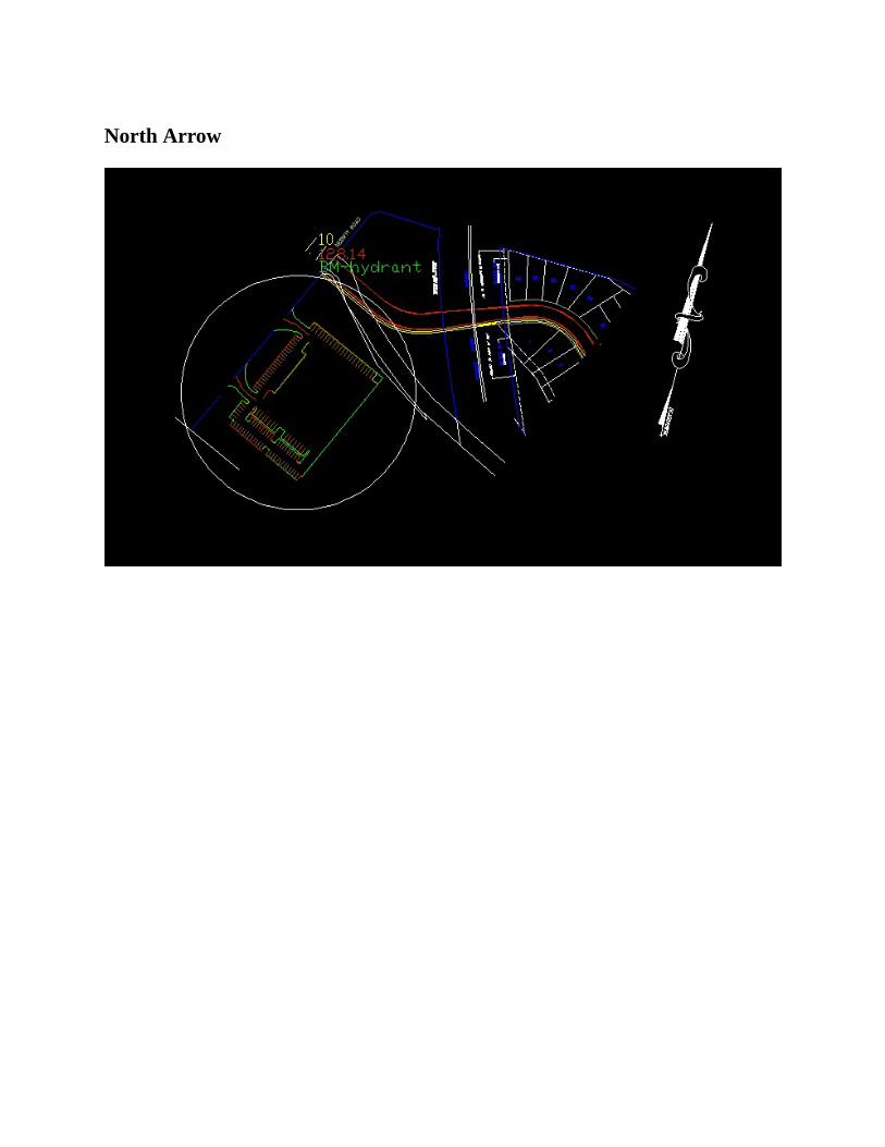
NorthArrow
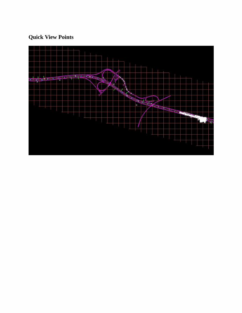
QuickViewPoints
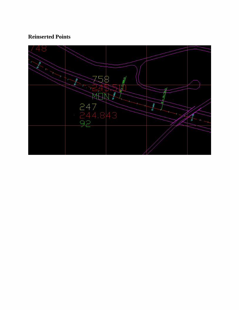
ReinsertedPoints
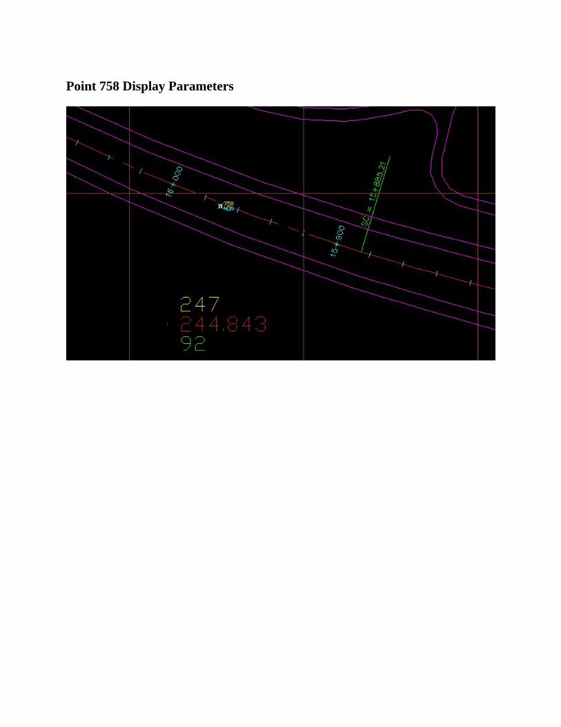
Point758DisplayParameters
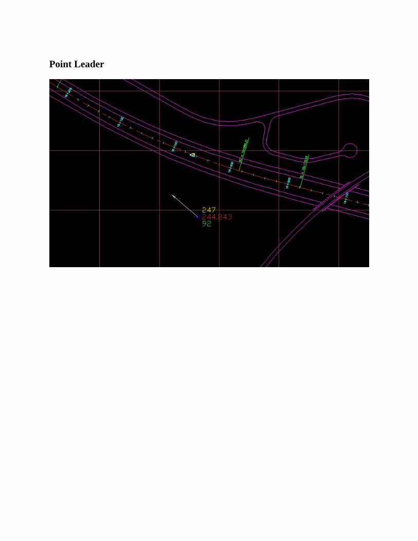
PointLeader
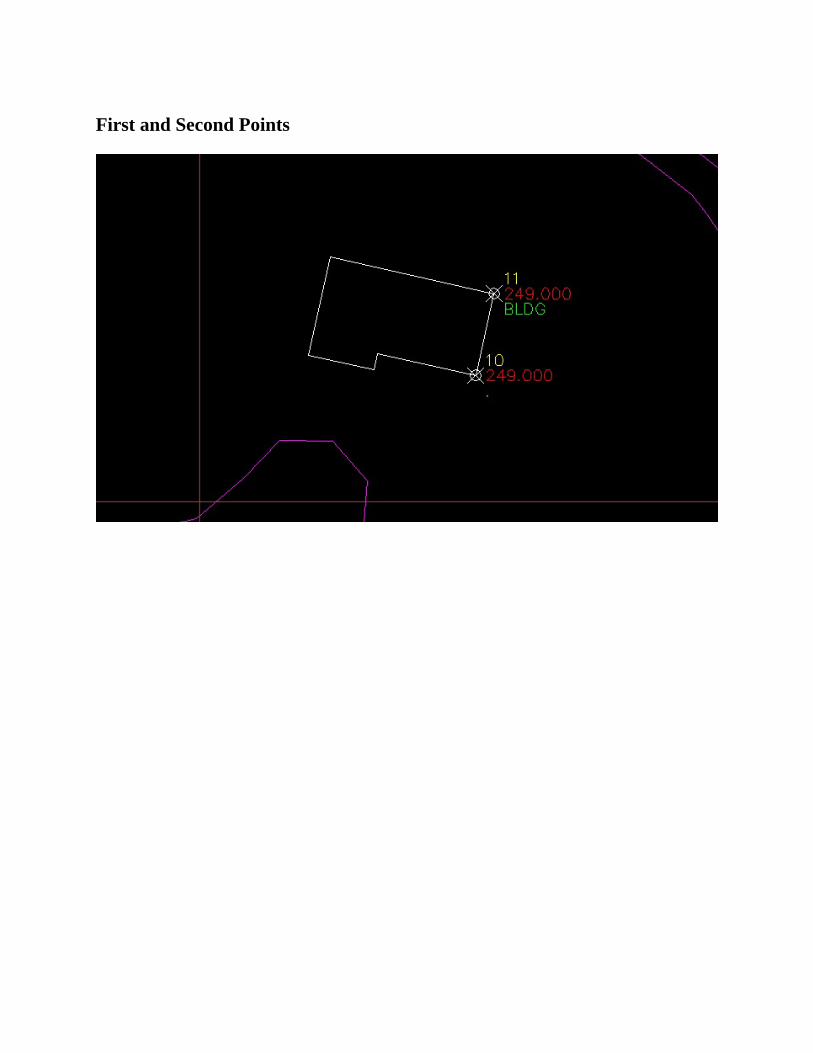
FirstandSecondPoints
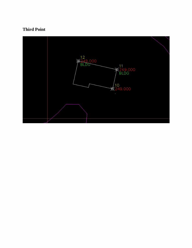
ThirdPoint
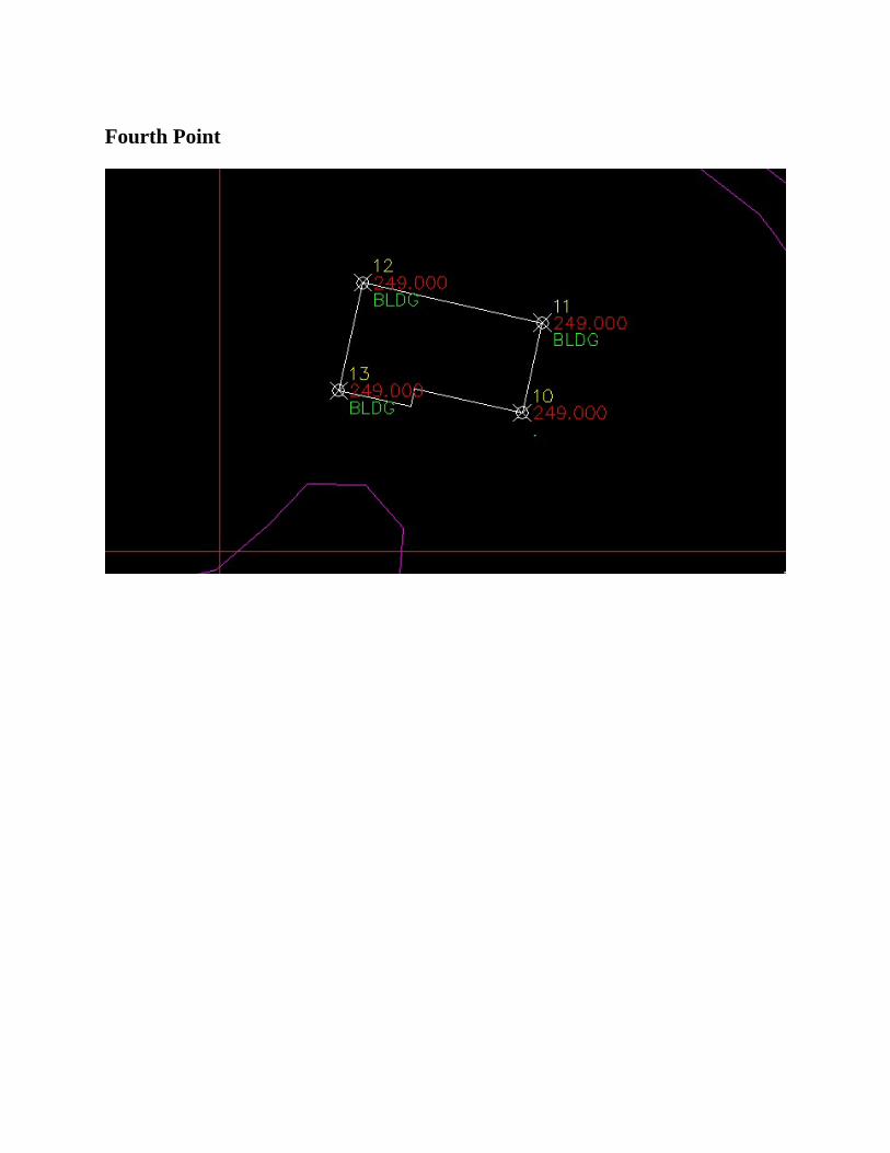
FourthPoint
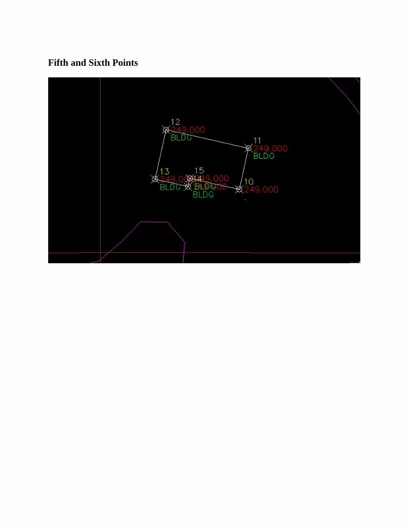
FifthandSixthPoints
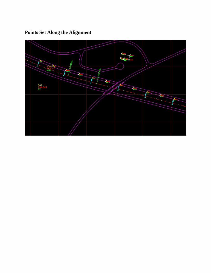
PointsSetAlongtheAlignment
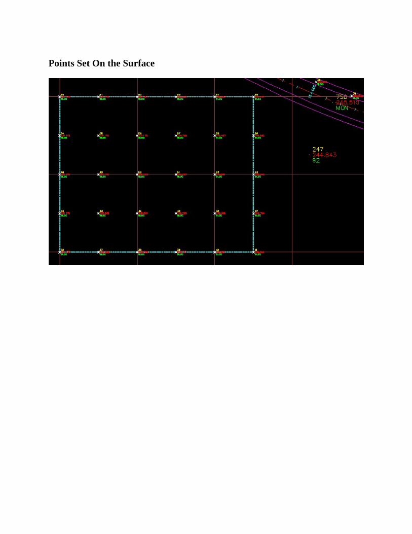
PointsSetOntheSurface
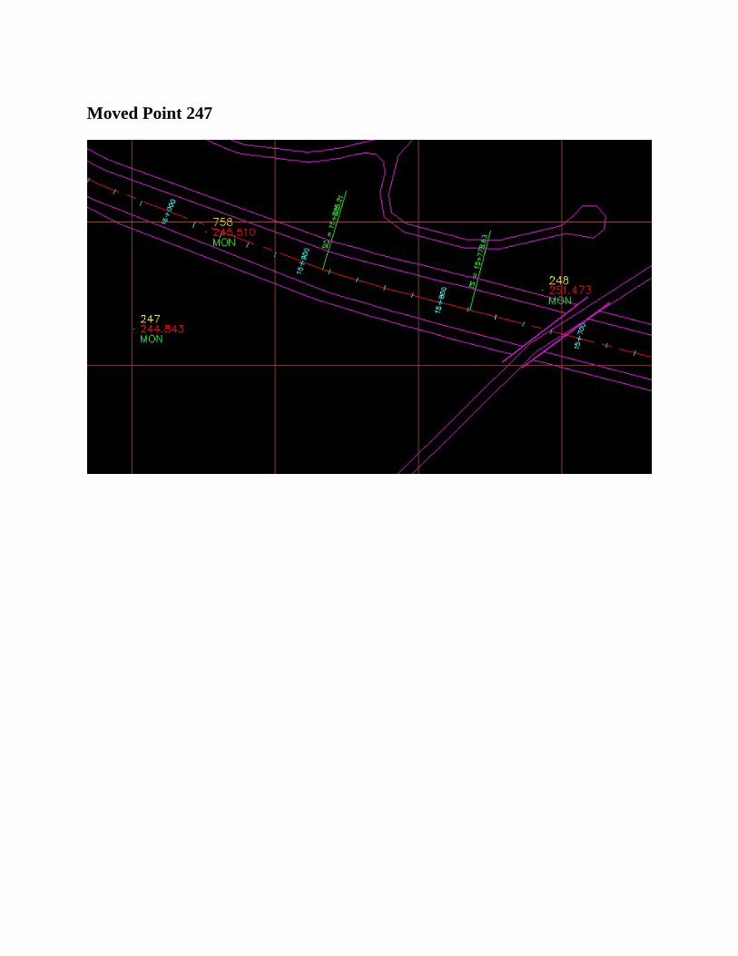
MovedPoint247
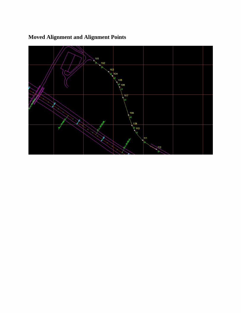
MovedAlignmentandAlignmentPoints
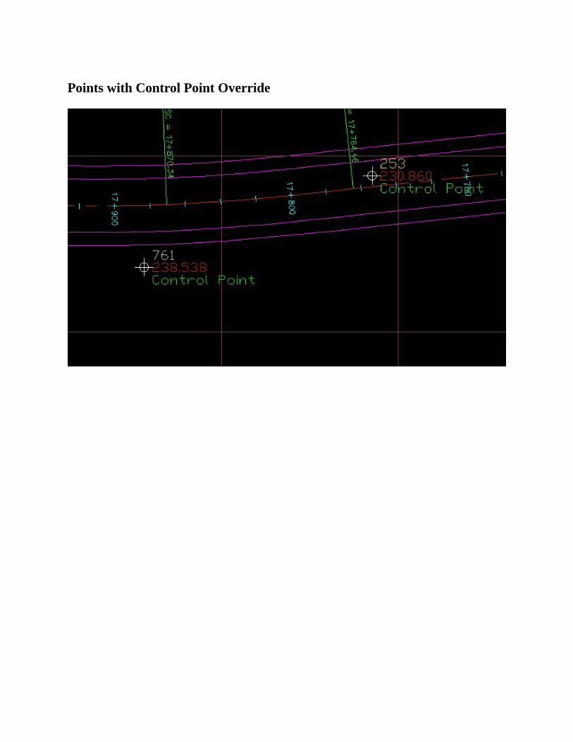
PointswithControlPointOverride
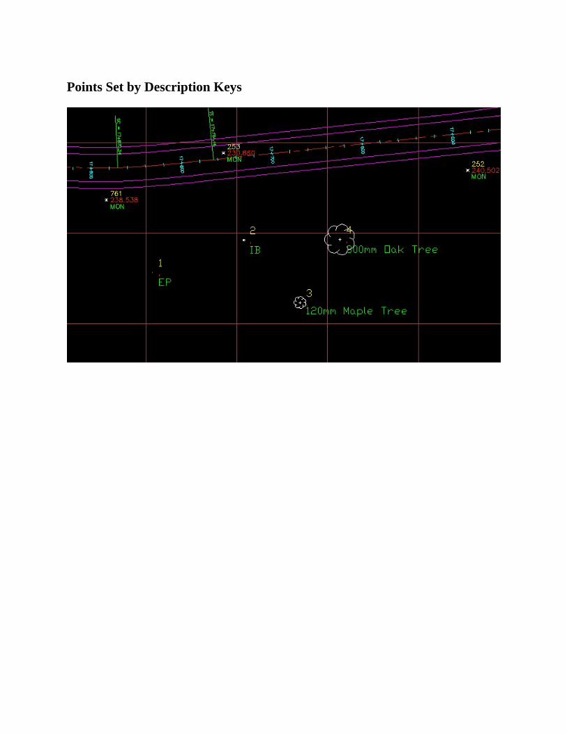
PointsSetbyDescriptionKeys
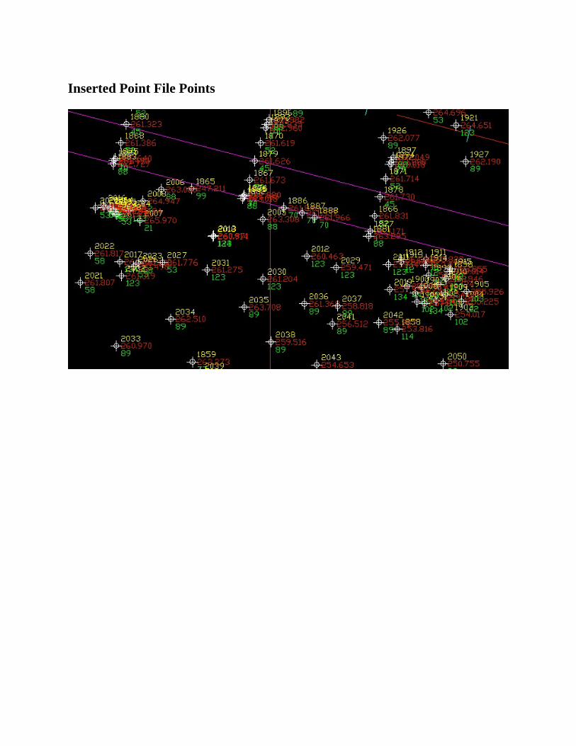
InsertedPointFilePoints
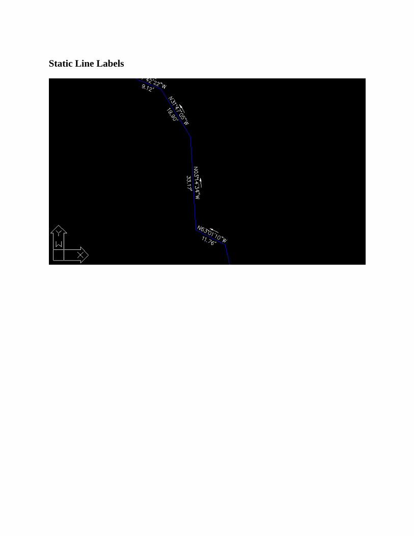
StaticLineLabels

DynamicLineLabels
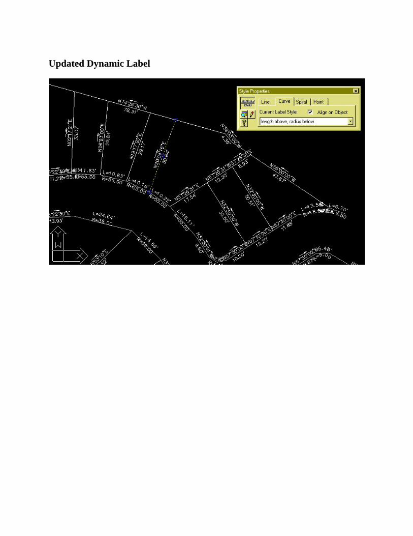
UpdatedDynamicLabel

Non-UpdatedDynamicLabel
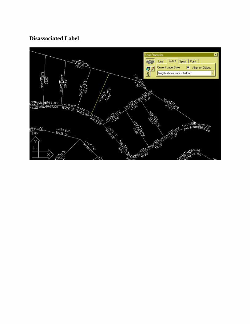
DisassociatedLabel

SwappedLabelText

NewDynamicLabelStyle
!
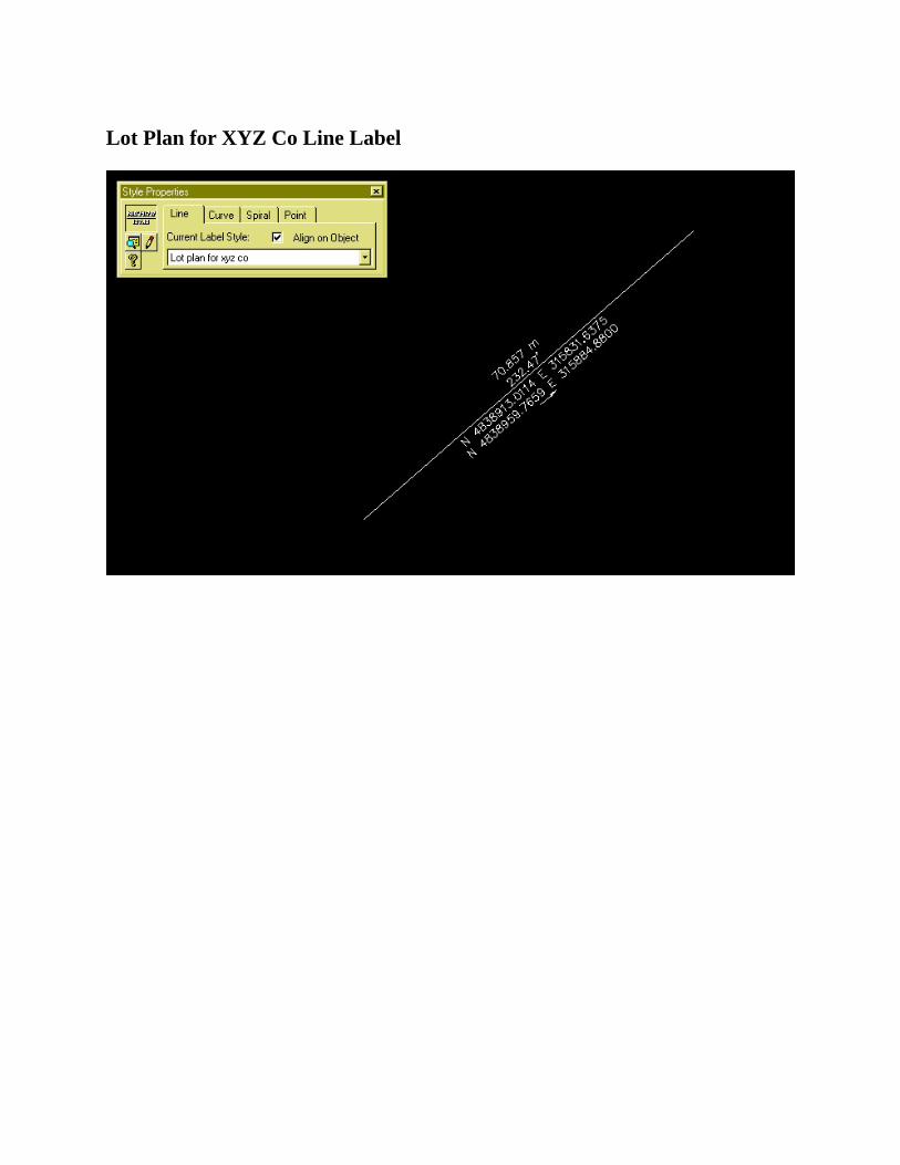
LotPlanforXYZCoLineLabel
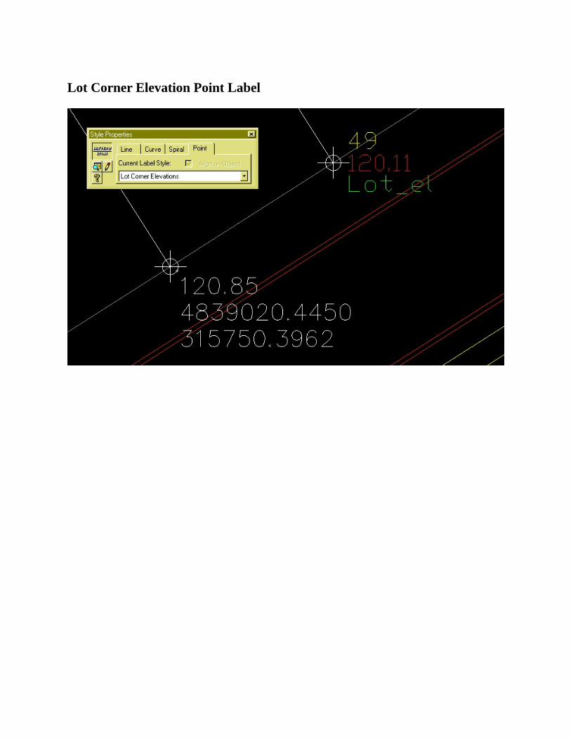
LotCornerElevationPointLabel
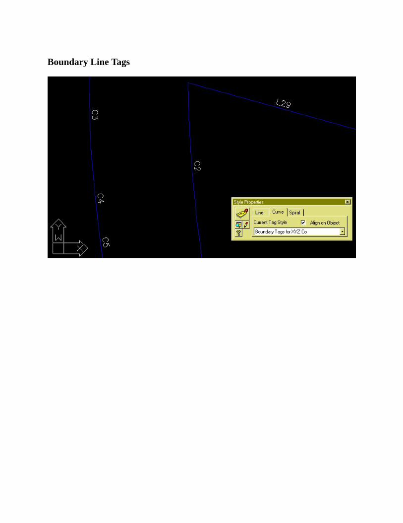
BoundaryLineTags
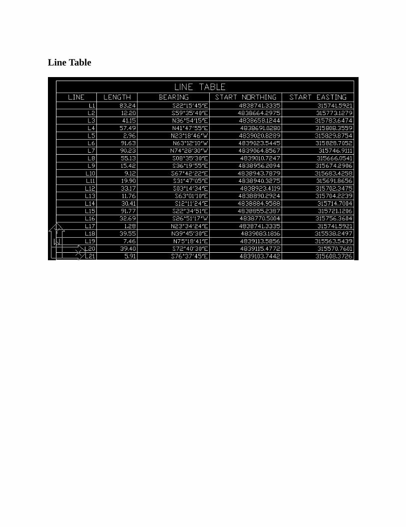
LineTable
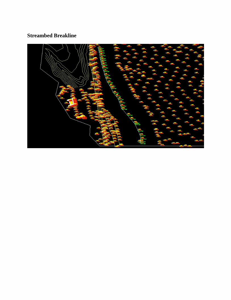
StreambedBreakline
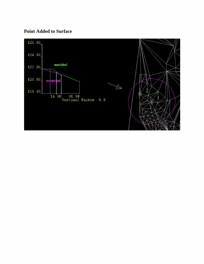
PointAddedtoSurface
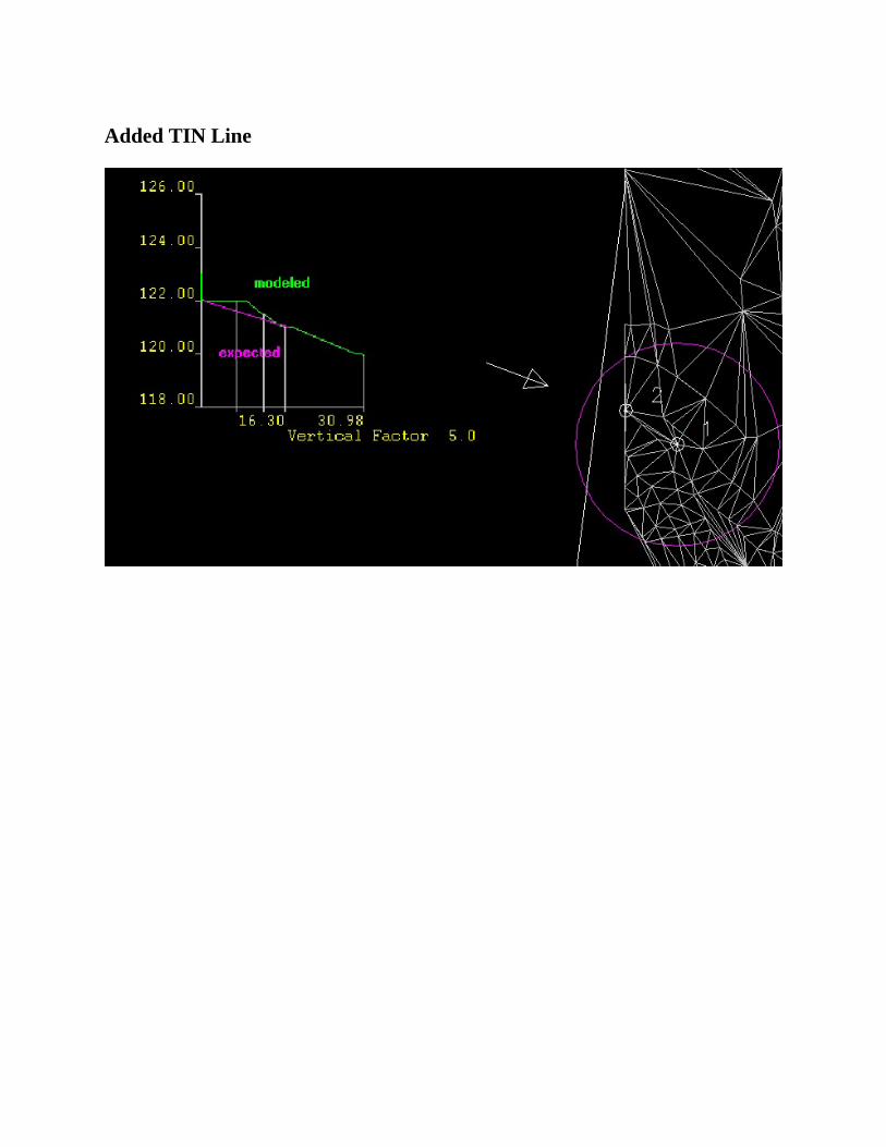
AddedTINLine
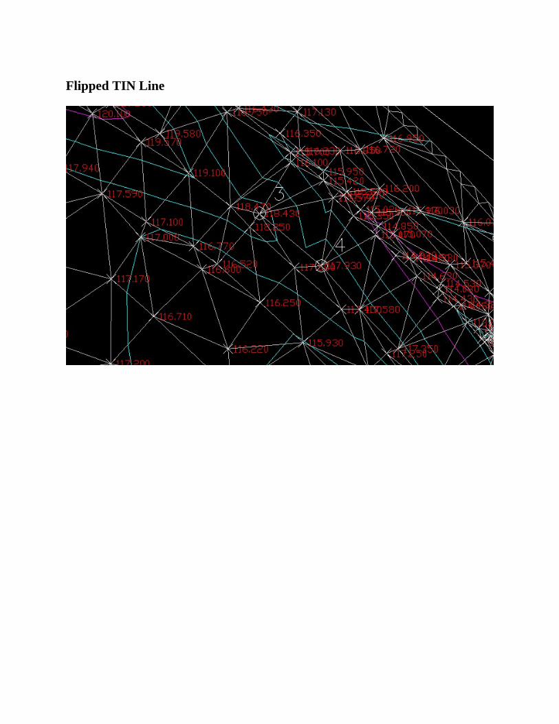
FlippedTINLine
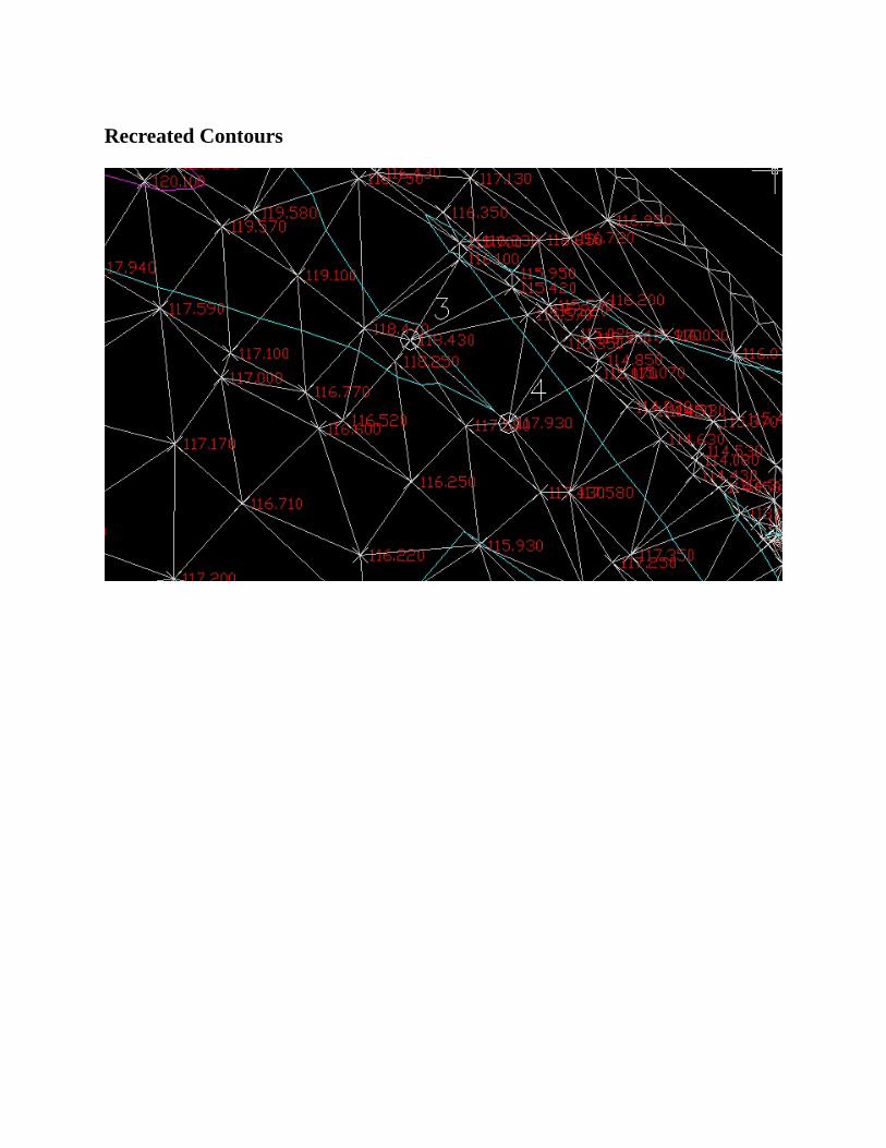
RecreatedContours
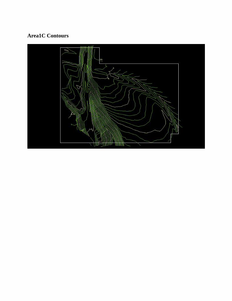
Area1CContours
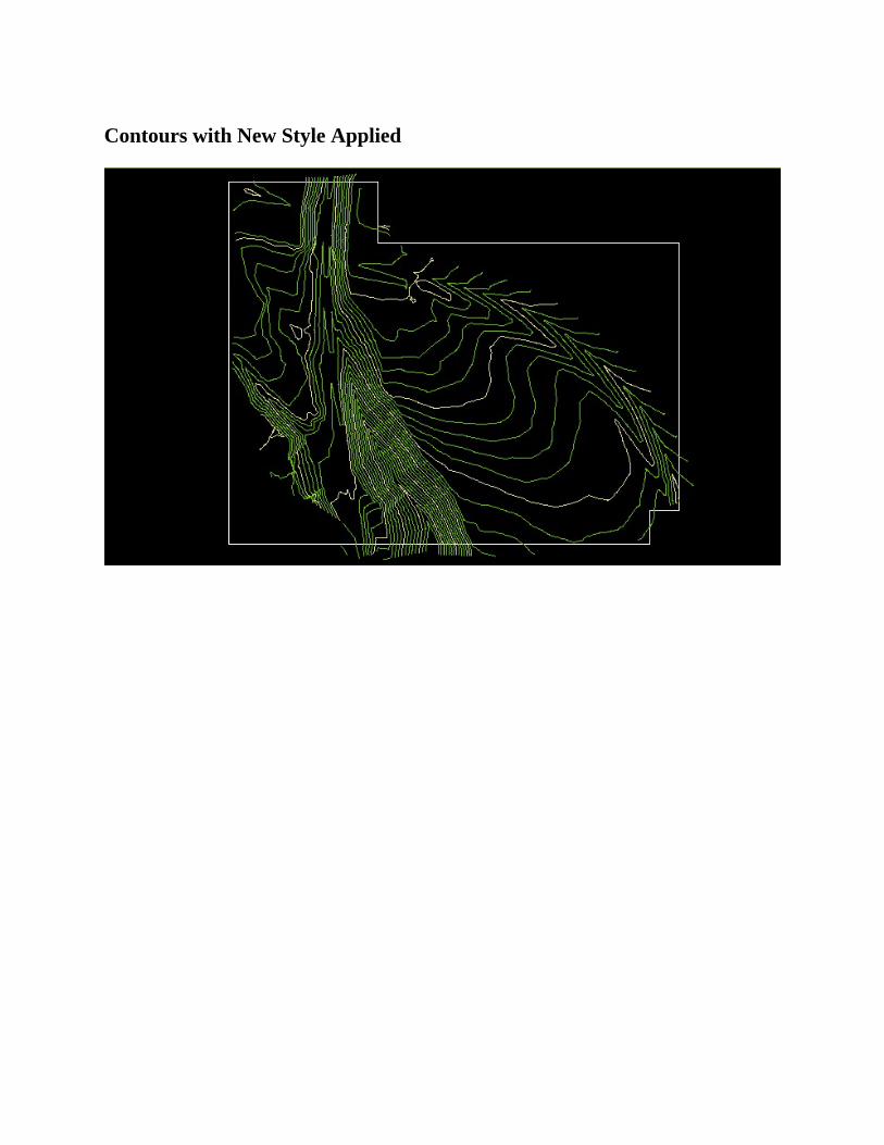
ContourswithNewStyleApplied
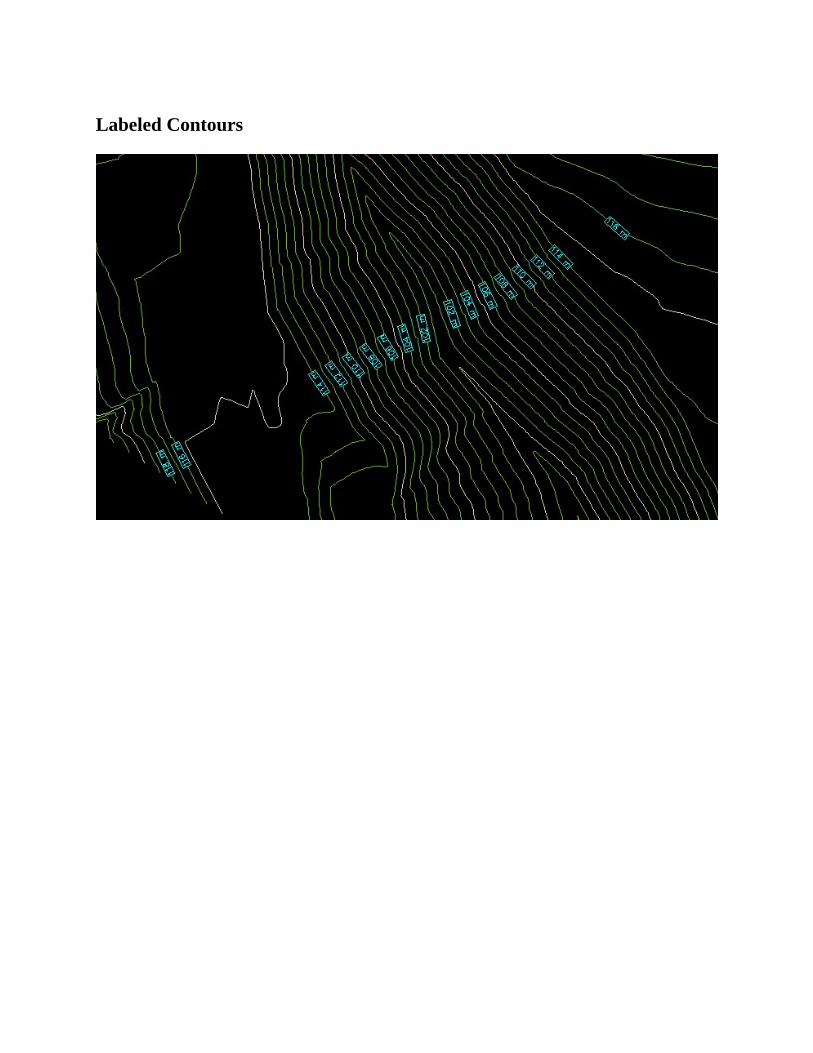
LabeledContours
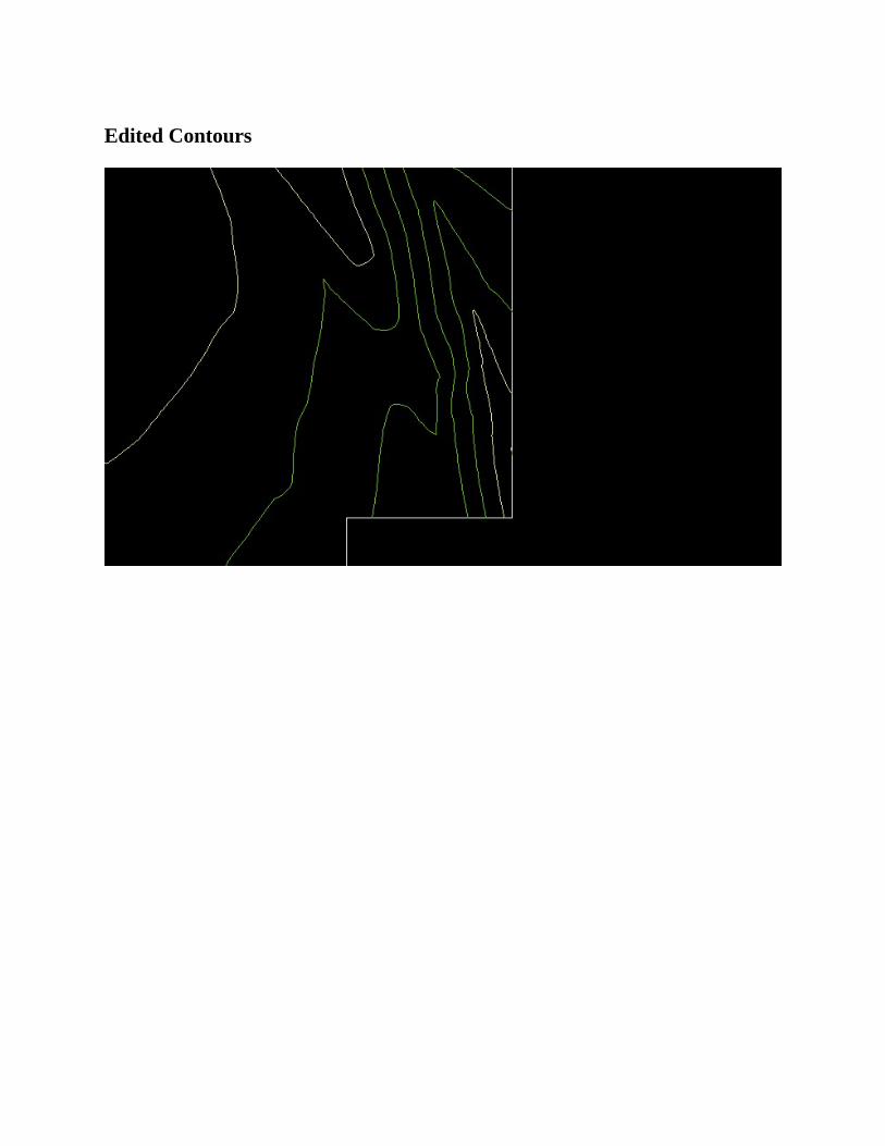
EditedContours
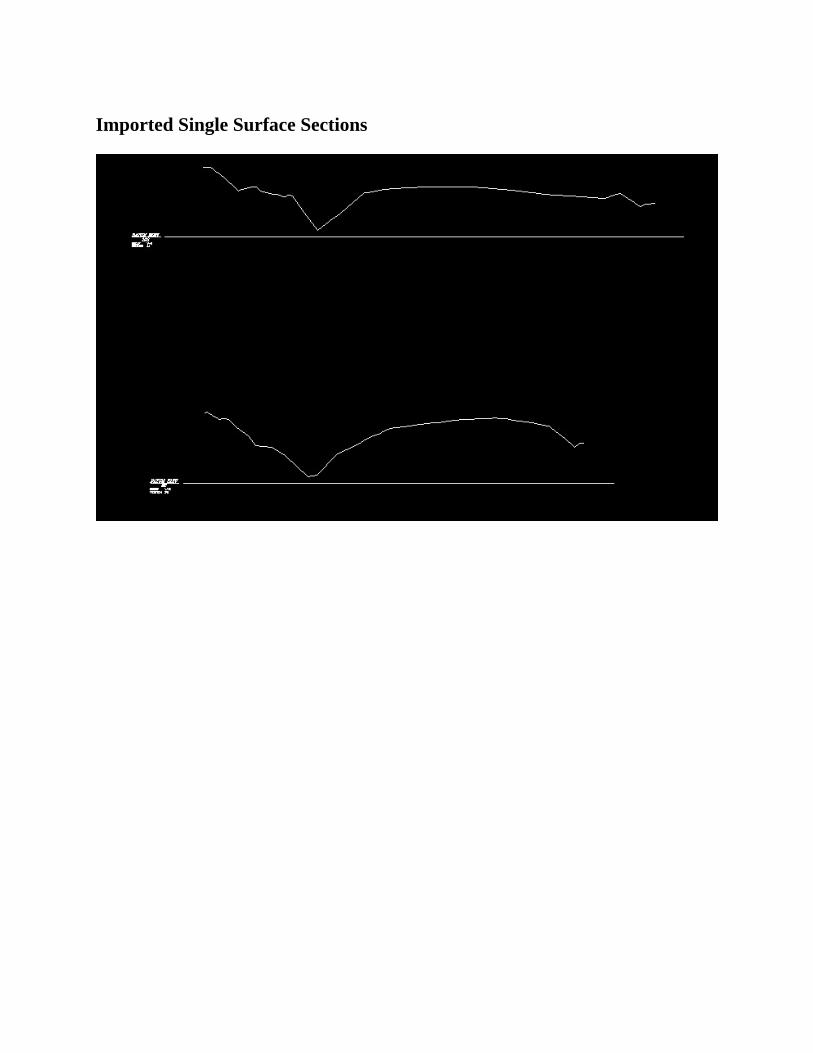
ImportedSingleSurfaceSections
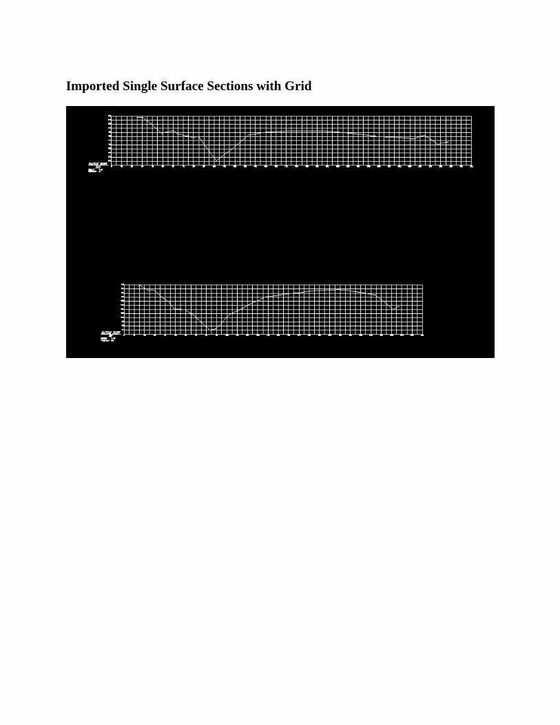
ImportedSingleSurfaceSectionswithGrid
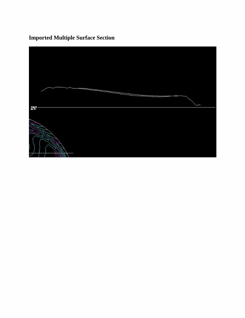
ImportedMultipleSurfaceSection
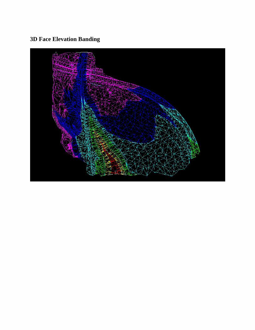
3DFaceElevationBanding
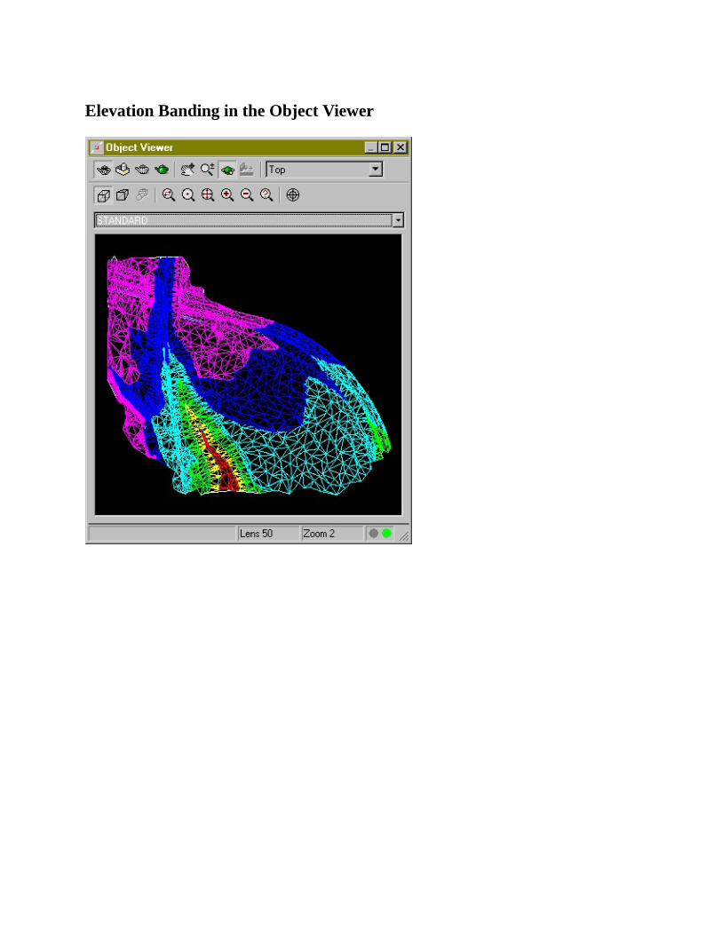
ElevationBandingintheObjectViewer
WatershedBoundaries
WatershedNumbers
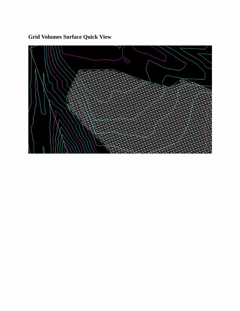
GridVolumesSurfaceQuickView
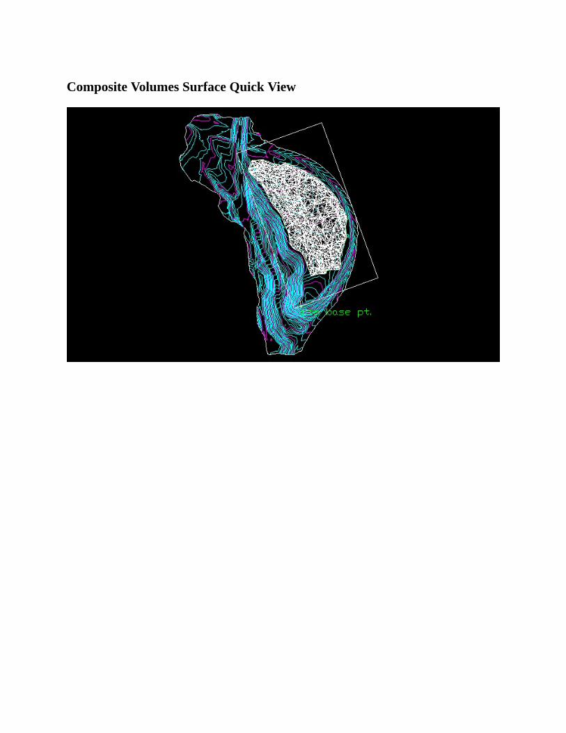
CompositeVolumesSurfaceQuickView
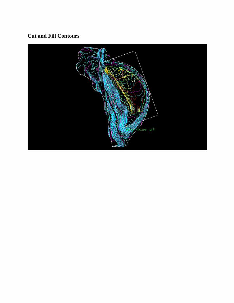
CutandFillContours
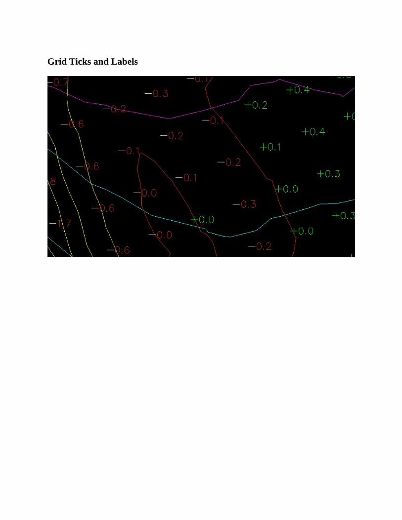
GridTicksandLabels
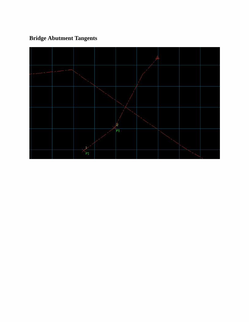
BridgeAbutmentTangents
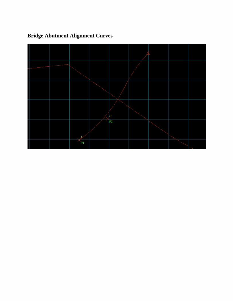
BridgeAbutmentAlignmentCurves
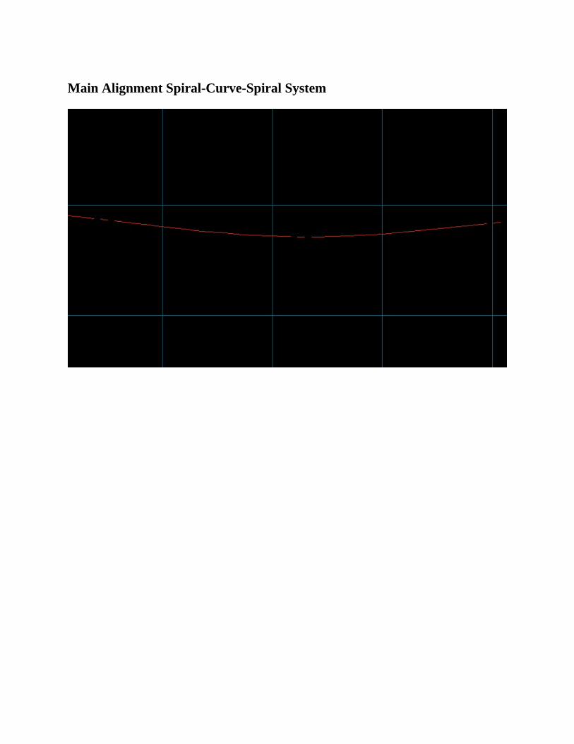
MainAlignmentSpiral-Curve-SpiralSystem
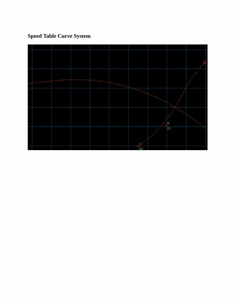
SpeedTableCurveSystem
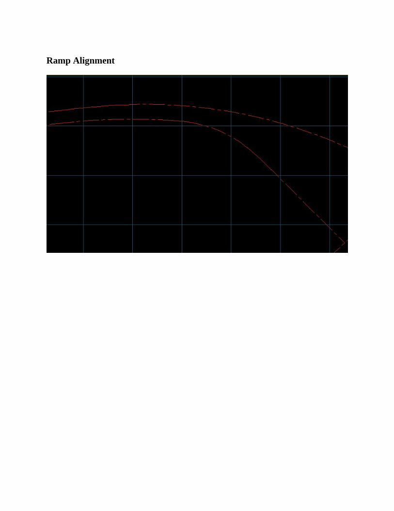
RampAlignment
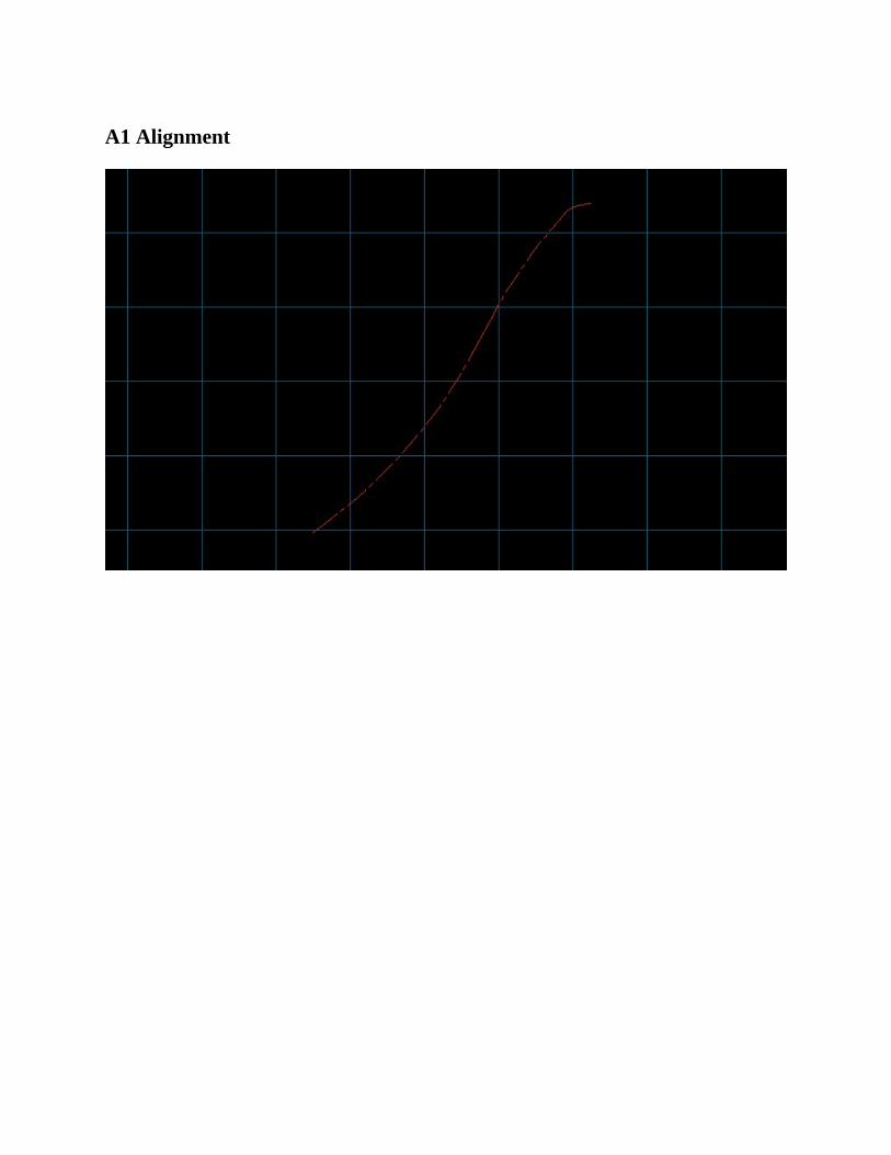
A1Alignment
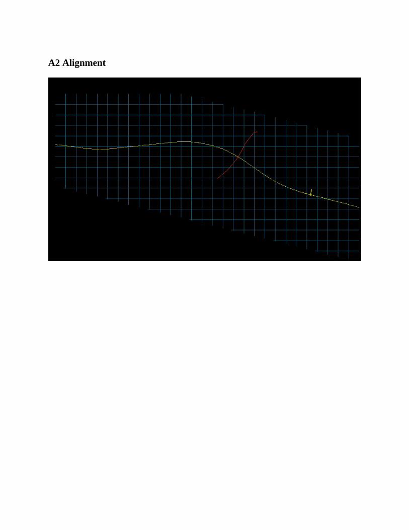
A2Alignment
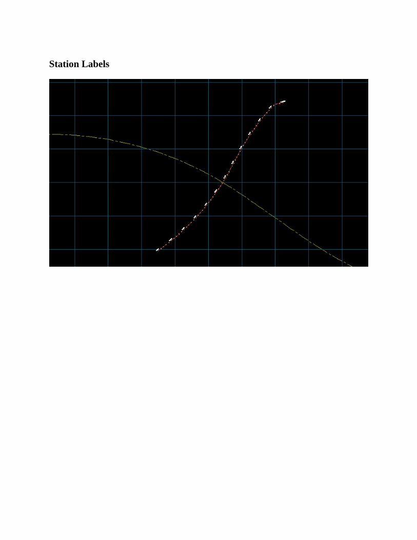
StationLabels
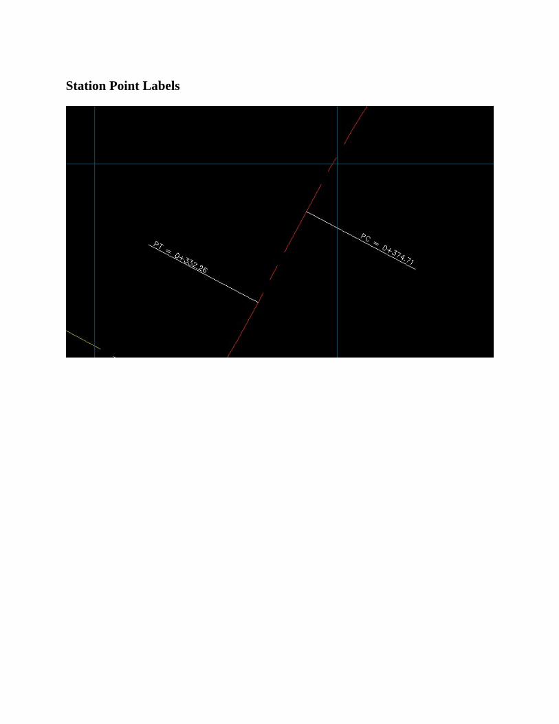
StationPointLabels
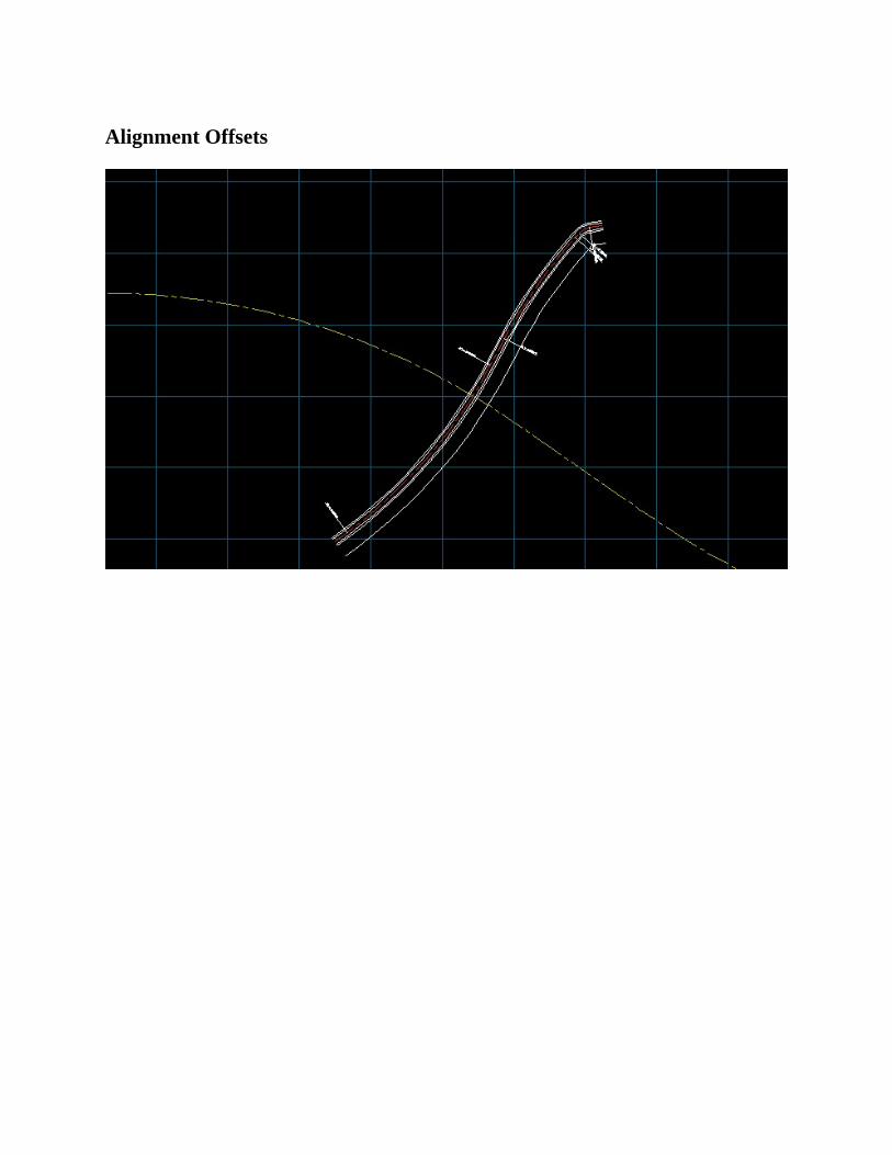
AlignmentOffsets