Embed Size (px)
Citation preview
Be
nu
tz
er
ha
nd
bu
ch
Us
er
m
an
ua
l
HSD
018
0.00
3de
Auswerteelektronik
Evaluation electronics
LVE … / LVX …
2
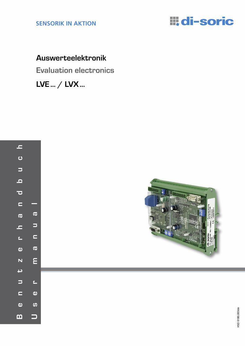
Inhaltsverzeichnis Table of contents Seite / Page
Inhaltsverzeichnis Table of Contents 2/ 3
Sicherheitshinweise Safety instruction 3
Konformität Conformity 3
Kommunikationsschema Communication schematic 4
Technische Daten LVE / LVX LVE LVX technical data 4 / 5
Wichtige Hinweise für Gebrauch und Handhabung Important notes concerning usage and handling
Vorgehensweise Procedure 6
Hinweis Note 6
Selbstabgleich Self calibration 6
LED Zustände bei Selbstabgleich LED states during self calibration 6
Automatische Ausblendung Auto blanking 7
Zulässige Werte Permissible values 7
Funktionen Functions 7
LVE LVE
Kurzbeschreibung LVE LVE Short description 8
Platinenansicht LVE LVE Circuit board and connection diagram 8
Klemmbelegung LVE LVE Terminal pin assignments 9
Technische Daten LVE LVE Technical data 9
Serielle Schnittstelle Serial interface 9
LVX LVX
Kurzbeschreibung LVX LVX Short description 10
Platinenansicht LVX LVX Circuit board and connection diagram 10
DIP-Schalter DIP-Switch 11
Klemmbelegung LVX LVX Terminal pin assignments 11
Technische Daten LVX LVX Technical data 11
Serielle Schnittstelle Serial interface 11
LVx-PBI LVx-PBI
Kurzbeschreibung LVx-PBI LVx-PBI Short description 12
Platinenansicht und Anschlussschema LVx-PBI LVx-PBI Circuit board and connection diagram 12
Klemmbelegung LVx-PBI LVx-PBI Terminal pin assignments 13
Technische Daten LVx-PBI LVx-PBI Technical data 13
Gehäuse LVx-PBI LVx-PBI Housing 13
Belegung des Profibusanschlusses LVx-PBI Pin assignment Profibus 13
Inbetriebnahme LVx-PBI LVx-PBI Start-up 14
Hinweise Notes 14
LEDs LEDs 14
LVx-ALX LVx-ALXKurzbeschreibung LVx-ALX LVx-ALX Short description 16Platinenansicht und Anschlussschema LVx-ALX LVx-ALX Circuit board and connection diagram 16
Klemmbelegung LVx-ALX LVx-ALX Terminal pin assignments 17
Installationshinweis zu LVx-ALX LVx-ALX Installation notes 17
Technische Daten LVx-ALX LVx-ALX Technical data 17
Gehäuse LVx-ALX LVx-ALX Housing 17
3
GEFAHRDie Lichtgitter sind keine zertifizierten Sicherheitslichtgitter nach EN 61496. Sie sind keine Sicherheitsbauteile im Sinne der EG-Maschinenrichtlinie 89/392/EWG mit Ergänzung 93/44/EMW, Anhang 4. Sie dürfen daher nicht eingesetzt werden, um Gefahren von Personen abzuwenden.Die Handhabung des Gerätes und das An- und Abklemmen von Leitungen ist nur bei abgeschalteter Betriebsspannung zulässig. Der Einsatz dieser Geräte muss durch Fachpersonal erfolgen. Die Geräte sind nicht zulässig für Sicherheitsanwendungen, insbesondere bei denen die Sicherheit von Personen von der Gerätefunktion abhängig ist.
Alle technischen Angaben beziehen sich auf den Stand 11/10, Änderungen bleiben vorbehalten. Da Irrtümer und Druckfehler nicht auszuschließen sind, gilt für alle Angaben „ohne Gewähr“.
DANGERThe light screens are not certified security light screens according toEN 61496. They are not safety components in accordance with EU machine guidelines 89/392/EWG with supplement 93/44/EMW appendix 4.These components are therefore not to be used to prevent danger to person-nel. Handling of the devices and connecting/disconnecting lines isonly permitted with the operating voltage switched off. These instruments shall exclusively be used by qualified personnel. The instruments are not to be used for safety applications, in particular applications in which safety of persons depends on proper operation of the instruments.
All technical specifications refer to the state of the art 11/10, they are subject to modifications. As typographical and other errors cannot be excluded, all data are given „without engagement“.
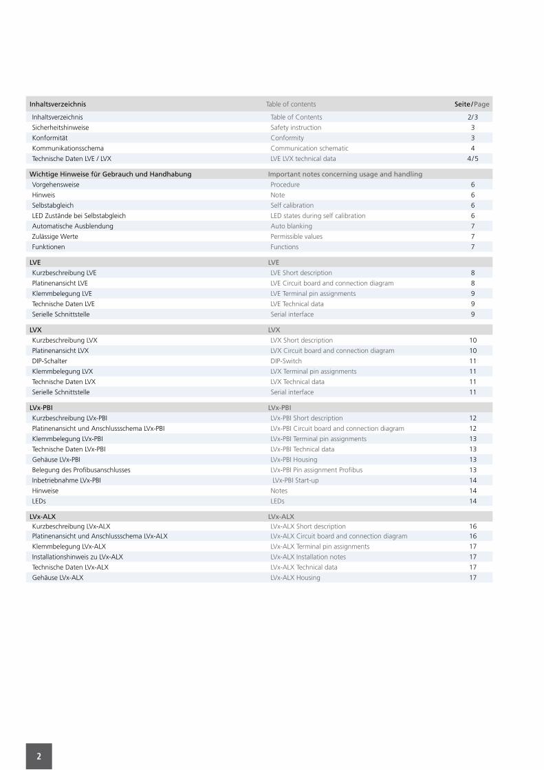
LVx-ALM LVx-ALM
Kurzbeschreibung LVx-ALM LVx-ALM Short description 18
Platinenansicht und Anschlussschema LVx-ALM LVx-ALM Circuit board and connection diagram 18
Klemmbelegung LVx-ALM LVx-ALM Terminal pin assignments 19
Technische Daten LVx-ALM LVx-ALM Technical data 19
Gehäuse LVx-ALM LVx-ALM Housing 19
Hinweise Notes 19
LVx-ALM / PBI LVx-ALM / PBI
Kurzbeschreibung LVx-ALM / PBI LVx-ALM / PBI Short description 20
Platinenansicht und Anschlussschema LVx-ALM / PBI LVx-ALM / PBI Circuit board and connection diagram 20
LVx-O16 LVx-O16
Kurzbeschreibung LVx-O16 LVx-O16 Short description 22
Platinenansicht und Anschlussschema LVx-O16 LVx-O16 Circuit board and connection diagram 22
Klemmbelegung LVx-O16 LVx-O16 Terminal pin assignments 23
Technische Daten LVx-O16 LVx-O16 Technical data 23
Gehäuse LVx-O16 LVx-O16 Housing 23
LEDs LEDs 24
LED A LED A 24
LED B LED B 24
Fehler-LEDs Fault LEDs 24
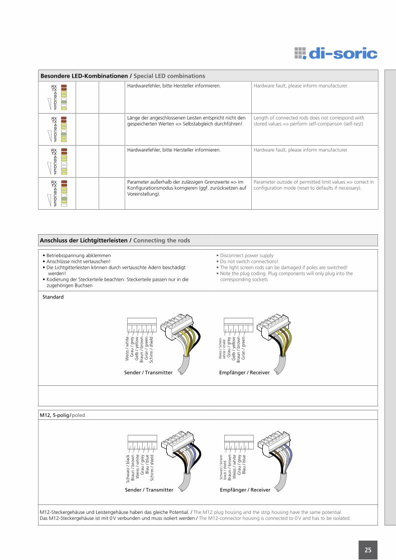
Besondere LED-Kombinationen Special LED combinations 25
Anschluss der Lichtgitterleisten Connecting the rods 25
KonformitätLichtgittersysteme bestehend aus Leistenpaar Typ LI und Auswertegerät LVX tragen das -Kennzeichen und erfüllen die Anforderungen folgender Normen: Störaussendung: EN 61000-6-3:2001. Störfestigkeit: EN 61000-6-1:2001.
ConformityLight screen systems consisting of wire-pair type LI and controller LVX carry the -stamp and meet the requirements of the following standards:
Emitted interference: EN 61000-6-3:2001. Interference resistance: EN 61000-6-1:2001.
4
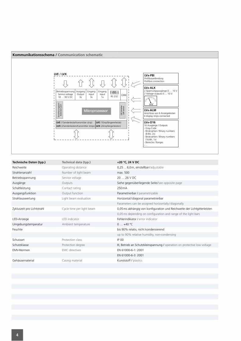
Technische Daten (typ.) Technical data (typ.) +20 °C, 24 V DC
Reichweite Operating distance 0,25 … 6,0 m, einstellbar / adjustable
Strahlenanzahl Number of light beam max. 500
Betriebsspannung Service voltage 20 … 26 V DC
Ausgänge Outputs Siehe gegenüberliegende Seite / see opposite page
Schaltleistung Contact rating 250 mA
Ausgangsfunktion Output function Parametrierbar / parametrizable
Strahlauswertung Light beam evaluation Horizontal / diagonal parametrierbar
Parameters can be assigned horizontally / diagonally
Zykluszeit pro Lichtstrahl Cycle time per light beam 0,05 ms abhängig von konfiguration und Reichweite der Lichtgitterleisten
0,05 ms depending on configuration and range of the light bars
LED-Anzeige LED indicator Fehlerindikator / error indicator
Umgebungstemperatur Ambient temperature 0 … +40 °C
Feuchte bis 90% relativ, nicht kondensierend
up to 90% relative humidity, non-condensing
Schutzart Protection class IP 00
Schutzklasse Protection degree III, Betrieb an Schutzkleinspannung / operation on protective low voltage
EMV-Normen EMC directives EN 61000-6-1: 2001
EN 61000-6-3: 2001
Gehäusematerial Casing material Kunststoff / plastics
Kommunikationsschema / Communication schematic
LVx-O1616 Ausgänge / Outputs- Gray-Code- Binärzahlen / Binary numbers (8-Bit, 2x)- Binärzahlen / Binary numbers (16-Bit, 1x)- Bereiche / Ranges- ...
LVx-PBIProfibusanbindungProfibus connection
LVx-ALMAnschluss von 6 Anzeigeleisten6 display strips connected
LVx-ALX2 Spannungsausgänge 0 … 10 V2 Voltage outputs 0 … 10 V
BetriebsspannungService voltage18 … 30 V DC
AusgangOutput
3x
EingangInput
3x
EingangInput
1x RS 232
LVE (1Senderleiste/transmitter strip)
LVX (2Senderleisten/transmitter strips)
LVE (1Empfängererleiste)
LVX (2Empfängerleisten)
LVE / LVX
Erw
eite
run
gsp
ort
Exte
nsi
on
po
rt
DIP
Sch
alte
rD
IP s
wit
ch
5
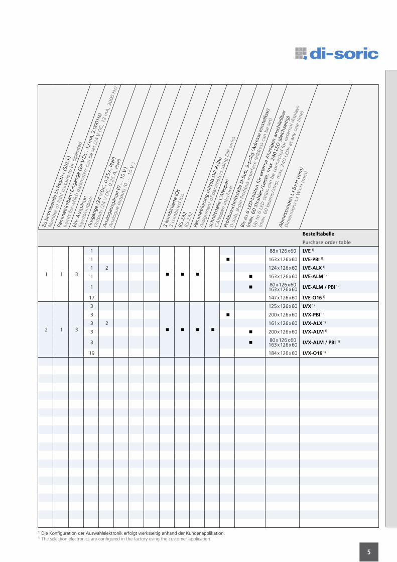
Bestelltabelle
Purchase order table
1 1 3
1
88 x 126 x 60 LVE 1)
1 163 x 126 x 60 LVE-PBI 1)
1 2 124 x 126 x 60 LVE-ALX 1)
1 163 x 126 x 60 LVE-ALM 1)
1 80 x 126 x 60 163 x 126 x 60 LVE-ALM / PBI 1)
17 147 x 126 x 60 LVE-O16 1)
2 1 3
3
125 x 126 x 60 LVX 1)
3 200 x 126 x 60 LVX-PBI 1)
3 2 161 x 126 x 60 LVX-ALX 1)
3 200 x 126 x 60 LVX-ALM 1)
3 80 x 126 x 60 163 x 126 x 60 LVX-ALM / PBI 1)
19 184 x 126 x 60 LVX-O16 1)
Zu b
etre
iben
de
Lich
tgitte
r (S
tück
)
Num
ber
of
light
curt
ains
to b
e oper
ated
Para
met
rier
bar
e Ei
ngän
ge
(24 V
DC
, 12 m
A, 3
.000 H
z)
Inpu
ts for
whi
ch p
aram
eter
s ca
n be
set
(24
V D
C, 1
2 m
A, 3
000
Hz)
Ein-
Ausg
änge
Inputs
/outp
uts
Ausg
änge
(24 V
DC
, 0,2
5 A
, PN
P)
Outp
uts
(24 V
DC
, 0.2
5 A
, PN
P)
Anal
ogau
sgän
ge
(0 …
10 V
)
Anal
ogue
outp
uts
(0 …
10 V
)
3 k
om
bin
iert
e IO
s
3 c
om
bin
ed IO
sRS
232
RS
232
Para
met
rier
ung m
itte
ls D
IP R
eihe
Ass
ignm
ent
of
par
amet
ers
usi
ng D
IP s
erie
s
Schnitts
telle
CA
Nopen
CA
Nopen
inte
rfac
ePr
ofibuss
chnitts
telle
D-S
ub, 9-p
olig
(A
dre
sse
einst
ellb
ar)
D-S
ub, 9-p
in P
rofibus
inte
rfac
e (a
ddre
ss c
an b
e se
t)
Bis
zu 6
LED
-Lei
sten
für
exte
rne
Anze
igen
ansc
hlie
ßbar
(max
. 60 S
trah
len / L
eist
e, m
ax. 240 L
ED g
leic
hze
itig
)
Up t
o 6
LED
str
ips
can b
e co
nnec
ted f
or
exte
rnal
dis
pla
ys
(max
. 60 b
eam
s / st
rip, m
ax. 240 L
EDs
at a
ny
one
tim
e)
Abm
essu
ngen
L x B
x H
(m
m)
Dim
ensi
ons
L x W
x H
(m
m)
1) Die Konfiguration der Auswahlelektronik erfolgt werksseitig anhand der Kundenapplikation.1) The selection electronics are configured in the factory using the customer application.
6
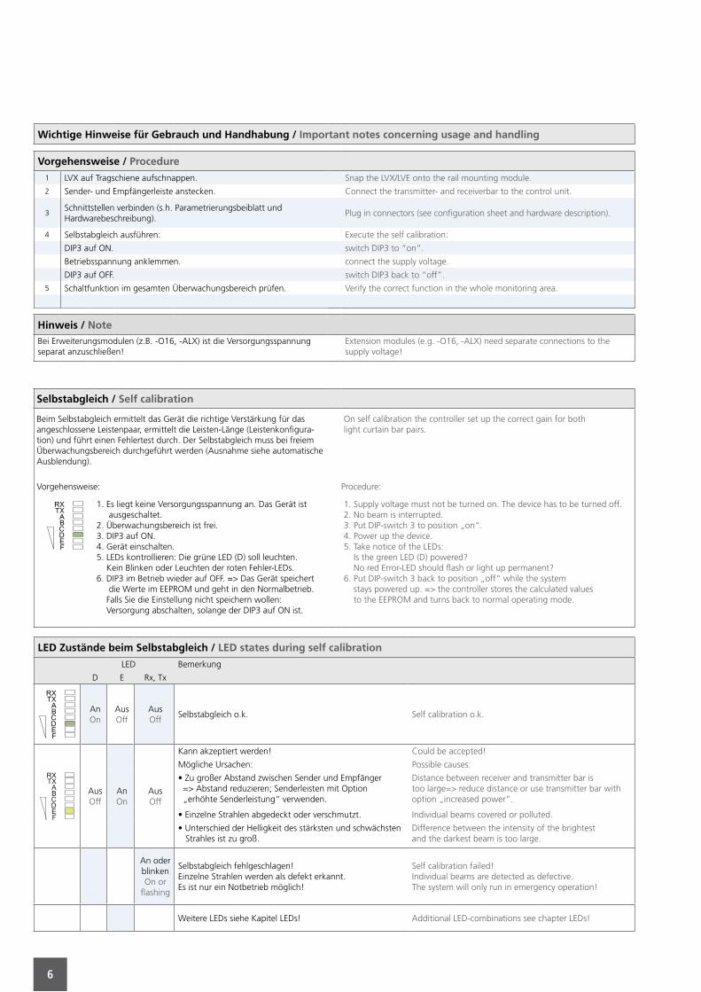
Wichtige Hinweise für Gebrauch und Handhabung / Important notes concerning usage and handling
Vorgehensweise / Procedure1 LVX auf Tragschiene aufschnappen. Snap the LVX/LVE onto the rail mounting module.
2 Sender- und Empfängerleiste anstecken. Connect the transmitter- and receiverbar to the control unit.
3Schnittstellen verbinden (s.h. Parametrierungsbeiblatt undHardwarebeschreibung).
Plug in connectors (see configuration sheet and hardware description).
4 Selbstabgleich ausführen: Execute the self calibration:
DIP3 auf ON. switch DIP3 to “on”.
Betriebsspannung anklemmen. connect the supply voltage.
DIP3 auf OFF. switch DIP3 back to “off”.
5 Schaltfunktion im gesamten Überwachungsbereich prüfen. Verify the correct function in the whole monitoring area.
Hinweis / NoteBei Erweiterungsmodulen (z.B. -O16, -ALX) ist die Versorgungsspannung separat anzuschließen!
Extension modules (e.g. -O16, -ALX) need separate connections to the supply voltage!
Selbstabgleich / Self calibration
Beim Selbstabgleich ermittelt das Gerät die richtige Verstärkung für das angeschlossene Leistenpaar, ermittelt die Leisten-Länge (Leistenkonfigura-tion) und führt einen Fehlertest durch. Der Selbstabgleich muss bei freiem Überwachungsbereich durchgeführt werden (Ausnahme siehe automatische Ausblendung).
On self calibration the controller set up the correct gain for bothlight curtain bar pairs.
Vorgehensweise: Procedure:
1. Es liegt keine Versorgungsspannung an. Das Gerät ist ausgeschaltet.2. Überwachungsbereich ist frei.3. DIP3 auf ON.4. Gerät einschalten.5. LEDs kontrollieren: Die grüne LED (D) soll leuchten. Kein Blinken oder Leuchten der roten Fehler-LEDs.6. DIP3 im Betrieb wieder auf OFF. => Das Gerät speichert die Werte im EEPROM und geht in den Normalbetrieb. Falls Sie die Einstellung nicht speichern wollen: Versorgung abschalten, solange der DIP3 auf ON ist.
1. Supply voltage must not be turned on. The device has to be turned off.2. No beam is interrupted.3. Put DIP-switch 3 to position „on“.4. Power up the device.5. Take notice of the LEDs: Is the green LED (D) powered? No red Error-LED should flash or light up permanent?6. Put DIP-switch 3 back to position „off“ while the system stays powered up. => the controller stores the calculated values to the EEPROM and turns back to normal operating mode.
LED Zustände beim Selbstabgleich / LED states during self calibration
LED Bemerkung
D E Rx, Tx
AnOn
AusOff
AusOff
Selbstabgleich o.k. Self calibration o.k.
AusOff
AnOn
AusOff
Kann akzeptiert werden! Could be accepted!
Mögliche Ursachen: Possible causes:
• Zu großer Abstand zwischen Sender und Empfänger => Abstand reduzieren; Senderleisten mit Option „erhöhte Senderleistung“ verwenden.
Distance between receiver and transmitter bar istoo large=> reduce distance or use transmitter bar withoption „increased power“.
• Einzelne Strahlen abgedeckt oder verschmutzt. Individual beams covered or polluted.
• Unterschied der Helligkeit des stärksten und schwächsten Strahles ist zu groß.
Difference between the intensity of the brightestand the darkest beam is too large.
An oder blinkenOn or
flashing
Selbstabgleich fehlgeschlagen!Einzelne Strahlen werden als defekt erkannt.Es ist nur ein Notbetrieb möglich!
Self calibration failed!Individual beams are detected as defective.The system will only run in emergency operation!
Weitere LEDs siehe Kapitel LEDs! Additional LED-combinations see chapter LEDs!
7
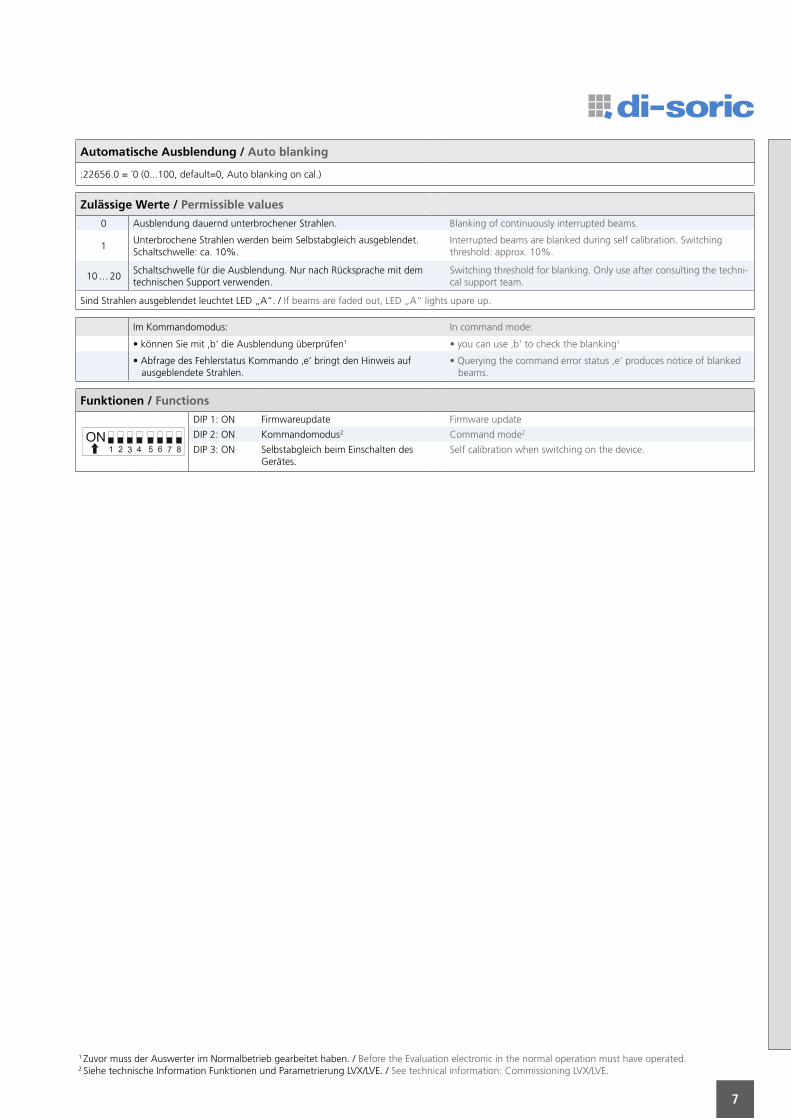
Automatische Ausblendung / Auto blanking
:22656.0 = ´0 (0...100, default=0, Auto blanking on cal.)
Zulässige Werte / Permissible values
0 Ausblendung dauernd unterbrochener Strahlen. Blanking of continuously interrupted beams.
1Unterbrochene Strahlen werden beim Selbstabgleich ausgeblendet.Schaltschwelle: ca. 10%.
Interrupted beams are blanked during self calibration. Switching threshold: approx. 10%.
10 … 20Schaltschwelle für die Ausblendung. Nur nach Rücksprache mit dem technischen Support verwenden.
Switching threshold for blanking. Only use after consulting the techni-cal support team.
Sind Strahlen ausgeblendet leuchtet LED „A“. / If beams are faded out, LED „A“ lights upare up.
Im Kommandomodus: In command mode:
• können Sie mit ‚b‘ die Ausblendung überprüfen1 • you can use ‚b‘ to check the blanking1
• Abfrage des Fehlerstatus Kommando ‚e’ bringt den Hinweis auf ausgeblendete Strahlen.
• Querying the command error status ‚e‘ produces notice of blanked beams.
Funktionen / Functions
DIP 1: ON Firmwareupdate Firmware update
DIP 2: ON Kommandomodus2 Command mode2
DIP 3: ON Selbstabgleich beim Einschalten des Gerätes.
Self calibration when switching on the device.
1 Zuvor muss der Auswerter im Normalbetrieb gearbeitet haben. / Before the Evaluation electronic in the normal operation must have operated.2 Siehe technische Information Funktionen und Parametrierung LVX/LVE. / See technical information: Commissioning LVX/LVE.
8
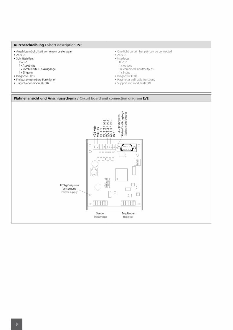
Kurzbeschreibung / Short description LVE
• Anschlussmöglichkeit von einem Leistenpaar• 24 V DC• Schnittstellen: RS232 1 x Ausgänge 3 x kombinierte Ein-Ausgänge 1 x Eingang• Diagnose LEDs• Frei parametrierbare Funktionen• Tragschienenmodul (IP 00)
• One light curtain bar pair can be connected• 24 V DC• Interfaces: RS232 1 x output 3 x combined input/outputs 1 x input• Diagnostic LEDs• Parameter definable functions• Support rod module (IP 00)
Platinenansicht und Anschlussschema / Circuit board and connection diagram LVE
SenderTransmitter
EmpfängerReceiver
LED grün/greenVersorgung
Power supply
LED
grü
n/gr
een
Stat
us E
in-/
Ausg
änge
Stat
us in
put/
outp
ut
9
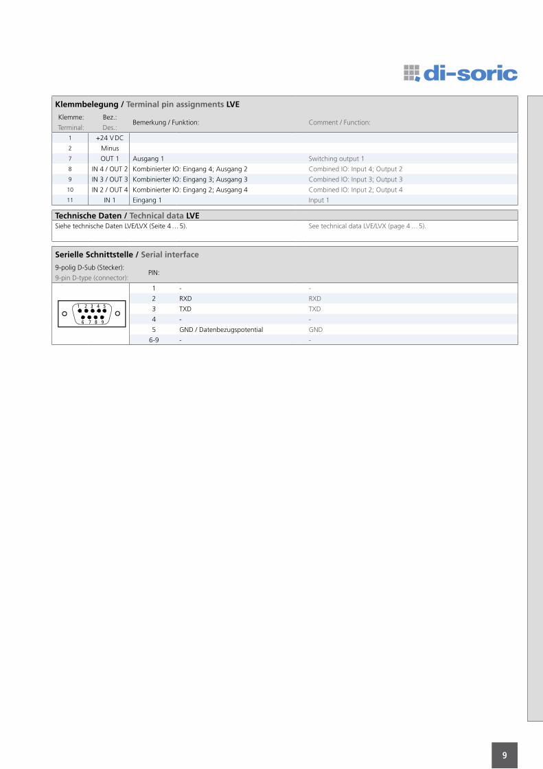
Klemmbelegung / Terminal pin assignments LVE
Klemme: Bez.:Bemerkung / Funktion: Comment / Function:
Terminal: Des.:
1 +24 V DC
2 Minus
7 OUT 1 Ausgang 1 Switching output 1
8 IN 4 / OUT 2 Kombinierter IO: Eingang 4; Ausgang 2 Combined IO: Input 4; Output 2
9 IN 3 / OUT 3 Kombinierter IO: Eingang 3; Ausgang 3 Combined IO: Input 3; Output 3
10 IN 2 / OUT 4 Kombinierter IO: Eingang 2; Ausgang 4 Combined IO: Input 2; Output 4
11 IN 1 Eingang 1 Input 1
Technische Daten / Technical data LVESiehe technische Daten LVE/LVX (Seite 4 … 5). See technical data LVE/LVX (page 4 … 5).
Serielle Schnittstelle / Serial interface
9-polig D-Sub (Stecker):PIN:
9-pin D-type (connector):
1 3 42 5
6 987
1 - -
2 RXD RXD
3 TXD TXD
4 - -
5 GND / Datenbezugspotential GND
6-9 - -
10
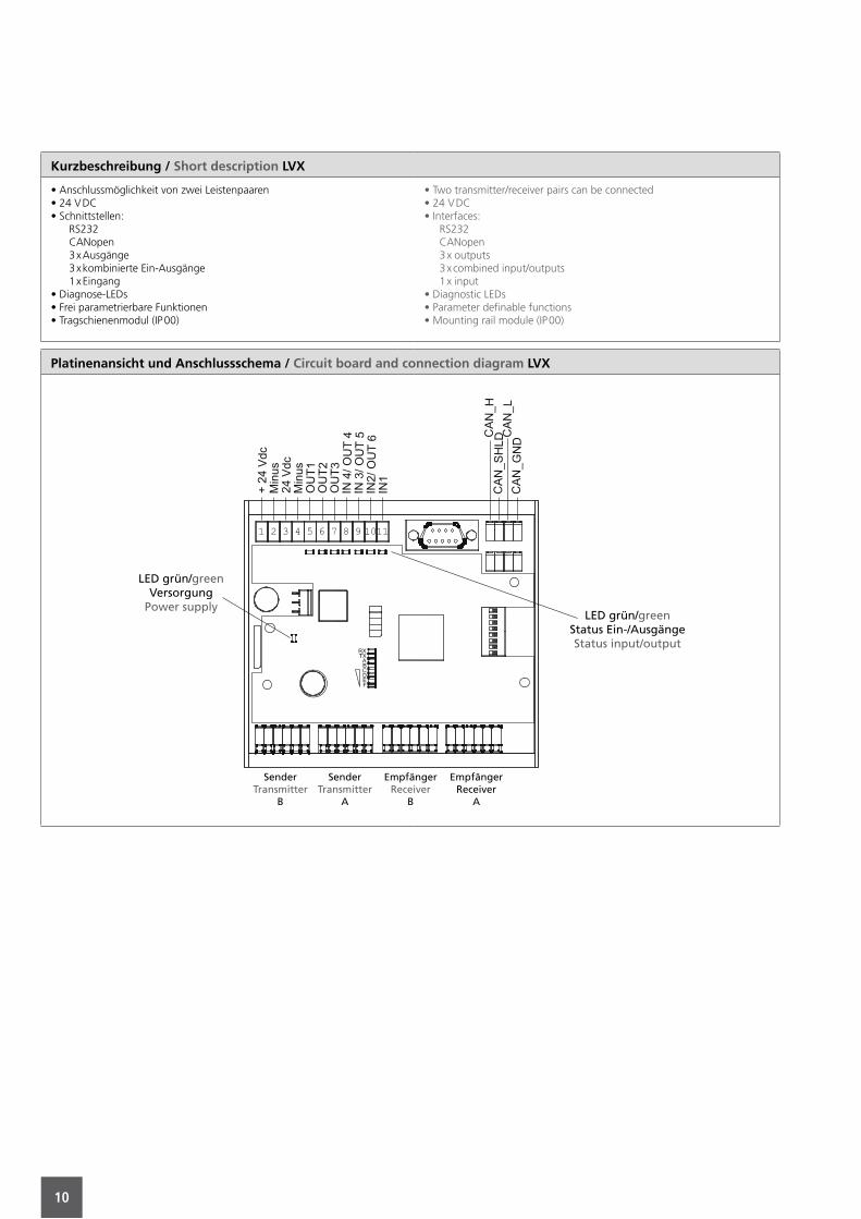
Kurzbeschreibung / Short description LVX
• Anschlussmöglichkeit von zwei Leistenpaaren• 24 V DC• Schnittstellen: RS232 CANopen 3 x Ausgänge 3 x kombinierte Ein-Ausgänge 1 x Eingang• Diagnose-LEDs• Frei parametrierbare Funktionen• Tragschienenmodul (IP 00)
• Two transmitter/receiver pairs can be connected• 24 V DC• Interfaces: RS232 CANopen 3 x outputs 3 x combined input/outputs 1 x input• Diagnostic LEDs• Parameter definable functions• Mounting rail module (IP 00)
Platinenansicht und Anschlussschema / Circuit board and connection diagram LVX
SenderTransmitter
B
EmpfängerReceiver
A
EmpfängerReceiver
B
SenderTransmitter
A
LED grün/greenStatus Ein-/AusgängeStatus input/output
LED grün/greenVersorgung
Power supply
11
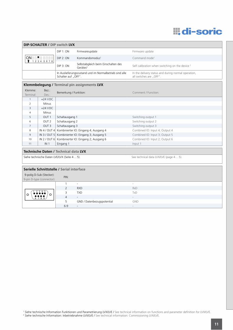
DIP-SCHALTER / DIP switch LVX
DIP 1: ON Firmwareupdate Firmware update
DIP 2: ON Kommandomodus1 Command mode1
DIP 3: ONSelbstabgleich beim Einschalten des Gerätes2 Self calibration when switching on the device 2
In Auslieferungszustand und im Normalbetrieb sind alle Schalter auf „OFF“.
In the delivery status and during normal operation,all switches are „OFF“.
Klemmbelegung / Terminal pin assignments LVX
Klemme: Bez.:Bemerkung / Funktion: Comment / Function:
Terminal: Des.:
1 +24 V DC
2 Minus
3 +24 V DC
4 Minus
5 OUT 1 Schaltausgang 1 Switching output 1
6 OUT 2 Schaltausgang 2 Switching output 2
7 OUT 3 Schaltausgang 3 Switching output 3
8 IN 4 / OUT 4 Kombinierter IO: Eingang 4; Ausgang 4 Combined IO: Input 4; Output 4
9 IN 3 / OUT 5 Kombinierter IO: Eingang 3; Ausgang 5 Combined IO: Input 3; Output 5
10 IN 2 / OUT 6 Kombinierter IO: Eingang 2; Ausgang 6 Combined IO: Input 2; Output 6
11 IN 1 Eingang 1 Input 1
Technische Daten / Technical data LVX
Siehe technische Daten LVE/LVX (Seite 4 … 5). See technical data LVX/LVE (page 4 … 5).
Serielle Schnittstelle / Serial interface
9-polig D-Sub (Stecker):PIN:
9-pin D-type (connector):
1 3 42 5
6 987
1 - -
2 RXD RxD
3 TXD TxD
4 - -
5 GND / Datenbezugspotential GND
6-9 - -
1 Siehe technische Information Funktionen und Parametrierung LVX/LVE / See technical information on functions and parameter definition for LVX/LVE.2 Siehe technische Information: Inbetriebnahme LVX/LVE / See technical information: Commissioning LVX/LVE.
12
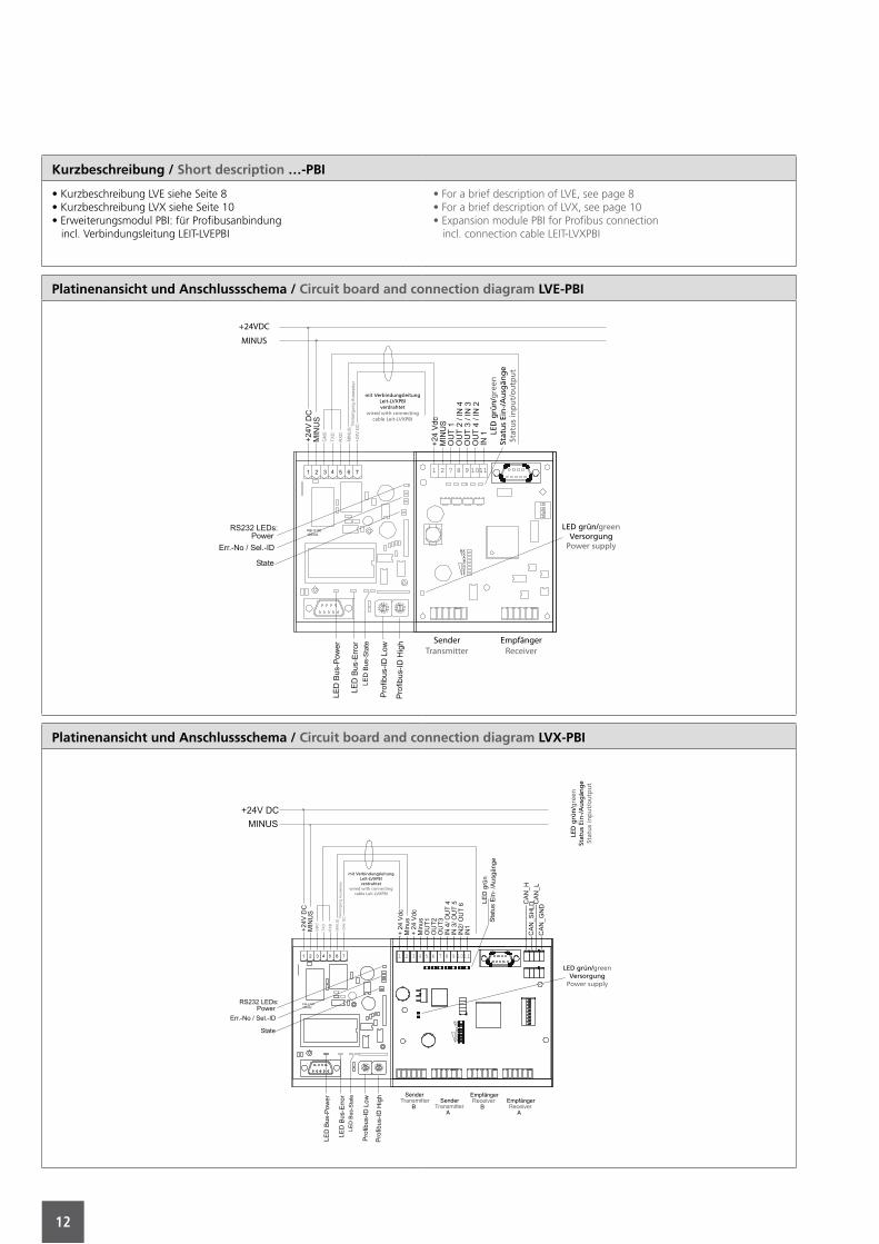
Kurzbeschreibung / Short description …-PBI
• Kurzbeschreibung LVE siehe Seite 8• Kurzbeschreibung LVX siehe Seite 10• Erweiterungsmodul PBI: für Profibusanbindung incl. Verbindungsleitung LEIT-LVEPBI
• For a brief description of LVE, see page 8• For a brief description of LVX, see page 10• Expansion module PBI for Profibus connection incl. connection cable LEIT-LVXPBI
Platinenansicht und Anschlussschema / Circuit board and connection diagram LVE-PBI
SenderTransmitter
EmpfängerReceiver
+24VDC
MINUS
mit VerbindungsleitungLeit-LVXPBIverdrahtet
wired with connecting cable Leit-LVXPBI
LED
grü
n/g
reen
Stat
us
Ein
-/A
usg
äng
eSt
atu
s in
pu
t/o
utp
ut
LED grün/greenVersorgung
Power supply
Platinenansicht und Anschlussschema / Circuit board and connection diagram LVX-PBI
SenderTransmitter
BSender
TransmitterA
EmpfängerReceiver
BEmpfängerReceiver
A
mit VerbindungsleitungLeit-LVXPBIverdrahtet
wired with connecting cable Leit-LVXPBI
LED
grü
n/g
reen
Stat
us
Ein
-/A
usg
äng
eSt
atu
s in
pu
t/o
utp
ut
LED grün/greenVersorgung
Power supply
13
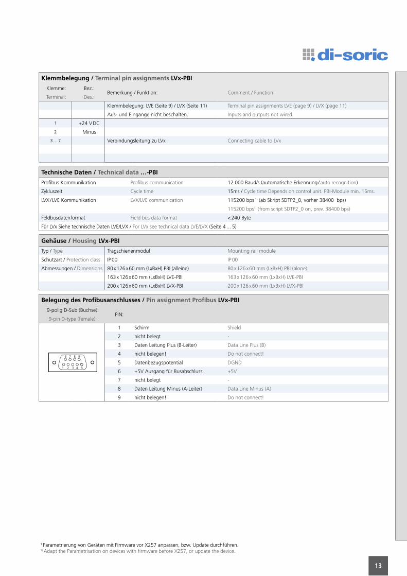
Klemmbelegung / Terminal pin assignments LVx-PBI
Klemme: Bez.:Bemerkung / Funktion: Comment / Function:
Terminal: Des.:
Klemmbelegung: LVE (Seite 9) / LVX (Seite 11) Terminal pin assignments LVE (page 9) / LVX (page 11)
Aus- und Eingänge nicht beschalten. Inputs and outputs not wired.
1 +24 V DC
2 Minus
3 … 7 Verbindungsleitung zu LVx Connecting cable to LVx
Technische Daten / Technical data …-PBI
Profibus Kommunikation Profibus communication 12.000 Baud/s (automatische Erkennung / auto recognition)
Zykluszeit Cycle time 15ms / Cycle time Depends on control unit. PBI-Module min. 15ms.
LVX / LVE Kommunikation LVX/LVE communication 115200 bps 1) (ab Skript SDTP2_0, vorher 38400 bps)
115200 bps1) (from script SDTP2_0 on, prev. 38400 bps)
Feldbusdatenformat Field bus data format < 240 Byte
Für LVx Siehe technische Daten LVE/LVX / For LVx see technical data LVE/LVX (Seite 4 … 5)
Gehäuse / Housing LVx-PBI
Typ / Type Tragschienenmodul Mounting rail module
Schutzart / Protection class IP 00 IP 00
Abmessungen / Dimensions 80 x 126 x 60 mm (LxBxH) PBI (alleine) 80 x 126 x 60 mm (LxBxH) PBI (alone)
163 x 126 x 60 mm (LxBxH) LVE-PBI 163 x 126 x 60 mm (LxBxH) LVE-PBI
200 x 126 x 60 mm (LxBxH) LVX-PBI 200 x 126 x 60 mm (LxBxH) LVX-PBI
Belegung des Profibusanschlusses / Pin assignment Profibus LVx-PBI
9-polig D-Sub (Buchse):PIN:
9-pin D-type (female):
1 3 4 52
76 8 9
1 Schirm Shield
2 nicht belegt -
3 Daten Leitung Plus (B-Leiter) Data Line Plus (B)
4 nicht belegen! Do not connect!
5 Datenbezugspotential DGND
6 +5V Ausgang für Busabschluss +5V
7 nicht belegt -
8 Daten Leitung Minus (A-Leiter) Data Line Minus (A)
9 nicht belegen! Do not connect!
1 Parametrierung von Geräten mit Firmware vor X257 anpassen, bzw. Update durchführen.1) Adapt the Parametrisation on devices with firmware before X257, or update the device.
14
Inbetriebnahme mit PBI-Modul / Start-up … with PBI-Module
LVx-PBI an Ihrer Steuerung einrichten:• Vergeben Sie eine Profibus-ID für unser Auswertegerät.• Weisen Sie Ihrer Steuerung die richtige Länge des Ausgabestrings unseres Auswertegerätes zu.• Teilen Sie den Ausgabestring auf Ihre entsprechenden Variablen auf.
Profibus-ID einstellen:• Lesen Sie die unserem Auswertegerät zugeordnete Profibus-ID aus der Steuerung aus.• Stellen Sie die BUS-ID an den beiden Drehschaltern, unten rechts am Erweiterungsmodul PBI, ein.
Auswertegerät anschließen:• Sender- und Empfängerleisten anstecken.• Profibusleitung am PBI-Modul links unten einstecken.• Auswertegerät mit der Spannungsversorgung verbinden.• PBI-Modul mit der Spannungsversorgung verbinden.
Selbstabgleich ausführen (siehe Inbetriebnahme LVX / LVE):• DIP3 auf ON.• Betriebsspannung anklemmen.• DIP3 auf OFF.
Inbetriebnahme überprüfen:• Am Erweiterungsmodul leuchten nur grüne LEDs?• Messdaten stehen in der Steuerung zur Verfügung?• Schaltfunktion ist im gesamten Überwachungsbereich gegeben?
Set up LVx-PBI at the machine control unit:• Allot the Profibus-ID to the LVX-PBI.• Allot the correct numbers of bytes for the LVX data string to the machine control unit.• Divide the data string to the corresponding variables of your program.
Set up the Profibus-ID:• Readout from the machine control unit the allocated Profibus-ID for the LVX-PBI.• Position both rotary switches, in the lower right corner of the PBI-Module, to the Profibus-ID.
Connect the control unit:• Connect the transmitter and receiver bar to the LVX-PBI.• Connect the Profibusline at the lower left side of the PBI-Module.• Connect the LVX to the supply voltage.• Connect the PBI-Module to the supply voltage.
Execute the self calibration (see start up LVX / LVE):• Switch DIP3 to “on”• Connect the supply voltage• Switch DIP3 back to “off”
Verify the correct startup:• Only green LEDs illuminate at the PBI-Module?• The measuring data is available at the machine control unit?• The interruption of a single beam is detected over the whole monitoring area?
Hinweise / Notes
• Die Profibus-ID muss vor dem Einschalten der Spannungsversorgung eingestellt werden, da diese nur dann im PBI-Modul gespeichert wird.• High- und Low-Byte der BUS-ID werden als Hexadezimalwert eingestellt.• Einstellung eines zu kurzen Ausgabestrings schneidet Daten unerkannt ab.• Für den Datenaustausch wird Profibus-DP verwendet.
• The Profibus-ID has to be set before power up, because then only the value is stored to the PBI-Module.• High- and Low-Byte of the Profibus-ID are set as hexadecimal values.• Set up of a too short data string will cut off the data unrecognised.• For data exchange the protocol Profibus-DP is used.
LEDs / LEDs
ERR. STATE LEDsZeigt ein Kommunikationsproblem zwischen Profibus und PBI-Modul an.Prüfen Sie die Einstellung der BUS-ID und die Verbindung zum Profibus.
STATE-LED oben rechtsZeigt ein Kommunikationsproblem zwischen PBI-Modul und LVX/LVE an.Prüfen Sie die Verbindungsleitung zum LVX/LVE. Führen Sie den Selbstab-gleich durch.
ERR. STATE LEDsShows a communication problem between Profibus and PBI-Module.Check the settings of the BUS-ID and the connection to the Profibus.
STATE-LED upper right cornerShows a communication problem between PBI-Module and LVX/LVE.Check the connecting cable between PBI-Module and LVX/LVE. Carry out the self calibration.
15
Notizen / Notes
16
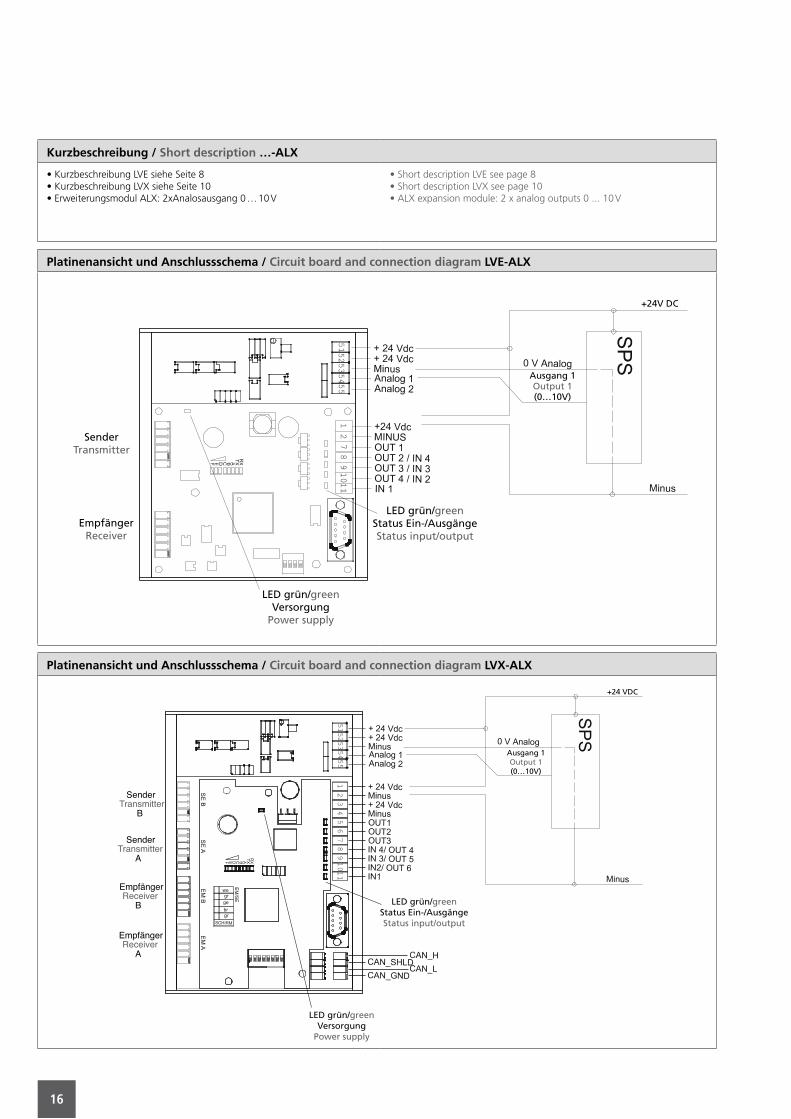
Kurzbeschreibung / Short description …-ALX
• Kurzbeschreibung LVE siehe Seite 8• Kurzbeschreibung LVX siehe Seite 10• Erweiterungsmodul ALX: 2xAnalosausgang 0 … 10 V
• Short description LVE see page 8• Short description LVX see page 10• ALX expansion module: 2 x analog outputs 0 ... 10 V
Platinenansicht und Anschlussschema / Circuit board and connection diagram LVE-ALX
SenderTransmitter
EmpfängerReceiver
LED grün/greenStatus Ein-/AusgängeStatus input/output
LED grün/greenVersorgung
Power supply
Ausgang 1Output 1(0…10V)
+24V DC
Platinenansicht und Anschlussschema / Circuit board and connection diagram LVX-ALX
SenderTransmitter
B
SenderTransmitter
A
EmpfängerReceiver
B
EmpfängerReceiver
A
LED grün/greenStatus Ein-/AusgängeStatus input/output
LED grün/greenVersorgung
Power supply
Ausgang 1Output 1(0…10V)
+24 VDC
17
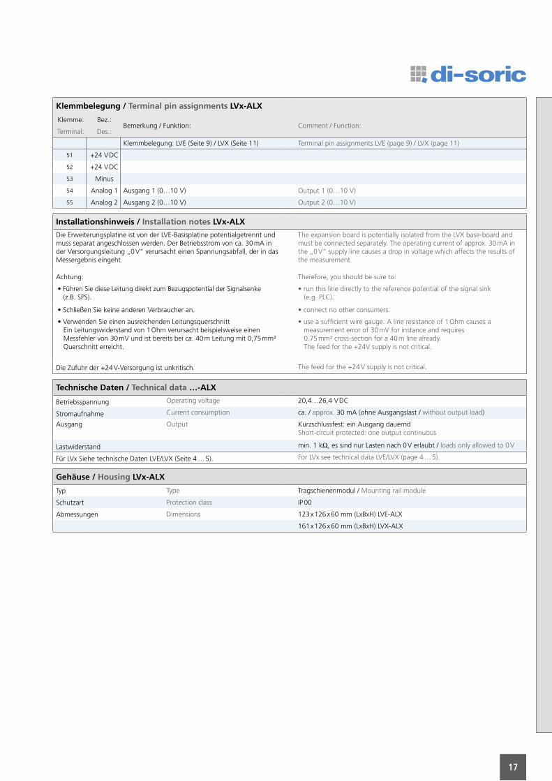
Klemmbelegung / Terminal pin assignments LVx-ALX
Klemme: Bez.:Bemerkung / Funktion: Comment / Function:
Terminal: Des.:
Klemmbelegung: LVE (Seite 9) / LVX (Seite 11) Terminal pin assignments LVE (page 9) / LVX (page 11)
51 +24 V DC
52 +24 V DC
53 Minus
54 Analog 1 Ausgang 1 (0…10 V) Output 1 (0…10 V)
55 Analog 2 Ausgang 2 (0…10 V) Output 2 (0…10 V)
Installationshinweis / Installation notes LVx-ALX
Die Erweiterungsplatine ist von der LVE-Basisplatine potentialgetrennt und muss separat angeschlossen werden. Der Betriebsstrom von ca. 30 mA in der Versorgungsleitung „0 V“ verursacht einen Spannungsabfall, der in das Messergebnis eingeht.
The expansion board is potentially isolated from the LVX base-board and must be connected separately. The operating current of approx. 30 mA in the „0 V“ supply line causes a drop in voltage which affects the results of the measurement.
Achtung: Therefore, you should be sure to:
• Führen Sie diese Leitung direkt zum Bezugspotential der Signalsenke (z.B. SPS).
• run this line directly to the reference potential of the signal sink (e.g. PLC).
• Schließen Sie keine anderen Verbraucher an. • connect no other consumers.
• Verwenden Sie einen ausreichenden Leitungsquerschnitt Ein Leitungswiderstand von 1 Ohm verursacht beispielsweise einen Messfehler von 30 mV und ist bereits bei ca. 40 m Leitung mit 0,75 mm² Querschnitt erreicht.
• use a sufficient wire gauge. A line resistance of 1 Ohm causes a measurement error of 30 mV for instance and requires 0.75 mm² cross-section for a 40 m line already. The feed for the +24V supply is not critical.
Die Zufuhr der +24 V-Versorgung ist unkritisch. The feed for the +24 V supply is not critical.
Technische Daten / Technical data …-ALX
Betriebsspannung Operating voltage 20,4…26,4 V DC
Stromaufnahme Current consumption ca. / approx. 30 mA (ohne Ausgangslast / without output load)
Ausgang Output Kurzschlussfest: ein Ausgang dauerndShort-circuit protected: one output continuous
Lastwiderstand min. 1 kΩ, es sind nur Lasten nach 0 V erlaubt / loads only allowed to 0 V
Für LVx Siehe technische Daten LVE/LVX (Seite 4 … 5). For LVx see technical data LVE/LVX (page 4 … 5).
Gehäuse / Housing LVx-ALX
Typ Type Tragschienenmodul / Mounting rail module
Schutzart Protection class IP 00
Abmessungen Dimensions 123 x 126 x 60 mm (LxBxH) LVE-ALX
161 x 126 x 60 mm (LxBxH) LVX-ALX
18
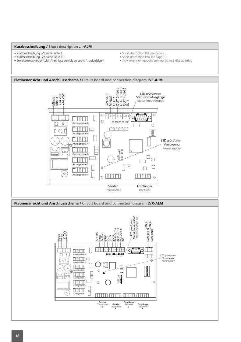
Kurzbeschreibung / Short description …-ALM
• Kurzbeschreibung LVE siehe Seite 8• Kurzbeschreibung LVX siehe Seite 10• Erweiterungsmodul ALM: Anschluss von bis zu sechs Anzeigeleisten
• Short description LVE see page 8• Short description LVX see page 10• ALM extension module: connect up to 6 display strips
Platinenansicht und Anschlussschema / Circuit board and connection diagram LVE-ALM
SenderTransmitter
EmpfängerReceiver
LED grün/greenVersorgung
Power supply
LED grün/greenStatus Ein-/AusgängeStatus input/output
+24
VD
C+
24 V
DC
+24
VD
C
Platinenansicht und Anschlussschema / Circuit board and connection diagram LVX-ALM
SenderTransmitter
BSender
TransmitterA
EmpfängerReceiver
BEmpfängerReceiver
A
LED grün/greenVersorgung
Power supply
LED
grü
n/g
reen
Stat
us
Ein
-/A
usg
äng
eSt
atu
s in
pu
t/o
utp
ut
+24
VD
C
+24
VD
C
+24
VD
C
19
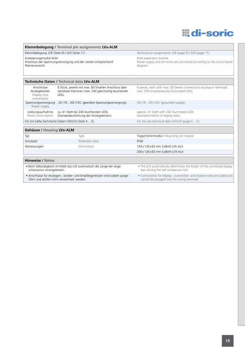
Klemmbelegung / Terminal pin assignments LVx-ALM
Klemmbelegung: LVE (Seite 9) / LVX (Seite 11) Terminal pin assignments: LVE (page 9) / LVX (page 11)
Erweiterungsmodul ALM:Anschluss der Spannungsversorgung und der Leisten entsprechendPlatinenansicht.
ALM expansion module:Power supply and terminals are connected according to the circuit board diagram.
Technische Daten / Technical data LVx-ALM
AnschlüsseAnzeigeleistenDisplay stripconnections
6 Stück, jeweils mit max. 60 Strahlen Anschluss über steckbare Klemmen max. 240 gleichzeitig leuchtende LEDs.
6 pieces, each with max. 60 beams connections via plug-in terminalsmax. 250 simultaneously illuminated LEDs.
SpannungsversorgungPower supply
24 (19…30) V DC (geerdete Spannungsversorgung). 24 (19…30) V DC (grounded supply).
LeistungsaufnahmePower consumption
ca. 41 Watt bei 240 leuchtenden LEDs(Standardausführung der Anzeigeleisten).
approx. 41 Watt with 240 illuminated LEDs(standard edition of display bars).
Für LVx Siehe technische Daten LVE/LVX (Seite 4 … 5). For LVx see technical data LVE/LVX (page 4 … 5).
Gehäuse / Housing LVx-ALM
Typ Type Tragschienenmodul / Mounting rail module
Schutzart Protection class IP 00
Abmessungen Dimensions 163 x 126 x 60 mm (LxBxH) LVE-ALX
200 x 126 x 60 mm (LxBxH) LVX-ALX
Hinweise / Notes
• Beim Selbstabgleich ermittelt das LVE automatisch die Länge der ange- schlossenen Anzeigeleisten.
• The LVX automatically determines the length of the connected display bars during the self comparison test.
• Anschlüsse für Anzeigen-, Sender- und Empfängerleisten sind codiert ausge- führt und dürfen nicht verwechselt werden.
• Connections for display-, transmitter- and receiver-rods are coded and cannot be plugged into the wrong terminal.
20
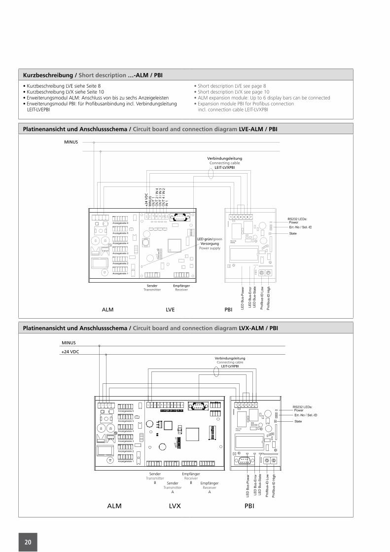
Kurzbeschreibung / Short description …-ALM / PBI
• Kurzbeschreibung LVE siehe Seite 8• Kurzbeschreibung LVX siehe Seite 10• Erweiterungsmodul ALM: Anschluss von bis zu sechs Anzeigeleisten• Erweiterungsmodul PBI: für Profibusanbindung incl. Verbindungsleitung LEIT-LVEPBI
• Short description LVE see page 8• Short description LVX see page 10• ALM expansion module: Up to 6 display bars can be connected• Expansion module PBI for Profibus connection incl. connection cable LEIT-LVXPBI
Platinenansicht und Anschlussschema / Circuit board and connection diagram LVE-ALM / PBI
ALM LVE PBI
MINUS
VerbindungsleitungConnecting cable
LEIT-LVXPBI
SenderTransmitter
EmpfängerReceiver
LED grün/greenVersorgung
Power supply
+24
VD
C
Platinenansicht und Anschlussschema / Circuit board and connection diagram LVX-ALM / PBI
SenderTransmitter
B SenderTransmitter
A
EmpfängerReceiver
B EmpfängerReceiver
A
ALM LVX PBI
MINUS
VerbindungsleitungConnecting cable
LEIT-LVXPBI
+24 VDC

21
Notizen / Notes
22
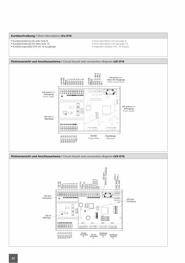
Kurzbeschreibung / Short description LVx-O16
• Kurzbeschreibung LVE siehe Seite 8• Kurzbeschreibung LVX siehe Seite 10• Erweiterungsmodul O16 mit 16 Ausgängen
• Short description LVE see page 8• Short description LVX see page 10• Expansion module O16: 16 outputs
Platinenansicht und Anschlussschema / Circuit board and connection diagram LVE-O16M
inus
2221 23 31 32 33 34 35 36 37 38
OU
T1
OU
T2
OU
T3
OU
T4
OU
T5
OU
T6
OU
T7
OU
T8
48
OU
T16
47
OU
T15
46
OU
T14
45
OU
T13
44
OU
T12
43
OU
T11
42
OU
T10
41
OU
T9 Empfänger
ReceiverSender
Transmitter
OU
T4
/ IN
2O
UT
3/ I
N3
OU
T2
/ IN
4O
UT
1M
INU
S
IN1
C
FED
BA
TXRX
1 2 7 8 9 10 11
LED grün/greenStatus Ein-/AusgängeStatus input/output
+24
VD
C+
24 V
DC
+24
VD
C
LED grün/greenVersorgung
Power supply
LED rot/redWatchdog
LED grün/greenVersorgung
Power supply
Platinenansicht und Anschlussschema / Circuit board and connection diagram LVX-O16
SenderTransmitter
BSender
TransmitterA
EmpfängerReceiver
BEmpfängerReceiver
A
23
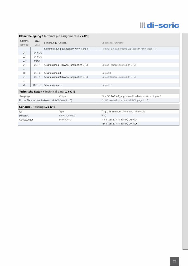
Klemmbelegung / Terminal pin assignments LVx-O16
Klemme: Bez.:Bemerkung / Funktion: Comment / Function:
Terminal: Des.:
Klemmbelegung: LVE (Seite 9) / LVX (Seite 11) Terminal pin assignments LVE (page 9) / LVX (page 11)
21 +24 V DC
22 +24 V DC
23 Minus
31 OUT 1 Schaltausgang 1 (Erweiterungsplatine O16) Output 1 (extension module O16)
…
38 OUT 8 Schaltausgang 8 Output 8
41 OUT 9 Schaltausgang 9 (Erweiterungsplatine O16) Output 9 (extension module O16)
…
48 OUT 16 Schaltausgang 16 Output 16
Technische Daten / Technical data LVx-O16
Ausgänge Outputs 24 V DC, 200 mA, pnp, kurzschlussfest / short circuit proof
Für LVx Siehe technische Daten LVE/LVX (Seite 4 … 5) For LVx see technical data LVE/LVX (page 4 … 5)
Gehäuse /Housing LVx-O16
Typ Type Tragschienenmodul / Mounting rail module
Schutzart Protection class IP 00
Abmessungen Dimensions 148 x 126 x 60 mm (LxBxH) LVE-ALX
184 x 126 x 60 mm (LxBxH) LVX-ALX
24
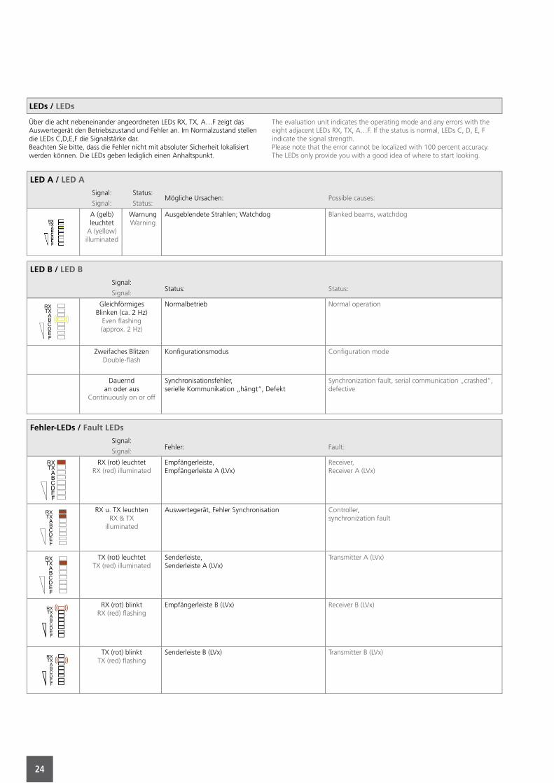
LEDs / LEDs
Über die acht nebeneinander angeordneten LEDs RX, TX, A…F zeigt das Auswertegerät den Betriebszustand und Fehler an. Im Normalzustand stellen die LEDs C,D,E,F die Signalstärke dar.Beachten Sie bitte, dass die Fehler nicht mit absoluter Sicherheit lokalisiert werden können. Die LEDs geben lediglich einen Anhaltspunkt.
The evaluation unit indicates the operating mode and any errors with the eight adjacent LEDs RX, TX, A…F. If the status is normal, LEDs C, D, E, F indicate the signal strength.Please note that the error cannot be localized with 100 percent accuracy.The LEDs only provide you with a good idea of where to start looking.
LED A / LED A
Signal: Status:Mögliche Ursachen: Possible causes:
Signal: Status:
A (gelb) leuchtet
A (yellow) illuminated
Warnung Warning
Ausgeblendete Strahlen; Watchdog Blanked beams, watchdog
LED B / LED B
Signal:Status: Status:
Signal:
GleichförmigesBlinken (ca. 2 Hz)
Even fl ashing(approx. 2 Hz)
Normalbetrieb Normal operation
Zweifaches BlitzenDouble-fl ash
Konfi gurationsmodus Confi guration mode
Dauerndan oder aus
Continuously on or off
Synchronisationsfehler,serielle Kommunikation „hängt“, Defekt
Synchronization fault, serial communication „crashed“, defective
Fehler-LEDs / Fault LEDs
Signal:Fehler: Fault:
Signal:
RX (rot) leuchtetRX (red) illuminated
Empfängerleiste,Empfängerleiste A (LVx)
Receiver,Receiver A (LVx)
RX u. TX leuchtenRX & TX
illuminated
Auswertegerät, Fehler Synchronisation Controller,synchronization fault
TX (rot) leuchtetTX (red) illuminated
Senderleiste,Senderleiste A (LVx)
Transmitter A (LVx)
RX (rot) blinktRX (red) fl ashing
Empfängerleiste B (LVx) Receiver B (LVx)
TX (rot) blinktTX (red) fl ashing
Senderleiste B (LVx) Transmitter B (LVx)
25
Anschluss der Lichtgitterleisten / Connecting the rods
• Betriebsspannung abklemmen• Anschlüsse nicht vertauschen!• Die Lichtgitterleisten können durch vertauschte Adern beschädigt werden!• Kodierung der Steckerteile beachten: Steckerteile passen nur in die zugehörigen Buchsen
• Disconnect power supply• Do not switch connections!• The light screen rods can be damaged if poles are switched!• Note the plug coding. Plug components will only plug into the corresponding sockets
Standard
M12, 5-polig / poled
M12-Steckergehäuse und Leistengehäuse haben das gleiche Potential. / The M12 plug housing and the strip housing have the same potential.Das M12-Steckergehäuse ist mit 0 V verbunden und muss isoliert werden / The M12-connector housing is connected to 0 V and has to be isolated.
Besondere LED-Kombinationen / Special LED combinations
Hardwarefehler, bitte Hersteller informieren. Hardware fault, please inform manufacturer.
Länge der angeschlossenen Leisten entspricht nicht den gespeicherten Werten => Selbstabgleich durchführen!
Length of connected rods does not correspond with stored values => perform self-comparison (self-test)
Hardwarefehler, bitte Hersteller informieren. Hardware fault, please inform manufacturer.
Parameter außerhalb der zulässigen Grenzwerte => im Konfigurationsmodus korrigieren (ggf. zurücksetzen auf Voreinstellung).
Parameter outside of permitted limit values => correct in configuration mode (reset to defaults if necessary).

26
Notizen / Notes

27
Notizen / Notes

© di-soric www.di-soric.comwww.di-soric.de
Produktprogramm
LightingPhotoelectric sensorsContrast diffuse sensorsDistance sensorsColour and surface sensorsFibre-optic cables / - amplifi ersLight curtainsSafety light curtainsAngled light barriersFork light barriers Ring light barriersFrame light barriers Ring and tube sensorsProximity switchesLabel sensorsCylinder sensorsContact sensorsUltrasonic sensorsMovement sensorsInclination sensors
Accessories
Product program
BeleuchtungenLichtschrankenKontrasttasterAbstandssensorenFarb- und Oberfl ächensensorenLichtleitkabel / - VerstärkerLichtgitterSicherheitslichtgitter WinkellichtschrankenGabellichtschrankenRinglichtschrankenRahmenlichtschrankenRing- und SchlauchsensorenNäherungsschalterEtikettensensorenZylindersensorenKontaktsensorenUltraschallsensorenBewegungssensorenNeigungssensorenKamerasensorenZubehör
Europa AsienAustralienNordamerika Südamerika Afrika
EuropeAsiaAustraliaNorth America South America Africa
di-soric GmbH & Co. KG Steinbeisstraße 6DE-73660 UrbachFon: +49 (0) 71 81 / 98 79 - 0Fax: +49 (0) 71 81 / 98 79 - 179E-Mail: [email protected]: www.di-soric.de