Embed Size (px)
Citation preview

August 2016 / Bulletin 100-50-5.1
Superheat ControlInstallation and Operation Instructions
Controller v. J
Page 2 – Bulletin 100-50-5.1
1. Installation . . . . . . . . . . . . . . . . . . . . . . . . . . . . . . 3
2. Setup. . . . . . . . . . . . . . . . . . . . . . . . . . . . . . . . . . 4 Superheat Control with Display . . . . . . . . . . . . . . 4 Superheat Control without Display . . . . . . . . . . . . 5
3. Setpoint Menu Operation . . . . . . . . . . . . . . . . . . . 5
4. System Operation . . . . . . . . . . . . . . . . . . . . . . . . 5 Refrigeration . . . . . . . . . . . . . . . . . . . . . . . . . . . . 5 Chillers and Air Conditioners . . . . . . . . . . . . . . . . 5 Control Features . . . . . . . . . . . . . . . . . . . . . . . . . 6 System Parameters . . . . . . . . . . . . . . . . . . . . . . . 6
5. Display Networking . . . . . . . . . . . . . . . . . . . . . . . 9 Multiple Controllers . . . . . . . . . . . . . . . . . . . . . . . 9 Junction Box Fabrication . . . . . . . . . . . . . . . . . . . 9
6. Controller Networking . . . . . . . . . . . . . . . . . . . . 10 Scaling. . . . . . . . . . . . . . . . . . . . . . . . . . . . . . . . 10 Setup. . . . . . . . . . . . . . . . . . . . . . . . . . . . . . . . . 10 MODBUS Connection Requirements . . . . . . . . . 10
7. PID Tuning . . . . . . . . . . . . . . . . . . . . . . . . . . . . . 11
8. Troubleshooting . . . . . . . . . . . . . . . . . . . . . . . . . 11 Troubleshooting Recommendations . . . . . . . . . . 11 Sensors . . . . . . . . . . . . . . . . . . . . . . . . . . . . . . . 13 Alarms . . . . . . . . . . . . . . . . . . . . . . . . . . . . . . . . 13
APPENDIX A Setup Menu . . . . . . . . . . . . . . . . . . . . . . . . . . . . 14
APPENDIX B Process Values . . . . . . . . . . . . . . . . . . . . . . . . . 15
APPENDIX C Setpoint Parameters . . . . . . . . . . . . . . . . . . . 16-17
APPENDIX D Accessories . . . . . . . . . . . . . . . . . . . . . . . . . . . . 18
APPENDIX E Technical Specifications . . . . . . . . . . . . . . . . . . . 18
APPENDIX F Controller Status . . . . . . . . . . . . . . . . . . . . . . . . 18
APPENDIX G Miscellaneous Displays . . . . . . . . . . . . . . . . . . . 18
APPENDIX H Wiring Diagram . . . . . . . . . . . . . . . . . . . . . . . . . 19
APPENDIX I Sensor Installation . . . . . . . . . . . . . . . . . . . . . . . 20
APPENDIX J MODBUS Memory Map . . . . . . . . . . . . . . . . . 21-22
APPENDIX K BACnet Map . . . . . . . . . . . . . . . . . . . . . . . . . 23-30
APPENDIX L 2K Temperature Sensor Specifications. . . . . . . . 31
APPENDIX M 3K Temperature Sensor Specifications. . . . . . . . 32
Terms of Sale with Warranty Limitations. . . . . . . . . 33
Contents
⚠WARNING – USER RESPONSIBILITYFailure or improper selection or improper use of the products described herein or related items can cause death, personal injury and property damage.
This document and other information from Parker Hannifin Corporation, its subsidiaries and authorized distributors provide product or system options for further investigation by users having technical expertise.
The user, through its own analysis and testing, is solely responsible for making the final selection of the system and components and assuring that all performance, endurance, maintenance, safety and warning requirements of the application are met. The user must analyze all aspects of the application, follow applicable industry standards, and follow the information concerning the product in the current product catalog and in any other materials provided from Parker or its subsidiaries or authorized distributors.
To the extent that Parker or its subsidiaries or authorized distributors provide component or system options based upon data or specifications provided by the user, the user is responsible for determining that such data and specifications are suitable and sufficient for all applications and reasonably foreseeable uses of the components or systems.
For safety information see the Safety Guide at www.parker.com/safety or call 1-800-CParker.
OFFER OF SALEThe items described in this document are hereby offered for sale by Parker Hannifin Corporation, its subsidiaries or its authorized distributors. This offer and its acceptance are governed by the provisions stated in the detailed “Offer of Sale” available at www.parker.com.
FOR USE ON REFRIGERATION and/or AIR CONDITIONING SYSTEMS ONLY
For more information about our products visit us at www.sporlan.com.Bulletin 100-50-5.1, August 2016 supersedes Bulletin 100-50-5.1, October 2012 and all prior publications.
IntroductionThe Sporlan Superheat Control is a standalone controller for refrigeration and air conditioning sys-tems. The controller operates an electronic expan-sion valve to control superheat. It may also be used to control room temperature. The controller may be networked into a building automation system and offers several communication protocols. It is avail-able with or without display for aftermarket or OEM use. A remote display unit is optional.
Features• Superheat or room temperature control
• 4-digit LED display with easy to use input knob
• OEM version available without display
• Optional remote display unit
• Optional display networking between controllers
• BACnet or MODBUS communication protocols
• One bi-polar or uni-polar step motor driver (30ohm/coil minimum)
• One mechanical relay output (for liquid line sole-noid or piloting a compressor relay)
• Four temperature inputs (Sporlan surface or air sensor)
• One pressure input (Sporlan pressure transducer)
• One digital input (for external switch or relay)
Bulletin 100-50-5.1 – Page 3
1. InstallationRefer to Appendix H - Wiring Diagram and Appendix I - Sensor Installation
TOOLS REQUIRED:• Small flat screwdriver for terminal connections• Phillips and flat screwdrivers• Cordless screwdriver• Needle-nose pliers• Wire cutters• Scotch-BriteTM pad • Two #8 x ½” self-tapping screws to mount DIN rail
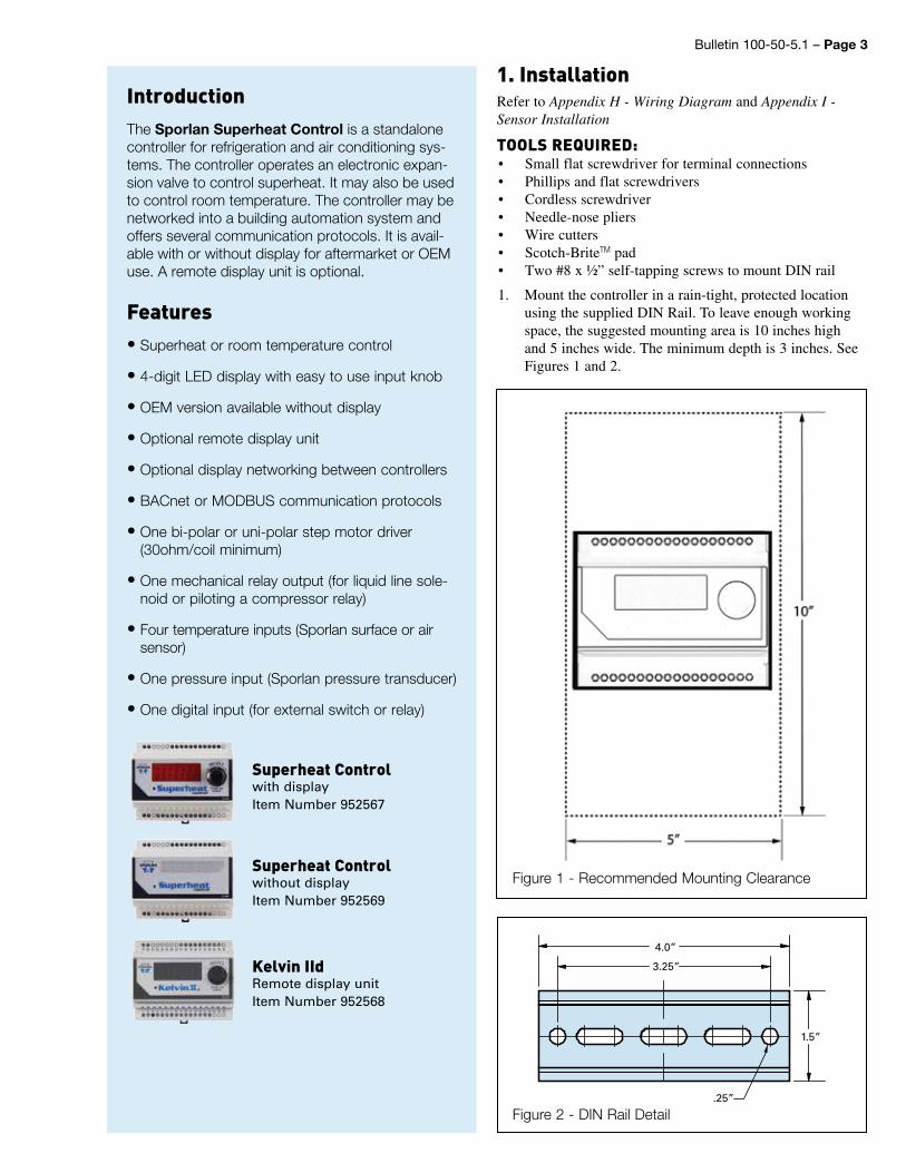
1. Mount the controller in a rain-tight, protected location using the supplied DIN Rail. To leave enough working space, the suggested mounting area is 10 inches high and 5 inches wide. The minimum depth is 3 inches. See Figures 1 and 2.
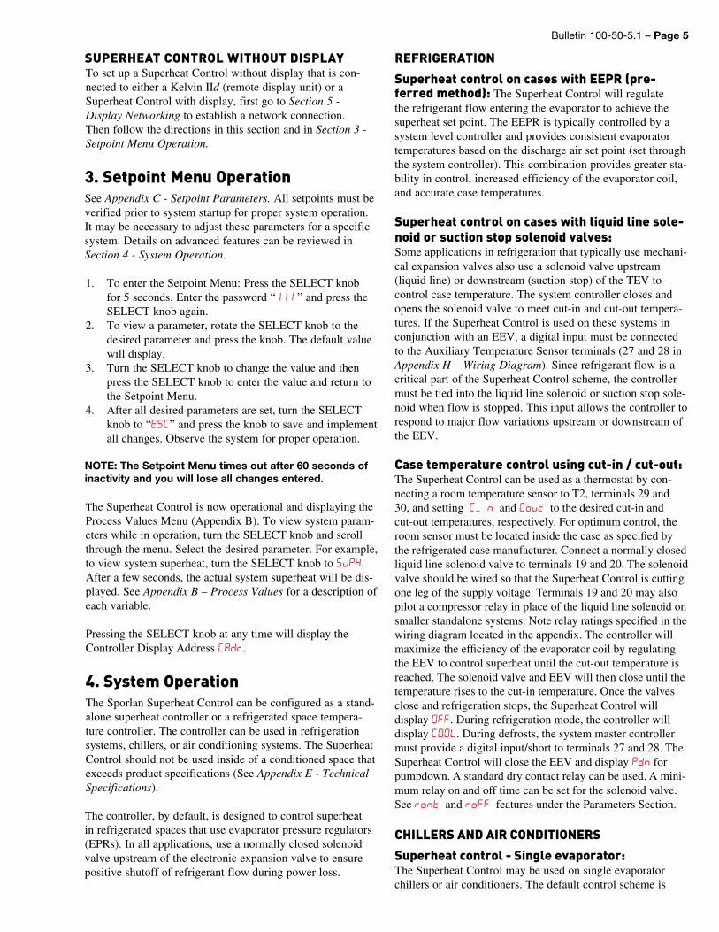
Superheat Controlwith displayItem Number 952567
Superheat Controlwithout displayItem Number 952569
Kelvin IIdRemote display unitItem Number 952568
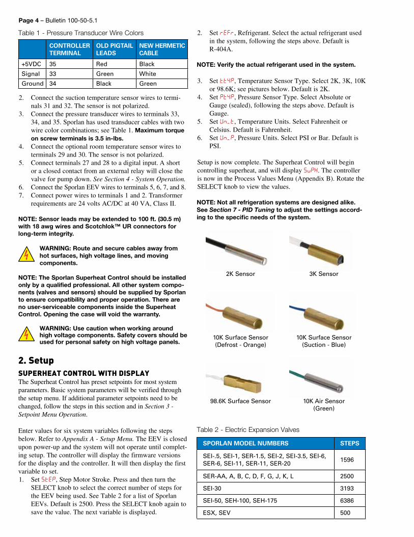
Figure 2 - DIN Rail Detail
1.5”
.25”
4.0”
3.25”
Figure 1 - Recommended Mounting Clearance
2. Connect the suction temperature sensor wires to termi-nals 31 and 32. The sensor is not polarized.
3. Connect the pressure transducer wires to terminals 33, 34, and 35. Sporlan has used transducer cables with two wire color combinations; see Table 1. Maximum torque on screw terminals is 3.5 in-lbs.
4. Connect the optional room temperature sensor wires to terminals 29 and 30. The sensor is not polarized.
5. Connect terminals 27 and 28 to a digital input. A short or a closed contact from an external relay will close the valve for pump down. See Section 4 - System Operation.
6. Connect the Sporlan EEV wires to terminals 5, 6, 7, and 8.7. Connect power wires to terminals 1 and 2. Transformer
requirements are 24 volts AC/DC at 40 VA, Class II.8. NOTE: Sensor leads may be extended to 100 ft. (30.5 m) with 18 awg wires and Scotchlok™ UR connectors for long-term integrity.
WARNING: Route and secure cables away from hot surfaces, high voltage lines, and moving components.
NOTE: The Sporlan Superheat Control should be installed only by a qualified professional. All other system compo-nents (valves and sensors) should be supplied by Sporlan to ensure compatibility and proper operation. There are no user-serviceable components inside the Superheat Control. Opening the case will void the warranty.
WARNING: Use caution when working around high voltage components. Safety covers should be used for personal safety on high voltage panels.
2. SetupSUPERHEAT CONTROL WITH DISPLAYThe Superheat Control has preset setpoints for most system parameters. Basic system parameters will be verified through the setup menu. If additional parameter setpoints need to be changed, follow the steps in this section and in Section 3 - Setpoint Menu Operation.
Enter values for six system variables following the steps below. Refer to Appendix A - Setup Menu. The EEV is closed upon power-up and the system will not operate until complet-ing setup. The controller will display the firmware versions for the display and the controller. It will then display the first variable to set.1. Set StEP, Step Motor Stroke. Press and then turn the
SELECT knob to select the correct number of steps for the EEV being used. See Table 2 for a list of Sporlan EEVs. Default is 2500. Press the SELECT knob again to save the value. The next variable is displayed.
CONTROLLER TERMINAL
OLD PIGTAIL LEADS
NEW HERMETIC CABLE
+5VDC 35 Red Black
Signal 33 Green White
Ground 34 Black Green
Table 1 - Pressure Transducer Wire Colors
Page 4 – Bulletin 100-50-5.1
2. Set reFr, Refrigerant. Select the actual refrigerant used in the system, following the steps above. Default is R-404A.
NOTE: Verify the actual refrigerant used in the system.
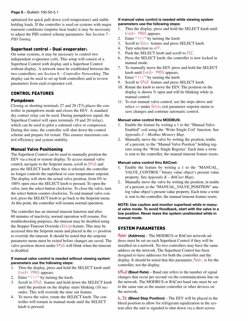
3. Set tt4P, Temperature Sensor Type. Select 2K, 3K, 10K or 98.6K; see pictures below. Default is 2K.
4. Set Pt4P, Pressure Sensor Type. Select Absolute or Gauge (sealed), following the steps above. Default is Gauge.
5. Set Un_t, Temperature Units. Select Fahrenheit or Celsius. Default is Fahrenheit.
6. Set Un_p, Pressure Units. Select PSI or Bar. Default is PSI.
Setup is now complete. The Superheat Control will begin controlling superheat, and will display SvpH. The controller is now in the Process Values Menu (Appendix B). Rotate the SELECT knob to view the values.
NOTE: Not all refrigeration systems are designed alike. See Section 7 - PID Tuning to adjust the settings accord-ing to the specific needs of the system.
3K Sensor2K Sensor
10K Surface Sensor (Suction - Blue)
10K Surface Sensor(Defrost - Orange)
10K Air Sensor (Green)
98.6K Surface Sensor
Table 2 - Electric Expansion Valves
SPORLAN MODEL NUMBERS STEPS
SEI-.5, SEI-1, SER-1.5, SEI-2, SEI-3.5, SEI-6,SER-6, SEI-11, SER-11, SER-20
1596
SER-AA, A, B, C, D, F, G, J, K, L 2500
SEI-30 3193
SEI-50, SEH-100, SEH-175 6386
ESX, SEV 500
Bulletin 100-50-5.1 – Page 5
SUPERHEAT CONTROL WITHOUT DISPLAYTo set up a Superheat Control without display that is con-nected to either a Kelvin IId (remote display unit) or a Superheat Control with display, first go to Section 5 - Display Networking to establish a network connection. Then follow the directions in this section and in Section 3 - Setpoint Menu Operation.
3. Setpoint Menu OperationSee Appendix C - Setpoint Parameters. All setpoints must be verified prior to system startup for proper system operation. It may be necessary to adjust these parameters for a specific system. Details on advanced features can be reviewed in Section 4 - System Operation.
1. To enter the Setpoint Menu: Press the SELECT knob for 5 seconds. Enter the password “111 ” and press the SELECT knob again.
2. To view a parameter, rotate the SELECT knob to the desired parameter and press the knob. The default value will display.
3. Turn the SELECT knob to change the value and then press the SELECT knob to enter the value and return to the Setpoint Menu.
4. After all desired parameters are set, turn the SELECT knob to “ESC” and press the knob to save and implement all changes. Observe the system for proper operation.
NOTE: The Setpoint Menu times out after 60 seconds of inactivity and you will lose all changes entered.
The Superheat Control is now operational and displaying the Process Values Menu (Appendix B). To view system param-eters while in operation, turn the SELECT knob and scroll through the menu. Select the desired parameter. For example, to view system superheat, turn the SELECT knob to SvPH. After a few seconds, the actual system superheat will be dis-played. See Appendix B – Process Values for a description of each variable.
Pressing the SELECT knob at any time will display the Controller Display Address CAdr.
4. System OperationThe Sporlan Superheat Control can be configured as a stand-alone superheat controller or a refrigerated space tempera-ture controller. The controller can be used in refrigeration systems, chillers, or air conditioning systems. The Superheat Control should not be used inside of a conditioned space that exceeds product specifications (See Appendix E - Technical Specifications).
The controller, by default, is designed to control superheat in refrigerated spaces that use evaporator pressure regulators (EPRs). In all applications, use a normally closed solenoid valve upstream of the electronic expansion valve to ensure positive shutoff of refrigerant flow during power loss.
REFRIGERATION
Superheat control on cases with EEPR (pre-ferred method): The Superheat Control will regulate the refrigerant flow entering the evaporator to achieve the superheat set point. The EEPR is typically controlled by a system level controller and provides consistent evaporator temperatures based on the discharge air set point (set through the system controller). This combination provides greater sta-bility in control, increased efficiency of the evaporator coil, and accurate case temperatures.
Superheat control on cases with liquid line sole-noid or suction stop solenoid valves:Some applications in refrigeration that typically use mechani-cal expansion valves also use a solenoid valve upstream (liquid line) or downstream (suction stop) of the TEV to control case temperature. The system controller closes and opens the solenoid valve to meet cut-in and cut-out tempera-tures. If the Superheat Control is used on these systems in conjunction with an EEV, a digital input must be connected to the Auxiliary Temperature Sensor terminals (27 and 28 in Appendix H – Wiring Diagram). Since refrigerant flow is a critical part of the Superheat Control scheme, the controller must be tied into the liquid line solenoid or suction stop sole-noid when flow is stopped. This input allows the controller to respond to major flow variations upstream or downstream of the EEV.
Case temperature control using cut-in / cut-out:The Superheat Control can be used as a thermostat by con-necting a room temperature sensor to T2, terminals 29 and 30, and setting C_n and Cvt to the desired cut-in and cut-out temperatures, respectively. For optimum control, the room sensor must be located inside the case as specified by the refrigerated case manufacturer. Connect a normally closed liquid line solenoid valve to terminals 19 and 20. The solenoid valve should be wired so that the Superheat Control is cutting one leg of the supply voltage. Terminals 19 and 20 may also pilot a compressor relay in place of the liquid line solenoid on smaller standalone systems. Note relay ratings specified in the wiring diagram located in the appendix. The controller will maximize the efficiency of the evaporator coil by regulating the EEV to control superheat until the cut-out temperature is reached. The solenoid valve and EEV will then close until the temperature rises to the cut-in temperature. Once the valves close and refrigeration stops, the Superheat Control will display FF. During refrigeration mode, the controller will display C. During defrosts, the system master controller must provide a digital input/short to terminals 27 and 28. The Superheat Control will close the EEV and display pdn for pumpdown. A standard dry contact relay can be used. A mini-mum relay on and off time can be set for the solenoid valve. See rnt and rF features under the Parameters Section.
CHILLERS AND AIR CONDITIONERS
Superheat control - Single evaporator:The Superheat Control may be used on single evaporator chillers or air conditioners. The default control scheme is
Page 6 – Bulletin 100-50-5.1
optimized for quick pull down (coil temperature) and stable holding loads. If the controller is used on systems with major transient conditions (impulse heat loads) it may be necessary to adjust the PID control scheme parameters. See Section 7 - PID Tuning.
Superheat control - Dual evaporator:On some systems, it may be necessary to control two independent evaporator coils. This setup will consist of a Superheat Control with display and a Superheat Control without display. A network must be established between the two controllers; see Section 6 – Controller Networking. The display can be used to set up both controllers and to review parameters from each evaporator coil.
CONTROL FEATURES
Pumpdown Closing or shorting terminals 27 and 28 (T3) places the con-troller in pumpdown mode and closes the EEV. A standard dry contact relay can be used. During pumpdown signal, the Superheat Control will open terminals 19 and 20 (relay), which can be used to pilot a solenoid valve or compressor. During this time, the controller will shut down the control scheme and prepare for restart. This ensures maximum con-trol efficiency and system stability.
Manual Valve Positioning The Superheat Control can be used to manually position the EEV via a local or remote display. To access manual valve control, navigate to the Setpoint menu, scroll to SPS and press the SELECT knob. Once this is selected, the controller no longer controls the superheat or case temperature setpoint. The display will show the actual valve position, from 0% to 100% open once the SELECT knob is pressed. To open the valve, turn the select button clockwise. To close the valve, turn the select button counter-clockwise. To end manual valve con-trol, press the SELECT knob to go back to the Setpoint menu. At this point, the controller will resume normal operation.
The controller has an internal timeout function and after 60 minutes of inactivity, normal operation will resume. For troubleshooting purposes, the timeout may be disabled using the Stepper Timeout Override (Stt) feature. This may be accessed thru the Setpoint menu and placed in the n position to override the timeout. It should be noted that the setpoint parameter menu must be exited before changes are saved. The valve position shown under SPS will blink when the timeout is disabled.
If manual valve control is needed without viewing system parameters use the following steps:1. Thru the display, press and hold the SELECT knob until
EE PASS appears.2. Enter “111 ” by turning the knob.3. Scroll to SPS feature and hold down the SELECT knob
until the position on the display starts blinking (10 sec-onds). This will override the time out feature.
4. To move the valve, rotate the SELECT knob. The con-troller will remain in manual mode until the SELECT knob is pressed.
If manual valve control is needed while viewing system parameters use the following steps:1. Thru the display, press and hold the SELECT knob until
EE PASS appears.2. Enter “111 ” by turning the knob.3. Scroll to Stt feature and press SELECT knob.4. Turn selection to .5. Push the SELECT knob and scroll to ESC.6. Press the SELECT knob; the controller is now locked in
manual mode.7. To manually move the EEV press and hold the SELECT
knob until EE PASS appears.8. Enter “111 ” by turning the knob.9. Scroll to Sp feature and press SELECT knob.10. Rotate the knob to move the EEV. The position on the
display is shown % open and will be blinking while in manual control.
11. To exit manual valve control, use the steps above and select n under Stt; exit parameter setpoint menu to save changes and continue automatic control.
Manual valve control thru MODBUS:1. Enable the feature by writing a 1 to the “Manual Valve
Enabled” coil using the ‘Write Single Coil’ function. See Appendix J – Modbus Memory Map.
2. Manually move the valve by writing the position, tenths of a percent, to the “Manual Valve Position” holding reg-ister using the ‘Write Single Register.’ Each time a write is sent to the controller, the manual timeout feature resets.
Manual valve control thru BACnet:1. Enable the feature by writing a 1 to the “MANUAL_
VALVE_CONTROL” binary value object’s present value property. See Appendix K – BACnet Map).
2. Manually move the valve by writing the position, in tenths of a percent, to the “MANUAL_VALVE_POSITION” ana-log value object’s present value property. Each time a write is sent to the controller, the manual timeout feature resets.
NOTE: Use caution and monitor superheat while in manu-al valve mode. To avoid floodback, start with the valve in a low position. Never leave the system unattended while in manual mode.
SYSTEM PARAMETERS
Addr (Address) – The MODBUS or BACnet network ad-dress must be set on each Superheat Control if they will be installed on a network. No two controllers may have the same address on the network. The Superheat Control has been designed to have addresses for both the controller and the display. It should be noted that this parameter, Addr, is for the controller, not the display.
vd (Baud Rate) – Baud rate refers to the number of signal changes that occur per second via the communications line on the network. The MODBUS or BACnet baud rate must be set to the same rate as the master controller or other devices on the network.
_S (Bleed Step Position) – The EEV will be placed in the bleed position to allow for refrigerant equalization in the sys-tem after the unit is signaled to shut down via a short across
Bulletin 100-50-5.1 – Page 7
terminals 27 and 28. The bleed position works in conjunction with _d, bleed delay feature. The default bleed position is 0%. See below for more information.
_d (Bleed Delay) – The bleed delay feature works with the _S, bleed step position feature. Once the system gets a signal to shut down via a short across terminals 27 and 28, the EEV will close to 0% then dwell for the bleed delay time, in seconds, before moving to the bleed delay position for system pressure equalization. The default bleed delay time is 0 sec-onds. See below for more information.
Bleed System Equalization (_S, _d)Use of an EEV can dramatically improve efficiency of a re-frigeration or air conditioning system. By accurately control-ling the system’s superheat, the EEV achieves full utilization of the evaporator coil surface area. A drawback to the use of EEVs with some compressors is the need for off-cycle pressure equalization of high to low system pressure. Specifi-cally, when the system is off the compressor is not cycling refrigerant and the EEV is closed. This keeps refrigerant from flowing thru the system. This condition can cause high back-pressure on the discharge side of the compressor, and hence, a hard start condition. Setting a Bleed Step Position, _S, al-lows a small amount of liquid refrigerant to pass thru the EEV while the system is off. Normal industry practice is to set a bleed to equalize the system in 3-5 minutes. The Superheat Control also allows the delay of the bleed process by setting the Bleed Delay parameter, _d.
Cdr (Controller Display Address) – The display address must be set when viewing multiple Superheat Controls thru a single display. If a display network is not used between control-lers, the Cdr must remain at default values. No two control-lers may have the same address on the network. The Superheat Control has been designed to have addresses for both the controller and the display. It should be noted that this param-eter, Cdr, is for the display, not the controller. See ‘Display Networking’ section for more information.
C_n (Cut In Temperature) – The cut in feature may be used if case temperature control via cut in/cut out is desired. It is used with the Cut Out feature, Cvt. The Superheat Control will start the system once the case temperature rises to the cut in temperature set point. The refrigeration mode will remain on until the case temperature falls to the cut out temperature set point. To activate this feature, adjust the cut in temperature set point to the desired value. See ‘System Operation’ section for further description.
Cvt (Cut Out Temperature) – The cut out feature may be used if case temperature control via cut in/cut out is desired. It is used with the Cut In feature, C_n. The Superheat Control will stop the system once the case temperature falls to the cut out temperature set point. The refrigeration mode will remain off until the case temperature rises to the cut in temperature set point. To activate this feature, adjust the cut out temperature set point to the desired value. See ‘System Operation’ section for further description.
CAP (Calibration Pressure Sensor) – The Superheat Con-trol has adjustable calibration offsets for the pressure sensor. By default, it is set to 0. This parameter may be adjusted to compensate any error with the pressure sensor.
Ct1 (Calibration Temperature Sensor T1 Suction) – The Superheat Control has adjustable calibration offsets for the temperature sensors. By default, it is set to 0. This parameter may be adjusted to compensate any error with the temperature sensor.
Ct (Calibration Temperature Sensor T2 Room) – The Superheat Control has adjustable calibration offsets for the temperature sensors. By default, it is set to 0. This parameter may be adjusted to compensate any error with the temperature sensor.
Ct (Calibration Temperature Sensor T3) – The Superheat Control has adjustable calibration offsets for the temperature sensors. By default, it is set to 0. This parameter may be ad-justed to compensate any error with the temperature sensor.
Ct4 (Calibration Temperature Sensor T4) – The Superheat Control has adjustable calibration offsets for the temperature sensors. By default, it is set to 0. This parameter may be ad-justed to compensate any error with the temperature sensor.
d (Derivative Control Gain) – The derivative gain is part of the PID control scheme. In general the derivative gain ef-fects the speed of the electronic valve in response to the rate of change in superheat error. The derivative gain is sensitive to noise and if set too high the valve may overreact and system oscillations may occur. The derivative gain is generally set to 1 for most systems. See PID tuning section for more information.
dnd (Dead Band) – This feature provides a smoother opera-tional range around superheat setpoint. For tighter superheat control, the dead band may be decreased. The Superheat Control has +/- 2°F and +/- 1°F options.
d_n (Delay On) – This feature sets a delay time before en-ergizing terminals 19 and 20 after the EEV reaches the Delay Percent Open position set by d_St. It may be used on small single compressor systems to position the EEV prior to start-ing the system. If the Superheat Control gets a signal to start the system (remove dry contact/short across terminals 27 and 28), it moves the EEV to the Delay Percent Open position, en-ergizes the relay terminals 19 and 20 after the Delay On time has been met. Delay On time is in seconds and starts when the EEV is at the Delay Percent Open position. Terminals 19 and 20 can be used to pilot a compressor relay.
d (Delay Off) – This feature sets a delay time before de-energizing terminals 19 and 20 after the EEV reaches 0% position. If the Superheat Control gets a pumpdown signal to shut off the system (dry contact/short across terminals 27 and 28), it closes the EEV and waits for system pumpdown by the specified Delay Off time, then de-energizes the relay termi-nals 19 and 20. Delay Off time is in seconds and starts when the controller receives a pumpdown signal or enters ‘OFF’ mode. Terminals 19 and 20 can be used to pilot a compressor relay.
d_St (Delay Percent Open) – This feature is used in con-junction with delay on, d_n, and is used to help equalize system pressure prior to starting smaller, standalone systems. The EEV position will move to the percent open position for the time set by d_n.
Page 8 – Bulletin 100-50-5.1
HCP (Max Valve Capacity) – The maximum valve capacity feature can be used to limit the EEV opening. This may be used to compensate for an improper, oversized EEV. If set too low however, system superheat may become too high.
H_P (Maximum Operating Pressure) – This feature can be used on various systems to limit the suction pressure. The Superheat Control limits the amount of suction gas going to the compressor by closing the EEV when pressure is within 3 psi of the maximum operating pressure setpoint.
PA (High Pressure Alarm) – The high pressure alarm can be deactivated. The alarm, by default, is turned on to alert against high system pressure. For certain low pressure systems, it may be necessary to turn this feature off to avoid nuisance alarms during system off time. With the alarm deactivated, the Superheat Control will still continue to take action and attempt to reduce system pressure by regulating the EEV when high pressure is detected. It should be noted that superheat control takes priority as a safeguard.
(Integral Control Gain) – The integral gain is part of the PID control scheme. In general the integral gain affects the electronic valve response over a given time period to bring the steady state error to zero. See PID tuning section for more information.
_P (Low Operating Pressure) – This setting can be used in smaller systems to aid in startup. If the EEV is not open enough during start up (superheat above set point and pres-sure below the low operating pressure setpoint) the Superheat Control will automatically open the EEV to equalize system suction pressure to maintain mass flow and keep the system running. It will go back to superheat control when suction pressure rises above _P setpoint. It should be noted that superheat control takes priority as a safeguard.
SH (Low Superheat Integral) – The EEV response to low superheat can be adjusted by increasing the low superheat integral. By increasing this number, the EEV will close faster when superheat falls below 2°F. In general, if low superheat conditions exist for more than 3 minutes in normal opera-tion, increase the low superheat integral. It is recommended that the low superheat integral be adjusted slightly above the normal PID integral to help safeguard against low superheat conditions.
net (Network Communication Protocol) – The Super-heat Control offers MODBUS and BACnet communication protocols. The Superheat Control has been designed follow-ing industry standard specifications. For system set-up and implementation, reference the following documents:
MODBUS – www.modbus.org
MODBUS Serial Line Protocal and Implementation Guide v1.02
MODBUS Application Protocal Specification v1.1b3
BACnet – ANSI/ASHRAE Standard 132-2012
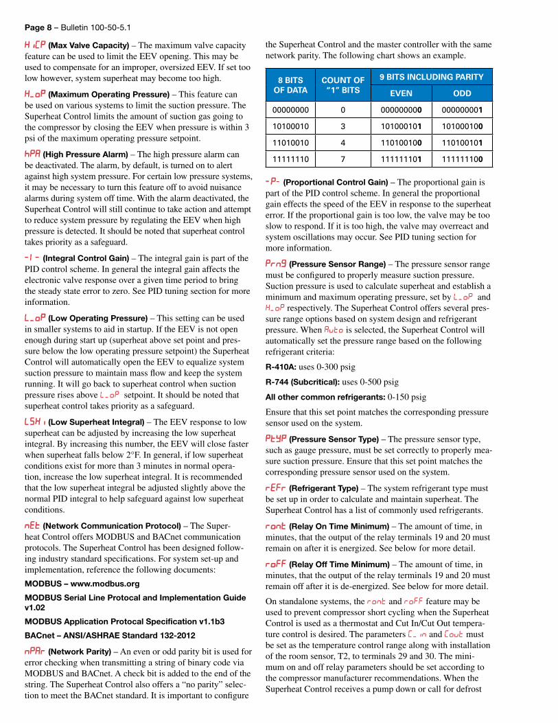
nPAr (Network Parity) – An even or odd parity bit is used for error checking when transmitting a string of binary code via MODBUS and BACnet. A check bit is added to the end of the string. The Superheat Control also offers a “no parity” selec-tion to meet the BACnet standard. It is important to configure
the Superheat Control and the master controller with the same network parity. The following chart shows an example.
8 BITSOF DATA
COUNT OF “1” BITS
9 BITS INCLUDING PARITY
EVEN ODD
00000000 0 000000000 000000001
10100010 3 101000101 101000100
11010010 4 110100100 110100101
11111110 7 111111101 111111100
P (Proportional Control Gain) – The proportional gain is part of the PID control scheme. In general the proportional gain effects the speed of the EEV in response to the superheat error. If the proportional gain is too low, the valve may be too slow to respond. If it is too high, the valve may overreact and system oscillations may occur. See PID tuning section for more information.
Prn (Pressure Sensor Range) – The pressure sensor range must be configured to properly measure suction pressure. Suction pressure is used to calculate superheat and establish a minimum and maximum operating pressure, set by _P and H_P respectively. The Superheat Control offers several pres-sure range options based on system design and refrigerant pressure. When Avt is selected, the Superheat Control will automatically set the pressure range based on the following refrigerant criteria:
R-410A: uses 0-300 psig
R-744 (Subcritical): uses 0-500 psig
All other common refrigerants: 0-150 psig
Ensure that this set point matches the corresponding pressure sensor used on the system.
Ptp (Pressure Sensor Type) – The pressure sensor type, such as gauge pressure, must be set correctly to properly mea-sure suction pressure. Ensure that this set point matches the corresponding pressure sensor used on the system.
rer (Refrigerant Type) – The system refrigerant type must be set up in order to calculate and maintain superheat. The Superheat Control has a list of commonly used refrigerants.
rnt (Relay On Time Minimum) – The amount of time, in minutes, that the output of the relay terminals 19 and 20 must remain on after it is energized. See below for more detail.
r (Relay Off Time Minimum) – The amount of time, in minutes, that the output of the relay terminals 19 and 20 must remain off after it is de-energized. See below for more detail.
On standalone systems, the rnt and r feature may be used to prevent compressor short cycling when the Superheat Control is used as a thermostat and Cut In/Cut Out tempera-ture control is desired. The parameters C_n and Cvt must be set as the temperature control range along with installation of the room sensor, T2, to terminals 29 and 30. The mini-mum on and off relay parameters should be set according to the compressor manufacturer recommendations. When the Superheat Control receives a pump down or call for defrost
Bulletin 100-50-5.1 – Page 9
from the dry contact at T3 temperature sensor input, terminals 27 and 28, the system will not execute the procedure to pump down until the minimum relay time has expired.
WARNING: The default setting for the Minimum Relay On and Off time is 0 minutes. For a stand-alone system these values may be adjusted to prevent compressor short cycling.
NOTE: Use caution. An oversized compressor can cause low case temperature during Minimum Relay On Time cycle set by rnt.
SHSP (Superheat Set Point) – The superheat set point is the control variable. The Superheat Control uses system suction pressure and temperature to calculate and maintain superheat for a given refrigerant type.
SPS (Stepper Position) – The EEV position is shown on the display real time in percent open. The position may also be read thru MODBUS or BACnet.
Stt (Stepper Timeout Override) – When the Stepper Time-out Override is placed in the ‘on’ position, the system will remain in manual valve mode indefinitely. The standard 60 minute timeout is not used. It should be noted that the setpoint parameter menu must be exited before changes are saved. The valve position shown under SPS will blink when the timeout is disabled. See Advanced Features section for more informa-tion on manual valve mode.
NOTE: Use caution and monitor superheat while in manu-al valve mode. To avoid floodback, start with the valve in a low position. Never leave the system unattended while in manual mode.
Step (Stepper Valve Type/Stroke) – The electronic valve type must be set correctly to match the valve that is used on the system. The type refers to the valve stroke, which typi-cally is 2500 or 6386 steps.
SvPS (Supermarket Mode) – Supermarket Mode may be used on large refrigeration systems; typically on controllers that are used in refrigerated case line ups. This mode has a unique algorithm to improve both case temperature pull down and steady state control. If the Superheat Control is used on standalone systems or systems with quick transient changes in load, it is recommended to turn this mode off and manually tune the PID parameters for the system. See PID tuning sec-tion for more information.
ttp (Temperature Sensor Type) – The temperature sensor type, such as 3K, must be set correctly to properly measure temperature and calculate superheat. The Superheat Control offers several types of temperature sensors; however, all temperature sensors must be of the same type per controller. Ensure that this set point matches the corresponding tempera-ture sensor used on the system.
Un_P (Unit Type Pressure) – The pressure sensor units, such as PSI, must be set correctly to properly measure and display suction pressure.
Un_ (Unit Type Temperature) – The temperature sensor units, such as Fahrenheit, must be set correctly to properly measure and display temperature.
5. Display NetworkingA Kelvin IId remote display unit can be connected to another Superheat Control in order to set up that controller, view that controller’s process values, and change setpoints.
To network a Superheat Control without display with a Kelvin IId (remote display unit):
1. Connect the two controllers with a Cat-5 Ethernet cable.2. The remote display unit will access the Superheat
Control.3. Set up the Superheat Control (Section 2 - Setup).
To network a Superheat Control without display with a Superheat Control (with display):
1. Connect the 2 controllers with a Cat-5 Ethernet cable.2. The Superheat Control with display must have its CAdr
parameter (Display Address) set to 1-99 to enable display networking. Navigate to “End” in the process variables display of the Superheat Control with Display and press the SELECT knob to select a different control-ler on the display network. (Controller should display “c”)Note: “End” is not available if “CAdr” is 0.
3. Turn the SELECT knob to find the Superheat Control without display (2 is default for the Superheat Control without display), and press the knob to connect.
4. After a connection is established the display should switch from “----” to the firmware version of the Superheat Control with display followed by the setup screen (if the controller has not been set up as described in Section 2).
The local controller is listed as c. To view a different controller on the display network, rotate the SELECT knob to CAdr and then press and release the knob. Rotate the knob to select the address of a controller. Once the address is selected it will take a moment to boot up. Setpoints on any control-ler can be changed as described in Section 3 - Setpoint Menu Operation.
The CAdr of a Superheat Control without display can also be set through Modbus.
Multiple ControllersThe CAdr of a Superheat Control without display, display address 3-99, must be set individually using a Kelvin IId or through Modbus.
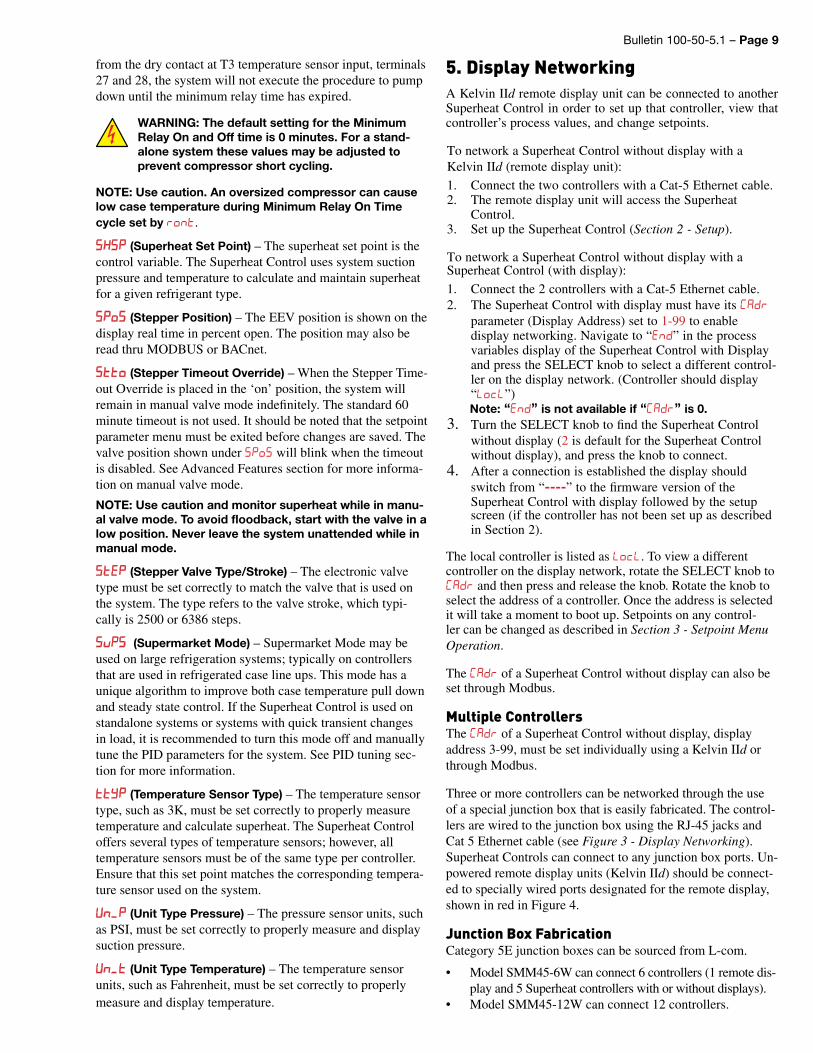
Three or more controllers can be networked through the use of a special junction box that is easily fabricated. The control-lers are wired to the junction box using the RJ-45 jacks and Cat 5 Ethernet cable (see Figure 3 - Display Networking). Superheat Controls can connect to any junction box ports. Un-powered remote display units (Kelvin IId) should be connect-ed to specially wired ports designated for the remote display, shown in red in Figure 4.
Junction Box Fabrication Category 5E junction boxes can be sourced from L-com.
• Model SMM45-6W can connect 6 controllers (1 remote dis-play and 5 Superheat controllers with or without displays).
• Model SMM45-12W can connect 12 controllers.
Page 10 – Bulletin 100-50-5.1
Kelvin IId remote displays, being unpowered, must be con-nected to an energized port (red jacks in Figure 3), with a powered controller plugged into the other red jack. If all the networked controllers are powered models, no special wiring (red jacks) is necessary.
To wire a junction box, punch down all blue and blue/white wires. To wire a pair of energized (red) jacks, punch down brown and brown/white wires between 2 jacks. See Figure 4.
6. Controller NetworkingThe Sporlan Superheat Control can communicate with a Modbus communication master via RS485 to transfer process values and setpoints. See Appendix J - Modbus Memory Map.
The Kelvin II supports only the RTU transmission mode. The serial settings are:• 9600 baud (default), 19200 baud, 38400 baud• 8 data bits• 1 stop bit• Even parity (default), odd parity, no parity
ScalingFor better precision, scaling is used for Bar or Celsius units. PSI and Fahrenheit are whole numbers and have no scaling.
Celsius values transferred via Modbus are 10X. For example, a value of 45 will be transferred for the superheat when the actual superheat temperature is 4.5°C. Remember this when changing a setpoint.
Bar values transferred via Modbus are 100X. For example a value of 1034 will be transferred for the Maximum Operating Pressure when the actual pressure is 10.34 Bar. Remember this when changing a setpoint.
Figure 3 - Display Networking Figure 4 - Wiring the Powered (Red) Jacks
Kelvin IId
Superheat Controlwith or without Display
Superheat Controlwith or without Display
Superheat Controlwith or without Display
Superheat Controlwith or without Display
Junction Box
SetupThe Sporlan Superheat Control can be networked to com-municate process variables back to a master controller. This information can be used for verifying system performance or updating individual setpoints via RS-485 and PC interface. Data can be accessed remotely through the master controller. For further information on remote monitoring, see the docu-mentation for the master controller.
Prior to connecting the network, each controller must be assigned a separate address on the Modbus network, Addr. Refer to Section 3 – Setpoint Menu Operation to enter the Setpoint menu. Once in the Setpoint menu, scroll to Add and assign each controller on the network an individual address. Note that no two controllers can have the same address. Default address for each controller is ‘1’.
NOTE: Add is the Modbus address, CAd is the controller display address.
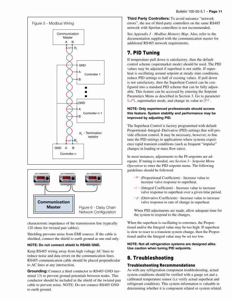
Modbus Connection RequirementsSee Figure 5 - Modbus Wiring.
Wire Type: 18 AWG Universal Twisted Pair
Maximum Number of Network Nodes: 100
Maximum Run Length: 4000 ft
Recommended Network Configuration: Daisy Chain, a single continuous transmission line from one end to the other. Other configurations involving triple-lug connections, such as star, are not recommended. See Figure 6.
Noise Reduction: Termination resistance (RT in Figure 5) is recommended to reduce reflections and noise on the data transmission lines. Place the resistance at the extreme ends of the cable, with the resistance value matching the
Bulletin 100-50-5.1 – Page 11
Figure 5 - Modbus Wiring
Controller 1
GND
RT
RT
CommunicationMaster
A B
B
Controller n
RT- Termination
resistor
B
A
Controller n-1
GND
B
A
AGND
characteristic impedance of the transmission line (typically 120 ohms for twisted pair cables).
Shielding prevents noise from EMI sources. If the cable is shielded, connect the shield to earth ground at one end only.
NOTE: Do not connect shield to RS485 GND.
Keep RS485 wiring away from high voltage AC lines to reduce noise and data errors on the communication lines. RS485 communication cable should be placed perpendicular to AC lines at any intersection.
Grounding: Connect a third conductor to RS485 GND (ter-minal 13) to prevent ground potentials between nodes. This conductor should be included in the shield of the twisted pair cable to prevent noise. NOTE: Do not connect RS485 GND to earth ground.
CommunicationMaster Figure 6 - Daisy Chain
Network Configuration
Third Party Controllers: To avoid nuisance “network errors”, the use of third-party controllers on the same RS485 network with Sporlan controllers is not recommended.
See Appendix J - Modbus Memory Map. Also, refer to the documentation supplied with the communication master for additional RS485 network requirements.
7. PID TuningIf temperature pull down is satisfactory, then the default control scheme (supermarket mode) should be used. The PID values may be adjusted if superheat is not stable. If super-heat is oscillating around setpoint at steady state conditions, reduce PID settings to half of existing values. If pull down is not satisfactory, then the Superheat Control can be con-figured into a standard PID scheme that can be fully adjust-able. This feature can be accessed by entering the Setpoint Parameters Menu as described in Section 3. Go to parameter SvPS, supermarket mode, and change its value to FF.
NOTE: Only experienced professionals should access this feature. System stability and performance may be improved by adjusting PID.
The Superheat Control is factory programmed with default Proportional–Integral–Derivative (PID) settings that will pro-vide efficient control. It may be necessary, however, to fine tune the PID settings in applications where systems experi-ence rapid transient conditions (such as frequent “impulse” changes in loading or mass flow rates).
In most instances, adjustments to the PI setpoints are ad-equate. If tuning is needed, see Section 3 - Setpoint Menu Operation to enter the PID setpoint menu. The following guidelines should be followed:
• p (Proportional Coefficient) - Increase value to increase valve response to superheat.
• (Integral Coefficient) - Increase value to increase valve response to superheat over a given time period.
• d (Derivative Coefficient) - Increase value to increase valve response to rate of change in superheat.
• • When PID adjustments are made, allow adequate time for
the system to respond to the changes.
When the superheat is oscillating to extremes, the Propor-tional and/or the Integral value may be too high. If superheat is slow to react to a transient system change, then the Propor-tional and/or the Integral value may be set too low.
NOTE: Not all refrigeration systems are designed alike. Use caution when tuning PID setpoints.
8. TroubleshootingTroubleshooting RecommendationsAs with any refrigeration component troubleshooting, actual system conditions should be verified with a gauge set and a calibrated temperature sensor (i.e verify actual superheat and refrigerant condition). This system information is valuable in determining whether it is component related or system related.
Page 12 – Bulletin 100-50-5.1
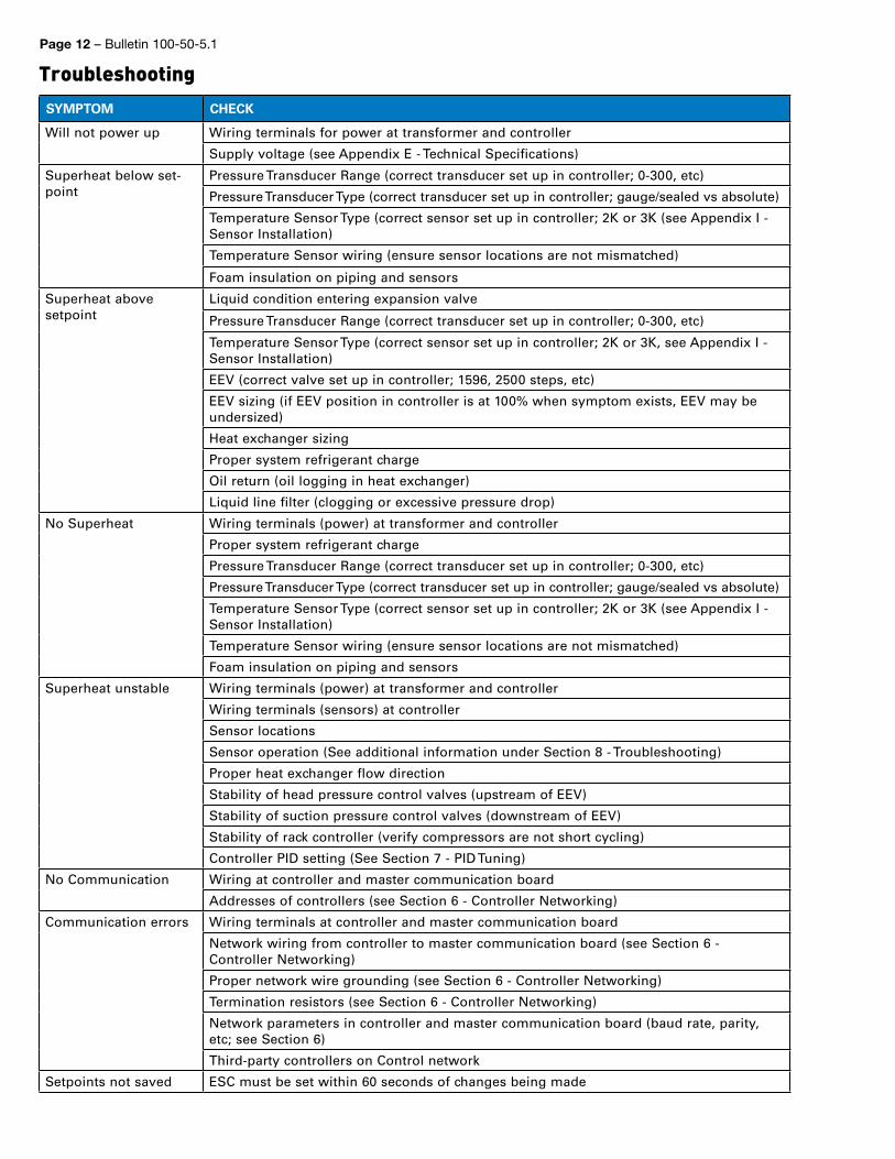
TroubleshootingSYMPTOM CHECK
Will not power up Wiring terminals for power at transformer and controller
Supply voltage (see Appendix E - Technical Specifications)
Superheat below set-point
Pressure Transducer Range (correct transducer set up in controller; 0-300, etc)
Pressure Transducer Type (correct transducer set up in controller; gauge/sealed vs absolute)
Temperature Sensor Type (correct sensor set up in controller; 2K or 3K (see Appendix I - Sensor Installation)
Temperature Sensor wiring (ensure sensor locations are not mismatched)
Foam insulation on piping and sensors
Superheat above setpoint
Liquid condition entering expansion valve
Pressure Transducer Range (correct transducer set up in controller; 0-300, etc)
Temperature Sensor Type (correct sensor set up in controller; 2K or 3K, see Appendix I - Sensor Installation)
EEV (correct valve set up in controller; 1596, 2500 steps, etc)
EEV sizing (if EEV position in controller is at 100% when symptom exists, EEV may be undersized)
Heat exchanger sizing
Proper system refrigerant charge
Oil return (oil logging in heat exchanger)
Liquid line filter (clogging or excessive pressure drop)
No Superheat Wiring terminals (power) at transformer and controller
Proper system refrigerant charge
Pressure Transducer Range (correct transducer set up in controller; 0-300, etc)
Pressure Transducer Type (correct transducer set up in controller; gauge/sealed vs absolute)
Temperature Sensor Type (correct sensor set up in controller; 2K or 3K (see Appendix I - Sensor Installation)
Temperature Sensor wiring (ensure sensor locations are not mismatched)
Foam insulation on piping and sensors
Superheat unstable Wiring terminals (power) at transformer and controller
Wiring terminals (sensors) at controller
Sensor locations
Sensor operation (See additional information under Section 8 - Troubleshooting)
Proper heat exchanger flow direction
Stability of head pressure control valves (upstream of EEV)
Stability of suction pressure control valves (downstream of EEV)
Stability of rack controller (verify compressors are not short cycling)
Controller PID setting (See Section 7 - PID Tuning)
No Communication Wiring at controller and master communication board
Addresses of controllers (see Section 6 - Controller Networking)
Communication errors Wiring terminals at controller and master communication board
Network wiring from controller to master communication board (see Section 6 - Controller Networking)
Proper network wire grounding (see Section 6 - Controller Networking)
Termination resistors (see Section 6 - Controller Networking)
Network parameters in controller and master communication board (baud rate, parity, etc; see Section 6)
Third-party controllers on Control network
Setpoints not saved ESC must be set within 60 seconds of changes being made
Bulletin 100-50-5.1 – Page 13
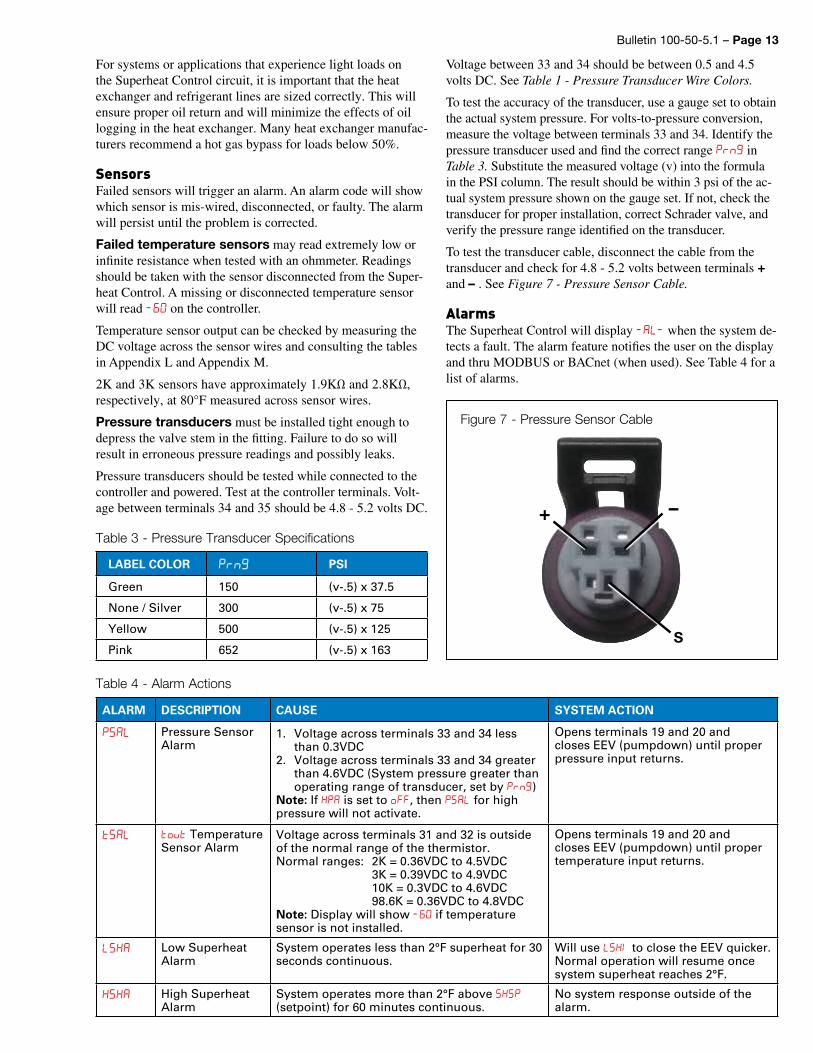
Voltage between 33 and 34 should be between 0.5 and 4.5 volts DC. See Table 1 - Pressure Transducer Wire Colors.
To test the accuracy of the transducer, use a gauge set to obtain the actual system pressure. For volts-to-pressure conversion, measure the voltage between terminals 33 and 34. Identify the pressure transducer used and find the correct range Prn in Table 3. Substitute the measured voltage (v) into the formula in the PSI column. The result should be within 3 psi of the ac-tual system pressure shown on the gauge set. If not, check the transducer for proper installation, correct Schrader valve, and verify the pressure range identified on the transducer.
To test the transducer cable, disconnect the cable from the transducer and check for 4.8 - 5.2 volts between terminals + and – . See Figure 7 - Pressure Sensor Cable.
AlarmsThe Superheat Control will display A when the system de-tects a fault. The alarm feature notifies the user on the display and thru MODBUS or BACnet (when used). See Table 4 for a list of alarms.
ALARM DESCRIPTION CAUSE SYSTEM ACTION
PSA Pressure Sensor Alarm
1. Voltage across terminals 33 and 34 less than 0.3VDC
2. Voltage across terminals 33 and 34 greater than 4.6VDC (System pressure greater than operating range of transducer, set by P)
Note: If HPA is set to , then PSA for high pressure will not activate.
Opens terminals 19 and 20 and closes EEV (pumpdown) until proper pressure input returns.
tSA vt Temperature Sensor Alarm
Voltage across terminals 31 and 32 is outside of the normal range of the thermistor. Normal ranges: 2K = 0.36VDC to 4.5VDC 3K = 0.39VDC to 4.9VDC 10K = 0.3VDC to 4.6VDC 98.6K = 0.36VDC to 4.8VDC Note: Display will show if temperature sensor is not installed.
Opens terminals 19 and 20 and closes EEV (pumpdown) until proper temperature input returns.
SHA Low Superheat Alarm
System operates less than 2°F superheat for 30 seconds continuous.
Will use SH to close the EEV quicker. Normal operation will resume once system superheat reaches 2°F.
HSHA High Superheat Alarm
System operates more than 2°F above SHSP (setpoint) for 60 minutes continuous.
No system response outside of the alarm.
Table 4 - Alarm Actions
Figure 7 - Pressure Sensor Cable
S
–+
For systems or applications that experience light loads on the Superheat Control circuit, it is important that the heat exchanger and refrigerant lines are sized correctly. This will ensure proper oil return and will minimize the effects of oil logging in the heat exchanger. Many heat exchanger manufac-turers recommend a hot gas bypass for loads below 50%.
Sensors Failed sensors will trigger an alarm. An alarm code will show which sensor is mis-wired, disconnected, or faulty. The alarm will persist until the problem is corrected.
Failed temperature sensors may read extremely low or infinite resistance when tested with an ohmmeter. Readings should be taken with the sensor disconnected from the Super-heat Control. A missing or disconnected temperature sensor will read on the controller.
Temperature sensor output can be checked by measuring the DC voltage across the sensor wires and consulting the tables in Appendix L and Appendix M.
2K and 3K sensors have approximately 1.9KΩ and 2.8KΩ, respectively, at 80°F measured across sensor wires.
Pressure transducers must be installed tight enough to depress the valve stem in the fitting. Failure to do so will result in erroneous pressure readings and possibly leaks.
Pressure transducers should be tested while connected to the controller and powered. Test at the controller terminals. Volt-age between terminals 34 and 35 should be 4.8 - 5.2 volts DC.
LABEL COLOR Prn PSI
Green 150 (v-.5) x 37.5
None / Silver 300 (v-.5) x 75
Yellow 500 (v-.5) x 125
Pink 652 (v-.5) x 163
Table 3 - Pressure Transducer Specifications
Page 14 – Bulletin 100-50-5.1
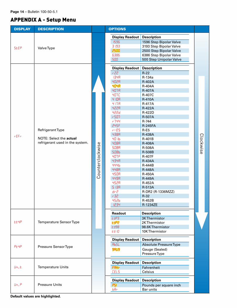
DISPLAY DESCRIPTION OPTIONS
StEp Valve Type
Display Readout Description1 1596 Step Bipolar Valve1 3193 Step Bipolar Valve 2500 Step Bipolar Valve 6386 Step Bipolar Valve 500 Step Unipolar Valve
rEFr
Refrigerant Type
NOTE: Select the actual refrigerant used in the system.
Display Readout Descriptionr R-2214 R-134a4 R-402A44 R-404A4 R-407A4C R-407C41 R-410A41 R-417A4 R-422A4d R-422Dr R-507Ar44 R-7444 R-245FAre R-E54 R-438A41 R-401B4 R-408AA R-508A R-508B4 R-407F44 R-434A444 R-444B44 R-448A4 R-450A44 R-449A4 R-452A1 R-513Adr R-DR2 (R-1336MZZ)r R-324 R-452B14 R-1234ZE
tt4p Temperature Sensor Type
Readout Descriptiontp 3K Thermistortp 2K Thermistort 98.6K Thermistort1 10K Thermistor
Pt4p Pressure Sensor Type
Display Readout DescriptionAS Absolute Pressure TypeAU Gauge (Sealed)
Pressure Type
Un_t Temperature Units Display Readout DescriptionFAH FahrenheitCES Celsius
Un_p Pressure UnitsDisplay Readout DescriptionPS Pounds per square inchA Bar units
APPENDIX A - Setup Menu
Coun
terc
lock
wis
e
Clockwise
Default values are highlighted.
Bulletin 100-50-5.1 – Page 15
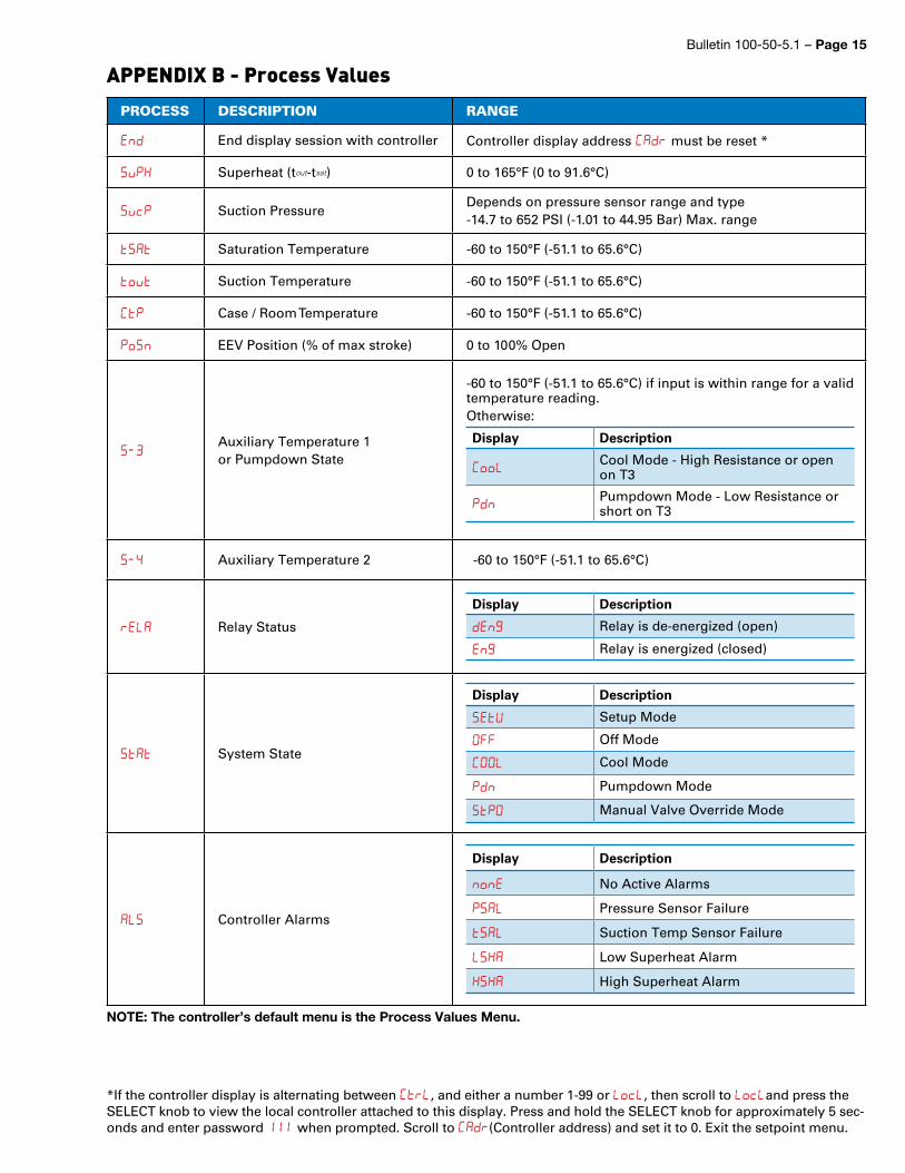
APPENDIX B - Process Values
PROCESS DESCRIPTION RANGE
End End display session with controller Controller display address CAD must be reset *
SvPH Superheat (tout-tsat) 0 to 165°F (0 to 91.6°C)
SvcP Suction PressureDepends on pressure sensor range and type-14.7 to 652 PSI (-1.01 to 44.95 Bar) Max. range
tSAt Saturation Temperature -60 to 150°F (-51.1 to 65.6°C)
tvt Suction Temperature -60 to 150°F (-51.1 to 65.6°C)
CtP Case / Room Temperature -60 to 150°F (-51.1 to 65.6°C)
PSn EEV Position (% of max stroke) 0 to 100% Open
SAuxiliary Temperature 1 or Pumpdown State
-60 to 150°F (-51.1 to 65.6°C) if input is within range for a valid temperature reading.Otherwise:
Display Description
C Cool Mode - High Resistance or open on T3
Pdn Pumpdown Mode - Low Resistance or short on T3
S4 Auxiliary Temperature 2 -60 to 150°F (-51.1 to 65.6°C)
rEA Relay Status
Display Description
dEn Relay is de-energized (open)
En Relay is energized (closed)
Stt System State
Display Description
SEtU Setup Mode
FF Off Mode
C Cool Mode
Pdn Pumpdown Mode
StP Manual Valve Override Mode
AS Controller Alarms
Display Description
nnE No Active Alarms
PSA Pressure Sensor Failure
tSA Suction Temp Sensor Failure
SHA Low Superheat Alarm
HSHA High Superheat Alarm
*If the controller display is alternating between Ctr, and either a number 1-99 or c, then scroll to cand press the SELECT knob to view the local controller attached to this display. Press and hold the SELECT knob for approximately 5 sec-onds and enter password 111 when prompted. Scroll to CAD(Controller address) and set it to 0. Exit the setpoint menu.
NOTE: The controller’s default menu is the Process Values Menu.
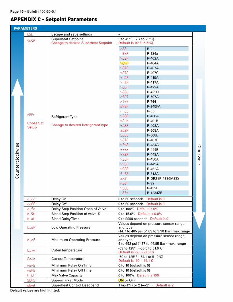
Page 16 – Bulletin 100-50-5.1
PARAMETERS
ESC Escape and save settings -
SHSP Superheat SetpointChange to desired Superheat Setpoint
5 to 45°F (2.7 to 25°C)Default is 10°F (5.5°C)
rEFr
Chosen at Setup
Refrigerant Type
Change to desired Refrigerant Type
r R-2214 R-134a4 R-402A44 R-404A4 R-407A4C R-407C41 R-410A41 R-417A4 R-422A4d R-422Dr R-507Ar44 R-7444 R-245FAre R-E54 R-438A41 R-401B4 R-408AA R-508A R-508B4 R-407F44 R-434A444 R-444B44 R-448A4 R-450A44 R-449A4 R-452A1 R-513Adr R-DR2 (R-1336MZZ)r R-324 R-452B14 R-1234ZE
d_n Delay On 0 to 60 seconds Default is 0d Delay Off 0 to 60 seconds Default is 0d_t Delay Step Position Open of Valve 0 to 100% Default is 0%_t Bleed Step Position of Valve % 0 to 15.0% Default is 0.0%_d Bleed Delay Time 0 to 9999 seconds Default is 0
_p Low Operating PressureValues depend on pressure sensor range and type-14.7 to 485 psi (-1.03 to 9.30 Bar) max.range
H_p Maximum Operating PressureValues depend on pressure sensor range and type5 to 652 psi (1.37 to 44.95 Bar) max. range
C_n Cut-in Temperature -59 to 125°F (-50.5 to 51.6°C) Default is -59 (-50.5 C)
Cvt Cut-out Temperature -60 to 125°F (-51.1 to 51.0°C)Default is -60 ( -51.1 C)
rnt Minimum Relay On Time 0 to 10 (default is 0)rFt Minimum Relay Off Time 0 to 10 (default is 0)HCP Max Valve Capacity 0 to 100% Default is 100Sup Supermarket Mode ON or OFF dnd Superheat Control Deadband 1 (+/-1°F) or 2 (+/-2°F) Default is 2
APPENDIX C - Setpoint ParametersCo
unte
rclo
ckw
ise Clockwise
Default values are highlighted.
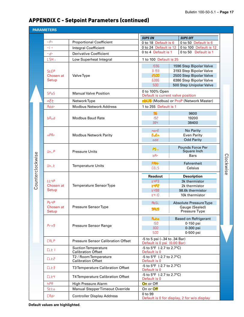
Bulletin 100-50-5.1 – Page 17
PARAMETERS
P Proportional Coefficient
Integral Coefficient
d Derivative Coefficient
SH Low Superheat Integral 1 to 100 Default is 25
StEpChosen at Setup
Valve Type
1 1596 Step Bipolar Valve1 3193 Step Bipolar Valve 2500 Step Bipolar Valve 6386 Step Bipolar Valve 500 Step Unipolar Valve
SPS Manual Valve Position 0 to 100% OpenDefault is current valve position
nEt Network Type nbUS (Modbus) or ProP (Network Master)
Addr Modbus Network Address 1 to 255 Default is 1
vD Modbus Baud Rate 96001 192004 38400
nPAr Modbus Network Paritynne No ParityEvEn Even Paritydd Odd Parity
Un_P Pressure UnitsP Pounds Force Per
Square InchAr Bars
Un_t Temperature UnitsFAHr FahrenheitCES Celsius
tt4pChosen at Setup
Temperature Sensor Type
Readout Descriptiont4p 3k thermistort4p 2k thermistort4 98.6k thermistort41 10k thermistor
Pt4pChosen at Setup
Pressure Sensor TypeAS Absolute Pressure Type
AU Gauge (Sealed) Pressure Type
Prn Pressure Sensor Range
Avt Based on Refrigerant1 0-150 psi 0-300 psi 0-500 psi
CAP Pressure Sensor Calibration Offset -5 to 5 psi (-.34 to .34 Bar)Default is 0 psi (0.00 Bar)
C1 Suction TemperatureCalibration Offset
-5 to 5°F (-2.7 to 2.7°C)Default is 0
C T2 / Room TemperatureCalibration Offset
-5 to 5°F (-2.7 to 2.7°C)Default is 0
C T3 Temperature Calibration Offset -5 to 5°F (-2.7 to 2.7°C)Default is 0
C4 T4 Temperature Calibration Offset -5 to 5°F (-2.7 to 2.7°C)Default is 0
p High Pressure Alarm On or Offtt Manual Stepper Timeout Override On or Off
CAdr Controller Display Address 0 to 99Default is 0 for display, 2 for w/o display
APPENDIX C - Setpoint Parameters (continued)Clockw
ise
Coun
terc
lock
wis
e
Default values are highlighted.
SUPS ON SUPS OFF0 to 18 Default is 6 0 to 50 Default is 60 to 24 Default is 12 0 to 100 Default is 120 to 4 Default is 1 0 to 50 Default is 1
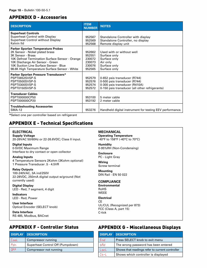
Page 18 – Bulletin 100-50-5.1
APPENDIX F - Controller StatusDISPLAY DESCRIPTION
C Compressor running
pdn Superheat Control Off (Pumpdown)
Compressor not running
APPENDIX G - Miscellaneous DisplaysDISPLAY DESCRIPTION
End Press SELECT knob to exit menu
AD The wrong password has been entered
c Shows that readings refer to current controller
Ctr Shows which controller is displayed
ELECTRICALSupply Voltage 20-26VAC 50/60Hz or 22-26.6VDC; Class II input.
Digital Inputs 0-5VDC Maximum Range Interface to dry contact or open collector
Analog Inputs 4 Temperature Sensors 2Kohm (3Kohm optional) 1 Pressure Transducer .5 - 4.5VR
Relay Outputs 100-240VAC, 3A ind/250V 22-28VDC, 250mA digital output w/ground (Not currently used)
Digital Display LED - Red, 7 segment, 4 digit
Indicators LED - Red, Power
User Interface Optical Encoder (SELECT knob)
Data Interface RS 485, Modbus, BACnet
MECHANICALOperating Temperature -40°F to 158°F (-40°C to 70°C)
Humidity 0-95%RH (Non-Condensing)
Enclosure PC - Light Gray
Wiring Screw terminal
Mounting DIN Rail - EN 50 022
COMPLIANCEEnvironmentalRoHS WEEE
ElectricalCE UL/CUL (Recognized per 873)FCC (Class A, part 15) C-tick
APPENDIX E - Technical Specifications
APPENDIX D - Accessories
DESCRIPTIONITEM NUMBER
NOTES
Superheat ControlsSuperheat Control with DisplaySuperheat Control without DisplayKelvin IId
952567952569952568
Standalone Controller with displayStandalone Controller, no displayRemote display unit
Parker Sporlan Temperature Probes2K Sensor - Nickel plated brass 3K Sensor - Brass10K Defrost Termination Surface Sensor - Orange10K Discharge Air Sensor - Green10K Suction Line Surface Sensor - Blue98.6K High Temperature Surface Sensor - White
952662 952551 230072230073230076952565
Used with or without wellSurface onlySurface onlyAir onlySurface onlySurface only
Parker Sporlan Pressure Transducers*PSPT0652SVSP-SPSPT0500SVSP-SPSPT0300SVSP-SPSPT0150SVSP-S
952579 952576 952574 952572
0-652 psis transducer (R744) 0-500 psis transducer (R744)0-300 psis transducer (R410A)0-150 psis transducer (all other refrigerants)
Transducer CablesPSPT000000CP50PSPT000000CP20
953100 953192
5 meter cable2 meter cable
Troubleshooting AccessoriesSMA-12 953276 Handheld digital instrument for testing EEV performance.
*Select one per controller based on refrigerant
Bulletin 100-50-5.1 – Page 19
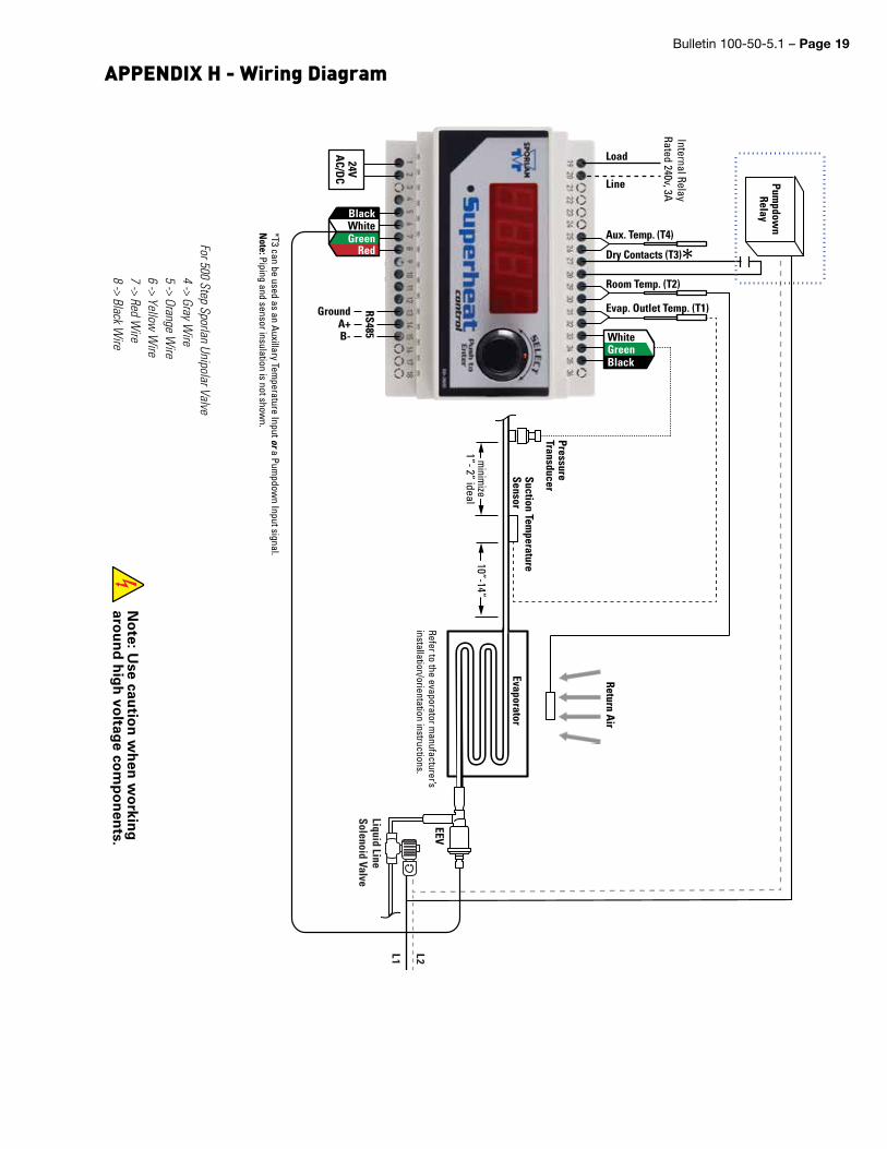
APPENDIX H - Wiring Diagram
No
te: Use cau
tion
wh
en w
orkin
g
arou
nd
hig
h vo
ltage co
mp
on
ents.
Dry Contacts (T3)
Evap. Outlet Temp. (T1)
Room Temp. (T2)
WhiteGreenBlack
Black
24VA
C/DC
RS485
WhiteGreen
Red
B-
GroundA+
Suction Temperature
Sensor
PressureTransducer
Pumpdow
nRelay
L1 L2
EEV
Load
Line
Liquid Line Solenoid Valve
10”-14”m
inimize
1”- 2” ideal
Evaporator
Aux. Temp. (T4)
Internal RelayRated 240v, 3A
**T3 can be used as an Auxillary Temperature Input or a Pum
pdown Input signal.
Note: Piping and sensor insulation is not show
n.
Refer to the evaporator manufacturer’s
installation/orientation instructions.
WhiteGreenBlack
BlackWhiteGreen
Red
Return Air
For 500 Step Sporlan Unipolar Valve4 -> Gray W
ire5 -> Orange W
ire6 -> Yellow
Wire
7 -> Red Wire
8 -> Black Wire
Page 20 – Bulletin 100-50-5.1
Refer to Appendix H - Wiring Diagram for sensor locations.
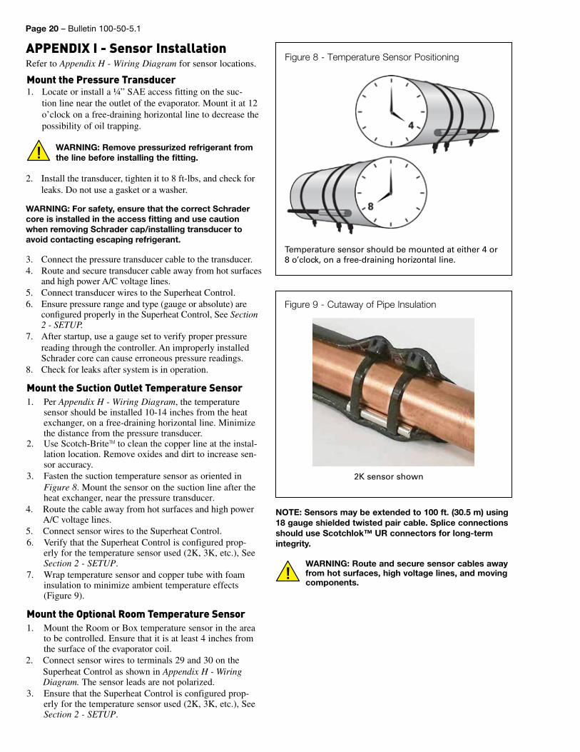
Mount the Pressure Transducer1. Locate or install a ¼” SAE access fitting on the suc-
tion line near the outlet of the evaporator. Mount it at 12 o’clock on a free-draining horizontal line to decrease the possibility of oil trapping.
WARNING: Remove pressurized refrigerant from the line before installing the fitting.
2. Install the transducer, tighten it to 8 ft-lbs, and check for leaks. Do not use a gasket or a washer.
WARNING: For safety, ensure that the correct Schrader core is installed in the access fitting and use caution when removing Schrader cap/installing transducer to avoid contacting escaping refrigerant.
3. Connect the pressure transducer cable to the transducer.4. Route and secure transducer cable away from hot surfaces
and high power A/C voltage lines.5. Connect transducer wires to the Superheat Control.6. Ensure pressure range and type (gauge or absolute) are
configured properly in the Superheat Control, See Section 2 - SETUP.
7. After startup, use a gauge set to verify proper pressure reading through the controller. An improperly installed Schrader core can cause erroneous pressure readings.
8. Check for leaks after system is in operation.
Mount the Suction Outlet Temperature Sensor1. Per Appendix H - Wiring Diagram, the temperature
sensor should be installed 10-14 inches from the heat exchanger, on a free-draining horizontal line. Minimize the distance from the pressure transducer.
2. Use Scotch-BriteTM to clean the copper line at the instal-lation location. Remove oxides and dirt to increase sen-sor accuracy.
3. Fasten the suction temperature sensor as oriented in Figure 8. Mount the sensor on the suction line after the heat exchanger, near the pressure transducer.
4. Route the cable away from hot surfaces and high power A/C voltage lines.
5. Connect sensor wires to the Superheat Control.6. Verify that the Superheat Control is configured prop-
erly for the temperature sensor used (2K, 3K, etc.), See Section 2 - SETUP.
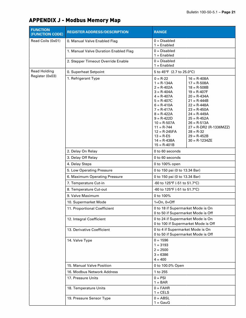
7. Wrap temperature sensor and copper tube with foam insulation to minimize ambient temperature effects (Figure 9).
Mount the Optional Room Temperature Sensor1. Mount the Room or Box temperature sensor in the area
to be controlled. Ensure that it is at least 4 inches from the surface of the evaporator coil.
2. Connect sensor wires to terminals 29 and 30 on the Superheat Control as shown in Appendix H - Wiring Diagram. The sensor leads are not polarized.
3. Ensure that the Superheat Control is configured prop-erly for the temperature sensor used (2K, 3K, etc.), See Section 2 - SETUP.
Figure 8 - Temperature Sensor PositioningAPPENDIX I - Sensor Installation
Temperature sensor should be mounted at either 4 or 8 o’clock, on a free-draining horizontal line.
NOTE: Sensors may be extended to 100 ft. (30.5 m) using 18 gauge shielded twisted pair cable. Splice connections should use Scotchlok™ UR connectors for long-term integrity.
WARNING: Route and secure sensor cables away from hot surfaces, high voltage lines, and moving components.
Figure 9 - Cutaway of Pipe Insulation
2K sensor shown
Bulletin 100-50-5.1 – Page 21
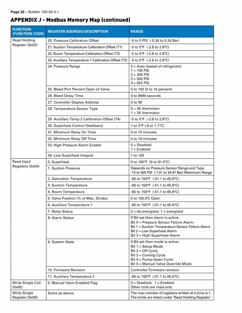
APPENDIX J - Modbus Memory MapFUNCTION (FUNCTION CODE)
REGISTER ADDRESS/DESCRIPTION RANGE
Read Coils (0x01) 0. Manual Valve Enabled Flag 0 = Disabled 1 = Enabled
1. Manual Valve Duration Enabled Flag 0 = Disabled 1 = Enabled
2. Stepper Timeout Override Enable 0 = Disabled 1 = Enabled
Read Holding Register (0x03)
0. Superheat Setpoint 5 to 45°F (2.7 to 25.0°C)
1. Refrigerant Type 0 = R-22 1 = R-134A 2 = R-402A 3 = R-404A 4 = R-407A 5 = R-407C 6 = R-410A 7 = R-417A8 = R-422A 9 = R-422D10 = R-507A 11 = R-744 12 = R-245FA 13 = R-E5 14 = R-438A15 = R-401B
16 = R-408A17 = R-508A18 = R-508B 19 = R-407F 20 = R-434A 21 = R-444B 22 = R-448A 23 = R-450A 24 = R-449A 25 = R-452A 26 = R-513A 27 = R-DR2 (R-1336MZZ) 28 = R-32 29 = R-452B30 = R-1234ZE
2. Delay On Relay 0 to 60 seconds
3. Delay Off Relay 0 to 60 seconds
4. Delay Steps 0 to 100% open
5. Low Operating Pressure 0 to 150 psi (0 to 13.34 Bar)
6. Maximum Operating Pressure 0 to 150 psi (0 to 13.34 Bar)
7. Temperature Cut-in -60 to 125°F (-51 to 51.7°C)
8. Temperature Cut-out -60 to 125°F (-51 to 51.7°C)
9. Valve Maximum 0 to 100%
10. Supermarket Mode 1=On, 0=Off
11. Proportional Coefficient 0 to 18 if Supermarket Mode is On0 to 50 if Supermarket Mode is Off
12. Integral Coefficient 0 to 24 if Supermarket Mode is On0 to 100 if Supermarket Mode is Off
13. Derivative Coefficient 0 to 4 if Supermarket Mode is On0 to 50 if Supermarket Mode is Off
14. Valve Type 0 = 1596 1 = 3193 2 = 25003 = 6386 4 = 400
15. Manual Valve Position 0 to 100.0% Open
16. Modbus Network Address 1 to 255
17. Pressure Units 0 = PSI 1 = BAR
18. Temperature Units 0 = FAHR 1 = CELS
19. Pressure Sensor Type 0 = ABSL 1 = GauG
Page 22 – Bulletin 100-50-5.1
APPENDIX J - Modbus Memory Map (continued)FUNCTION (FUNCTION CODE)
REGISTER ADDRESS/DESCRIPTION RANGE
Read Holding Register (0x03)
20. Pressure Calibration Offset -5 to 5 PSI (-0.34 to 0.34 Bar)
21. Suction Temperature Calibration Offset (T1) -5 to 5°F (-2.8 to 2.8°C)
22. Room Temperature Calibration Offset (T2) -5 to 5°F (-2.8 to 2.8°C)
23. Auxiliary Temperature 1 Calibration Offset (T3) -5 to 5°F (-2.8 to 2.8°C)
24. Pressure Range 0 = Auto (based of refrigerant)1 = 150 PSI 2 = 300 PSI 3 = 500 PSI4 = 652 PSI
25. Bleed Port Percent Open of Valve 0 to 150 (0 to 15 percent)
26. Bleed Delay Time 0 to 9999 seconds
27. Controller Display Address 0 to 99
28. Temperature Sensor Type 0 = 3K thermistor1 = 2K thermistor
29. Auxillary Temp 2 Calibration Offset (T4) -5 to 5°F (-2.8 to 2.8°C)
30. Superheat Control Deadband 1 or 2°F (.6 or 1.1°C)
31. Minimum Relay On Time 0 to 10 minutes
32. Minimum Relay Off Time 0 to 10 minutes
33. High Pressure Alarm Enable 0 = Disabled 1 = Enabled
34. Low Superheat Integral 1 to 100
Read Input Registers (0x04)
0. Superheat 0 to 165°F (0 to 91.6°C)
1. Suction Pressure Depends on Pressure Sensor Range and Type-15 to 500 PSI (-1.01 to 34.47 Bar) Maximum Range
2. Saturation Temperature -60 to 150°F (-51.1 to 65.6°C)
3. Suction Temperature -60 to 150°F (-51.1 to 65.6°C)
4. Room Temperature -60 to 150°F (-51.1 to 65.6°C)
5. Valve Position (% of Max. Stroke) 0 to 100.0% Open
6. Auxiliary Temperature 1 -60 to 150°F (-51.1 to 65.6°C)
7. Relay Status 0 = de-energized, 1 = energized
8. Alarm Status If Bit set then alarm is active: Bit 0 = Pressure Sensor Failure Alarm Bit 1 = Suction Temperature Sensor Failure Alarm Bit 2 = Low Superheat AlarmBit 3 = High Superheat Alarm
9. System State If Bit set then mode is active: Bit 1 = Setup Mode Bit 2 = Off Cycle Bit 3 = Cooling Cycle Bit 4 = Pump-down Cycle Bit 5 = Manual Valve Override Mode
10. Firmware Revision Controller Firmware revision
11. Auxiliary Temperature 2 -60 to 150°F (-51.1 to 65.6°C)
Write Single Coil (0x05)
0. Manual Valve Enabled Flag 0 = Disabled, 1 = EnabledOther coils are read-only
Write Single Register (0x06)
Same as above. The max number of registers written at a time is 1. The limits are listed under ‘Read Holding Register.’
Bulletin 100-50-5.1 – Page 23
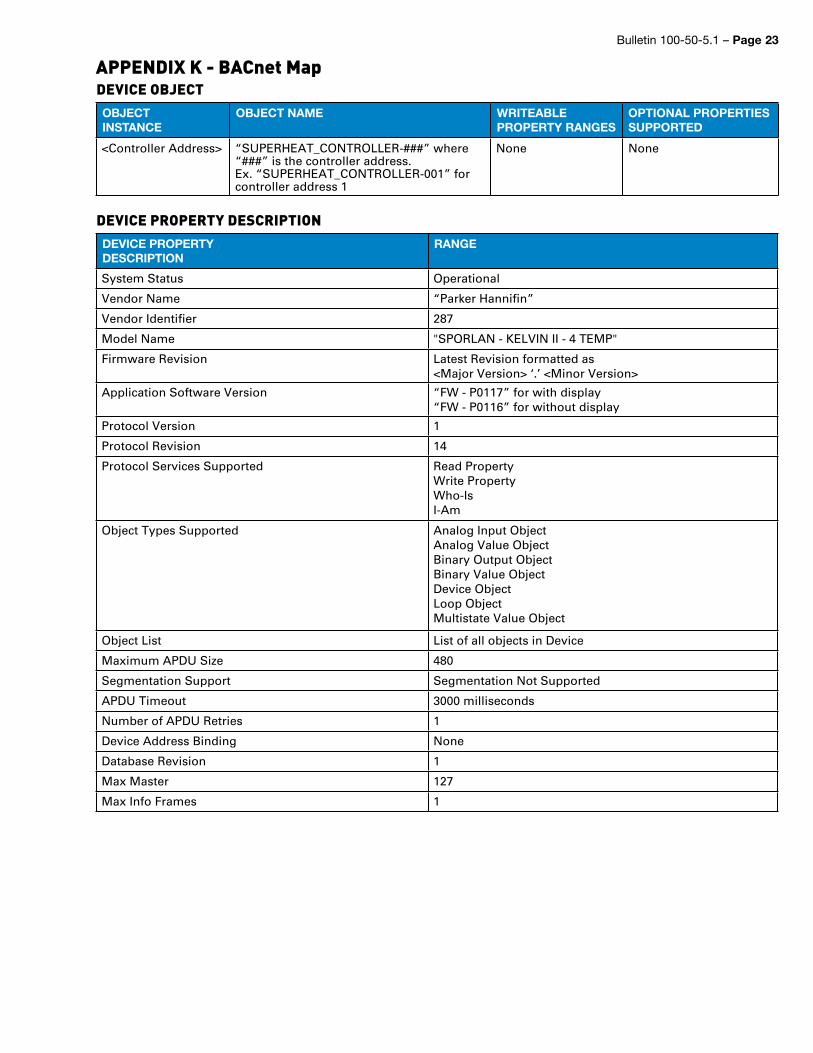
APPENDIX K - BACnet MapDEVICE OBJECTOBJECTINSTANCE
OBJECT NAME WRITEABLE PROPERTY RANGES
OPTIONAL PROPERTIES SUPPORTED
<Controller Address> “SUPERHEAT_CONTROLLER-###” where “###” is the controller address.Ex. “SUPERHEAT_CONTROLLER-001” for controller address 1
None None
DEVICE PROPERTY DESCRIPTIONDEVICE PROPERTY DESCRIPTION
RANGE
System Status Operational
Vendor Name “Parker Hannifin”
Vendor Identifier 287
Model Name "SPORLAN - KELVIN II - 4 TEMP"
Firmware Revision Latest Revision formatted as <Major Version> ‘.’ <Minor Version>
Application Software Version “FW - P0117” for with display“FW - P0116” for without display
Protocol Version 1
Protocol Revision 14
Protocol Services Supported Read PropertyWrite PropertyWho-IsI-Am
Object Types Supported Analog Input ObjectAnalog Value ObjectBinary Output ObjectBinary Value ObjectDevice ObjectLoop ObjectMultistate Value Object
Object List List of all objects in Device
Maximum APDU Size 480
Segmentation Support Segmentation Not Supported
APDU Timeout 3000 milliseconds
Number of APDU Retries 1
Device Address Binding None
Database Revision 1
Max Master 127
Max Info Frames 1
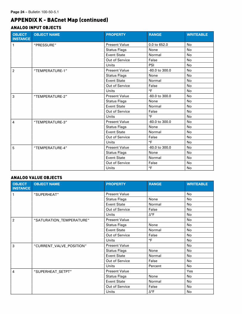
Page 24 – Bulletin 100-50-5.1
APPENDIX K - BACnet Map (continued)ANALOG INPUT OBJECTSOBJECTINSTANCE
OBJECT NAME PROPERTY RANGE WRITEABLE
1 “PRESSURE” Present Value 0.0 to 652.0 NoStatus Flags None NoEvent State Normal NoOut of Service False NoUnits PSI No
2 “TEMPERATURE-1” Present Value -60.0 to 300.0 NoStatus Flags None NoEvent State Normal NoOut of Service False NoUnits °F No
3 “TEMPERATURE-2” Present Value -60.0 to 300.0 NoStatus Flags None NoEvent State Normal NoOut of Service False NoUnits °F No
4 “TEMPERATURE-3” Present Value -60.0 to 300.0 NoStatus Flags None NoEvent State Normal NoOut of Service False NoUnits °F No
5 “TEMPERATURE-4” Present Value -60.0 to 300.0 NoStatus Flags None NoEvent State Normal NoOut of Service False NoUnits °F No
ANALOG VALUE OBJECTSOBJECTINSTANCE
OBJECT NAME PROPERTY RANGE WRITEABLE
1 “SUPERHEAT” Present Value NoStatus Flags None NoEvent State Normal NoOut of Service False NoUnits ∆°F No
2 “SATURATION_TEMPERATURE” Present Value NoStatus Flags None NoEvent State Normal NoOut of Service False NoUnits °F No
3 “CURRENT_VALVE_POSITION” Present Value NoStatus Flags None NoEvent State Normal NoOut of Service False NoUnits Percent No
4 “SUPERHEAT_SETPT” Present Value YesStatus Flags None NoEvent State Normal NoOut of Service False NoUnits ∆°F No
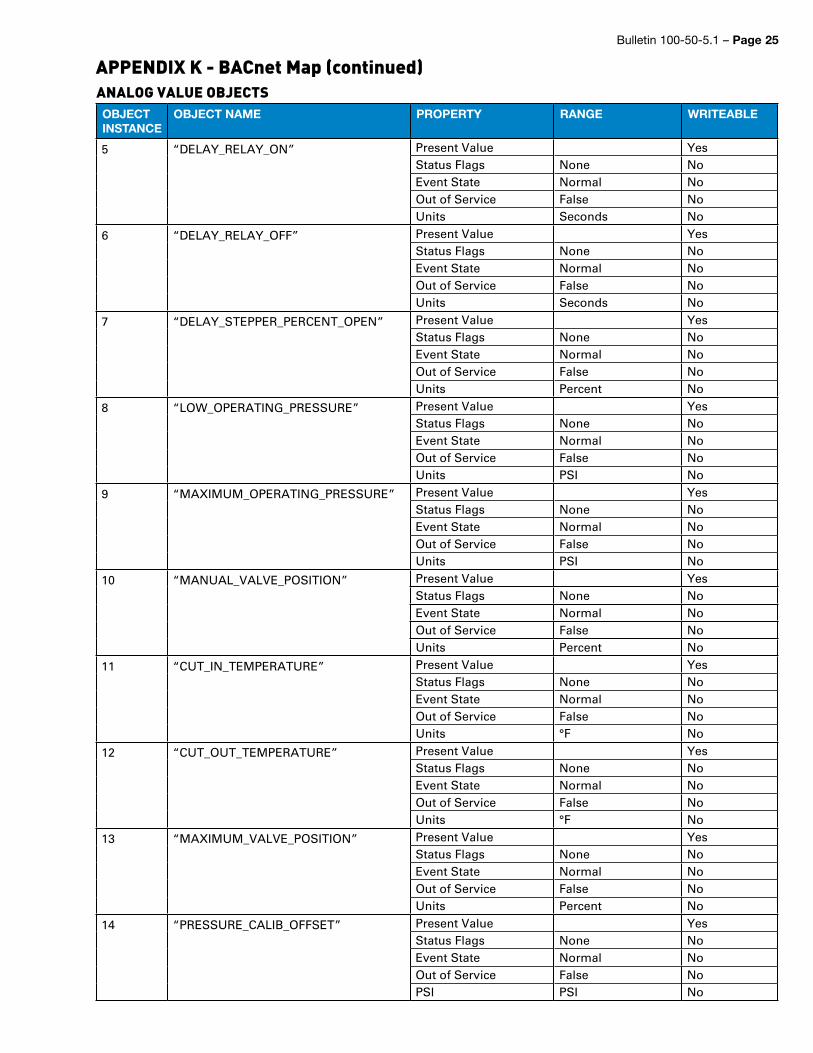
Bulletin 100-50-5.1 – Page 25
APPENDIX K - BACnet Map (continued)ANALOG VALUE OBJECTSOBJECTINSTANCE
OBJECT NAME PROPERTY RANGE WRITEABLE
5 “DELAY_RELAY_ON” Present Value YesStatus Flags None NoEvent State Normal NoOut of Service False NoUnits Seconds No
6 “DELAY_RELAY_OFF” Present Value YesStatus Flags None NoEvent State Normal NoOut of Service False NoUnits Seconds No
7 “DELAY_STEPPER_PERCENT_OPEN” Present Value YesStatus Flags None NoEvent State Normal NoOut of Service False NoUnits Percent No
8 “LOW_OPERATING_PRESSURE” Present Value YesStatus Flags None NoEvent State Normal NoOut of Service False NoUnits PSI No
9 “MAXIMUM_OPERATING_PRESSURE” Present Value YesStatus Flags None NoEvent State Normal NoOut of Service False NoUnits PSI No
10 “MANUAL_VALVE_POSITION” Present Value YesStatus Flags None NoEvent State Normal NoOut of Service False NoUnits Percent No
11 “CUT_IN_TEMPERATURE” Present Value YesStatus Flags None NoEvent State Normal NoOut of Service False NoUnits °F No
12 “CUT_OUT_TEMPERATURE” Present Value YesStatus Flags None NoEvent State Normal NoOut of Service False NoUnits °F No
13 “MAXIMUM_VALVE_POSITION” Present Value YesStatus Flags None NoEvent State Normal NoOut of Service False NoUnits Percent No
14 “PRESSURE_CALIB_OFFSET” Present Value YesStatus Flags None NoEvent State Normal NoOut of Service False NoPSI PSI No
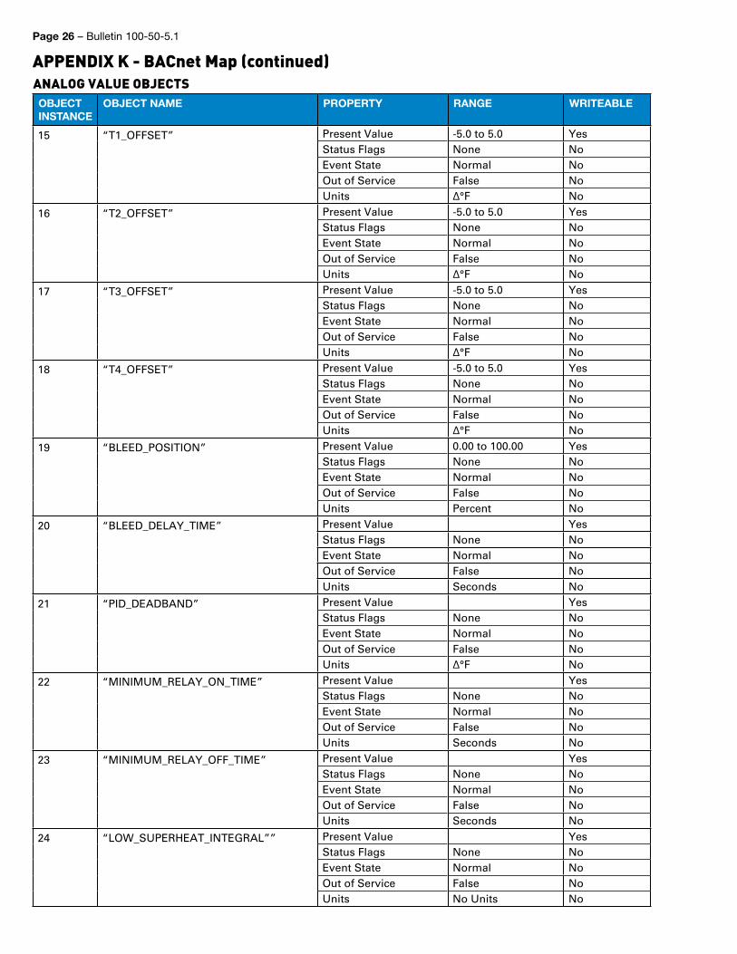
Page 26 – Bulletin 100-50-5.1
APPENDIX K - BACnet Map (continued)ANALOG VALUE OBJECTSOBJECTINSTANCE
OBJECT NAME PROPERTY RANGE WRITEABLE
15 “T1_OFFSET” Present Value -5.0 to 5.0 YesStatus Flags None NoEvent State Normal NoOut of Service False NoUnits ∆°F No
16 “T2_OFFSET” Present Value -5.0 to 5.0 YesStatus Flags None NoEvent State Normal NoOut of Service False NoUnits ∆°F No
17 “T3_OFFSET” Present Value -5.0 to 5.0 YesStatus Flags None NoEvent State Normal NoOut of Service False NoUnits ∆°F No
18 “T4_OFFSET” Present Value -5.0 to 5.0 YesStatus Flags None NoEvent State Normal NoOut of Service False NoUnits ∆°F No
19 “BLEED_POSITION” Present Value 0.00 to 100.00 YesStatus Flags None NoEvent State Normal NoOut of Service False NoUnits Percent No
20 “BLEED_DELAY_TIME” Present Value YesStatus Flags None NoEvent State Normal NoOut of Service False NoUnits Seconds No
21 “PID_DEADBAND” Present Value YesStatus Flags None NoEvent State Normal NoOut of Service False NoUnits ∆°F No
22 “MINIMUM_RELAY_ON_TIME” Present Value YesStatus Flags None NoEvent State Normal NoOut of Service False NoUnits Seconds No
23 “MINIMUM_RELAY_OFF_TIME” Present Value YesStatus Flags None NoEvent State Normal NoOut of Service False NoUnits Seconds No
24 “LOW_SUPERHEAT_INTEGRAL”” Present Value YesStatus Flags None NoEvent State Normal NoOut of Service False NoUnits No Units No
Bulletin 100-50-5.1 – Page 27
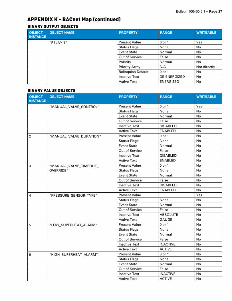
APPENDIX K - BACnet Map (continued)BINARY OUTPUT OBJECTSOBJECTINSTANCE
OBJECT NAME PROPERTY RANGE WRITEABLE
1 “RELAY-1” Present Value 0 or 1 YesStatus Flags None NoEvent State Normal NoOut of Service False NoPolarity Normal NoPriority Array N/A Not directlyRelinquish Default 0 or 1 NoInactive Text DE-ENERGIZED NoActive Text ENERGIZED No
BINARY VALUE OBJECTSOBJECTINSTANCE
OBJECT NAME PROPERTY RANGE WRITEABLE
1 “MANUAL_VALVE_CONTROL” Present Value 0 or 1 YesStatus Flags None NoEvent State Normal NoOut of Service False NoInactive Text DISABLED NoActive Text ENABLED No
2 “MANUAL_VALVE_DURATION” Present Value 0 or 1 NoStatus Flags None NoEvent State Normal NoOut of Service False NoInactive Text DISABLED NoActive Text ENABLED No
3 “MANUAL_VALVE_TIMEOUT_ OVERRIDE”
Present Value 0 or 1 NoStatus Flags None NoEvent State Normal NoOut of Service False NoInactive Text DISABLED NoActive Text ENABLED No
4 “PRESSURE_SENSOR_TYPE” Present Value YesStatus Flags None NoEvent State Normal NoOut of Service False NoInactive Text ABSOLUTE NoActive Text GAUGE No
5 “LOW_SUPERHEAT_ALARM” Present Value 0 or 1 NoStatus Flags None NoEvent State Normal NoOut of Service False NoInactive Text INACTIVE NoActive Text ACTIVE No
6 “HIGH_SUPERHEAT_ALARM” Present Value 0 or 1 NoStatus Flags None NoEvent State Normal NoOut of Service False NoInactive Text INACTIVE NoActive Text ACTIVE No
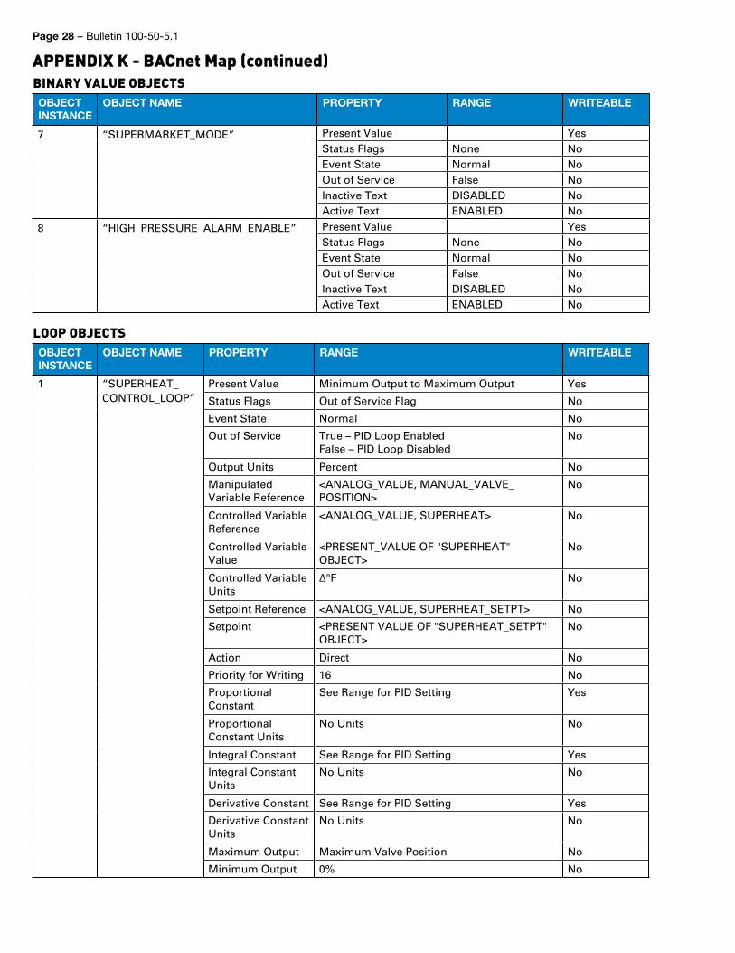
Page 28 – Bulletin 100-50-5.1
APPENDIX K - BACnet Map (continued)BINARY VALUE OBJECTSOBJECTINSTANCE
OBJECT NAME PROPERTY RANGE WRITEABLE
7 “SUPERMARKET_MODE” Present Value YesStatus Flags None NoEvent State Normal NoOut of Service False NoInactive Text DISABLED NoActive Text ENABLED No
8 “HIGH_PRESSURE_ALARM_ENABLE” Present Value YesStatus Flags None NoEvent State Normal NoOut of Service False NoInactive Text DISABLED NoActive Text ENABLED No
LOOP OBJECTSOBJECTINSTANCE
OBJECT NAME PROPERTY RANGE WRITEABLE
1 “SUPERHEAT_CONTROL_LOOP”
Present Value Minimum Output to Maximum Output Yes
Status Flags Out of Service Flag No
Event State Normal No
Out of Service True – PID Loop Enabled False – PID Loop Disabled
No
Output Units Percent No
Manipulated Variable Reference
<ANALOG_VALUE, MANUAL_VALVE_POSITION>
No
Controlled Variable Reference
<ANALOG_VALUE, SUPERHEAT> No
Controlled Variable Value
<PRESENT_VALUE OF "SUPERHEAT" OBJECT>
No
Controlled Variable Units
∆°F No
Setpoint Reference <ANALOG_VALUE, SUPERHEAT_SETPT> No
Setpoint <PRESENT VALUE OF "SUPERHEAT_SETPT" OBJECT>
No
Action Direct No
Priority for Writing 16 No
Proportional Constant
See Range for PID Setting Yes
Proportional Constant Units
No Units No
Integral Constant See Range for PID Setting Yes
Integral Constant Units
No Units No
Derivative Constant See Range for PID Setting Yes
Derivative Constant Units
No Units No
Maximum Output Maximum Valve Position No
Minimum Output 0% No
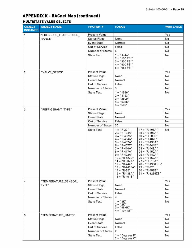
Bulletin 100-50-5.1 – Page 29
APPENDIX K - BACnet Map (continued)MULTISTATE VALUE OBJECTSOBJECTINSTANCE
OBJECT NAME PROPERTY RANGE WRITEABLE
1 “PRESSURE_TRANSDUCER_RANGE”
Present Value YesStatus Flags None NoEvent State Normal NoOut of Service False NoNumber of States 5 No
State Text 1 = “Auto”2 = “150 PSI”3 = “300 PSI”4 = “500 PSI”5 = “652 PSI”
No
2 “VALVE_STEPS” Present Value YesStatus Flags None NoEvent State Normal NoOut of Service False NoNumber of States 5 No
State Text 1 = “1596”2 = “3193”3 = “2500”4 = “6386”5 = “500”
No
3 “REFRIGERANT_TYPE” Present Value YesStatus Flags None NoEvent State Normal NoOut of Service False NoNumber of States 30 No
State Text 1 = “R-22”2 = “R-134A”3 = “R-402A”4 = “R-404A”5 = “R-407A”6 = “R-407C”7 = “R-410A”8 = “R-417A”9 = “R-422A”10 = “R-422D”11 = “R-507A”12 = “R-744”13 = “R-245FA”14 = “R-E5”15 = “R-438A”16 = “R-401B”
17 = “R-408A”18 = “R-508A”19 = “R-508B”20 = “R-407F”21 = “R-438A”22 = “R-444B”23 = “R-448A”24 = “R-450A”25 = “R-449A”26 = “R-452A”27 = “R-513A”28 = “R-1336mzz”29 = “R-32”30 = ”R-452B”31 = “R-1234ZE”
No
4 “TEMPERATURE_SENSOR_TYPE”
Present Value YesStatus Flags None NoEvent State Normal NoOut of Service False NoNumber of States 4 No
State Text 1 = “3K”2 = “2K”3 = “98.6K”4 = “10K-MT”
No
5 “TEMPERATURE_UNITS” Present Value YesStatus Flags None NoEvent State Normal NoOut of Service False NoNumber of States 2 No
State Text 1 = “Degrees F”2 = “Degrees C”
No
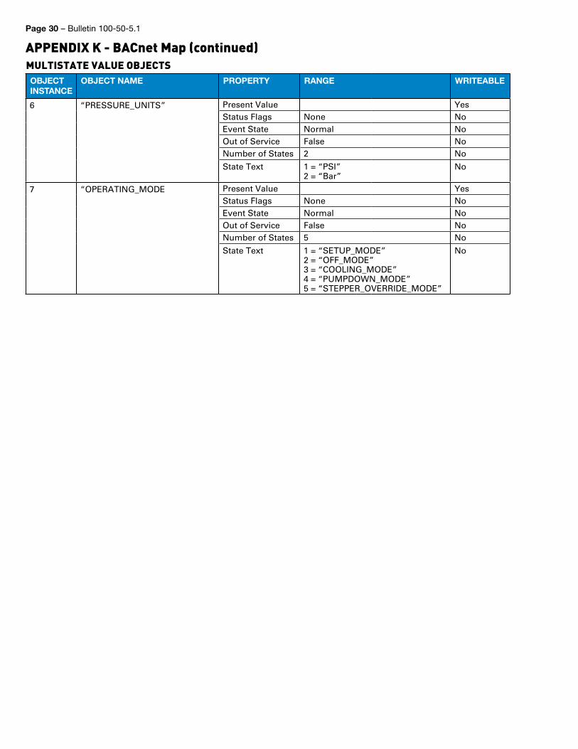
Page 30 – Bulletin 100-50-5.1
APPENDIX K - BACnet Map (continued)MULTISTATE VALUE OBJECTSOBJECTINSTANCE
OBJECT NAME PROPERTY RANGE WRITEABLE
6 “PRESSURE_UNITS” Present Value YesStatus Flags None NoEvent State Normal NoOut of Service False NoNumber of States 2 No
State Text 1 = “PSI”2 = “Bar”
No
7 “OPERATING_MODE Present Value YesStatus Flags None NoEvent State Normal NoOut of Service False NoNumber of States 5 No
State Text 1 = “SETUP_MODE”2 = “OFF_MODE”3 = “COOLING_MODE”4 = “PUMPDOWN_MODE”5 = “STEPPER_OVERRIDE_MODE”
No
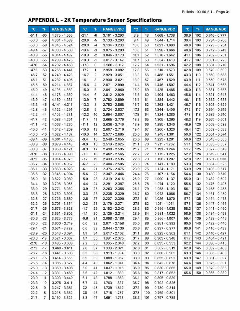
Bulletin 100-50-5.1 – Page 31
APPENDIX L - 2K Temperature Sensor Specifications°C °F RANGE VDC
-51.1 -60 4.375 - 4.555-50.6 -59 4.361 - 4.539-50.0 -58 4.345 - 4.524-49.4 -57 4.330 - 4.508-48.9 -56 4.314 - 4.492-48.3 -55 4.299 - 4.475-47.8 -54 4.282 - 4.458-47.2 -53 4.266 - 4.441-46.7 -52 4.249 - 4.423-46.1 -51 4.232 - 4.406-45.6 -50 4.214 - 4.387-45.0 -49 4.196 - 4.369-44.4 -48 4.178 - 4.350-43.9 -47 4.160 - 4.331-43.3 -46 4.141 - 4.311-42.8 -45 4.122 - 4.291-42.2 -44 4.102 - 4.271-41.7 -43 4.083 - 4.251-41.1 -42 4.063 - 4.230-40.6 -41 4.042 - 4.209-40.0 -40 4.022 - 4.187-39.4 -39 4.001 - 4.165-38.9 -38 3.979 - 4.143-38.3 -37 3.958 - 4.121-37.8 -36 3.936 - 4.098-37.2 -35 3.914 - 4.075-36.7 -34 3.891 - 4.052-36.1 -33 3.868 - 4.028-35.6 -32 3.845 - 4.004-35.0 -31 3.822 - 3.980-34.4 -30 3.798 - 3.955-33.9 -29 3.774 - 3.930-33.3 -28 3.750 - 3.905-32.8 -27 3.726 - 3.880-32.2 -26 3.701 - 3.854-31.7 -25 3.676 - 3.828-31.1 -24 3.651 - 3.802-30.6 -23 3.625 - 3.775-30.0 -22 3.600 - 3.749-29.4 -21 3.574 - 3.722-28.9 -20 3.548 - 3.694-28.3 -19 3.521 - 3.667-27.8 -18 3.495 - 3.639-27.2 -17 3.468 - 3.611-26.7 -16 3.441 - 3.583-26.1 -15 3.414 - 3.555-25.6 -14 3.386 - 3.527-25.0 -13 3.359 - 3.498-24.4 -12 3.331 - 3.469-23.9 -11 3.303 - 3.440-23.3 -10 3.275 - 3.411-22.8 -9 3.247 - 3.381-22.2 -8 3.218 - 3.352-21.7 -7 3.190 - 3.322
°C °F RANGE VDC
-21.1 -6 3.161 - 3.293-20.6 -5 3.133 - 3.263-20.0 -4 3.104 - 3.233-19.4 -3 3.075 - 3.203-18.9 -2 3.046 - 3.173-18.3 -1 3.017 - 3.142-17.8 0 2.988 - 3.112-17.2 1 2.958 - 3.082-16.7 2 2.929 - 3.051-16.1 3 2.900 - 3.021-15.6 4 2.871 - 2.990-15.0 5 2.841 - 2.960-14.4 6 2.812 - 2.929-13.9 7 2.782 - 2.899-13.3 8 2.753 - 2.868-12.8 9 2.724 - 2.837-12.2 10 2.694 - 2.807-11.7 11 2.665 - 2.776-11.1 12 2.636 - 2.746-10.6 13 2.607 - 2.716-10.0 14 2.577 - 2.685-9.4 15 2.548 - 2.655-8.9 16 2.519 - 2.625-8.3 17 2.490 - 2.595-7.8 18 2.462 - 2.565-7.2 19 2.433 - 2.535-6.7 20 2.404 - 2.505-6.1 21 2.376 - 2.475-5.6 22 2.347 - 2.446-5.0 23 2.319 - 2.416-4.4 24 2.291 - 2.387-3.9 25 2.263 - 2.358-3.3 26 2.235 - 2.329-2.8 27 2.207 - 2.300-2.2 28 2.179 - 2.271-1.7 29 2.152 - 2.242-1.1 30 2.125 - 2.214-0.6 31 2.098 - 2.1860.0 32 2.071 - 2.1580.6 33 2.044 - 2.1301.1 34 2.017 - 2.1021.7 35 1.991 - 2.0752.2 36 1.965 - 2.0482.8 37 1.939 - 2.0213.3 38 1.913 - 1.9943.9 39 1.888 - 1.9674.4 40 1.862 - 1.9415.0 41 1.837 - 1.9155.6 42 1.812 - 1.8896.1 43 1.788 - 1.8636.7 44 1.763 - 1.8377.2 45 1.739 - 1.8127.8 46 1.715 - 1.7878.3 47 1.691 - 1.763
°C °F RANGE VDC
8.9 48 1.668 - 1.7389.4 49 1.644 - 1.71410.0 50 1.621 - 1.69010.6 51 1.598 - 1.66611.1 52 1.576 - 1.64211.7 53 1.554 - 1.61912.2 54 1.531 - 1.59612.8 55 1.510 - 1.57313.3 56 1.488 - 1.55113.9 57 1.467 - 1.52914.4 58 1.446 - 1.50715.0 59 1.425 - 1.48515.6 60 1.404 - 1.46316.1 61 1.384 - 1.44216.7 62 1.363 - 1.42117.2 63 1.344 - 1.40017.8 64 1.324 - 1.38018.3 65 1.305 - 1.36018.9 66 1.285 - 1.34019.4 67 1.266 - 1.32020.0 68 1.248 - 1.30120.6 69 1.229 - 1.28121.1 70 1.211 - 1.26221.7 71 1.193 - 1.24422.2 72 1.175 - 1.22522.8 73 1.158 - 1.20723.3 74 1.141 - 1.18923.9 75 1.124 - 1.17124.4 76 1.107 - 1.15425.0 77 1.090 - 1.13725.6 78 1.074 - 1.12026.1 79 1.058 - 1.10326.7 80 1.042 - 1.08627.2 81 1.026 - 1.07027.8 82 1.011 - 1.05428.3 83 0.996 - 1.03828.9 84 0.981 - 1.02229.4 85 0.966 - 1.00730.0 86 0.951 - 0.99230.6 87 0.937 - 0.97731.1 88 0.923 - 0.96231.7 89 0.909 - 0.94832.2 90 0.895 - 0.93332.8 91 0.882 - 0.91933.3 92 0.868 - 0.90533.9 93 0.855 - 0.89234.4 94 0.842 - 0.87835.0 95 0.830 - 0.86535.6 96 0.817 - 0.85236.1 97 0.805 - 0.83936.7 98 0.792 - 0.82637.2 99 0.780 - 0.81437.8 100 0.769 - 0.80138.3 101 0.757 - 0.789
°C °F RANGE VDC
38.9 102 0.746 - 0.77739.4 103 0.734 - 0.76640.0 104 0.723 - 0.75440.6 105 0.712 - 0.74341.1 106 0.702 - 0.73141.7 107 0.691 - 0.72042.2 108 0.681 - 0.71042.8 109 0.670 - 0.69943.3 110 0.660 - 0.68843.9 111 0.650 - 0.67844.4 112 0.641 - 0.66845.0 113 0.631 - 0.65845.6 114 0.621 - 0.64846.1 115 0.612 - 0.63846.7 116 0.603 - 0.62947.2 117 0.594 - 0.61947.8 118 0.585 - 0.61048.3 119 0.576 - 0.60148.9 120 0.568 - 0.59249.4 121 0.559 - 0.58350.0 122 0.551 - 0.57450.6 123 0.543 - 0.56651.1 124 0.535 - 0.55751.7 125 0.527 - 0.54952.2 126 0.519 - 0.54152.8 127 0.511 - 0.53353.3 128 0.504 - 0.52553.9 129 0.496 - 0.51754.4 130 0.489 - 0.51055.0 131 0.482 - 0.50255.6 132 0.475 - 0.49556.1 133 0.468 - 0.48856.7 134 0.461 - 0.48057.2 135 0.454 - 0.47357.8 136 0.447 - 0.46658.3 137 0.441 - 0.46058.9 138 0.434 - 0.45359.4 139 0.428 - 0.44660.0 140 0.422 - 0.44060.6 141 0.416 - 0.43361.1 142 0.410 - 0.42761.7 143 0.404 - 0.42162.2 144 0.398 - 0.41562.8 145 0.392 - 0.40963.3 146 0.386 - 0.40363.9 147 0.381 - 0.39764.4 148 0.375 - 0.39165.0 149 0.370 - 0.38665.6 150 0.365 - 0.380
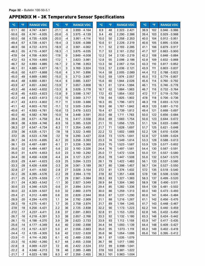
Page 32 – Bulletin 100-50-5.1
APPENDIX M - 3K Temperature Sensor Specifications°C °F RANGE VDC
-51.1 -60 4.747 - 4.941-50.6 -59 4.741 - 4.935-50.0 -58 4.735 - 4.928-49.4 -57 4.728 - 4.921-48.9 -56 4.722 - 4.915-48.3 -55 4.715 - 4.907-47.8 -54 4.708 - 4.900-47.2 -53 4.700 - 4.893-46.7 -52 4.693 - 4.885-46.1 -51 4.685 - 4.877-45.6 -50 4.677 - 4.868-45.0 -49 4.669 - 4.860-44.4 -48 4.660 - 4.851-43.9 -47 4.651 - 4.842-43.3 -46 4.642 - 4.832-42.8 -45 4.633 - 4.823-42.2 -44 4.623 - 4.813-41.7 -43 4.613 - 4.802-41.1 -42 4.603 - 4.792-40.6 -41 4.593 - 4.781-40.0 -40 4.582 - 4.769-39.4 -39 4.571 - 4.758-38.9 -38 4.559 - 4.746-38.3 -37 4.547 - 4.734-37.8 -36 4.535 - 4.721-37.2 -35 4.523 - 4.708-36.7 -34 4.510 - 4.695-36.1 -33 4.497 - 4.681-35.6 -32 4.484 - 4.667-35.0 -31 4.470 - 4.653-34.4 -30 4.456 - 4.638-33.9 -29 4.441 - 4.623-33.3 -28 4.426 - 4.608-32.8 -27 4.411 - 4.592-32.2 -26 4.395 - 4.576-31.7 -25 4.379 - 4.559-31.1 -24 4.363 - 4.542-30.6 -23 4.346 - 4.525-30.0 -22 4.329 - 4.507-29.4 -21 4.312 - 4.489-28.9 -20 4.294 - 4.470-28.3 -19 4.275 - 4.451-27.8 -18 4.256 - 4.431-27.2 -17 4.237 - 4.411-26.7 -16 4.218 - 4.391-26.1 -15 4.198 - 4.370-25.6 -14 4.177 - 4.349-25.0 -13 4.157 - 4.327-24.4 -12 4.135 - 4.305-23.9 -11 4.114 - 4.283-23.3 -10 4.092 - 4.260-22.8 -9 4.069 - 4.237-22.2 -8 4.046 - 4.213-21.7 -7 4.023 - 4.189
°C °F RANGE VDC
-21.1 -6 3.999 - 4.164-20.6 -5 3.975 - 4.139-20.0 -4 3.951 - 4.114-19.4 -3 3.926 - 4.088-18.9 -2 3.901 - 4.062-18.3 -1 3.875 - 4.035-17.8 0 3.849 - 4.008-17.2 1 3.823 - 3.981-16.7 2 3.796 - 3.953-16.1 3 3.769 - 3.924-15.6 4 3.741 - 3.896-15.0 5 3.713 - 3.867-14.4 6 3.685 - 3.837-13.9 7 3.657 - 3.808-13.3 8 3.628 - 3.778-12.8 9 3.598 - 3.747-12.2 10 3.569 - 3.717-11.7 11 3.539 - 3.686-11.1 12 3.509 - 3.654-10.6 13 3.478 - 3.623-10.0 14 3.448 - 3.591-9.4 15 3.417 - 3.558-8.9 16 3.385 - 3.526-8.3 17 3.354 - 3.493-7.8 18 3.322 - 3.460-7.2 19 3.290 - 3.427-6.7 20 3.258 - 3.393-6.1 21 3.226 - 3.360-5.6 22 3.193 - 3.326-5.0 23 3.160 - 3.292-4.4 24 3.127 - 3.257-3.9 25 3.094 - 3.223-3.3 26 3.061 - 3.189-2.8 27 3.028 - 3.154-2.2 28 2.994 - 3.119-1.7 29 2.961 - 3.084-1.1 30 2.927 - 3.049-0.6 31 2.894 - 3.0140.0 32 2.860 - 2.9790.6 33 2.826 - 2.9441.1 34 2.792 - 2.9091.7 35 2.758 - 2.8742.2 36 2.725 - 2.8382.8 37 2.691 - 2.8033.3 38 2.657 - 2.7683.9 39 2.623 - 2.7334.4 40 2.590 - 2.6985.0 41 2.556 - 2.6635.6 42 2.522 - 2.6286.1 43 2.489 - 2.5936.7 44 2.455 - 2.5587.2 45 2.422 - 2.5247.8 46 2.389 - 2.4898.3 47 2.356 - 2.455
°C °F RANGE VDC
8.9 48 2.323 - 2.4219.4 49 2.290 - 2.38610.0 50 2.258 - 2.35310.6 51 2.226 - 2.31911.1 52 2.193 - 2.28511.7 53 2.161 - 2.25212.2 54 2.130 - 2.21912.8 55 2.098 - 2.18613.3 56 2.067 - 2.15413.9 57 2.036 - 2.12114.4 58 2.005 - 2.08915.0 59 1.974 - 2.05715.6 60 1.944 - 2.02616.1 61 1.914 - 1.99416.7 62 1.884 - 1.96317.2 63 1.854 - 1.93217.8 64 1.825 - 1.90218.3 65 1.796 - 1.87218.9 66 1.767 - 1.84219.4 67 1.739 - 1.81220.0 68 1.711 - 1.78320.6 69 1.683 - 1.75421.1 70 1.656 - 1.72521.7 71 1.628 - 1.69722.2 72 1.602 - 1.66922.8 73 1.575 - 1.64123.3 74 1.549 - 1.61423.9 75 1.523 - 1.58724.4 76 1.497 - 1.56125.0 77 1.472 - 1.53425.6 78 1.447 - 1.50826.1 79 1.422 - 1.48326.7 80 1.398 - 1.45727.2 81 1.374 - 1.43227.8 82 1.351 - 1.40828.3 83 1.327 - 1.38328.9 84 1.304 - 1.36029.4 85 1.282 - 1.33630.0 86 1.259 - 1.31330.6 87 1.237 - 1.29031.1 88 1.216 - 1.26731.7 89 1.194 - 1.24532.2 90 1.173 - 1.22332.8 91 1.153 - 1.20233.3 92 1.132 - 1.18033.9 93 1.112 - 1.15934.4 94 1.093 - 1.13935.0 95 1.073 - 1.11935.6 96 1.054 - 1.09936.1 97 1.035 - 1.07936.7 98 1.017 - 1.06037.2 99 0.998 - 1.04137.8 100 0.981 - 1.02238.3 101 0.963 - 1.004
°C °F RANGE VDC
38.9 102 0.946 - 0.98639.4 103 0.929 - 0.96840.0 104 0.912 - 0.95140.6 105 0.895 - 0.93441.1 106 0.879 - 0.91741.7 107 0.863 - 0.90042.2 108 0.848 - 0.88442.8 109 0.832 - 0.86843.3 110 0.817 - 0.85243.9 111 0.803 - 0.83744.4 112 0.788 - 0.82245.0 113 0.774 - 0.80745.6 114 0.760 - 0.79246.1 115 0.746 - 0.77846.7 116 0.732 - 0.76447.2 117 0.719 - 0.75047.8 118 0.706 - 0.73648.3 119 0.693 - 0.72348.9 120 0.681 - 0.71049.4 121 0.668 - 0.69750.0 122 0.656 - 0.68450.6 123 0.644 - 0.67251.1 124 0.633 - 0.66051.7 125 0.621 - 0.64852.2 126 0.610 - 0.63652.8 127 0.599 - 0.62453.3 128 0.588 - 0.61353.9 129 0.577 - 0.60254.4 130 0.567 - 0.59155.0 131 0.557 - 0.58055.6 132 0.547 - 0.57056.1 133 0.537 - 0.56056.7 134 0.527 - 0.55057.2 135 0.518 - 0.54057.8 136 0.508 - 0.53058.3 137 0.499 - 0.52058.9 138 0.490 - 0.51159.4 139 0.481 - 0.50260.0 140 0.473 - 0.49360.6 141 0.464 - 0.48461.1 142 0.456 - 0.47561.7 143 0.448 - 0.46762.2 144 0.440 - 0.45962.8 145 0.432 - 0.45063.3 146 0.424 - 0.44263.9 147 0.417 - 0.43564.4 148 0.409 - 0.42765.0 149 0.402 - 0.41965.6 150 0.395 - 0.412
Bulletin 100-50-5.1 – Page 33
OFFER OF SALEThe goods, services or work (referred to as the “Products”) offered by Parker-Hannifin Corporation, its subsidiaries, groups, divisions, and authorized distributors (“Seller”) are offered for sale at prices indicated in the offer, or as may be established by Seller. The offer to sell the Products and acceptance of Seller’s offer by any customer (“Buyer”) is contingent upon, and will be governed by all of the terms and conditions contained in this Offer of Sale. Buyer’s order for any Products specified in Buyer’s purchase document or Seller’s offer, proposal or quote (“Quote”) attached to the purchase order, when communicated to Seller verbally, or in writing, shall constitute acceptance of this offer.
1. Terms and Conditions. Seller’s willingness to offer Products for sale or accept an order for Products is subject to the terms and conditions contained in this Offer of Sale or any newer version of the same, published by Seller electronically at www.parker.com/saleterms/. Seller objects to any contrary or additional terms or conditions of Buyer’s order or any other docu-ment or other communication issued by Buyer.2. Price; Payment. Prices stated on Seller’s Quote are valid for thirty (30) days, except as explicitly otherwise stated therein, and do not include any sales, use, or other taxes or duties unless specifically stated. Seller reserves the right to modify prices to adjust for any raw material price fluctuations. Unless otherwise specified by Seller, all prices are F.C.A. Seller’s facility (INCO-TERMS 2010). Payment is subject to credit approval and payment for all purchases is due thirty (30) days from the date of invoice (or such date as may be speci-fied by Seller’s Credit Department). Unpaid invoices beyond the specified payment date incur interest at the rate of 1.5% per month or the maximum allowable rate under applicable law.3. Shipment; Delivery; Title and Risk of Loss. All delivery dates are approximate. Seller is not respon-sible for damages resulting from any delay. Regardless of the manner of shipment, delivery occurs and title and risk of loss or damage pass to Buyer, upon placement of the Products with the shipment carrier at Seller’s facility. Unless otherwise stated, Seller may exercise its judgment in choosing the carrier and means of delivery. No deferment of shipment at Buyers’ request beyond the respective dates indicated will be made except on terms that will indemnify, defend and hold Seller harm-less against all loss and additional expense. Buyer shall be responsible for any additional shipping charges incurred by Seller due to Buyer’s acts or omissions.4. Warranty. Seller warrants that the Products sold hereunder shall be free from defects in material or workmanship for a period of twelve (12) months from the date of delivery or 2,000 hours of normal use, whichever occurs first. All prices are based upon the exclusive limited warranty stated above, and upon the following disclaimer: DISCLAIMER OF WARRANTY: THIS WARRANTY IS THE SOLE AND ENTIRE WAR-RANTY PERTAINING TO PRODUCTS PROVIDED. SELLER DISCLAIMS ALL OTHER WARRANTIES, EXPRESS AND IMPLIED, INCLUDING DESIGN, MERCHANTABILITY AND FITNESS FOR A PARTICU-LAR PURPOSE.5. Claims; Commencement of Actions. Buyer shall promptly inspect all Products upon receipt. No claims for shortages will be allowed unless reported to the Seller within ten (10) days of delivery. No other claims against Seller will be allowed unless asserted in writing within thirty (30) days after delivery. Buyer shall notify Seller of any alleged breach of warranty within thirty (30) days after the date the defect is or should have been discovered by Buyer. Any claim or action against Seller based upon breach of contract or any other theory, including tort, negligence, or otherwise must be commenced within twelve (12) months from the date of the alleged breach or other alleged event, without regard to the date of discovery.6. LIMITATION OF LIABILITY. IN THE EVENT OF A BREACH OF WARRANTY, SELLER WILL, AT ITS OPTION, REPAIR OR REPLACE A DEFECTIVE PROD-UCT, OR REFUND THE PURCHASE PRICE WITHIN A REASONABLE PERIOD OF TIME. IN NO EVENT IS SELLER LIABLE FOR ANY SPECIAL, INDIRECT, INCIDENTAL OR CONSEQUENTIAL DAMAGES ARISING OUT OF, OR AS THE RESULT OF, THE SALE, DELIVERY, NON-DELIVERY, SERVICING, USE OR LOSS OF USE OF THE PRODUCTS OR ANY PART THEREOF, OR FOR ANY CHARGES OR EXPENSES OF ANY NATURE INCURRED WITHOUT SELLER’S WRITTEN CONSENT, WHETHER BASED IN CONTRACT, TORT OR OTHER LEGAL THEORY. IN NO EVENT SHALL SELLER’S LIABILITY UNDER ANY CLAIM MADE BY BUYER EXCEED THE PUR-CHASE PRICE OF THE PRODUCTS.7. User Responsibility. The user, through its own analysis and testing, is solely responsible for making the final selection of the system and Product and assuring that all performance, endurance, maintenance, safety and warning requirements of the application are met. The user must analyze all aspects of the applica-
tion and follow applicable industry standards and Prod-uct information. If Seller provides Product or system options based upon data or specifications provided by the user, the user is responsible for determining that such data and specifications are suitable and sufficient for all applications and reasonably foreseeable uses of the Products or systems.8. Loss to Buyer’s Property. Any designs, tools, patterns, materials, drawings, confidential information or equipment furnished by Buyer or any other items which become Buyer’s property, will be considered obsolete and may be destroyed by Seller after two (2) consecutive years have elapsed without Buyer ordering the items manufactured using such property. Seller shall not be responsible for any loss or damage to such property while it is in Seller’s possession or control.9. Special Tooling. A tooling charge may be imposed for any special tooling, including without limita-tion, dies, fixtures, molds and patterns, acquired to manufacture Products. Such special tooling shall be and remain Seller’s property notwithstanding payment of any charges by Buyer. In no event will Buyer acquire any interest in apparatus belonging to Seller which is utilized in the manufacture of the Products, even if such apparatus has been specially converted or adapted for such manufacture and notwithstanding any charges paid by Buyer. Unless otherwise agreed, Seller has the right to alter, discard or otherwise dispose of any special tooling or other property in its sole discretion at any time.10. Buyer’s Obligation; Rights of Seller. To secure payment of all sums due or otherwise, Seller retains a security interest in all Products delivered to Buyer and this agreement is deemed to be a Security Agreement under the Uniform Commercial Code. Buyer authorizes Seller as its attorney to execute and file on Buyer’s behalf all documents Seller deems necessary to perfect its security interest. 11. Improper Use and Indemnity. Buyer shall indemnify, defend, and hold Seller harmless from any losses, claims, liabilities, damages, lawsuits, judgments and costs (including attorney fees and defense costs), whether for personal injury, property damage, patent, trademark or copyright infringement or any other claim, brought by or incurred by Buyer, Buyer’s employees, or any other person, arising out of: (a) improper selec-tion, application, design, specification or other misuse of Products purchased by Buyer from Seller; (b) any act or omission, negligent or otherwise, of Buyer; (c) Seller’s use of patterns, plans, drawings, or specifica-tions furnished by Buyer to manufacture Products; or (d) Buyer’s failure to comply with these terms and conditions. Seller shall not indemnify Buyer under any circumstance except as otherwise provided.12. Cancellations and Changes. Buyer may not can-cel or modify or cancel any order for any reason, except with Seller’s written consent and upon terms that will indemnify, defend and hold Seller harmless against all direct, incidental and consequential loss or damage. Seller may change Product features, specifications, designs and availability.13. Limitation on Assignment. Buyer may not assign its rights or obligations under this agreement without the prior written consent of Seller.14. Force Majeure. Seller does not assume the risk and is not liable for delay or failure to perform any of Seller’s obligations by reason of events or circum-stances beyond its reasonable control (hereinafter “Events of Force Majeure”). Events of Force Majeure shall include without limitation: accidents, strikes or labor disputes, acts of any government or government agency, acts of nature, delays or failures in delivery from carriers or suppliers, shortages of materials, or any other cause beyond Seller’s reasonable control. 15. Waiver and Severability. Failure to enforce any provision of this agreement will not invalidate that provi-sion; nor will any such failure prejudice Seller’s right to enforce that provision in the future. Invalidation of any provision of this agreement by legislation or other rule of law shall not invalidate any other provision herein. The remaining provisions of this agreement will remain in full force and effect.16. Termination. Seller may terminate this agreement for any reason and at any time by giving Buyer thirty (30) days prior written notice. Seller may immediately terminate this agreement, in writing, if Buyer: (a)
breaches any provision of this agreement (b) appoints a trustee, receiver or custodian for all or any part of Buyer’s property (c) files a petition for relief in bank-ruptcy on its own behalf, or one if filed by a third party (d) makes an assignment for the benefit of creditors; or (e) dissolves its business or liquidates all or a majority of its assets.17. Governing Law. This agreement and the sale and delivery of all Products are deemed to have taken place in, and shall be governed and construed in accordance with, the laws of the State of Ohio, as applicable to contracts executed and wholly performed therein and without regard to conflicts of laws principles. Buyer irrevocably agrees and consents to the exclusive juris-diction and venue of the courts of Cuyahoga County, Ohio with respect to any dispute, controversy or claim arising out of or relating to this agreement. 18. Indemnity for Infringement of Intellectual Property Rights. Seller is not liable for infringement of any patents, trademarks, copyrights, trade dress, trade secrets or similar rights except as provided in this Section. Seller will defend and indemnify Buyer against allegations of infringement of U.S. patents, U.S. trademarks, copyrights, trade dress and trade secrets (“Intellectual Property Rights”). Seller will defend at its expense and will pay the cost of any settlement or damages awarded in an action brought against Buyer based on an allegation that a Product sold pursuant to this agreement infringes the Intellectual Property Rights of a third party. Seller’s obligation to defend and indemnify Buyer is contingent on Buyer notifying Seller within ten (10) days after Buyer becomes aware of such allegations of infringement, and Seller having sole control over the defense of any allegations or actions including all negotiations for settlement or compromise. If a Product is subject to a claim that it infringes the Intellectual Property Rights of a third party, Seller may, at its sole expense and option, procure for Buyer the right to continue using the Product, replace or modify the Product so as to make it noninfringing, or offer to accept return of the Product and refund the purchase price less a reasonable allowance for depreciation. Notwithstanding the foregoing, Seller is not liable for claims of infringement based on information provided by Buyer, or directed to Products delivered hereunder for which the designs are specified in whole or part by Buyer, or infringements resulting from the modification, combination or use in a system of any Product sold hereunder. The foregoing provisions of this Section constitute Seller’s sole and exclusive liability and Buyer’s sole and exclusive remedy for infringement of Intellectual Property Rights.19. Entire Agreement. This agreement contains the entire agreement between the Buyer and Seller and constitutes the final, complete and exclusive expres-sion of the terms of sale. All prior or contemporane-ous written or oral agreements or negotiations with respect to the subject matter are herein merged. The terms contained herein may not be modified unless in writing and signed by an authorized representative of Seller.20. Compliance with Laws. Buyer agrees to comply with all applicable laws, regulations, and industry and professional standards of care, including those of the United Kingdom, the United States of America, and the country or countries in which Buyer may operate, including without limitation the U. K. Bribery Act, the U.S. Foreign Corrupt Practices Act (“FCPA”), the U.S. Anti-Kickback Act (“Anti-Kickback Act”) and the U.S. Food Drug and Cosmetic Act (“FDCA”),each as currently amended, and the rules and regulations promulgated by the U.S. Food and Drug Administration (“FDA”), and agrees to indemnify and hold harmless Seller from the consequences of any violation of such provisions by Buyer, its employees or agents. Buyer acknowledges that it is familiar with the provisions of the U. K. Bribery Act, the FCPA, the FDA, and the Anti-Kickback Act, and certifies that Buyer will adhere to the requirements thereof. In particular, Buyer represents and agrees that Buyer will not make any payment or give anything of value, directly or indirectly to any gov-ernmental official, any foreign political party or official thereof, any candidate for foreign political office, or any commercial entity or person, for the purpose of influ-encing such person to purchase Products or otherwise benefit the business of Seller.


Parker Hannifin CorporationSporlan Division206 Lange Drive, Washington, MO 63090 USA phone 636 239 1111 fax 636 239 9130 www.sporlan.com
Bulletin 100-50-5.1 / 82016 © 2016 Parker Hannifin Corporation.