Embed Size (px)
Citation preview

ATTACHMENT 3: EMF DATA FOR PROJECT ALTERNATIVES


Magnetic Field Calculations Provided in Response to
CPUC Data Request #10 for the Proposed Sycamore to
Peñasquitos 230 kV Transmission Line Project
Revised Version per CPUC Data Request #19
Project Engineer: Willie Thomas, Transmission Engineering & Design Manager
Project Designer: Flynn Ortiz, Transmission Engineering & Design Advisor
Work Order No.: WO 13128
In-Service Date: May 2017
Power and Transmission Lines:
TL 23001, TL 23004, TL 23051, TL230XX, TL13804, TL13820, TL13811, TL 675, TL 6906, Tl 6920
Central File No.: ELA 140.B.XX
Prepared by: J. Turman
Date: 12/29/2015


i
Table of Contents
I. INTRODUCTION................................................................................................................. 2
II. MAGNETIC FIELD MANAGEMENT DESIGN GUIDELINES ................................... 2
III. MAGNETIC FIELD MANAGEMENT METHODOLOGY ........................................... 3
IV. ORIGINAL PROPOSED PROJECT SCOPE ................................................................... 4
V. PROJECT DESCRIPTIONS FOR THE PROPOSED ALTERNATIVE ROUTES ..... 4
ALTERNATIVE 1: MERCY ROAD UNDERGROUND ALTERNATIVE ................................................. 4
ALTERNATIVE 2: STONEBRIDGE – MIRA MESA COMBINED UNDERGROUND AND OVERHEAD..... 5
ALTERNATIVE 3: POMERADO – MIRAMAR AREA NORTH COMBINED UNDERGROUND AND
OVERHEAD ................................................................................................................... 5
ALTERNATIVE 4: POMERADO – MIRAMAR COMBINED UNDERGROUND AND OVERHEAD ............ 5
ALTERNATIVE 5: PARTIAL SEGMENT D 69 KV UNDERGROUND .................................................. 6
VI. SUMMARY OF CALCULATED MAGNETIC FIELD VALUES .................................. 7
TABLE 1: EASTERLY OVERHEAD, ALTERNATIVES 1-5 ................................................................. 7
TABLE 2: 230 KV UNDERGROUND, ALTERNATIVES 1-4 .............................................................. 7
TABLE 3A: SEGMENT D VALUES IN ORIGINAL FMP ................................................................... 8
TABLE 3B: WESTERLY OVERHEAD, ALTERNATIVE 1 .................................................................. 8
TABLE 4: WESTERLY OVERHEAD, ALTERNATIVES 2-4 ................................................................ 8
TABLE 5: WESTERLY OVERHEAD, ALTERNATIVE 5 – WITH 69 KVAND WITHOUT 69 KV ............. 9
TABLE 6: WESTERLY 69 KV UNDERGROUND, ALTERNATIVE 5 ................................................... 9
MAPS OF THE FIVE PROPOSED ALTERNATIVE ROUTES FOR THE PROJECT .... 10
2
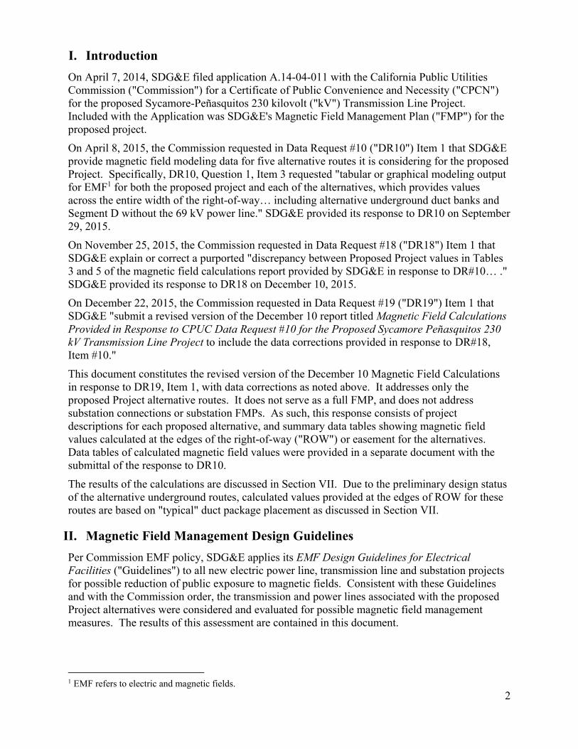
I. Introduction
On April 7, 2014, SDG&E filed application A.14-04-011 with the California Public Utilities Commission ("Commission") for a Certificate of Public Convenience and Necessity ("CPCN") for the proposed Sycamore-Peñasquitos 230 kilovolt ("kV") Transmission Line Project. Included with the Application was SDG&E's Magnetic Field Management Plan ("FMP") for the proposed project.
On April 8, 2015, the Commission requested in Data Request #10 ("DR10") Item 1 that SDG&E provide magnetic field modeling data for five alternative routes it is considering for the proposed Project. Specifically, DR10, Question 1, Item 3 requested "tabular or graphical modeling output for EMF1 for both the proposed project and each of the alternatives, which provides values across the entire width of the right-of-way… including alternative underground duct banks and Segment D without the 69 kV power line." SDG&E provided its response to DR10 on September 29, 2015.
On November 25, 2015, the Commission requested in Data Request #18 ("DR18") Item 1 that SDG&E explain or correct a purported "discrepancy between Proposed Project values in Tables 3 and 5 of the magnetic field calculations report provided by SDG&E in response to DR#10… ." SDG&E provided its response to DR18 on December 10, 2015.
On December 22, 2015, the Commission requested in Data Request #19 ("DR19") Item 1 that SDG&E "submit a revised version of the December 10 report titled Magnetic Field Calculations Provided in Response to CPUC Data Request #10 for the Proposed Sycamore Peñasquitos 230 kV Transmission Line Project to include the data corrections provided in response to DR#18, Item #10."
This document constitutes the revised version of the December 10 Magnetic Field Calculations in response to DR19, Item 1, with data corrections as noted above. It addresses only the proposed Project alternative routes. It does not serve as a full FMP, and does not address substation connections or substation FMPs. As such, this response consists of project descriptions for each proposed alternative, and summary data tables showing magnetic field values calculated at the edges of the right-of-way ("ROW") or easement for the alternatives. Data tables of calculated magnetic field values were provided in a separate document with the submittal of the response to DR10.
The results of the calculations are discussed in Section VII. Due to the preliminary design status of the alternative underground routes, calculated values provided at the edges of ROW for these routes are based on "typical" duct package placement as discussed in Section VII.
II. Magnetic Field Management Design Guidelines
Per Commission EMF policy, SDG&E applies its EMF Design Guidelines for Electrical Facilities ("Guidelines") to all new electric power line, transmission line and substation projects for possible reduction of public exposure to magnetic fields. Consistent with these Guidelines and with the Commission order, the transmission and power lines associated with the proposed Project alternatives were considered and evaluated for possible magnetic field management measures. The results of this assessment are contained in this document.
1 EMF refers to electric and magnetic fields.
3
Per the Guidelines,2 magnetic field assessment and calculations referenced in this document do not include electric distribution lines.
This document deals solely with magnetic fields. Moreover, reducing the magnetic field strength is but one of many factors to be considered in planning and designing a transmission system, along with other issues such as safety, environmental concerns, reliability, insulation and electrical clearance requirements, aesthetics, cost, operations and maintenance.
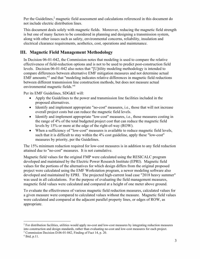
III. Magnetic Field Management Methodology
In Decision 06-01-042, the Commission notes that modeling is used to compare the relative effectiveness of field-reduction options and is not to be used to predict post-construction field levels. Decision 06-01-042 also notes that "[U]tility modeling methodology is intended to compare differences between alternative EMF mitigation measures and not determine actual EMF amounts;"3 and that "modeling indicates relative differences in magnetic field reductions between different transmission line construction methods, but does not measure actual environmental magnetic fields."4
Per its EMF Guidelines, SDG&E will: Apply the Guidelines to the power and transmission line facilities included in the
proposed alternatives. Identify and implement appropriate "no-cost" measures, i.e., those that will not increase
overall project costs but can reduce the magnetic field levels. Identify and implement appropriate "low-cost" measures, i.e., those measures costing in
the range of 4% of the total budgeted project cost that can reduce the magnetic field levels by 15% or more at the edge of the right-of-way (ROW).
When a sufficiency of "low-cost" measures is available to reduce magnetic field levels, such that it is difficult to stay within the 4% cost guideline, apply these "low-cost" measures by priority, per the Guidelines.
The 15% minimum reduction required for low-cost measures is in addition to any field reduction attained due to "no-cost" measures. It is not cumulative.
Magnetic field values for the original FMP were calculated using the RESICALC program developed and maintained by the Electric Power Research Institute (EPRI). Magnetic field values for the portions of the alternatives for which design differs from the original proposed project were calculated using the EMF Workstation program, a newer modeling software also developed and maintained by EPRI. The projected high-current load case "2018 heavy summer" was used in all calculations. For the purpose of evaluating the field management measures, magnetic field values were calculated and compared at a height of one meter above ground.
To evaluate the effectiveness of various magnetic field reduction measures, calculated values for a given measure were compared to calculated values without the measure. Magnetic field values were calculated and compared at the adjacent parallel property lines, or edges of ROW, as appropriate.
2 For distribution facilities, utilities would apply no-cost and low-cost measures by integrating reduction measures into construction and design standards, rather than evaluating no-cost and low-cost measures for each project. 3 Commission Decision D.06-01-042, Finding of Fact 14, p. 20. 4 Ibid, p.11.
4
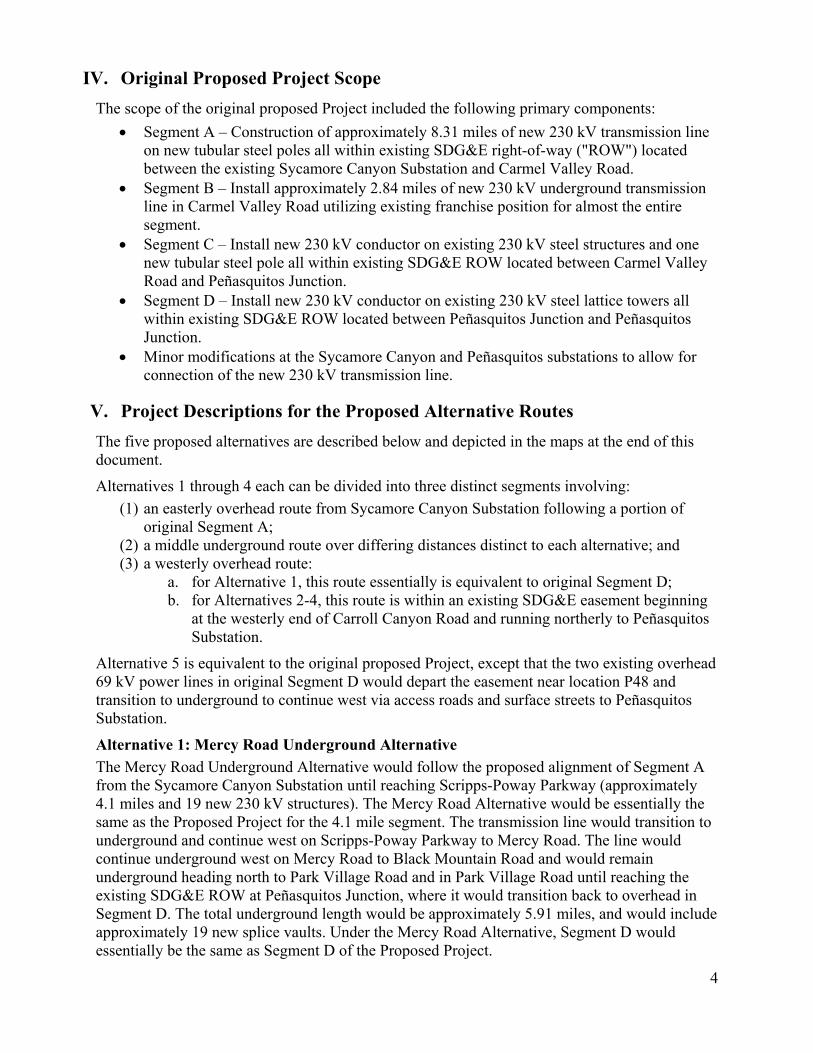
IV. Original Proposed Project Scope
The scope of the original proposed Project included the following primary components:
Segment A – Construction of approximately 8.31 miles of new 230 kV transmission line on new tubular steel poles all within existing SDG&E right-of-way ("ROW") located between the existing Sycamore Canyon Substation and Carmel Valley Road.
Segment B – Install approximately 2.84 miles of new 230 kV underground transmission line in Carmel Valley Road utilizing existing franchise position for almost the entire segment.
Segment C – Install new 230 kV conductor on existing 230 kV steel structures and one new tubular steel pole all within existing SDG&E ROW located between Carmel Valley Road and Peñasquitos Junction.
Segment D – Install new 230 kV conductor on existing 230 kV steel lattice towers all within existing SDG&E ROW located between Peñasquitos Junction and Peñasquitos Junction.
Minor modifications at the Sycamore Canyon and Peñasquitos substations to allow for connection of the new 230 kV transmission line.
V. Project Descriptions for the Proposed Alternative Routes
The five proposed alternatives are described below and depicted in the maps at the end of this document.
Alternatives 1 through 4 each can be divided into three distinct segments involving:
(1) an easterly overhead route from Sycamore Canyon Substation following a portion of original Segment A;
(2) a middle underground route over differing distances distinct to each alternative; and (3) a westerly overhead route:
a. for Alternative 1, this route essentially is equivalent to original Segment D; b. for Alternatives 2-4, this route is within an existing SDG&E easement beginning
at the westerly end of Carroll Canyon Road and running northerly to Peñasquitos Substation.
Alternative 5 is equivalent to the original proposed Project, except that the two existing overhead 69 kV power lines in original Segment D would depart the easement near location P48 and transition to underground to continue west via access roads and surface streets to Peñasquitos Substation.
Alternative 1: Mercy Road Underground Alternative
The Mercy Road Underground Alternative would follow the proposed alignment of Segment A from the Sycamore Canyon Substation until reaching Scripps-Poway Parkway (approximately 4.1 miles and 19 new 230 kV structures). The Mercy Road Alternative would be essentially the same as the Proposed Project for the 4.1 mile segment. The transmission line would transition to underground and continue west on Scripps-Poway Parkway to Mercy Road. The line would continue underground west on Mercy Road to Black Mountain Road and would remain underground heading north to Park Village Road and in Park Village Road until reaching the existing SDG&E ROW at Peñasquitos Junction, where it would transition back to overhead in Segment D. The total underground length would be approximately 5.91 miles, and would include approximately 19 new splice vaults. Under the Mercy Road Alternative, Segment D would essentially be the same as Segment D of the Proposed Project.

5
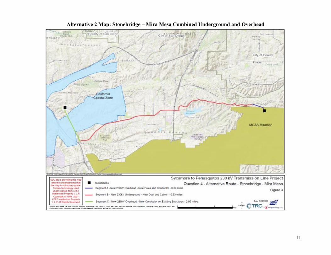
Alternative 2: Stonebridge – Mira Mesa Combined Underground and Overhead
The Stonebridge – Mira Mesa Combined Underground Alternative follows the proposed alignment of Segment A from the Sycamore Canyon Substation to Stonebridge Parkway (approximately 0.89 mile and 3 new 230 kV structures). The Stonebridge – Mira Mesa alternative would then transition to an underground position at Location P05 adjacent to Stonebridge Parkway via a new cable pole (located approximately 340 feet east of Stonecroft Terrace). The alignment would travel west via Stonebridge Parkway to Pomerado Road, then west within Pomerado Road to and continuing within Spring Canyon Road. Where Spring Canyon Road turns north, the route would follow Scripps Ranch Blvd. to the west to the intersection with Mira Mesa Blvd. The route would continue west on Mira Mesa Blvd to Scranton Road, then south until reaching Carroll Canyon Road. The route would then follow Carroll Canyon Road west and would transition to an overhead position via a new cable pole located approximately 150 feet north of Carroll Canyon Road within existing SDG&E ROW. The total underground length is approximately 10.53 miles, and would include approximately 33 new splice vaults. Once in an overhead position, the new 230 kV transmission line would be installed on existing 230 kV structures (within existing SDG&E ROW) for approximately 2.06 miles until reaching the existing Peñasquitos Substation.
Alternative 3: Pomerado – Miramar Area North Combined Underground and Overhead
The Pomerado – Miramar North alternative follows the proposed alignment of Segment A from the Sycamore Canyon Substation to Stonebridge Parkway (approximately 0.89 mile and 3 new 230 kV structures). The Pomerado – Miramar North alternative would then transition to an underground position at Location P05 adjacent to Stonebridge Parkway via a new cable pole located approximately 340 feet east of Stonecroft Terrace. The alignment would travel west via Stonebridge Parkway to Pomerado Road, then west within Pomerado Road to Interstate 15. Since there is not room within the Pomerado/ Miramar Road bridge over Interstate 15, the line would cross over Interstate 15 via four (4) new overhead structures (two cable poles and two dead tubular steel poles). The route would then continue westward underground on Miramar Road, then north on Kearny Villa Road, west on Black Mountain Road, west on Activity Road to Camino Ruiz, north on Camino Ruiz, west on Miralani Drive, west on Arjons Drive, south on Trade Place, west on Trade Street, south on Camino Santa Fe, and west on Carroll Road/Carroll Canyon Road until reaching the site for a new 230 kV cable, located approximately 150 feet north of Carroll Canyon Road and 300 feet east of the I-805 northbound off-ramp within existing SDG&E ROW. The line would transition to an overhead position at the cable pole structure. The total underground length is approximately 11.45 miles (the overhead segment crossing Interstate 15 is approximately 1,300 feet), and would include approximately 35 new splice vaults. Once in an overhead position, the new 230 kV transmission line would be installed on existing 230 kV structures (within existing SDG&E ROW) for approximately 2.06 miles until reaching the existing Peñasquitos Substation.
Alternative 4: Pomerado – Miramar Combined Underground and Overhead
The Pomerado – Miramar alternative follows the proposed alignment of Segment A from the Sycamore Canyon Substation to Stonebridge Parkway (approximately 0.89 mile and 3 new 230 kV structures). The Pomerado – Miramar North alternative would then transition to an underground position at Location P05 adjacent to Stonebridge Parkway via a new cable pole located approximately 340 feet east of Stonecroft Terrace. The alignment would travel west via Stonebridge Parkway to Pomerado Road, then west within Pomerado Road to Interstate 15. Since there is not room within the Pomerado/ Miramar Road bridge over Interstate 15, the line would cross over Interstate 15 via four (4) new overhead structures (two cable poles and two

6
dead tubular steel poles). The route would then continue westward underground beneath Miramar Road to Carroll Road/Carroll Canyon Road where it would continue west on Carroll Road until reaching the site for a new 230 kV cable, located approximately 150 feet north of Carroll Canyon Road and 300 feet east of the I-805 northbound off-ramp within existing SDG&E ROW. The line would transition to an overhead position at the cable pole structure. The total underground length is approximately 10.81 miles (the overhead segment crossing the Interstate 15 is approximately 1,300 feet), and would include approximately 33 new splice vaults. Once in an overhead position, the new 230 kV transmission line would be installed on existing 230 kV structures (within existing SDG&E ROW) for approximately 2.06 miles until reaching the existing Peñasquitos Substation.
Alternative 5: Partial Segment D 69 kV Underground
The Partial Segment D 69 kV Underground alternative would place the two existing 69 kV circuits (TL675 and TL 6906) in an underground position from Location P48 to the Peñasquitos Substation. Similar to the SDG&E Proposed Project, the new 230 kV transmission line would be placed on the southerly side of the existing 230 kV towers located between the Peñasquitos Junction and the Peñasquitos Substation. Also similar to the Proposed Project, existing TL13804 would be relocated to the northerly side of the existing towers. The two 69 kV power lines would transition to an underground position via new cable pole structures near location P48. A segment of the new 69 kV underground approximately 850 feet in length would be installed within an existing unpaved access road between the new cable pole structures and the existing paved Carmel Mountain Road. The underground route would then be located within Carmel Mountain Road heading west, then south on East Ocean Air Drive, and finally west to the Peñasquitos Substation via the existing paved substation access road. The underground 69 kV route would be approximately 3.1 miles long and would require approximately 20 new splice vaults.
7
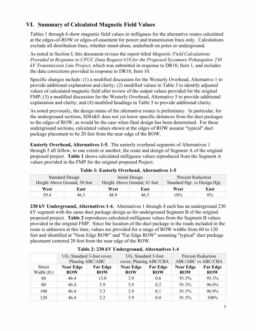
VI. Summary of Calculated Magnetic Field Values
Tables 1 through 6 show magnetic field values in milligauss for the alternative routes calculated at the edges-of-ROW or edges-of-easement for power and transmission lines only. Calculations exclude all distribution lines, whether stand-alone, underbuilt on poles or underground.
As noted in Section I, this document revises the report titled Magnetic Field Calculations Provided in Response to CPUC Data Request #10 for the Proposed Sycamore Peñasquitos 230 kV Transmission Line Project, which was submitted in response to DR10, Item 1, and includes the data corrections provided in response to DR18, Item 10.
Specific changes include: (1) a modified discussion for the Westerly Overhead, Alternative 1 to provide additional explanation and clarity; (2) modified values in Table 3 to identify adjusted values of calculated magnetic field after review of the output values provided for the original FMP; (3) a modified discussion for the Westerly Overhead, Alternative 5 to provide additional explanation and clarity; and (4) modified headings in Table 5 to provide additional clarity.
As noted previously, the design status of the alternative routes is preliminary. In particular, for the underground sections, SDG&E does not yet know specific distances from the duct packages to the edges of ROW, as would be the case when final design has been determined. For these underground sections, calculated values shown at the edges of ROW assume "typical" duct package placement to be 20 feet from the near edge of the ROW.
Easterly Overhead, Alternatives 1-5. The easterly overhead segments of Alternatives 1 through 5 all follow, to one extent or another, the route and design of Segment A of the original proposed project. Table 1 shows calculated milligauss values reproduced from the Segment A values provided in the FMP for the original proposed Project.
Table 1: Easterly Overhead, Alternatives 1-5 Standard Design
Height Above Ground, 30 feet Initial Design
Height Above Ground, 41 feet Percent Reduction
Standard Hgt. vs Design Hgt.
West East West East West East 59.4 46.3 48.9 46.5 18% 0%
230 kV Underground, Alternatives 1-4. Alternatives 1 through 4 each has an underground 230 kV segment with the same duct package design as for underground Segment B of the original proposed project. Table 2 reproduces calculated milligauss values from the Segment B values provided in the original FMP. Since the location of the duct package in the roads included in the route is unknown at this time, values are provided for a range of ROW widths from 60 to 120 feet and identified at "Near Edge ROW" and "Far Edge ROW" assuming "typical" duct package placement centered 20 feet from the near edge of the ROW.
Table 2: 230 kV Underground, Alternatives 1-4
UG, Standard 3-foot cover, Phasing ABC/ABC
UG, Standard 3-foot cover, Phasing ABC/CBA
Percent Reduction ABC/ABC vs ABC/CBA
Street Width (ft.)
Near Edge ROW
Far Edge ROW
Near Edge ROW
Far Edge ROW
Near Edge ROW
Far Edge ROW
60 46.4 13.0 3.9 0.6 91.5% 95.3%
80 46.4 5.9 3.9 0.2 91.5% 96.6%
100 46.4 3.3 3.9 0.1 91.5% 96.9%
120 46.4 2.2 3.9 0.0 91.5% 100%

8
Westerly Overhead, Alternative 1. The westerly overhead segment of Alternative 1 follows the route and design of Segment D of the original proposed project.
SDG&E has determined that in calculating the values provided in the original FMP, the process of importing the data files created in the RESICALC modeling software into the Workstation modeling software re-set the power flow directions of the source model to be all in one direction, and reversed the north and south edges of ROW.5 This resulted in a misstatement of values for the north and south edges of ROW in the original FMP. The calculation models for Segment D of Alternative 1 include appropriate adjustments to the imported file for power flow direction and north/south edges of ROW.
Table 3A shows the calculated milligauss values as provided for Segment D in the original FMP. Table 3B shows calculated values for Segment D of Alternative 1. Both sets of values are based on models using the initial design conductor height above ground, which is eleven (11) feet greater than standard design height.
A full table of values for Segment D, Alternative 1 was provided on pages 61-74 of the attachment SX-PQ_ValuesAcrossROW_Proposed&AlternativeRoutes.pdf as part of SDG&E's response to Data Request #18.
Table 3A: Segment D Values in Original FMP
Table 3B: Westerly Overhead, Alternative 1
Values Provided in Original FMP Adjusted Values
North South North South 9.5 135.9 71.8 1.8
Westerly Overhead, Alternatives 2-4. The westerly overhead segment of Alternatives 2 through 4 involves a route and design not included in the original proposed project. This segment is divided into four sub-segments based on varying cross-sectional circuit placement:
Sub-segment 1, Carroll Canyon Road – Mira Sorrento Place Sub-segment 2, Mira Sorrento Place – Wateridge Circle Sub-segment 3, Wateridge Circle – Sorrento Valley Blvd Sub-segment 4, Sorrento Valley Blvd – Peñasquitos Substation
Table 4 shows new calculated milligauss values for the four sub-segments of the route, beginning at the westerly end of Carroll Canyon Road and running north to Peñasquitos Substation.
Table 4: Westerly Overhead, Alternatives 2-4
New 230 kV, Standard Phasing ABC/ABC
New 230 kV, Reverse Phasing ABC/CBA
Percent Reduction ABC/ABC vs ABC/CBA
Sub-segment West East West East West East 1 23.5 79.1 25.0 46.3 -6.3% 41.4%
2 35.4 61.8 58.6 59.6 -65.5% 3.5%
3 41.0 65.4 12.3 55.8 70.0% 14.6%
4 35.4 62.5 43.0 58.3 -21.4% 6.7%
Note: A minus percent reduction value indicates an increase in magnetic field value.
5 SDG&E response to Commission Data Request #18

9
Westerly Overhead, Alternative 5. Alternative 5 differs from the original proposed project alignment only in Segment D. For this alternative, Segment D was considered to have two components:
(1) Alt 5 with 69 kV in which the two existing 69 kV power lines TL 675 and TL 6906 remain in an overhead position in the right-of-way from Peñasquitos Junction to a point new cable pole structures near Location P48, where they transition to an underground route outside of the east-west right-of-way containing TL13804 and the proposed new 230 kV line;
(2) Alt 5 without 69 kV from Location P48 to Peñasquitos Substation, in which the two existing 69 kV power lines TL 675 and TL 6906 are no longer in the east-west right-of-way containing TL13804 and the proposed new 230 kV line.
Table 5 shows new calculated milligauss values for Component 1 (Alt 5 with 69 kV) and Component 2 (Alt 5 without 69 kV) of the Alternative 5 westerly overhead route.
Table 5: Westerly Overhead, Alternative 5 – with 69 kV and without 69 kV Alt 5 with 69 kV
(from Peñasquitos Junction to Location P48)
Alt 5 without 69 kV (from Location P48 to
Peñasquitos Substation) Percent Reduction
with 69 kV vs without 69 kV
North (A) South (B) North (C) South (D) North
(A vs C) South
(B vs D) 71.8 1.8 79.2 3.3 -10.3% -83.3%
Note: A minus percent reduction value indicates an increase in magnetic field value.
Westerly 69 kV Underground, Alternative 5. Table 6 shows new calculated milligauss values for the Alternative 5 double-circuit 69 kV underground route. Since the location of the duct package in the roads included in the route is unknown at this time, values are provided for a range of ROW widths from 60 to 120 feet and identified at "Near Edge ROW" and "Far Edge ROW" assuming "typical" duct package placement centered 20 feet from the near edge of ROW.
Table 6: Westerly 69 kV Underground, Alternative 5
If duct package placed on north or west side of street UG, Standard 3-foot
cover, Phasing ABC/ABC UG, Standard 3-foot
cover, Phasing ABC/CBA Percent Reduction
ABC/ABC vs ABC/CBA Street Width
(ft.) Near Edge
ROW Far Edge
ROW Near Edge
ROW Far Edge
ROW Near Edge
ROW Far Edge
ROW 60 18.5 5.0 8.3 1.8 55.7% 64.0%
80 18.5 2.3 8.3 0.9 55.7% 60.8%
100 18.5 1.3 8.3 0.5 55.7% 61.5%
120 18.5 0.8 8.3 0.3 55.7% 62.5%
If duct package placed on south or east side of street UG, Standard 3-foot cover
Phasing ABC/ABC UG, Standard 3-foot cover
Phasing ABC/CBA Percent Reduction
ABC/ABC vs ABC/CBA Street Width
(ft.) Near Edge
ROW Far Edge
ROW Near Edge
ROW Far Edge
ROW Near Edge
ROW Far Edge
ROW 60 18.5 5.1 8.3 2.2 55.2% 56.8%
80 18.5 2.3 8.3 1.0 55.2% 56.5%
100 18.5 1.3 8.3 0.5 55.2% 61.5%
120 18.5 0.8 8.3 0.3 55.2% 62.5%

10
Maps of the Five Proposed Alternative Routes for the Project Alternative 1: Mercy Road Underground Alternative
11
Alternative 2 Map: Stonebridge – Mira Mesa Combined Underground and Overhead

12
Alternative 3 Map: Pomerado – Miramar Area North Combined Underground and Overhead

13
Alternative 4 Map: Pomerado – Miramar Combined Underground and Overhead

14
Alternative 5 Map: Partial Segment D 69 kV Underground