Embed Size (px)
Citation preview

AT/RD-07 1
Proton LINAC for the Frankfurt Neutron Source FRANZ
O. Meusel1, A. Bechtold
1, L.P. Chau
1, M. Heilmann
1, H. Podlech
1, U. Ratzinger
1, A.
Schempp1, C. Wiesner
1, S. Schmidt
1, K. Volk
1, M. Heil
2, R. Plag
2, R. Reifarth
2, K. Stiebing
3,
J. Stroth3, F. Käppeler
4, D. Petrich
4
1
IAP, Goethe University, Frankfurt, Germany
2 GSI, Darmstadt, Germany
3 IKF, Goethe University, Frankfurt, Germany
4 IKF, FZ Karlsruhe, Germany
Email contact of main author: [email protected]
Abstract. The Frankfurt Neutron Source at Stern - Gerlach - Zentrum (FRANZ) will use the 7Li(p,n) reaction
to produce a intense neutron beam. The planned experiments require an adjustable neutron energy between 10
and 250 keV. Hence the energy of primary proton beam should be adjustable between 1.8 MeV and 2.2 MeV.
The FRANZ beam line consists of two branches to allow different methods of neutron capture measurements.
The compressor mode offer time of flight measurements in combination with a 4πBaF2 detector array. The
proton beam of about 150 mA will be compressed to a 1ns pulse with a peak current of about 8 A at the
repetition rate of 250 kHz. The activation mode uses a continuous neutron flux. The primary cw proton beam
with a low current up to 30 mA will be focussed onto the production target.
FRANZ is not only a neutron generator but also a test bench for new accelerator and diagnostic concepts for
intense ion beams. The planned proton beam properties on the target leads into a challenge accelerator design to
overcome the space charge forces. This presentation emphasises on the ongoing construction of the proton
injector.
1. Introduction
Institute of Applied Physics (IAP) has an international expertise for the development of
accelerator concepts. The design of the low energy part of the EUROTRANS proton driver
LINAC is an example of actual activities [1]. For further developments an accelerator test
bench was planned at Stern-Gerlach-Zentrum to proof new accelerator components and beam
diagnostic tools. A volume type ion source will deliver a 120keV, 200mA proton beam
continuously. A LEBT section consisting of four solenoids is under construction to transport
the beam and to match it into the acceptance of the RFQ. A chopper system between solenoid
2 and 3 will provide beam pulses with a length of about 50 to 100 ns with a repetition rate of
up to 250 kHz. The RFQ and the following IH drift tube LINAC will be coupled together to
achieve an efficient beam acceleration. Furthermore only one power amplifier will be needed
to provide the RF power for both accelerator stages. The Mobley type bunch compressor will
merge 8 micro bunches formed in the accelerator module to one single 1ns bunch with an
estimated peak current of up to 9.6 A. A rebuncher will provide the post acceleration to final
beam energy adjustable between 1.8 and 2.2 MeV [2]. The whole system is optimized for
high beam intensity causing high space charge forces. FRANZ comprises two operation
modes. At compressor mode the proton beam will be compressed to a 1ns pulse with a peak
current of about 9.6 A and a repetition rate of 250 kHz. Activation mode uses a continuous
(cw) proton beams with a current up to 8 mA on solid targets and up to 30 mA on liquid metal
targets as a later option are feasible. Target development in cooperation with FZ Karlsruhe
and GSI is planned to overcome the expected power density. Figure 1 shows the conversion
of primary proton beam properties into neutron beam properties for the compressor mode.
After collimation the pulsed neutron beam with length of 1ns offers time of flight
measurements in combination with a 4π BaF2 detector array.

AT/RD-07 2
Neutron beam
Energy: 10 - 250 keV
Production rate:
Neutron flux at the target:
Neutron production
target and detector – with kindly support by
FZK and GSI.
low energy proton beam
Beam energy: 120 keV
Beam current: 200 mA
Pulse width: 50 - 150 ns
7 7Li p n Be( , )→
Proton beam at the target
Final energy (adjustable): 1,8 - 2,2 MeV
Repetition rate: 100 - 250 kHz
Pulse width : 1 ns
≤ ⋅ → ≤ ⋅2 10 5 105 10n / pulse n / s
≤ → ≤ ⋅ → ≤ ⋅120 3 1 n / pulse 10 n/ s 10 n/ cm s7 7 2
FIG. 1. Scheme of conversion primary proton beam into collimated neutron beam for the compressor
mode.
For both of these two operation modes the neutron energy will be adjustable by the primary
proton beam energy. The maximum neutron energy of about 250keV is limited by the
radiation protection.
2. The Proton LINAC
The proton LINAC consists of a 150kV terminal with volume source, low energy beam
transport section, coupled RF accelerator stages followed by a bunch compressor of Mobley
type. Two rebuncher cavities, for activation and compressor mode, provide a proton beam
energy variation between 1.8 and 2.2MeV. Figure 2 shows an overview of the LINAC with
estimated beam properties.
FIG. 2. Scheme of the Frankfurt Neutron Source at Stern-Gerlach-Zentrum (FRANZ).
2.1. Ion Source
A volume type ion source was chosen for FRANZ to extract the proton beam from a hot
filament driven gas discharge plasma [3]. Figure 3 shows this source type. The life time of the
filament is limited to about two weeks of operation. The plasma temperature of a gas
discharge due to moderate arc power is as well as the confining magnetic field very low

AT/RD-07 3
compared with other source types e.g. ECR sources. Therefore the beam emittance is small
and gives the possibility to investigate causes of emittance growth during beam transport and
acceleration along the whole LINAC.
FIG. 3. Cross sectional view of the hot filament driven gas discharge ion source.
For the planned beam intensities a pentode extraction system keeps quite well the beam
emittance during the extraction and pre acceleration phase when compared with other
extraction schemes [4]. Numerical simulation of the beam extraction by the use of the IGUN
code [5] were made under respect of a multi species beam with approximately H+ = 80%, H2
+
= H3+ 10%. The chosen aspect ratio of S = 0.2, an emission area of 0.78 cm
2 and an extraction
field strength of 6.2 kV/mm results in a beam radius of rbeam = 5 mm, in an emittance of εrms =
0.06 π mm mrad and a divergence angle of r’ = 74.5 mrad.
2.2. Low Energy Beam Transport
The LEBT section consists of 4 solenoids for beam focussing and includes partial of space
charge compensation due to residual gas ionisation. Figure 4 shows a scheme of the planned
LEBT. The first and second solenoid will be used for separation of ion species and to match
the proton beam into the chopper system. Downstream of the chopper two solenoids will
focus the beam into the acceptance of the RFQ. Two pumping and diagnostic tanks will be
used for several non interceptive diagnostics e.g. optical beam profile measurement and beam
potential measurements using a residual gas ion energy analyzer. The chopper system
consisting of a kicker and a septum magnet combined with a slit provide the 100 ns proton
beam pulses. A fast magnetic or electric kicker deflects the beam with a repetition rate of 250
kHz whereas the static septum magnet provides the post separation and a pulse with a flat top
of at least 50 ns. Comparison of electric and magnetic kicker systems by the use of numerical
simulation shows an influence of secondary electrons. The high production rate of electrons in
the chopper system gives the possibility for partial space charge compensation of short beam
pulses. Preliminary studies result in approximately 30% of space charge compensation by the
use of a magnetic kicker system. For an electric kicker the secondary electrons bear the risk of
sparking and sputtering from the electrodes [6]. Beam transport and chopping leads to an
emittance growth at a factor of 4. It seems possible to reduce this value by further
optimization of beam transport with respect to the filling degree of the solenoids and more
detailed analysis of space charge compensation. Pulsed beam with proton densities of np =
AT/RD-07 4
8.2·1014
m-3
, generalized perveance of K = 3.1·103
and pulse length of about 100ns will be
injected in the coupled RFQ-IH DTL.
FIG. 4. Scheme of the Low energy Beam Transport section with chopper system in between four
solenoids.
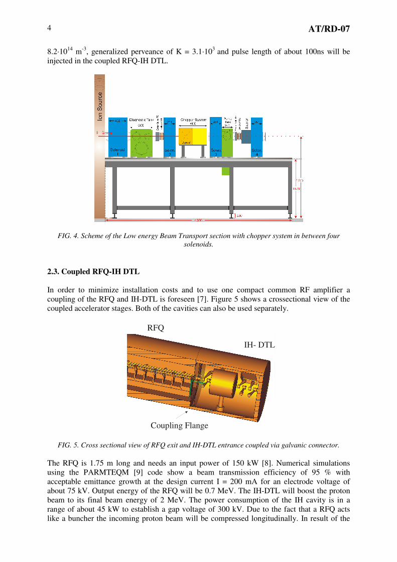
2.3. Coupled RFQ-IH DTL
In order to minimize installation costs and to use one compact common RF amplifier a
coupling of the RFQ and IH-DTL is foreseen [7]. Figure 5 shows a crossectional view of the
coupled accelerator stages. Both of the cavities can also be used separately.
Coupling Flange
IH- DTL
RFQ
FIG. 5. Cross sectional view of RFQ exit and IH-DTL entrance coupled via galvanic connector.
The RFQ is 1.75 m long and needs an input power of 150 kW [8]. Numerical simulations
using the PARMTEQM [9] code show a beam transmission efficiency of 95 % with
acceptable emittance growth at the design current I = 200 mA for an electrode voltage of
about 75 kV. Output energy of the RFQ will be 0.7 MeV. The IH-DTL will boost the proton
beam to its final beam energy of 2 MeV. The power consumption of the IH cavity is in a
range of about 45 kW to establish a gap voltage of 300 kV. Due to the fact that a RFQ acts
like a buncher the incoming proton beam will be compressed longitudinally. In result of the

AT/RD-07 5
beam transport simulation the micro bunch phase width is in a range of 60 degree. The
average bunch current increases up to 1.2 A and the resulting compression ratio is η = 6. At
beam energy of 2 MeV downstream of the accelerator stages the proton density is np =
8.2·1014
m-3
and the space charge forces expressed by the generalized perveance decreases of
about K = 2.7·104. A following CH-cavity is planned to provide the beam energy variation
from just below the threshold of neutron production reaction up to 2.2 MeV. For compressor
mode these cavity will be used for longitudinal focussing to prevent an increase of the bunch
duration of 1 ns.
2.4. Bunch Compressor
By applying the bunch compressor concept of the Mobley type [10] for high current beams a
split magnetic dipole array include edge focusing was chosen [11]. The periodic deflection by
the RF kicker at one focus of the bending system guides up to 9 bunches on different paths to
the final focus, where the neutron production target is located. As shown in figure 6 in front of
the target an additionally rebuncher cavity will be used for energy variation of about ±0.2
MeV of the primary proton beam and longitudinal focussing.
FIG. 6. Scheme of the bunch compressor, beam from LINAC will be guided to 9 traces (blue) through
the compressor array.
By choosing adequate parameters all 9 bunches will overlap at the target and produce a 1.1 ns
proton pulse with a proton density of np = 8.2·1014 m-3
. Space charge forces become
dominant, the generalized perveance is K = 2.2·10-3
. The peak current is 9.6 A and the
resulting compression ratio downstream of the whole proton injector is of η = 48.
3. Target Design
The possibility to build a neutron production target for high beam powers of up to 4 kW
shown in figure 7 has been investigated [12]. It was shown that a robust solution can be
obtained consisting of a copper backing 1.2 mm in thickness. Cooling is provided by water
flowing through capillaries 0.6 mm in diameter and with a spacing of 1.0 mm at a pressure of
50 bar. This concept was subject to computer simulations, which demonstrated that the
moderation effect of the cooling water is acceptable and that the surface temperature at 4kW
beam power does not exceed 300 °C, sufficiently low if a high temperature Li compound is
used as target material.
AT/RD-07 6
FIG. 7. Scheme of neutron production target with cooling water connections.
Two prototype versions have been built with equivalent cooling properties, but different
degrees of complexity. One of these targets has been successfully tested at the Karlsruhe 3.7
MV Van de Graaf accelerator, where a power density of 5 kW/cm2 has been reached by
focusing the beam into a spot 3 mm in diameter. This implies that the target is well suited for
the FRANZ facility, where the power density in compressor mode operation is restricted to
values below 4 kW/cm2 due to space charge limitations.
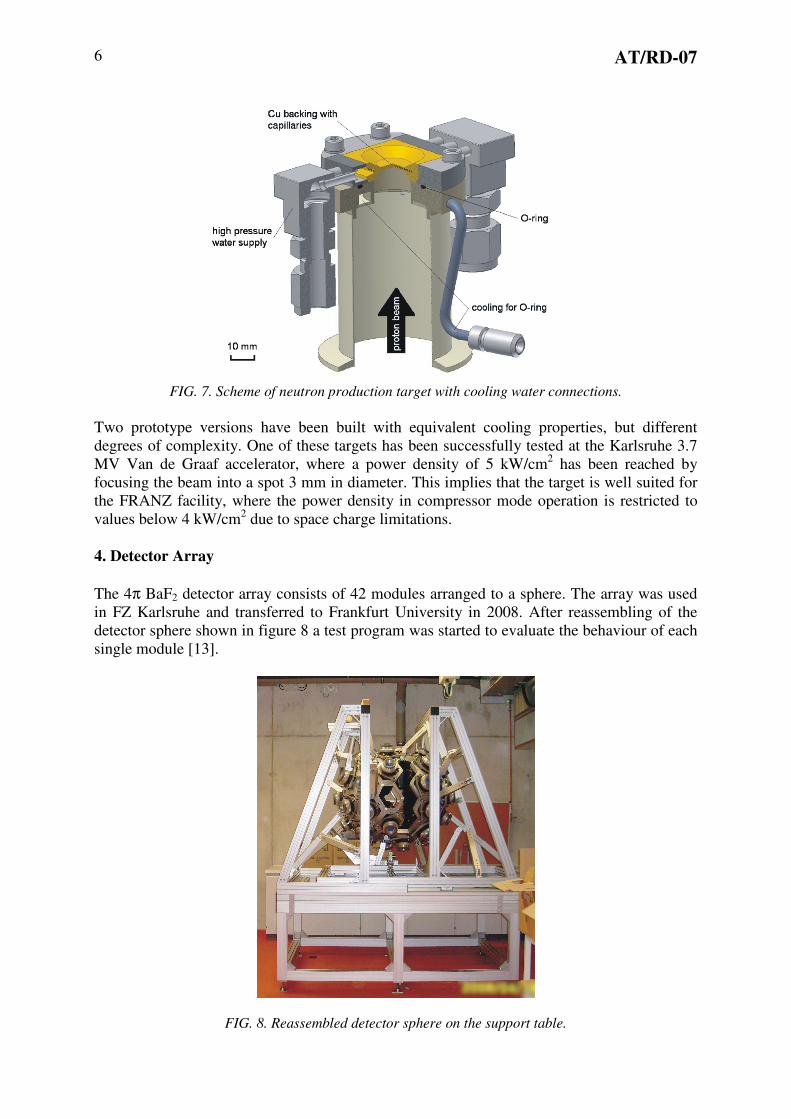
4. Detector Array
The 4π BaF2 detector array consists of 42 modules arranged to a sphere. The array was used
in FZ Karlsruhe and transferred to Frankfurt University in 2008. After reassembling of the
detector sphere shown in figure 8 a test program was started to evaluate the behaviour of each
single module [13].
FIG. 8. Reassembled detector sphere on the support table.

AT/RD-07 7
The transfer of the 4π BaF2 detector array from Karlsruhe to Frankfurt was a success. The
majority of the modules have been proven to function correctly. In result figure 9 shows the
energy resolution of a single module (left) and the time resolution of all modules (left).
FIG. 9. Exemplary energy resolution of module 23 (left) and time resolution of the detector modules
measured using a 60
Co probe after reassembling of the detector sphere in Frankfurt.
5. Summary
FRANZ will be a multi purpose experiment that offers the possibility of accelerator and target
as well as nuclear astrophysics experiments. The approximated collimated neutron flux of
about 107 n/cm
2s ensures good statistical results by the use of small probes of rare isotopes.
Measurement of stellar neutron capture cross sections will continue the research activities of
FZ Karlsruhe at higher neutron fluxes. Interaction of intense neutron beams with different
kinds of materials is important for reactor design as well as measurement of cross sections for
neutron induced fission reactions. Both, development of new accelerator concepts and
estimation of nuclear data especially neutron reaction cross sections, are needed for future
accelerator driven systems (ADS).
6. Acknowledgment
The authors thank IAEA for supporting the transfer of the 4πBaF2 detector array from
Karlsruhe to Frankfurt and GSI as well as FZ Karlsruhe for the kindly support of the project.
Referenzes
[1] H. Podlech et al.,“The 600 MeV Eurotrans Proton Driver LINAC”, these Proceedings,
AT/INT-03
[2] O. Meusel et al, "Development of an intense Neutron source ”FRANZ” in Frankfurt”,
Proc. LINAC 2006, Knoxville
[3] R. Nörenberg, U. Ratzinger, K. Volk, “Development of a high efficiency proton source for
the Frankfurter-Neutronen-Quelle am Stern-Gerlach-Zentrum”, Rev. Sci. Instrum. 79,
02B316 (2008);

AT/RD-07 8
[4] R. Hollinger, P. Spädtke, "Comparison of different extraction and acceleration systems for
a high intense proton beam for the future proton linac at GSI", Rev. Sci. Instrum. 75, 1656
(2004)
[5] R. Becker, W. B. Herrmannsfeldt, "IGUN a program for the simulation of positive ion
extraction including magnetic fields", Rev. Sci. Instrum. 63, 2756 (1992)
[6] C. Wiesner et al., "A 250 kHz Chopper for Low Energy High Intensity Proton Beams",
Proc. of the Eur. Part. Acc. Conf., Genua (2008).
[7] A. Bechtold et al., "A Coupled RFQ-Drifttube Combination for FRANZ", Proceedings of
LINAC 2008, Victoria, Canada
[8] C. Zhang et al., “Development of a High Current Proton Linac for FRANZ”, EPAC’06,
ID: 2342 - THPCH007
[9] LANL Manual of RFQ Design Codes (LANL Report No. LA-UR-96-1836), 1996.
[10] R.C. Mobley, “Proposed Method for Producing Short Intense Monoenergetic Ion
Pulses”, Phys. Rev.88(2), 360-361, 1951
[11] L. P. Chau et al., "One Nano-second Bunch Compressor for High Intense Proton Beam",
Proc. of the Eur. Part. Acc. Conf., Genua (2008).
[12] D. Petrich, F. Käppeler et al., "A neutron production target for FRANZ", Nuclear
Instruments and Methods in Physics Research A 596 (2008) 269–275.
[13] S. Schmidt, "Gamma measurements with the 4π BaF2 detector for the FRANZ facility",
Hochschulpublikationssys., http://publikationen.ub.uni-frankfurt.de/volltexte/2009/6269/
Bachelor Thesis, 2009, University Frankfurt.