Embed Size (px)
Citation preview
STATUS OF THE TOP-IMPLART PROTON LINAC
P. Nenzi, A. Ampollini, G. Bazzano, F. Marracino, L. Picardi, C. Ronsivalle, V. Surrenti, M. Vadrucci, ENEA C.R. Frascati, Frascati, Italy
C. Snels, ENEA Casaccia, Roma, Italy F. Ambrosini, DIET - University «La Sapienza», Roma, Italy
Abstract In this work we present the latest update on the
construction of the TOP-IMPLART proton LINAC at the ENEA C.R. Frascati Accelerators Laboratory. TOP-IMPLART is a 150 MeV proton accelerator for protontherapy applications funded by Regione Lazio (Italy). We have successfully commissioned the first 3GHz LINAC structure reaching the energy of 11.6 MeV (from 7 MeV), demonstrating the first proton acceleration in a SCDTL structures at this energy. The second SCDTL LINAC has been tuned and brazed and in delivery to the installation site, the third one is under construction.
INTRODUCTION The TOP-IMPLART (Intensity Modulated Proton
Linear Accelerator for RadioTherapy) accelerator [1-3] is a proton LINAC designed for medical applications (i.e. cancer treatment). This project, funded by the local government (Regione Lazio), is a joint venture of three Italian research institutions: ENEA, ISS, and IRE-IFO (the end-user). The accelerator, when completed, will deliver a proton beam with energy variable in the 85 MeV to 150MeV range (with a planned upgrade to 230 MeV, not yet funded). The funded TOP-IMPLART accelerator consists of three sections, an injector (up to 7 MeV), a medium energy section (7 MeV to 35 MeV), and a high-energy section (35 MeV to 150 MeV). The injector is a commercial LINAC, the PL-7 designed by Hitachi-AccSys, operating at 425 MHz with 100 μs wide pulses and a pulse repetition frequency (PRF) of 100 Hz (maximum). The rest of the accelerator operates at 2997.92 MHz with a pulse width of 4 μs. The medium energy section consists of four SCDTL (Side Coupled Drift Tube LINAC), an ENEA patented design, driven by a single 10MW klystron tube. The high-energy section of consists of 12 CCL structures driven by four 10MW klystron tubes.
The injector section is connected to the first SCTDL structure by a LEBT (Low Energy Beam Transfer Line) consisting of a first quadrupole doublet followed by a deflecting magnet and a second quadrupole doublet. The LEBT is meant to focus the beam to fit the SCDTL pipe that has 4 mm diameter, whereas the injector pipe is 35mm diameter. The deflecting magnet is used to deliver the proton beam to a vertical beam-line used in radiobiology experiments [4-6].
The operating frequencies of the injector and of the other LINACs are not in harmonic relation and phase synchronization between the two is not achievable. Phase
synchronization strategy of the medium- and high-energy sections is presented in [7].
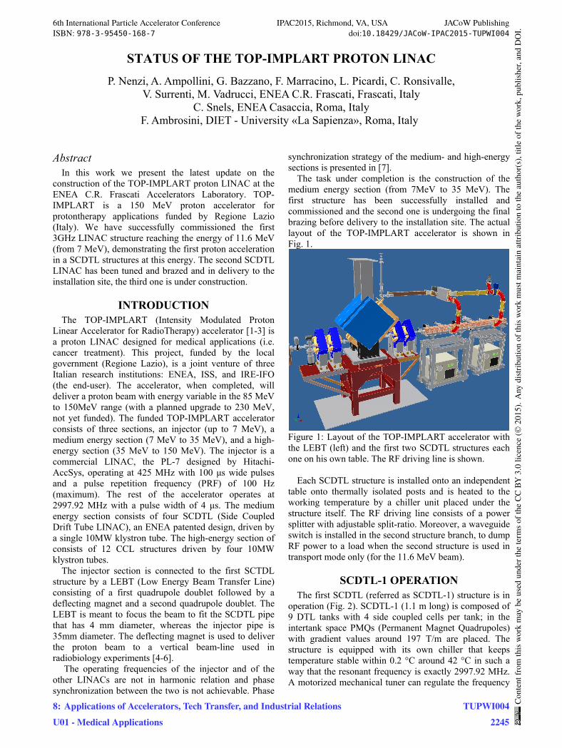
The task under completion is the construction of the medium energy section (from 7MeV to 35 MeV). The first structure has been successfully installed and commissioned and the second one is undergoing the final brazing before delivery to the installation site. The actual layout of the TOP-IMPLART accelerator is shown in Fig. 1.
Figure 1: Layout of the TOP-IMPLART accelerator with the LEBT (left) and the first two SCDTL structures each one on his own table. The RF driving line is shown.
Each SCDTL structure is installed onto an independent table onto thermally isolated posts and is heated to the working temperature by a chiller unit placed under the structure itself. The RF driving line consists of a power splitter with adjustable split-ratio. Moreover, a waveguide switch is installed in the second structure branch, to dump RF power to a load when the second structure is used in transport mode only (for the 11.6 MeV beam).
SCDTL-1 OPERATION The first SCDTL (referred as SCDTL-1) structure is in
operation (Fig. 2). SCDTL-1 (1.1 m long) is composed of 9 DTL tanks with 4 side coupled cells per tank; in the intertank space PMQs (Permanent Magnet Quadrupoles) with gradient values around 197 T/m are placed. The structure is equipped with its own chiller that keeps temperature stable within 0.2 °C around 42 °C in such a way that the resonant frequency is exactly 2997.92 MHz. A motorized mechanical tuner can regulate the frequency
6th International Particle Accelerator Conference IPAC2015, Richmond, VA, USA JACoW PublishingISBN: 978-3-95450-168-7 doi:10.18429/JACoW-IPAC2015-TUPWI004
8: Applications of Accelerators, Tech Transfer, and Industrial RelationsU01 - Medical Applications
TUPWI0042245
Cont
entf
rom
this
wor
km
aybe
used
unde
rthe
term
soft
heCC
BY3.
0lic
ence
(©20
15).
Any
distr
ibut
ion
ofth
isw
ork
mus
tmai
ntai
nat
tribu
tion
toth
eau
thor
(s),
title
ofth
ew
ork,
publ
isher
,and
DO
I.
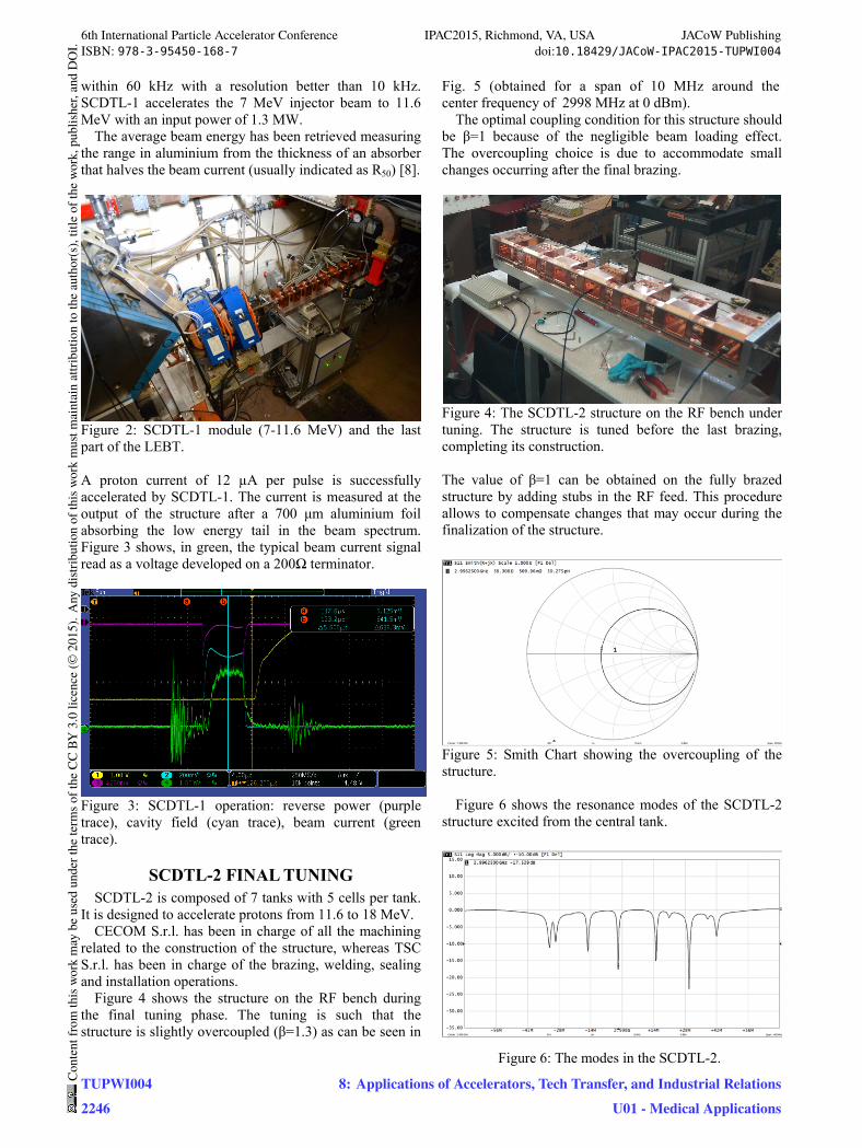
within 60 kHz with a resolution better than 10 kHz. SCDTL-1 accelerates the 7 MeV injector beam to 11.6 MeV with an input power of 1.3 MW.
The average beam energy has been retrieved measuring the range in aluminium from the thickness of an absorber that halves the beam current (usually indicated as R50) [8].
Figure 2: SCDTL-1 module (7-11.6 MeV) and the last part of the LEBT. A proton current of 12 µA per pulse is successfully accelerated by SCDTL-1. The current is measured at the output of the structure after a 700 μm aluminium foil absorbing the low energy tail in the beam spectrum. Figure 3 shows, in green, the typical beam current signal read as a voltage developed on a 200Ω terminator.
Figure 3: SCDTL-1 operation: reverse power (purple trace), cavity field (cyan trace), beam current (green trace).
SCDTL-2 FINAL TUNING SCDTL-2 is composed of 7 tanks with 5 cells per tank.
It is designed to accelerate protons from 11.6 to 18 MeV. CECOM S.r.l. has been in charge of all the machining
related to the construction of the structure, whereas TSC S.r.l. has been in charge of the brazing, welding, sealing and installation operations.
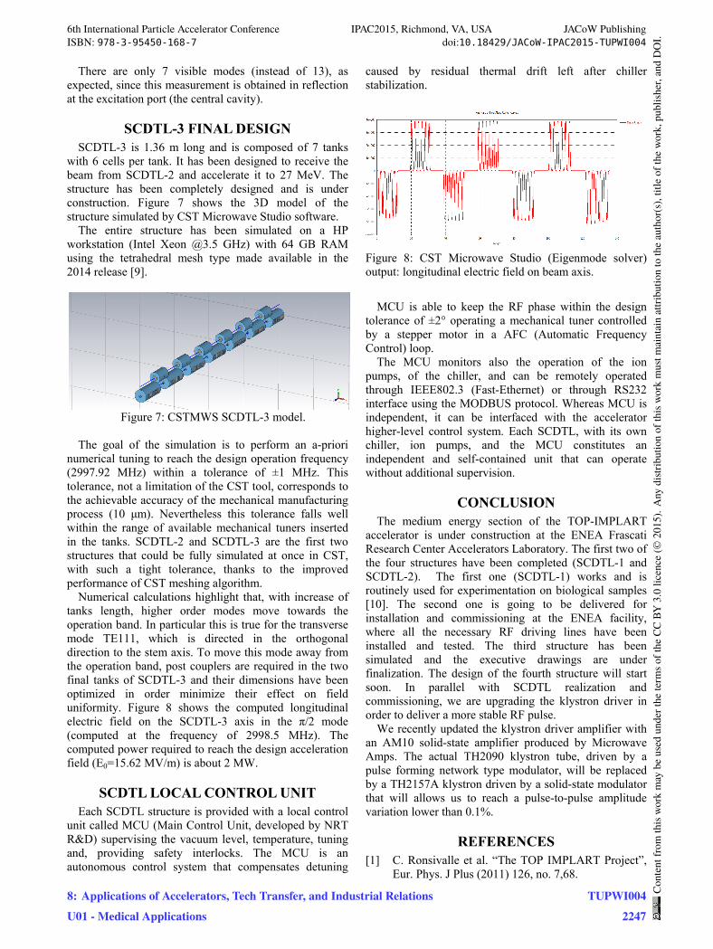
Figure 4 shows the structure on the RF bench during the final tuning phase. The tuning is such that the structure is slightly overcoupled (β=1.3) as can be seen in
Fig. 5 (obtained for a span of 10 MHz around the center frequency of 2998 MHz at 0 dBm).
The optimal coupling condition for this structure should be β=1 because of the negligible beam loading effect. The overcoupling choice is due to accommodate small changes occurring after the final brazing.
Figure 4: The SCDTL-2 structure on the RF bench under tuning. The structure is tuned before the last brazing, completing its construction. The value of β=1 can be obtained on the fully brazed structure by adding stubs in the RF feed. This procedure allows to compensate changes that may occur during the finalization of the structure.
Figure 5: Smith Chart showing the overcoupling of the structure.
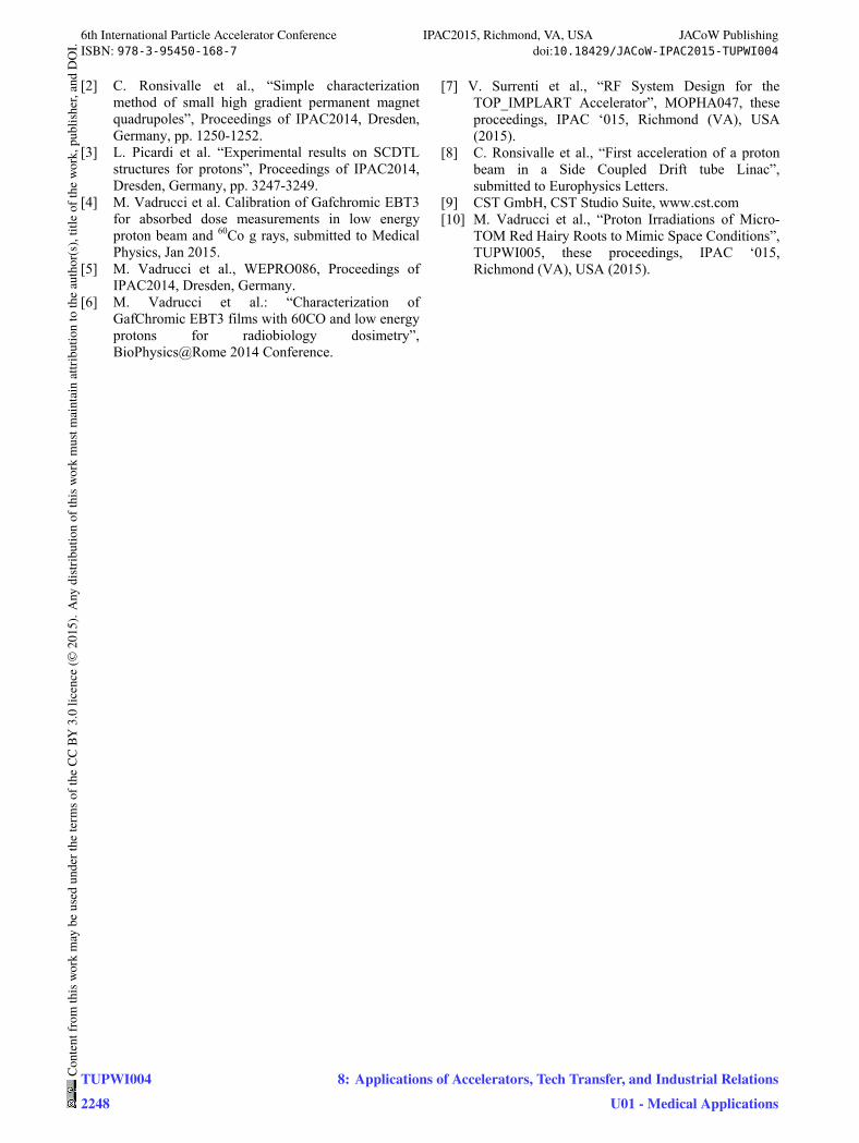
Figure 6 shows the resonance modes of the SCDTL-2
structure excited from the central tank.
Figure 6: The modes in the SCDTL-2.
6th International Particle Accelerator Conference IPAC2015, Richmond, VA, USA JACoW PublishingISBN: 978-3-95450-168-7 doi:10.18429/JACoW-IPAC2015-TUPWI004
TUPWI0042246
Cont
entf
rom
this
wor
km
aybe
used
unde
rthe
term
soft
heCC
BY3.
0lic
ence
(©20
15).
Any
distr
ibut
ion
ofth
isw
ork
mus
tmai
ntai
nat
tribu
tion
toth
eau
thor
(s),
title
ofth
ew
ork,
publ
isher
,and
DO
I.
8: Applications of Accelerators, Tech Transfer, and Industrial RelationsU01 - Medical Applications
There are only 7 visible modes (instead of 13), as expected, since this measurement is obtained in reflection at the excitation port (the central cavity).
SCDTL-3 FINAL DESIGN SCDTL-3 is 1.36 m long and is composed of 7 tanks
with 6 cells per tank. It has been designed to receive the beam from SCDTL-2 and accelerate it to 27 MeV. The structure has been completely designed and is under construction. Figure 7 shows the 3D model of the structure simulated by CST Microwave Studio software.
The entire structure has been simulated on a HP workstation (Intel Xeon @3.5 GHz) with 64 GB RAM using the tetrahedral mesh type made available in the 2014 release [9].
Figure 7: CSTMWS SCDTL-3 model.
The goal of the simulation is to perform an a-priori
numerical tuning to reach the design operation frequency (2997.92 MHz) within a tolerance of ±1 MHz. This tolerance, not a limitation of the CST tool, corresponds to the achievable accuracy of the mechanical manufacturing process (10 μm). Nevertheless this tolerance falls well within the range of available mechanical tuners inserted in the tanks. SCDTL-2 and SCDTL-3 are the first two structures that could be fully simulated at once in CST, with such a tight tolerance, thanks to the improved performance of CST meshing algorithm.
Numerical calculations highlight that, with increase of tanks length, higher order modes move towards the operation band. In particular this is true for the transverse mode TE111, which is directed in the orthogonal direction to the stem axis. To move this mode away from the operation band, post couplers are required in the two final tanks of SCDTL-3 and their dimensions have been optimized in order minimize their effect on field uniformity. Figure 8 shows the computed longitudinal electric field on the SCDTL-3 axis in the π/2 mode (computed at the frequency of 2998.5 MHz). The computed power required to reach the design acceleration field (E0=15.62 MV/m) is about 2 MW.
SCDTL LOCAL CONTROL UNIT Each SCDTL structure is provided with a local control
unit called MCU (Main Control Unit, developed by NRT R&D) supervising the vacuum level, temperature, tuning and, providing safety interlocks. The MCU is an autonomous control system that compensates detuning
caused by residual thermal drift left after chiller stabilization.
Figure 8: CST Microwave Studio (Eigenmode solver) output: longitudinal electric field on beam axis.
MCU is able to keep the RF phase within the design
tolerance of ±2° operating a mechanical tuner controlled by a stepper motor in a AFC (Automatic Frequency Control) loop.
The MCU monitors also the operation of the ion pumps, of the chiller, and can be remotely operated through IEEE802.3 (Fast-Ethernet) or through RS232 interface using the MODBUS protocol. Whereas MCU is independent, it can be interfaced with the accelerator higher-level control system. Each SCDTL, with its own chiller, ion pumps, and the MCU constitutes an independent and self-contained unit that can operate without additional supervision.
CONCLUSION The medium energy section of the TOP-IMPLART
accelerator is under construction at the ENEA Frascati Research Center Accelerators Laboratory. The first two of the four structures have been completed (SCDTL-1 and SCDTL-2). The first one (SCDTL-1) works and is routinely used for experimentation on biological samples [10]. The second one is going to be delivered for installation and commissioning at the ENEA facility, where all the necessary RF driving lines have been installed and tested. The third structure has been simulated and the executive drawings are under finalization. The design of the fourth structure will start soon. In parallel with SCDTL realization and commissioning, we are upgrading the klystron driver in order to deliver a more stable RF pulse.
We recently updated the klystron driver amplifier with an AM10 solid-state amplifier produced by Microwave Amps. The actual TH2090 klystron tube, driven by a pulse forming network type modulator, will be replaced by a TH2157A klystron driven by a solid-state modulator that will allows us to reach a pulse-to-pulse amplitude variation lower than 0.1%.
REFERENCES [1] C. Ronsivalle et al. “The TOP IMPLART Project”,
Eur. Phys. J Plus (2011) 126, no. 7,68.
6th International Particle Accelerator Conference IPAC2015, Richmond, VA, USA JACoW PublishingISBN: 978-3-95450-168-7 doi:10.18429/JACoW-IPAC2015-TUPWI004
8: Applications of Accelerators, Tech Transfer, and Industrial RelationsU01 - Medical Applications
TUPWI0042247
Cont
entf
rom
this
wor
km
aybe
used
unde
rthe
term
soft
heCC
BY3.
0lic
ence
(©20
15).
Any
distr
ibut
ion
ofth
isw
ork
mus
tmai
ntai
nat
tribu
tion
toth
eau
thor
(s),
title
ofth
ew
ork,
publ
isher
,and
DO
I.
[2] C. Ronsivalle et al., “Simple characterization method of small high gradient permanent magnet quadrupoles”, Proceedings of IPAC2014, Dresden, Germany, pp. 1250-1252.
[3] L. Picardi et al. “Experimental results on SCDTL structures for protons”, Proceedings of IPAC2014, Dresden, Germany, pp. 3247-3249.
[4] M. Vadrucci et al. Calibration of Gafchromic EBT3 for absorbed dose measurements in low energy proton beam and 60Co g rays, submitted to Medical Physics, Jan 2015.
[5] M. Vadrucci et al., WEPRO086, Proceedings of IPAC2014, Dresden, Germany.
[6] M. Vadrucci et al.: “Characterization of GafChromic EBT3 films with 60CO and low energy protons for radiobiology dosimetry”, BioPhysics@Rome 2014 Conference.
[7] V. Surrenti et al., “RF System Design for the TOP_IMPLART Accelerator”, MOPHA047, these proceedings, IPAC ‘015, Richmond (VA), USA (2015).
[8] C. Ronsivalle et al., “First acceleration of a proton beam in a Side Coupled Drift tube Linac”, submitted to Europhysics Letters.
[9] CST GmbH, CST Studio Suite, www.cst.com [10] M. Vadrucci et al., “Proton Irradiations of Micro-
TOM Red Hairy Roots to Mimic Space Conditions”, TUPWI005, these proceedings, IPAC ‘015, Richmond (VA), USA (2015).
6th International Particle Accelerator Conference IPAC2015, Richmond, VA, USA JACoW PublishingISBN: 978-3-95450-168-7 doi:10.18429/JACoW-IPAC2015-TUPWI004
TUPWI0042248
Cont
entf
rom
this
wor
km
aybe
used
unde
rthe
term
soft
heCC
BY3.
0lic
ence
(©20
15).
Any
distr
ibut
ion
ofth
isw
ork
mus
tmai
ntai
nat
tribu
tion
toth
eau
thor
(s),
title
ofth
ew
ork,
publ
isher
,and
DO
I.
8: Applications of Accelerators, Tech Transfer, and Industrial RelationsU01 - Medical Applications