Embed Size (px)
Citation preview
SANDIA REPORTSAND2000-3011Unlimited ReleasePrinted December 2000
ATR2000 Mercury/MPIReal-Time ATR SystemUser's Guide
R. H. Meyer, D. W. Doerfler
Prepared BySandia National LaboratoriesAlbuquerque, NM 87185
Sandia is a multiprogram laboratory operated by Sandia Corporation,a Lockheed Martin Company, for the United States Department ofEnergy under Contract DE-AC04-94AL85000
Approved for public release, further dissemination unlimited.
2
Issued by Sandia National Laboratories, operated for the United States Department of Energyby Sandia Corporation.
NOTICE: This report was prepared as an account of work sponsored by an agency of theUnited States Government. Neither the United States Government, nor any agency thereof, norany of their employees, not any of their contractors, or their employees, make any warranty,express or implied, or assume any legal liability or responsibility for the accuracy,completeness, or usefulness of any information, apparatus, product, or process disclosed, orrepresent that its use would not infringe privately owned rights. Reference herein to anyspecific commercial product, process, or service by trade name, trademark, manufacturer, orotherwise, does not necessarily constitute or imply its endorsement, recommendation, orfavoring by the United States Government, any agency thereof, or any of their contractors orsubcontractors. The views and opinions expressed herein do not necessarily state or reflectthose of the United States Government, any agency thereof, or any of their contractors.
Printed in the United States of America. This report has been reproduced directly from thebest available copy.
Available to DOE and DOE contractors fromOffice of Scientific and Technical InformationP.O. Box 62Oak Ridge, TN 37831
Prices available from (703) 605-6000Web site: http://www.ntis.gov/ordering.htm
Available to the public fromNational Technical Information ServiceU.S. Department of Commerce5285 Port Royal RdSpringfield, VA 22161
NTIS price codesPrinted Copy: A03Microfiche copy: A01

3
SAND2000-3011Unlimited Release
Printed December 2000
ATR2000 Mercury/MPIReal-Time ATR System
User’s Guide
Richard H. Meyer, and Douglas W. DoerflerSignal and Image Processing Systems Department
Sandia National Laboratories P. O. Box 5800
Albuquerque, NM 87185-0844
AbstractThe Air Force's Electronic Systems Center has funded Sandia NationalLaboratories to develop an Automatic Target Recognition (ATR) System for theAir Force's Joint STARS platform using Mercury Computer systems hardware.This report provides general theory on the internal operations of the Real-TimeATR system and provides some basic techniques that can be used toreconfigure the system and monitor its runtime operation. In addition, generalinformation on how to interface an image formation processor and a humanmachine interface to the ATR is provided. This report is not meant to be atutorial on the ATR algorithms.
4
ContentsAbstract ................................................................................................................ 3Introduction .......................................................................................................... 5Theory of Operation ............................................................................................. 5Internode Communications ................................................................................ 10
genericMCSMB .............................................................................................. 10Booting and Startup ........................................................................................... 11Getting to Know Your Way Around .................................................................... 18Reconfiguration.................................................................................................. 19Verbose Control Parameters.............................................................................. 22The Boot Process .............................................................................................. 24References......................................................................................................... 25Appendix A:........................................................................................................ 26
The “sysmc” command and PowerPC Task States ........................................ 26FOA Executive Process .............................................................................. 26FOA Process (currently only have FOA Executive) .................................... 26INDX Executive Process ............................................................................. 26CDI Process (CEID4, CEID5, CEID6, CEID7, CEID8, and CEID9) ............ 26ID Executive Process.................................................................................. 26TMPM, TMSE, and PGA Process (CEID2 and CEID3) .............................. 27TMPM, CMPM and PGA Process (CEID11) .............................................. 27
Appendix B:........................................................................................................ 28Example: Mercury Startup Script File ............................................................. 28Example: Mercury Configuration File.............................................................. 29Example: ATR Startup Script File................................................................... 31Example: MPI Process Group File.................................................................. 32Example: Executive Routing Files .................................................................. 33
Appendix C:........................................................................................................ 34Interface Requirements .................................................................................. 34
genericMyri ................................................................................................. 35genericRPC (resavRPC) ............................................................................. 36
Distribution: ........................................................................................................ 37
5
ATR2000 Mercury/MPIReal-Time ATR System
User’s Guide
Introduction
A real-time automatic target recognition (ATR) system has been developed foruse with Mercury Computer systems hardware and operating system. Thepurpose of this document is to provide a user’s guide to help personnel operatingthe ATR become more familiar with its theory of operation.
Theory of Operation
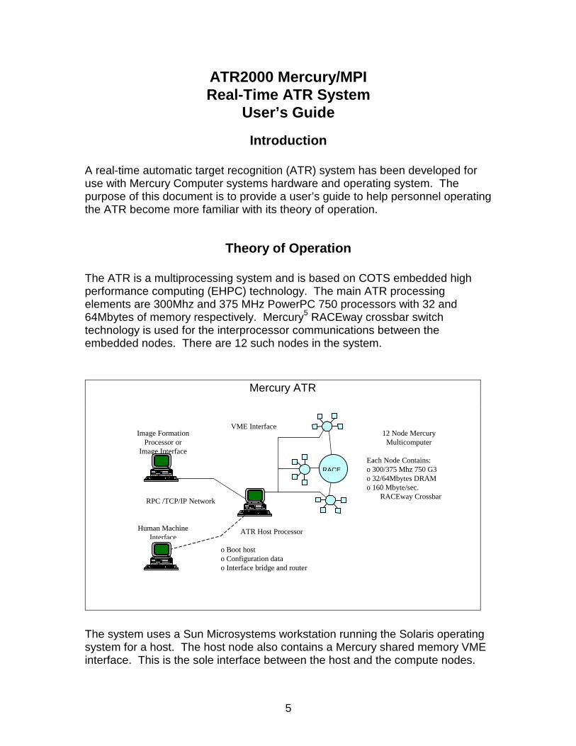
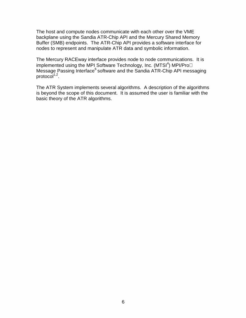
The ATR is a multiprocessing system and is based on COTS embedded highperformance computing (EHPC) technology. The main ATR processingelements are 300Mhz and 375 MHz PowerPC 750 processors with 32 and64Mbytes of memory respectively. Mercury5 RACEway crossbar switchtechnology is used for the interprocessor communications between theembedded nodes. There are 12 such nodes in the system.
The system uses a Sun Microsystems workstation running the Solaris operatingsystem for a host. The host node also contains a Mercury shared memory VMEinterface. This is the sole interface between the host and the compute nodes.
Mercury ATR
Image Formation
Processor or Image Interface
ATR Host Processor
o Boot host o Configuration data o Interface bridge and router
Human Machine Interface
RPC /TCP/IP Network
12 Node Mercury Multicomputer
Each Node Contains: o 300/375 Mhz 750 G3 o 32/64Mbytes DRAM o 160 Mbyte/sec.
RACEway Crossbar
RACE
VME Interface
6
The host and compute nodes communicate with each other over the VMEbackplane using the Sandia ATR-Chip API and the Mercury Shared MemoryBuffer (SMB) endpoints. The ATR-Chip API provides a software interface fornodes to represent and manipulate ATR data and symbolic information.
The Mercury RACEway interface provides node to node communications. It isimplemented using the MPI Software Technology, Inc. (MTSI4) MPI/ProMessage Passing Interface6 software and the Sandia ATR-Chip API messagingprotocol1,2.
The ATR System implements several algorithms. A description of the algorithmsis beyond the scope of this document. It is assumed the user is familiar with thebasic theory of the ATR algorithms.
7
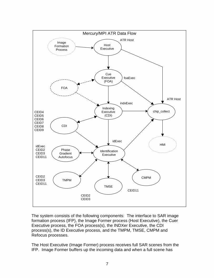
The system consists of the following components: The interface to SAR imageformation process (IFP), the Image Former process (Host Executive), the CuerExecutive process, the FOA process(s), the INDXer Executive, the CDIprocess(s), the ID Executive process, and the TMPM, TMSE, CMPM andRefocus processes.
The Host Executive (Image Former) process receives full SAR scenes from theIFP. Image Former buffers up the incoming data and when a full scene has
Mercury/MPI ATR Data Flow
ImageFormationProcess
HostExecutive
CueExecutive
(FOA)
IndexingExecutive
(CDI)
IdentificationExecutive
CMPMTMPM
PhaseGradient
Autofocus
TMSE
HMI
ATR Host
foaExec
indxExec
CEID11
idExecCEID2CEID3CEID11
idExec
CEID2CEID3CEID11
CEID2CEID3
chip_collect
ATR Host
FOA
CDI
CEID4CEID5CEID6CEID7CEID8CEID9
8
been acquired, it transmits the image to the FOA Executive. The Host Executivealso has the ability to break very large scenes up into overlapping sub-scenes.The sub-scenes are overlapped so as not to cut a potential target into twopieces. If sub-scenes are formed they are transmitted individually to the FOAExecutive node and are treated as separate images until the results are re-combined by the "chip_collect" process. At this time, duplicate ATR chip resultsare possible in the overlapping portion of the sub-scenes. The Image Formerprocess also sends a message (i.e. number of sub-scenes) to tell the"chip_collect" process that an image has arrived and is being sent to the ATR.
The FOA Executive process receives scenes (or sub-scenes), breaks them intosub-images, and sends the sub-images to a specified number of nodes, whichare executing the FOA process. Again, the sub-images are overlapped so as notto cut a potential target into two pieces Note the FOA Executive executes theFOA algorithm and it sends the full scene to the INDX Executive. The FOAExecutive also reports the number of sub-images it created to the "chip_collect"process.
Each FOA node performs the FOA algorithm on a sub-image and sends the FOAresults to the INDX Executive. The number of nodes running the FOA process isdetermined by the expected workload of the system (i.e. input pixel rate) and isconfigured by the system architect. Each FOA node gets a sub-image and theyoperate in parallel.
The INDX Executive receives the SAR scene (or sub-scene) and ATR resultsfrom each of the FOA process(s). It buffers ATR results until the sub-scenecomponents have been received. This buffering is due to the single-pipednature of the MPI communication model. It can cause a communicationbottleneck and is an area that should be examined in future architectures. Afterall results for a sub-image have been received, the INDX Executive chips out theregions of interest as determined by FOA results; and routes the ATR chips tothe CDI node(s). Again, the number of nodes running the CDI process isdetermined by the expected workload of the system (i.e. input pixel rate, imagecomplexity, etc.) and is configured by the system architect. ATR chips aredivided among available CDI nodes and they operate in parallel.
The ATR chips, which pass the CDI algorithm, are communicated to the IDExecutive process.
ATR chips results that fail the CDI algorithm are sent, via the INDX Executive, tothe "chip_collect" process on the ATR Host. Also, the total number of ATR chipscreated per image is sent to the "chip_collect" process.
In earlier implementations, the Cuer(FOA) and Indexer(SLD) processes werecombined into a single process on the same processing nodes; and FOA/SLDATR chips were routed directly to the MBV(ID) Executive process. However, the
9
current implementation separates the Cuer and Indexer functions on differentnodes. The new INDX algorithm (CDI) is more complex and requires moreprocessing power than the older Indexer (SLD).
The ID Executive receives the ATR results from each of the CDI process(s). Itbuffers ATR results until all CDI nodes have reported. This buffering is due tothe single-piped nature of the MPI communication model. It can cause acommunication bottleneck and is an area that should be examined in futurearchitectures.
Once the ID Executive receives ATR chips from the CDI processes, it routes thechips to the identification (ID) algorithms TMPM, TMSE and CMPM. Each chipdoes not necessarily get routed to each identification algorithm. The IDExecutive performs some executive control logic which combines the results ofall the ID algorithms into a single ID score, the TMD score. In order for a chip tobe declared as containing a target, the combined TMD score of all algorithmsmust be lower than a given threshold. If at any point a chip’s combined scoregrows greater than a given intermediate threshold, the target cue is declared anon-target and the cue is no longer processed and is forwarded to the ATR Host"chip_collect" process.
On the ATR Host, the "chip_collect" process queues the ATR chips for eachSAR scene sent to the ATR system. ATR chips are buffered until all results forevery scene are accounted for; then the entire chip list is transmitted to the HMIfor operator viewing. Multiple SAR scene results may be queued on the"chip_collect" at any one time (currently a maximum of 5 scenes). Note theactual SAR image data is currently not stored in the "chip_collect" process; itmust be transmitted directly from the SAR image formation processor (IFP) tothe HMI.
The system architect, for a given set of conditions determines the number ofnodes contained in an implementation of an ATR system. There can be multipleinstances of any given process. All data flow for the system is specified inconfiguration files. An example description of configuration files can be found inAppendix B:.
10
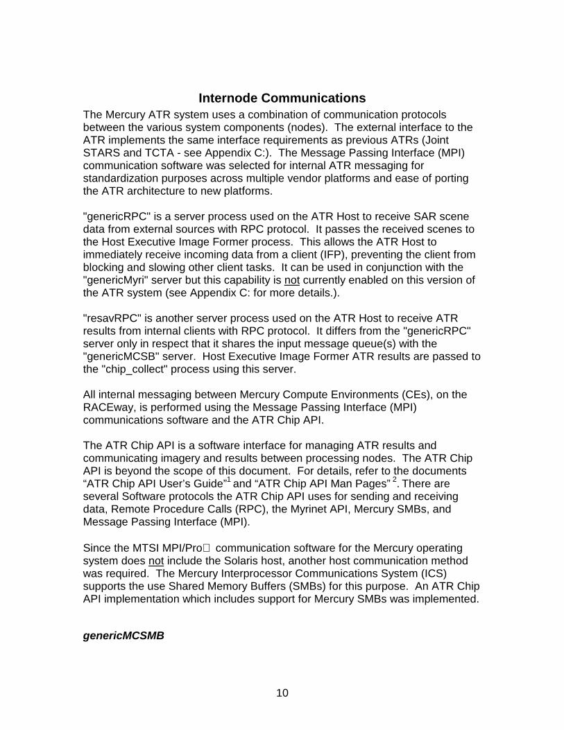
Internode CommunicationsThe Mercury ATR system uses a combination of communication protocolsbetween the various system components (nodes). The external interface to theATR implements the same interface requirements as previous ATRs (JointSTARS and TCTA - see Appendix C:). The Message Passing Interface (MPI)communication software was selected for internal ATR messaging forstandardization purposes across multiple vendor platforms and ease of portingthe ATR architecture to new platforms.
"genericRPC" is a server process used on the ATR Host to receive SAR scenedata from external sources with RPC protocol. It passes the received scenes tothe Host Executive Image Former process. This allows the ATR Host toimmediately receive incoming data from a client (IFP), preventing the client fromblocking and slowing other client tasks. It can be used in conjunction with the"genericMyri" server but this capability is not currently enabled on this version ofthe ATR system (see Appendix C: for more details.).
"resavRPC" is another server process used on the ATR Host to receive ATRresults from internal clients with RPC protocol. It differs from the "genericRPC"server only in respect that it shares the input message queue(s) with the"genericMCSB" server. Host Executive Image Former ATR results are passed tothe "chip_collect" process using this server.
All internal messaging between Mercury Compute Environments (CEs), on theRACEway, is performed using the Message Passing Interface (MPI)communications software and the ATR Chip API.
The ATR Chip API is a software interface for managing ATR results andcommunicating imagery and results between processing nodes. The ATR ChipAPI is beyond the scope of this document. For details, refer to the documents“ATR Chip API User’s Guide”1 and “ATR Chip API Man Pages” 2. There areseveral Software protocols the ATR Chip API uses for sending and receivingdata, Remote Procedure Calls (RPC), the Myrinet API, Mercury SMBs, andMessage Passing Interface (MPI).
Since the MTSI MPI/Pro communication software for the Mercury operatingsystem does not include the Solaris host, another host communication methodwas required. The Mercury Interprocessor Communications System (ICS)supports the use Shared Memory Buffers (SMBs) for this purpose. An ATR ChipAPI implementation which includes support for Mercury SMBs was implemented.
genericMCSMB
11
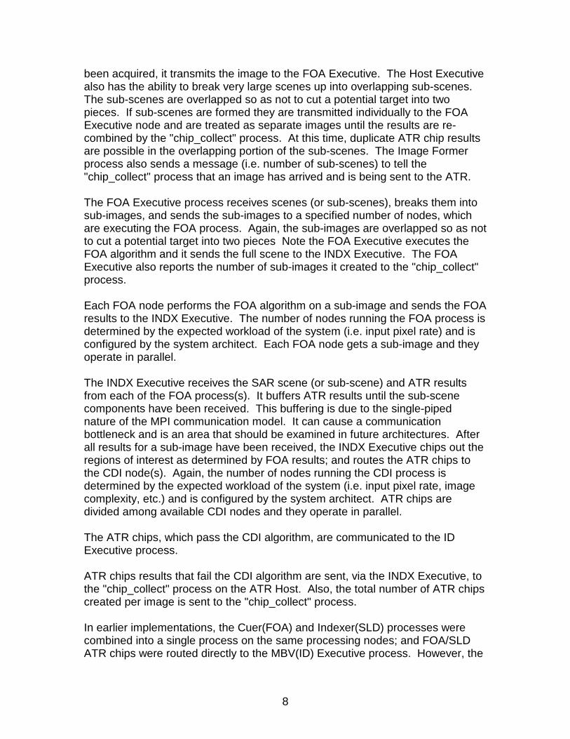
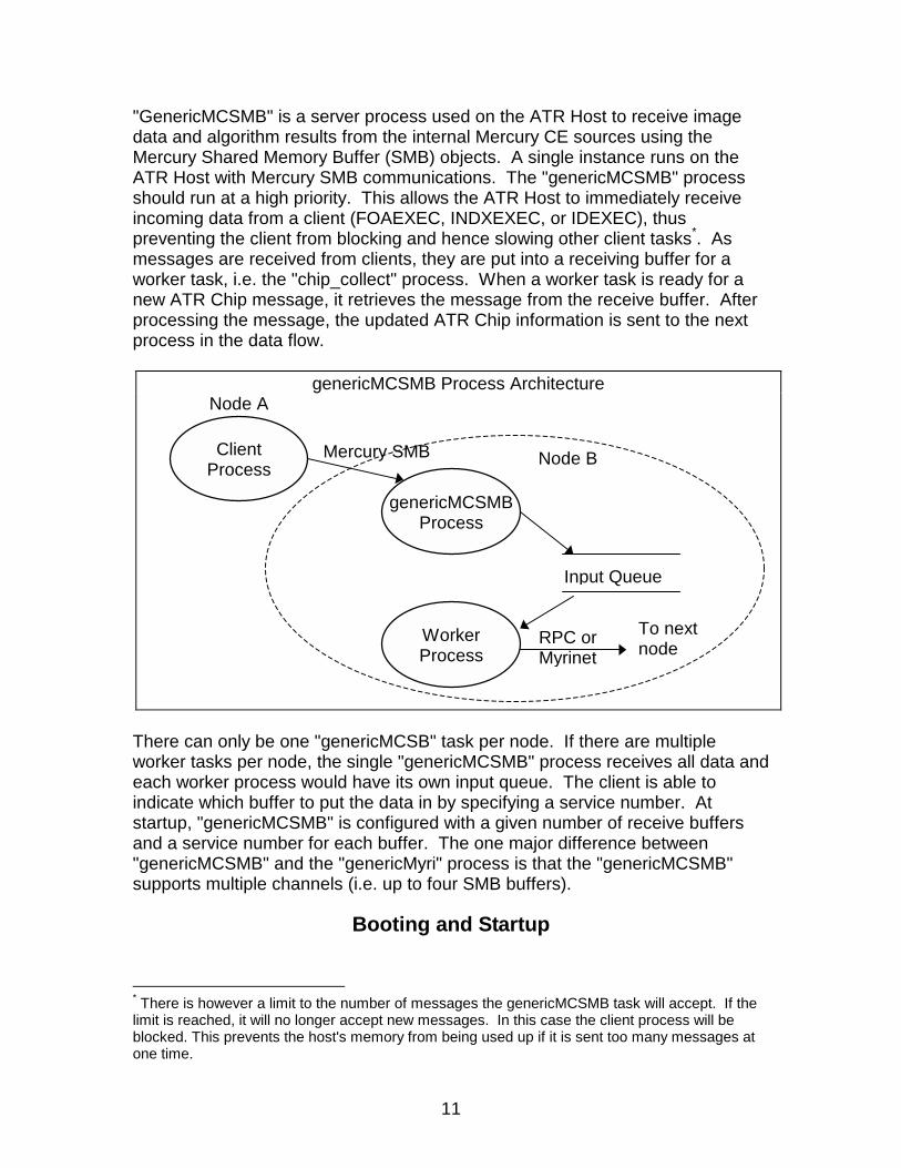
"GenericMCSMB" is a server process used on the ATR Host to receive imagedata and algorithm results from the internal Mercury CE sources using theMercury Shared Memory Buffer (SMB) objects. A single instance runs on theATR Host with Mercury SMB communications. The "genericMCSMB" processshould run at a high priority. This allows the ATR Host to immediately receiveincoming data from a client (FOAEXEC, INDXEXEC, or IDEXEC), thuspreventing the client from blocking and hence slowing other client tasks*. Asmessages are received from clients, they are put into a receiving buffer for aworker task, i.e. the "chip_collect" process. When a worker task is ready for anew ATR Chip message, it retrieves the message from the receive buffer. Afterprocessing the message, the updated ATR Chip information is sent to the nextprocess in the data flow.
There can only be one "genericMCSB" task per node. If there are multipleworker tasks per node, the single "genericMCSMB" process receives all data andeach worker process would have its own input queue. The client is able toindicate which buffer to put the data in by specifying a service number. Atstartup, "genericMCSMB" is configured with a given number of receive buffersand a service number for each buffer. The one major difference between"genericMCSMB" and the "genericMyri" process is that the "genericMCSMB"supports multiple channels (i.e. up to four SMB buffers).
Booting and Startup
* There is however a limit to the number of messages the genericMCSMB task will accept. If thelimit is reached, it will no longer accept new messages. In this case the client process will beblocked. This prevents the host's memory from being used up if it is sent too many messages atone time.
genericMCSMB Process Architecture
genericMCSMBProcess
WorkerProcess
Input Queue
ClientProcess
To nextnode
Mercury SMB
Node A
RPC orMyrinet
Node B
12
The workstation serves as the host for the entire ATR system. It provides forinitialization (booting CEs) and file system services. To bootstrap the entire ATRtake the following steps:
1. Power up the ATR VME chassis and the host workstation.
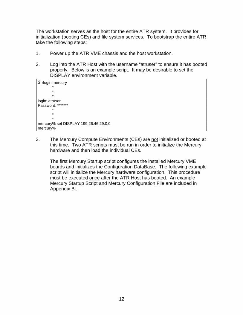
2. Log into the ATR Host with the username “atruser” to ensure it has bootedproperly. Below is an example script. It may be desirable to set theDISPLAY environment variable.
3. The Mercury Compute Environments (CEs) are not initialized or booted atthis time. Two ATR scripts must be run in order to initialize the Mercuryhardware and then load the individual CEs.
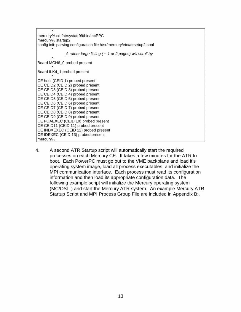
The first Mercury Startup script configures the installed Mercury VMEboards and initializes the Configuration DataBase. The following examplescript will initialize the Mercury hardware configuration. This proceduremust be executed once after the ATR Host has booted. An exampleMercury Startup Script and Mercury Configuration File are included inAppendix B:.
$ rlogin mercury***
login: atruserPassword: *******
***
mercury% set DISPLAY 199.26.46.29:0.0mercury%
13
4. A second ATR Startup script will automatically start the requiredprocesses on each Mercury CE. It takes a few minutes for the ATR toboot. Each PowerPC must go out to the VME backplane and load it’soperating system image, load all process executables, and initialize theMPI communication interface. Each process must read its configurationinformation and then load its appropriate configuration data. Thefollowing example script will initialize the Mercury operating system(MC/OS ) and start the Mercury ATR system. An example Mercury ATRStartup Script and MPI Process Group File are included in Appendix B:.
*mercury% cd /atrsys/atr99/bin/mcPPCmercury% startup2config init: parsing configuration file /usr/mercury/etc/atrsetup2.conf
*A rather large listing ( ~ 1 or 2 pages) will scroll by
*Board MCH6_0 probed present
*Board ILK4_1 probed present
*CE host (CEID 1) probed presentCE CEID2 (CEID 2) probed presentCE CEID3 (CEID 3) probed presentCE CEID4 (CEID 4) probed presentCE CEID5 (CEID 5) probed presentCE CEID6 (CEID 6) probed presentCE CEID7 (CEID 7) probed presentCE CEID8 (CEID 8) probed presentCE CEID9 (CEID 9) probed presentCE FOAEXEC (CEID 10) probed presentCE CEID11 (CEID 11) probed presentCE INDXEXEC (CEID 12) probed presentCE IDEXEC (CEID 13) probed presentmercury%
14
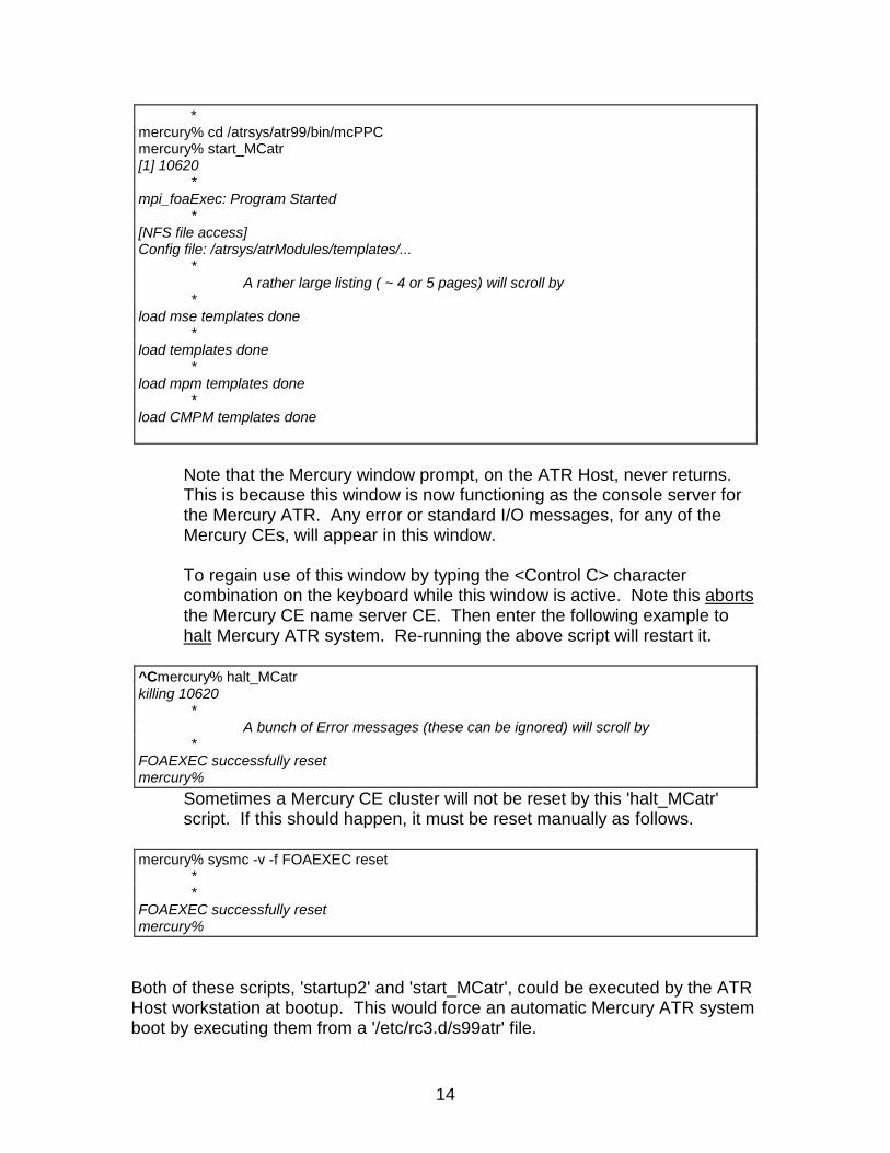
Note that the Mercury window prompt, on the ATR Host, never returns.This is because this window is now functioning as the console server forthe Mercury ATR. Any error or standard I/O messages, for any of theMercury CEs, will appear in this window.
To regain use of this window by typing the <Control C> charactercombination on the keyboard while this window is active. Note this abortsthe Mercury CE name server CE. Then enter the following example tohalt Mercury ATR system. Re-running the above script will restart it.
Sometimes a Mercury CE cluster will not be reset by this 'halt_MCatr'script. If this should happen, it must be reset manually as follows.
Both of these scripts, 'startup2' and 'start_MCatr', could be executed by the ATRHost workstation at bootup. This would force an automatic Mercury ATR systemboot by executing them from a '/etc/rc3.d/s99atr' file.
*mercury% cd /atrsys/atr99/bin/mcPPCmercury% start_MCatr[1] 10620
*mpi_foaExec: Program Started
*[NFS file access]Config file: /atrsys/atrModules/templates/...
*A rather large listing ( ~ 4 or 5 pages) will scroll by
*load mse templates done
*load templates done
*load mpm templates done
*load CMPM templates done
^Cmercury% halt_MCatrkilling 10620
*A bunch of Error messages (these can be ignored) will scroll by
*FOAEXEC successfully resetmercury%
mercury% sysmc -v -f FOAEXEC reset**
FOAEXEC successfully resetmercury%
15
The best indication of the ATR state is to monitor the console server bootmessages and wait for all configuration templates to be loaded. This alsodisplays any error messages that may have occurred.
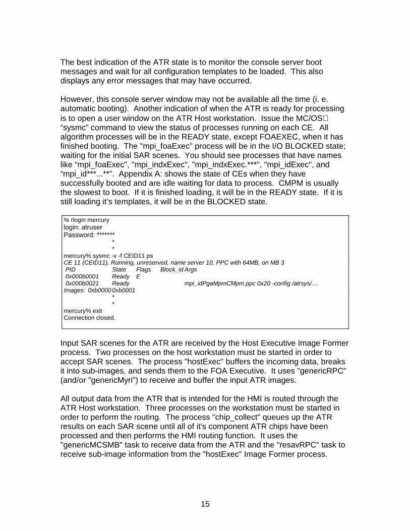
However, this console server window may not be available all the time (i. e.automatic booting). Another indication of when the ATR is ready for processingis to open a user window on the ATR Host workstation. Issue the MC/OS“sysmc” command to view the status of processes running on each CE. Allalgorithm processes will be in the READY state, except FOAEXEC, when it hasfinished booting. The "mpi_foaExec" process will be in the I/O BLOCKED state;waiting for the initial SAR scenes. You should see processes that have nameslike “mpi_foaExec", "mpi_indxExec", "mpi_indxExec.***", "mpi_idExec", and“mpi_id***...**”. Appendix A: shows the state of CEs when they havesuccessfully booted and are idle waiting for data to process. CMPM is usuallythe slowest to boot. If it is finished loading, it will be in the READY state. If it isstill loading it’s templates, it will be in the BLOCKED state.
Input SAR scenes for the ATR are received by the Host Executive Image Formerprocess. Two processes on the host workstation must be started in order toaccept SAR scenes. The process "hostExec" buffers the incoming data, breaksit into sub-images, and sends them to the FOA Executive. It uses "genericRPC"(and/or "genericMyri") to receive and buffer the input ATR images.
All output data from the ATR that is intended for the HMI is routed through theATR Host workstation. Three processes on the workstation must be started inorder to perform the routing. The process "chip_collect" queues up the ATRresults on each SAR scene until all of it's component ATR chips have beenprocessed and then performs the HMI routing function. It uses the"genericMCSMB" task to receive data from the ATR and the "resavRPC" task toreceive sub-image information from the "hostExec" Image Former process.
% rlogin mercurylogin: atruserPassword: *******
**
mercury% sysmc -v -f CEID11 psCE 11 (CEID11), Running, unreserved, name server 10, PPC with 64MB, on MB 3 PID State Flags Block_id Args 0x000b0001 Ready E 0x000b0021 Ready mpi_idPgaMpmCMpm.ppc 0x20 -config /atrsys/....Images: 0xb00000xb0001
**
mercury% exitConnection closed.
16
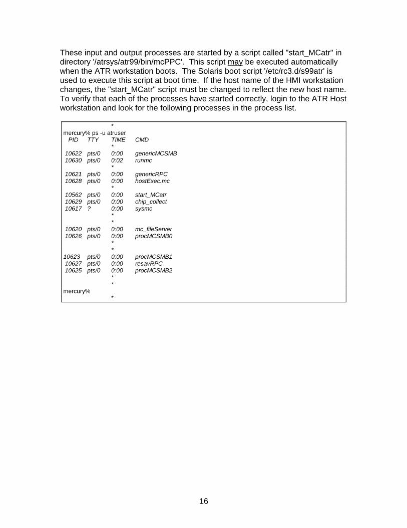
These input and output processes are started by a script called "start_MCatr" indirectory '/atrsys/atr99/bin/mcPPC'. This script may be executed automaticallywhen the ATR workstation boots. The Solaris boot script '/etc/rc3.d/s99atr' isused to execute this script at boot time. If the host name of the HMI workstationchanges, the "start_MCatr" script must be changed to reflect the new host name.To verify that each of the processes have started correctly, login to the ATR Hostworkstation and look for the following processes in the process list.
*mercury% ps -u atruser PID TTY TIME CMD
* 10622 pts/0 0:00 genericMCSMB 10630 pts/0 0:02 runmc
* 10621 pts/0 0:00 genericRPC 10628 pts/0 0:00 hostExec.mc
* 10562 pts/0 0:00 start_MCatr 10629 pts/0 0:00 chip_collect 10617 ? 0:00 sysmc
**
10620 pts/0 0:00 mc_fileServer 10626 pts/0 0:00 procMCSMB0
**
10623 pts/0 0:00 procMCSMB1 10627 pts/0 0:00 resavRPC 10625 pts/0 0:00 procMCSMB2
**
mercury%*

17
At this point, the system is ready to receive images from the IFP.
Note that both the Image Formation Process (i.e. dhs) and the HMI Displayprocess must be started independently. Each of these functions are separateoperations from the ATR; and may consist of very diverse procedures ondifferent hardware systems. A description of their operation is beyond the scopeof this document but the interface requirements are included in Appendix C:.
18
Getting to Know Your Way Around
There are a total of 12 PowerPC processors comprising the Mercury ATRsystem. The PowerPC processors run the MC/OS real-time operating system,and the ATR workstation processor runs Sun Microsystems Solaris (a Unixvariant) operating system. It is not necessary for the user to be familiar withthese operating systems, but if the user wants to check the state of theprocesses and trouble shoot the system, basic knowledge of the Unix andMercury Operating System MC/OS environment is required.
Unfortunately, the MC/OS operating system is not as flexible as some otherreal-time operating systems. In terms of allowing a user to examine internalprocess parameters from the command line, it is very limited. A source leveldebugger "gdbmc" is available for real-time operation; but it requires a high-levelof knowledge of the OS (and '-g' re-compilation). The most helpful MC/OSconsole server command is the “sysmc .. ps” command which prints out allprocesses presently loaded. Using the "sysmc" command it is possible to checkand make sure all processors have booted properly and that they have spawnedall the appropriate tasks. Appendix A: provides example sessions and executingthe “sysmc .. ps” command(s).
If the ATR is running correctly, it is not necessary to monitor its operation. If it isdesirable to monitor the ATR a little more closely, the verbose parameter "-v"flag(s) may be set to some value in the CEs invocation string. This is acommand line argument which is passed to each ATR process at it's invocation.Editing the verbose parameter '-v' in the Mercury ATR Startup Script (e.g."start_MCatr") file and/or the MPI Process Group File (e.g. "jstarsATR.pg") willset it to the desired value.
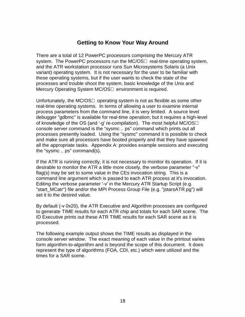
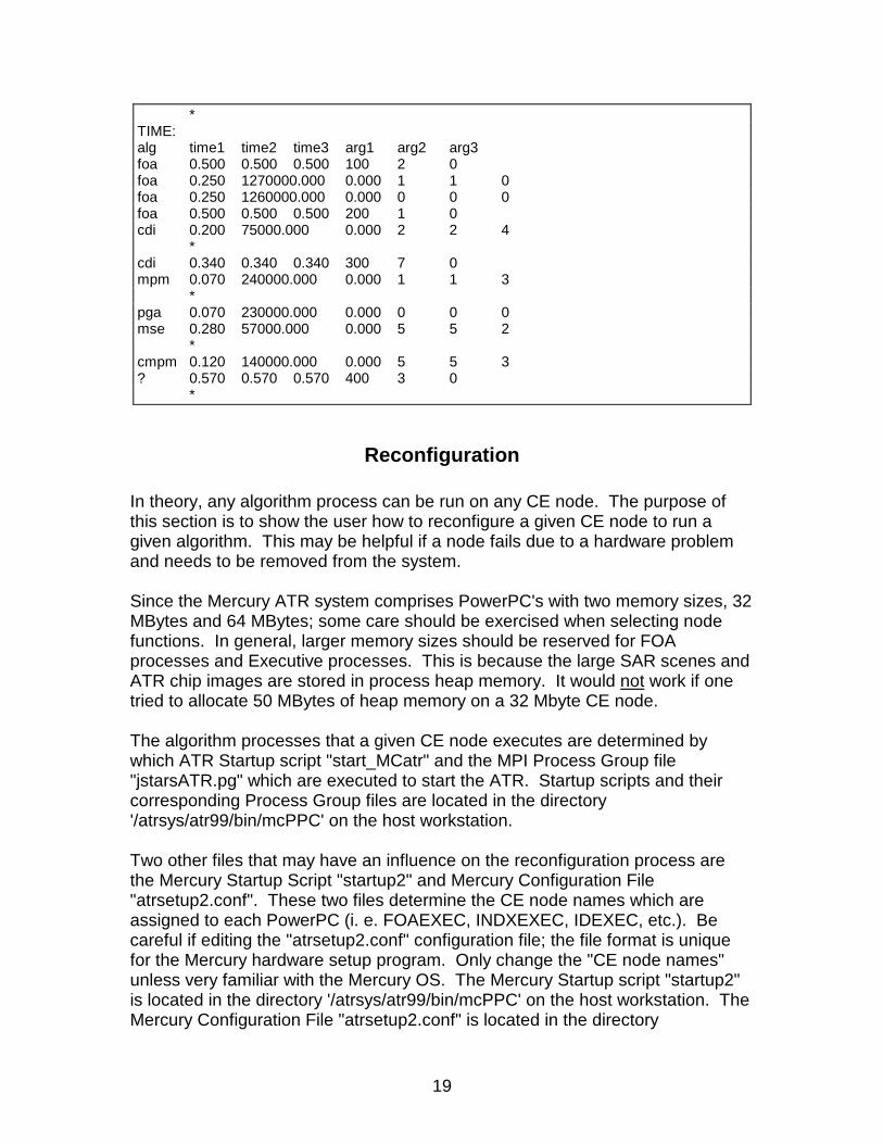
By default (-v 0x20), the ATR Executive and Algorithm processes are configuredto generate TIME results for each ATR chip and totals for each SAR scene. TheID Executive prints out these ATR TIME results for each SAR scene as it isprocessed.
The following example output shows the TIME results as displayed in theconsole server window. The exact meaning of each value in the printout variesform algorithm-to-algorithm and is beyond the scope of this document. It doesrepresent the type of algorithms (FOA, CDI, etc.) which were utilized and thetimes for a SAR scene.
19
Reconfiguration
In theory, any algorithm process can be run on any CE node. The purpose ofthis section is to show the user how to reconfigure a given CE node to run agiven algorithm. This may be helpful if a node fails due to a hardware problemand needs to be removed from the system.
Since the Mercury ATR system comprises PowerPC's with two memory sizes, 32MBytes and 64 MBytes; some care should be exercised when selecting nodefunctions. In general, larger memory sizes should be reserved for FOAprocesses and Executive processes. This is because the large SAR scenes andATR chip images are stored in process heap memory. It would not work if onetried to allocate 50 MBytes of heap memory on a 32 Mbyte CE node.
The algorithm processes that a given CE node executes are determined bywhich ATR Startup script "start_MCatr" and the MPI Process Group file"jstarsATR.pg" which are executed to start the ATR. Startup scripts and theircorresponding Process Group files are located in the directory'/atrsys/atr99/bin/mcPPC' on the host workstation.
Two other files that may have an influence on the reconfiguration process arethe Mercury Startup Script "startup2" and Mercury Configuration File"atrsetup2.conf". These two files determine the CE node names which areassigned to each PowerPC (i. e. FOAEXEC, INDXEXEC, IDEXEC, etc.). Becareful if editing the "atrsetup2.conf" configuration file; the file format is uniquefor the Mercury hardware setup program. Only change the "CE node names"unless very familiar with the Mercury OS. The Mercury Startup script "startup2"is located in the directory '/atrsys/atr99/bin/mcPPC' on the host workstation. TheMercury Configuration File "atrsetup2.conf" is located in the directory
*TIME:alg time1 time2 time3 arg1 arg2 arg3foa 0.500 0.500 0.500 100 2 0foa 0.250 1270000.000 0.000 1 1 0foa 0.250 1260000.000 0.000 0 0 0foa 0.500 0.500 0.500 200 1 0cdi 0.200 75000.000 0.000 2 2 4
*cdi 0.340 0.340 0.340 300 7 0mpm 0.070 240000.000 0.000 1 1 3
*pga 0.070 230000.000 0.000 0 0 0mse 0.280 57000.000 0.000 5 5 2
*cmpm 0.120 140000.000 0.000 5 5 3? 0.570 0.570 0.570 400 3 0
*
20
'/usr/mercury/etc' and you may need 'super-user' access' privileges in order tochange it.
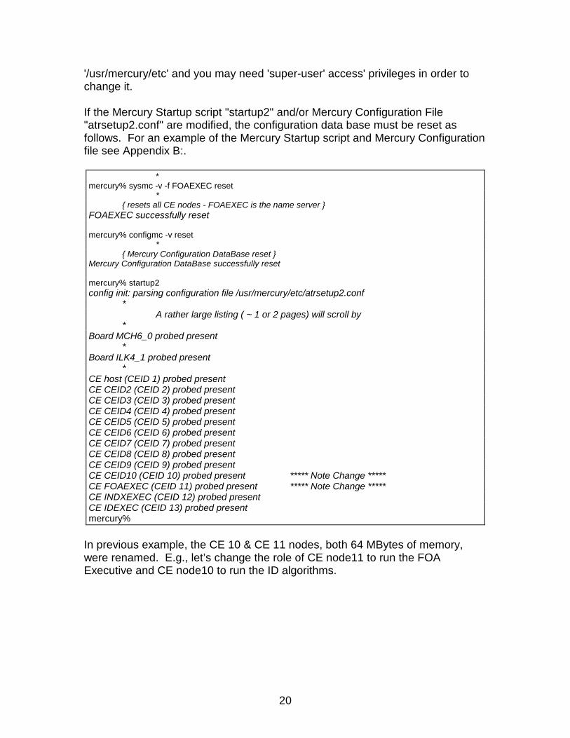
If the Mercury Startup script "startup2" and/or Mercury Configuration File"atrsetup2.conf" are modified, the configuration data base must be reset asfollows. For an example of the Mercury Startup script and Mercury Configurationfile see Appendix B:.
In previous example, the CE 10 & CE 11 nodes, both 64 MBytes of memory,were renamed. E.g., let’s change the role of CE node11 to run the FOAExecutive and CE node10 to run the ID algorithms.
*mercury% sysmc -v -f FOAEXEC reset
*{ resets all CE nodes - FOAEXEC is the name server }
FOAEXEC successfully reset
mercury% configmc -v reset*
{ Mercury Configuration DataBase reset }Mercury Configuration DataBase successfully reset
mercury% startup2config init: parsing configuration file /usr/mercury/etc/atrsetup2.conf
*A rather large listing ( ~ 1 or 2 pages) will scroll by
*Board MCH6_0 probed present
*Board ILK4_1 probed present
*CE host (CEID 1) probed presentCE CEID2 (CEID 2) probed presentCE CEID3 (CEID 3) probed presentCE CEID4 (CEID 4) probed presentCE CEID5 (CEID 5) probed presentCE CEID6 (CEID 6) probed presentCE CEID7 (CEID 7) probed presentCE CEID8 (CEID 8) probed presentCE CEID9 (CEID 9) probed presentCE CEID10 (CEID 10) probed present ***** Note Change *****CE FOAEXEC (CEID 11) probed present ***** Note Change *****CE INDXEXEC (CEID 12) probed presentCE IDEXEC (CEID 13) probed presentmercury%
21
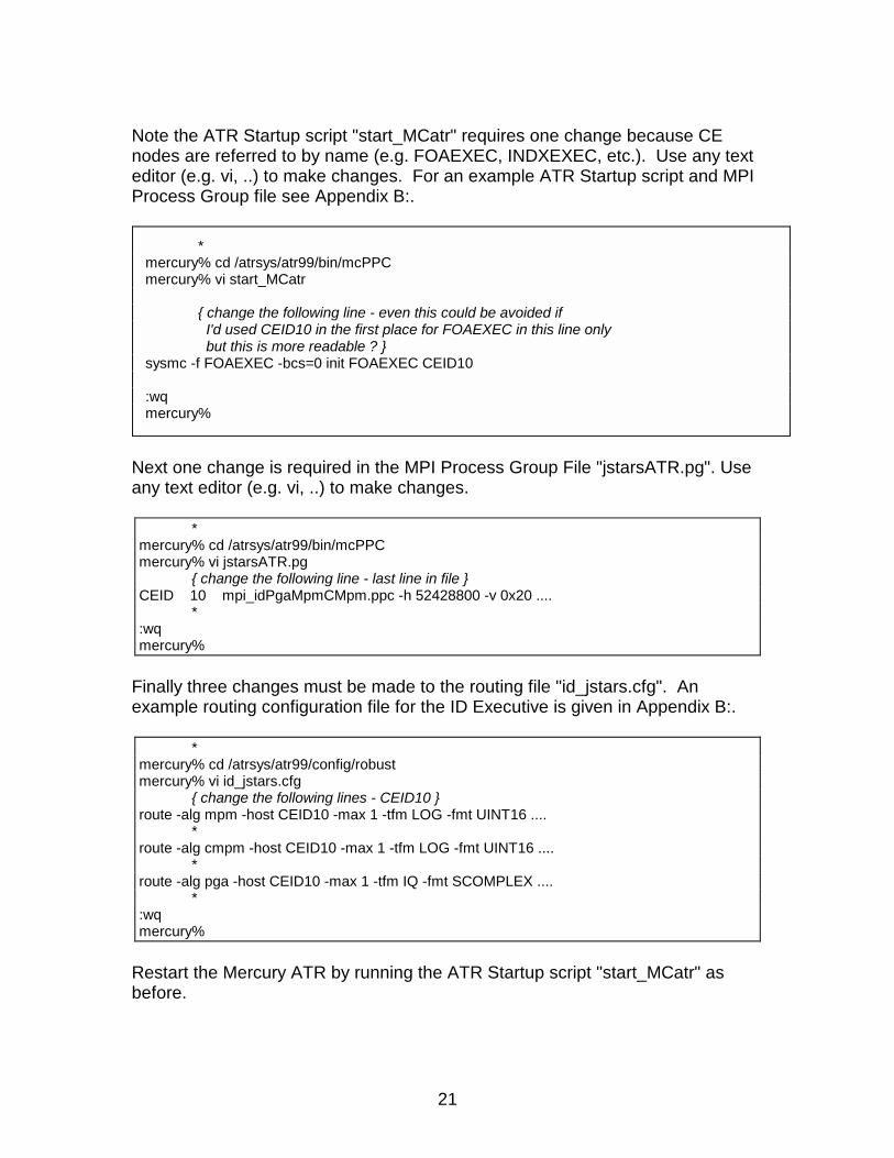
Note the ATR Startup script "start_MCatr" requires one change because CEnodes are referred to by name (e.g. FOAEXEC, INDXEXEC, etc.). Use any texteditor (e.g. vi, ..) to make changes. For an example ATR Startup script and MPIProcess Group file see Appendix B:.
Next one change is required in the MPI Process Group File "jstarsATR.pg". Useany text editor (e.g. vi, ..) to make changes.
Finally three changes must be made to the routing file "id_jstars.cfg". Anexample routing configuration file for the ID Executive is given in Appendix B:.
Restart the Mercury ATR by running the ATR Startup script "start_MCatr" asbefore.
*mercury% cd /atrsys/atr99/bin/mcPPCmercury% vi start_MCatr
{ change the following line - even this could be avoided if I'd used CEID10 in the first place for FOAEXEC in this line only but this is more readable ? }
sysmc -f FOAEXEC -bcs=0 init FOAEXEC CEID10
:wqmercury%
*mercury% cd /atrsys/atr99/bin/mcPPCmercury% vi jstarsATR.pg
{ change the following line - last line in file }CEID 10 mpi_idPgaMpmCMpm.ppc -h 52428800 -v 0x20 ....
*:wqmercury%
*mercury% cd /atrsys/atr99/config/robustmercury% vi id_jstars.cfg
{ change the following lines - CEID10 }route -alg mpm -host CEID10 -max 1 -tfm LOG -fmt UINT16 ....
*route -alg cmpm -host CEID10 -max 1 -tfm LOG -fmt UINT16 ....
*route -alg pga -host CEID10 -max 1 -tfm IQ -fmt SCOMPLEX ....
*:wqmercury%
22
Note this reconfiguration example was one of the most difficult possible becauseit involved PowerPC module name changes. However, it did take us through allthe possible reconfiguration steps. Many CE node changes require onlychanges to the MPI Process Group file "jstarsATR.pg" and/or the routing file"id_jstars.cfg".
Verbose Control Parameters
In terms of allowing a user to examine internal process parameters from thecommand line, the MC/OS operating system is very limited. A source leveldebugger "gdbmc" is available for real-time operation; but it requires a high-levelof knowledge of the OS ( '-g' re-compilation) and may alter the program flow.The previously mentioned "sysmc" command ( see Appendix A:) is the onlyavailable runtime command.
Unlike previous ATR versions, individual process parameters are not availablefrom the VxWorks shell command line. To compensate for this lack of internalparameter visibility, an extensive set of verbose ( -v ) option flag settings areincluded within the process modules. These verbose flags are set at programinitialization (boot time) by the ATR Startup script "start_MCatr" and the MPIProcess Group file "jstarsATR.pg" (see Appendix B:). They are intended for de-bugging purposes and not as general user commands.
The core of the ATR system is the FOA, INDX, and ID Executives through withall of the ATR images must pass. This Executive(s) software takes care ofrouting chips to nodes. The difference between the FOA/INDX Executive(s) andID Executive is in the scoring software that determines routing for the IDExecutive. The FOA and INDX Executive have simple routing scheme(s), butthe ID Executive is more complicated because it has to combine the results ofthe various identification stage algorithms. These Executive nodes are the firstto places to examine when trying to understand or trouble-shoot ATR problems.
When a certain verbose (-v 0x01) flag is set, information on a specific topic isdisplayed in the console server window for that CE node. A high-levelknowledge of internal ATR process operation may be required to understand thisprintout. This verbose capability is here for anyone who may have a more in-depth understanding of the ATR operations.
Each CE node in the Mercury ATR system has it's own verbose flag and thevarious options may be bit-wise OR'ed together. Because all the verboseinformation is displayed on one console server window, the verbose flag forindividual CEs are usually set singularly (or in pairs). This prevents a flood ofincomprehensible information scrolling across the screen from separate CEnodes.
23
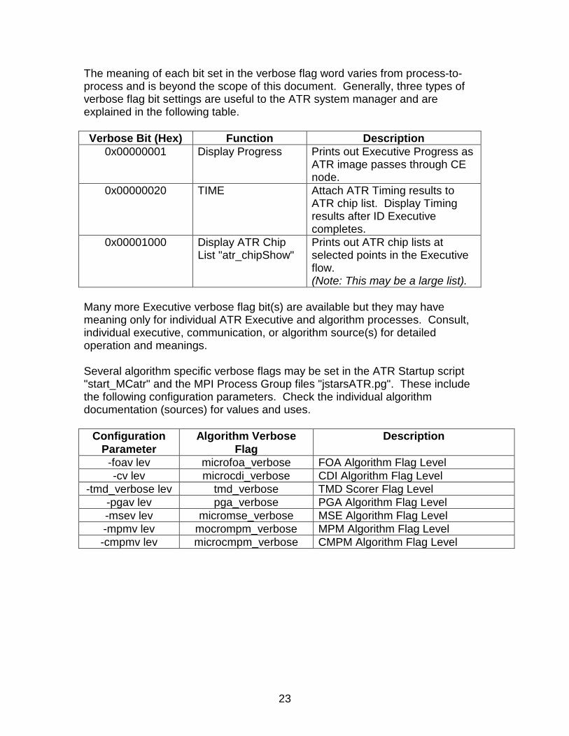
The meaning of each bit set in the verbose flag word varies from process-to-process and is beyond the scope of this document. Generally, three types ofverbose flag bit settings are useful to the ATR system manager and areexplained in the following table.
Verbose Bit (Hex) Function Description0x00000001 Display Progress Prints out Executive Progress as
ATR image passes through CEnode.
0x00000020 TIME Attach ATR Timing results toATR chip list. Display Timingresults after ID Executivecompletes.
0x00001000 Display ATR ChipList "atr_chipShow"
Prints out ATR chip lists atselected points in the Executiveflow.(Note: This may be a large list).
Many more Executive verbose flag bit(s) are available but they may havemeaning only for individual ATR Executive and algorithm processes. Consult,individual executive, communication, or algorithm source(s) for detailedoperation and meanings.
Several algorithm specific verbose flags may be set in the ATR Startup script"start_MCatr" and the MPI Process Group files "jstarsATR.pg". These includethe following configuration parameters. Check the individual algorithmdocumentation (sources) for values and uses.
ConfigurationParameter
Algorithm VerboseFlag
Description
-foav lev microfoa_verbose FOA Algorithm Flag Level-cv lev microcdi_verbose CDI Algorithm Flag Level
-tmd_verbose lev tmd_verbose TMD Scorer Flag Level-pgav lev pga_verbose PGA Algorithm Flag Level-msev lev micromse_verbose MSE Algorithm Flag Level-mpmv lev mocrompm_verbose MPM Algorithm Flag Level-cmpmv lev microcmpm_verbose CMPM Algorithm Flag Level
24
The Boot Process
The most critical procedure for the ATR is the boot process. If a node fails, itmost likely will occur at boot and/or program initialization.
The best indication of the ATR state is to monitor the console server bootmessages and wait for all configuration templates to be loaded. This alsodisplays any error messages that may have occurred.
At power-up all the Mercury Compute Environment (CE) VME boards will displaytwo yellow LEDs (PRC1 and PRC2) as the normal reset mode.
As the compute nodes are initialized (i.e. "sysmc ... init"), the yellow LEDsextinguish and green LEDs (processors A, B, C, and D) flash depending onwhich CE processor is being loaded. Also, the yellow (orange) VME LEDindicates VME backplane activity. When all CEs are loaded and initialized, thegreen front panel LEDs will extinguish (turn OFF) except for bursts of monitoringactivity.
At this point, the green LEDs are functioning as an activity indicator for each CEnode. A special CE processor (e.g. currently CE 10) is designated as theMercury name server node and may show more activity than the other nodes.During periods of SAR scene downloading, the FOAEXEC (i.e. CE 10) willindicate significant VME bus activity.
If an error is detected or a required process(s) dies, the Error message will bedisplayed in the Console Server window.
Pressing the "Reset" button on the front panel of the any Mercury VME board willreset the individual board. However, if any board is reset the whole ATR systemwill need to be halted and re-initialized (see Booting and Startup, section 4).
25
References1. D. W. Doerfler, ATR Chip API User's Manual, internal documentation in HTML
format, Sandia National Laboratories, Albuquerque, NM, version 10/00.2. D. W. Doerfler, ATR Chip API User's Man Pages, internal documentation in
HTML format, Sandia National Laboratories, Albuquerque, NM, version11/00.
3. http://www.myri.com, Myricom, Inc., Arcadia, CA.4. http://www.mpi-softtech.com, MPI Software Technology, Inc., Starkville, MS5. http://www.mc.com, Mercury Computer Systems, Inc., Chelmsford, MA6. M. Snir, S. Otto, S. Huss-Lederman, D. Walker, J. Dongarra, MPI: The
Complete Reference, The MIT Press, Cambridge, Massachusetts, 1996.
26
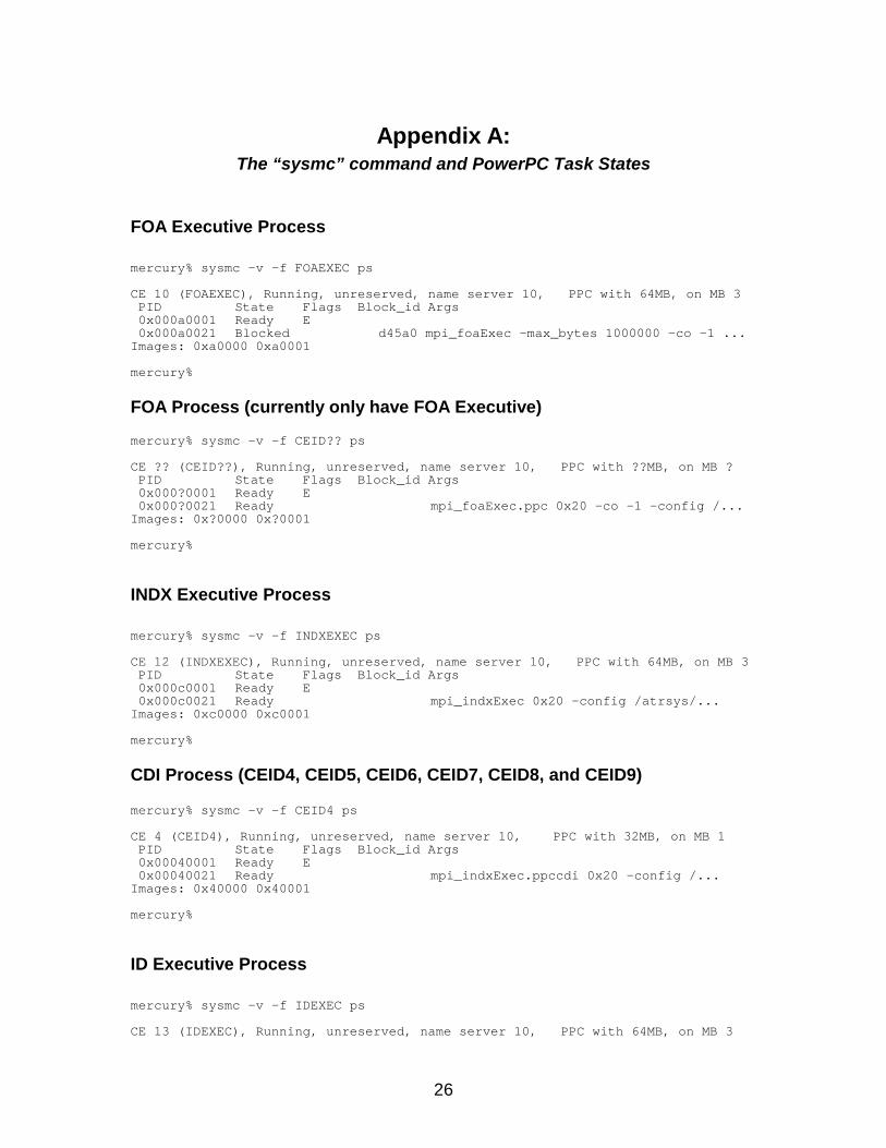
Appendix A:The “sysmc” command and PowerPC Task States
FOA Executive Process
mercury% sysmc -v -f FOAEXEC ps
CE 10 (FOAEXEC), Running, unreserved, name server 10, PPC with 64MB, on MB 3PID State Flags Block_id Args0x000a0001 Ready E0x000a0021 Blocked d45a0 mpi_foaExec -max_bytes 1000000 -co -1 ...
Images: 0xa0000 0xa0001
mercury%
FOA Process (currently only have FOA Executive)
mercury% sysmc -v -f CEID?? ps
CE ?? (CEID??), Running, unreserved, name server 10, PPC with ??MB, on MB ?PID State Flags Block_id Args0x000?0001 Ready E0x000?0021 Ready mpi_foaExec.ppc 0x20 -co -1 -config /...
Images: 0x?0000 0x?0001
mercury%
INDX Executive Process
mercury% sysmc -v -f INDXEXEC ps
CE 12 (INDXEXEC), Running, unreserved, name server 10, PPC with 64MB, on MB 3PID State Flags Block_id Args0x000c0001 Ready E0x000c0021 Ready mpi_indxExec 0x20 -config /atrsys/...
Images: 0xc0000 0xc0001
mercury%
CDI Process (CEID4, CEID5, CEID6, CEID7, CEID8, and CEID9)
mercury% sysmc -v -f CEID4 ps
CE 4 (CEID4), Running, unreserved, name server 10, PPC with 32MB, on MB 1PID State Flags Block_id Args0x00040001 Ready E0x00040021 Ready mpi_indxExec.ppccdi 0x20 -config /...
Images: 0x40000 0x40001
mercury%
ID Executive Process
mercury% sysmc -v -f IDEXEC ps
CE 13 (IDEXEC), Running, unreserved, name server 10, PPC with 64MB, on MB 3
27
PID State Flags Block_id Args0x000d0001 Ready E0x000d0021 Ready mpi_idExec 0x20 -indexer cdi -config /...
Images: 0xd0000 0xd0001
mercury%
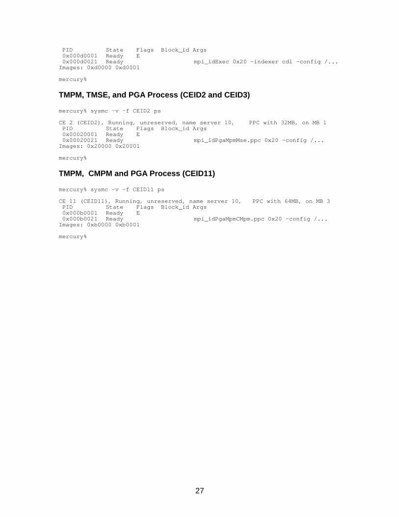
TMPM, TMSE, and PGA Process (CEID2 and CEID3)
mercury% sysmc -v -f CEID2 ps
CE 2 (CEID2), Running, unreserved, name server 10, PPC with 32MB, on MB 1PID State Flags Block_id Args0x00020001 Ready E0x00020021 Ready mpi_idPgaMpmMse.ppc 0x20 -config /...
Images: 0x20000 0x20001
mercury%
TMPM, CMPM and PGA Process (CEID11)
mercury% sysmc -v -f CEID11 ps
CE 11 (CEID11), Running, unreserved, name server 10, PPC with 64MB, on MB 3PID State Flags Block_id Args0x000b0001 Ready E0x000b0021 Ready mpi_idPgaMpmCMpm.ppc 0x20 -config /...
Images: 0xb0000 0xb0001
mercury%
28
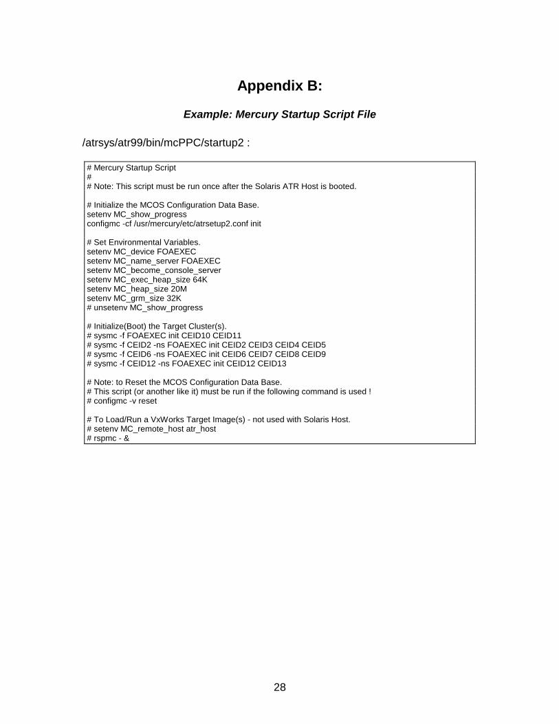
Appendix B:
Example: Mercury Startup Script File
/atrsys/atr99/bin/mcPPC/startup2 :
# Mercury Startup Script## Note: This script must be run once after the Solaris ATR Host is booted.
# Initialize the MCOS Configuration Data Base.setenv MC_show_progressconfigmc -cf /usr/mercury/etc/atrsetup2.conf init
# Set Environmental Variables.setenv MC_device FOAEXECsetenv MC_name_server FOAEXECsetenv MC_become_console_serversetenv MC_exec_heap_size 64Ksetenv MC_heap_size 20Msetenv MC_grm_size 32K# unsetenv MC_show_progress
# Initialize(Boot) the Target Cluster(s).# sysmc -f FOAEXEC init CEID10 CEID11# sysmc -f CEID2 -ns FOAEXEC init CEID2 CEID3 CEID4 CEID5# sysmc -f CEID6 -ns FOAEXEC init CEID6 CEID7 CEID8 CEID9# sysmc -f CEID12 -ns FOAEXEC init CEID12 CEID13
# Note: to Reset the MCOS Configuration Data Base.# This script (or another like it) must be run if the following command is used !# configmc -v reset
# To Load/Run a VxWorks Target Image(s) - not used with Solaris Host.# setenv MC_remote_host atr_host# rspmc - &
29
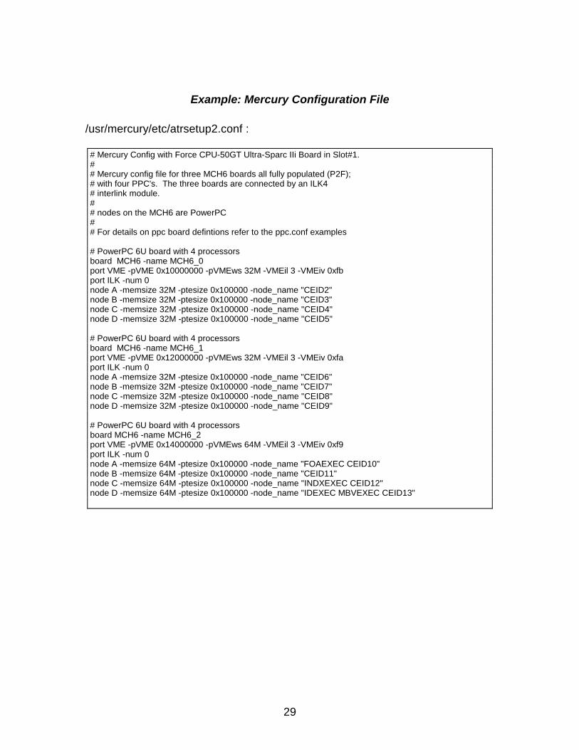
Example: Mercury Configuration File
/usr/mercury/etc/atrsetup2.conf :
# Mercury Config with Force CPU-50GT Ultra-Sparc IIi Board in Slot#1.## Mercury config file for three MCH6 boards all fully populated (P2F);# with four PPC's. The three boards are connected by an ILK4# interlink module.## nodes on the MCH6 are PowerPC## For details on ppc board defintions refer to the ppc.conf examples
# PowerPC 6U board with 4 processorsboard MCH6 -name MCH6_0port VME -pVME 0x10000000 -pVMEws 32M -VMEil 3 -VMEiv 0xfbport ILK -num 0node A -memsize 32M -ptesize 0x100000 -node_name "CEID2"node B -memsize 32M -ptesize 0x100000 -node_name "CEID3"node C -memsize 32M -ptesize 0x100000 -node_name "CEID4"node D -memsize 32M -ptesize 0x100000 -node_name "CEID5"
# PowerPC 6U board with 4 processorsboard MCH6 -name MCH6_1port VME -pVME 0x12000000 -pVMEws 32M -VMEil 3 -VMEiv 0xfaport ILK -num 0node A -memsize 32M -ptesize 0x100000 -node_name "CEID6"node B -memsize 32M -ptesize 0x100000 -node_name "CEID7"node C -memsize 32M -ptesize 0x100000 -node_name "CEID8"node D -memsize 32M -ptesize 0x100000 -node_name "CEID9"
# PowerPC 6U board with 4 processorsboard MCH6 -name MCH6_2port VME -pVME 0x14000000 -pVMEws 64M -VMEil 3 -VMEiv 0xf9port ILK -num 0node A -memsize 64M -ptesize 0x100000 -node_name "FOAEXEC CEID10"node B -memsize 64M -ptesize 0x100000 -node_name "CEID11"node C -memsize 64M -ptesize 0x100000 -node_name "INDXEXEC CEID12"node D -memsize 64M -ptesize 0x100000 -node_name "IDEXEC MBVEXEC CEID13"
30
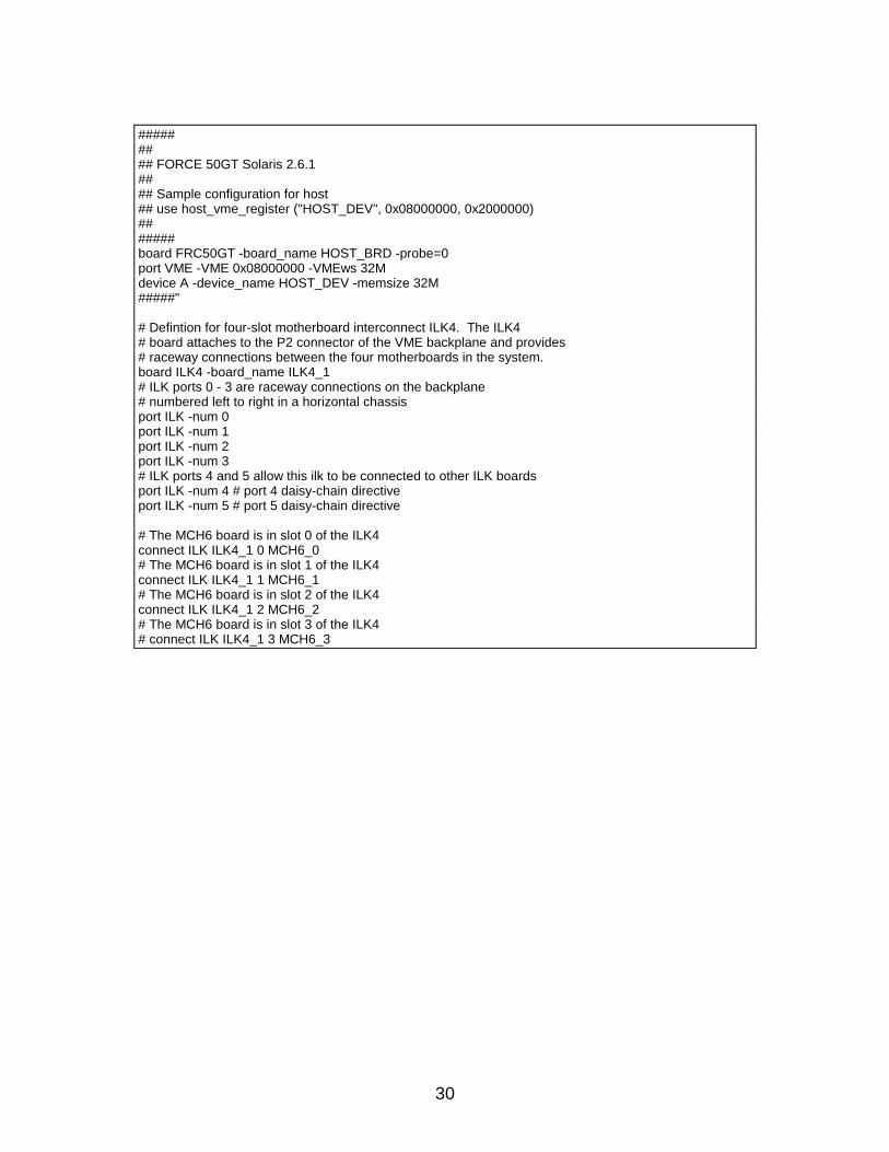
######### FORCE 50GT Solaris 2.6.1#### Sample configuration for host## use host_vme_register ("HOST_DEV", 0x08000000, 0x2000000)#######board FRC50GT -board_name HOST_BRD -probe=0port VME -VME 0x08000000 -VMEws 32Mdevice A -device_name HOST_DEV -memsize 32M#####"
# Defintion for four-slot motherboard interconnect ILK4. The ILK4# board attaches to the P2 connector of the VME backplane and provides# raceway connections between the four motherboards in the system.board ILK4 -board_name ILK4_1# ILK ports 0 - 3 are raceway connections on the backplane# numbered left to right in a horizontal chassisport ILK -num 0port ILK -num 1port ILK -num 2port ILK -num 3# ILK ports 4 and 5 allow this ilk to be connected to other ILK boardsport ILK -num 4 # port 4 daisy-chain directiveport ILK -num 5 # port 5 daisy-chain directive
# The MCH6 board is in slot 0 of the ILK4connect ILK ILK4_1 0 MCH6_0# The MCH6 board is in slot 1 of the ILK4connect ILK ILK4_1 1 MCH6_1# The MCH6 board is in slot 2 of the ILK4connect ILK ILK4_1 2 MCH6_2# The MCH6 board is in slot 3 of the ILK4# connect ILK ILK4_1 3 MCH6_3
31
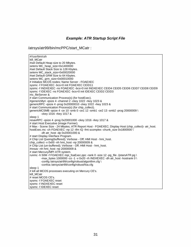
Example: ATR Startup Script File
/atrsys/atr99/bin/mcPPC/start_MCatr :
#!/usr/bin/cshkill_MCatr#set Default Heap size to 20 Mbytes.setenv MC_heap_size=0x1400000#set Default Stack Size to 128 Kbytes.setenv MC_stack_size=0x00020000#set Default GRM Size to 64 Kbytes.setenv MC_grm_size=0x00010000# Initialize MCOS nodes; Name Server - FOAEXECsysmc -f FOAEXEC -bcs=0 init FOAEXEC CEID11sysmc -f INDXEXEC -ns FOAEXEC -bcs=0 init INDXEXEC CEID4 CEID5 CEID6 CEID7 CEID8 CEID9sysmc -f IDEXEC -ns FOAEXEC -bcs=0 init IDEXEC CEID2 CEID3mc_fileServer &# start Communication Process(s) (for hostExec).#genericMyri -qsize 4 -channel 2 -ckey 1022 -rkey 1023 &genericRPC -qsize 4 -prog 0x20000010 -ckey 1022 -rkey 1023 &# start Communication Process(s) (for chip_collect).genericMCSMB -qsize 4 -ce 10 -smb 0 -ce1 12 -smb1 -ce2 13 -smb2 -prog 20000009 \
-ckey 1016 -rkey 1017 &sleep 1resavRPC -qsize 4 -prog 0x20001000 -ckey 1016 -rkey 1017 &# start Host Executive (image Former).# Max - Scene Size - 24 Mbytes; ATR Report Host - FOAEXEC; Display Host (chip_collect)- atr_host.hostExec.mc -ch FOAEXEC -np 12 -tfm IQ -fmt scomplex -chunk_size 0x1800000 \
-dh atr_host -dp 0x20001000 &# start Display Interface Program.# Chip List Queing(buffered); Verbose - Off; HMI Host - hmi_host.chip_collect -v 0x00 -nh hmi_host -np 20000009 &# Chip List (un-buffered); Verbose - Off; HMI Host - hmi_host.#resav -nh hmi_host -np 20000009 &# start Mercury/MPI ATR system.runmc -h 50M -f FOAEXEC mpi_foaExec.ppc -rank 0 -size 12 -pg_file ./jstarsATR.pg \
-max_bytes 1000000 -co -1 -v 0x20 -rh INDXEXEC -dh atr_host -hostrank 0 \-config /atrsys/atr99/config/robust/algorithm.cfg \-confoa /atrsys/atr99/config/robust/foa.cfg
sleep 1# kill all MCOS processes executing on Mercury CE's.kill_MCatr# reset MCOS CE's.sysmc -f FOAEXEC resetsysmc -f INDXEXEC resetsysmc -f IDEXEC reset
32
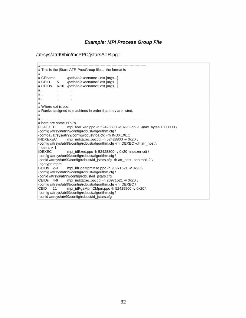
Example: MPI Process Group File
/atrsys/atr99/bin/mcPPC/jstarsATR.pg :
#----------------------------------------------------------------------------------------# This is the jStars ATR ProcGroup file... the format is## CEname /path/to/execname1.ext [args...]# CEID 5 /path/to/execname2.ext [args...]# CEIDs 6-10 /path/to/execname3.ext [args...]# . . .# . . .# . . .## Where ext is ppc.# Ranks assigned to machines in order that they are listed.##----------------------------------------------------------------------------------------# here are some PPC'sFOAEXEC mpi_foaExec.ppc -h 52428800 -v 0x20 -co -1 -max_bytes 1000000 \-config /atrsys/atr99/config/robust/algorithm.cfg \-confoa /atrsys/atr99/config/robust/foa.cfg -rh INDXEXECINDXEXEC mpi_indxExec.ppccdi -h 52428800 -v 0x20 \-config /atrsys/atr99/config/robust/algorithm.cfg -rh IDEXEC -dh atr_host \-hostrank 1IDEXEC mpi_idExec.ppc -h 52428800 -v 0x20 -indexer cdi \-config /atrsys/atr99/config/robust/algorithm.cfg \-conid /atrsys/atr99/config/robust/id_jstars.cfg -rh atr_host -hostrank 2 \-pgatype mpmCEIDs 2-3 mpi_idPgaMpmMse.ppc -h 20971521 -v 0x20 \-config /atrsys/atr99/config/robust/algorithm.cfg \-conid /atrsys/atr99/config/robust/id_jstars.cfgCEIDs 4-9 mpi_indxExec.ppccdi -h 20971521 -v 0x20 \-config /atrsys/atr99/config/robust/algorithm.cfg -rh IDEXEC \CEID 11 mpi_idPgaMpmCMpm.ppc -h 52428800 -v 0x20 \-config /atrsys/atr99/config/robust/algorithm.cfg \-conid /atrsys/atr99/config/robust/id_jstars.cfg
33
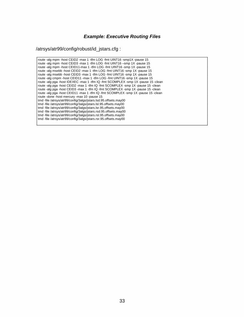
Example: Executive Routing Files
/atrsys/atr99/config/robust/id_jstars.cfg :
route -alg mpm -host CEID2 -max 1 -tfm LOG -fmt UINT16 -smp1X -pause 15route -alg mpm -host CEID3 -max 1 -tfm LOG -fmt UINT16 –smp 1X -pause 15route -alg mpm -host CEID11-max 1 -tfm LOG -fmt UINT16 -smp 1X -pause 15route -alg msebb -host CEID2 -max 1 -tfm LOG -fmt UINT16 -smp 1X -pause 15route -alg msebb -host CEID3 -max 1 -tfm LOG -fmt UINT16 -smp 1X -pause 15route -alg cmpm -host CEID11 -max 1 -tfm LOG -fmt UINT16 -smp 1X -pause 15route -alg pga -host IDEXEC -max 1 -tfm IQ -fmt SCOMPLEX -smp 1X -pause 15 -cleanroute -alg pga -host CEID2 -max 1 -tfm IQ -fmt SCOMPLEX -smp 1X -pause 15 -cleanroute -alg pga -host CEID3 -max 1 -tfm IQ -fmt SCOMPLEX -smp 1X -pause 15 -cleanroute -alg pga -host CEID11 -max 1 -tfm IQ -fmt SCOMPLEX -smp 1X -pause 15 -cleanroute -done -host mercury -max 10 -pause 15tmd -file /atrsys/atr99/config/3algs/jstars.lsd.95.offsets.may00tmd -file /atrsys/atr99/config/3algs/jstars.lsl.95.offsets.may00tmd -file /atrsys/atr99/config/3algs/jstars.lsr.95.offsets.may00tmd -file /atrsys/atr99/config/3algs/jstars.rsd.95.offsets.may00tmd -file /atrsys/atr99/config/3algs/jstars.rsl.95.offsets.may00tmd -file /atrsys/atr99/config/3algs/jstars.rsr.95.offsets.may00

34
Appendix C:Interface Requirements
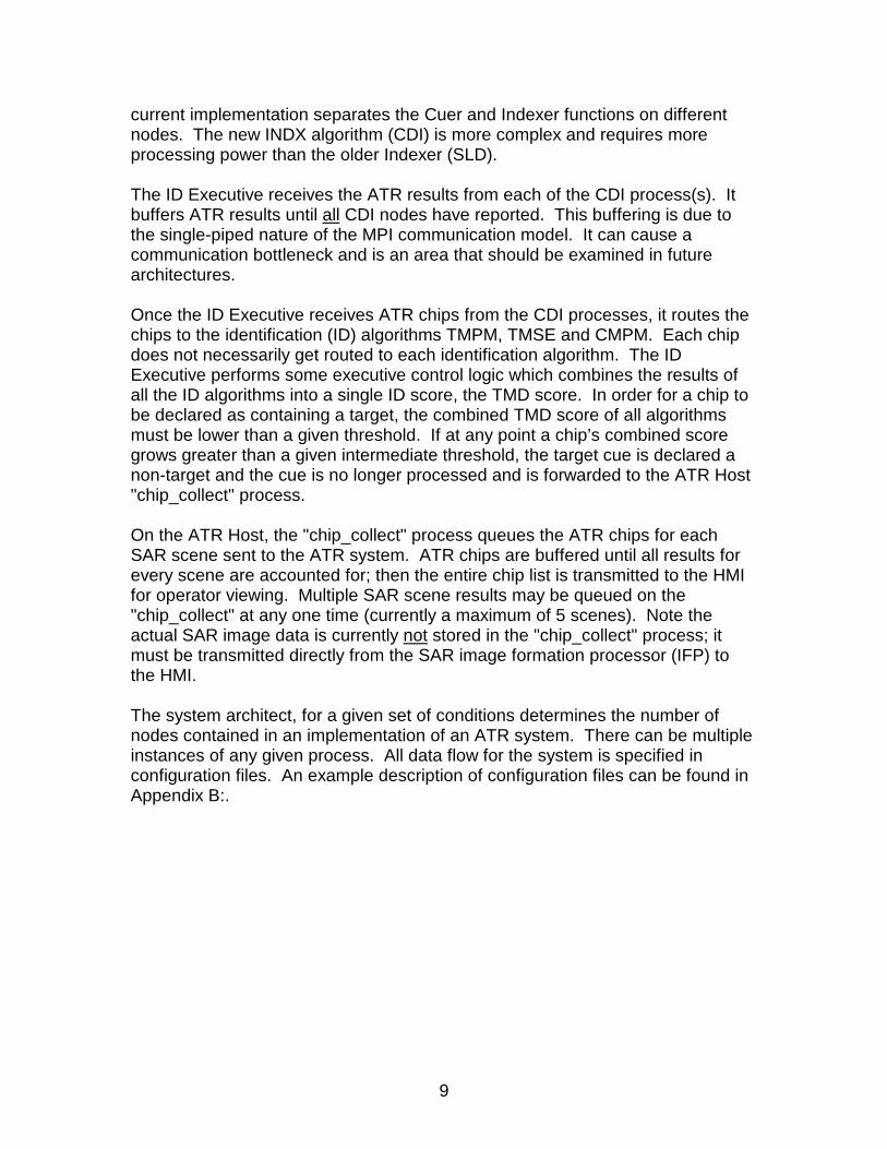
There are two interfaces to the Real-Time ATR System, an input image interfaceand a result interface. Synthetic aperture radar images are sent to the ATRusing the input image interface. The ATR system processes the image andtransmits it's results to a human machine interface (HMI) or another applicationusing the result interface.
Both interfaces use the Sandia ATR Chip API protocol. The API is a way ofmanaging ATR image data, algorithm cues, and algorithm results within real-timeATR processing systems. It also provides APIs for communicating this databetween real-time ATR processing modules. By using a unified API betweensoftware modules, the process of connecting modules and building the top-levelcontrol structure of an ATR system is simplified. For a tutorial on the ATR ChipAPI and examples for sending and receiving ATR Chip data, refer to the ATRChip API User's Manual1,2.
The image and results interfaces can be a Myrinet3 connection or any hardwaretransport that supports RPC/TCP/IP internet protocols, e.g. 10/100 BaseTEthernet or FDDI. The advantage of using Myrinet is that the ATR Chip APIcommunication routines use the Myrinet API as the middle layer protocol. Thisprovides a much higher performance (increased bandwidth with lower latencies)interface for sending and receiving ATR Chip data. The disadvantage of its useis that it requires a node in the system, which can accept a Myrinet host adapterinterface and is supported by Myricom software drivers.
Image FormationProcessor
or simulator
Real-TimeATR System
HumanMachineInterface• ATR Chip API Protocol
• RPC or Myrinet API• Myrinet or any supported TCP/IP capable interconnect.

35
genericMyri
"genericMyri" is a server process used on the ATR Host to receive image dataand algorithm results from external sources. A single instance runs on everynode in the system with Myrinet communications. The "genericMyri" processshould run at a high priority. This allows the ATR Host to immediately receiveincoming data from a client (IFP), thus preventing the client from blocking andhence slowing other client tasks*. In addition, communication processing canoccur at the same time as computation processing. As messages are receivedfrom clients, they are put into a receiving buffer for a worker task, i.e. the ImageFormer process. When a worker task is ready for a new ATR Chip message, itretrieves it from the receive buffer. After processing the message, the updatedATR Chip information is sent to the next process in the data flow.
There can only be one "genericMyri" task per node. If there are multiple workertasks per node, the single "genericMyri" process receives all data and eachworker process would have its own Input Queue. The client is able to indicatewhich buffer to put the data in by specifying a service number. At startup,"genericMyri" is configured with a given number of receive buffers and a servicenumber for each buffer.
There is however a limit to the number of messages the genericMyri task will accept. If the limit isreached, it will no longer accept new messages. In this case the client process will be blocked.This prevents the Host's memory from being used up if it is sent too many messages at one time.
genericMyri Process Architecture
genericMyriProcess
WorkerProcess
Input Queue
ClientProcess
To nextnode
Myrinet
Node A
SMB orMPI
Node B
36
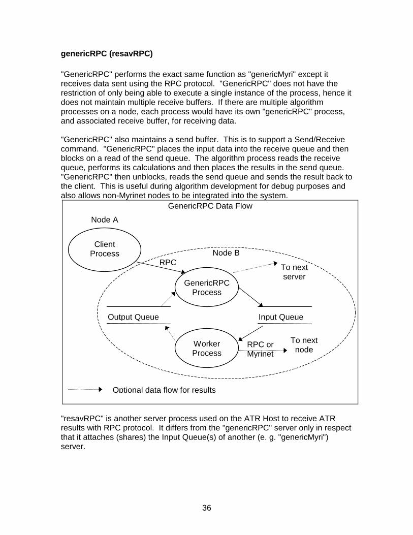
genericRPC (resavRPC)
"GenericRPC" performs the exact same function as "genericMyri" except itreceives data sent using the RPC protocol. "GenericRPC" does not have therestriction of only being able to execute a single instance of the process, hence itdoes not maintain multiple receive buffers. If there are multiple algorithmprocesses on a node, each process would have its own "genericRPC" process,and associated receive buffer, for receiving data.
"GenericRPC" also maintains a send buffer. This is to support a Send/Receivecommand. "GenericRPC" places the input data into the receive queue and thenblocks on a read of the send queue. The algorithm process reads the receivequeue, performs its calculations and then places the results in the send queue."GenericRPC" then unblocks, reads the send queue and sends the result back tothe client. This is useful during algorithm development for debug purposes andalso allows non-Myrinet nodes to be integrated into the system.
"resavRPC" is another server process used on the ATR Host to receive ATRresults with RPC protocol. It differs from the "genericRPC" server only in respectthat it attaches (shares) the Input Queue(s) of another (e. g. "genericMyri")server.
GenericRPC Data Flow
GenericRPCProcess
WorkerProcess
Input Queue
ClientProcess
To nextnode
Output Queue
To nextserver
Optional data flow for results
Node A
Node BRPC
RPC orMyrinet
37
Distribution:
1 MS 0844 Drayton Boozer, 1535220 MS 0844 Wallace Bow, 153521 MS 0844 Brian Bray, 153521 MS 1110 Douglas Doerfler, 92232 MS 0980 Richard H. Meyer, 57211 MS 1110 Neil Pundit, 92231 MS 9018 Central Technical Files, 8945-12 MS 0899 Technical Library, 96161 MS 0612 Review & Approval Desk, 9612
for DOE/OSTI


![Engineering Geology...AAU Office of the Registrar De 't: Civil En ineerin Program: Section: 4 course Code; CENG ID.NO ATR12152]05 ATR/5749/05 ATR/4526/05 ATR/7587/06 ATR/2774/05 ATR/5278/05](https://img.pdfslide.us/doc/110x75/60f5164ac9e9827e9d545c73/engineering-geology-aau-office-of-the-registrar-de-t-civil-en-ineerin-program.jpg)


![What is [Open] MPI?open]-mpi-1up.pdfMay 2008 Screencast: What is [Open] MPI? 3 MPI Forum • Published MPI-1 spec in 1994 • Published MPI-2 spec in 1996 Additions to MPI-1 • Recently](https://img.pdfslide.us/doc/110x75/6143c7b66b2ee0265c024306/what-is-open-mpi-open-mpi-1uppdf-may-2008-screencast-what-is-open-mpi-3.jpg)


![What is [Open] MPI?open]-mpi-2up.pdf2 May 2008 Screencast: What is [Open] MPI? 3 MPI Forum • Published MPI-1 spec in 1994 • Published MPI-2 spec in 1996 Additions to MPI-1 •](https://img.pdfslide.us/doc/110x75/6143c7b46b2ee0265c024305/what-is-open-mpi-open-mpi-2uppdf-2-may-2008-screencast-what-is-open-mpi.jpg)