Embed Size (px)
Citation preview
29th Annual Precise Time and Time Interval (PTTI) Meeting
/-
ATOMIC FREQUENCY STANDARDS FOR THE GPS IIF SATELLITES
Willem Emmer, Boeing
Eric Watts, Boeing
Abstract
The GPS IIF block of satellites will camy Cs beam and Rb vapor cell atomic frequency standads. This paper presents a description of the two frequency standards and reviews their expected performance. The pedomame of the two technologies is also assessed within the context of the orbital environment. User range error, a measure of accuracy, is calculated based on projected performance of the IIF fiequency stundurdk Potential system performance improvements, possible with two future clock technologies, are also considered.
INTRODUCTION
Atomic frequency standards and the ultra-stable signal they provide enable the present GPS constellation and future GPS satellites to broadcast highly accurate navigation signals. The GPS IIF satellites will take advantage of recent advancements in frequency standard technology to improve upon the performance of the GPS Constellation. The current configuration of the GPS IIF satellites provides two cesium frequency standards (CFS) and two rubidium frequency standards (RFS) in response to the Government’s system requirement for two frequency standard technologies to be provided on each satellite.
The GPS IIF Navigation Payload utilizes the same architecture as the successful GPS Block MIA Space vehicles. The Navigation Payload is comprised of four atomic frequency standards (AFSs), a frequency synthesizer & distribution unit (FSDU), the cross-link transponder & data unit (CTDU), and the navigation data unit (NDU). Each frequency standard outputs an ultra-stable 10.23MHz signal to the FSDU. The FSDU modifies that signal as required to support selective availability and distributes the signal to the NDU and other signal users. The NDU uses the 10.23MHz signal to generate the pseudo-random noise ranging codes (C/A & P(Y)), build the navigation message, and combine these two signals for modulation on the L-band carriers.
GPS IIF ATOMIC FREQUENCY STANDARDS
The cesiumbeam frequency standards will be produced by Frequency and Time Systems (F&TS), a division of Datum Inc. The rubidium gas cell standards will be produced by EG&G’s Electro-optics Division.
201
CESIUM ATOMIC FREQUENCY STANDARD
Frequency and Time Systems, which designed and built the cesium frequency standards for the GPS I and II/IIA satellites, was selected to develop and produce the cesium standards for the GPS-ITF program. F&TS’s new cesium frequency standard design, designated the Model FTS 4410, will space-qualify microprocessor control technology for the frequency standard. The new design follows from F&TS developmental work sponsored by the Naval Research Laboratow (NlU).
The heart of the design is the cesium beam tube (CBT) which provides a suitable environment in which a beam of cesium atoms may be interrogated by a microwave field at 9.192 ... GHz. The Model FE3 7610 CBT used in the 4410 has its design heritage in the Cs beam tubes (CBTs) used in the GPS I and WE4 clocks. For use in GPS IIF, the 7610 was enhanced to provide longer life, increased accuracy and frequency stability. Of particular concern in a CBT is the trade-off between short-term stability and lifetime, An increase in cesium beam intensity results in an improvement in short-term frequency stability at the expense of CBT lifetime. The 7610 is designed to meet the frequency stability requirements of GPS IEJ while supporting a l0year operating life requirement. The CBT design must also withstand the mechanical rigors of satellite launch. Comprehensive vibration testing (to the GPS IIF qualification levels) of the FI‘S 7610 during the development phase has demonstrated that the design can survive and perform after exposure to the launch environment.
The enabling technology for the 4410 operation and performance is an embedded microprocessor. The microprocessor and its software algorithms perform several important tasks which include: lock acquisition at start-up; operation of the primary frequencyhck loop; operation of several “background” servos which stabilize the atomic interrogation process; and comprehensive monitoring of system operation to provide a robust indicator of clock state-of-health. Multiple software servos operate in the 4410 to continuously optimize its performance. The 4410 employs a servo architecture which “time shares” the atomic interrogation process among several tasks. The primary servo serves to frequencflock the oven controlled quartz oscillator (OCXO) to the atomic resonance, thereby providing a clock output signal with the frequency accuracy and stability of the cesium atomic beam. Periodically, a “stolen cycle” is used to acquire information for one of several background servos; these servos control signal gains, interrogating microwave power, as well as the magnetic field within the cesium beam tube, to negate the effects of external magnetic fields. The time-sharing technique has the advantage that the primary servo is uncontaminated by the activity of the background servos. The multiple servos do not occupy the full processing capability of the microprocessor. The otherwise spare processor time is used to monitor numerous internal clock parameters to provide a robust and comprehensive evaluation of clock state-of- health. Twenty-eight internal parameters are monitored and reported over a satellite telemetry data channel,
The synthesizer is another important element in the atomic frequency standard. The synthesizer translates the clock output frequency (10.23 MHz in the case of GPS IF clocks) to the atomic resonance frequency (9 19263 1770 Hz for cesium). There are several requirements for this synthesizer: the signal at the atomic resonance frequency must be free of significant spurious responses which may cause “frequency pulling”, a shift of the atomic resonance. The synthesizer must be able to generate interrogating signals at various frequencies within the cesium atomic resonance structure The output power of the synthesizer must be controllable. Additionally, operation of the primary frequency lock loop servo requires a square wave frequency modulation of the interrogating signal. The OCXO at 10.23 MHz is the starting point. Frequency multipliers translate the frequency to the GHz realm. A surface acoustic wave (SAW) oscillator running at 9.192 GHz is controlled in an offset phasdock loop to provide a “clean”, spuriouefree microwave signal for interrogation of the cesium atoms. The reference for the offset PLL is generated in a direct digital synthesizer (DDS) under control of the microprocessor. Microprocessor commands sent to
P
-.
202
the DDS are translated to the SAW output frequency, thereby providing an ability to interrogate features of the atomic resonance.
The interrogating signal microwave power may change with time as a result of temperature, aging, or radiation effects upon the electronics. These changes in microwave power levels can, in turn, cause frequency instabilities in the clock. The microwave power servo modulates the microwave power, providing information which is used to optimize the microwave power level without contamination of the primary frequency lock loop performance.
The Model 9400-520 OCXO used in the 4410 CFS was developed specifically for use in space and contains a third overtone SC-cut resonator at 5.115 MHz.. A doubler within the oscillator provides an output at 10.23 MHz. It has been used in numerous satellite applications.
RUBIDIUM ATOMIC FREQUENCY STANDARD
The Rubidium Frequency Standard (WS) design evolved directly from a previously spacequalified design and employs classical rubidium gas cell principles. A voltagecontrolled crystal oscillator at 10.23 MHz, synthesized from the Rb hyperfine resonant frequency, provides the output via an amplifier and crystal filter. Another crystal oscillator, resonant at approximately 13.4 MHz, excites the Rb physics package via a phase modulator and frequency multiplier chain. This produces a discriminator signal which is processed by a servo amplifier to lock that crystal to the Rb atomic resonance.
The classical rubidium gas cell principles used in the design of the frequency standard give the highest available performance consistent with program constraints. The discrete isotropic filter cell gives zero light shift over a range of light intensity and high signakwoise ( S M ) ratio. This permits operation at a relatively low light level, thus reducing temperature and RF power dependencies.
The RF multiplier chain consists of a 13.4MHz voltagPcontroIled crystal oscillator (VCXO), a phase modulator, a diode tripler, a push-push doubler, and a x85 step recovery diode (SRD) multiplier. The low noise of the Rb reference permits a tight lock loop that allows the use of the low-complexity, non-ovenized crystal oscillator, An automatic level control loop is used to maintain constant drive to the SRD multiplier and a high-Q helical resonator RF bandpass filter is used ahead of the SRD multiplier. This approach provides high stability and spectral purity. A clean modulation waveform is generated by passive integration of a precision squarewave, and highly linear phase modulation is obtained by applying small excursions to a varactor diode,
The RFS synthesizer consists of a phaselock loop employing two divider chains and a 10.23MHz VCXO. The 13.4MHz signal is divided by 3051 and the 10.23MHz signal is divided by 2329. These divider circuits provide frequencies of 4.39kHz to a phase detector. The phase detector in turn drives loop compensation amplifiers which steer the varactor tuning of the 10.23MHz VCXO.
The output amplifier provides a +18dBm low-distortion output and maintains a phase-continuous output under transient radiation. This “flywheel” effect is provided by a LC output tank and crystal bandpass filter.
The ITF RFS includes a built-in baseplate temperature controller. This controller maintains the baseplate of the RFS electronics at +45OC 5 0.loC,thus essentially eliminating the effects of space vehicle temperature variations.
203
NAVIGATION TIMING ERROR ANALYSIS
7
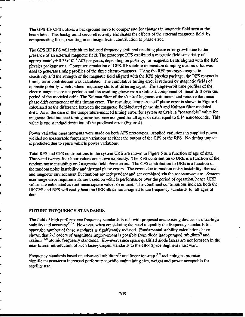
Timing of the navigation message is critical to GPS system performance where timing and positional accuracy are intimately tied via the speed of light. A onenanosecond timing error yields a 0 . h e t e r range error. The frequency standards are allocated a timing requirement in term of User Range Error (URE) measured in meters. The bar chart of Figure 1 illustrates the GPS-IIF URE allocations including that of the frequency standards at an “age of data” (AOD) equal to 24 hours. Behind the control segment the frequency standards’ performance is the major driver in the positional accuracy of the GPS Constellation. Age of data refers to the elapsed time since synchronization of a given space vehicle to GPS-time as defined-by the Control SegmentSynchronization occurs at least once every 2.4 houqbut as often as every 15 minutes,as a means to limt a space vehicle‘s phase offset from system time an4hencGits range error. Error growth over the specified 24-hour period is of primary concern from the frequency standard design standpoincsince the frequency standard must perform over this time interval with prescribed stability.
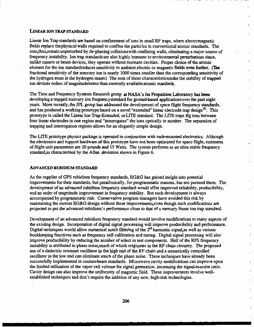
The frequency stability of the GPS-IF standards, as characterized by Allan deviation, is shown in Figure 2 along with measurements of the IlF CFS & RFS prototype stabilities+ This random noise instability results in the largest contribution to URE. The required on-orbit performance of the GPS El? frequency standards demands that both units have minimal environmental sensitivities. Thermal and magnetic environment fluctuations degrade the AFS’s performance. An analysis was performed to estimate these effects and the results are presented below.
Random noise processes in frequency standards contribute to timing errors, and so called “optimum predictor” methods for estimating these contributions have been developed‘”’. The method employed in this analysis accounts for the various noise processes that are used to model observed in~tabilities‘~~ lo).
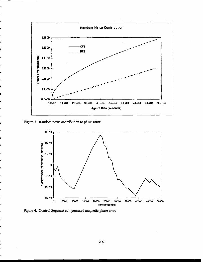
Based on the measured prototype performance, noise processes of the GPS frequency standards were estimated and used to calculate timing error growth over age of data, as shown in Figure 3. The analysis assumes perfect control segment modeling; the actual timing error, at zero age of data, will be small, but non zero.
The space vehicle will see a periodic thermal environment resulting in k 3 “C changes at the frequency standards’ baseplates. Since the FWS utilizes an integral baseplate temperature control unit to actively eliminate thermal variations, these fluctuations are of no consequence. The cesium standard, however, is affected. The temperature variation induces a sinusoidal frequency shift that is directly proportional to the measured thermal sensitivity of -3~10-l~ Af/fPC. Time integration of the frequency offset yields the timing error which is also sinusoidal with a pe&to+mk magnitude of 1.24 nanoseconds. This timing error is deterministic, but since control segment uplinks are not correlated with the thermal environment, the error cannot be fully removed. The Kalman filter of theControl Segmcntwill partially compensate for this error,resulting in a cyclic temperatuminduced timing error of zero mean and of the same magnitude of 1.24 nanoseconds. For system analysis for all ages of data, a value for the thermal timing error of one standard deviation is used, equal to 0.88 nanoseconds.
The frequency standards are also subject to external magnetic fields which will induce frequency shifts. The magnetic field of most concern is generated by three “torque-rod” electro-magnets in the Attitude, Determination & Control System (ADCS). The magnetic field at the location of each frequency standard depends upon the distance to each electro-magnet and its polarity. Preliminary calculations show that the cesium frequency standards will see a field as large as 1.64 gauss and the RFS a 0.88-gauss field. The electromagnet duty cycle and polarity varies, with the minimum on time for each magnet being 100 seconds.
4
1
1
204
b
c
The GPS-IIF CFS utilizes a background servo to compensate for changes in magnetic field seen at the beam tube. This background servo effectively eliminates the effects of the external magnetic field by compensating for it, resulting in an insignificant contribution to phase error.
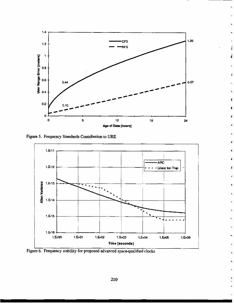
The GPS IIF RFS will exhibit an induced frequency shift and resulting phase error growth due to the presence of an external magnetic field. The prototype RFS exhibited a magnetic field sensitivity of approximately& 0.33~10' '~ Af/f per gauss, depending on polarity, for magnetic fields aligned with the RFS physics package axis, Computer simulation of GPS-IIF satellite momentum dumping over an orbit was used to generate timing profiles of the three electro-magnets. Using the RFS prototype magnetic sensitivity and the strength of the magnetic field aligned with the RFS physics package, the RFS magnetic timing error contribution was calculated. The cumulative timing error is reduced by magnetic fields of opposite polarity which induce frequency shifts of differing signs. The single-orbit time profiles of the electro-magnets are not periodic and the resulting phase error exhibits a component of linear drift over the period of the modeled orbit. The Kalman filter of the Control Segment will model and remove the linear phase drift component of this timing error. The resulting "compensated" phase error is shown in Figure 4, calculated as the difference between the magnetic field-induced phase shift and Kalman filter-modeled drift. As in the case of the temperatureinduced timing error, for system analysis, a 'Yeasonable" value for magnetic fielchduced timing error has been assigned for all ages of data, equal to 0.14 nanoseconds. This value is one standard deviation of the predicted error (Figure 4).
Power variation measurements were made on both AFS prototypes. Applied variations in supplied power yielded no measurable frequency variations at either the output of the CFS or the RFS. No timing impact is predicted due to space vehicle power variations.
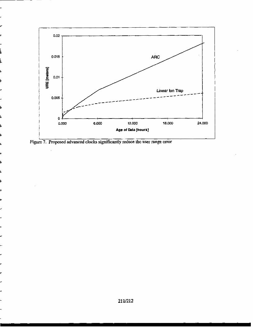
Total RFS and CFS contributions to the system URE are shown in Figure 5 as a function of age of data. Thresand twenty-four hour values are shown explicitly. The RFS contribution to URE is a function of the random noise instability and magnetic field phase errors. The CFS contribution to URE is a function of the random noise instability and thermal phase errors. The errors due to random noise instability, thermal and magnetic environment fluctuations are independent and are combined via the root-sumquare. System user range error requirements are based on vehicle performance over the period of operation, hence URE values are calculated as root-mean-square values over time. The combined contributions indicate both the I F CFS and RFS will easily beat the URE allocation assigned to the frequency standards for all ages of data.
FUTURE FREQUENCY STANDARDS
The field of high performance frequency standards is rich with proposed and existing devices of ultra-high stability and accuracy'"). However, when considering the need to qualify the frequency standards for spacqthe number of these standards is significantly reduced. Fundamental. stability calculations have shown that 2-3 orders of magnitude improvement is possible from diode laser-pumped rubidiud3' and cesium (4*5) atomic frequency standards. However, since spacequalified diode lasers are not foreseen in the near future, introduction of such laserpumped standards to the GPS Space Segment must wait.
Frequency standards based on advanced rubidium'6) and linear ion-trap"**) technologies promise significant n-erm increased performanceawhile maintaining size, weight and power acceptable for satellite use.
205
LINEAR ION TRAP STANDARD
Linear Ion Trap standards are based on confinement of ions in small FtF traps, where electromagnetic fields replace thephysical walls required to confine the particles in conventional atomic standards. The ions,thuqremain unpermrbed by de-phasing collisionswith confining walls, eliminating a major source of frequency instability. Ion trap standards are also highly immune to environmental perturbations since, unlike masers or beam devices, they operate without resonant cavities. Roper choice of the atomic element for the ion standardreduces sensitivity to ambient electric or magnetic fields even further. (The fractional sensitivity of the mercury ion is nearly loo0 times smaller than the corresponding sensitivity of the hydrogen atom in the hydrogen maser) The sum of these characteristicsmake the stability of trapped ion devices orders of magnitudebetter than currently availableatomic standards.
The Time and Frequency Systems Research group at NASA’s Jet propulsion Laboratory has becn developing a trapped mercury ion frequencystandard for ground-based applicationsover the past eight years. More recently, the JPL group has addressed the development of space flight frequency standards, and has produced a working prototype based on a novel “extended” linear electrode trap design“’. This prototype is called the Linear Ion Trap-Extended, or LITE standard. The LITE traps Hg ions between four linear electrodes in one region and “interrogates” the ions optically in another. The separation of trapping and interrogation regions allows for an elegantly simple design.
The LlTE prototype physics package is operated in conjunction with rack+nounted electronics. Although the electronics and support hardware of this prototype have not been optimized for space flight, estimates of flight unit parameters are 20 pounds and 15 Watts. The system performs as an ultra-stable frequency standard,as characterized by the Allan deviation shown in Figure 6.
ADVANCED RUBIDIUM STANDARD
As the supplier of GPS rubidium frequency standards, EG&G has gained insight into potential improvements for their standards, but paradoxically, for programmatic reasons, has not pursued them. The development of an advanced rubidium frequency standard would offer improved reliability, producibility , and an order of magnitude improvement in frequency stability. But such development is always accompanied by programmatic risk. Conservative program managers have avoided this risk by maintaining the current EG&G design without these improvements,even though such modifications are projected to put the advanced rubidium’s performance close to that of a mercury linear ion trap standard.
Development of an advanced rubidium frequency standard would involve modifications to many aspects of the existing design. Incorporation of digital signal processing will improve producibility and performance. Digital techniques would allow numerical notch filtering of the Zd harmonic signal,as well as various bookkeeping functions such as frequency self-calibration and tuning. Digital signal processing will also improve producibility by reducing the number of select in test components. Half of the RFS frequency instability is attributed to phase noisGmuch of which originates in the RF chain circuitry. The proposed use of a dielectric resonant oscillator in the high end of the FCF chain and a numerically controlled oscillator in the low end can eliminate much of the phase noise. These techniques have already been successfully implemented in cesiu&am standards. Microwave cavity modifications can improve upon the limited utilization of the vapor cell volume for signal generation, increasing the signakcmoise ratio. Cavity design can also improve the uniformity of magnetic field. These improvements involve well- established techniques and don’t require the addition of any new, high-risk technologies.
1
206
CONCLUSION
I i
b
Future implementation of ultra-precision frequency standards can improve the accuracy of the GPS system by nearly eliminating the AFS noise contribution to URE for all ages of data. However, the GPS “System” performance in the ID? timeframe will be principally determined by short-term AFS performance with age of data of 3 hours or less because of the unique GPS-IIF “crosslink update mode” and operational approaches. Figure 7 shows the prajected random noise contribution to user range error for the advanced rubidium and linear ion-trapbased standards. The random noise error can be reduced to a few centimeters at 24 hours,as compared to the -1 meter-noise contribution of current standards.
REFERENCES , .-
i
1. L. Maleki, Frequency Standards from Government Over the Next 25 Years, Proceedings of the 25th Meeting PTTI, 1994.
2. N. Ramsey, The Past, Present, and Future of Atomic Time and Frequency, Proceedings of the IEEE, Vol. 79, No. 7,1991.
3. J. Compararo, R. Frueholtz, Fundamental Stability limits for the Diode-Laser Pumped Rubidium Atomic Frequency Standard, J. Applied Physics, Vol. 59, May 15, 1986.
4. R. Drullinger, Frequency Standards Based on Optically Pumped Cesium, Proceedings of the IEEE, Vol. 74, No. 1, Jan. 1986.
5. R. Drullinger et. al., The NIST Optically Pumped Cesium Frequency Standard, lEEE Transactions on Instrumentation and Measurement, Vol. 40, No. 2, April 1991.
6. William Riley, EG&G Electro-Optics Division, Private Communication, 1997. 7. J. Restage et. al., Improved Linear Ion Trap Physics Package, Proceedings of the IEEE International
Frequency Control Symposium, 1993. 8. J. Prestage and L. Maleki, Space Flyable Hg Frequency Standards, Proceedings of the IEEE
International Frequency Control Symposium, 1994. 9. D. Allan and H. Hellwig, Time Deviation and Time Prediction Error for Clock Specification,
Characterization and Application, Roc. Of Position, Location, and Navigation Symp., San Diego CA, N0~.7-9,1978, ~ ~ 2 9 - 3 6 .
10. D. Allan, Addendum Paper to: Time Deviation and Time Prediction Error for Clock Specification,
11. D. Allan, Time and Frequency (Time-Domain) Characterization, Estimation, and Prediction of Characterization and Application (see ref. 9), March, 1981.
Precision Cocks and Oscillators, IEEE Trans. on Ultrasonics, Ferroelectrics, and Frequency Control, Vol. UFFC-34, NO. 6, Nov., 1986.
12. R. Ghassemi and S. Fisher, Performance Projections of GPS-IXF, Proceedings of the Institute of Navigation, 1997.
V
4, i
Figure 1. Significant allocated user range error contributions for the GPS-IIF satellites. I
1.E-I1
1.E12
1.513
1.E14 ! 1 1 .boo 1 .Wl 1 .Go2 1 .E+m 1 .w 1 .E+o5 1 . W S
Tau [seconds]
Figure 2. Preliminary AFS prototype stability data
208
1
r
5.E-09
- p 4.EW
Q E 0
- 3.EW
W 0
c P
2.E09
o.E+oo
Random Noise Contribution
0 . W l.L.04 2.- 3.l3-04 4 . W 5.- 6 . W 7 . W 8.- 9 . W
Age of Data [seconds]
Figure 3. Random noise contribution to phase error
3E-10 ~
0 5000 loo00 15000 2oooO BOO0 30000 SO00 40000 45000 5OOOO Time [seconds]
Figure 4. Control Segment compensated magnetic phase error
209
I
1.4
1.2
0.2
0
1.26
0.57
1
0 6 12 18 24 Age of Data [hours]
Figure 5. Frequency Standards Contribution to URE
1.Sll
1.E12
1.E13
1.514
1.E15
1.616 1 .Em0 1 .Ml 1 . w 2 1 .Em 1 .m 1 .E+O5 1 .E+m
Time [seconds]
U
Y
1
1
210 U
i
L
. ~~ ~
0.02
0.015
T g 0.01 Y
ru OE 3
0.005
O-OOO 6.000 12.000 18.000 24.000
Age of ma [hours]
Figure 7. Proposed advanced clocks significantly reduce the user range error
c
21 11212


![Web view15.10.2015 · -ValueMergeType 'Update' ` ... -Expression 'IIF(IsPresent([cloudSourceAnchor]), IIF(Word](https://img.pdfslide.us/doc/110x75/5a9e34d57f8b9a0d7f8ba421/web-view15102015-valuemergetype-update-expression-iifispresentcloudsourceanchor.jpg)