Embed Size (px)
Citation preview
42nd
Annual Precise Time and Time Interval (PTTI) Meeting
181
GPS BLOCK IIF ATOMIC FREQUENCY
STANDARD ANALYSIS
Francine Vannicola, Ronald Beard, Joseph White, Kenneth Senior
U.S. Naval Research Laboratory
4555 Overlook Avenue, SW, Washington, DC 20375, USA
Marie Largay
Global Defense Technology & Systems, Inc.
James Buisson
Antoine Enterprises, Inc.
Abstract
The first Global Positioning System (GPS) Block IIF space vehicle (SV) was launched on 28
May 2010 with one Digital Cesium Beam Frequency Standard (DCBFS) and two Rubidium
Frequency Standards (RFS) onboard. The DCBFS was manufactured by Symmetricom and the
RFS was manufactured by PerkinElmer Optoelectronics. This paper will present a
performance analysis of the early test operation of the DCBFS and the initial operation of the
RFS. The early orbit data of these two GPS Block IIF space clocks will be compared to the Life
Test data from Block IIF flight-qualified DCBFS and RFS units evaluated at the Naval
Research Laboratory (NRL) prior to space flight. The DCBFS Life Test was conducted with
two flight units between August 2004 and October 2006, and the RFS Life Test has been
ongoing since August 2008.
INTRODUCTION
The NRL is conducting the third in a series of GPS atomic frequency standard life tests in the NRL
Precision Clock Evaluation Facility (PCEF). The PCEF is one of the major facilities within the Naval
Center for Space Technology (NCST). An overview is provided in the NRL 2008 Major Facilities Book
and will be discussed in this paper. The PCEF was originally developed to evaluate high precision atomic
clocks for the GPS concept program (Block I) spacecraft and ground applications. The facility was
expanded for dedicated space clock evaluation conducted for operational system development and
deployment. The progress of space atomic clocks are evaluated, qualified, and acceptance tested for
space flight using the assets of this facility. Testing performed includes long- and short-term performance
evaluation, and environmental testing (including shock and vibration). Investigations of on-orbit
anomalies are performed within the PCEF in an attempt to duplicate and understand similar effects in
space-qualified hardware under controlled conditions. The ability to evaluate and test highly precise
42nd
Annual Precise Time and Time Interval (PTTI) Meeting
182
atomic clocks, especially in a space environment, requires unique facilities, precise time and frequency
references, and precise instrumentation not available elsewhere.
Since the beginning of the GPS program, NRL has been analyzing the on-orbit performance of the GPS
satellite clocks to assess the results of space clocks. During the Block II deployment, NRL began
supplying analysis material to the GPS Operational Control Segment and continues to provide
comprehensive analyses of the GPS atomic frequency standards under the sponsorship of the 2nd Space
Operations Squadron at the Master Control Station (MCS) at Schriever AFB, Colorado.
NRL LIFE TESTS
The first life test conducted at NRL was on the GPS Block IIR Rubidium Atomic Frequency Standard
(RAFS), which began in 1997 and lasted more than 7 years [1-3]. Each Block IIR satellite contains three
RAFS units, built by PerkinElmer Optoelectronics. That life test began about 1 year before any of the
RAFS were used in orbit. Launches of the Block IIR satellites began in 1997 and the last launch occurred
in August 2009.
For the Block IIF program, each satellite will contain one DCBFS and two RFS units. The Block IIF life
test is being conducted in conjunction with the GPS Directorate; the GPS Block IIF Prime Contractor,
Boeing; and the atomic frequency standard manufacturers. On a monthly basis, performance reports are
generated for each atomic frequency standard reviewing the current month and the overall test period.
The reports are made available on a secure NRL Web site for the test participants. The Block IIF life test
is scheduled to run for a minimum of 3 years [4,5].
The second life test of two Block IIF DCBFS units began in August 2004 and has been on hold since
October 2006 due to parts availability problems. One of the DCBFS units was returned to NRL in late
November 2010 and preparations to resume the DCBFS life test are underway. The third life test
involves two production Block IIF RFS units and has run continuously since 22 August 2008.
PRECISE CLOCK EVALUATION FACILITY (PCEF)
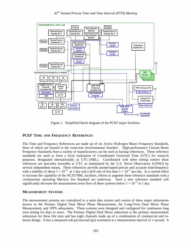
All life tests are being conducted in the NRL PCEF [6]. A block diagram of the facility is shown in
Figure 1. It consists of the following major elements: PCEF Time and Frequency References, Precision
Clock Signal Measurement Systems, Environmental Testing Laboratory, PCEF Data Systems and Server,
and GPS Receiver Laboratory. A large environmental chamber contains the NRL reference hydrogen
masers, the primary digital dual mixer system, and an International Global Navigation Satellite System
(GNSS) Service (IGS) GPS receiver system, that maintains this equipment in a controlled environment to
minimize possible thermal and humidity effects being reflected in their operation and, correspondingly, in
test data. All major components of the PCEF are powered by a 35 KW Uninterruptable Power System for
continuous operation.
42nd
Annual Precise Time and Time Interval (PTTI) Meeting
183
Figure 1. Simplified block diagram of the PCEF major facilities.
PCEF TIME AND FREQUENCY REFERENCES
The Time and Frequency References are made up of six Active Hydrogen Maser Frequency Standards,
three of which are housed in the room-size environmental chamber. High-performance Cesium Beam
Frequency Standards from a variety of manufacturers can be used as backup references. These reference
standards are used to form a local realization of Coordinated Universal Time (UTC) for research
purposes, designated internationally as UTC (NRL). Coordinated with other timing centers these
references are precisely traceable to UTC as maintained by the U.S. Naval Observatory (USNO) by
several independent means. These references provide uninterrupted precise and accurate time/frequency
with a stability of about 1 × 10-15
at 1 day and a drift rate of less than 1 × 10-17
per day. In a current effort
to increase the capability of the NCST/NRL facilities, efforts to augment these reference standards with a
continuously operating Mercury Ion Standard are underway. Such a new reference standard will
significantly decrease the measurement noise floor of these systems below 1 × 10-15
at 1 day.
MEASUREMENT SYSTEMS
The measurement systems are centralized to a main data system and consist of three major subsystems
known as the Primary Digital Dual Mixer Phase Measurement, the Long-Term Dual Mixer Phase
Measurement, and 1PPS subsystems. These systems were designed and configured for continuous long
term testing for days to years. The Primary Digital Dual Mixer subsystem is the primary measurement
subsystem for these life tests and has eight channels made up of a combination of commercial and in-
house design. It has a measured sub-picosecond (ps) resolution at a measurement interval of 1 second. It
42nd
Annual Precise Time and Time Interval (PTTI) Meeting
184
is also housed in the reference environmental chamber in order to minimize any environmental effects on
the measurement electronics. The Long-Term Dual Mixer subsystem is an NRL-built phase measurement
system with a measured 2 ps measurement resolution. It is capable of simultaneous measurements of 48
different channels at a minimum interval of 20 seconds for indefinite test duration, and serves as backup
to the primary system.
ENVIRONMENTAL TESTING LABORATORY
This laboratory has six thermal vacuum chambers especially developed for flight-size GPS atomic clocks
that can be operated continuously for prolonged periods. They are used for simulation of a space-like
environment (< 1 × 10⁻⁵
torr) with temperature control of the baseplate interface to better than 0.1o C. A
large thermal vacuum chamber for larger clocks with a 1 meter by 0.5-meter-diameter chamber is also
used to test larger equipment and is a modified version of a commercial chamber. Another specialized
chamber is currently being evaluated and modified for use in the facility. All vacuum chambers use ultra-
clean turbo-pumps and/or cryo-pumps. Oil diffusion pumps are not employed in any of these chambers.
These chambers are designed to maintain vacuum for up to 1 hour after loss of primary power as a
safeguard for long-term testing integrity. A large environmental chamber is also used for testing at
atmospheric pressure requiring humidity control to 0.5% and temperature sensitivity testing of units with
a resolution of 0.1o C.
LIFE TEST OBJECTIVES
The primary objectives of the life test program is the verification for each type of Block IIF atomic
frequency standard design performance, reliability, and the identification of any potential risks which
might be associated with these atomic frequency standards for satellite applications. A secondary
objective will be to perform long-term characterization and evaluation of the atomic frequency standard
performance parameters under the same space-like conditions that the unit’s on-orbit would experience,
providing the ability to enhance the confidence in the atomic frequency standard design for future GPS
development. DCBFS and RFS on-orbit data will be combined with the ground test data to support
reliability and life analysis as the Block IIF satellites are launched.
LIFE TEST CONFIGURATION
The life test principal objectives are to be accomplished by evaluating each Block IIF flight unit under
continuous operation in a simulated space-like environment replicating their operation in the GPS
spacecraft as closely as possible. Separate thermal vacuum chambers whose mounting baseplates are
independently temperature controlled are being used to house each of the units. To ensure the mounting
conditions are as close as possible to that in the spacecraft, Boeing personnel installed each test unit into
its thermal chamber at NRL using the same procedures and materials used for satellite installation. Two
different test configurations were used for the RFS and DCBFS life tests. A brief description for both test
configurations will be described.
RFS LIFE TEST
The two RFS flight production units chosen, serial numbers 5 and 25, were put into life test in August
2008. Designated RFS05 and RFS25, the units were not modified in any way for the life test program.
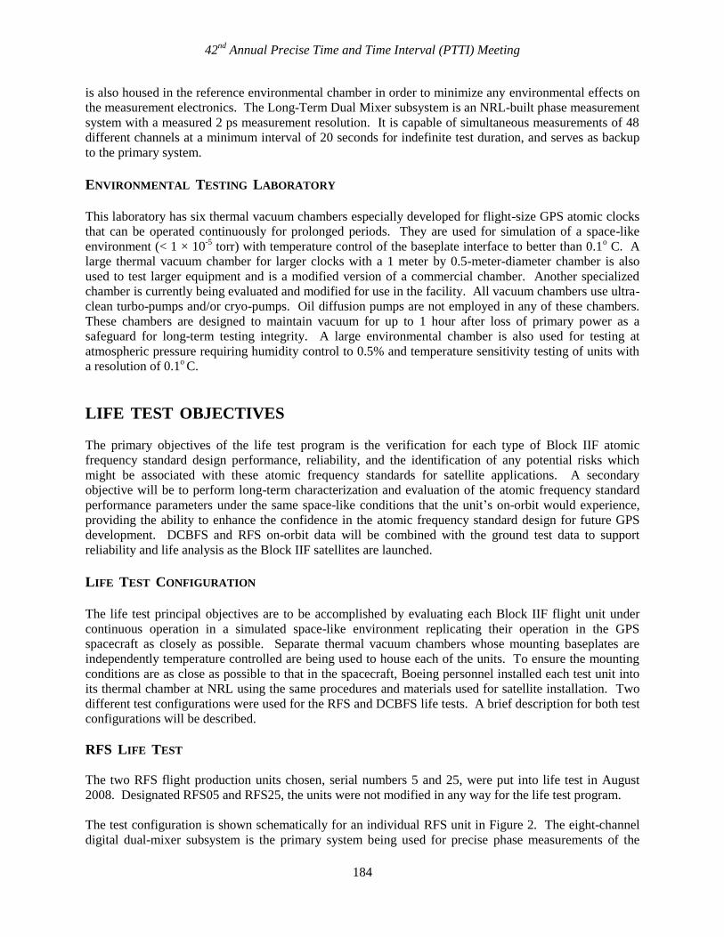
The test configuration is shown schematically for an individual RFS unit in Figure 2. The eight-channel
digital dual-mixer subsystem is the primary system being used for precise phase measurements of the
42nd
Annual Precise Time and Time Interval (PTTI) Meeting
185
output 10.23 MHz signals from each unit with the reference masers at 1-second intervals. These 1-second
measurements are collected and archived for sampling typically at 20 seconds for analysis. The 48-
channel dual-mixer system is being used for redundant measurements and backup. That system is a 5
MHz system and requires the 10.23 MHz signals to be converted to 5 MHz by a Numerically Controlled
Oscillator (NCO) so that they can be input into the Long-Term Channel dual-mixer phase measurement
systems. These data are collected at 20-second intervals and serves as backup should the primary system
experience a temporary outage.
Any of the NRL reference masers, shown in Figure 1, can be employed as the reference for the phase
measurement data. The reference clock used for the data to be shown in this paper is the Symmetricom
hydrogen maser designated N3. It has a frequency stability of approximately 1 × 10-15
at 1 day.
The high-precision 1-second and 20-second phase measurements between the NRL hydrogen masers and
RFS units are collected using dedicated collection systems. High-resolution analog sensors monitor each
unit’s 21 telemetry parameters in addition to nine PCEF environmental parameters, and are collected
every 20 seconds.
Figure 2. IIF RFS life test configuration and list of telemetry monitors.
DCBFS LIFE TEST
In the first test begun for the Block IIF program, two flight production DCBFS units, serial numbers 5
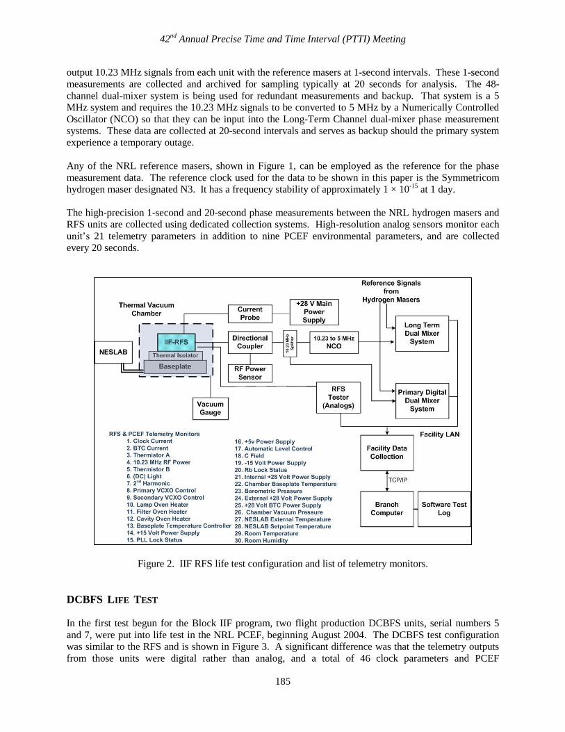
and 7, were put into life test in the NRL PCEF, beginning August 2004. The DCBFS test configuration
was similar to the RFS and is shown in Figure 3. A significant difference was that the telemetry outputs
from those units were digital rather than analog, and a total of 46 clock parameters and PCEF
42nd
Annual Precise Time and Time Interval (PTTI) Meeting
186
environmental parameters were evaluated for each DCBFS unit under test. The DCBFS life test very
quickly uncovered a defect in the high-voltage power supplies used for the ion pump and electron
multiplier functions in the clocks. The first unit, DCBFS07, failed approximately 100 days into the test.
It was repaired and failed again after 21 additional days of operation. The other unit, DCBFS05, had a
continuous run of 591 days before it too experienced a high-voltage power supply failure. The power
supply problem was thoroughly researched and the flight units were modified to prevent future failures.
No other anomalies were found. As of this writing, unit DCBFS05 was returned to NRL in late
November 2010 and preparations to resume the DCBFS life test are underway.
Figure 3. IIF DCBFS life test configuration and list of telemetry monitors.
PERFORMANCE ANALYSIS
The NRL measurement system and references described above form the basis for measuring the signal
phase and frequency of the test clocks. Companion to that system is a network of interconnected data
collection computers for gathering data on the laboratory environmental conditions, test configuration
parameters, and telemetry from the test units. These systems must also operate continuously to capture
the information necessary for analysis. To ensure the existing equipment will capture all the data
generated without any lost data requires a number of data collection computers and redundant systems.
Since the duration of the testing is on the order of years, the collection systems, their controlling software,
and interfacing equipment need to be periodically reevaluated so that replacement equipment may be
employed in the case of failure. The rapid obsolescence of computer equipment makes replacement in
kind a challenge, and new systems often must be developed. The interfaces and data collection software

42nd
Annual Precise Time and Time Interval (PTTI) Meeting
187
are specifically tailored into each test system. This tailoring also applies to the monitoring, programming,
and organization of the relational database and analysis software.
Most of the software used in the facility computer workstations and data collection systems was designed
and coded by NRL personnel. There are no standard products that can accommodate the mix and
complexity of the test units and hardware in the PCEF. Analysis software is also predominately written
by NRL personnel with graphics and networking support provided by commercial products.
RFS PERFORMANCE
The RFS life test data used for analysis in this paper covers the last 140 days of data collected during 22
August 2008 (MJD 54700) to 31 August 2010 (MJD 55439). The phase data consist of continuous 20-
second measurements against the N3 reference. There have been no failures associated with either unit.
The RFS life test units, just as others of this type have done, exhibited an initial phase change
characteristic that has been known as a start-up transient. RFS05 and RFS25 have displayed absolute
frequency offsets of parts in 10-10
. Part of this offset is the nominal -4.45 × 10⁻¹⁰
that is built into GPS
clocks to compensate for relativity. After 2 years of continuous operation, the RFS05 1-day drift offset
has leveled off to -7.5 × 10⁻¹⁴
per day and for RFS25, -3.0 × 10⁻¹⁴
per day [7,8].
The frequency stability presented for each RFS unit, using the Overlapped Hadamard deviation, was
calculated from the phase data. The 1-day frequency stabilities for the RFS life test units are shown in
Figure 4. The stability of RFS05 is just above 2 × 10-15
at 1 day and the stability of RFS25 is just above
3 × 10-15
at 1 day.
Figure 4. Frequency stability of NRL IIF RFS life test.
42nd
Annual Precise Time and Time Interval (PTTI) Meeting
188
NRL ON-ORBIT ANALYSIS
Performance of the GPS clocks is continuously analyzed and evaluated by NRL using a multi-year
database. Continuous 15-minute measurements are collected from a network of 17 ground monitor
stations operated by the U.S. Air Force and the National Geospatial-Intelligence Agency (NGA). NRL
computes the clock estimates for all GPS and monitor station clocks from the GPS monitor station
carrier-derived pseudo-range measurements and NGA-computed precise post-fit orbit ephemerides, and
are referenced to the USNO DoD Master Clock in Washington, D.C. The purpose of the analyses is to
determine the performance of the timing signals originating from the atomic frequency standards onboard
the space vehicles. Metrics used in the analyses include frequency, drift, and frequency stability histories
based on the Allan and Hadamard deviations. The results of the NRL analyses of the space vehicle and
monitor station clocks are used by the GPS MCS to set parameters in the Kalman filter, thereby
improving navigation and time transfer performance [9]. The results are reported on a quarterly basis to
the GPS Frequency Standards Working Group (FSWG), archived, and made available to FSWG members
on a secure NRL Web site [10].
The IGS produces highly accurate and precise GPS ephemeris and clock products in support of
demanding scientific applications using state-of-the-art modeling geodetic techniques. Consisting of over
350 GNSS tracking stations, the IGS network can also track SVs that are not set healthy and many
tracking sites now operate with a significantly smaller data sampling interval. These data are available to
NRL as an independent data source.
BLOCK IIF LAUNCH
On 28 May 2010, the first Block IIF satellite, designated SVN62/PRN25, was launched containing three
atomic frequency standards, one DCBFS Serial Number 1010 (Cs 1010) and two RFS Serial Numbers 27
and 14 (Rb 27 and Rb 14). Only one atomic frequency standard is operated at a time to drive the SV
electronics. Prior to the satellite being set healthy, initial on-orbit testing of the vehicle was conducted
from launch until 25 August 2010. During that time, a series of maneuvers, or delta velocities (Delta-V)
were needed to bring the satellite into its final orbital position. The first frequency standard turned on
was Cs 1010, which was operated from 13 June (MJD 55360) through 12 July 2010 (MJD 55389). The
second and current operational clock turned on was Rb 27. The vehicle was set usable on 27 August 2010
(MJD 55436).
SVN62 Cs 1010
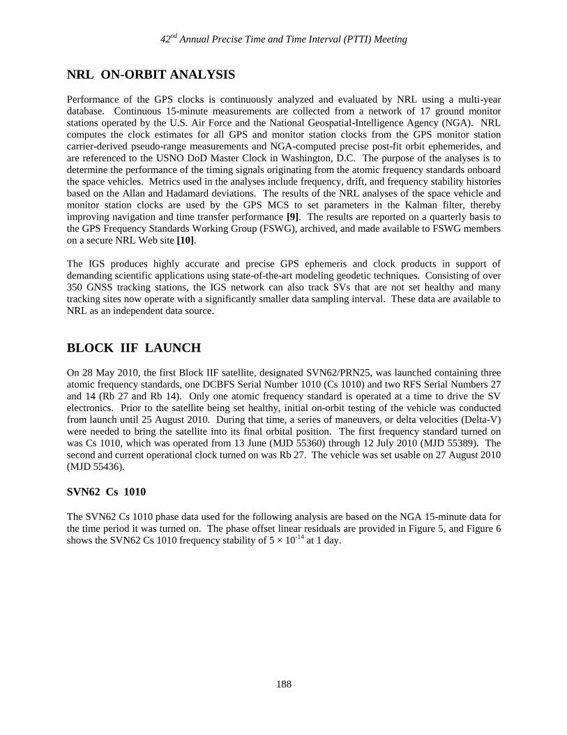
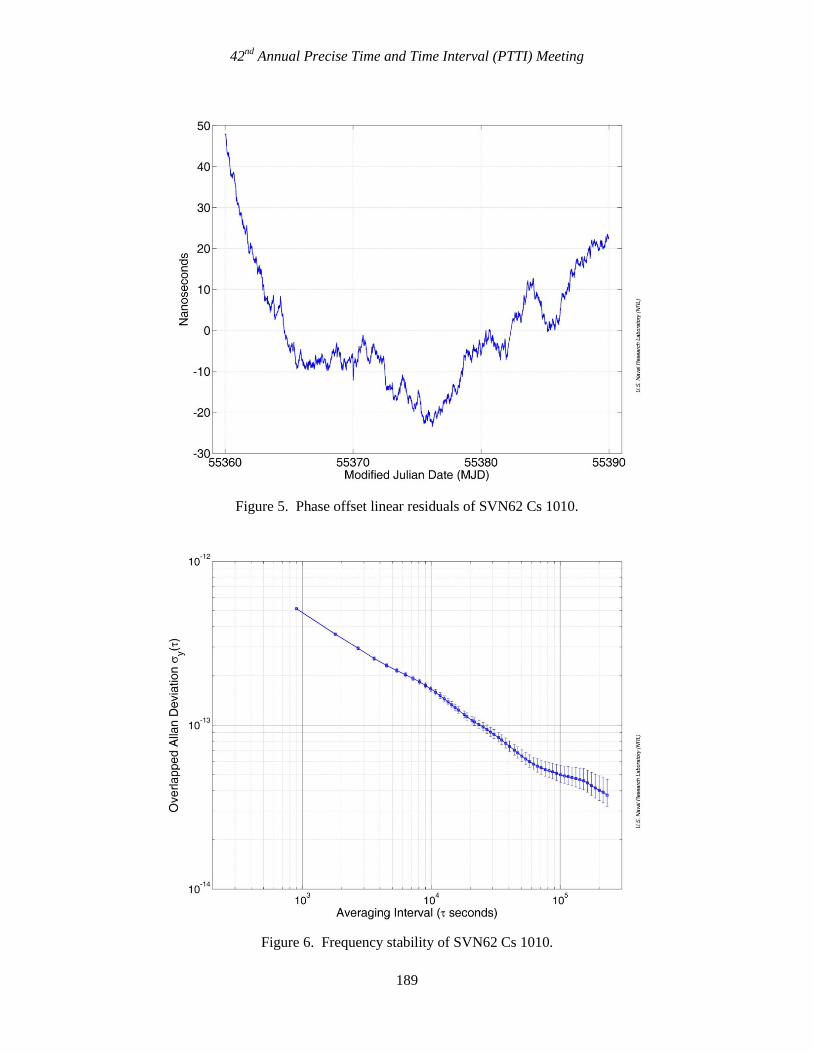
The SVN62 Cs 1010 phase data used for the following analysis are based on the NGA 15-minute data for
the time period it was turned on. The phase offset linear residuals are provided in Figure 5, and Figure 6
shows the SVN62 Cs 1010 frequency stability of 5 × 10-14
at 1 day.
42nd
Annual Precise Time and Time Interval (PTTI) Meeting
189
Figure 5. Phase offset linear residuals of SVN62 Cs 1010.
Figure 6. Frequency stability of SVN62 Cs 1010.
42nd
Annual Precise Time and Time Interval (PTTI) Meeting
190
SVN62 Rb 27
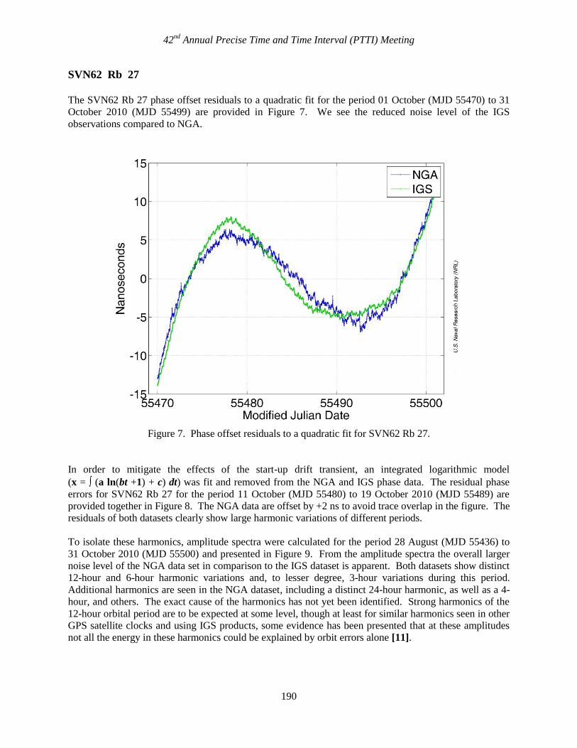
The SVN62 Rb 27 phase offset residuals to a quadratic fit for the period 01 October (MJD 55470) to 31
October 2010 (MJD 55499) are provided in Figure 7. We see the reduced noise level of the IGS
observations compared to NGA.
Figure 7. Phase offset residuals to a quadratic fit for SVN62 Rb 27.
In order to mitigate the effects of the start-up drift transient, an integrated logarithmic model
(x = (a ln(bt +1) + c) dt) was fit and removed from the NGA and IGS phase data. The residual phase
errors for SVN62 Rb 27 for the period 11 October (MJD 55480) to 19 October 2010 (MJD 55489) are
provided together in Figure 8. The NGA data are offset by +2 ns to avoid trace overlap in the figure. The
residuals of both datasets clearly show large harmonic variations of different periods.
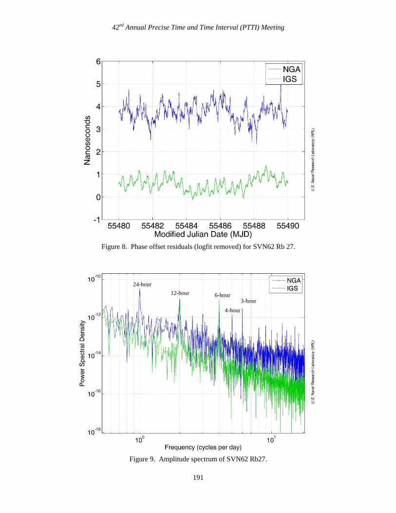
To isolate these harmonics, amplitude spectra were calculated for the period 28 August (MJD 55436) to
31 October 2010 (MJD 55500) and presented in Figure 9. From the amplitude spectra the overall larger
noise level of the NGA data set in comparison to the IGS dataset is apparent. Both datasets show distinct
12-hour and 6-hour harmonic variations and, to lesser degree, 3-hour variations during this period.
Additional harmonics are seen in the NGA dataset, including a distinct 24-hour harmonic, as well as a 4-
hour, and others. The exact cause of the harmonics has not yet been identified. Strong harmonics of the
12-hour orbital period are to be expected at some level, though at least for similar harmonics seen in other
GPS satellite clocks and using IGS products, some evidence has been presented that at these amplitudes
not all the energy in these harmonics could be explained by orbit errors alone [11].
42nd
Annual Precise Time and Time Interval (PTTI) Meeting
191
Figure 8. Phase offset residuals (logfit removed) for SVN62 Rb 27.
Figure 9. Amplitude spectrum of SVN62 Rb27.
4-hour
24-hour
12-hour 6-hour 3-hour
42nd
Annual Precise Time and Time Interval (PTTI) Meeting
192
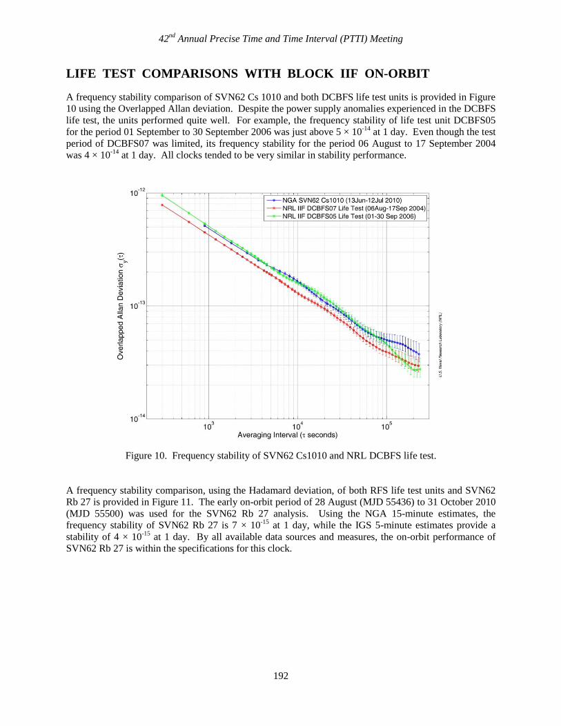
LIFE TEST COMPARISONS WITH BLOCK IIF ON-ORBIT
A frequency stability comparison of SVN62 Cs 1010 and both DCBFS life test units is provided in Figure
10 using the Overlapped Allan deviation. Despite the power supply anomalies experienced in the DCBFS
life test, the units performed quite well. For example, the frequency stability of life test unit DCBFS05
for the period 01 September to 30 September 2006 was just above 5 × 10-14
at 1 day. Even though the test
period of DCBFS07 was limited, its frequency stability for the period 06 August to 17 September 2004
was 4 × 10-14
at 1 day. All clocks tended to be very similar in stability performance.
Figure 10. Frequency stability of SVN62 Cs1010 and NRL DCBFS life test.
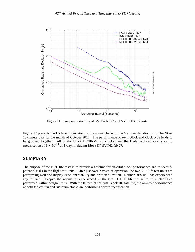
A frequency stability comparison, using the Hadamard deviation, of both RFS life test units and SVN62
Rb 27 is provided in Figure 11. The early on-orbit period of 28 August (MJD 55436) to 31 October 2010
(MJD 55500) was used for the SVN62 Rb 27 analysis. Using the NGA 15-minute estimates, the
frequency stability of SVN62 Rb 27 is 7 × 10-15
at 1 day, while the IGS 5-minute estimates provide a
stability of 4 × 10-15
at 1 day. By all available data sources and measures, the on-orbit performance of
SVN62 Rb 27 is within the specifications for this clock.
42nd
Annual Precise Time and Time Interval (PTTI) Meeting
193
Figure 11. Frequency stability of SVN62 Rb27 and NRL RFS life tests.
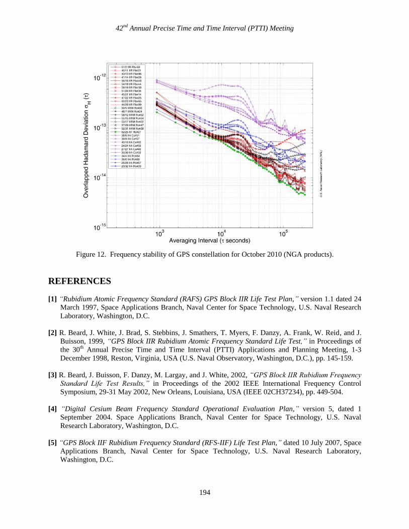
Figure 12 presents the Hadamard deviation of the active clocks in the GPS constellation using the NGA
15-minute data for the month of October 2010. The performance of each Block and clock type tends to
be grouped together. All of the Block IIR/IIR-M Rb clocks meet the Hadamard deviation stability
specification of 6 × 10-14
at 1 day, including Block IIF SVN62 Rb 27.
SUMMARY
The purpose of the NRL life tests is to provide a baseline for on-orbit clock performance and to identify
potential risks in the flight test units. After just over 2 years of operation, the two RFS life test units are
performing well and display excellent stability and drift stabilization. Neither RFS unit has experienced
any failures. Despite the anomalies experienced in the two DCBFS life test units, their stabilities
performed within design limits. With the launch of the first Block IIF satellite, the on-orbit performance
of both the cesium and rubidium clocks are performing within specification.
42nd
Annual Precise Time and Time Interval (PTTI) Meeting
194
Figure 12. Frequency stability of GPS constellation for October 2010 (NGA products).
REFERENCES
[1] “Rubidium Atomic Frequency Standard (RAFS) GPS Block IIR Life Test Plan,” version 1.1 dated 24
March 1997, Space Applications Branch, Naval Center for Space Technology, U.S. Naval Research
Laboratory, Washington, D.C.
[2] R. Beard, J. White, J. Brad, S. Stebbins, J. Smathers, T. Myers, F. Danzy, A. Frank, W. Reid, and J.
Buisson, 1999, “GPS Block IIR Rubidium Atomic Frequency Standard Life Test,” in Proceedings of
the 30th Annual Precise Time and Time Interval (PTTI) Applications and Planning Meeting, 1-3
December 1998, Reston, Virginia, USA (U.S. Naval Observatory, Washington, D.C.), pp. 145-159.
[3] R. Beard, J. Buisson, F. Danzy, M. Largay, and J. White, 2002, “GPS Block IIR Rubidium Frequency
Standard Life Test Results,” in Proceedings of the 2002 IEEE International Frequency Control
Symposium, 29-31 May 2002, New Orleans, Louisiana, USA (IEEE 02CH37234), pp. 449-504.
[4] “Digital Cesium Beam Frequency Standard Operational Evaluation Plan,” version 5, dated 1
September 2004. Space Applications Branch, Naval Center for Space Technology, U.S. Naval
Research Laboratory, Washington, D.C.
[5] “GPS Block IIF Rubidium Frequency Standard (RFS-IIF) Life Test Plan,” dated 10 July 2007, Space
Applications Branch, Naval Center for Space Technology, U.S. Naval Research Laboratory,
Washington, D.C.
42nd
Annual Precise Time and Time Interval (PTTI) Meeting
195
[6] R. Beard, O. Oaks, K. Senior, and J. White, 2010, “Timing Activities at the U.S. Naval Research
Laboratory,” in Proceedings of the 41st Annual Precise Time and Time Interval (PTTI) Applications
and Planning Meeting, 16-19 November 2009, Santa Ana Pueblo, New Mexico, USA (U.S. Naval
Observatory, Washington, D.C.), pp. 283-292.
[7] F. Vannicola, R. Beard, J. White, K. Senior, A. Kubik, D. Wilson, and J. Buisson, 2010, “GPS Block
IIF Rubidium Frequency Standard Life Test,” in Proceedings of the 41st Annual Precise Time and
Time Interval (PTTI) Applications and Planning Meeting, 16-19 November 2009, Santa Ana Pueblo,
New Mexico, USA (U.S. Naval Observatory, Washington, D.C.), pp. 449-456.
[8] F. Vannicola, R. Beard, J. White, K. Senior, A. Kubik, and D. Wilson, 2010, “GPS Block IIF
Rubidium Frequency Life Test,” in Proceedings of the ION Satellite System Conference, 21-24
September 2010, Portland, Oregon, USA (Institute of Navigation, Alexandria, Virginia), pp. 812-819.
[9] S. Hutsell, W. Reid, J. Crum, H. Mobbs, and J. Buisson, 1997, “Operational Use of the Hadamard
Variance in GPS,” in Proceedings of the 28th Annual Precise Time and Time Interval (PTTI)
Applications and Planning Meeting, 3-5 December 1996, Reston, Virginia, USA (U.S. Naval
Observatory, Washington, D.C.), pp. 201-214.
[10] O. Oaks, J. Buisson, and M. Largay, 2008, “A Summary of the GPS Constellation Clock
Performance,” in Proceedings of the 39th Annual Precise Time and Time Interval (PTTI)
Applications and Planning Meeting, 26-29 November 2007, Long Beach, California, USA (U.S.
Naval Observatory, Washington, D.C.), pp. 119-129.
[11] K. Senior, J. Ray, and R. Beard, 2008, “Characterization of periodic variations in the GPS satellite
clocks,” in GPS Solutions, 12, no. 3, 211-225.
42nd
Annual Precise Time and Time Interval (PTTI) Meeting
196
![Web view15.10.2015 · -ValueMergeType 'Update' ` ... -Expression 'IIF(IsPresent([cloudSourceAnchor]), IIF(Word](https://img.pdfslide.us/doc/110x75/5a9e34d57f8b9a0d7f8ba421/web-view15102015-valuemergetype-update-expression-iifispresentcloudsourceanchor.jpg)


![;;.iif' Paper ID[ C 8305]](https://img.pdfslide.us/doc/110x75/6256e8dccd6bb25972726384/iif-paper-id-c-8305.jpg)