Embed Size (px)
Citation preview
Page i
CALCULATION COVER SHEET
Calcul ation No: PTN-BFJH-96-005
Title: Fire Barrier Am acit Correction Factors - Extra olation of Test
Results for 3 Hour Barrier
No.
Original Issue
Descri tion By
!l(~
Date Chkd Date Appr Date
REV IS IONS
Form 82A, Rev 6/94
9hi2260324 9hi2i9PDR ADQCK 05000335P PDR

Page ii
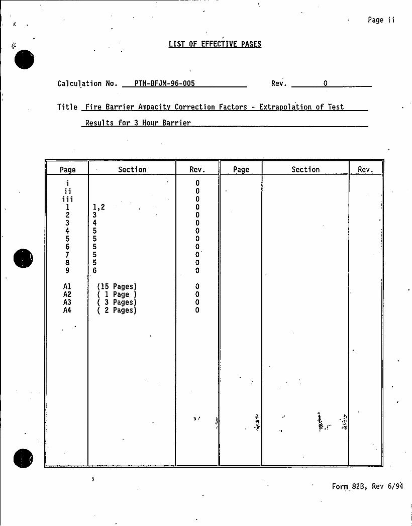
LIST OF EFFECTIVE PAGES
Calculation No. PTN-BFJM-96-005 Rev.
Title Fire Barrier Am acit Correction Factors - Extra olation of Test
Results for 3 Hour Barrier
Pa e
1
ll111
1
23456789
1,234555556
Section Rev.
0000000000'
0
Pa e Section Rev.
A1A2A3A4
15 Pages)1 Page )3 Pages)2 Pages)
Form 82B, Rev 6/94

Page iii
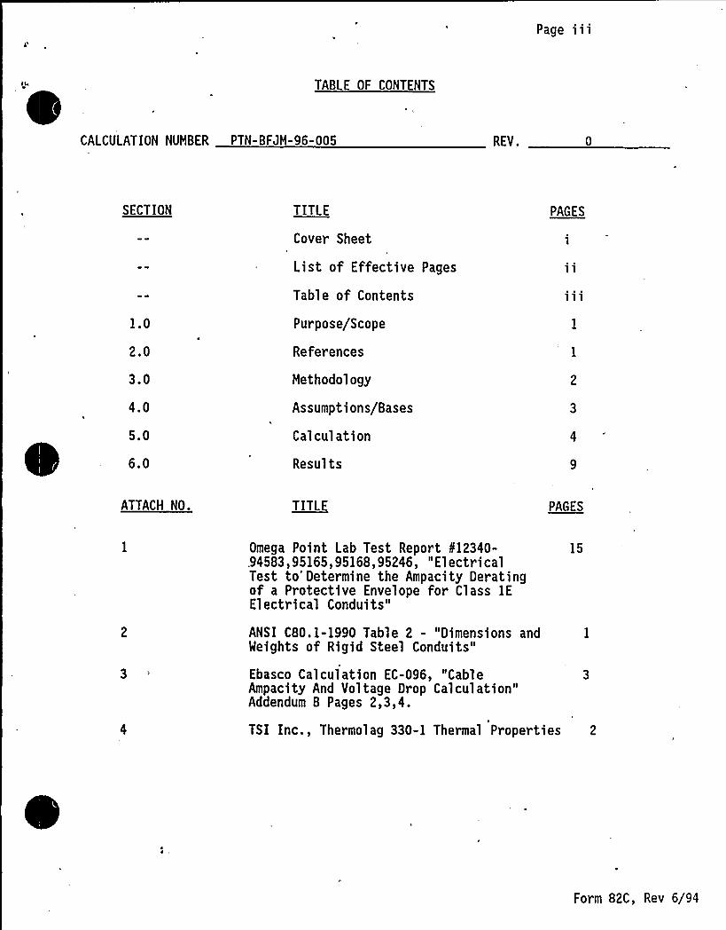
TABLE OF CONTENTS
CALCULATION NUMBER PTN-BFJM-96-005 REV.
SECTION
1.0
2.0
3.0
4.0
5.0
6.0
TITLE
Cover Sheet
List of Effective Pages
Table of Contents
Purpose/Scope
References
Methodology
Assumptions/Bases
Calculation
Results
PAGES
ATTACH NO. TITLE PAGES
Omega Point Lab Test Report kl2340-.94583,95165,95168,95246, "ElectricalTest to'etermine the Ampacity Deratingof a Protective Envelope for Class 1EElectrical Conduits"
ANSI C80. 1-1990 Table 2 - "Dimensions andWeights of Rigid Steel Conduits"
Ebasco Calculation EC-096, "CableAmpacity And Voltage Drop Calculation"Addendum B Pages 2,3,4.
15
TSI Inc., Thermolag 330-1 Thermal Properties 2
Form 82C, Rev 6/94
CALCULATION SHEET
REV' SHEET NO.
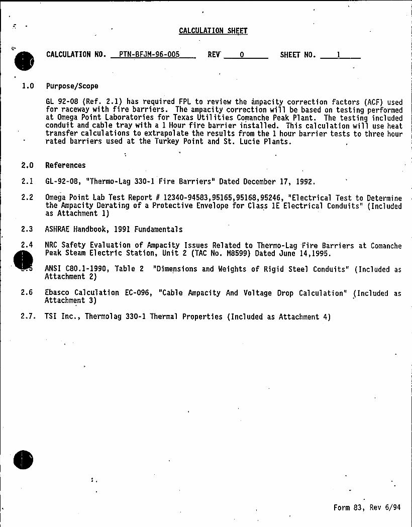
1.0 Purpose/Scope
GL 92-08 (Ref. 2. 1) has required FPL to review the ampacity correction factors (ACF) usedfor raceway with fire barriers. The ampacity correction will be based on testing performedat Omega Point Laboratories for Texas Utilities Comanche Peak Plant. The testing includedconduit and cable tray with a 1 Hour fire barrier installed. This calculation will use heattransfer calculations to extrapolate the results from the 1 hour barrier tests to three hourrated barriers used at the Turkey Point and St. Lucie Plants.
2.0 References
2. 1 GL-92-08, "Thermo-Lag 330-1 Fire Barriers" Dated December 17, 1992.
2.2 Omega Point Lab Test Report ¹ 12340-94583,95165,95168,95246, "Electrical Test to Determinethe Ampacity Derating of a Protective Envelope for Class lE Electrical Conduits" (Includedas Attachment 1)
2.3 ASHRAE Handbook, 1991 Fundamentals
2.4 NRC Safety Evaluation of Ampacity Issues Related to Thermo-Lag Fire Barriers at ComanchePeak Steam Electric Station, Unit 2 (TAC No. H8599) Dated June 14, 1995.
ANSI C80. 1-1990, Table 2 "Dimensions and Weights of Rigid Steel Conduits" ( Included asAttachment 2)
2.6 Ebasco Calculation EC-096, "Cable Ampacity And Voltage Drop Calculation" ( Included asAttachment 3)
2.7. TSI Inc., Thermolag 330-1 Thermal Properties (Included as Attachment 4)
Form 83, Rev 6/94
CALCULATION SHEET
I;
CALCULATION NO. PTN- BFJM-96-005 REV 0 SHEET NO.
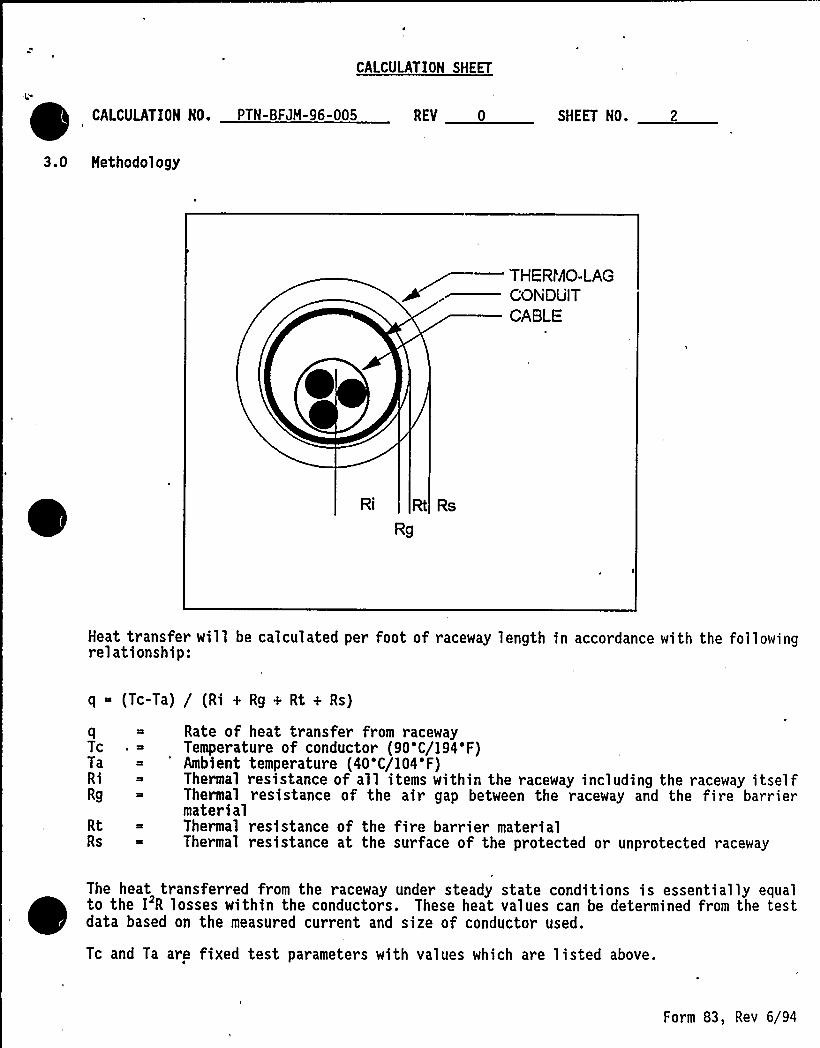
3.0 Methodology
—THERI'AO-LAGCONDUITCABLE
Ri Rt Rs
Rg
Heat transfer will be calculated per foot of raceway length in accordance with the followingrelationship:
q (Tc-Ta) / (Ri + Rg + Rt + Rs)
qTcTaRiRg
RtRs
Rate of heat transfer from racewayTemperature of conductor (90'C/194'F)Ambient temperature (40'C/104'F)Thermal resistance of all items within the raceway including the raceway itselfThermal resistance of the air gap between the raceway and the fire barriermaterialThermal resistance of the fire barrier materialThermal resistance at the surface of the protected or unprotected raceway
The heat transferred from the raceway under steady state conditions is essentially equalto the I'R losses within the conductors. These heat values can be determined from the testdata based on the measured current and size of conductor used.
Tc and Ta are fixed test parameters with values which are listed above.
Form 83, Rev 6/94
CALCULATION SHEET
0 CALCULATION NO. PTN- BFJH-96-005 REV 0 SHEET NO.
The thermal resistance values will be determined based on test data and physical propertiesas follows:
Ri will be calculated from the test data for raceway without fire barrier
Rg will be calculated from the test data for raceway with a I hour barrier
Rt will be calculated based on the known thermal conductivity (k) for The~mn-Lag
Rs will be based un known physical properties considering convection arid radiation heattransfer.
After all of the thermal resistance values have been established, the heat transferred canbe calculated for the raceway with the three hour barrier.
Since the heat is a function of the current squared, the ampacity correction factor (ACF)will be determined by the following relationship.
ACF I/I V(q,~q where the subscript p refers to the protected raceway
4.2
4.3
4.4
4.5
4.6
Assumptions/Bases
The effect of inductive losses in the raceway and cable sheath will be negligible withrespect to applying the test data to the Turkey Point and St. Lucie configurations,
Surface emittance for cable, raceway, and Thermo-Lag will be assumed to be equal to 0.9.Note that a high emittance value will reduce the thermal resistance at the surface havingan overall effect of maximizing the ampacity de-rating.
Heat transfer through the sides of cable tray will be assumed to be zero. This will reducethe heat transfer equation for tray to a one dimensional heat transfer equation. As thetested cable tray is relatively wide ,24", this is expected to be a good approximation forall cable tray.
One hour Thermo-Lag fire barrier will be assumed to be at the minimum thickness of 1/2"(I/4" for overlay where used). This thickness will provide a conservative value whencalculating the R value for the gap between the raceway and the barrier.
Three hour Thermo-Lag fire barrier will be assumed to be at the nominal thickness inaccordance with the manufacture's tolerance, l-l/4 inches. This thickness'will provide aconservative result when calculating the heat transferred with the three hour barrier, asthe value of the initial I hour wrap was minimized. It was judged to be unrealisticallyconservative to go to the maximum thickness tolerance of 1.5 inches.
Raceway is made of rigid steel, magnetic material, which is typical for power plantinstallations.
Banked conduit which is banked in a single plane can be assumed to be equivalent to cabletray. Both configurations involve a cable mass arranged in a shallow rectangular section.Both configurations involve an air gap between the cables and the fire barrier material.
Form 83, Rev 6.'94
CALCULATION SHEET
CALCULATION NO. PTN- BFJN-96-005 REV 0 SHEET NO. 4
4.8 The thermal resistance values for all items within the raceway and for the gap between theconduit and the Thermolag material will be assumed to remain constant as additionalthickness of Thermolag is installed. Considering that the geometry of these areas is notchanged, this approximation is reasonable for the purpose of extrapolating the thermalresistance from raceway with 1 hour wrap to raceway with 3 hour wrap.
5.0 Calculation
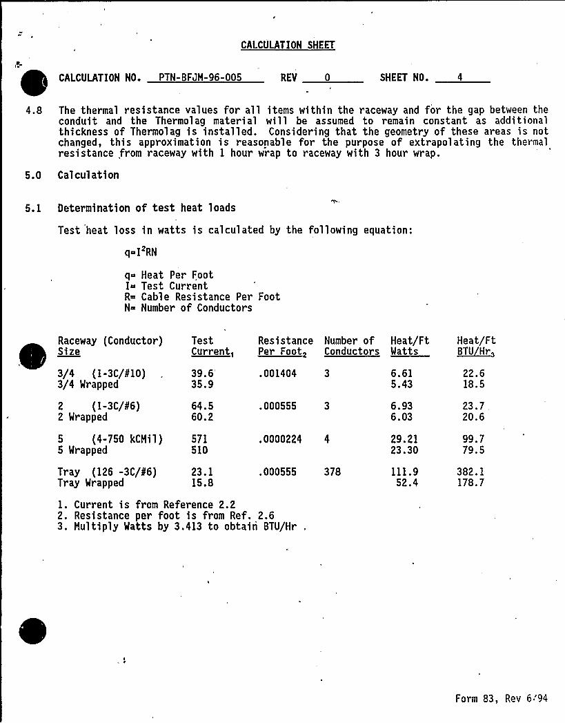
5. 1 Determination of test heat loads
Test heat loss in watts is calculated by the following equation:
q IRN
q Heat Per FootI Test CurrentR Cable Resistance Per FootN Number of Conductors
Raceway (Conductor)Size
3/4 (I-3C/0'10)3/4 Wrapped
TestCurrent,
39.6'5.9 .001404 6.615.43
22.618.5
Resistance Number of Heat/Ft Heat/FtPer Foot, Conductors Watts ~BTU Hr
2 (I-3C/86)2 Wrapped
64.560.2
.000555 3 6.936.03
23.7 .
20.6
5 (4-750 kCMil) 5715 Wrapped 510
.0000224 4 29.2123.30
99.779.5
Tray (126 -3C/86)Tray Wrapped
23.115.8
.000555 378 111.952.4
382.1178.7
1. Current is from Reference 2.22. Resistance per foot is from Ref. 2.63. Hultiply Watts by 3.413 to obtain BTU/Hr
Form 83, Rev 6'94
CALCULATION SHEET
CALCULATION NO. PTN- BFJH-96-005 REV 0 SHEET NO.
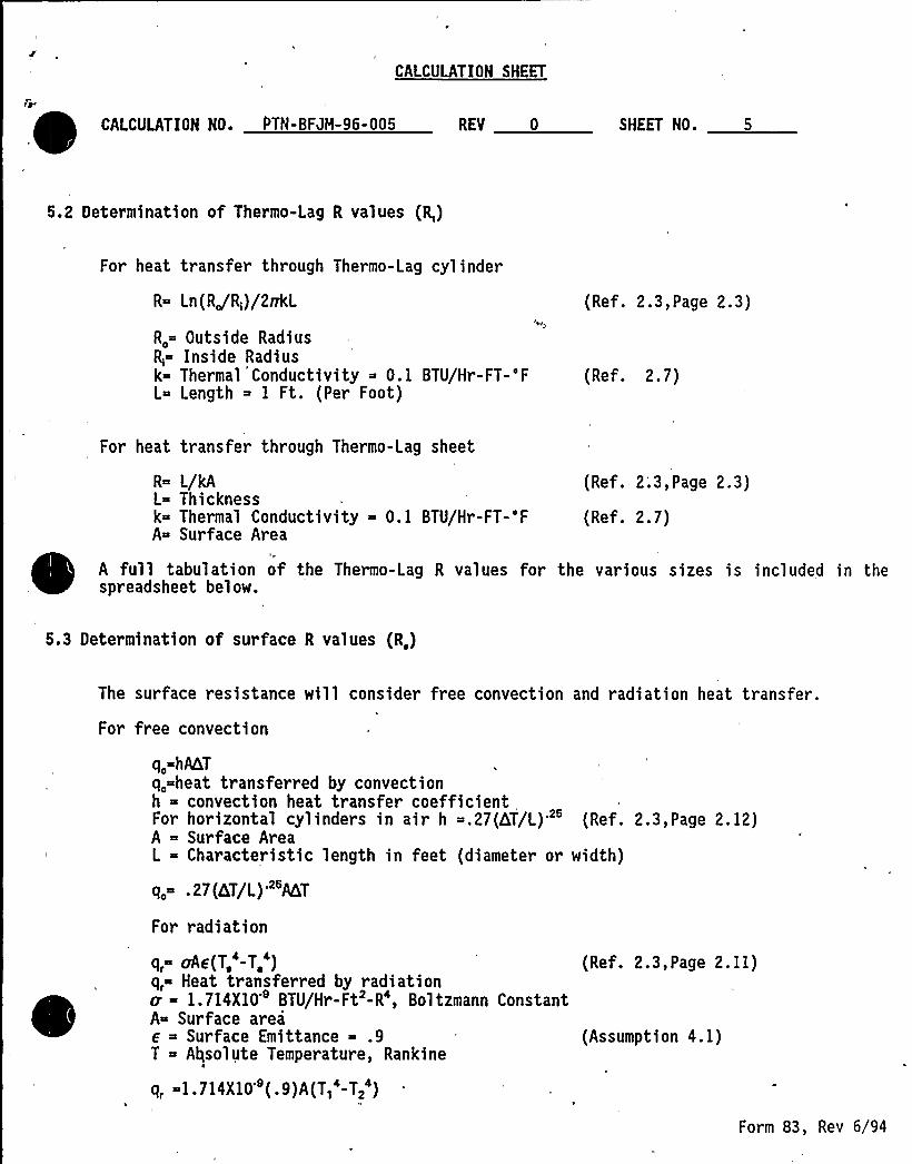
5.2 Determination of Thermo-Lag R values (R,)
For heat transfer through Thermo-Lag cylinder
R Ln(RJR;)/2vkL
R. Outside RadiusR; Inside Radiusk- Thermal Conductivity 0. 1 BTU/Hr-FT-'FL Length 1 Ft. (Per Foot)
(Ref. 2.3,Page 2.3)
(Ref. 2.7)
For heat transfer through Thermo-Lag sheet
(Ref. 2.7)
R L/kA (Ref. 2'.3,Page 2.3)L Thicknessk Thermal Conductivity 0. 1 BTU/Hr-FT-'FA Surface Area
N
A full tabulation of the Thermo-Lag R values for the various sizes is included in thespreadsheet below.
5.3 Determination of surface R values (R,)
The surface resistance will consider free convection and radiation heat transfer.
For free convection
q, hAKT
q, heat transferred by convectionh - convection heat transfer coefficientFor horizontal cylinders in air h .27(hT/L)'" (Ref. 2.3,Page 2. 12)A - Surface AreaL - Characteristic length in feet (diameter or width)
q, .27(4T/L)"MT
For radiation
q, ohe(T, -T, )q, Heat transferred by radiation0 1.714X10 BTU/Hr-Ft -R', Boltzmann ConstantA Surface area
Surface Emittance .9T Absolute Temperature, Rankine
q, -1.714X10'(.9) A(T,'-T,')
(Ref. 2.3,Page 2. 11)
(Assumption 4. 1)
Form 83, Rev 6/94
CALCULATION SHEET
CALCULATION NO. PTN- BFJM-96-005 REV 0 SHEET NO. 6
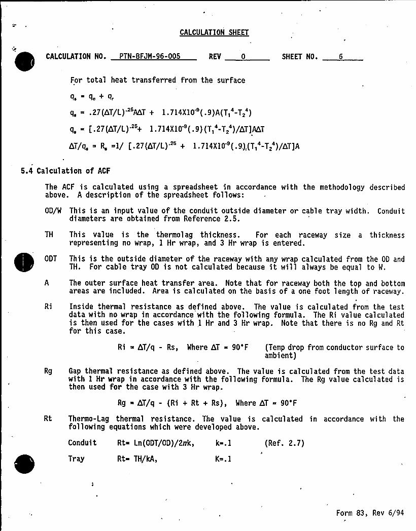
For total heat transferred from the surface
q, - q, + q,
q, ~ .27(QT/L)'T + 1.714X10 (.9)A(T, -T2 )
q, = [.27(bT/L)' 1.714X10 (.9)(T, -T, )/QT]AbT
GT/q, R, 1/ t,.27(GT/L) " + 1.714X10'(.9.) (T,'-T,')/LT]A
5.4 Calculation of ACF
The ACF is calculated using a spreadsheet in accordance with the methodology describedabove. A description of the spreadsheet follows:
OD/W This is an input value of the conduit outside diameter or cable tray width. Conduitdiameters are obtained from Reference 2.5.
TH This value is the thermolag thickness. For each raceway size a thicknessrepresenting no wrap, 1 Hr wrap, and 3 Hr wrap is entered.
ODT This is the outside diameter of the raceway with any wrap calculated from the 00 andTH. For cable tray OD is not calculated because it will always be equal to W,
A The outer surface heat transfer area. Note that for raceway both the top and bottomareas are included. Area is calculated on the basis of a one foot length of raceway.
Ri Inside thermal resistance as defined above. The value is calculated from the testdata with no wrap in accordance with the following formula. The Ri value calculatedis then used for the cases with 1 Hr and 3 Hr wrap. Note that there is no Rg and Rtfor this case.
Ri hT/q - Rs, Where hT = 90'F (Temp drop from conductor surface toambient)
Rg Gap thermal resistance as defined above. The value is calculated from the test datawith 1 Hr wrap in accordance with the following formula. The Rg value calculated isthen used for the case with 3 Hr wrap.
Rg bT/q - (Ri + Rt + Rs), Where hT - 90'F
Rt Thermo-Lag thermal resistance. The value is calculated in accordance with thefollowing equations which were developed above.
Conduit Rt Ln(ODT/OD)/2vk, k . 1 (Ref. 2.7)
Tray Rt TH/kA, K .1
Form 83, Rev 6/94r
CALCULATION SHEET
CALCULATION NO. PTN- BFJH-96-005 REV 0 ,SHEET NO. 7
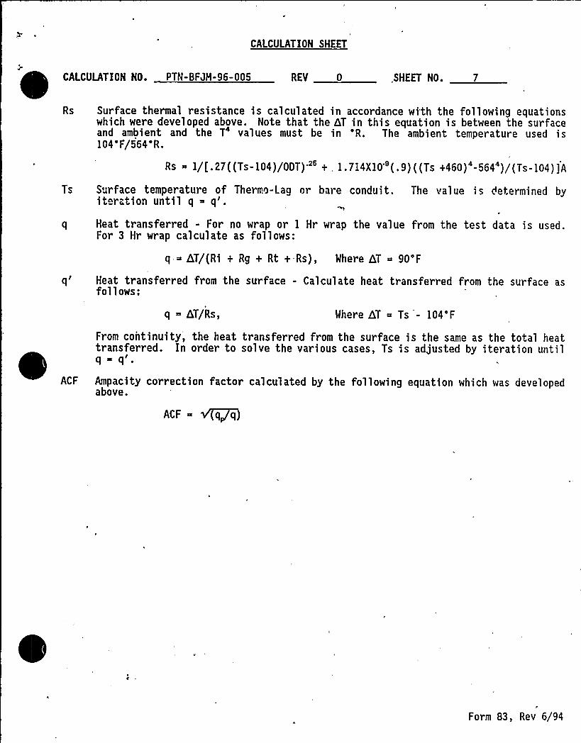
Rs Surface thermal resistance is calculated in accordance with the following equationswhich were developed above. Note that the hT in this equation is between the surfaceand ambient and the T4 values must be in 'R. The ambient temperature used is104'F/564'R.
Rs 1/[.27((Ts-104)/ODT)" + 1.714X10'.9)((Ts +460)'-564')/(Ts-104)]A
Ts Surface temperature of Thermo-Lag nr bare conduit. The value is determined byiteration until q q'.
q Heat transferred - For no wrap or 1 Hr wrap the value from the test data is used.for 3 Hr wrap calculate as follows:
q hT/(Ri + Rg + Rt +-Rs), Where hT 90'F
q'eat transferred from the surface - Calculate heat transferred from the surface asfollows:
q - hT/Rs, Where hT Ts - 104'F
From continuity', the heat transferred from the surface is the same as the total heattransferred. In order to solve the various cases, Ts is adjusted by iteration until
ACF Ampacity correction factor calculated by the following equation which was developedabove.
ACF v (q,~q
Form 83, Rev 6/94
PTN-BFJM-96-005Revision 0
Page8of 9
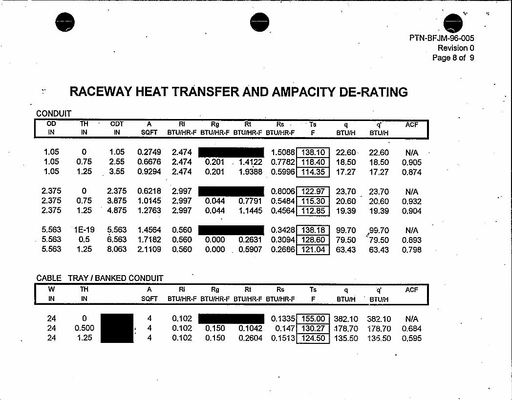
RACEWAYHEAT TRANSFER AND AMPACITYDE-RATING
CONDUITODIN
THIN
ODTIN
A Ri Rg Rt Rs - TsSQFT BTU/HR-F BTU/HR-F BTU/HR-F BTU/HR-F F BTU/H BTU/H
ACF
1.05 0 1.05 0.2749 2.474 1.50881.05 0.75 2.55 0.6676 2.474 0.201 . 1.4122 0.77821.05 1.25 3.55- 0.9294 2.474 0.201 1.9388 0.5996
138.10118.40114.35
22.60- 22.60 NIA18.50 18.50 0.90517.27 17.27 0.874
2.375 0 2.375 0.6218 2.997 0.80062.375 0.75 3.875 1.0145 2.997 0.044 0.7791 0.54842.375 1.25 4.875 1.2763 2.997 0.044 1.1445 0.4564
122.97115.301'12.85
23.70 23.70 N/A20.60 20.60 0.93219.39 19.39 0.904
5.563 1E-19 5.563 1.4564 0.560 0.34285.563 0.5 6.563 1.7182 0.560 0.000 0.2631 0.30945.563 1.25 8.063 2.1109 0.560 0.000 0.5907 0.2686
138.18128.60121.04
99.70,99.70 NIA79.50 79.50 0.89363.43 63.43 0.798
CABLE TRAYI BANKEDCONDUITW TH A Ri Rg Rt Rs Ts
IN IN SQFT BTU/HR-F BTU/HR-F BTU/HR-F BTU/HR-F F BTU/H BTU!H
ACF
24 024 0.50024 1.25
4c 4
4
0.102 0.13350.102 0.150 0.1042 0.1470.102 0.150 0.2604 0.1513
155.00130.27124.50
382.10 382.10 N/A178.70 I 78.70 0.684135.50 135.50 0.595

0
CALCULATION SHEET
CALCULATION NO. PTN- BFJH-96-005
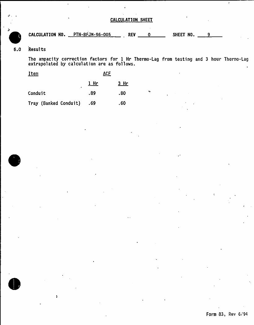
6.0 Results
REV 0 SHEET NO.
The ampacity correction factors for I Hr Thermo-Lag from testing and 3 hour Thermo-Lagextrapolated by calculation are as follows.
Item
Conduit
1 Hr
.89
ACF
3 Hr
.80
Tray (Banked Conduit) .69 .60
Form 83, Rev 6:94

PTN- BFJH-96-005ATTACHMENT IREVISION, 0
PAGE I of 15
AMPACITY DEBATING OFFlRE PROTECTED CABLES
Project No. 12343-94583,95165-95168,95246
ELECTRICALTEST TO DETERMINE THE AMPACITYDERATINGOF APROTECTIVE ENVELOPE FOR CLASS 1E ELECTRICAL
CIRCUITS
March 19, 1993
Prepared For:
TU ElectricCOMQICHE PEAK STEAM ELECTRIC STATION
P.O. Box 1002Glen Rose, Texas 76043-1002
p ppcp)ypD OCT 2 0 f993
~~A PpC~
0
ro'hara

Report No. 12340-94583,95165-95168/5246Texas Utilities Electric
,PTN-BFJH-96-005ATTACHHENT 1
REVISION 0PAGE 2 of 15
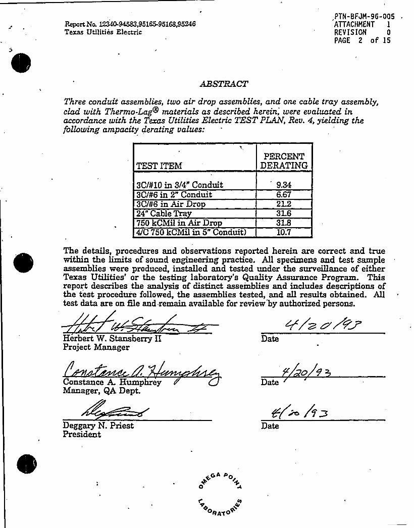
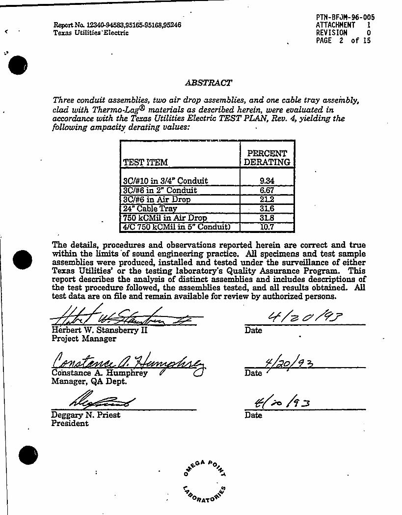
Three conduit assemblies, two air drop assemblies, and one cable tray assembly,clad with Thermo-Lag materials as described herein,'ere evaluated inaccordance with the Texas Utilities Electric TEST PLAN, Rev. 4, yielding thefollowing ampacity derating values:
TEST ITEM
3C/¹10 in 3/4" Conduit3C/¹6 in 2" Conduit3C/¹6 in AirDrop24" Cable Tra750 kCMilin AirDro4/C 750 kCMilin 5" Conduit)
PERCENTDERATING
9.346.67
31.631.810.7
The details, procedures and observations reported herein are correct and truewithin the limits of sound engineering practice. All specimens and test sampleassemblies were produced, installed and tested under the surveillance of eitherTexas Utilities'r the testing laboratory's Quality Assurance Program. Thisreport describes the analysis of distinct assemblies and includes descriptions ofthe test procedure followed, the assemblies tested, and all results obtained. Alltest data are on Gle and remain available for review'by authorized persons.
Herbert W Stansberry HProject Manager
Date
Constance A. HumphreyManager, QA Dept.
Date
Deggary N. PriestPresident
Date
Report, Ne. 12340-94583,95165-95168@5246Texas Utilities Electric
PTN-BFJH-96-005ATTACHMENT 1
REV IS10N 0
PAGE 3 of 15
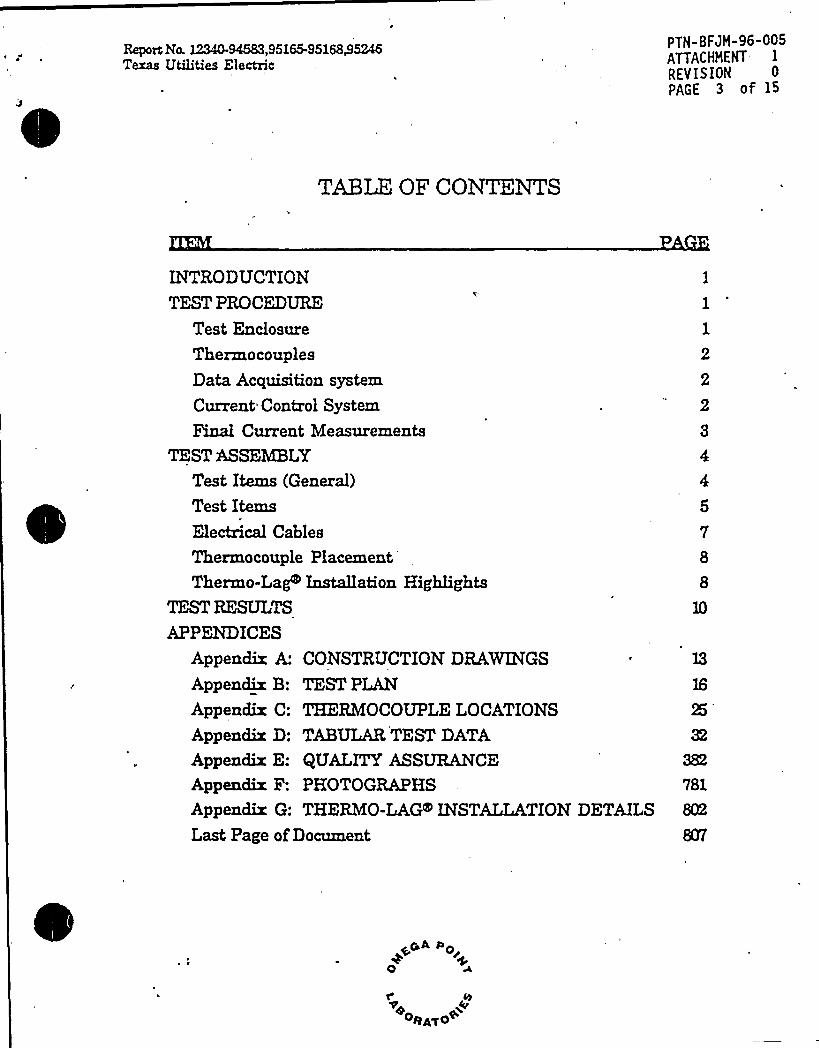
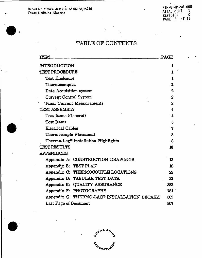
TABLE OF CONTENTS
INTRODUCTIONTEST PROCEDURE
Test Enclosure
Thermo couples
Data Acquisition system
Current Control System
Final Current Measurements
TEST ASSEMBLYTest Items (General)
Test ItemsElectrical Cables
Thermocouple PlacementThermo-Lag Installation Highlights
TEST RESULTS
APPENDICES
Appendix A: CONSTRUCTION DRAWINGS
Appendix B: TEST PLANAppendix C: THERMOCOUPLE LOCATIONSAppendix D: TABULA,TEST DATAAppendix E: QUALITYASSURANCEAppendix F: PHOTOGRAPHS
Appendix G: THERMO-LAG INSTALLATIONLast Page ofDocument
1
1
2
2
2
3
4
5
7
8
8
10
]3
16
25
32
382
781
DETAILS 802
8%
OQAyo+
Report No. 12340-94583,95165-95168/5246Texas Utilities Electric
PTN-BFJH-96-005ATTACHMENT IRE'Y IS ION 0PAGE 4 of 15
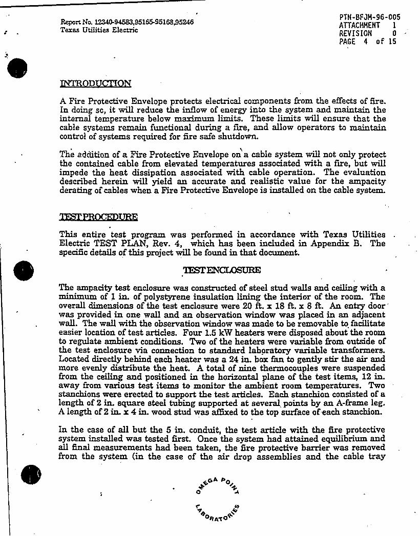
A Fire Protective Envelope protects electrical components from the eQ'ects of fire.In doing sc, it vriQ reduce the inQow of energy into the system and maintain theinternal temperature below maximum limits. These limits will ensure that thecable systems remain functional during a fire, and allow operators to maintaincontrol of systems required for fire safe shutdown.
The addition of a Are . rotective Envelope on a cable system willnot only protectthe contained cable from elevated temperatures associated with a fire, but willimpede the heat dissipation associated with cable operation. The evaluationdescribed herein will yield aa accurate and realistic value for the ampacityderatiag of cables when a Fire Protective Envelope is iastaQed on the cable system.
This entire test prolpmn was performed in accordance with Texas UtilitiesElectric TEST PLAN, Rev. 4, which has been included in Appendix B. Thespecific details of this project wiQ be found in that document.
TEAENCLOSURE
The ampacity test enclosure was constructed of steel stud waQs and ceiling with aminunum of I in. of polystyrene insulatioa liaing the interior of the room. TheoveraQ dimensions of the test enclosure were 20 ft. x 18 &. x 8 ft. An entry doorwas provided in oae wall and an observation window was placed in an adjacentwaQ. The waQ with the observation window was made to be removable to facilitateeasier location of test articles. Four 1.5 kW heaters were disposed about the roomto regu1ate ambient conditions. Two of the heaters were vaxiable from outside ofthe test enclosure via connection to standard laboratory variable transformers.Located directly behind each heater was a 24 in. box fan to gently stir the air andmore evenly distribute the heat. A total of nine thermocouples were suspendedfrom the ceiling and positioned ia the horizontal plane of the test items, 12 in.away Epsom various test items to monitor the ambient room temperatures. Twostanchions were erected to support the test articles. Each staachion consisted of alength of 2 in. square steel tubing supported at several points by an A-frame leg.A length of2 in. x 4 in. wood stud was aQixed to the top surface of each stanchion.
In the case of all but the 5 ia. conduit, the test article with the fire protectivesystem installed was tested first. Once the system had attained. equilibrium andaQ final measurements h'ad been tatea, the fire protective barrier was removedfrom the system (in the case of the air drop assemblies and the cable tray
Report No. 12340-94583,95165-95168/5246Texas Utilities Electric
PTN-BFJH-96-005ATTACHHENT IREV IS IQN 0
PAGE 5 of l5
assembly) or the instrumented cable was removed from the clad conduit andinserted into a similarly constructed, bare conduit.
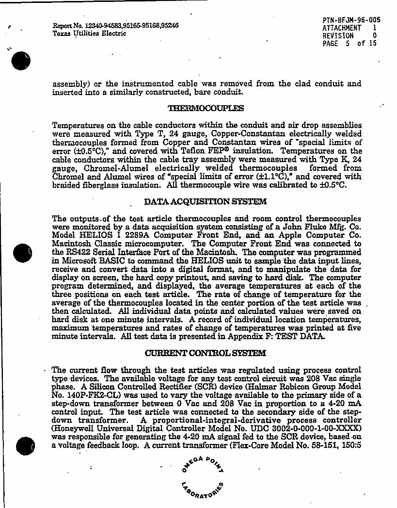
THERMOCOUPUK
Temperatures on the cable conductors within the conduit and air drop assemblieswere measured with Type T, 24 gauge, Copper-Constantan electrically weldedthermocouples formed from Copper and Constantan wires of special limits oferror (&.5'C)," and covered with TeQon FEY insulation. Temperatures on thecable conductors within the cable tray assembly were measured with Type K, 24gauge, Chromel-Alumel electrically welded thermocouples formed fromChromel and Alumel wires of "special limits of error (21.1'C)," and covered withbraided fiberglass insulation. All thermocouple wire was calibrated to &.5'C.
DATAACQUXSZZXONSYSTEM
The outputs-of the test article thermocouples and room control thermocoupleswere monitored by a data acquisition system consisting of a John Fluke Mfg. Co.Model HELIOS I 2289A Computer Front End, and an Apple Computer Co.Macintosh Classic microcomputer. The Computer Front End was connected tothe RS422 Serial Interface Port of the Macintosh. The computer was prograxnmedin Microsoft BASIC to command the HELIOS unit to sample the data input lines,receive and convert data into a digital format, and to manipulate the data fordisplay on screen, the hard copy printout, and saving to hard disk. The computerprogram determined, and displayed, the average temperatures at each of thethree positions on each test article. The rate of change of temperature for theaverage of the thermocouples located in the center portion of the test article was.then calculated. All individual data points and calculated values were saved onhard disk at one minute intervals. A record of individual location temperatures,maximum temperatures and rates of change of temperatures was printed at fiveminute intervals. Alltest data is presented in Appendix F: TEST DATA.
CONTROL SYSTEM
The current Qow through the test articles was regulated using process controltype devices. The available voltage for any test control circuit was 208 Vac singlephase. A Silicon Controlled RectIfier (SCR) device (Halmar Robicon Group ModelNo. 140P-FK2-CL) was used to vaxy the voltage available to the primary side of astep-down transformer between 0 Vac and 208 Vac in proportion to a 4-20 mAcontrol input. The test article was connected to the secondary side of the step-down transformer. A proportional-integral-derivative process controller(Honeywell Universal Digital Controller Model No. UDC 3002-0-000-1-00-XXXK)was responsible for generating the '4-20 mA signal fed to the SCR device, based ona voltage feedback loop. A current transforxner (Flex-Core Model No. 58-151, 150:5
a "oJ~
0
Cy
oRAxo

0
Report Na. 12340-94583,95165-95168@5246Texas Utilities Electric
PTN-BFJH-96-005ATTACHHENT IREVISION 0
PAGE 6 of 15
or 76-102, 1000:5 ratio; input amps:output amps) was fitted to one lead of the testarticle to monitor the current flow through the conductor. The output of thecurrent transformer was connected to a current transducer (Flex-Core Model No.CT5-005A) with a mA to mV converter (Flex-Core Model No. LRB-10000) toproduce a 0-10 Vdc signal proportional to 'a 0-150 A or 0-1000 A current span in thesample conductor. This 0-10 Vdc signal is used as the 'process variable" in thefeedback loop to the controller. In essence, the above circuitry made up aconstant-current device, insensitive to line voltage changes.
The current in aay given system was driven to a level high enough to bring theconductor to 90'C as quickly as possible by increasiag the'output signal of theprocess controller via keypad commands. As the conductor temperatureapproached 90'C, the current level was reduced aad the test article was giventime to respond to current changes before another adjustment was made to thecurrent. During this time period, the controller was turned to "automatic" controland the "process variable set point" (the voltage output from the currenttransformer that represents the current level at which the controller willmaintain the system) was adjusted to the same value as the displayed processvariable (the controller varies its output ia order the maintain the process variableat the level indicated by the set point).
This process of adjusting the controller output (and the control variab1e set point)and waiting for the system to stabilize (about 1/2 hour to about 2 hours, dependingupon the nature of the system) was coatinued until the temperature parametersof the test article were within the specified limits. The coatroller was allowed tooperate the system for a muumum of three hours. If, at the end of three hours,the system was still within the bounds of all specifications, a final current andvoltage measurement were taken and the system was deemed .to be inequilibrium.
s
All final current measurements were performed using ammeters suppHed andcalibrated by Texas UtiTities Electric. These ammeter used were manufactured byJames Biddle Co. and identified as Biddle Iastruments Digital Clamp-On RMSVolt-Ammeter, Cat. No. 278001 (TU Electric ID No. IC-1029 and IC-1030).Measurements recorded for test items containing 3C/¹10 AWG of 3C/¹6 AWGcable were taken with the ammeter ID No. IC-1030. Current measurementsrecorded for test items containing 750 kCMil cable were taken with the ammeterID No. IC-1029. Calibration documentation for these devices can be found i'
Appeadix G: Quality Assurance.
~~A Por+
0 *t'yOpAgO

'eport No. 12340-94583,95165-95168@5246Texas Utilities Electric
PTW-BAH-96-005AITACHHchT IREV IS ION 0PAGE 7 of 15
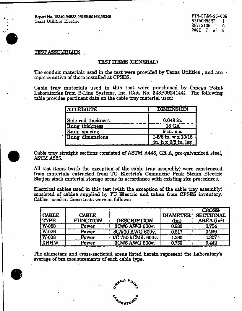
1%B1''PEAS (GENERAL)
The conduit materials used in the test were provided by Texas Utilities, and arerepresentative of those installed at CPSES.
Cable tray materials used in this test were purchased by Omega PointLaboratories from B-Line Systems, Inc. (Cat. No. 248P0924144). The followingtable provides pertinent data on the cable tray material used:
ATXRIBUTE
Side rail thicknessRun thicknessRun s acinRung dimensions
DMENSION
0.048 in.18 GA
9 in. o.c.1-5/8 in. w x 13/16in. h x 3/8 in. le
Cable tray straight sections consisted of ASTM A446, GR A, pre-galvanized steel,ASTM A525.
All test items (with the exception of the cable tray assembly) were constructedfrom materials extracted from TU Electric's Comanche Peak Steam electricStation stock material storage areas in accordance with existing site procedures.
Electrical cables used in this test (with the exception of the cable tray assembly)consisted of cables supplied by TU Electric and taken from CPSES inventory.Cables used in these tests were as follows:
W420
CABLEFUNCXXON
PowerPowerPowerPower
DESCKPIXON3C/¹6 AWG 60Qv.3C/¹10 A%G 60Qv.l/C 750 kCMil.600v.3C/¹6 A%'G 600v.
09800.617
0.750
CBOSS-8ECTIONALAREA(in )
0.75402991.307
'.442
The diameters and cross-sectional areas listed herein represent the Laboratory'saverage of ten measurements of each cable type.
~~A 0o0
osa~o+
Report No. 12340-94583,95165-95168/5246Texas Utilities Electric
PTN-BFJM-96-005ATTACHHENT IREVISION 0PAGE 8 of 15
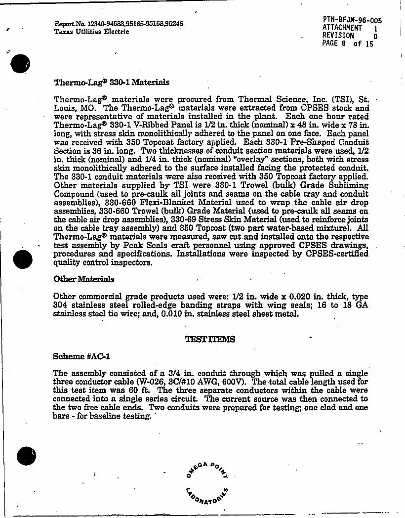
Thermo-Lag 330-1 Ma~tais
Thermo-Lag materials were procured from Thermal Science, Inc. (TSI), St.Louis, MO. The Thermo-Lag'aterials were extracted from CPSES stock andwere representative of materials installed in the plant. Each one hour ratedThermo-Lag 330-1 V-Ribbed Panel is 1/2 in. thick (normal) x 48 in. wide x 78 in.long, with stress skin monolith caQy adhered to the panel on one face. Each panelwas received with 350 Topcoat factory applied. Each 330-1 Pre-Shaped ConduitSection is 36 in. long. Two thicknesses of conduit section materials were used, V2in. thick (nominal) and 1/4 in. thick (nominal) "overlay" sections, both with stressskin monolithically adhered to the surface installed facing the protected conduit.The 330-1 conduit materials were also received with 350 Topcoat factory applied.Other materials supplied by TSI were 330-1 Trowel (bulk) Grade SublimingCompound (used to pre-caulk all joints 'and seams on the cable tray and conduitassemblies), 330-660 Flexi-Blanket Material used to wrap the cable air dropassemblies, 330-660 Trowel (bulk) Grade Material (used to pre-caulk all seams onthe cable air drop assemblies), 330-69 Stress Skin Material (used to reinforce jointson the cable tray assembly) and 350 Topcoat (two part water-based mixture). AllThermo-Lag materials were measured, saw cut and installed onto the respectivetest assembly by Peak Seals crude personnel using approved CPSES drawings,procedures and specifications. Installations were inspected by GPSES-ceitifiedquality control inspectors.
Other MateriaLs
Other commercial grade products used were: 1/2 in. wide x 0.020 in. thick, type304 stainless steel rolled-edge banding straps with wing seals; 16 to 18 GAstirless steel tie wire; and, 0.010 in. s'tainless steel sheet metal.
Scheme SAC-1
The assembly consisted of a 3/4 in. conduit through which was pulled a singlethree conductor cable (W-026, 3C/410 AWG, 600V). The total cab1e length used forthis test item was 60 ft. The three separate conductors within the cable wereconnected into a single series circuit. The current source was then connected tothe two free cable ends. Two conduits were prepared for testing, one clad and onebare - for baseline testing.

Report No. ~94583,95165-9516845246Texas Utilities Electric
PTN-BFJH-96-005ATTACHMENT 1
REVISION 0PAGE 9 of 15
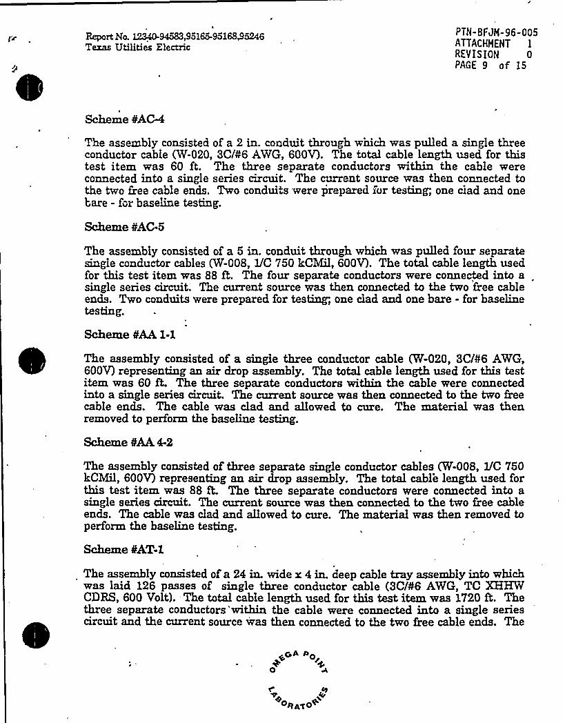
Scheme ¹AC4
The assembly consisted of a 2 in. conduit through wnich vras pulled a single threeconductor cable (W-020, 3C/¹6 AWG, 600V). The total cable length used for thistest item was 60 ft. The three separate conductors within the cable vrereconnected into a single series circuit. The current source was then connected tothe tvro free cable ends. Two conduits were prepared ror testing, one ciad and onebare - for base1iae testing.
Scheme ¹AC-5
The assembly consisted of a 5 in. conduit through vrhich was pulled four separatesingle conductor cables (W-008, 1/C 750 kCMil, 600V). The total cable leagth usedfor this test item was 88 ft. The four separate conductors were connected into asingle series circuit. The current source vras then connected to the two free cableends. Tvro coaduits were prepared for testing, one clad and one bare - for baselinetesting.
Scheme ¹AA1-1
The assembly consisted of a single three conductor cable (W-020, 3C/¹6 AWG,600V) representing an air drop assembly. The total cable length used for this testitem vras 60 ft. The three separate conductors within the cable were connectediato a single series circuit. The current source vras then connected to the two freecable ends. The cable was clad and allovred to cure. The material was thenremoved to perform the baseline testing.
The assembly consisted of three separate siagle conductor cables (W-008, 1/C 750kCMil, 600V) representing an air drop assembly. The total cable length used forthis test item was 88 ft. The three separate coaductors vrere connected into asingle series circuit. The current source was then connected to the tvro free cableeads. The cable vras clad aad allowed to cure. The material vras then removed toperform the baseline testing.
Scheme OAT-1
The assembly consisted of a 24 in. wide r 4 in. deep cable tray assembly into whichwas laid 126 passes of single three coaductor cable (3C/¹6 AWG, TC XHHWCDRS, 600 Volt). The total cable length used for this test item vras 1720 K Thethree separate conductors'withia the cable were connected into a single seriescircuit and the cuzrent source was then connected to the tvro free cable eads. The
~~A Do
0
rORA<O+
Report No. 12340-94583,95165-951685246Texas Utilities Electric
PTN-BFJH-96-005ATTACHHENT 1
REVISION 0PAGE 10 of 15
cable tray assembly vras clad and allowed to cure. The material was thenremoved to perform the baseline testing.
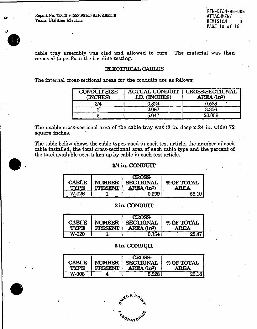
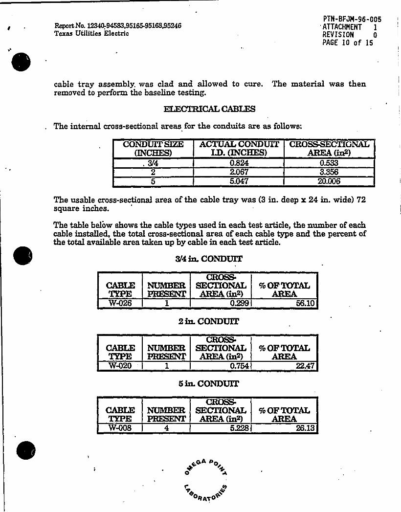
The internal cross-sectional areas for the conduits are as follows:
CONDUITSIZE(INCEST)
ACTUALCONDUITI33. (INCHES)
0.8242.0675.047
CROSSBE TIONALAIUM(in2)
0.5333.35620.006
The usable cross-sectional area of the cable tray was (3 in. deep r 24 in. wide) 72square inches.
The table below shows the cable types used in each test article, the number of eachcable installed, the total cross-sectional area of each cable type and the percent ofthe total available area taken up by cable in each test article.
3/4 in. CONDUIT
CABLETYPEW26
CEK)S&SECXXONALALUM (in2)
0299 I
2 in. CONDUIT
% OF TOTALAEU<M
56.10
W%20
CBOSS.SECTIONALABER (in2)
0.754
5 in. CONDUIT
% OF TOTALAIRE
22.47
CA'BL'E
W-008
CBXkS-NUMBER SECTXONALPBESENI,'BEA (in>)
5.228
% OF TOTALARE&
26.13
~GA DOr+
0
osA~o~
Report: No. 12340-94583,95165-95168/5246Texas Utilities Electric
PTN-BFJM-96-005ATTACHMENT 1
REVISION 0PAGE 11 of 15
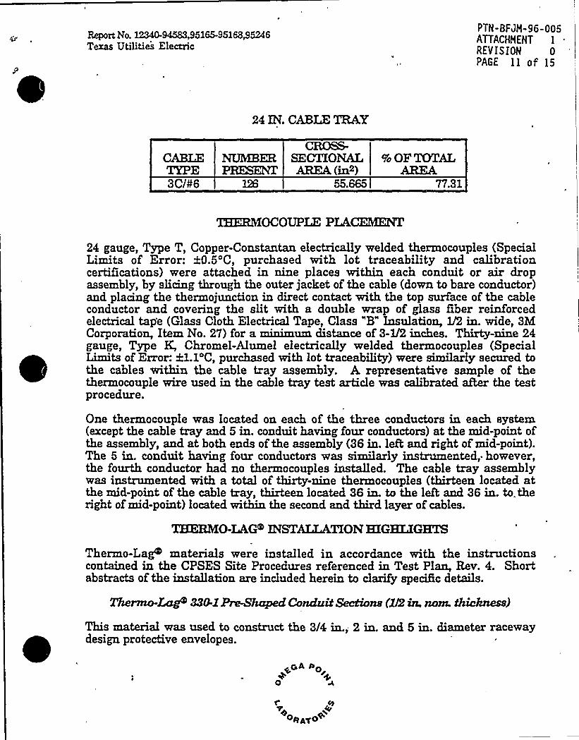
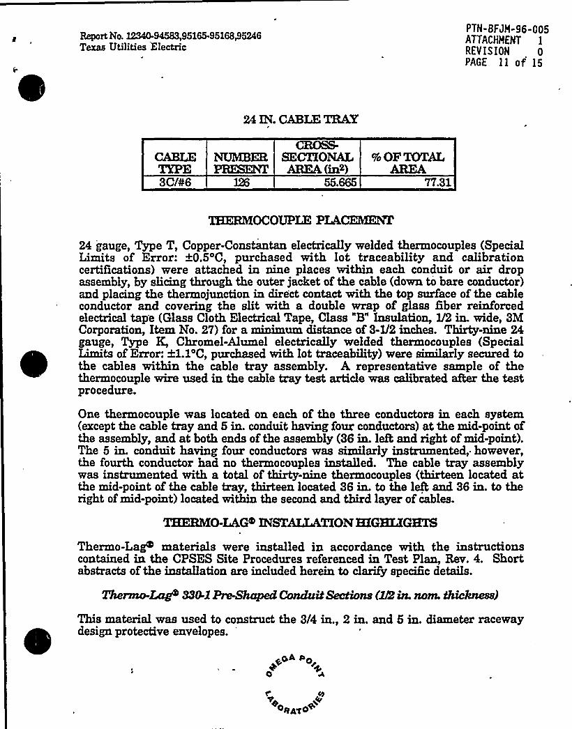
24 IN. CABLETRAY
3C/¹6
CROSS-SECTIONALAREA (in2)
9o OF TOTALAEU~M
77.31
TEEZUYCOCOUPLE PLACEZHKKT
24 gauge, Type T, Copper-Constantan electrically welded thermocouples (SpecialLimits of Error: 0.5'C, purchased with lot traceability and calibrationcertifications) were attached in nine places within each conduit or air dropassembly, by slicing through the outer jacket of the cable (down to bare conductor)and placing the thermojunction in direct contact with the top surface of the cableconductor and covering the slit with a double wrap of glass Qber reinforcedelectrical tap'e (Glass Cloth Electrical Tape, Class "B" Insulation, 1/2 in. wide, 3MCorporation, Item No. 27) for a minimum distance of 3-1/2 inches. Thirty-nine 24gauge, Type K, Chromel-Alumel electrically welded thermocouples (SpecialLimits of Error: 21.1'C, purchased with lot traceability) were siaMuly secured tothe cables within the cable tray assembly. A representative sample of thethermocouple wire used in the cable tray test article was calibrated aRer the testprocedure.
One thermocouple was located on each of the three conductors in each systexn(except the cable tray and 5 in. conduit having four conductors) at the mid-point ofthe assembly, and at both ends of the assembly (36 in. lefh and right of mid-point).The 5 in. conduit having four conductors was similarly instrumented,. however,the fourth conductor had no thermocouples installed. The cable tray assemblywas instrumented with a total of thirty-nine thermocouples (thirteen located atthe mid-point of the cable tray, thirteen located 36 in. to the left and 36 in. to, theright ofmid-point) located within the second and third layer of cables.
THERMhLAG INSTALLATIONHIGHLIGHTS
Thermo-Lag materials were installed in accordance with the instructionscontained in the CPSES Site Procedures referenced in Test Plan, Rev. 4. Shortabstracts of the installation are included herein to clarify specific details.
Thermo-Lag 330-X Pre-Shaped ConduM Sections (Xf2in. nom. thicknear)
This material was used to construct the 3/4 in., 2 in. and 5 in. diameter racewaydesign protective envelopes.
oA +00

0
Report No. 12340-94583,95165-95168+5246Texas Utilities Electric
PTN-BFJM-96-005ATTACHHEN7 1
REY IS ION 0PAGE 12 of 15
Thermo-Lag+ 330-1 Pre-Shaped Conduit Sections (I/4 in. nom. thickness)
This material was used as an overlay on the 3/4 in. and 2 in. diameter racewaydesign protective envelopes.
Thermo-Lag+ 330-1 U-ribbed Panels (I)2 in, nom. thickness)
This material was used to construct the cable tray protective envelope.
Thermo-Leg/'30-1 Subliming Trowel Grade Material
This material was used to pre-caulk all joints, seams and upgraded areasbetween pre-shaped sections.
Thermo-L,ag 33&660E7exi-BLm~
This material was used to construct the cable air drop protective envelopes.
Thermo-Lag 33~ Sublimb~'.Pnuael Grade Material
This material was used to pre-caulk all joints and seams between 330-660 Flexi-Blanket material and all joints of330-66- Flexi-Blanket.
Application Methods
Each rigid conduit assembly was clad with Thermo-Lag 330-1 V2 in. (nominal)thick Pre-Shaped Conduit Section Material. All joints and seams were pre-caulked with 330-1 Trowel Grade Material. The sections installed on the 5 in.diameter conduit were secured using stainless steel banding material. Thesections installed on the 3/4 in. and the 2 in. diameter conduits were securedusing stainless steel tie wire. ARer being clad with 1/2 in. thick 330-1 Pre-ShapedConduit Sections, V4 in. thick (nominal) Pre-Shaped Conduit Section ("overlay" )Material was installed on the 3/4 in. and the 2 in. diameter conduits. Alljointsand seams were pre-cauiked with 330-1 Trowel Grade Material and then securedusing stainless steel banding. Finally, Thermo-Lag 350 Topcoat was appliedover areas where the 330-1 Trowel Grade Material had been applied following a 72hour (mixumum cure time).
The entire cable tray system was clad with Thermo-Lag 330-1 V2 in. (nominal)V-Ribbed Panel Material. To prevent sagging of the top panels, the cable tray waspre-banded using stainless steel banding. Al joints and seams of the protectiveenvelope were pre-caulked with 330-1 Trowel Grade Material and secured withstainless steel bands spaced at 12 in, intervals.
~GA Do
0
C
~eo~a~o+

Report No. 12340-94583,95165-95168,95246Texas Utilities Electric
PTN-BFJM-96-005ATTACHMENT 1
REVISION 0PAGE 13 of 15
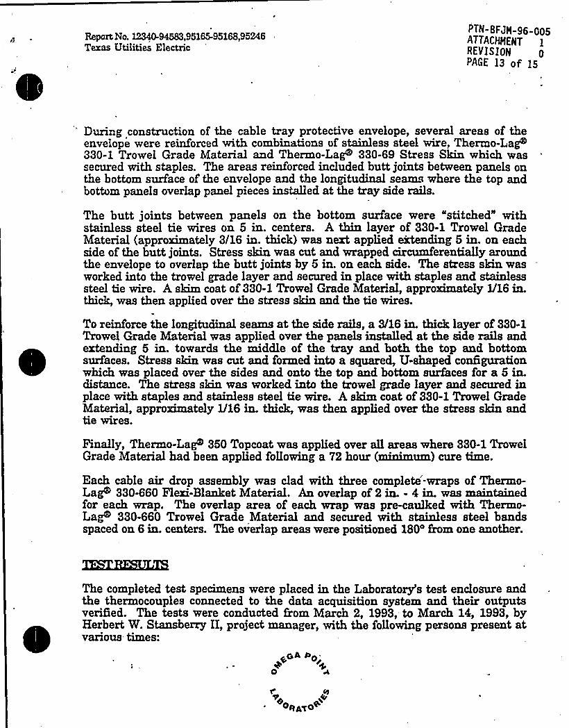
During construction of the cable tray protective envelope, several areas of theenvelope were reinforced vrith combinations of stainless steel wire, Thermo-LaP330-1 Trowel Grade Material and Thermo-Lago 330-69 Stress Skin vrhich wassecured with staples. The areas reinforced included butt joints betvreen panels onthe bottom surface of the envelope and the longitudinal seams where the top andbottom panels overlap panel pieces installed at the tray side rails.
The butt joints betvreen panels on the bottom surface were "stitched" withstainless steel tie wires on 5 in. centers. A thin layer of 330-1 Trowel GradeMaterial (approximately 3/16 in. thick) was aext applied extending 5 in. on eachside of the butt joiats. Stress skin was cut and wrapped circumferentially aroundthe envelope to overlap the butt joints by 5 ia. oa each side. The stress shin wasworked into the trowel grade layer and secured ia place with staples and stainlesssteel tie wire. A skim coat of 330-1 Trowel Grade Material, approximately V16 in.thick, was then applied over the stress skia and the tie vrires.
To reinforce the longitudinal seams at the side rails, a 3/16 in. thick layer of 330-1Trovrel Grade Material vras applied over the panels installed at the side rails andextending 5 ia. tovrards the middle of the tray and both the top and bottomsurfaces. Stress skin vras cut and formed into a squared, U-shaped configurationwhich vras placed over the sides and onto the top and bottom surfaces for a 5 in.distance. The stress skin vras worked into the trovrel grade layer and secured inplace with staples and stainless steel tie wire. A skim coat of 330-1 Trowel GradeMaterial, approximately V16 in. thick, was then applied over the stress skin andtie wires.
Finally, Thermo-Lag 350 Topcoat was applied over all areas where 330-1 TrowelGrade Material had been applied follovring a 72 hour (minimum) cure time.
Each cable air drop assembly was clad with three complete-wraps of Thermo-Lag 330-660 Flexi-Blanket Material. An overlap of 2 ia. - 4 in. was maintainedfor each wrap. The overlap area of each wrap was pre-caulked with Thermo-Lag 330-660 Trowel Grade Material and secured with stainless steel bandsspaced on 6 in. centers. The overlap areas vrere positioned 180'rom one another.
The completed test specimens were placed in the Laboratory's test enclosure andthe thermocouples connected to the data acquisition system and their outputsverified; The tests vrere conducted from March 2, 1993, to March 14, 1998, byHerbert W Stansberry II, project manager, with the follovring persons preseat atvarious times:
~oA Oo
0
r Cy
~ oeA~o~
0
Report No. ~~'4M3,961%-96168$ 6246Texas Utilities Electric
PTN- BFJH-96-005ATTACHHENT 1
REVISION 0
PAGE 14 of 15
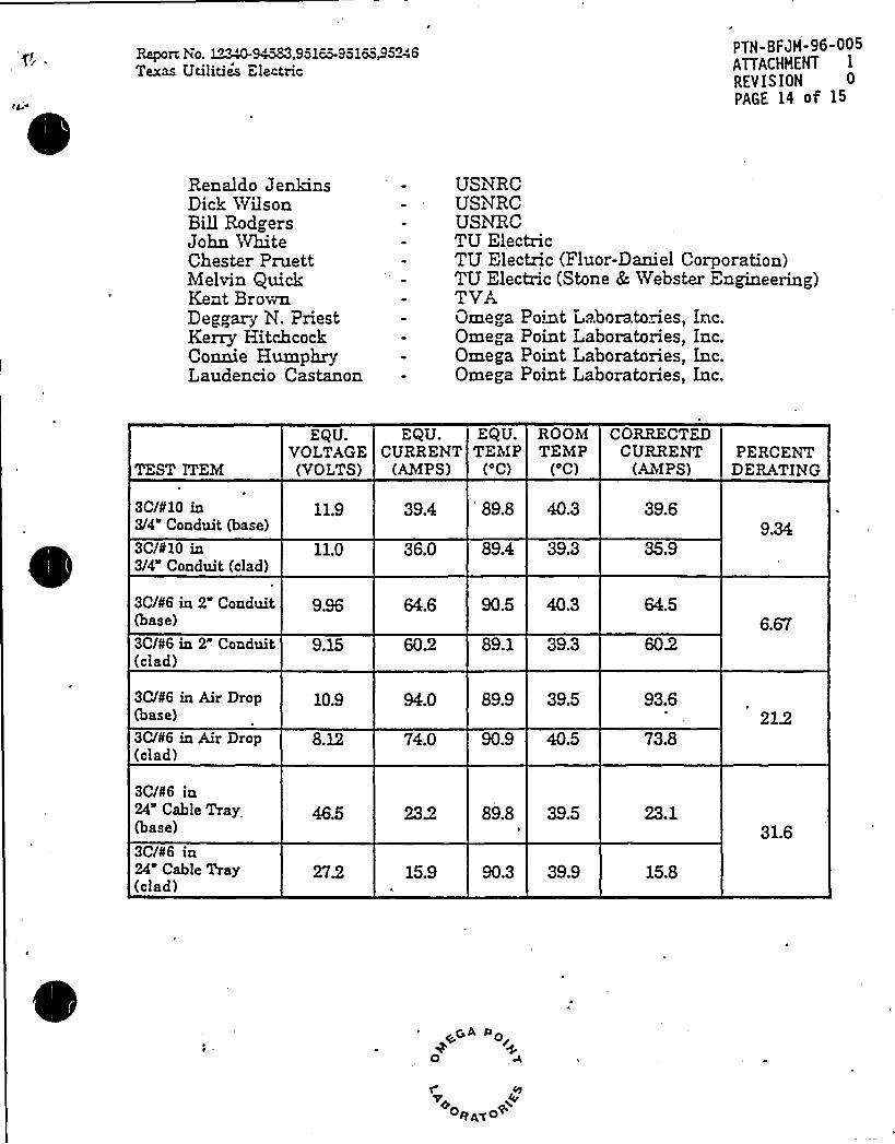
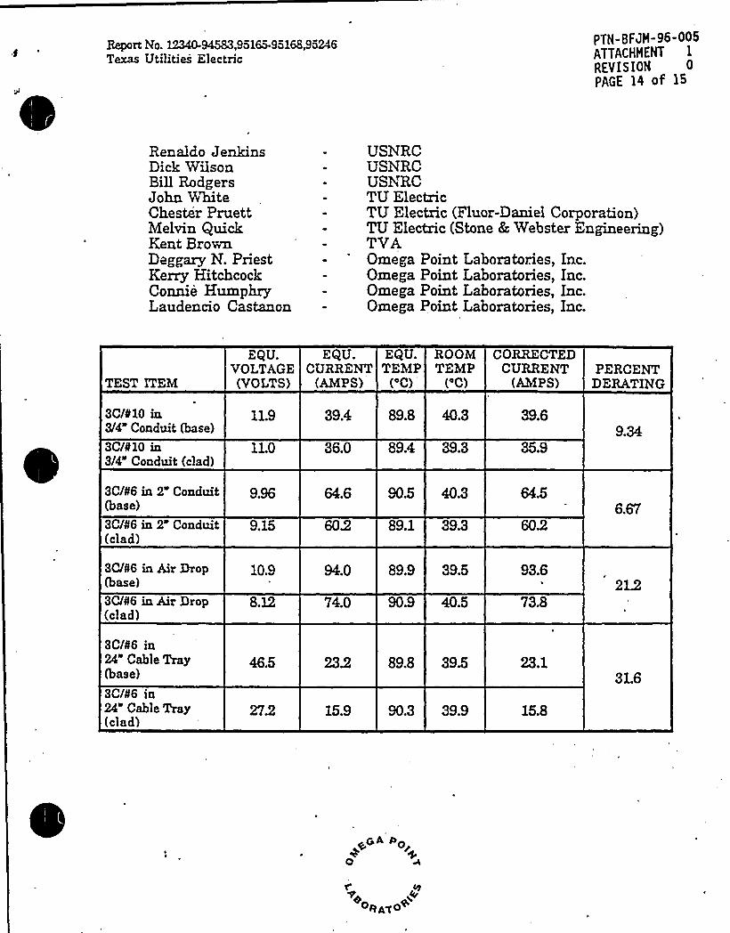
Renaldo JeansDick WilsonBillRodgersJohn WhiteChester PruettMelvin QuickKent BrownDeggarg N. PriestKerry HitchcockConnie HumphryLaudencio Castanon
USNRCUSNRCUSNRCTU ElectricTU Electric (Fluor-Daniel Corporation)TU Electric (Stone &, Webster Engineering)TVAOmega Point Laboratories, Inc.Omega Point I aboratories, Inc.Omega Point Laboratories, Inc.Omega Point Laboratories, Inc.
TEST ITEM
EQU.VOLTAGE(VOLTS)
EQU. EQU.CURRENT TEMP
(AMPS) ('C)
ROOM CORRECTEDTEMP CURRENT PERCENT
('C) (AMPS) DERATING
3C/¹10 in3/4" Conduit (base)
3C/¹10 in3/4 Conduit (clad)
11.9
11.0 36.0 89.4
39.4 89.8 40,3
39,3
39.6
35,99.34
3C/¹6 in 2" Conduit(base)
3C/¹6 in 2 Conduit(clad)
3C/¹6 in AirDrop(base)
3C/¹6 in AirDrop(clad)
3C/¹6 in24" Cable Tray(base)
3C/¹6 in24 Cable Tray(clad)
9.15
10.9
,
8.12
46.5
64.6
94.0
74.0
15.9
89.1
89.9
90.9
89.8
90.3
40.3
39.3
39.5
40.5
39.5
39.9
64.5
93.6
73.8
23.1
15.8
6.67
212
31.6
~oa Do
0
r Cy
oea~<~
Report No. 12340-94583,95165-95168g5246Texas Utilities Electric
PTN-BFJH-96-005ATTACHHENTREVISION 0PAGE 15 og 15
TEST ITEM
EQU.VOLTAGE(VOLTS)
EQU. EQU. ROOMCURRENT TEMP TEMP
(AM
PS�)
('C) ('C)
CORRECTEDCURRENT
(AMPS)PERCENT
DERATING
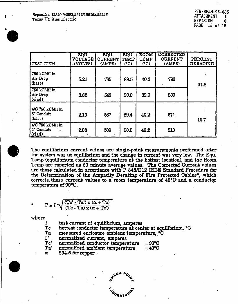
750 kCMil inAir Drop(ba" e)
750 kCMil inAir Drop(clad)
521
3.62
89.5 402
90.0 39.9
31.8
4C 750 kCMil in5 Conduit(base)
4/C 750 kCMilin5 Conduit(clad)
2.19
2.08
89.4 402
90.0 402 510
, 10.7
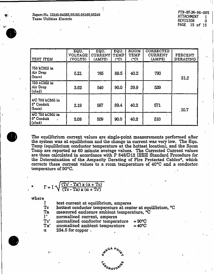
The equilibrium current values are single-point measurements performed afterthe system was at equilibrium and the change in current was very low. The Equ.Temp (equilibrium conductor temperature at the hottest location), and the RoomTemp are reported as 60 minute average values. The Corrected Current valuesare those calculated in accordance with P 848/D12 IEEE Standard Procedure forthe Determination of the Ampacity Derating of Fire Protected Cables~, whichcorrects these current values to a room temperature of 40'C and a conductor.temperature of 90'C.
whereITcTaI ~
Tc'a'Tc'-
Ta') x(a+ Tc)(Tc - Ta) x (u + Tc')
test current at equilibrium, ampereshottest conductor temperature at center at equilibrium, 'Cmeasured enclosure ambient temperature, 'Cnormalized current, amperesnormalized conductor temperature = 90'Cnormalized ambient temperature = 40'C234.5 for copper .
~~A Po
0
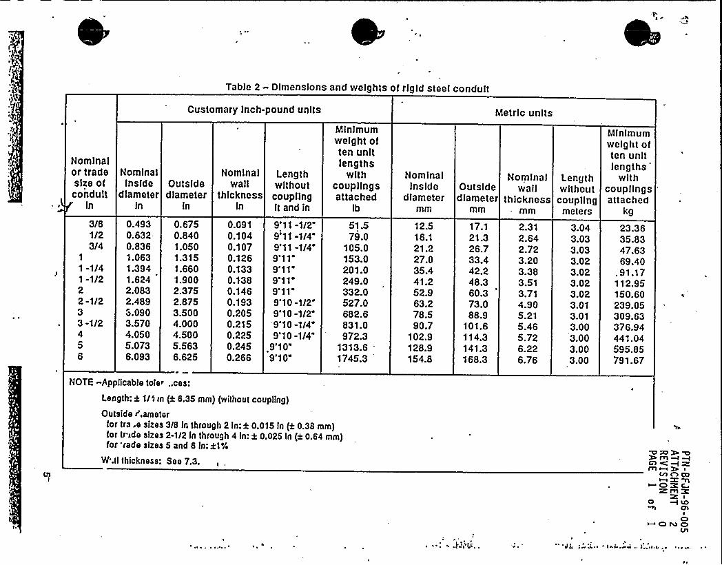
Table 2 - Dlmenslons and weights of rigid steel conduit
Customary inch-pound units Metric units
Nominalor tradesize ofconduit
In
Nominalinside Outside
diameter diameterln ln
Nominalwall
thicknessin
Lengthwithoutcouplingft and in
Minimumweight often unitlengths
withcoupllngsattached
Ib
NominalInside
diametermm
Outsidediameter
Nominal Lengthwall without
thickness couplingmm meters
Minimumweight often unitlengths
withcoupllngs
'ttached
kg3/81/23/4
1
1 -1/41 -1/222 -1/233 -1/2456
0.4930.632-0.8361.0631.3941.6242.0832.4893.0903.5704.0505.0736.093
0.6750.8401.0501.3151.6601.9002.3752.8753.5004.0004.5005.5636.625
0.0910.1040.1070.1260.1330.1380.1460.1930.2050.2150.2250.2450.266
9'11 -1/2"9'11 -1/4"9'11 -1/49'119'119'119'119'10 -1/29'10 -1/29'10 -1/49'10 -1/4
9'109'10"
51.579.0
105.0153.0201.0249.0332.0527.0682.6831.0972.3
1313.61745.3
12.516.121.227.035.441.252.963.278.590.7
102.9128.9154.8
17.121.326.733.442.248.360.373.088.9
101.6114.3141.3168.3
2.312.642.723.203.383.513.714.905.215.465.726.226.76
3.043.033.033.023.023.023.023.013.013.003.003.003.00
23.3635.8347.6369.40
. 91.17112.95150.60239.05309.63376.94441.04595.85791.67
NOTE -Applicable toie~ ..ces:
Length: k 1/0 in (k 8.35 mm) (without coupling)
Outside I',ameterfor tra.e sizes 3/8 in through 2 In: k 0.015 In (a 0.38 mm)for tr ide sizes 2-1/2 In through 4 ln: k 0.025 In (k 0.64 mm)for 'rade sizes 5 and 6 In:21%
N'.ll thickness: See 7.3. mC) <m~
C/l
I
AmllI
W lClOII
C)N OCll
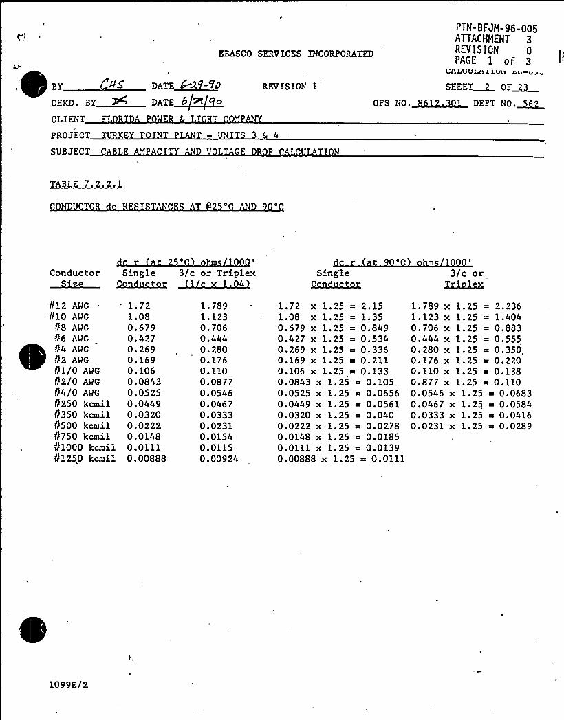
EBASCO SERVICES INCORPORATED
PTN-BFJH-96-005ATTACHHENT 3REVISION 0PAGE I of 3
~P
By 45CHKD. BY
CLIENT
PROJECT
SUBJECT
DATE 4 2V-VO
DATE
REVISION 1
UAIuVMI iVii
SHEET~ OF~OFS NO.~ DEPT NO.~
4
Conductor Single 3/c or Triplex Sing'leCasubu;hu;
3/c orXrh>JJs
812 AWG
810 AWG
88 AWG
N6 AWG
P4 AWG
N2 AWG
N1/0 AWG
02/0 AWG
04/0 AWG
8250 kcmil8350 kcmil8500 kcmil8750 kcmil81000 kcmll81250 kcmil
1.721.080.6790.4270.2690.1690.1060.08430.05250.04490.03200.02220.01480.01110.00888
1.7891.1230.7060.4440.2800.1760.1100.08770.05460.04670.03330.02310.01540.01150.00924
1.72 x 1.25 = 2.151.08 x 1.25 = 1.350.679 x 1.25 = 0.8490.427 x 1.25 = 0.5340.269 x 1.25 ~ 0.3360.169 x 1.25 = 0.2110.106 x 1.25 = 0.1330.0843 x 1.25 = 0.1050.0525 x 1.25. = 0.06560.0449 x 1.25 = 0.05610.0320 x 1.25 = 0.0400.0222 x 1.25 = 0.02780.0148 x 1.25 = 0.01850.0111 x 1.25 = 0.01390.00888 x 1.25 = 0.0111
= 2.2361.404
= 0.883= 0.555= 0.350.= 0.220= 0.138= 0.110
= 0.0683= 0.0584= 0.0416= 0.0289
1. 789 x 1. 251. 123 x l. 250. 706 x 1. 250.444 x 1.250. 280 x 1. 250.176 x 1.250.110 x 1.250.877 x 1.250.0546 x 1.250.0467 x 1.250.0333 x 1.250.0231 x 1.25
1099E/2
/"" ~d/CHKD. BX
CLIENT
PROJECT
SUBJECT
EBASCO SERVICES INCORPORATED
DATE > 2f Fo-
DATE~6Kq I>REVISION 1
PTN-BFJH-96-005)g
ATTACHHENT 3REVISION 0PAGE 2 of 3
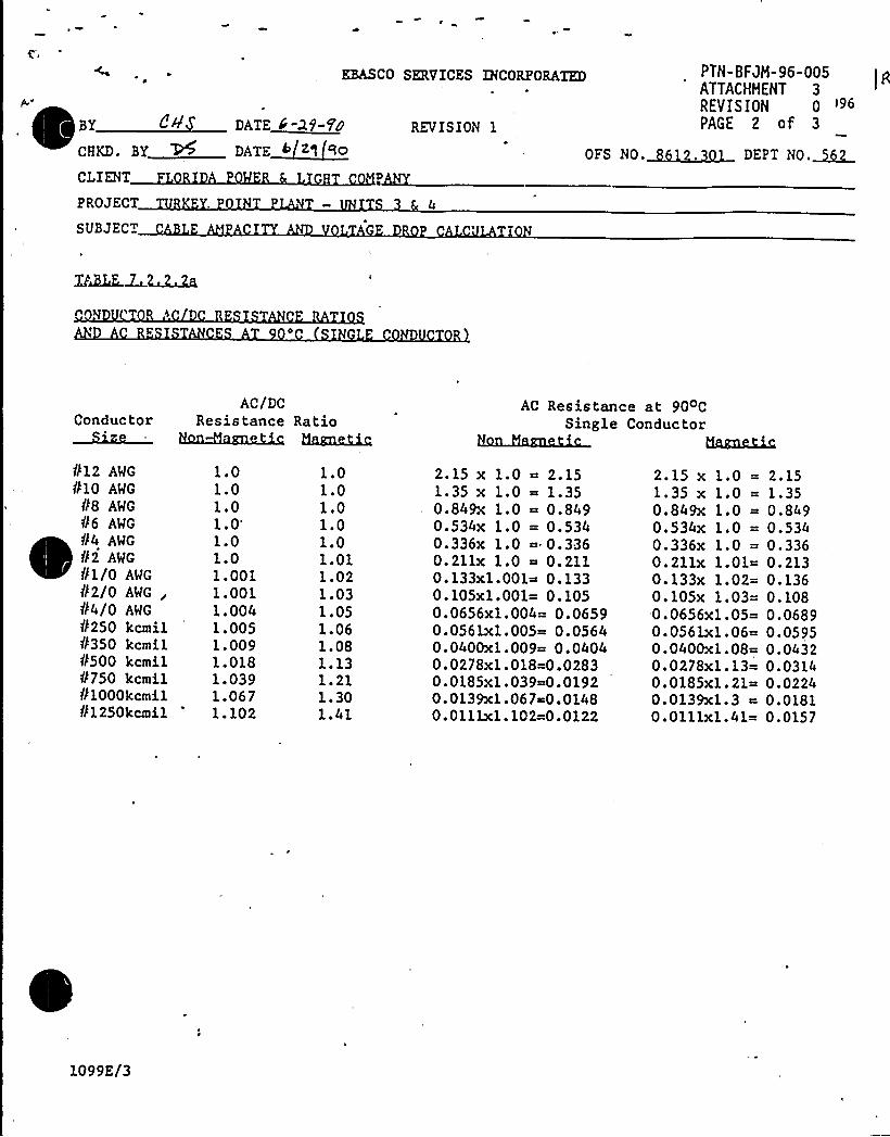
OFS NO.Q~~ DE P T NO.~
ConductorAC/DC
Resistance RatioAC Resistance at 90 C
Single ConductorHakim~
N12 AWG
Nlo AWG
N8 AWG
N6 AWG
N4 AWG
N2 AWG
Nl/0 AWG
N2lo AWG
NOIO AWG
N250 kcmilN350 kcmil'N500 kcmilN750 kcmilN1000kcmi1N1250kcmi1
1.01.01.01.
0'.0
1.01.0011.0011.0041.0051.0091.0181.0391.0671.102
1.01.01.01.01.01.011.021.031.051.061.081 ~ 131.211.301.41
2.15 x 1.0 = 2.151.35 x 1.0 = 1.350.849x 1.0 ~ 0.8490.534x 1.0 = 0.5340.336x 1.0 = 0.3360.2llx 1.0 ~ 0.2110.133x1.001~ 0.1330.105x1.001= 0.1050.0656x1.004= 0.06590.056lx1.005= 0.05640.0400xl.009= 0.04040.0278xl.018=0.02830.0185x1.039=0.01920.0139x1.067~0.01480.0111x1.102=0.0122
2.15 x 1.0 =1.35 x 1.0 =0.849x 1.0 =0.534x 1.0 =0.336x 1.0 =0.211x 1.01=0.133x 1.02=0.105x 1.03=0.0656x1.05=0.0561xl.06=0.0400xl.08=0.0278x1.13=0.0185x1.21=0.0139x1.3 ~0.011lx1.41=
2.151.350.8490.5340.3360.2130.1360.1080.06890.05950.04320.03140.02240.01810.0157
1099E/3
.CHKD. BY
CLIENT
PROJECT
SUBJECT
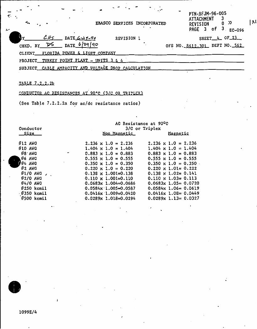
PTN-,BFJM-96-005ATTACHMENT 3
RfVISION 0
PAGE 3 of EC-096
EBAS«SERVICES INCORPORATED
DATE~M-WuDATE~62/ qO
REVISION 1 S8FET 4 OF~OFS NO.Q~~ DEPT No.~
0
(See Table 7.2.2.2a for ac/dc resistance ratios)
ConductorAC Resistance at 90 C
3/C or TriplexUazm~
812 AWG
010 AWG88'WG86 AWG
t4 AWG
82 AWG
81/0 AWG
82/0 AWG
84/0 AWG
8250 kcmil8350 kcmil8500 kcmil
2.236 x1.404 x0.883 x0.555 x0.350 x0.220 x0.138 x0.110 x0.0683x0.0584x0.0416x0.0289x
1.0 = 2.2361.0 = 1.4041.0 = 0.8831.0 = 0.5551.0 = 0.3501.0 = 0.2201.OOl=O.1381.001=0.1101.004=0.06861.005~0.05871.009=0.04201.018=0.0294
2.236 x1.404 x0.883 x0.555 x0.350 x0.220 x0.138 x0.11'0 x0.0683x0.0584x0.0416x0.0289x
1.0 =1.0 =1.0 =1.0 =1.0 =1.01=1.02=1.03=1.05=1.06=1.08=1.13=
2.2361.4040.8830.5550.350-0.2220.1410.1130.07200.06190.04490.0327
1099E/4
1N C.
APPROVED FIRE BARRIERS FORTHE biUCLEAR INDUSTRY
therma-hg'30-1 F IRE BARRIER
MATERIAl.PROPERTIES
PTN-BFJH-96-005ATTACHHENT 4
REVISION 0PAGE I of 2
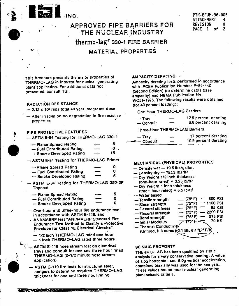
This brochure presents the major properties ofTHFRMO-LAG in interest for nuclear generatingplant application. For additional data not
'resented.consult TSI.
RADIATIONRESISTANCE—2.12 x 1P rads total 40 year integrated dose
—After irradiation no degradation in fire resistiveproperties
FIRE PROTECTIVE FEATURES—ASTM E-84 Testing for THERMO-LAG 330-1
—Flame Spread Rating 5—Fuel Contributed Rating — 0 ..- Smoke Developed Rating — 15
—ASTM E-84 Testing for THERMO-LAG Primer
—Flame Spread Rating 0—Fuel Contributed Rating — 0—Smoke Developed Rating — 5
—ASTM E-84 Testing for. THERMO-LAG 350-2PTopcoat—Flame Spread Rating 5—Fuel Contributed Rating — 0—Smoke Developed Rating — 0
—One-hour and .htee-hour fire endurance testin accordance with ASTM E-119, and
. ANI/MAERPtest "ANI/MAERPStandard FireEndurance Test Method to Qualify a ProtectiveEnvelope for Class 1E Electrical Circuits".
—1/2 Inch THERMO-LAG rated one hour—1 Inch THERMO-LAG rated three hours
~ . —, ASTM E-119 hose stream test on electricaltrays and conduit for one and three hour ratedTHERMO-LAG (2-1/2 minute hose stream
~~
application)—ASTM E-119 fire tests for structural steel,
hangers to determine required THERMO-LAGthickness for one and three nour rating
AMPACITYDERATING
Ampacity derating tests performed in accordancewith IPCEA Publication Number P-54-440(Second Edition) (to determine cable base
ampacity) and NEMA Publication No.WC51-1975. The following results were obtained(for 40 percent loading):
One-Hour THERMO-LAG Barriers
—Tray — 12.5 percent derating—Conduit 6.8 percent derating
Three-Hour THERMO-LAG Barriers
—Tray 17 percent derating~——Conduit — 10.9 percent derating
MECHANICAL(PHYSICAL) PROPORTIES—Density wet —10.5 Ibs/gallon—Density dry —75~3 Ibs/tP—Dry Weight 1/2 inch thickness
(one-hour rated) ~ 3.25 Ib/ftz—Dry Weight 1 inch thickness
(three-hour rated) = 6.5 Ib/fthm
—Water based—Tensile strength p5'F) — 800 PSI
—Shear strength —p5'F) —1100 PSI
—Flexural stitfness —(75'F) 85 KSI—Flexural strength —p5') —2200 PSI
—Bond strength —p5') —575 PSI—initial Modulus ~>~'F) — 70 KSI—Thermal Conductivity
(Unfired, full cured) 0.1 Btu/hr tt.~ F/
SEISMIC PROPORTYTHERMO-LAG has been qualified by staticanalysis for a very conservative loading. A value
of 7.5g horizontal, and 6.0g vertical acceleration.combined biaxially was used for the analysis.These values bound most nuclear generatingplant seismic criteria.
~ 'torage Conaitionst'bove 32'F and below100'F'sbestoesfree
Non-toxic
—High humidi;y—Industrial atrnospnere (COr —SO> mix)—Salt spray
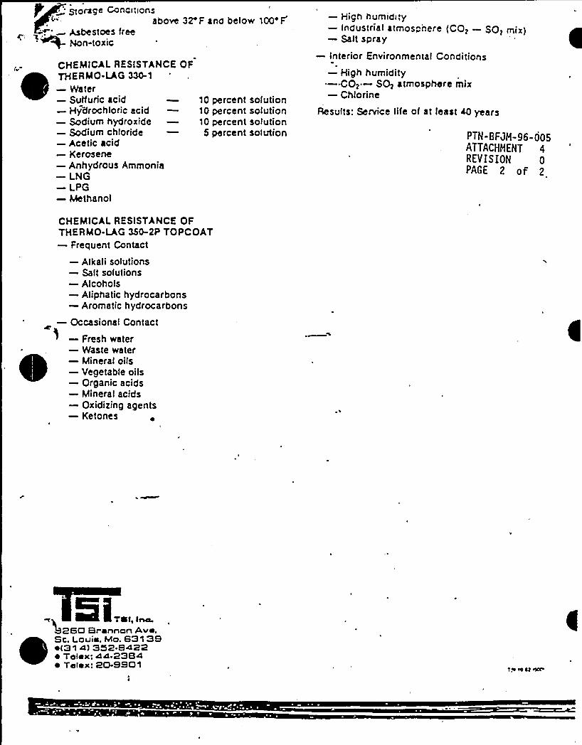
C HEMICAL RESISTANCE OFTHERMO-LAG 330-1—Water—Sulfuric acid—Hydrochloric acid—Sodium hydroxide—Sodium chloride—Acetic acid—Kerosene—Anhydrous Ammonia—LNG—LPG—Methanol
101010
5
percent solutionpercent solutionpercent solutionpercent solution
—Interior Environmental Conditions—High humidity—COz —SO> atmosphere mix—Chlorine
Results: Service life of at least 40 years
PTN-BFJM-96-005ATTACHMENT 4REVISION 0PAGE 2 of 2
CHEMICALRESISTANCE OFTHERMO-LAG 350-2P TOPCOAT—Frequent Contact
—Alkali solutions—Salt solutions—Alcohols—Aliphatic hydrocarbons—Aromatic hydrocarbons
—Occasional Contact—Fresh water—Waste water—Mineral oils—Vegetable oils—Organic acids—Mineral acid s—Oxidizing agents—Ketones
. Si...,,260 Br snnon Ave
Sc. Louis, Mo. 631 39~ t31 4) 352 8422s Telex: 44 2384~ Telex: 20-9901
PTN-BFJH-96-005ATTACHHENT 1
REVISION 0
PAGE 1 of 15
AMPACITY DEBATING OFFIRE PROTECT'ED CABLES
Pmject No. 12340-94583,95165-95168/5246
ELECTRICALTEST TO DETERMINE THE AMPACITYDERATINGOF APROTECTIVE ENVELOPE FOR CLASS 1E ELECTRICAL
CIRCUITS
March 19, 1993
Prepared For.
TU ElectricCOAGQlCHE PEAK STEAM ELECTRIC STATION
P.O. Box 1002Glen Rose, Texas 76043-1002
~gA ~o0 *
E..'REGE)YED DGT 2 0 )s93
oeATOO
Repo*Nc 12340-94583,95165-95168/5246Texas Utilities"Electric
PTN-BFJH-96-005ATTACHNEMT IREV IS IOH 0PAGE 2 of 15
Three conduit assemblies, two air drop assemblies, and one cable tray asseinbly,clad with Thermo-Lag materials as described herein, were evaluated inaccordance with the Texas UtilitiesElectric TEST PLAN, Rev. 4, yielding thefollowing ampacity derating values:
TEST ITEMPERCENT
DERATING
3C/¹10 in 3/4" Conduit3C/¹6 in 2" Conduit3C/¹6 in AirDro24" Cable Tra750 kCMilin AirDro4/C 750 kCMilin 5" Conduit)
9,346.6?
3L631.810.7
The details, procedures and observations reported herein are correct and truewithin the hmits of sound engineering practice. All specimens and test sampleassemblies were produced, installed and tested under the surveillance of eitherTexas Utilities'r the testing laboratory's Quality Assurance Program. Thisreport describes the ana1ysis of distinct assemb1ies and includes descriptions ofthe test procedure followed, the assemblies tested, and all results obtained. Alltest data are on BIe and remain available for review by authorized persons.
Herbert W. Stansberxy IIProject Manager
Date
Constance A. HumphreyManager, QA Dept.
Deggary ¹ PriestPresident
Date
~>4 "o0
oea~o+

0
0
0
Report No. ~94583,95165-95168@&?A6Texas Utilities Electric
PTN-BFJN-96-005ATTACHMENTREVISIONPAGE 3 o~ I~
TABLEOF CONTENTS
INTRODUCTION'HMTPROCEDURE
Test Enclosure
Thermo couplesData Acquisition system
Current Control System: Final Current Measurements
TEST ASSEMBLYTest Items (General)
Test ItemsElectrical Cables
Thermocouple PlacementThermo-Lag Installation Highlights
'H<DTRESULTS
APPENDICES
Appendix A: CONSTRUCTION DRAWINGS
Appendix B: TEST PLANAppendix C: THERMOCOUPLE LOCATIONS
Appendix D: TABULARTEST DATAAppendix E: QUALITYASSUEVLÃCE
Appendix F: PHOTOGRAPHS
Appendix G: THERMO-LAG INSTALLATIONLast Page ofDocument
1
1
1
2
2
2
3
4
4
5
7
8
8
1D
i338
25
32
382
781
DETAILS 802
8%
~A OO
0
4y~e
eAt<

Report No. 12340-94583,95165-95168/5246Texas Utilities Electric
PT¹-8FJH-96-005ATTACHHENT 1
REV IS IO¹ 0PAGE 4 of 15
A Fire Protective Envelope protects electrical components from the eG'ects of fire.In doing so, it willreduce the inQow of energy into the system and maintain theinternal temperature below maximum limits. These limits will ensure that thecable systems remain functional during a fire, and allow operators to maintaincontrol of systems required for fire safe shutdown..
The addition of a Fire Protective Envelope on a cable system willnot only protectthe contained cable from elevated temperatures associated with a fire, but willimpede the heat dissipation associated with cable operation. The evaluationdescribed herein will yield an accurate and realistic value for the ampacityderating of cables when a Fire Protective Envelope is'instaQed on the cable system.
This entire test program was performed in accordance with Texas UtilitiesElectric TEST PLAN, Rev. 4, which has been included in Appendix B. Thespecific details of this project willbe found in that document.
The ampacity test enclosure was constructed of steel stud walls and ceiling with amuiimum of 1 in. of polystyrene insulation lining the interior of the room. TheoveraQ dimensions of the test enclosure were 20 ft. x 18 R. x 8 R. An entry doorwas provided in one wall and an observation window was placed in an adjacentwaQ. The waQ with the observation window was made to be removable to facilitateeasier location of test articles. Four 1.5 RW heaters were disposed about the roomto regulate ambient conditions. Two of the heaters were variable from outside ofthe test enclosure via connection to standard laboratory variable transformers.Located directly behind each heater was a 24 in. box fan to gently stir the air andmore evenly distribute the heat. A total of nine thermocouples were suspendedfrom the ceiling and positioned in the horizontal plane of the test items, 12 in.away from various test items to monitor the ambient room temperatures. Twostanchions were erected to support the test articles. Each stanchion consisted of alength of 2 in. square steel tubing supported at several points by an A-frame leg.A length of 2 in. x 4 in. wood stud was afBxed to,the top surface of each stanchion.
In the case of all but the 5 in. conduit, the test article with the fire protectivesystem installed was tested first. Once the system had attained equilibrium andall final measurements had been taken, the fire protective barrier was removedfrom the system (in the case of the air drop assemblies and the cable tray
~oA Aor+
0 ~4
Cg
o~a~o+
Report No. 12340-94583,95165-95168@5246Texas Utilities Electric
PTN-BFJH-96-005ATTACHMENT IREVISION 0PAGE 5 of 15
assembly) or the instrumented cable was removed from the clad conduit andinserted into a similarly constructed, bare conduit.
TEGWKOCOUPUH
Temperatures on the cable conductors within the conduit and air drop assemblieswere measured with Type T, 24 gauge, Copper-Constantan electrically weldedthermocouples formed from Copper and Constantan wires of "special limits oferror (M.5'C)," and covered with TeQon FEY insulation. Temperatures on thecable conductors within the cable tray assembly were measured with Type K, 24ga'uge, Chromel-Alumel electrically welded thermocouples formed fromChromel and Alumel wires of "special limits of error (%1.1'C)," and covered withbraided fiberglass insulation. All thermocouple wire was calibrated to &.5 C.
DATAACQUISXHONSYSTEM
The outputs-of the test article thermocouples and room control thermocoupleswere monitored by a data acquisition system consisting of a John Fluke Mfg. Co.Model HELIOS I 2289A Computer Front End, and an Apple Computer Co.Macintosh Classic microcomputer. The Computer Front End was connected tothe RS422 Serial Interface Port of the Macintosh. The computer was programmedin MicrosoR BASIC to command the HELIOS unit to sample the data input lines,receive and convert data into a digital format, and to manipulate the data fordisplay on screen, the hard copy printout, and saving to hard disk. The computerprogram determined, and displayed, the average temperatures at each of thethree positions on each test article. The rate of change of temperature for theaverage of the thexmocouples located in the center portion of the test article wasthen calculated. All individual data points and calculated values were saved onhard disk at one minute intervals. A record of individual location temperatures,zmuamum temperatures and rates of change of temperatures was printed at Gveminute intervals. Alltest data is presented in Appendix F: TEST DATA.
CORZROL SYBZESX
The current Qow through the test articles was regulated using process controltype devices. The available voltage for any test control circuit was 208 Vac singlephase. A Silicon Controlled=Rectifier (SCR) device (Ha1mar Robicon Group ModelNo. 140P-FK2-CL) was used to vary the voltage available to the primary side of astep-down transformer between 0 Vac and 208 Vac in proportion to a 4-20 mAcontrol input. The test article was connected to the secondary side of the step-down transformer. A proportional-integral-derivative process controller(Honeywell Universal Digital ControQer Model No. UDC 3002-0-000-1-00-ZQZ)was responsible for generating the 4-20 mA signal fed to the SCR device, based ona voltage feedback loop. A current transformer (Flex-Core Model No. 58-151, 150:5
~~A Agr+
0 *07
OATO

Report No. 12340-94583,95165-95168/5246Texas Utilities Electric
PTN-BFJH-96-005ATTACHHENT IRE VIS ION 0PAGE 6 of 15
or 76-102, 1000:5 ratio; input amps:output amps) was fitted to one lead of the testarticle to monitor the current flow'hrough the conductor. The output of thecurrent transformer was connected to a current transducer (Flex-Core Model No.CT5-005A) with a mA to mV converter (Flex-Core Model No. LRB-10000) toproduce a 0-10 Vdc signal proportional to a 0-150 A or 0-1000 A current span in thesample conductor. This 0-10 Vdc signal is used as the "process variable" in thefeedback loop to the controller. 'In essence, the above circuitry made up aconstant-curx'ent device, insensitive to line voltage changes.
The current in any given system was driven to a level high enough to bring theconductor to 90'G as quickly as possible by increasing the'output signal of theprocess controller via keypad commands. As the conductor temperatureapproached 90'C, the current level was reduced and the test article was giventime to respond to current changes before another adjustment was made to the
'urrent.During this time period, the controller was turned to "automatic" controland the "process variable set point" (the voltage output from the currenttransformer that represents the current level at which the controller willmaintain the system) was adjusted to the same value as the displayed processvariable (the controller varies its output in order the maintain the process variableat the level indicated by the set point).
This process of adjusting the controller output (and the control variable set point)and waiting for the system to stabilize (about 1/2 hour to about 2 hours, dependingupon the nature of the system) was continued until the temperature parametersof the test article were within the specified limits. The controller was allowed tooperate the system for a minimum of three hours. If, at the end of three hours,the system was still within the bounds of all specifications, a final current andvoltage measurement were taken and the system was deemed .to be inequilibrium.
All final current measurements were performed using ammeters supplied andcalibrated by Texas Utilities Electric. These ammeter used were manufactured byJames Biddle Co. and identified as Biddle Instruments Digital Clamp-On RMSVolt-Aauneter, Cat. No. 278001 (TU Electric ID No. IC-1029 and IC-1030).Measurements recorded for test items containing 3C/¹10 AWG of 3C/¹6 AWGcable were taken with the ammeter ID No. IC-1030. Current measurementsrecorded for test items containing 750 kCMil cable were taken with the ammeterID No. IC-1029. Calibration documentation for these devices can be found inAppendix G: Quality Assurance.
Ops 0+
Repo*Na 12340-94583,95165-95168/5246Texas Utilities Electric
PTN-BFJH-96-006ATTACHHENT IREVISION 0PAGE 7 of 15
xeEZ IXZ2tB(GENEtIALl
The conduit materials used in the test were provided by Texas Utilities, and arerepresentative of those installed, at CPSES.
Cable tray materials used in this test were purchased by Omega 'PointLaboratories from B-Line Systems, Inc. (Cat. No. 248P0924144). The followingtable provides pertinent data on the cable tray material used:
DIMENSION
Side rail thicknessRun thicknessRun s acinRung dimensions
0.048 in.18 GA
9 in. o.c.1-5/8 in. w x 13/16in. hx 3/8 in. le
Cable tray straight sections consisted ofASTM A446, GR A, pre-galvanized steel,ASTM A525.
AH test items (with the exception of the cable tray assembly) were constructedfrom materials extracted from TU Electric's Comanche Peak Steam ElectricStation stock material storage areas in accordance with existing site procedures.
Electrical cables used in this test (with the exception of the cable tray assembly)consisted of cables supplied by TU Electric and taken from CPSES inventory.Cables used, in these tests were as follows:
CAIKZTYPE%420W426W408
CABLEFUNCTION
PowerPowerPowerPower
DESCMPZIDN3C/¹6 AWG 600v.3C/¹10 AWG 600v.l/C 750 kCMil.600v.3C/¹6 AWG 600v.
0.617
0.750
CK538S.SECTIONALAREA(in?)
02991307
'.442
The diameters and cross-sectional areas listed herein represent the Laboratory'saverage of ten measurements of each cable type.
Report NL 12340-94583,95165-95168/5246Texas Utilities Electric
PTN-BFJH-96-005ATTACHHENT IREVISION 0PAGE 8 of 15
Thermo-Lag 330-1 Matexials
Thermo-Lag materials were procured from Thermal Science, Inc. (TSI), St.Louis, MO. The Thermo-Lag materials were extracted from CPSES stock andwere representative of materials installed in the plant. Each one hour ratedThermo-Lag 330-1 7-Ribbed Panel is 1/2 in. thick (nominal) x 48 in. wide x 78 in.long, with stress skin moaolithim~Jy adhered to the pand on one face. Hach panelwas received with 350 Topcoat factory applied. Each 330-1 Pre-Shaped ConduitSection is 36 in. long. Two thicknesses of conduit section materials were used, V2in. thick (nomixml) and 1/4 in. thick (nominal) overlay" sections, both with stressskin monolithically adhered to the surface installed facing the protected conduit.The 330-1 conduit materials were also received with 350 Topcoat factory applied.Other materials supplied by TSI were 330-1 Trowel (bulk) Grade SublimingCompound (used to pre-caulk all joints and seams on the cable tray and conduitassemblies), 330-660 Flexi-Blanket Material used to wrap the cable air dropassemblies, 330-660 Trowel (bulk) Grade Material (used to pre~ulk all seams onthe cable air drop assemblies), 330-69 Stress Skin Material (used to reinforce jointson the cable tray assembly) and 350 Topcoat (two part water-based mixture). AllThermo-Lag materials were measured, saw cut.and installed onto the respectivetest assembly by Peak Seals craS personnel using approved CPSES drawings,procedures and speci6cations. InstaQations were inspected by CPSES-certiGedquality control inspectors,
Other Materials
Other commercial grade products used were: V2 in. vride x 0.020 in. thick, type304 stainless steel rolled-edge banding straps with wing seals; 16 to 18 GAstainless steel tie wire; and, 0.010 in. stainless steel sheet metal.
Scheme ¹AC-I
The assembly consisted of a 3/4 in. conduit through which was pulled a singlethree conductor cable (W-026, 3C/¹10 AWG, 600V). The total cable length used forthis test item was 60 ft. The three separate conductors within the cable wereconnected into a single series circuit. The current source was then connected tothe two free cable ends. Two conduits were prepared for testing, one clad and onebare - for baseline testing.
~pa 04~L
4lrar4+
Report No. 12340-94583,95165-9516845246Texas Utilities Electric
PTN-BFJM-96-PP5ATTACHHENTREVISION 0PAGE 9 of I5
Scheme ¹AC4
The assembly consisted of a 2 in. conduit through which was pulled a single threeconductor cable (W-020, 3C/¹6 AWG, 600V}. The total cable length used for thistest item was 60 ft. The three separate conductors within the cable wereconnected into a single series circuit. The current source was then connected tothe two free cable ends. Two conduits were prepared for testing, one clad and onebare - for baseline testing.
Scheme ¹AC-5
The assembly consisted of a 5 in. conduit through which was pulled four separatesingle conductor cables (W-008, VC 750 RCMil, 600V}. The total cable length usedfor this test item was 88 ft. The four separate conductors were connected into asingle series circuit. The current source was then connected to the two i'ree cableends. Two conduits were prepared for testing, one clad and one hare - for baselinetesting.
Scheme ¹AA1-1
The assembly consisted of a single three conductor cable (W-020, 3C/¹6 AWG,600V} representing an air drop assembly. The total cable length used for this testitem was 60 ft. The three separate conductors within the cable were connectedinto a single series circuit. The current source was then connected to the two keecable ends. The cable was clad and allowed to cure. The material was thenremoved to perform the baseline testing.
Scheme ¹AA4-2
The assembly consisted of three separate single conductor cables (W-008, VC 750kCMil, 600V) representing an air drop assembly. The total cable length used forthis test item was 88'A. The three separate conductors were connected into asingle series circuit. The numnt source was then connected to the two free cableends. The cable was clad and allowed to cure. The material was then removed toperform the baseline testing.
Scheme ¹AT-1
The assembly consisted of a 24 in. wide r 4 in. deep cable tray assembly into whichwas laid 126 passes of single three conductor cable (3C/¹6 AWG, TC XHHWCDRS, 600 Volt}. The total cable length used for this test item was 1720 ft. Thethree separate conductors within the cable were connected into a single seriescircuit and the current source was then connected to the two free cable ends. The
Report No. 12340-94583,95165-9516S$ 5246Texas Utilities Electric
PTN-BFJH-96-005'ATTACHMENT 1
REVISION 0PAGE 10 of 15
cable tray assembly, was clad and allowed to cure. The material was thenremoved to perform the baseline testing.
The internal cross-sectional areas for the conduits are as follows:
CONDUITSIZZ(INCH')
ACTUALCONDUIT CROSSSEGTIONALLD. (INCHES) AIKA(hP)
0824
5.047
0.5333.356
20.006
The usable cross-sectional area of the cable tray was (3 in. deep x 24 in. wide) 72square inches.
The table below shows the cable types used in each test article, the number of eachcable installed, the total cross-sectional area of each cable type and the percent ofthe total available area taken up by cable in each test article.
3/4 in. CONDUIT
W%26
CROSS.NUMBHL SECXXONALPRESEKZ AREA(in2)
2 in. CONDUIT
% OF Tm'ALA%%A
56.10
CAXKZTYPEW20
CRC)SS-NUMBI<2k SECTIONALPBESENX'REA (in2)
0.754
5 in. CONDUIT
% OF TOTALMu&
22.47
W408
NUMBI<22PIKSEKE
CROSSSECTIONALARFA(hP)
% QF TOTALAXu<M
26.13
a~o
Report No. 12340-94583,95165-95168/5246Texas Utilities Electric
PTN-BFJM-96-005ATTACHMENT 1
REVISION 0PAGE 11 of 15
24 IN. CABLETRAY
CABLETYPE3C/ee
GROS&NUMBER SECTIONALPK~~ÃZ AREA(ixl2)
9o OF TOTALAMUk
77.31
TEG<2LMOCOUPLE PLACEIHKÃZ
24 gauge, Type T, Copper-Constantan electrically welded thermocouples (SpecialLimits of Error: 0.5 C, purchased with lot traceability and calibrationcertifications) were attached in nine places within each conduit or air dropassembly, by slicing through the outer jacket of the cable (down to bare conductor)and placing the thermojunction in direct contact with the top surface of the cableconductor and covering the slit with a double wrap of glass fiber reinforcedelectrical tape (Glass Cloth Electrical Tape, Class "B" Insulation, V2 in. wide, 3MCorporation, Item No. 27) for a mixdmum distance of 3-1/2 inches. Thirty-nine 24gauge, Type K, Chromel-Alumel electrically welded thermocouples (SpecialLimits of Error: kl.l C, purchased with lot traceability) were similarly secured tothe cables within the cable tray assembly. A representative sample of thethermocouple wire used in the cable tray test article was calibrated after the testprocedure.
One thermocouple was located on each of the three conductors in each system(except the cable tray and 5 in. conduit having four conductors) at the mid-point ofthe assembly, and at both ends of the assembly (36 in. leR and right ofmid-point).The 5 in. conduit having four conductors was similarly instrumented, however,the fourth conductor had no thermocouples installed. The cable tray assemblywas instrumented with a total of thirty-nine thermocouples (thirteen located atthe mid-point of the cable tray, thirteen located 36 in. to the ldt and 36 in. to theright of mid-point) located within the second and third layer of cables.
TEEZMO-LAG INSTALLATIONHIGHLIGHTS
Thermo-Lag materials were installed in accordance with the instructionscontained in the CPSES Site Procedures referenced in Test Plan, Rev. 4. Shortabstracts of the instaOation are included herein to clarify speci6c details.
Conduit Sections (LfP in. nonL thickness)
This material was used to construct the 3/4 in., 2 in. and 5 in. diameter raceway~ ~
~
design protective envelopes.
yA >00 *

L
f~,'
Report No. 12340-94583,95165-95168,95246Texas Utilities Electric
PTN-BFJN-96 pp5ATTACHHENTREVISION pPAGE 12 of l5
Thermo-Lag/'30-1 Pre&haped Conduit Sections fl/4in. nom. thickness)
This material was used as an overlay on the 3/4 in. and 2 in. diameter racewaydesign protective envelopes.
Thermo-Lag 330-1 V-ribbed Panels (I/2 in, nom. thickness)
This material was used to construct the cable tray protective envelope.
Thermo-Lag 88M Sublinung Zmuel Grade Material
This material was used to pre-caulk all joints, seams and upgraded areasbetween pre-shaped sections.
Thermo-L ag 83&869Ehmi-Blanket
This material was used to construct the cable air drop protective envelopes.
Thermo-Lag 8804N SubHnur~ Tmceel Grade Material
This material was used to pr~ulk all joints and seams between 330-660 Flexi-Blanket material and all joints of330-66- Flexi-Blanket.
Application Methods
Each rigid conduit assembly was clad with Thermo-Lag 330-1 V2 in. (nominal)thick Pre-Shaped Conduit Section Material. All joints and seams were pre-caulked with 330-1 Trowel Grade Material. The sections installed on the 5 in.diameter conduit were secured using stainless steel banding material. Thesections installed on the 3/4 in. and the 2 in. diameter conduits were securedusing stainless steel tie wire. AGE being clad with V2 in. thick 330-1 P~hapedConduit Sections, 1/4 in. thick (nominal) Pre-Shaped Conduit Section ("overlay")Material was instaQed on the 3/4 in. and the 2 in. diameter conduits. Alljointsand seams were pre-caulked with 330-1 Trowel Grade Material and then securedusing stainless steel banding. Finally, Thermo-Lag 350 Topcoat was appliedover areas where the 330-1 Trowel Grade Material had been applied following a 72hour (annimum cure time).
The entire cable tray system was clad with Thermo-Lag 330-1 1/2 in. (nominal)V-Ribbed Panel Material. To prevent sagging of the top panels, the cable tray waspre-banded using stainless steel banding. Al joints and seams of the protectiveenvelope were pre-caulked with 330-1 Trowel Grade Material and secured withstainless steel bands spaced at 12 in, intervals.
a~o
45
oea~o~
Report No. 12340-94583,95165-95168,95246Texas Utilities Electric
PTN-BFJM-96-005ATTACHMENT 1REVISION 0PAGE 13 of 15
During construction of the cable tray protective envelope, several areas of theenvelope vrere reinforced with combinations of stainless steel wire, Thermo-Lag330-1 Trowel Grade Material and Thermo-Lag 330-69 Stress Skin which vrassecured vrith staples. The areas reinforced included butt joints between panels onthe bottom surface of the envelope and the longitudinal seams where the top andbottom panels overlap panel pieces installed at the tray side rails.
The butt joints between panels on the bottom surface vrere "stitched" withstainless steel tie wires on 5 in. centers. A thin layer of 330-1 Trowel GradeMaterial (approximately 3/16 in. thick) was next applied extending 5 in. on eachside of the butt joints. Stress shin vras cut and vrrapped circumferentially aroundthe envelope to overlap the butt joints by 5 in. on each side. The stress skin wasworked into the trowel grade layer and secured in place with staples and stainlesssteel tie wire. A shim coat of 330-1 Trowel Grade Material, approximately V16 in.thick, vras then applied over the stress skin and the tie vrires.
To reinforce the longitudinal seams at the side rails, a 3/16 in. thick layer of 330-1Trowel Grade Material vras applied over the panels instaQed at the side rails andextending 5 in. tovrards the middle of the tray and both the top and bottomsurfaces. Stress skin was cut and formed into a squared, U-shaped con6gurationwhich was placed over the sides and onto the top and bottom surfaces for a 5 in.distance. The stress shin was worked into the trowel grade layer and secured inplace with staples and stainless steel tie vrire. A shim coat of 330-1 Trowel GradeMaterial, approximately V16 in. thick, vras then applied over the stress skin andtie vrires.
Finally, Thermo-Lag 350 Topcoat was applied over all areas vrhere 330-1 TrovrelGrade Material had been applied foQovring a 72 hour (minimum) cure time.
Each cable air drop assembly vras clad vrith three complete'-wraps of Thermo-Lag 330-660 Flexi-Blanket Material. An overlap of 2 in. - 4 in. was maintainedfor each wrap. The overlap area of each wrap vras pre-caulked with Thermo-Lag 330460 Trowel Grade Material and secured with stainless steel bandsspaced on 6 in. centers. The overlap areas vrere positioned 180'om one another.
The completed test specimens vrere placed in the Laboratory's test enclosure andthe thermocouples connected to the data acquisition system and their outputsveriGed. The tests vrere conducted from March 2, 1993, to March 14, 1993, byHerbert W. Stansberry II, project manager, vrith the foQovring persons present atvarious times:
~o A Ao.
0 *
4eato
Report No. 12340-94583,95165-95168/5246Texas Utilities Electric
PTN- BFJM-96-005ATTACHMENT 1
REV IS ION 0
PAGE 14 of 15
Renaldo JeakinsDick WilsonBillRodgersJohn WhiteChester PruettMelvin QuickKent BromaDeggary ¹ PriestKerry HitchcockConnie HumphryLaudeacio Castanon
USNRCUSNRCUSNRCTU ElectricTU Electric (Fluor-Daniel Corporation)TU Electric (Stone &Webster Engineering)TVAOmega Point Laboratories, Iac.Omega Point Laboratories, Inc.Omega Point Laboratories, Iac.Omega Poiat Laboratories, Iac.
TEST ITEM
EQU. EQU.VOLTAGE CURRENT(VOLTS) (AMPS)
EQU.TEMP
('C)
ROOM CORRECTEDTEMP 'URRENT PERCENT
('C) (AMPS) DERATING
3C/¹10 in3/4" Conduit (base)
3C/¹10 Ul3/4 Conduit (clad)
3C/¹6 in 2 Conduit(base)
3C/¹6 in 2 Conduit(clad)
3C/¹6 in AirDrop(base)
3C/¹6 in AirDrop(clad)
3C/¹6 in24" Cable Tray(base)
3C/¹6 in24" Cable Tray(clad)
11.9
11.0
9.96
9.15
10.9
8.12
46,5
39.4
36.0
94.0
74.0
15.9
89.8
89.4
90.5
89.1
89.9
90.9
89.8
90.3
40.3
39.3
40.3
39.3
39.5
40.5
39.5
39.9
39.6
35.9
64.5
93.6
73.8
23.1
15.8
9.34
212
31.6
Report No. 12340-94583,95165-9516845246Texas Utilities Electric
PTN-BFJH-96-005ATTACHMENT 1
REVISION 0PAGE 15 of 15
TEST ITEM
EQU. EQU.VOLTAGE CURRENT, (VOLTS) (AMPS)
EQU. ROOM CORRECTEDTEMP TEMP CURRENT
('C) ('C) (AM PS)PERCENTDERATING
750 kCMil inAirDrop(hase)
750 kCMil inAirDrop(clad)
4C 750 kCMilin5 Conduit(base)
4/C 750 kCMilin5 Conduit(clad)
521
3.62
2.19
2.08
89.5 402
90.0 39.9
89.4 402
90.0 402
31.8
10.7
The equilibrium current values are single-point measurements performed aRerthe system was at equilibrium and the change in current was very low. The Equ.Temp (equilibrium conductor temperature at the hottest location), and the RoomTemp are reported as 60 minute aver'age values. The Corrected Current valuesare those calculated in accordance with P 848/D12 IEEE Standard Procedure forthe Determination of the Ampacity Derating of Fire Protected Cables~, whichcorrects, these current values to a room temperature of 40;C and a conductor.temperature of90'C.
whereITcTa
TcTaa
(Tc'- Ta') x(a+ Tc)(Tc- Ta) x(a+ Tc')
test current at equilibrium, ampereshottest conductor temperature at center at equilibrium, 'Cmeasured enclosure ambient temperature, 'Cnormalized current, amperesnormalized. conductor temperature = 90'Cnormalized ambient temperature = 40'C234.5 for copper-
a~o0

L,
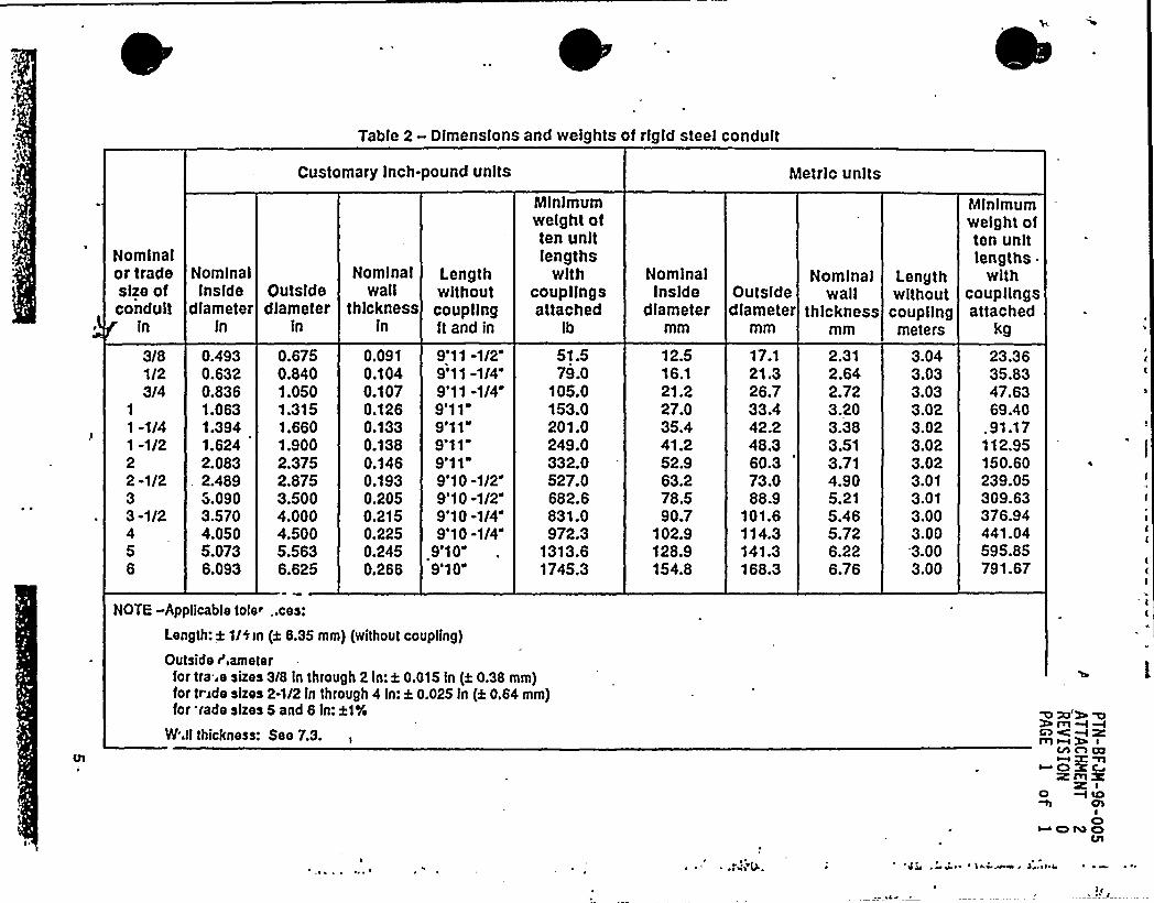
Table 2- Dimensions and weights of rlgld steel conduit
Nominalor tradesize ofconduit
ln
Nominalinside
diameterin
Customary Inch-pound units
Nominal LengthOutside wall withoutdiameter thickness coupling
in ln ft and in
Minimumweight often unitlengths
withcoup lingsattached
Ib
Nominalinside
diameter
Metric units
Nominal Leng thOutside wall withoutdiameter thickness coupling
mm mm meters
Mlnlmumweight often unitlengths
withcouplingsattached
kg
3/81/23/4
1
1 -1/41 -1/222-1/233 -1/2
56
0.4930.6320.8361.0631.3941.6242.083
. 24893.0903.5704.0505.0736.093
0.6750.8401.0501.3151.6601.9002.3752.8753.5004.0004.5005.5636.625
0,0910.1040.1070.1260.1330.1380.1460.1930.2050.2150.2250.2450.266
9'11 -1/2"9'11 -1/4"9'11 -1/49'119'119'11"9'119'10 -1/29'10 -1/2"9'10 -1/49'10 -1/4"
9e1 Qe
9'10"
51879.0
105.0153.Q201.0249.0332.0527.0682.6831.0972.3
1313.61745.3
12.516.121.227.Q35.441.252.963.278.590.7
102.9128.9154.8
17.121.326.733A42.248.360.373.088.9,
101.6114.3141.3168.3
2.312.642.723.203.383.513.714.905.215.465.726.226.76
3.043.033.033.023.023.023.023.013.013.003.003.003.00
23.3635.8347.6369.40
. 91.17112.95150.60239.05309.63376.94441.04595.85791.67
NOTE -Applicable toie~ ..ces:
Length: ~ 1/0 <n (t B.35 mm) (without coupling)
Outside r',ameterfor tra..e sizes 3/8 in through 2 In: k 0.015 in (a 0.3B mm)for triode sizes 2-1/2 ln through 4 ln: a 0.025 ln (k 0.64 mm)for sade sizes 5 and B ln:H%
W.ll thickness: See 7.3.
0 X) W %W m m -Im~~
Ch A Cl~Cl%CRmX
I0 +lbChI
~ONO

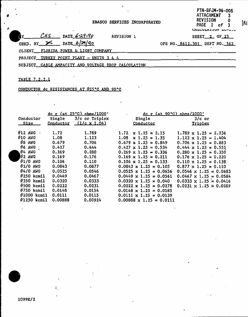
EBASCO SERVICES INCORPORATED
PTN-BFJM-96-005ATTACHMENT 3REVlSION 0PAGE 1 of 3
UALuULALlvl'I ou vwv
Y DATE 4-2'/-VO
CHKD. BY W DATE~b9t a
CLIENT
PROJECT
SUBJECT
REVISION 1
OFS NO.
SHEET~ OF~
Conductor Single 3/c or TriplexC
SingleCamhu;hu.
3/c orTxiylm
812 AWG
810 AWG
88 AWG
86 AWG
84 AWG
N2 AWG
81/0 AWG
82/0 AWG
N4/0 AWG
8250 kcmil8'350 kcmil8500 kcmil8750 kc ilf11000 kcmil81250 kcmil
1.721.080.6790.4270.2690.1690.1060.08430.05250.04490.03200.02220.01480.01110.00888
1 ~ 7891.1230.7060.4440.2800.1760.1100.08770.05460.04670.0333
.- 0.02310.01540.01150.00924
1.72 x 1.25 ~ 2.151.08 x 1.25 = 1.350.679 x 1.25 = 0.8490.427 x 1.25 = 0.5340.269 x 1.25 ~ 0.3360.169 x 1.25 = 0.2110.106 x 1.25 ~ 0.1330.0843 x 1.25 = 0.1050.0525 x 1.25 = 0.06560.0449 x 1.25 = 0.05610.0320 x 1.25 = 0.0400.0222 x 1.25 = 0.02780.0148 x 1.25 = 0.01850.0111 x 1.25 ~ 0.01390.00888 x 1.25 = 0.0111
1. 789 x 1. 25 = 2. 2361.123 x 1.25 = 1.4040.706 x 1.25 = 0.8830.444 x 1.25 = 0.5550.280 x 1.25 = 0.3500.176 x 1.25 = 0.2200.110 x 1.25 = 0.1380.877 x 1.25 = 0.1100.0546 x 1.25 = 0.06830.0467 x 1.25 = 0.05840.0333 x 1.25 = 0.04160.0231 x 1.25 ='.0289
1099E/2
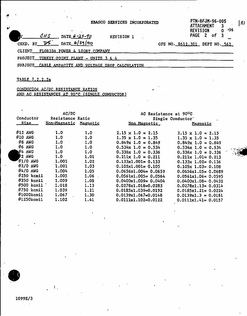
yl
e,~e~CHKD. BY
CLIENT
PROJECT
SUBJECT
EBASCO SERVICES INCORPORATED
DATE 4-2f-fODATE~62g !0
REVISION 1
PTN-BFJH-96-005ATTACHHENT 3REVISION 0 '96PAGE 2 of 3
OFS NO.~ DEPT NO.~
X6MX 7~~i
ConductorAC/DC
Resistance RatioAC Resistance at 90oC
Single Conductor'@uuJM
N 12 AWG
810 AWG
88 AWG
86 AWGI4 AWG
2 AWG
01/0 AWG
82/0 AWG
84/0 AWG
8250 kcmil8350 kcmilfbop kcmil
'750kc il81000kcmilN1250kcmil
1.01.01.01.01.01.01.0011.0011.0041.0051.0091.0181.0391.0671.102
1.01.01.01.01.01.011.021.031.051.061.081.131.211.301.41
2.15 x 1.0 = 2.151.35 x 1.0 ~ 1.350.849x 1.0 ~ 0.8490.534x 1.0 = 0.5340.336x 1.0 = 0.3360.211x 1.0 ~ 0.2110.133xl.ppl~ 0.1330.105K1.001= 0.1050.0656xl.004= 0.06590.0561x1.005~ 0.05640.0400x1.009= 0.04040.0278x1.018&.02830.0185x1.039~0.01920.0139xl.067~0.0148O.plllxl.102~0.0122
2.15 x 1.0 =1.35 x 1.0 =0.849x 1.0 =0.534x 1.0 =0.336x 1.0 =0.21lx 1.01=0.133x 1.02=0.105x 1.03=0.0656x1.05=0.0561x1.06=0.0400x1.08=0.0278xl.13=0.0185x1.21=0.0139xl.3 ~0.0lllx1.41=
2.151.350.8490.5340.3360.2130.1360.1080.06890.05950.04320.03140.02240.01810.0157
1099E/3
k',"i~~iti
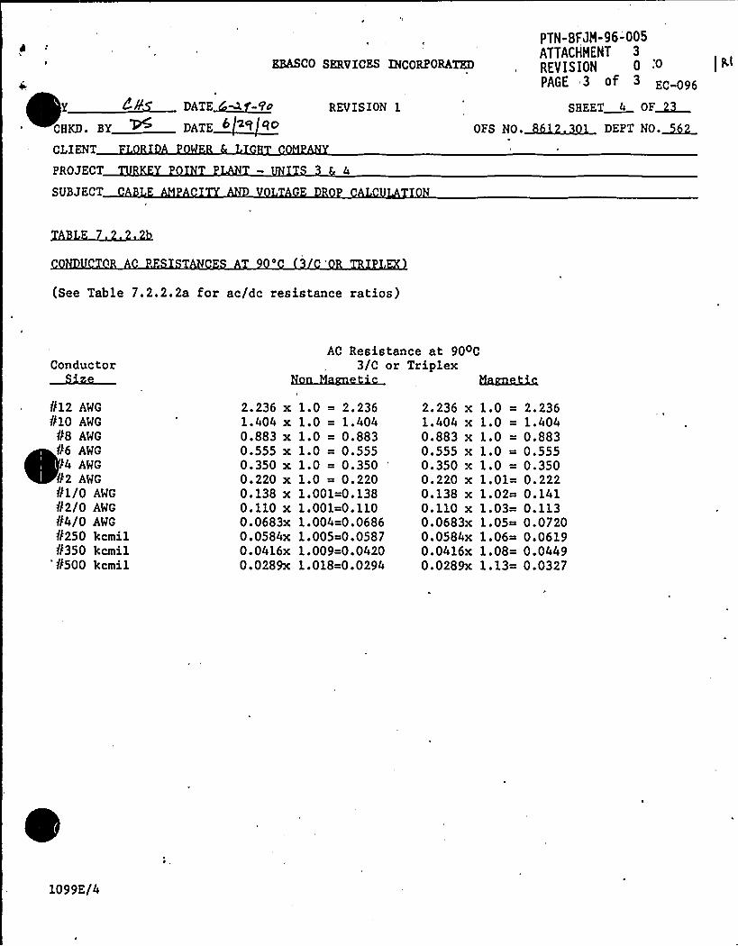
*~a~CHKD. BY
EBASCO SERVICES INCORPORATED
DATE~M
DATE~62q ED
REVISION
PTN-BFJM-96-005ATTACHMENT 3
REVISION 0PAGE 3 of 3 EC-096
SHEET 4 OF~2
OFS NO.~~ DEPT NO.~CLIENT
PROJECT
SUBJECT G D
(See Table 7.2.2.2a for ac/dc resistance ratios)
ConductorAC Resistance at 90oC
3/C or TriplexHarm~
812 AWG
810 AWG
88 AWG
86 AWG
I4 AWG
82 AWG
81/0 AWG
82/0 AWG
N4/0 AWG
f/250 kcmil8350 kcmil
'8500 kcmil
2.236 x1.404 x0.883 x0.555 x0.350 x0.220 x0.138 x0.110 x0.0683x0.0584x0.0416x0.0289x
1.0 = 2.2361.0 = 1.4041.0 = 0.8831.0 = 0.5551.0 = 0.3501.0 = 0.2201.001=0.1381.001=0.1101.004=0.06861.005~0.05871.009=0.04201.018=0.0294
2.236 x1.404 x0.883 x0.555 x0.350 x0.220 x0.138 x0.110 x0.0683x0.0584x0.0416x0.0289x
1.0 =1.0 =1.0 =1.0 =1.0 =1.01=1.02=1.03=1.05=1.06~1.08=1.13=
2.2361.4040.8830.5550.3500.2220.1410.1130.07200.06190.04490.0327
1099E/4
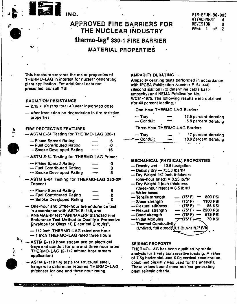
INC.
APPROVED FIRE BARRlERS FORTHE RUClEAR INDUSTRY
thermO-hg'30-1 FIRE BARRIER
MATERIAL PR 0 PER TIfS
PTN-BFJM-96-005ATTACHHENT 4REVISION 0PAGE I of 2
This brochure presents the major properties ofTHERMO-LAG in interest for nuclear generatingplant application. For additional data not
'resented.consult TSI.
RADIATIONRESISTANCE—2.12 x 1P rads total 40 year integrated dose
—After irradiation no degradation in fire resistiveproperties
FIRE PROTECTIVE FEATURES—ASTM E-84 Testing for THERMO-LAG 330-1
—Flame Spread Rating 5—Fuel Contributed Rating —,0 .
- Smoke Developed Rating — 15
—ASTM E-84 Testing for THERMO-LAG Primer—Flame Spread Rating 0—Fuel Contributed Rating — 0—Smoke Developed Rating — 5
—ASTM E-84 Testing for THERMO-LAG 350-2PTopcoat—Flame Spread Rating 5—Fuel Contributed Rating — 0—Smoke Developed Rating — 0
—One-hour and;hTee-hour fire endurance testin accordance with ASTM E-119, and
. ANI/MAERPtest "ANI/MAERPStandard FireE'ndurance Test Method to Qualify a ProtectiveEnvelope for Class 1E Electrical Circuits".—1/2 Inch THERMO-LAG rated one hour—1 inch THERMO-LAG rated three hours
. —ASTM E-119 hose stream test on electricaltrays and conduit for one and thrcc hour ratedTHERMO-LAG (2-1/2 minute hose streamapplication)
~~—ASTM E-119 fire tests for structural steel,
hangers to determine required THERMO-LAGthickness for onc and three hour rating
—Tray.=—Conduit17 percent derating
10.9 percent derating
MECHANICAL(PHYSICAI-) PROPORTIES—Density wet —10.5 lbs/gallon—Density dry —75~3 Ibs/ft3—Dry Weight 1/2 inch thickness
(one*our rated) ~ 3.25 Ib/Its—Dry Weight 1 inch thickness
(three-hour rated) ~ 6.5 Ib/ltz—Venter based—Tensile strength (75'F) — 800 PSI—Shear strength —(75'F) —1100 PSI—Flexural stiffness —(75'F) 85 KSI—Flexural strength —(75'F) —2200 PSI-Bond strength —(75'F) —575 PSI—initial Modulus ~~'F) — 70 KSI—Thermal Conductivity
(Unfired. full cured) 0.1 Btu/hr ft.z'F/
SEISMIC PROPORTYTHERMO-LAG has been qualified by staticanalysis for a very conservative loading. A valueof 7.5g horizontal ~ and 6.0g vertical acceleration,combined biaxially was used for the analysis.These values bound most nuclear generatingplant seismic criteria.
AMPACITYDERATINGAmpacity derating tests performed in accordancewith IPCEA Publication Number P-54-440(Second Edition) (to determine cable baseampacity) and NEMA Publication No.WC51-1975, The following results were obtained(for 40 percent loading):
One-Hour THERMO-LAG Barriers
—Tray — 12.5 pere'ent derating—Conduit — 6.8 percent derating
Three-Hour THERMO-LAG Barriers
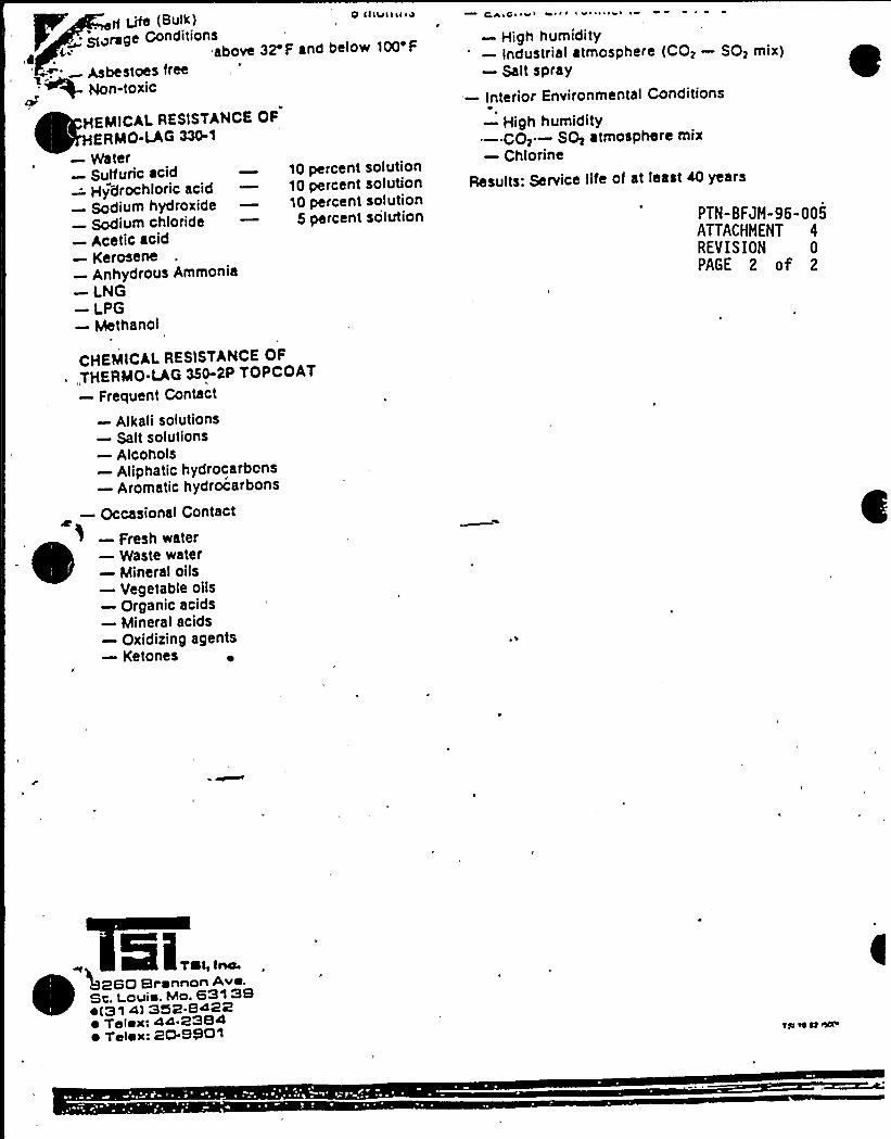
10 percent solution10 percent solution10 percent solution
5 percent solution
(Bulk) 0 (Ilute>ar se
- ><rage Conditions
(aabove 32'F and below 100 F
Asbestoes freeNon-toxic
HEMICALRESISTANCE OFERMO-LAG 330-1
—Water—Sulfuric acid—Hydrochloric acid—Sodium hydroxide—Sodium chloride—Acetic acid—Kerosene—Anhydrous Ammonia—LNG—LPG—Methanol
C'P ~ C ~l w t ~ l I ~ ~ ~ lwl
—High humidity—Industrial atmosphere (CO> —SO> mix)—Salt spray
—Interior Environmental Conditions
—High humidity—CO> —S+ atmosphere mix—Chlorine
Results: Service life of at least 40 years
PTN-BFJH-96-005ATTACHMENT 4REVISION 0PAGE 2 of 2
CHEMICALRESISTANCE OF~ „THERMO-LAG3$ 0-2P TOPCOAT
—Frequent Contact
—Alkali solutions—Salt solutions—Alcohols—Aliphatic hydrocarbons—Aromatic hydrocarbons
—Occasional Contact
—Fresh water—Waste water—Mineral oils—Vegetable oils—Organic acids—Mineral acids—Oxidizing agents—Ketoncs ~
Si,.„, ~~
260 Brennon Ave.Sc. I ouie. Mo. 631 38~ (31 4) 352 8422~ Telex: 44-2384~ Telex: 20-8601