Embed Size (px)
Citation preview

ECE 344
Microwave Fundamentals
Assistant ProfessorDr. Gehan Sami

Course Objectives
The course aimed to:
Describe principles of microwave engineering and technology.
Derive and solve the wave equations in many microwave structures such as transmission lines and waveguides to analyze the wave propagation along them.
Use of Smith chart for determining the wave characteristics on a transmission line and determine the input impedance and calculate perform the impedance matching .
Investigate different passive microwave components such as: power dividers/combiners, couplers, resonators and cavities.

No. Topics
1 Course Objectives and Outline & Review of Electromagnetic Fields
2 General Transmission Line Theory & Circuit Model of Transmission lines
3 General Transmission Line Equations & Standing Wave Properties
4 Transmission Line Parameters & Lossless Transmission Line
5 Matching techniques - Quarter wavelength transformer - Smith chart - Single stub matching-Double stub matching
6 Advanced Design System (ADS) program- Simulation for microwave circuits
7 Rectangular Waveguide
8 Power transmitted in rectangular waveguide
9 Microstrip Transmission Line Structure &Stripline Transmission Line Structure
10 Microwave network analysis-S matrix-Z matrix-Y matrix-ABCD matrix
11 Microwave Passive devices- analyze and design Directional coupler
12 Microwave Passive devices- analyze and design Power dividers
Course Contents

List of ReferencesTextbook:
D.M. Pozar “Microwave Engineering”, third edition, Wiley publishing
• Related readings:
R.E. Collin “Foundations for microwave engineering”, McGraw-Hill, 2nd
ed., 1992
-ECE 5317_6351 Microwave Engineering Prof. David R. Jackson
Simulators
- HFSS High Frequency Structure Simulator.
- ADS Advanced Design System
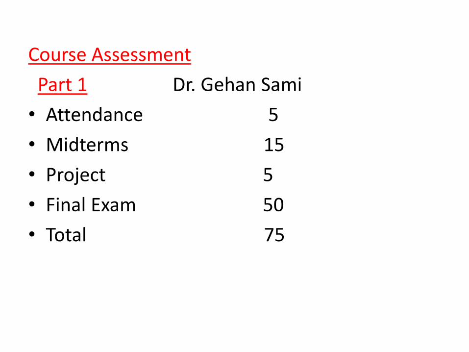
Course Assessment
Part 1 Dr. Gehan Sami
• Attendance 5
• Midterms 15
• Project 5
• Final Exam 50
• Total 75

Introduction• Microwave refer to alternating signals with frequencies between 300MHz
and 300GHz,with wavelength between λ=c/f=1m and 1mm.

• Why we use microwaves
microwave signals offer wide bandwidths, and have the added advantage of being ableto penetrate fog, dust, foliage, and even buildings and vehicles to some extent
Microwaves are widely used for point-to-point communications because their small wavelength allows conveniently-sized antennas to direct them in narrow beams, which can be pointed directly at the receiving antenna
high frequency of microwaves gives the microwave band a very large information-carryingcapacity.
Gain of a Typical 6 Foot Dish Antenna (with Losses)
Antenna gain is proportional to the electric size of theantenna. for Dish antenna physical size almost equal to
Electrical size
f ↑, gain ↑

Microwave ApplicationsThree main applications of microwaves in everyday life:
1- Heating-Microwave ovens
2- Remote sensing- Radars (radio direction and ranging),detect object position or velocity (or both).- RFID
-Radio astronomy
3- Communications-satellite, radio, television, wireless phone and data transmission applications
• Other applications as:-Medical applications
-Directed energy weapons
https://www.microwaves101.com/

Microwave ovens
Microwave Applications
f=2.45GHz

RFID System
Microwave Applications

Microwave ApplicationsMedical applicationsPatient monitoring

Microwave ApplicationsMedical applications
Free-range Resonant Electrical Energy DeliverySystem (FREE-D) for a Ventricular Assist Device
University of Washington
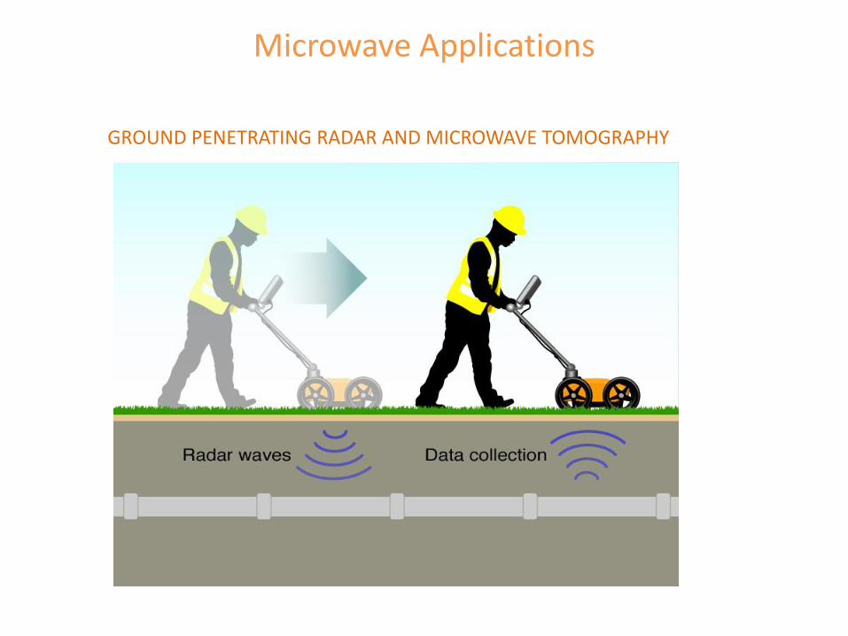
GROUND PENETRATING RADAR AND MICROWAVE TOMOGRAPHY
Microwave Applications
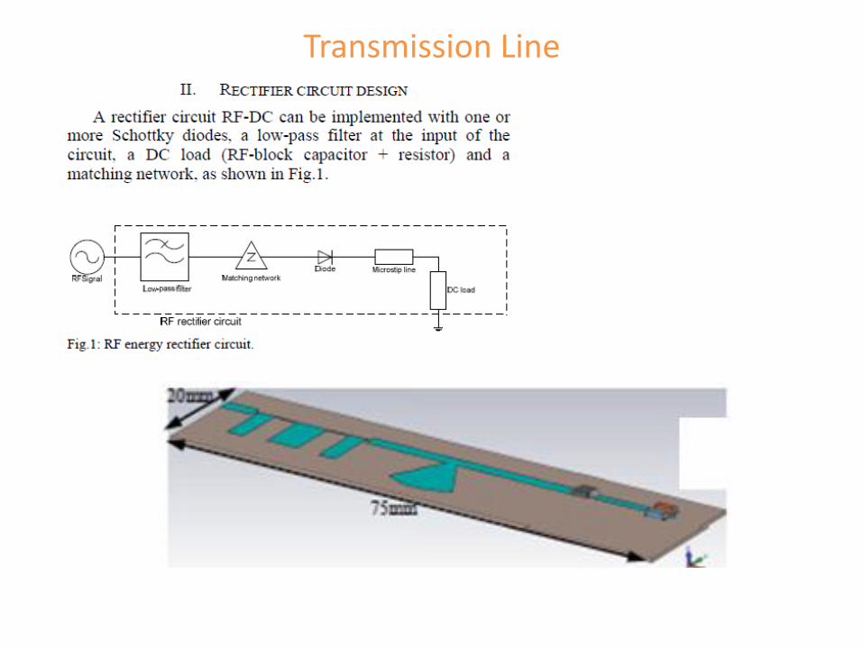
Transmission Line

A Monolithic Microwave Integrated
Circuit, or MMIC
(sometimes pronounced "mimic"), is a type
of integrated circuit (IC) device that
operates
at microwave frequencies (300 MHz to
300 GHz). These devices typically perform
functions such as microwave mixing,
power amplification, low-noise
amplification, and high-frequency
switching. Inputs and outputs on MMIC
devices are frequently matched to
a characteristic impedance of 50 ohms.
This makes them easier to use, as
cascading of MMICs does not then require
an external matching network.
.

Transmission Line

Transmission Line

Planar Transmission Lines •Microstrip.
•Slot Line.
•Coplanar waveguide.
•Coplanar lines.
Transmission Line
Can propagate a signal at any frequency (in theory) Becomes lossy at high frequency Can handle low or moderate amounts of power
Does not have Ez or Hz components of the fields (TEMz)
Properties
Coaxial cable (coax)

Transmission Line (cont.)
Microstrip
h
w
er
er
w
Stripline
h
Transmission lines commonly met on printed-circuit boards
Coplanar strips
her
w w
Coplanar waveguide (CPW)
her
w
19

Fiber-Optic Guide
Has minimal signal distortion Very immune to interference Not suitable for high power
Has both Ez and Hz components of the fields
Properties
Wave guides

Waveguides
Has a single hollow metal pipe
Can propagate a signal only at high frequency: > c
The width must be at least one-half of a wavelength Has signal distortion, even in the lossless case Immune to interference Can handle large amounts of power Has low loss (compared with a transmission line)
Has either Ez or Hz component of the fields (TMz or TEz)
Properties
http://en.wikipedia.org/wiki/Waveguide_(electromagnetism) 21

Transmission Line (cont.)
Transmission lines are commonly met on printed-circuit boards.
A microwave integrated circuit
Microstrip line
22

Lumped circuits: resistors, capacitors, inductors
neglect time delays (phase)
account for propagation and time delays (phase change)
Transmission-Line Theory
Distributed circuit elements: transmission lines
We need transmission-line theory whenever the length of a line is significant compared with a wavelength.
23
electrical wavelength is much larger than the physical dimension of the circuits

Transmission Line
2 conductors
4 per-unit-length parameters:
C = capacitance/length [F/m]
L = inductance/length [H/m]
R = resistance/length [/m]
G = conductance/length [ /m or S/m]
Dz
24
An engineering problem is to transfer signal from generator to load.
A transmission line is a part of circuit that link between generator and load; Theory of
transmission line applied on all types of transmission lines.

Transmission Line (cont.)
zD
,i z t
+ + + + + + +- - - - - - - - - - ,v z tx x xB
25
RDz LDz
GDz CDz
z
v(z+Dz,t)
+
-
v(z,t)
+
-
i(z,t) i(z+Dz,t)
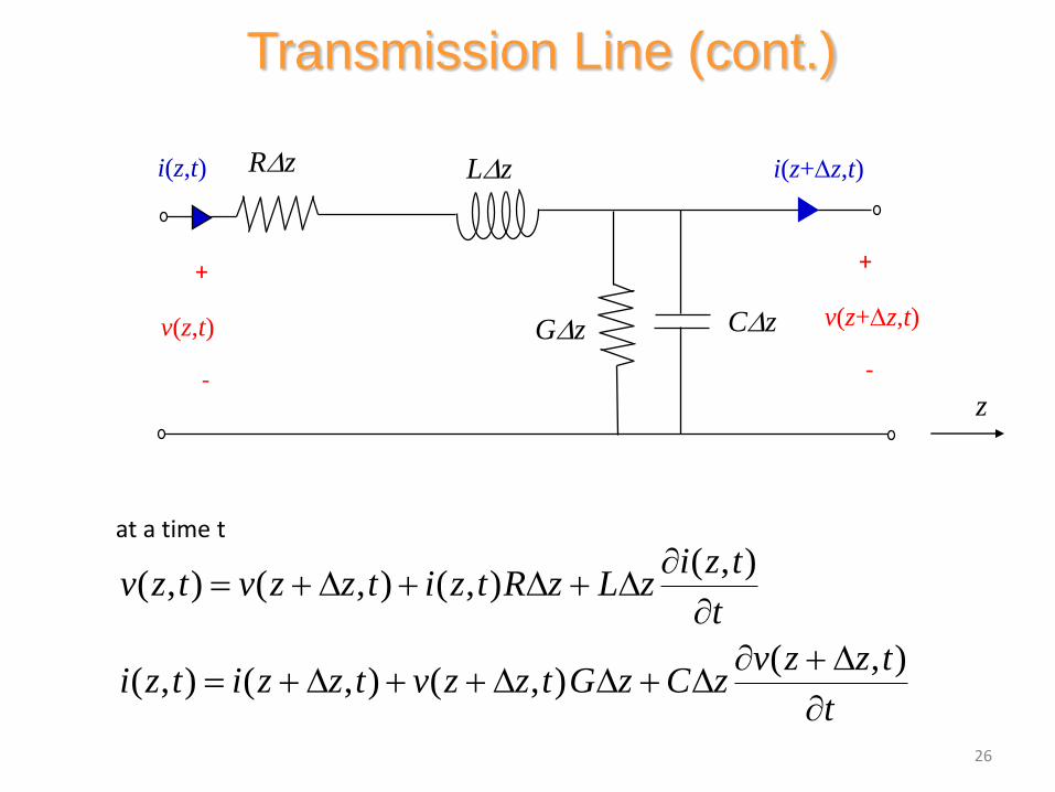
( , )( , ) ( , ) ( , )
( , )( , ) ( , ) ( , )
i z tv z t v z z t i z t R z L z
t
v z z ti z t i z z t v z z t G z C z
t
D D D
D D D D D
Transmission Line (cont.)
26
RDz LDz
GDz CDz
z
v(z+Dz,t)
+
-
v(z,t)
+
-
i(z,t) i(z+Dz,t)
at a time t

Hence
( , ) ( , ) ( , )( , )
( , ) ( , ) ( , )( , )
v z z t v z t i z tRi z t L
z t
i z z t i z t v z z tGv z z t C
z t
D
D
D D D
D
Now let Dz 0:
v iRi L
z t
i vGv C
z t
“Telegrapher’sEquations”
TEM Transmission Line (cont.)
27

2 2
2 2( ) 0
v v vRG v RC LG LC
z t t
The same equation also holds for i.
Hence, we have:
2 2
2 2
v v v vR Gv C L G C
z t t t
TEM Transmission Line (cont.)
28

2
2
2( ) ( ) 0
d VRG V RC LG j V LC V
dz
2 2
2 2( ) 0
v v vRG v RC LG LC
z t t
TEM Transmission Line (cont.)
Time-Harmonic Waves:
29

Note that
= series impedance/length
2
2
2( )
d VRG V j RC LG V LC V
dz
2( ) ( )( )RG j RC LG LC R j L G j C
Z R j L
Y G j C
= parallel admittance/length
Then we can write:
2
2( )
d VZY V
dz
TEM Transmission Line (cont.)
30

Let
Convention:
Solution:
2 ZY
( ) z zV z Ae Be
1/2
( )( )R j L G j C
principal square root
2
2
2( )
d VV
dzThen
TEM Transmission Line (cont.)
is called the "propagation constant."
/2jz z e
j
0, 0
attenuationcontant
phaseconstant
31
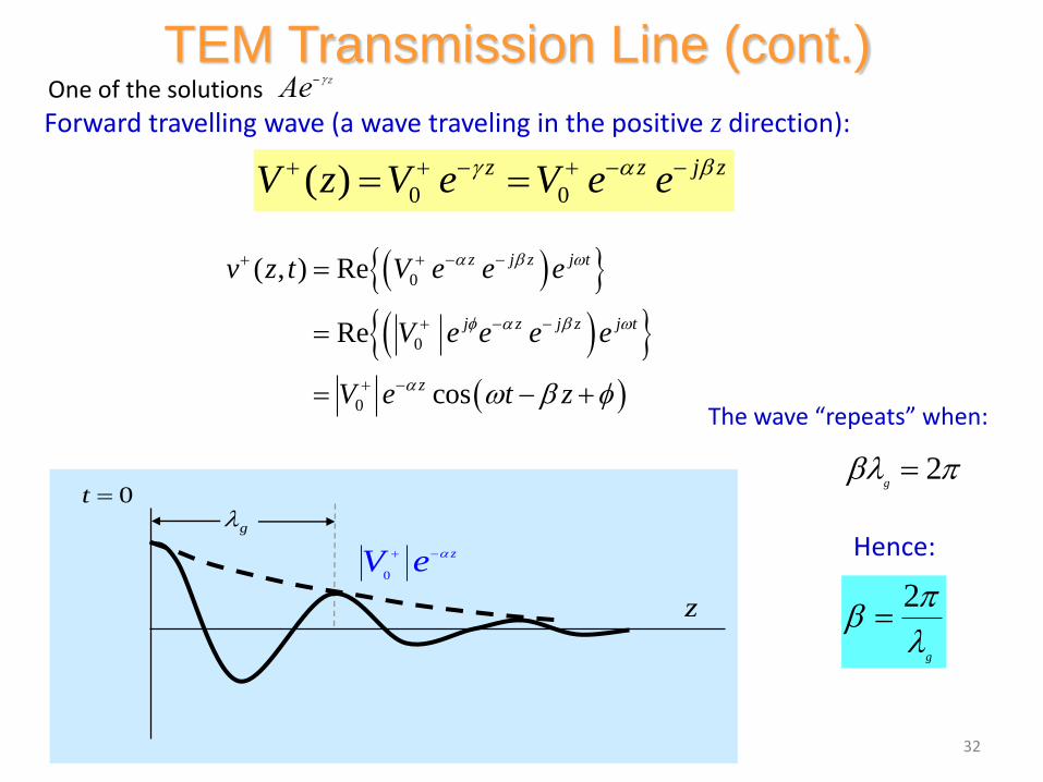
TEM Transmission Line (cont.)
0 0( ) z z j zV z V e V e e
Forward travelling wave (a wave traveling in the positive z direction):
0
0
0
( , ) Re
Re
cos
z j z j t
j z j z j t
z
v z t V e e e
V e e e e
V e t z
g0t
z
0
zV e
2
g
2g
The wave “repeats” when:
Hence:
32
One of the solutions

Phase Velocity
Track the velocity of a fixed point on the wave (a point of constant phase), e.g., the crest.
0( , ) cos( )zv z t V e t z
z
vp (phase velocity)
33

Phase Velocity (cont.)
0
constant
t z
dz
dt
dz
dt
Set
Hencep
v
1/2
Im ( )( )p
vR j L G j C
In expanded form:
34

Characteristic Impedance Z0
0
( )
( )
V zZ
I z
0
0
( )
( )
z
z
V z V e
I z I e
so 00
0
VZ
I
+
V+(z)
-
I+ (z)
z
A wave is traveling in the positive z direction.
(Z0 is a number, not a function of z.)
35
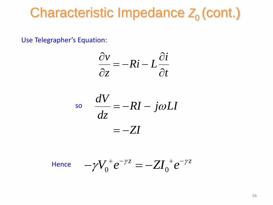
Use Telegrapher’s Equation:
v iRi L
z t
sodV
RI j LIdz
ZI
Hence0 0
z zV e ZI e
Characteristic Impedance Z0 (cont.)
36

From this we have:
Using
We have
1/2
00
0
V Z ZZ
I Y
Y G j C
1/2
0
R j LZ
G j C
Characteristic Impedance Z0 (cont.)
Z R j L
Note: The principal branch of the square root is chosen, so that Re (Z0) > 0.
37

• a fundamental parameter of transmission
line is its characteristic impedance z0 and
propagation constant γ.
z0 describe the relation between the
current and voltage travelling waves
z0 is function of dimensions of T.L. and
dielectric constant
for most RF systems z0 is either 50 or 75
ohms.(Notice z0 is real for low losses)
For low power (cable TV for example ) coaxial lines are optimized for low loss z0 =75 ohms,
for radar applications high power is encountered coaxial line is designed to compromise
Between max power handling and minim um losses ,it designed to have z0 =50 ohm
Characteristic impedance of transmission line:

appendix J for standard
coaxial cable, most designed
for z0 between 50-75

00
0 0
j z j j z
z z
z j zV e e
V z V e V
V e e e
e
e
0
0 cos
c
, R
os
e j t
z
z
V e t
v z t V z
z
V z
e
e t
Note:
wave in +z
direction wave in -zdirection
General Case (Waves in Both Directions)
40

Backward-Traveling Wave
0
( )
( )
V zZ
I z
0
( )
( )
V zZ
I z
so
+
V -(z)
-
I - (z)
z
A wave is traveling in the negative z direction.
Note: The reference directions for voltage and current are the same as for the forward wave.
41

General Case
0 0
0 0
0
( )
1( )
z z
z z
V z V e V e
I z V e V eZ
A general superposition of forward and backward traveling waves:
Most general case:
Note: The reference directions for voltage and current are the same for forward and backward waves.
42
+
V (z)
-
I (z)
z

1
2
12
0
0 0
0 0
0 0
z z
z z
V z V e V e
V VI z e e
Z
j R j L G j C
R j LZ
G j
Z
C
I(z)
V(z)+
-z
2
mg
[m/s]pv
guided wavelength g
phase velocity vp
Summary of Basic TL formulas
43
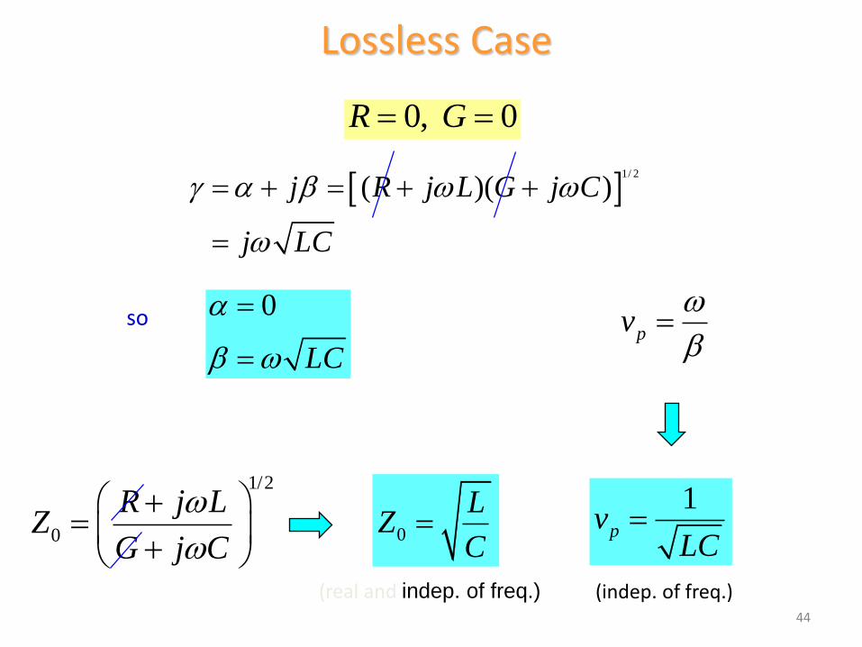
Lossless Case
0, 0R G
1/ 2
( )( )j R j L G j C
j LC
so 0
LC
1/2
0
R j LZ
G j C
0
LZ
C
1pv
LC
pv
(indep. of freq.)(real and indep. of freq.)44

Lossless Case (cont.)
1pv
LC
In the medium between the two conductors is homogeneous (uniform) and is characterized by (e, ), then we have that
LC e
The speed of light in a dielectric medium is1
dce
Hence, we have that p dv c
The phase velocity does not depend on the frequency, and it is always the speed of light (in the material).
(proof given later)
45