Embed Size (px)
Citation preview
MOE 506 LNG Processing, Storage, Transport, Re-gasification, Distribution and Usage
1
Assignment 2
Prepare an outline specification for an LNG
plant located at Vasilikos, Cyprus
Authors: Supervisor:
Nikolaos G. Felessakis Dr Richard J Barnes
(8653)
MOE 506 LNG Processing, Storage, Transport, Re-gasification, Distribution and Usage
2
Introduction ............................................................................................................................................. 4
1. LNG plant process and capacity ................................................................................................. 5
1.1 Introduction to LNG processing ......................................................................................... 5
1.2 Feed Gas Processing ............................................................................................................... 7
1.2.1 Inlet Separation and Treatment System .................................................................................. 7
1.2.2 Acid Gas Removal System .............................................................................................................. 8
1.2.2.1 Acid Gas Removal ..................................................................................................................................... 8
1.2.3 Dehydration System ......................................................................................................................... 8
1.2.4 Mercury Removal System .............................................................................................................. 9
1.3 Liquefaction .............................................................................................................................. 9
1.3.1 Liquefaction System ......................................................................................................................... 9
1.3.2 Refrigeration System .................................................................................................................... 10
1.4 Sources of gas, design rate and project life .................................................................. 10
2. Pipeline connection ..................................................................................................................... 12
2.1 Pipeline Technical Characteristics ................................................................................. 12
2.2 Coatings .................................................................................................................................... 13
2.3 Pipeline calculations ............................................................................................................ 13
2.3.1 Outlet pressure ................................................................................................................................ 13
MOE 506 LNG Processing, Storage, Transport, Re-gasification, Distribution and Usage
3
2.3.2 Wall thickness .................................................................................................................................. 14
3. LNG export facilities and loading frequency ....................................................................... 16
3.1 LNG Jetty Type ........................................................................................................................ 16
3.2 The loading arms .................................................................................................................. 17
3.2.1 LNG serve and uploading time ................................................................................................. 17
4. LNG storage tank size, type and quantity ............................................................................. 18
5. Bibliography .................................................................................................................................. 20
TABLE 1.4-‐1PRODUCTION VOLUME RELATED WITH RESOURCES AND THE SIZE OF THE LNG PLANT ............................... 11
TABLE 2.3-‐1 Q FLOW RATE CALCULATIONS ................................................................................................................................. 14
TABLE 2.3-‐2 PIPE OUTLET WALL THICKNESS .............................................................................................................................. 15

MOE 506 LNG Processing, Storage, Transport, Re-gasification, Distribution and Usage
4
Introduction
This project aims to describe the outline of Liquefied natural gas (LNG) plant in
Vasilikos area from the potential reserves of the Aphrodite field.
MOE 506 LNG Processing, Storage, Transport, Re-gasification, Distribution and Usage
5
1. LNG plant process and capacity
The natural gas is inherently a domestic product. As gas, the hydrocarbon must
be transported by pipeline, which reduces the number of recipients. Liquefied
Natural Gas (LNG) was developed in 1964 as a solution to this problem. That
solution entails the following: LNG gas is being liquefied and transported
internationally via tankers and then regasified into its original state for distribution
and sale1.
1.1 Introduction to LNG processing
There is no typical or standard LNG plant. The major elements that are found in
most LNG plants include:
− Feed gas Processing
• Inlet Separation and treatment
• Acid gas removal
• Dehydration and Mercury removal
− Liquefaction
• Refrigeration System
− Fractionation
− Plant Utilities
• Hot Oil System
− Storage
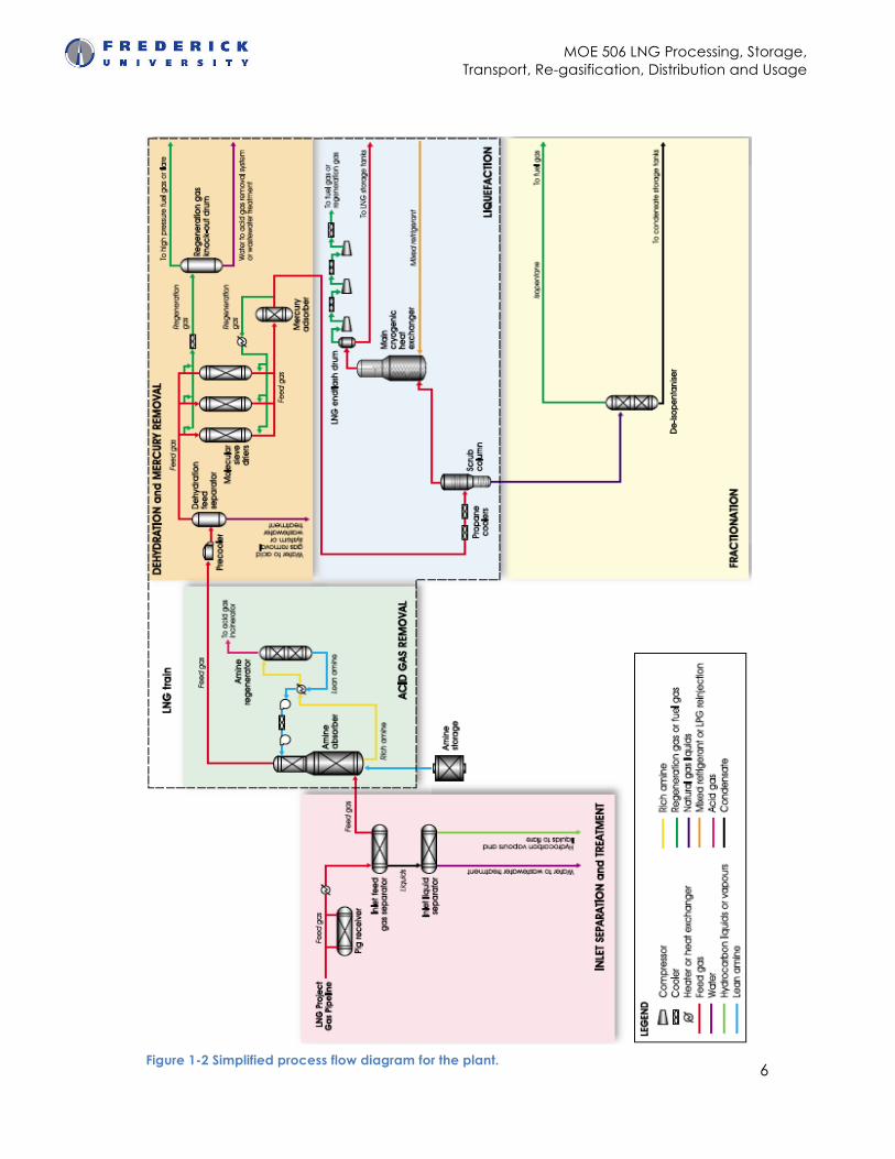
The LNG Plant will receive gas from the LNG Project Gas Pipeline, treat it and then
liquefy it using refrigerants. Figure 1-1 illustrates the simplified process flow
diagram for the plant.
1 http://www.rigzone.com/training/insight.asp?i_id=322
MOE 506 LNG Processing, Storage, Transport, Re-gasification, Distribution and Usage
6 Figure 1-2 Simplified process flow diagram for the plant.
MOE 506 LNG Processing, Storage, Transport, Re-gasification, Distribution and Usage
7
Specifically, the LNG Plant will:
• Heat the incoming gas from the pipeline,
• Reduce its pressure, and remove any liquids entrained with the gas,
• Remove acid gas, residual moisture and mercury,
• Liquefy the feed gas and
• Fractionate the hydrocarbon liquids produced during the liquefaction
process into condensate (pentane and heavier hydrocarbons) for export.
1.2 Feed Gas Processing
1.2.1 Inlet Separation and Treatment System
The inlet facilities at the LNG Plant will receive a single-phase gas from the
Pipeline network at a pressure of 6,750 kPag and a temperature of 30°C. The gas
will have been conditioned to a water and hydrocarbon dew point of 5°C at the
Hides Gas Conditioning Plant (Exxon Mobil, 2013)
The hot oil system will heat the gas to prevent hydrate formation and to meet the
amine absorber feed gas temperature requirement. The warmed gas will be
depressurized and flow to the inlet feed gas separator, which will remove small
liquid slugs. The inlet liquids separator will receive these liquids (if present) and
send the hydrocarbons to fractionation for processing into condensate. The
produced water stream will be sent to the wastewater treatment system for
disposal.
Feed gas from the inlet feed gas separator will be metered ahead of final
treatment before liquefaction to remove acid gas, residual water and traces of
mercury.
MOE 506 LNG Processing, Storage, Transport, Re-gasification, Distribution and Usage
8
1.2.2 Acid Gas Removal System
Impurities in a gas stream, such as hydrogen sulfide and carbon dioxide, are
collectively referred to as acid gases. The acid gas as the carbon dioxide, it can
be freeze at cryogenic liquefaction temperatures and thereby block the natural
gas flow path. An amine solvent (amine mixed with water) will be used to remove
acid gas, as follows(idid).
1.2.2.1 Acid Gas Removal
Feed gas warmed to approximately 35°C from the metering station enters the
bottom of the amine absorber. The amine solvent enters the absorber near the
top and flows counter-current against the gas being treated, so that the freshest
solvent contacts the cleanest gas first. The solvent progressively absorbs the acid
gases and exits the bottom of the amine absorber.
The treated feed gas then flows from the top of the amine absorber to the
dehydration system. Sweetened gas can also be used as high pressure start-up
fuel gas(idid).
1.2.3 Dehydration System
The gas leaving the acid gas removal system will be saturated with water. The
dehydration system will dry the gas down to less than 0.1 ppm(v) of water to
prevent ice (hydrates) forming in the downstream cryogenic equipment. A
propane refrigerant cools the feed gas to 25°C and condenses most of the water
vapor. The dehydration feed separator returns the condensed water and solvent
carryover to the acid gas removal system as make-up.
Regeneration will be achieved with a gas stream. This regeneration gas will be
heated by the hot oil system to approximately 230°C. When a bed is
regenerating, the hot regeneration gas stream enters at the bottom of the drier
and exits at the top. The water released during regeneration will normally be
directed to the wastewater treatment system or used as make-up water for the
acid gas removal system(idid).
MOE 506 LNG Processing, Storage, Transport, Re-gasification, Distribution and Usage
9
1.2.4 Mercury Removal System
Elemental mercury corrodes aluminium, and even very low traces must be
removed to prevent damage to the cryogenic heat exchangers. The mercury
removal system will pass gas from the dehydration system through an absorber of
non-regenerative, sulfur-impregnated, activated carbon, which will chemically fix
elemental mercury as a non-volatile mercury sulfide.
After this procedure the mercury levels in the feed gas are so low that the
adsorbent may not need to be replaced during the life of the project(idid).
1.3 Liquefaction
Liquefaction uses the feed gas to below the methane boiling point of around -
161°C. At this temperature, the gas liquefies to 1/600th of its original volume.
1.3.1 Liquefaction System
The liquefaction system in an LNG train comprises propane coolers, a heavy-
hydrocarbon removal column, and cryogenic heat exchangers. Propane coolers
will cool the feed gas from the mercury removal system. The coolers liquefy the
heavier hydrocarbons, which then flow to a heavy-hydrocarbon removal
column. Heat and pressure will be used to separate the heavier hydrocarbons
from the feed gas stream in the column. These heavier hydrocarbons (ethane,
propane, butane and heavier components) will exit the bottom of the column.
The vapors will exit the top of the column and flow to the main cryogenic heat
exchanger.
The LNG will be produced at approximately 800 t/hr. The flashing process loses
some of the LNG as a vapor, which will be warmed and then compressed. Some
of this gas will be used to regenerate the molecular sieve driers in the
dehydration system before being sent to the high-pressure fuel gas system.
MOE 506 LNG Processing, Storage, Transport, Re-gasification, Distribution and Usage
10
The LNG from the liquefaction system will be pumped to the LNG storage tanks
(idid).
1.3.2 Refrigeration System
The refrigeration system cools and pressurises the refrigerants used in the
liquefaction system. The refrigeration system will use closed-loop, refrigerant
circuits to provide the low-temperature refrigerants. The refrigerants will be used
to liquefy and sub-cool the feed gas in the cryogenic heat exchangers(idid).
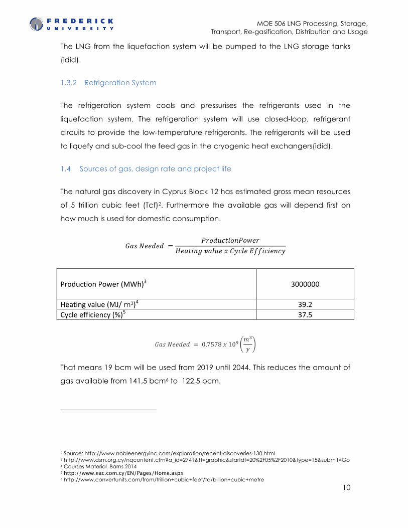
1.4 Sources of gas, design rate and project life
The natural gas discovery in Cyprus Block 12 has estimated gross mean resources
of 5 trillion cubic feet (Tcf)2. Furthermore the available gas will depend first on
how much is used for domestic consumption.
𝐺𝑎𝑠 𝑁𝑒𝑒𝑑𝑒𝑑 =𝑃𝑟𝑜𝑑𝑢𝑐𝑡𝑖𝑜𝑛𝑃𝑜𝑤𝑒𝑟
𝐻𝑒𝑎𝑡𝑖𝑛𝑔 𝑣𝑎𝑙𝑢𝑒 𝑥 𝐶𝑦𝑐𝑙𝑒 𝐸𝑓𝑓𝑖𝑐𝑖𝑒𝑛𝑐𝑦
Production Power (MWh)3 3000000
Heating value (MJ/ m3)4 39.2 Cycle efficiency (%)5 37.5
𝐺𝑎𝑠 𝑁𝑒𝑒𝑑𝑒𝑑 = 0,7578 𝑥 10!𝑚!
𝑦
That means 19 bcm will be used from 2019 until 2044. This reduces the amount of
gas available from 141,5 bcm6 to 122,5 bcm.
2 Source: http://www.nobleenergyinc.com/exploration/recent-discoveries-130.html 3 http://www.dsm.org.cy/nqcontent.cfm?a_id=2741&tt=graphic&startdt=20%2F05%2F2010&type=15&submit=Go 4 Courses Material Barns 2014 5 http://www.eac.com.cy/EN/Pages/Home.aspx 6 http://www.convertunits.com/from/trillion+cubic+feet/to/billion+cubic+metre
MOE 506 LNG Processing, Storage, Transport, Re-gasification, Distribution and Usage
11
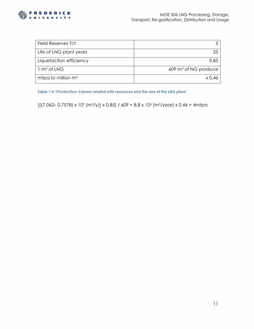
Field Reserves Tcf 5
Life of LNG plant years 25
Liquefaction efficiency 0.85
1 m3 of LNG 609 m3 of NG produce
mtpa to million m3 x 0,46
Table 1.4-1Production Volume related with resources and the size of the LNG plant
[((7,062– 0,7578) x 109 (m3/y)) x 0,85] / 609 = 8,8 x 10⁶ (m3/year) x 0,46 = 4mtpa
MOE 506 LNG Processing, Storage, Transport, Re-gasification, Distribution and Usage
12
2. Pipeline connection
Another major part of the LNG procedure is the feed process from the reserve to
the LNG plant through the pipeline connection. The offshore pipeline
construction is related with the environment parameters of the geographical
position of the reserve. This parameters are the distance between reserve and
LNG plant, the sea depth that is related with the pressure, and the temperature.
This parameters define the characteristics of the pipeline such as the Diameter,
in/out wall thickness and the material.
2.1 Pipeline Technical Characteristics
The Aphrodite-Vasilikos pipeline connection has an offshore distance
approximately 200km in 2000m sea depth. These conditions are similar with the
‘Blue Stream’ that provide a conduit for export of Russian gas directly to Turkey
with an offshore distance up to 398 km and 2150 m sea depth7.
Because of this similarity we can assume that we can use the same pipeline data
such as:
− Diameter: 24inc (=609.6 mm)
− Pressure: 250 bar in a sea depth of 2150m
− Temperature: -10ºC to +55ºC
− 32 mm wall thickness
− Flow rate ~ 2.5m/s and
− Material type carbon steel with outer coating of concrete (Shell, 2010).
7 sources: Natural gas prices from index. mundi; LNG prices from Reuters; pipeline costs from Pete Wallace, Tractebel Engineering; LNG plant cost from Minister Sylikiotis; distances from Block 12 to Vassiliko from DEFA; distance from Cyprus to Greece from DEPA; pipeline depth to Greece from Quantum Energy figures on electricity cable.
MOE 506 LNG Processing, Storage, Transport, Re-gasification, Distribution and Usage
13
2.2 Coatings
Probably, the best choice for the anti-corrosion coating is application used in the
Blue Stream. After several tests the best solution for pipeline protection in the
extreme environment of 2000m underwater depth is a three layer polypropylene
coating consisting of a first layer of fusion bonded epoxy, a second layer of
polypropylene adhesive and an outer layer of polypropylene.
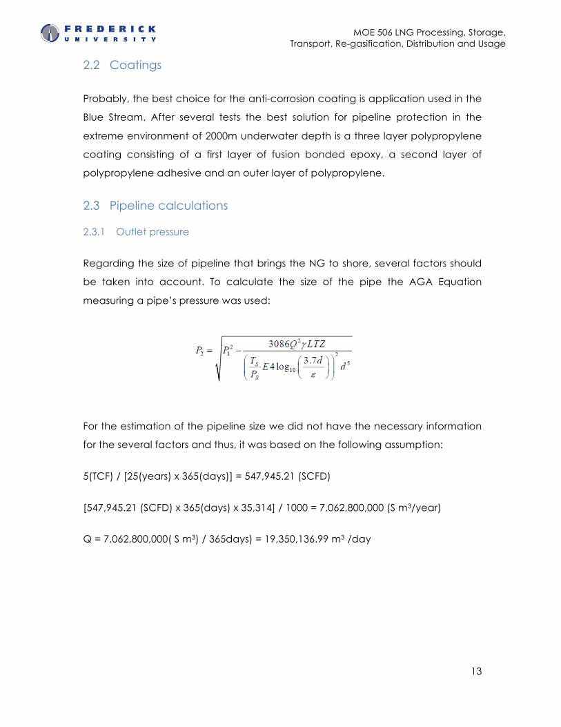
2.3 Pipeline calculations
2.3.1 Outlet pressure
Regarding the size of pipeline that brings the NG to shore, several factors should
be taken into account. To calculate the size of the pipe the AGA Equation
measuring a pipe’s pressure was used:
For the estimation of the pipeline size we did not have the necessary information
for the several factors and thus, it was based on the following assumption:
5(TCF) / [25(years) x 365(days)] = 547,945.21 (SCFD)
[547,945.21 (SCFD) x 365(days) x 35,314] / 1000 = 7,062,800,000 (S m3/year)
Q = 7,062,800,000( S m3) / 365days) = 19,350,136.99 m3 /day
MOE 506 LNG Processing, Storage, Transport, Re-gasification, Distribution and Usage
14
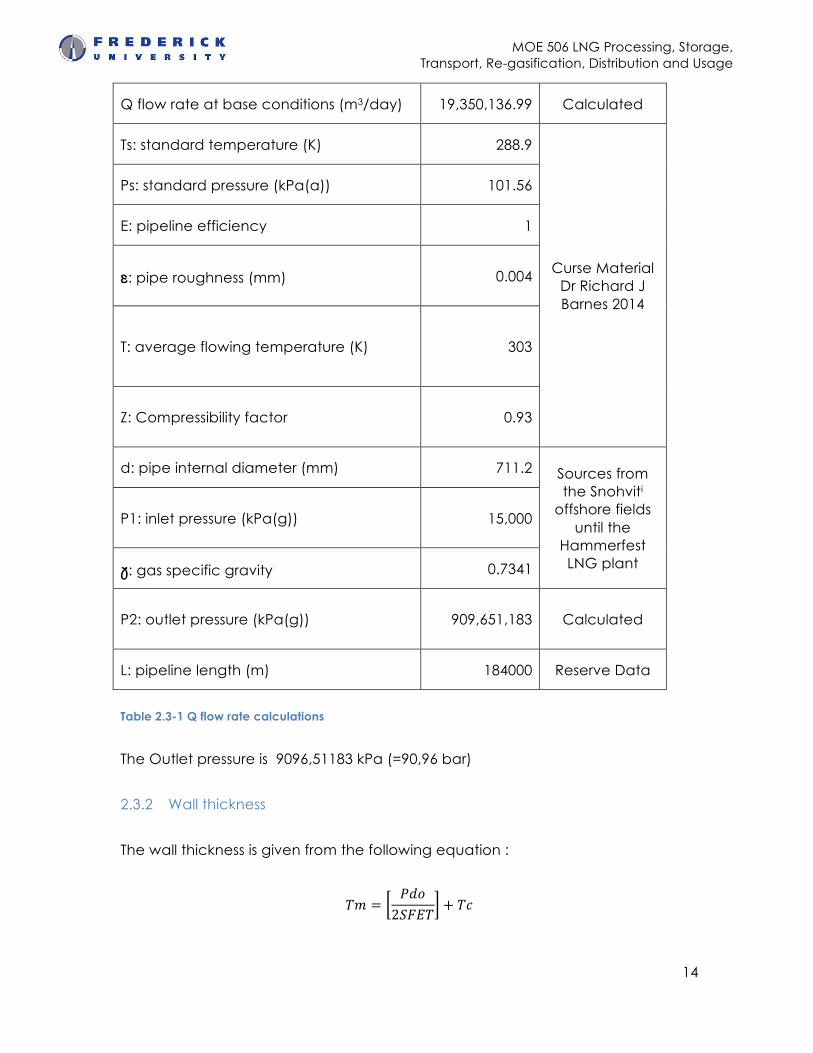
Q flow rate at base conditions (m3/day) 19,350,136.99 Calculated
Ts: standard temperature (K) 288.9
Curse Material Dr Richard J Barnes 2014
Ps: standard pressure (kPa(a)) 101.56
E: pipeline efficiency 1
ε: pipe roughness (mm) 0.004
T: average flowing temperature (K) 303
Z: Compressibility factor 0.93
d: pipe internal diameter (mm) 711.2 Sources from the Snohviti
offshore fields until the
Hammerfest LNG plant
P1: inlet pressure (kPa(g)) 15,000
γ: gas specific gravity 0.7341
P2: outlet pressure (kPa(g)) 909,651,183 Calculated
L: pipeline length (m) 184000 Reserve Data
Table 2.3-1 Q flow rate calculations
The Outlet pressure is 9096,51183 kPa (=90,96 bar)
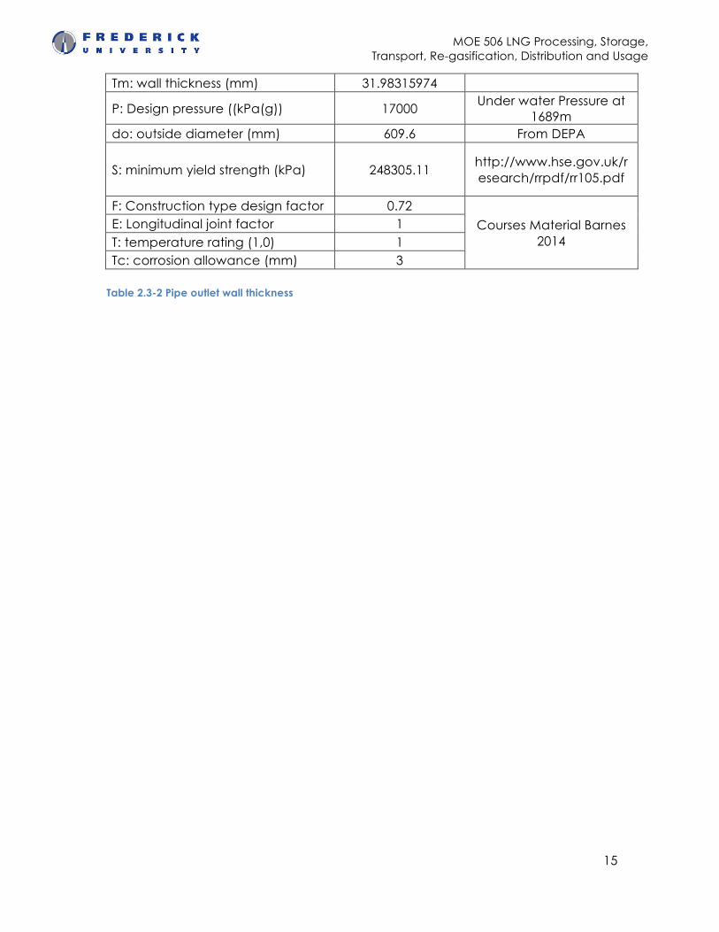
2.3.2 Wall thickness
The wall thickness is given from the following equation :
𝑇𝑚 =𝑃𝑑𝑜2𝑆𝐹𝐸𝑇
+ 𝑇𝑐
MOE 506 LNG Processing, Storage, Transport, Re-gasification, Distribution and Usage
15
Tm: wall thickness (mm) 31.98315974
P: Design pressure ((kPa(g)) 17000 Under water Pressure at
1689m do: outside diameter (mm) 609.6 From DEPA
S: minimum yield strength (kPa) 248305.11 http://www.hse.gov.uk/research/rrpdf/rr105.pdf
F: Construction type design factor 0.72
Courses Material Barnes 2014
E: Longitudinal joint factor 1 T: temperature rating (1,0) 1 Tc: corrosion allowance (mm) 3
Table 2.3-2 Pipe outlet wall thickness
MOE 506 LNG Processing, Storage, Transport, Re-gasification, Distribution and Usage
16
3. LNG export facilities and loading frequency
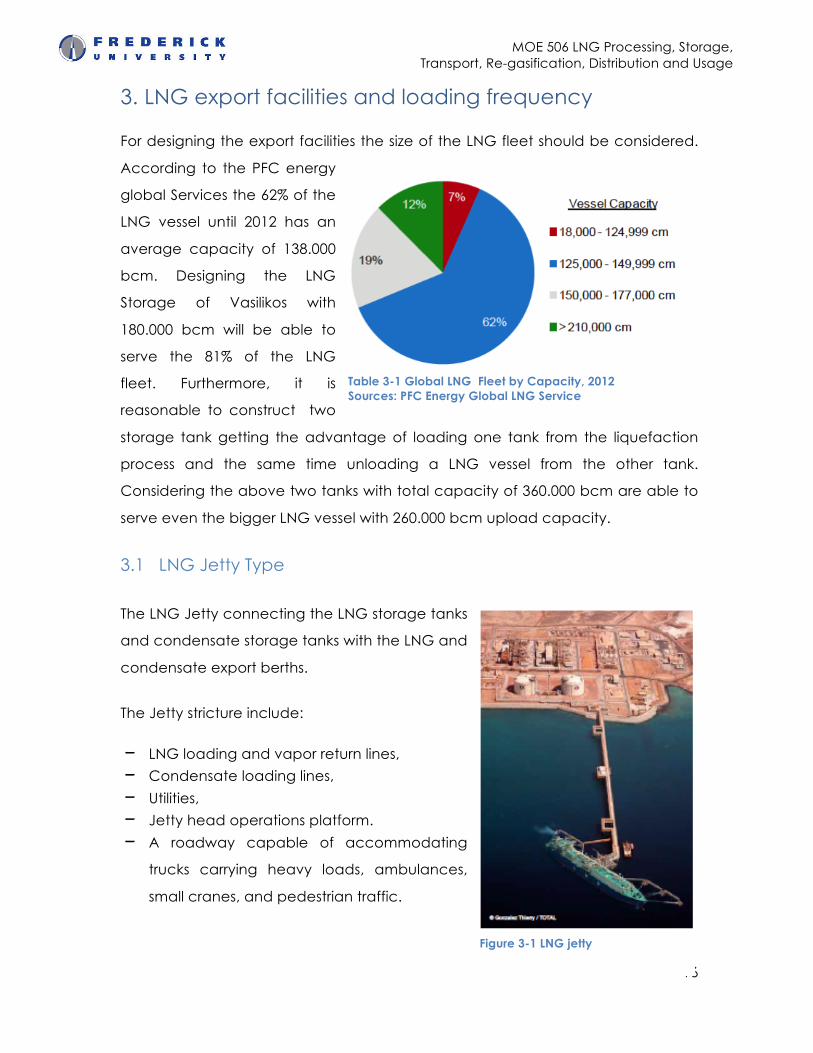
For designing the export facilities the size of the LNG fleet should be considered.
According to the PFC energy
global Services the 62% of the
LNG vessel until 2012 has an
average capacity of 138.000
bcm. Designing the LNG
Storage of Vasilikos with
180.000 bcm will be able to
serve the 81% of the LNG
fleet. Furthermore, it is
reasonable to construct two
storage tank getting the advantage of loading one tank from the liquefaction
process and the same time unloading a LNG vessel from the other tank.
Considering the above two tanks with total capacity of 360.000 bcm are able to
serve even the bigger LNG vessel with 260.000 bcm upload capacity.
3.1 LNG Jetty Type
The LNG Jetty connecting the LNG storage tanks
and condensate storage tanks with the LNG and
condensate export berths.
The Jetty stricture include:
− LNG loading and vapor return lines,
− Condensate loading lines,
− Utilities,
− Jetty head operations platform.
− A roadway capable of accommodating
trucks carrying heavy loads, ambulances,
small cranes, and pedestrian traffic.
Table 3-1 Global LNG Fleet by Capacity, 2012 Sources: PFC Energy Global LNG Service
Figure 3-1 LNG jetty
MOE 506 LNG Processing, Storage, Transport, Re-gasification, Distribution and Usage
17
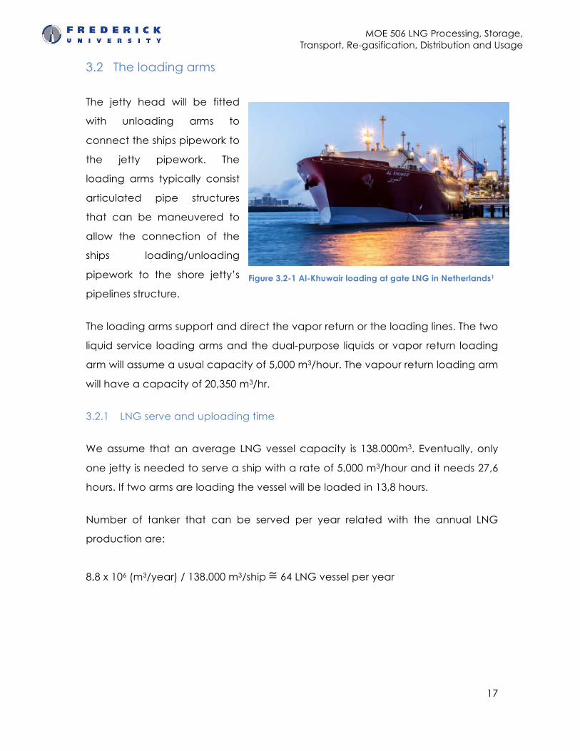
3.2 The loading arms
The jetty head will be fitted
with unloading arms to
connect the ships pipework to
the jetty pipework. The
loading arms typically consist
articulated pipe structures
that can be maneuvered to
allow the connection of the
ships loading/unloading
pipework to the shore jetty’s
pipelines structure.
The loading arms support and direct the vapor return or the loading lines. The two
liquid service loading arms and the dual-purpose liquids or vapor return loading
arm will assume a usual capacity of 5,000 m3/hour. The vapour return loading arm
will have a capacity of 20,350 m3/hr.
3.2.1 LNG serve and uploading time
We assume that an average LNG vessel capacity is 138.000m3. Eventually, only
one jetty is needed to serve a ship with a rate of 5,000 m3/hour and it needs 27,6
hours. If two arms are loading the vessel will be loaded in 13,8 hours.
Number of tanker that can be served per year related with the annual LNG
production are:
8,8 x 10⁶ (m3/year) / 138.000 m3/ship ≅ 64 LNG vessel per year
Figure 3.2-1 Al-Khuwair loading at gate LNG in Netherlands1
MOE 506 LNG Processing, Storage, Transport, Re-gasification, Distribution and Usage
18
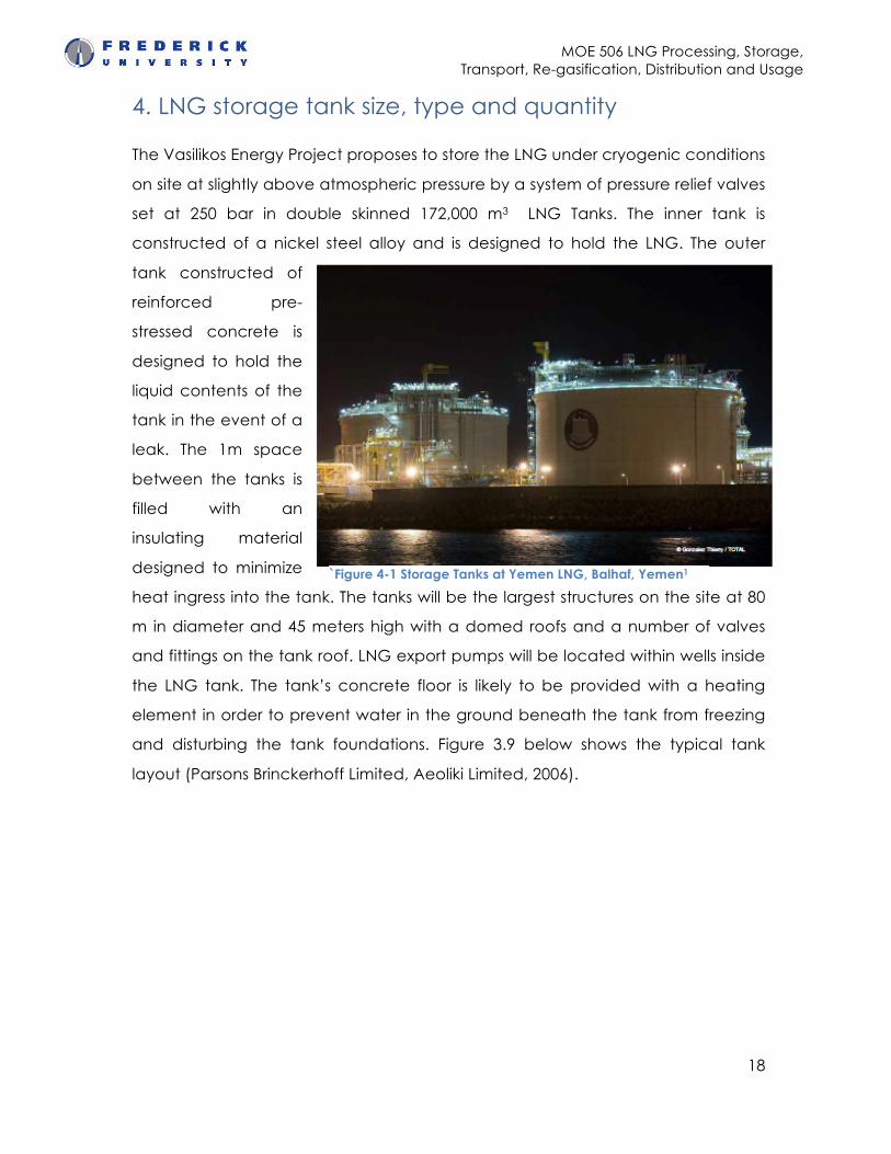
4. LNG storage tank size, type and quantity
The Vasilikos Energy Project proposes to store the LNG under cryogenic conditions
on site at slightly above atmospheric pressure by a system of pressure relief valves
set at 250 bar in double skinned 172,000 m3 LNG Tanks. The inner tank is
constructed of a nickel steel alloy and is designed to hold the LNG. The outer
tank constructed of
reinforced pre-
stressed concrete is
designed to hold the
liquid contents of the
tank in the event of a
leak. The 1m space
between the tanks is
filled with an
insulating material
designed to minimize
heat ingress into the tank. The tanks will be the largest structures on the site at 80
m in diameter and 45 meters high with a domed roofs and a number of valves
and fittings on the tank roof. LNG export pumps will be located within wells inside
the LNG tank. The tank’s concrete floor is likely to be provided with a heating
element in order to prevent water in the ground beneath the tank from freezing
and disturbing the tank foundations. Figure 3.9 below shows the typical tank
layout (Parsons Brinckerhoff Limited, Aeoliki Limited, 2006).
`Figure 4-1 Storage Tanks at Yemen LNG, Balhaf, Yemen1
MOE 506 LNG Processing, Storage, Transport, Re-gasification, Distribution and Usage
19
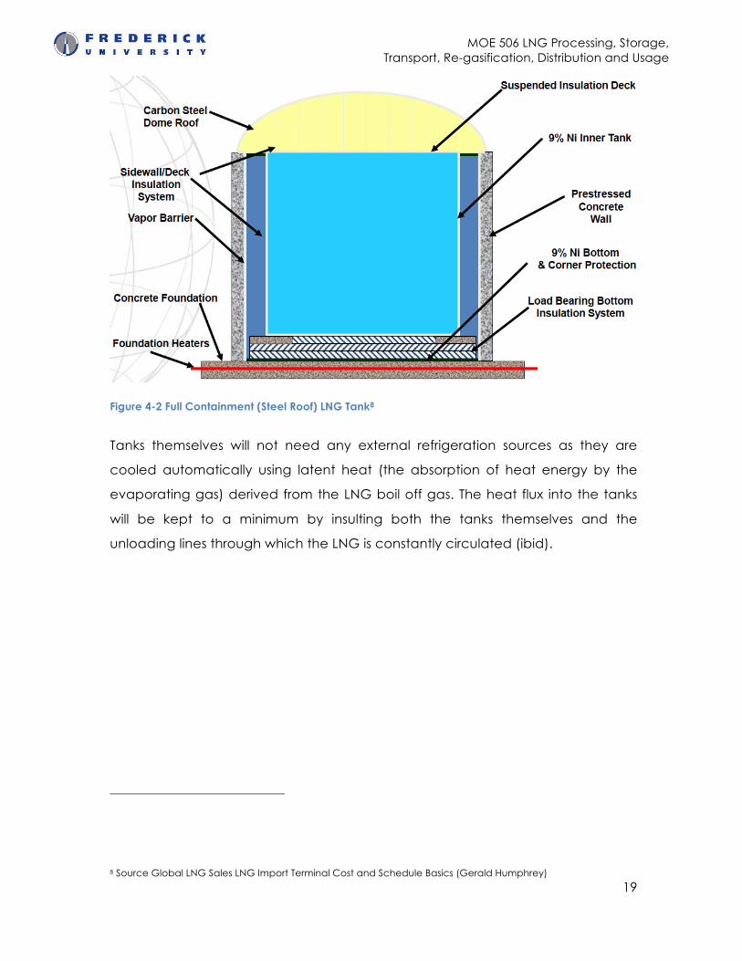
Figure 4-2 Full Containment (Steel Roof) LNG Tank8
Tanks themselves will not need any external refrigeration sources as they are
cooled automatically using latent heat (the absorption of heat energy by the
evaporating gas) derived from the LNG boil off gas. The heat flux into the tanks
will be kept to a minimum by insulting both the tanks themselves and the
unloading lines through which the LNG is constantly circulated (ibid).
8 Source Global LNG Sales LNG Import Terminal Cost and Schedule Basics (Gerald Humphrey)
MOE 506 LNG Processing, Storage, Transport, Re-gasification, Distribution and Usage
20
5. Bibliography
Unsupported source type (ElectronicSource) for source GUP.
Arms of innovation. 2014. [Film] France: dsp an endemol company.
BBCnews, 2013. "Shell's record-breaking Prelude takes to the water". [Online]
Available at:
https://web.archive.org/web/20131204184139/http://www.bbc.co.uk/news/tech
nology-25213845 [Accessed 04 December 2013].
Bergin, W. & Spearman, E., 2006. Vasilikos Energy Centre Basis of Design
Environmental Assessment. EA. Middlesex: Parsons Brinckerhoff Limited, Aeoliki
Limited.
Bp, 2013. con Fact. [Online] Available at: www.car.gr.
Briggs, et al., 2013. LNG LIQUEFACTION PLANT. In “Poten”, ed. MASTER PLAN OF
THE VASILIKOS AREA. NIcosia: “Poten” & "ALA". p.29.
Chartered , P., 1992. http://www.the-edi.co.uk/. [Online] (7th) Available at:
http://www.the-edi.co.uk/downloads/eia_spring_2007.pdf [Accessed 19 April
2007].
Exxon Mobil, 2013. [Online] Available at:
http://pnglng.com/downloads/eis_chapter04.pdf.
Delek Group, 2014. [Online] Available at:
http://www.google.com/url?sa=t&rct=j&q=&esrc=s&source=web&cd=1&ved=0C
CsQFjAA&url=http%3A%2F%2Fphx.corporate-
ir.net%2FExternal.File%3Fitem%3DUGFyZW50SUQ9NTM5MDYxfENoaWxkSUQ9MjI4NT
kzfFR5cGU9MQ%3D%3D%26t%3D1&ei=0lduU-
WqMsG1PcS0gMgD&usg=AFQjCNGDcT79dYdH6cavDiXX5Q2neeM4tQ&bvm=bv.
66330100,d.ZWU [Accessed April 2014].
MOE 506 LNG Processing, Storage, Transport, Re-gasification, Distribution and Usage
21
International Institute for Environment and Development (IIED) , n.d.
http://www.environmental-mainstreaming.org. [Online] Available at:
http://www.environmental-
mainstreaming.org/documents/EM%20Profile%20No%201%20-
%20EIA%20(6%20Oct%2009).pdf.
Kotzot, , Durr, , Coyle, & Caswell, , 2007. LNG LIQUEFACTION — NOT ALL PLANTS
ARE CREATED EQUAL. [Online] KBR Available at:
http://www.kbr.com/Newsroom/Publications/LNG/ [Accessed 2007].
National Centre for Risk Analysis and Options Appraisal Environment Agency,
2002. https://www.gov.uk/. [Online] Environment Agency Available at:
https://www.gov.uk/government/uploads/system/uploads/attachment_data/file
/296952/geho0411btrf-e-e.pdf [Accessed 01 May 2002]. A handbook for scoping
projects.
Nobole Energy International, 2013. http://www.mcit.gov.cy. [Online] Available at:
http://www.mcit.gov.cy/mcit/mcit.nsf/All/11FFCD876C06B58CC2257C7700255D1
8/$file/04-Vasilikos%20Master%20Plan%202013_Executive%20Summary%20-
%20Eng.pdf [Accessed 1 Octomber 2013].
Managment, E.R., 2001. http://ec.europa.eu/. [Online] Available at:
http://ec.europa.eu/environment/eia/eia-guidelines/g-scoping-full-text.pdf
[Accessed 19 April 2014].
Paltsev, et al., 2013. Natural Gas Monetization Pathways for Cyprus. Economics of
Project Development Options. Massachusetts: Massachusetts Institute of
Technology MIT Energy Initiative, Massachusetts Institute of Technology, Cyprus
Institute.
Parsons Brinckerhoff Limited, Aeoliki Limited, 2006. VASILIKOS ENERGY CENTRE
BASIS OF DESIGN ENVIRONMENTAL ASSESSMENT. Middlesex: M.W. Kellogg Limited
Kellogg.
MOE 506 LNG Processing, Storage, Transport, Re-gasification, Distribution and Usage
22
Shell, 2010. Transporting Oil and Gas, What’s in a Barrel of Oil?. [Online] Available
at: www.shell.us/alaska.
Shell, n.d. Prelude FLNG. [Online] Available at:
http://www.shell.com.au/aboutshell/who-we-are/shell-
au/operations/upstream/prelude.html [Accessed 2 May 2014].
Tsakiris, D.T., 2013. www.eliamep.gr/en. [Online] Available at:
http://www.eliamep.gr/wp-content/uploads/2014/02/policy-paper.pdf
[Accessed November 2013].
iSource about Shoviet reserve http://www.ivt.ntnu.no/ept/fag/tep4215/innhold/LNG%20Conferences/2007/fscommand/PS7_3_Skjerven_s.pdf