Embed Size (px)
Citation preview

PNNL-13786
Assessment of K Basin Sludge Volume Expansion Resulting from Uranium Corrosion During Storage A.J. Schmidt C.H. Delegard January 2002 Prepared for the U.S. Department of Energy under Contract DE-AC06-76RL01830

DISCLAIMER
This report was prepared as an account of work sponsored by an agency of the United States Government. Neither the United States Government nor any agency thereof, nor Battelle Memorial Institute, nor any of their employees, makes any warranty, express or implied, or assumes any legal liability or responsibility for the accuracy, completeness, or usefulness of any information, apparatus, product, or process disclosed, or represents that its use would not infringe privately owned rights. Reference herein to any specific commercial product, process, or service by trade name, trademark, manufacturer, or otherwise does not necessarily constitute or imply its endorsement, recommendation, or favoring by the United States Government or any agency thereof, or Battelle Memorial Institute. The views and opinions of authors expressed herein do not necessarily state or reflect those of the United States Government or any agency thereof.
PACIFIC NORTHWEST NATIONAL LABORATORY operated by BATTELLE
for the UNITED STATES DEPARTMENT OF ENERGY
under Contract DE-AC06-76RL01830
Printed in the United States of America
Available to DOE and DOE contractors from the Office of Scientific and Technical Information,
P.O. Box 62, Oak Ridge, TN 37831-0062; ph: (865) 576-8401 fax: (865) 576-5728
email: [email protected]
Available to the public from the National Technical Information Service, U.S. Department of Commerce, 5285 Port Royal Rd., Springfield, VA 22161
ph: (800) 553-6847 fax: (703) 605-6900
email: [email protected] online ordering: http://www.ntis.gov/ordering.htm
This document was printed on recycled paper. (8/00)

PNNL-13786
Assessment of K Basin Sludge Volume Expansion Resulting from Uranium Corrosion During Storage A. J. Schmidt C. H. Delegard January 2002 Prepared for the U.S. Department of Energy under Contract DE-AC06-76RL01830 and the Hanford Spent Nuclear Fuel Project Managed by Fluor Hanford, Inc. Pacific Northwest National Laboratory Richland, Washington 99352

Summary and Conclusions Two water-filled concrete pools [K East (KE) and K West (KW) Basins] in the 100K Area of the Hanford Site contain approximately 52 m3 of heterogeneous solid material (sludge). The baseline sludge manage-ment plan calls for it to be packaged, shipped, and stored at T Plant in the Hanford 200 Area until final processing at a future date. K Basin sludge contains metallic uranium and uranium oxides that will corrode and hydrate during storage. The end-state (final) corrosion products will have a lower particle density and a higher void fraction (or volume fraction of sludge occupied by water) than the starting-state sludge at the beginning of storage. As the particle density and void fraction change, the volume occupied by a given mass of sludge will also change. The purpose of this report is to quantify how the various types and sources of K Basin sludge will react and volumetrically expand between the time the sludge is first loaded into the storage containers (starting state) and the time all major volume-changing reactions have been completed (end state). The results from this report will be used in design and safety basis calculations for sludge management systems and will be incorporated into the sludge technical basis documents. Another mechanism for sludge volume expansion during storage is gas retention. Gas bubbles from chemical reactions and radiolysis can potentially become trapped in the sludge and increase the sludge volume. Sludge volume expansion by gas retention will be addressed in another report. However, the effects of sludge expansion due to both uranium corrosion and gas retention will need to be considered when establishing the final container loading parameters. Overview In this report, two sludge storage environments have been evaluated: 1) large container storage with passive venting (oxic) and 2) small container storage with a check valve (oxygen free or anoxic). The distinction of the storage environments is important, because the presence or absence of oxygen will determine the probable chemical reactions and the end-state uranium species generated. The sludge expansion calculations are based on assumed starting-state compositions for the uranium species, assumed controlling chemical reactions, and assumed ending-state compositions. In turn, the chemistry assumptions are based on the technical literature and results from X-ray diffraction analysis of K Basin sludge samples. The expected end-state compositions of the uranium corrosion products are used for most of the calculations. Also evaluated was a case in which the uranium was assumed to react to achieve maximum oxidation and hydration. This case was evaluated to provide a theoretical worst-case sludge expansion. This sludge expansion analysis covers a number of K Basin sludge types (fuel piece, KE canister, KW canister, KE floor, a 50/50 mix of fuel piece and KE canister sludge, and a 50/50 mix of KE canister and floor sludge), each with a different content and distribution of uranium species. For each type of sludge, the following factors have been derived for the applicable storage environments: 1) the expected volume
iii
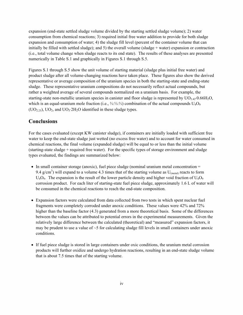
expansion (end-state settled sludge volume divided by the starting settled sludge volume); 2) water consumption from chemical reactions; 3) required initial free water addition to provide for both sludge expansion and consumption of water; 4) the sludge fill level (percent of the container volume that can initially be filled with settled sludge); and 5) the overall volume (sludge + water) expansion or contraction (i.e., total volume change when sludge reacts to its end state). The results of these analyses are presented numerically in Table S.1 and graphically in Figures S.1 through S.5. Figures S.1 through S.5 show the unit volume of starting material (sludge plus initial free water) and product sludge after all volume-changing reactions have taken place. These figures also show the derived representative or average composition of the uranium species in both the starting-state and ending-state sludge. These representative uranium compositions do not necessarily reflect actual compounds, but rather a weighted average of several compounds normalized on a uranium basis. For example, the starting-state non-metallic uranium species in canister and floor sludge is represented by UO2.42⋅0.66H2O, which is an equal-uranium mole fraction (i.e., ⅓:⅓:⅓) combination of the actual compounds U4O9 (UO2.25), UO2, and UO3⋅2H2O identified in these sludge types. Conclusions For the cases evaluated (except KW canister sludge), if containers are initially loaded with sufficient free water to keep the end-state sludge just wetted (no excess free water) and to account for water consumed in chemical reactions, the final volume (expanded sludge) will be equal to or less than the initial volume (starting-state sludge + required free water). For the specific types of storage environment and sludge types evaluated, the findings are summarized below:
• In small container storage (anoxic), fuel piece sludge (nominal uranium metal concentration = 9.4 g/cm3) will expand to a volume 4.3 times that of the starting volume as U(metal) reacts to form U4O9. The expansion is the result of the lower particle density and higher void fraction of U4O9 corrosion product. For each liter of starting-state fuel piece sludge, approximately 1.6 L of water will be consumed in the chemical reactions to reach the end-state composition.
• Expansion factors were calculated from data collected from two tests in which spent nuclear fuel
fragments were completely corroded under anoxic conditions. These values were 42% and 72% higher than the baseline factor (4.3) generated from a more theoretical basis. Some of the differences between the values can be attributed to potential errors in the experimental measurements. Given the relatively large difference between the calculated (theoretical) and “measured” expansion factors, it may be prudent to use a value of ~5 for calculating sludge fill levels in small containers under anoxic conditions.
• If fuel piece sludge is stored in large containers under oxic conditions, the uranium metal corrosion
products will further oxidize and undergo hydration reactions, resulting in an end-state sludge volume that is about 7.5 times that of the starting volume.
iv

• KE canister sludge, with a safety basis U(metal) concentration of 1.5 g/cm3, will expand by 40% in large container oxic storage and by about 20% in anoxic storage. KW canister sludge will expand to about 1.7 times that of the starting volume under anoxic storage.
• Because of the relatively low uranium content and the starting-state oxidized condition of KE floor
sludge, expansion during storage is expected to be small, about 4%.
• The sludge collected in the knockout pot, which will be loaded into the small containers, is expected to resemble a 50/50 (vol/vol) mixture of KE fuel piece sludge and KE canister sludge. This 50/50 mixture, under anoxic storage, is expected to expand to 2.8 times that of its initial volume.
• Some sludge loaded into large containers may be a 50/50 (vol/vol) mixture of KE canister and floor
sludge. This 50/50 mixture, under oxic storage, is expected to expand to 1.22 times that of its initial volume. For this case, assuming all required water is added to the starting-state sludge, the sludge loading would be limited to about 81% (volume) of the container volume.
• Under worst-case expansion conditions for fuel piece sludge [oxic storage, complete conversion of
U(metal) to studtite (UO4·4H2O)] the end-state sludge volume would be 11.9 times that of the starting-state sludge. To provide sufficient water to account for the water consumed in the chemical reactions and to maintain the expanded sludge in a just wetted state (no excess free water), 13.5 L of water would be required for each liter of starting-state fuel piece sludge. For this case, assuming all required water is initially added to the starting-state fuel piece sludge, the sludge loading would be limited to about 6.9% of the container volume.
The evaluation of sludge expansion resulting from the corrosion of uranium species examines only one of several factors that will constrain the amount of sludge and water than can be loaded into a storage container. Other factors that will affect storage container loading include gas retention within the sludge as uranium oxidizes, vessel spanning bubble formation, allocation of a water layer to maintain wet sludge over the storage period (and the corresponding water evaporation rate), and head space (i.e., open space gas region) requirements. All of these factors will need to be considered when establishing the final container loading parameters.
v

Table S.1. Summary of Expansion Factors, Water Consumption, and Initial Container Fill Levels for Large and Small Container Storage Environments
Sludge Expansion Factor(a) (volume
final/volume initial)
Water Consumption(b) (g per liter initial
sludge)
Required Free Water(c)
(L water per L initial sludge)
Sludge Fill Level(d) (% of initial volume occupied by sludge)
Total Volume Change, %(e) Storage Container
Type Large Small Large Small Large Small Large Small Large SmallFuel Piece Sludge 7.5 4.3
5.2(f) 2310 1600
1600(f) 7.52 4.44
5.09(f) 12 18
16(f) –12 –21
–15(f) KE Canister Sludge 1.4 1.2 67 30 0.42 0.23 70 81 –1.4 –2.4 KW Canister Sludge NA 1.7 NA 49 NA 0.62 NA 62 +4.9 KE Floor Sludge 1.04 NA 8.9 NA 0.05 NA 95 NA –1.2 NA 50/50 Volume Fuel Piece/Canister Sludge Mix
NA 2.83.2(f)
NA 815815(f)
NA 2.342.66(f)
NA 3027(f)
NA –18 –13(f)
50/50 Volume KE Canister/Floor Sludge Mix
1.22 NA 37.8 NA 0.24 NA 81 NA –1.6 NA
Fuel Piece Sludge; Worst-Case Expansion
11.9 NA 4980 NA 13.5 NA 6.9 NA –18 NA
(a) Final volume of end-state settled sludge (assuming sufficient initial free water to keep the sludge wetted) divided by the volume of starting-state settled sludge.
(b) Water consumed in uranium metal and uranium oxide corrosion and hydration reactions. (c) Free water needed to allow expanded sludge to stay wetted and to account for water consumed by chemical reactions. (d) Assuming a container is filled 100% with water and starting-state sludge, this column gives the maximum sludge fill level. These fill levels do not
account for evaporation of water during storage or any volume for vapor space. (e) Total volume change = 100 x [1 – (final total volume after full expansion)/(volume initial sludge + volume required free water)]. (f) These values are based on an expansion factor of 5.2 for fuel piece sludge under anoxic conditions. The factor of 5.2 is more consistent with
experimentally measured expansion factors (Gas Generation Testing Series III) than the baseline 4.3 value.
vi

Fuel Piece
0
0.2
0.4
0.6
0.8
1
Initial Volume Final Volume Initial Volume Final Volume
Large - Oxic Small - Anoxic
Frac
tion
Leve
l
Final Settled Sludge;U as UO2.63
.H2OU Fuel Piece Sludge
Final Settled Sludge;U as UO2.25
Initial Free WaterInitial Free Water
U Fuel Piece Sludge
Figure S.1. Starting-State (Initial) and Ending-State (Final) Fuel Piece Sludge Volumes Under Oxic and Anoxic Storage Conditions
KE Canister Sludge
0
0.2
0.4
0.6
0.8
1
Initial Volume Final Volume Initial Volume Final Volume
Large - Oxic Small - Anoxic
Frac
tion
Leve
l
Final Settled Sludge;U as UO2.5
.0.66H2OFinal Settled Sludge;U as UO2.63
.H2O
Initial Free Water
Initial Free Water
KE Canister Sludge;U as U Metal and
UO2.42.0.66H2O
KE Canister Sludge;U as U Metal and
UO2.42.0.66H2O
Figure S.2. Starting-State (Initial) and Ending-State (Final) KE Canister Sludge Volumes Under Oxic and Anoxic Storage Conditions
vii

KW Canister Sludge
0
0.2
0.4
0.6
0.8
1
Initial Volume Final Volume Initial Volume Final Volume
Large - Oxic Small - Anoxic
Frac
tion
Leve
l
NotApplicable
Initial Free Water
KW Canister Sludge;U as U Metal and
UO2.42.0.66H2O
Final Settled Sludge;U as UO2.5
.0.66H2O
Figure S.3. Starting-State (Initial) and Ending-State (Final) KW Canister Sludge Volumes Under Anoxic Storage Conditions
KE Floor Sludge
0
0.2
0.4
0.6
0.8
1
Initial Volume Final Volume Initial Volume Final Volume
Large - Oxic Small - Anoxic
Frac
tion
Leve
l
KE Floor Sludge;U as U Metal and
UO2.42.0.66H2O
50-50 Fuel -KE Canister Sludge;
U as U Metal andUO2.42
.0.66H2O
Initial Free Water
Initial Free Water
Final Settled Sludge;U as UO2.25 andUO2.5
.0.66H2O
Final Settled Sludge;U as UO2.63
.H2O
50-50 Fuel Piece - Canister Sludge
Figure S.4. Starting-State (Initial) and Ending-State (Final) KE Floor Sludge Volumes Under Oxic Storage Conditions and 50/50 Fuel Piece/Canister Sludge Volumes Under Anoxic Storage Conditions
viii

Fuel Piece Sludge - Worst Case
0
0.2
0.4
0.6
0.8
1
Initial Volume Final Volume Initial Volume Final Volume
Large - Oxic Large - Oxic
Frac
tion
Leve
l
Final Settled Sludge;U as UO4
.4H2O
50-50 KE Canister : Floor Sludge Mix
Final Settled Sludge;U as UO2.63
.H2O
50-50 KE Floor-Canister Sludge;
U as UO2.42.0.66H2O
Initial Free Water
Initial Free Water
U Fuel Piece Sludge
Figure S.5. Starting-State (Initial) and Ending-State (Final) 50/50 KE Canister/Floor Sludge Volumes Under Oxic Storage Conditions and Fuel Piece Sludge Volumes Under Worst-Case Oxic Storage Conditions
ix

Contents Summary and Conclusions ................................................................................................................... iii 1.0 Introduction.................................................................................................................................... 1.1 2.0 Data and Assumptions ................................................................................................................... 2.1 2.1 Uranium Oxidation/Hydration Chemistry .............................................................................. 2.3 2.2 Assumed Controlling Chemistry and End State of Reacted Fuel Pieces ................................ 2.4 2.2.1 End State of Reacted Uranium Pieces in Large Containers .......................................... 2.4 2.2.2 End State of Reacted Uranium Pieces in Small Containers .......................................... 2.5 2.3 Assumed Controlling Chemistry of Non-Metallic Uranium................................................... 2.6 2.3.1 Starting State of Non-Metallic Uranium in K Basin Sludge......................................... 2.6 2.3.2 End State of Non-Metallic Uranium in Large Containers ............................................ 2.6 2.3.3 End State of Non-Metallic Uranium in Small Containers ............................................ 2.6
2.4 Void Volume and Settled Sludge Density of Fuel Piece Sludge and 100% Non-Metallic Uranium Sludge ...................................................................................................................... 2.7
2.5 Summary of Assumed Chemistry and Parameters Used in Sludge Expansion Factor Calculation................................................................................................................... 2.8 3.0 Sludge Expansion Determinations ................................................................................................. 3.1 3.1 Metallic Fuel Pieces................................................................................................................ 3.1 3.1.1 Large Container Storage – Oxic Conditions ................................................................. 3.1 3.1.2 Small Container Storage – Anoxic Conditions ............................................................. 3.3 3.2 KE Canister Sludge................................................................................................................. 3.8 3.2.1 Large Container Storage – Oxic Conditions ................................................................. 3.9
xi
3.2.2 Small Container Storage – Anoxic Conditions ............................................................. 3.11 3.3 KW Canister Sludge ............................................................................................................... 3.13 3.3.1 Sludge Volume Expansion Factor (Small Container Storage – Anoxic Conditions) ... 3.14 3.3.2 Total Volume Expansion for KW Canister Sludge....................................................... 3.14
3.4 KE Floor Sludge ..................................................................................................................... 3.15 3.4.1 Crosscheck on Validity of Floor Sludge Starting State ................................................ 3.16 3.4.2 Sludge Volume Expansion Factor for Floor Sludge in Large Container Storage......... 3.17 3.4.3 Total Volume Expansion for KE Floor Sludge............................................................. 3.17
3.5 50/50 Volume Mixture of Fuel Piece Sludge and KE Canister Sludge in Small Containers..................................................................................................................... 3.18
3.5.1 Sludge Volume Expansion Factor for 50/50 Mix in Small Containers ........................ 3.18 3.5.2 Total Volume of Expanded Sludge............................................................................... 3.19 3.6 50/50 Volume Mixture of KE Canister and KE Floor Sludge in Large Containers ............... 3.19 3.6.1 Sludge Volume Expansion Factor for 50/50 Mix in Large Containers......................... 3.19 3.6.2 Total Volume of Expanded Sludge............................................................................... 3.19 4.0 Worst-Case Expansion of Fuel Piece Sludge (Oxic Storage Conditions)...................................... 4.1 4.1 Expansion of Fuel Piece Sludge to Form Meta Schoepite (UO3·2H2O) ................................. 4.1 4.1.1 Controlling Chemistry: ................................................................................................. 4.1 4.1.2 Sludge Volume Expansion Factor................................................................................. 4.2 4.1.3 Total Volume Expansion .............................................................................................. 4.2 4.2 Expansion of Fuel Piece Sludge to Form Studtite (UO4·4H2O).............................................. 4.3 4.2.1 Controlling Chemistry .................................................................................................. 4.3
xii

4.2.2 Sludge Volume Expansion Factor................................................................................. 4.4 4.2.3 Total Volume Expansion .............................................................................................. 4.5 5.0 References...................................................................................................................................... 5.1
xiii
Figures S.1 Starting-State (Initial) and Ending-State (Final) Fuel Piece Sludge Volumes Under Oxic and Anoxic Storage Conditions ................................................................................ vii S.2 Starting-State (Initial) and Ending-State (Final) KE Canister Sludge Volumes Under Oxic and Anoxic Storage Conditions ................................................................................ vii S.3 Starting-State (Initial) and Ending-State (Final) KW Canister Sludge Volumes Under Anoxic Storage Conditions ................................................................................................ viii S.4 Starting-State (Initial) and Ending-State (Final) KE Floor Sludge Volumes Under Oxic Storage Conditions and 50/50 Fuel Piece/Canister Sludge Volumes Under Anoxic Storage Conditions........................................................................................................... viii S.5 Starting-State (Initial) and Ending-State (Final) 50/50 KE Canister/Floor Sludge Volumes Under Oxic Storage Conditions and Fuel Piece Sludge Volumes Under Worst-Case Oxic Storage Conditions........................................................................................................................ ix
Tables S.1 Summary of Expansion Factors, Water Consumption, and Initial Container Fill Levels for Large and Small Container Storage Environments ................................................................. vi 2.1 Particle Densities of Potential and Observed Crystalline Uranium Compounds in K Basin Sludge ........................................................................................................................................... 2.1 2.2 Total Uranium, Particle Densities, Settled Sludge Densities, and Identified Uranium Phases for Selected High-Uranium-Content K Basin Sludge Samples and Fuel Fragments.................... 2.2 2.3 Summary of Assumed Chemistry and Physical Properties for Metallic Uranium Fuel Pieces in Large (Oxic) and Small (Anoxic) Storage Containers .......................................... 2.8 2.4 Summary of Assumed Chemistry and Physical Properties of Non-Metallic Uranium in Large (Oxic) and Small (Anoxic) Storage Containers............................................... 2.9 3.1 Test Data from Gas Generation Series III Tests Mid 80 and M500 ............................................. 3.6
xiv

1.0 Introduction Two water-filled concrete pools [K East (KE) and K West (KW) Basins] in the 100K Area of the Hanford Site contain over 2100 metric tons of N Reactor fuel elements stored in aluminum or stainless steel canisters. During the time the fuel has been stored, approximately 52 m3 of heterogeneous solid material (sludge) have accumulated in the canisters, as well as on the floor and in the associated pits. This sludge consists of various proportions of fuel; structural corrosion products; windblown material; and miscellaneous constituents, such as ion exchange material (both organic and inorganic) and paint chips (Makenas et al. 1996-99). Pearce (2001) describes the inventory and compositions of all K Basin sludge materials in detail. The baseline sludge management plan calls for the sludge to be packaged, shipped, and stored at T Plant in the Hanford 200 Area until final processing at a future date. K Basin sludge contains metallic uranium and uranium oxides that will corrode and hydrate during storage. The end-state corrosion products will have a lower particle density and a higher void fraction (or volume fraction of sludge occupied by water) than the starting-state sludge at the beginning of storage. As the particle density and void fraction change, the volume occupied by a given mass of sludge will also change. This report presents calculations performed by Pacific Northwest National Laboratory (PNNL) (under contract to the Fluor Hanford Spent Nuclear Fuel Project) to quantify how the various types and sources of K Basin sludge will react and volumetrically expand between the time the sludge is first loaded into the storage containers (starting state) and the time all major volume-changing reactions have been completed (end state). The results from this report will be used in design and safety basis calculations for sludge management systems and will be incorporated into a future revision of the sludge technical basis document (Plys and Pearce 2001). Additional support for this report was provided by the Fluor Hanford Technology Management Office. The calculations given here are based on assumed starting-state compositions for the uranium species, assumed controlling chemical reactions, and assumed ending-state compositions. Where possible, safety basis values for key parameters (e.g., uranium metal content) have been used. The controlling chemistry assumptions are based on the technical literature and results from X-ray diffraction (XRD) analysis of K Basin sludge samples. Where actual data exist, crosscheck calculations have been included to validate assumptions. Two sludge storage environments have been evaluated: 1) large container storage with passive venting to the atmosphere (oxic); and 2) small container storage with a check valve (oxygen free or anoxic). The distinction of the storage environments is important, because the presence or absence of oxygen will determine the probable chemical reactions and the end-state uranium species generated. The large containers (approximately 5 ft in diameter and 10 ft high) will be used primarily for floor, pit, and canister sludge and will be stored in air in process cells at T Plant. Each large container will include at least one passive filter vent. Through diffusion and barometric pressure changes, oxygen (from air) will enter the storage containers and dissolve into the sludge and water. Therefore, to some extent, dissolved oxygen will be available for the corrosion of uranium metal and further oxidation of the various species of uranium.
1.1

High-uranium-content sludge (fuel piece and canister sludge) will be stored in small containers (nominally, less than 2 ft in diameter). To maintain thermal stability, the small containers will be stored underwater in the T Plant fuel pool. While the small containers will be vented to allow generated offgas to escape, the vent system will include a check valve to prevent backflow of gas or water. It is presumed that the head space of the small containers will be purged with an inert gas before the containers are transported to T Plant. Consequently, the sludge in the small containers will corrode in an environment free of oxygen (anoxic). This report provides a quantitative evaluation of the sludge expansion for a number of the K Basin sludge types in two different storage environments. Section 2.0 provides data on the uranium compounds found in the sludge and the physical properties of high-uranium-content sludge samples, and develops the chemistry and physical property assumptions. Section 3.0 contains the sludge expansion evaluations based on the most probable corrosion chemistry. Section 4.0 is a worst-case expansion evaluation for fuel piece sludge based on the theoretical maximum uranium oxidation and hydration.
1.2

2.0 Data and Assumptions The underlying data and the chemistry used to develop the sludge expansion factors for each sludge type are discussed in this section, along with the rationale for each assumption used in this evaluation. The chemistry assumptions are derived in part from the K Basin sludge XRD data. Several limitations are associated with the XRD that could affect the chemistry assumptions. For example, XRD is semi-quantitative; therefore, the assignments on the masses of the uranium species in the expansion factor evaluation are somewhat speculative. Also, since XRD only detects crystalline compounds, the presence and potential impacts of amorphous materials are unknown. Finally, during the K Basin sludge characterization campaigns, several unknown compounds were consistently detected by XRD. These unknowns could have been additional uranium phases. Table 2.1 lists most of the uranium phases detected in K Basin sludge samples and provides particle density data. Table 2.2 includes characterization information (weight fraction uranium, dry particle density, settled density) on K Basin sludge samples that contain high concentrations of uranium. Where data exist, uranium phases detected via XRD are listed. To crosscheck the calculated factor for fuel piece sludge, the observed expansion factors from the Gas Generation Series III Tests [Silvers, K. L. August 3, 2001. “Preliminary Results from Gas Generation Series III Testing.” Letter to W. W. Rutherford, Fluor Hanford. 43610-L01, Pacific Northwest National Laboratory, Richland, Washington] have been examined. The Series III tests were performed for the Hanford Spent Nuclear Fuel (SNF) Project by PNNL to examine the chemical reaction and gas generation
Table 2.1. Particle Densities of Potential and Observed Crystalline Uranium Compounds in K Basin Sludge (Makenas et al. 1996-1999; Delegard et al. 2000; Pearce 2001)
Compound Chemical Formula Theoretical Particle Density, g/cm3 Uranium Metal U(metal) 19.0 Uraninite UO2 10.95 Uraninite U4O9 (UO2.25) 11.30 Uraninite U3O7 11.32 Triuranium Octoxide U3O8 8.3 Schoepite UO3⋅2.25H2O 4.87 Metaschoepite UO3⋅2H2O 4.87 Paraschoepite UO2.86⋅1.5H2O 6.85 Studtite UO4⋅4H2O 5.15 Uranium Hydride UH3 11.12 Sodium Uranium Hydroxide Hydrate Na2(UO2)6(OH)14⋅4H2O ~5 Sodium Uranium Oxide Hydrate Na2U2O7⋅6H2O ~5 Calcium Uranate CaU6O19⋅12H2O ~5 Potassium Uranate K2UO4 ~5
2.1

Table 2.2. Total Uranium, Particle Densities, Settled Sludge Densities, and Identified Uranium Phases for Selected High-Uranium-Content K Basin Sludge Samples and Fuel Fragments
Sample Name and Description
Total Uranium,
wt%, dry basis
Dry Particle Density,
g/cm3
As-Settled Solids Density (Wet), g/cm3
U Crystalline and Other Phases Identified via XRD
KE Canister Sludge, 1996 Sample Campaign (Makenas et al. 1997) 96-01 82 NM 2.09 UO2, U4O9, U3O7 96-04-L (Lower layer of sludge, ~55 wt% of whole sample)
54 4.76 1.46 UO2, U4O9, U3O7, UO3⋅2H2O
96-05 88 NM 2.62 UO2, U4O9, U3O7, UO3⋅2H2O 96-06-M (Middle layer, ~20 wt% of whole sample) 83 6.90 1.92 UO2, U4O9, U3O7 96-06-L (Lower layer of sludge, ~52 wt% of whole sample)
84 7.88 2.99 UO2, U4O9, U3O7
96-13 82 NM 2.46 UO2, U4O9, U3O7 96-15 81 NM 1.84 UO2, U4O9, U3O7
K West Canister Sludge (Makenas et al. 1998) 96-21A (particles 710 to 6350 µm, 3 vol% of total sample)
NM 14.85 NM U4O9, UO3⋅2H2O, Carbon
96-21Rec (particles < 710 µm, 97 vol% of total sample)
80 7.41 3.55 to 4.18 U4O9, UO3⋅2H2O
96-23-6 (particles 3350 to 6350 µm, 7 vol% of total sample)
NM 2.26 NM Graphite
96-23-A (particles 710 to 3350 µm, 13 vol% of total sample)
NM 2.72 NM Mostly Carbon (graphite), U4O9
96-24-6 (particles 3350 to 6350 µm, 13 vol% of total sample)
NM 2.54 NM Mostly Carbon (graphite), U4O9
96-24-A (particles 710 to 3350 µm, 3 vol% of total sample)
NM 4.71 NM Carbon (graphite) U4O9,
UO3⋅2H2O 96-24Rec (particles < 710 µm, 84 vol% of total sample)
54 8.11 2.64 U4O9, UO2.86⋅1.5H2O
96-16 81 NM 3.83 NM 96-17 94 NM 3.56 NM
Residual Sludge (Dislodged from fuel elements during shipping from Basins) (Makenas et al. 1999) R1-Rec (particles < 250 µm, 51.3 wt% of total sample) 68 7.16 NM U4O9, UO3⋅2H2O R5-Rec (particles < 500 µm, 100 wt% of total sample) 63 7.46 NM U4O9, UO3⋅2H2O
KE Consolidated Sludges (Bredt et al. 1999; Delegard et al. 2000; Elmore et al. 2000) KC-2/3 M250 (KE canister sludge composite particles < 250 µm, ~75 wt% of sample)
68 7.57 2.13 U4O9, UO3⋅2H2O
KC-2/3 (250 to 500 µm particles, ~16 wt% of total sample)
NM 6.91 NM U4O9, UO3⋅2H2O
KC-2/3 P250 (KE canister sludge particles 250 µm to 6350 µm, ~25 wt% of sample
35.2 2.23-6.91 2.11 U4O9, UO3 2H2O
KC-5 M250 (KE Floor sludge particles < 250 µm, 40 to 60 wt% of sample)
6.4 3.14 1.19 UO3⋅2H2O
Gas Generation III Fuel Fragments(a)
SNF Mid 80 (particles < 500 µm created by reacting 500 to 2000 µm uranium metal fragments to point of no hydrogen generation)
~100 9.4 2.75 U4O9, UO2
SNF M500 (particles < 250 µm after reacting 0 to 500 µm uranium fragments to the point of no further hydrogen generation)
~100 8.9 2.35 U4O9, UO2
NM = not measured. (a) Silvers, K. L. August 3, 2001. “Preliminary Results from Gas Generation Series III Testing.” Letter to W. W. Rutherford, Fluor
Hanford. 43610-L01, Pacific Northwest National Laboratory, Richland, Washington.
2.2

behavior of irradiated SNF fragments typical of those expected from elements stored at the K Basins. Portions of the fuel pieces were crushed and fractionated by particle size using wire mesh sieves. The fractionated and unfractionated fuel fragments were tested with and without KE Basin sludge addition. From the measurement of the total gas generated, the initial quantity of uranium metal was determined. After the testing, the reaction vessels were disassembled; the resulting sludge was recovered; and measurements were made (settled density, fraction solids, and dry particle density). The data in Tables 2.1 and 2.2 were used to establish some of the physical properties of various sludge types used in the sludge expansion evaluation. Additionally, the data were used to validate and crosscheck general assumptions. 2.1 Uranium Oxidation/Hydration Chemistry Oxidation of uranium metal [U(metal)] occurs most rapidly in water by direct anoxic reaction with water to form UO2 and, at completion, UO2.25, as shown in Reactions 1 and 2: U(metal) + 2 H2O → UO2 + 2 H2 (1) U(metal) + 2.25 H2O → UO2.25 + 2.25H2 (2) Oxidation beyond UO2.25 requires oxygen to form schoepites (UO2.86⋅1.5H2O; UO3⋅2H2O) as shown in Reactions 3 and 4: UO2.25 + 0.305 O2 + 1.5 H2O → UO2.86⋅1.5H2O (3) UO2.25 + 0.375 O2 + 2 H2O → UO3⋅2H2O (4) The schoepites can undergo subsequent reactions to form other U(VI) phases (see Section 4.1). For example, a paragenetic sequence of mineralization is observed in an aerated reaction of unirradiated UO2 with simulated groundwater at 90°C (Wronkiewicz et al. 1996; note, the simulated groundwater used in the Wronkiewicz study is higher in dissolved minerals than the ion exchange-purified K Basin waters). In the published study, the UO2, in the form of a pressed and sintered fuel pellet, was observed to transform to UO2.25 and then to schoepite (UO3⋅2H2O; ρ=4.87 g/cm3; 322.1 g/mole), becquerelite (CaU6O19·11H2O; ρ=5.14 g/cm3; 1970.4 g/mole), and compreignacite [K2(UO2)6O4(OH)6(H2O)8] (at ~1 to 3 years), followed by soddyite [(UO2)2SiO4⋅2H2O; ~3 years; ρ=4.63 g/cm3; 668.17 g/mole], uranophane [CaUO2SiO3(OH)2⋅5H2O; ρ=3.90 g/cm3; 510.3 g/mole], and other alkali and alkaline earth uranyl silicates (after 4 to 7 years). Accompanying decreases in pH and alkali, alkaline earth, and silicon solution concentrations also were observed as the mineralization progressed. Similar, though likely much slower progression (because of lower temperatures and lower solute concentrations), would be expected for the K Basin sludge. Note that becquerelite [formed from
2.3

schoepite and the calcite, CaCO3 (ρ=2.71 g/cm3; 100.1 g/mole) present in the sludge by Reaction 5], as well as sodium and potassium uranates, has already been observed in some K Basin sludge samples (Delegard et al. 2000). 24 UO3⋅2H2O + 4 CaCO3 → 4 CaU6O19·11H2O + 4 H2O + 4 CO2↑ (5) 2.2 Assumed Controlling Chemistry and End State of Reacted Fuel Pieces The end state of uranium metal during storage will depend on the storage conditions. The sludge stored in large containers will have access to oxygen (from air), while the sludge stored in small containers (fuel piece sludge and canister sludge) will corrode under anoxic conditions. 2.2.1 End State of Reacted Uranium Pieces in Large Containers The sludge stored in the large containers will contain some dissolved oxygen, and a mechanism exists to replenish the oxygen as it is consumed. Therefore, to some extent, the available oxygen will allow uranium oxides to further oxidize and hydrate in accordance with Reaction 3 and 4. Complete conversion of all uranium in the large containers to UO2.86⋅1.5H2O and UO3⋅2H2O is not expected. The supply of oxygen to the sludge will be limited, as most gas will flow from inside the storage container to the T Plant ventilation system. Other non-uranium species in the sludge may also consume/bind with oxygen. Finally, as demonstrated in the Gas Generation Series III testing, the presence of a sludge layer slows down the rate at which uranium metal (and presumably, uranium oxides) react. It has been assumed that the end state for uranium metal corrosion in large containers is a 50/50 (U basis) combination of the products of Reactions 2 and 4 (i.e., the most frequently observed identifiable uranium compounds during XRD analysis). The combined equation (two times Reaction 2 + Reaction 4) is: 2 U(metal) + 0.375 O2 + 6.5 H2O → UO2.25 + UO3⋅2H2O + 4.5 H2 (6) or U(metal) + 0.188 O2 + 3.25 H2O → UO2.63⋅H2O + 2.25 H2 The “average” dry particle density of the uranium corrosion product mixture, UO2.25 + UO3⋅2H2O (or UO2.63⋅H2O) is calculated to be approximately 6.60 g/cm3.(a)
(a) Assuming 0.5 g U(metal) each to produce UO2.25 and UO3⋅2H2O,
33
2325.2
2325.2 cm/g60.6cm]139.0051.0[
g]676.0576.0[]OH2UOUO[Volume
]OH2UOUO[Massdensity =
+
+=
⋅+⋅+
=
2.4
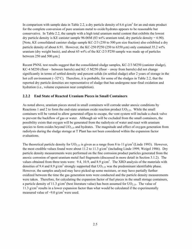
In comparison with sample data in Table 2.2, a dry particle density of 6.6 g/cm3 for an end-state product for the complete conversion of pure uranium metal to oxide/hydrates appears to be reasonable but conservative. In Table 2.2, the sample with a high total uranium metal content that exhibits the lowest dry particle density is KE canister sample 96-06M (83 wt% uranium total, dry particle density = 6.90). [Note, KE consolidated canister sludge sample KC-2/3 (250 to 500 µm size fraction) also exhibited a dry particle density of about 6.91. However, the KC-250 P250 (250 to 6350 µm) only contained 35.2 wt% uranium (dry weight basis), and about 65 wt% of the KC-2/3 P250 sample was made up of particles between 250 and 500 µm.] Recent PNNL test results suggest that the consolidated sludge samples, KC-2/3 M250 (canister sludge), KC-4 M250 (floor – between barrels) and KC-5 M250 (floor – away from barrels) did not change significantly in terms of settled density and percent solids (in settled sludge) after 2 years of storage in the hot cell environment (~32°C). Therefore, it is probable, for some of the sludges in Table 2.2, that the reported dry particle densities are representative of sludge that has undergone near-final oxidation and hydration (i.e., volume expansion near completion). 2.2.2 End State of Reacted Uranium Pieces in Small Containers As noted above, uranium pieces stored in small containers will corrode under anoxic conditions by Reactions 1 and 2 to form the end-state uranium oxide reaction product UO2.25. While the small containers will be vented to allow generated offgas to escape, the vent system will include a check valve to prevent the backflow of gas or water. Although air will be excluded from the small containers, the possibility exists that oxygen will be generated from the radiolysis of water and react with uranium species to form oxides beyond UO2.25 and hydrates. The magnitude and effect of oxygen generation from radiolysis during the sludge storage at T Plant has not been considered within the expansion factor evaluations. The theoretical particle density for UO2.25 is given as a range from 8 to 11 g/cm3 (Linde 1993). However, the most credible values found were about 11.2 to 11.3 g/cm3 (including Linde 1999, Weigel 1986). Dry particle density measurements were performed on the fine corrosion product particles generated from the anoxic corrosion of spent uranium metal fuel fragments (discussed in more detail in Section 3.1.2). The values obtained from three tests were: 9.4, 10.9, and 8.9 g/cm3. The XRD analysis of the materials with densities of 9.4 and 8.9 g/cm3 strongly supported that UO2.25 was the predominant identifiable phase. However, the samples analyzed may have picked up some moisture, or may have partially further oxidized between the time the gas generation tests were conducted and the particle density measurements were taken. Therefore, for calculating the expansion factor of fuel pieces in the small storage containers, a particle density of 11.3 g/cm3 (best literature value) has been assumed for UO2.25. The value of 11.3 g/cm3 results in a lower expansion factor than what would be calculated if the experimentally measured value of ~9.0 g/cm3
were used.
2.5

2.3 Assumed Controlling Chemistry of Non-Metallic Uranium The uranium (non-metallic) oxides/hydrates in canister sludge and floor sludge can potentially undergo further oxidation and hydration and increase in volume. The extent of expansion is dependent on the initial uranium compound distribution and the end-state compound distribution, as well as the reaction environment (oxic or anoxic). To calculate expansion factors, it has been assumed that the starting and end states of the non-metallic uranium are the same for canister sludge and floor sludge (i.e., the non-uranium fraction does not expand or contract during storage). 2.3.1 Starting State of Non-Metallic Uranium in K Basin Sludge Based on XRD data and interpretations, many high-uranium-content canister sludges were judged to contain primarily U4O9 (UO2.25), UO2, and UO3⋅2H2O (Table 2.2). It has been assumed that the canister sludge starts with an equal uranium mole fraction for each of these three compounds, yielding a nominal starting-state composition of UO2.42⋅0.66H2O (molecular weight = 288.6). The particle density of the starting oxide/hydrate mixture is calculated to be 7.53 g/cm3.(b) The uranium content for UO2.42⋅0.66H2O on a dry weight basis is 83.5%, which is equal to or greater than that of the canister sludge samples listed in Table 2.2, with the exception of KE canister sludge sample 96-05 (88% uranium) and KW canister sludge sample 96-17 (94% uranium). 2.3.2 End State of Non-Metallic Uranium in Large Containers For the sludge expansion calculations, it is assumed that the end state of the non-metallic uranium under oxic conditions is the same as the end state for fuel piece sludge (i.e., equal U masses of UO2.25 and UO3⋅2H2 O or UO2.63⋅H2O) with a particle density of 6.60 g/cm3. Under oxic conditions, the representative oxidation/hydration reaction of the starting-state non-metallic uranium compounds to form the end-state UO2.63⋅H2O is given in Reaction 7. UO2.42⋅0.66 H2O + 0.105 O2 + 0.34 H2O → UO2.63⋅H2O (7) 2.3.3 End State of Non-Metallic Uranium in Small Containers From Section 2.3.1, it was assumed that non-metallic uranium K Basin sludge starts with an equal uranium mole fraction of U4O9 (UO2.25), UO2, and UO3⋅2H2O. Under the anoxic conditions of the small containers, only the UO2 would undergo further oxidation, as shown in Reaction 8 (i.e., UO2.25 and UO3⋅2H2O will not undergo further oxidation or hydration under anoxic conditions): UO2 + 0.25 H2O → UO2.25 + 0.25 H2 (8) (b) Assuming 0.333 g U(metal) each to produce UO2.25, UO2, and UO3⋅2H2O.
33
23225.2
23225.2 cm/g53.7cm]0926.00345.00340.0[g]451.0378.0384.0[
]OH2UOUOUO[Volume]OH2UOUOUO[Massdensity =
++++
=⋅++
⋅++=
2.6
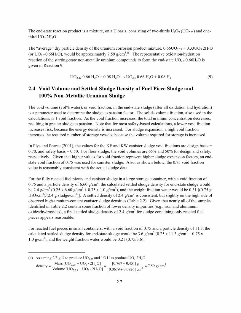
The end-state reaction product is a mixture, on a U basis, consisting of two-thirds U4O9 (UO2.25) and one-third UO3⋅2H2O. The “average” dry particle density of the uranium corrosion product mixture, 0.66UO2.25 + 0.33UO3⋅2H2O (or UO2.5⋅0.66H2O), would be approximately 7.59 g/cm3.(c) The representative oxidation/hydration reaction of the starting-state non-metallic uranium compounds to form the end-state UO2.5⋅0.66H2O is given in Reaction 9: UO2.42⋅0.66 H2O + 0.08 H2O → UO2.5⋅0.66 H2O + 0.08 H2 (9) 2.4 Void Volume and Settled Sludge Density of Fuel Piece Sludge and 100% Non-Metallic Uranium Sludge The void volume (vol% water), or void fraction, in the end-state sludge (after all oxidation and hydration) is a parameter used to determine the sludge expansion factor. The solids volume fraction, also used in the calculations, is 1 void fraction. As the void fraction increases, the total uranium concentration decreases, resulting in greater sludge expansion. Note that for most safety-based calculations, a lower void fraction increases risk, because the energy density is increased. For sludge expansion, a high void fraction increases the required number of storage vessels, because the volume required for storage is increased. In Plys and Pearce (2001), the values for the KE and KW canister sludge void fractions are design basis = 0.70, and safety basis = 0.50. For floor sludge, the void volumes are 65% and 50% for design and safety, respectively. Given that higher values for void fraction represent higher sludge expansion factors, an end-state void fraction of 0.75 was used for canister sludge. Also, as shown below, the 0.75 void fraction value is reasonably consistent with the actual sludge data. For the fully reacted fuel pieces and canister sludge in a large storage container, with a void fraction of 0.75 and a particle density of 6.60 g/cm3, the calculated settled sludge density for end-state sludge would be 2.4 g/cm3 (0.25 x 6.60 g/cm3 + 0.75 x 1.0 g/cm3), and the weight fraction water would be 0.31 [(0.75 g H2O/cm3)/(2.4 g sludge/cm3)]. A settled density of 2.4 g/cm3 is consistent, but slightly on the high side of observed high-uranium-content canister sludge densities (Table 2.2). Given that nearly all of the samples identified in Table 2.2 contain some fraction of lower density impurities (e.g., iron and aluminum oxides/hydroxides), a final settled sludge density of 2.4 g/cm3 for sludge containing only reacted fuel pieces appears reasonable. For reacted fuel pieces in small containers, with a void fraction of 0.75 and a particle density of 11.3, the calculated settled sludge density for end-state sludge would be 3.6 g/cm3 (0.25 x 11.3 g/cm3 + 0.75 x 1.0 g/cm3), and the weight fraction water would be 0.21 (0.75/3.6).
(c) Assuming 2/3 g U to produce UO2.25 and 1/3 U to produce UO3⋅2H2O.
33
2325.2
2325.2 cm/g59.7cm]0926.00679.0[g]451.0767.0[
]OH2UOUO[Volume]OH2UOUO[Massdensity =
++
=⋅+
⋅+=
2.7

For comparison, the results from the Gas Generation Series III tests were examined in which fuel fragments were reacted anoxically until no further hydrogen gas generation occurred. For Test Mid 80, the final settled sludge density was 2.7 to 2.8 g/cm3; the weight fraction water was 0.24; and the particle density of the reacted fuel fragments was measured to be 9.4 g/cm3. In the M500 test, which also was reacted anoxically to completion, the resulting settled sludge density was 2.4 g/cm3; the mass fraction water was 0.28; and the particle density was 8.9 g/cm3. These experimental density and mass fraction water values correspond reasonably well with the calculated values. 2.5 Summary of Assumed Chemistry and Parameters Used in Sludge
Expansion Factor Calculation Based on the data and assumptions presented above, Tables 2.3 and 2.4 were developed to summarize the key input parameters to calculate the sludge expansion factors, total volume expansion, and water consumption expected during storage. Table 2.3 presents the key parameters for metallic uranium fragments in large and small containers. Table 2.4 presents the same parameters for the non-metallic uranium in large and small containers.
Table 2.3. Summary of Assumed Chemistry and Physical Properties for Metallic Uranium Fuel Pieces in Large (Oxic) and Small (Anoxic) Storage Containers
Starting-State Condition/Composition Composition U(metal) Particle Density, g/cm3 19(a) Void Fraction 0.4(a) Mass Fraction Water 0.057 Settled Density, g/cm3 10.5 (accounting for zirconium)(a) U Concentration, g/cm3 9.4(a) Controlling Oxic Chemistry U(metal) + 0.188 O2 + 3.25 H2O → UO2.63⋅H2O + 2.25 H2 Controlling Anoxic Chemistry U(metal) + 2.25 H2O → UO2.25 + 2.25 H2
End-State Condition/Composition
Storage Environment Fuel Pieces in Large Containers (oxic conditions)
Fuel Pieces in Small Containers (anoxic conditions)
Composition UO2.63⋅H2O (MW(b) = 298) UO2.25 (MW = 274) Particle Density, g/cm3 6.6 11.3 Void Fraction 0.75 0.75 Solids Volume Fraction 0.25 0.25 Mass Fraction Water 0.31 0.21 Settled Density, g/cm3 2.4 3.6 Water Consumption (mol water/mol uranium converted)
3.25 2.25
(a) Values from Plys and Pearce (2001). (b) Molecular weight.
2.8

Table 2.4. Summary of Assumed Chemistry and Physical Properties of Non-Metallic Uranium in Large (Oxic) and Small (Anoxic) Storage Containers
Starting-State Condition/Composition Composition UO2.42⋅0.66 H2O (MW= 288.4) Particle Density, g/cm3 7.53 Void Fraction Depends on sludge type Settled Density, g/cm3 2.7 U Concentration, g/cm3 Depends on sludge type Controlling Oxic Chemistry UO2.42⋅0.66 H2O + 0.105 O2 + 0.34 H2O → UO2.63⋅H2O
Controlling Anoxic Chemistry UO2.42⋅0.66 H2O + 0.08 H2O → UO2.5⋅0.66 H2O + 0.08 H2
End-State Condition/Composition
Storage Environment Non-Metallic Uranium in Large Containers (Oxic Conditions)
Non-Metallic Uranium in Small Storage (Anoxic Conditions)
Composition UO2.63⋅H2O (MW = 298) UO2.5⋅0.66 H2O (MW = 290) Particle Density, g/cm3 6.6 7.59 Void Fraction 0.75 0.75 Solids Volume Fraction 0.25 0.25 Mass Fraction Water 0.31 0.28 Settled Density, g/cm3 2.4 2.65 Water Consumption (mol water/mol uranium converted)
0.34 0.08
2.9

3.0 Sludge Expansion Determinations The impacts of sludge reactions and expansions on container filling can be illustrated by three questions: 1. Sludge Level Expansion – to what extent will the settled sludge expand, assuming an excess of free
water? 2. Total Volume Expansion – to what extent will the container contents (sludge + water) expand or
contract? 3. Water Requirements – how much water is required to keep the expanded sludge wet, and how much
water is consumed as uranium compounds oxidize and convert to hydrates? These questions are addressed here. 3.1 Metallic Fuel Pieces This section addresses the sludge expansion of metallic fuel pieces (fuel piece sludge) under oxic and anoxic storage conditions. The calculated expansion values are compared to the observed sludge expansion when SNF fuel pieces were reacted with water in Gas Generation Series III testing. 3.1.1 Large Container Storage – Oxic Conditions 3.1.1.1 Sludge Expansion Factor for Fuel Pieces The sludge expansion factor is the ratio of the end-state settled sludge volume to the starting-state settled sludge volume. Therefore, the expansion factor can be determined by calculating the volume of end-state sludge that will be generated from a unit volume of starting-state sludge. In this study, it has been assumed that when starting-state sludge is placed into storage containers, sufficient free water will be added to allow the sludge to expand to its end-state condition and to account for the water consumed in chemical reactions. Starting-state basis: 1 L (1000 cm3) of fuel piece sludge + initial free water. From Plys and Pearce (2001) and Table 2.3, the starting U(metal) concentration for fuel piece sludge is
9.4 g/cm3 (settled sludge basis). Total uranium = 1000 cm3 x 9.4 g U/cm3 = 9400 g (39.5 mole) U in 1 L of fuel piece sludge. From Plys and Pearce (2001), 93.1 wt% of the fuel pieces are uranium, and 6.9 wt% are zirconium. Total zirconium = (9400/0.931) x 0.069 = 697 g zirconium in 1 L of fuel piece sludge.
3.1

After completion of the oxidation/hydration reactions (Reaction 6), the resulting sludge will consist of the uranium oxidation product (UO2.63⋅H2O), zirconium, and water. To calculate the total volume of the expanded sludge, the total particle volume of the end-state sludge can be determined and then divided by the solids volume fraction. From Table 2.3, the end-state sludge solids volume fraction is 0.25. End-state sludge generated from 1 L of fuel piece sludge Particle volume of UO2.63⋅H2O (MW = 298) = [9400 g x (298/238)]/(6.6 g/cm3) = 1780 cm3. Particle volume of zirconium = 697 g/(6.5 g/cm3) = 107 cm3. Volume of end-state sludge = (1780 cm3 UO2.63⋅H2O solids + 107 cm3 zirconium solids)/(0.25 cm3 solids/cm3 sludge) = 7548 cm3 ≈ 7500 cm3 end-state sludge. Therefore, under oxic conditions, the sludge expansion factor for the fuel piece sludge is 7.5 (7500 cm3/1000 cm3) (ratio of the end-state settled sludge volume to the starting-state settled sludge volume). 3.1.1.2 Total Volume Expansion for Fuel Pieces The difference between the volume of starting-state sludge plus initial free water and the volume of expanded end-state sludge is the total volume expansion (or contraction). For calculating the total volume expansion, it is assumed that enough water will be added to the initial fuel piece sludge (starting state) to account for water consumed in chemical reactions and result in a final expanded settled sludge that stays just wetted (i.e., no free supernatant and no un-immersed solids at completion of oxidation/hydration). The total volume expansion can be determined from a material balance around water. Starting-state basis: 1 L (1000 cm3) of fuel piece sludge + initial free water. From Plys and Pearce (2001) and Table 2.3, the void fraction of the starting-state fuel piece sludge is
0.4. Starting-state interstitial water = 1000 cm3 x 0.4 (cm3 water/cm3 sludge) = 400 cm3, or ≈ 400 g H2O. After oxidation/hydration of 1 L of starting-state fuel pieces, the expanded end-state volume = 7.5 L = particle volume of uranium oxide hydrate + particle volume of zirconium + end-state volume of water. From 3.1.1.1, particle volume of UO2.63⋅H2O = 1780 cm3. From 3.1.1.1, particle volume of zirconium = 107 cm3. End-state water = 7500 cm3 − 1780 cm3 − 107 cm3 = 5613 cm3, or ≈ 5610 g H2O.
3.2

A water balance around sludge storage can be performed to calculate the initial (starting state) free water: Initial free water + interstitial water = end-state water + water consumed. Water consumed = 3.25 mole H2O/mole U x 39.5 mole U x 18 g H2O/mole = 2310 g H2O. Initial free water = 5610 g (end-state water) + 2310 g (consumed water) − 400 g (interstitial water) = 7520 g. The initial starting-state volume of sludge plus water = 1000 cm3 (fuel piece sludge) + 7520 cm3 (initial free water) = 8520 cm3. Therefore, during storage, the total volume is expected to contract by 1020 cm3 (8520 cm3 − 7500 cm3). These calculations do not consider water losses from the container by evaporation. 3.1.2 Small Container Storage – Anoxic Conditions 3.1.2.1 Sludge Volume Expansion Factor for Fuel Pieces The starting-state basis for fuel piece sludge given in Section 3.1.1.1 is applicable to the starting-state basis for fuel piece sludge in anoxic storage: Starting-state basis: 1 L (1000 cm3) fuel piece sludge + initial free water. Total uranium = 1000 cm3 x 9.4 g U/cm3 = 9400 g (39.5 mole) U in 1 L of fuel piece sludge. Total zirconium = (9400/0.931) x 0.069 = 697 g zirconium in 1 L of fuel piece sludge. After completion of the oxidation reactions (Reaction 2), the resulting sludge will consist of UO2.25, zirconium, and water. To calculate the total volume of the expanded sludge, the total particle volume of the end-state sludge can be determined and then divided by the solids volume fraction. From Table 2.3, the end-state sludge solids volume fraction is 0.25. End-state sludge generated from 1 L of fuel piece sludge: Particle volume of UO2.25 (MW = 274) = [9400 g x (274/238)]/(11.3 g/cm3) = 958 cm3. Particle volume of zirconium = 697 g/(6.5 g/cm3) = 107 cm3.
3.3

Volume of end-state sludge = (958 cm3 UO2.25 solids + 107 cm3 zirconium solids)/(0.25 cm3 solids/cm3 sludge) = 4260 cm3 end-state sludge. Therefore, under oxic conditions, the sludge expansion factor for the fuel piece sludge is ~4.3 (4260 cm3/1000 cm3) (ratio of the end-state settled sludge volume to the starting-state settled sludge volume). If a lower particle density for anoxic uranium corrosion product was assumed (e.g., 9.0 g/cm3), then the sludge expansion factor for the fuel piece sludge would be 5.2. This example illustrates the sensitivity of the expansion factor to the particle density of the end product(s). 3.1.2.2 Crosscheck of Expansion Factor with Gas Generation Series III Data As noted in Section 2.0, the observed expansion factors from the Gas Generation Series III Tests were examined to crosscheck the calculated factor for fuel piece sludge. The Series III tests were performed for the SNF Project by PNNL to examine the chemical reaction and gas generation behavior of irradiated SNF fragments typical of those expected from elements stored at the K Basins. Portions of the fuel pieces were crushed and fractionated by particle size using wire mesh sieves. The fractionated and unfractionated fuel fragments were tested with and without KE Basin sludge addition. The sludge expansion from two tests from Series III, Mid 80 and M500, are examined in detail here. Mid 80 was conducted with fuel fragments initially between 500 and 2000 µm, and M500 was conducted with fuel fragments between 0 and 500 µm. KE Basin sludge was not added in either of these tests. Both of these tests were conducted under anoxic conditions and continued until the metallic fragments were completely reacted. From the measurement of the total gas generated, the initial quantity of uranium metal was determined. After the testing, the reaction vessels were disassembled, and measurements were made on the recovered material (settled density, mass fraction solids, and dry particle density). 3.1.2.2.1 Initial Settled Densities of Fuel Fragments. From Gas Generation III measurements, Mid 80 was determined to be 90% U metal. Post-test examinations showed that this material contained essentially no zirconium. Assuming a 90:10 by U weight mix of U(metal) and UO2 (ratio based on gas generation reactions; mixture particle density of 17.7 g/cm3 calculated as shown in footnotes a and b, pp. 2.4 and 2.6, respectively) and a 40% void volume, the settled density at the start of the test was: = 0.6 (cm3 solids/cm3 sludge) x 17.7 (g solids/cm3 solids) + 0.4 (cm3 water/cm3 sludge) x 1 (g water/cm3 water) = 11.0 g/cm3 sludge for Mid 80.
3.4
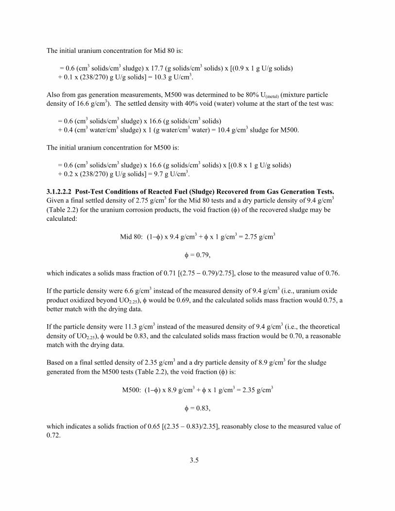
The initial uranium concentration for Mid 80 is: = 0.6 (cm3 solids/cm3 sludge) x 17.7 (g solids/cm3 solids) x [(0.9 x 1 g U/g solids) + 0.1 x (238/270) g U/g solids] = 10.3 g U/cm3. Also from gas generation measurements, M500 was determined to be 80% U(metal) (mixture particle density of 16.6 g/cm3). The settled density with 40% void (water) volume at the start of the test was: = 0.6 (cm3 solids/cm3 sludge) x 16.6 (g solids/cm3 solids) + 0.4 (cm3 water/cm3 sludge) x 1 (g water/cm3 water) = 10.4 g/cm3 sludge for M500. The initial uranium concentration for M500 is: = 0.6 (cm3 solids/cm3 sludge) x 16.6 (g solids/cm3 solids) x [(0.8 x 1 g U/g solids) + 0.2 x (238/270) g U/g solids] = 9.7 g U/cm3. 3.1.2.2.2 Post-Test Conditions of Reacted Fuel (Sludge) Recovered from Gas Generation Tests. Given a final settled density of 2.75 g/cm3 for the Mid 80 tests and a dry particle density of 9.4 g/cm3 (Table 2.2) for the uranium corrosion products, the void fraction (φ) of the recovered sludge may be calculated:
Mid 80: (1−φ) x 9.4 g/cm3 + φ x 1 g/cm3 = 2.75 g/cm3
φ = 0.79, which indicates a solids mass fraction of 0.71 [(2.75 − 0.79)/2.75], close to the measured value of 0.76. If the particle density were 6.6 g/cm3 instead of the measured density of 9.4 g/cm3 (i.e., uranium oxide product oxidized beyond UO2.25), φ would be 0.69, and the calculated solids mass fraction would 0.75, a better match with the drying data. If the particle density were 11.3 g/cm3 instead of the measured density of 9.4 g/cm3 (i.e., the theoretical density of UO2.25), φ would be 0.83, and the calculated solids mass fraction would be 0.70, a reasonable match with the drying data. Based on a final settled density of 2.35 g/cm3 and a dry particle density of 8.9 g/cm3 for the sludge generated from the M500 tests (Table 2.2), the void fraction (φ) is:
M500: (1−φ) x 8.9 g/cm3 + φ x 1 g/cm3 = 2.35 g/cm3 φ = 0.83, which indicates a solids fraction of 0.65 [(2.35 − 0.83)/2.35], reasonably close to the measured value of 0.72.
3.5
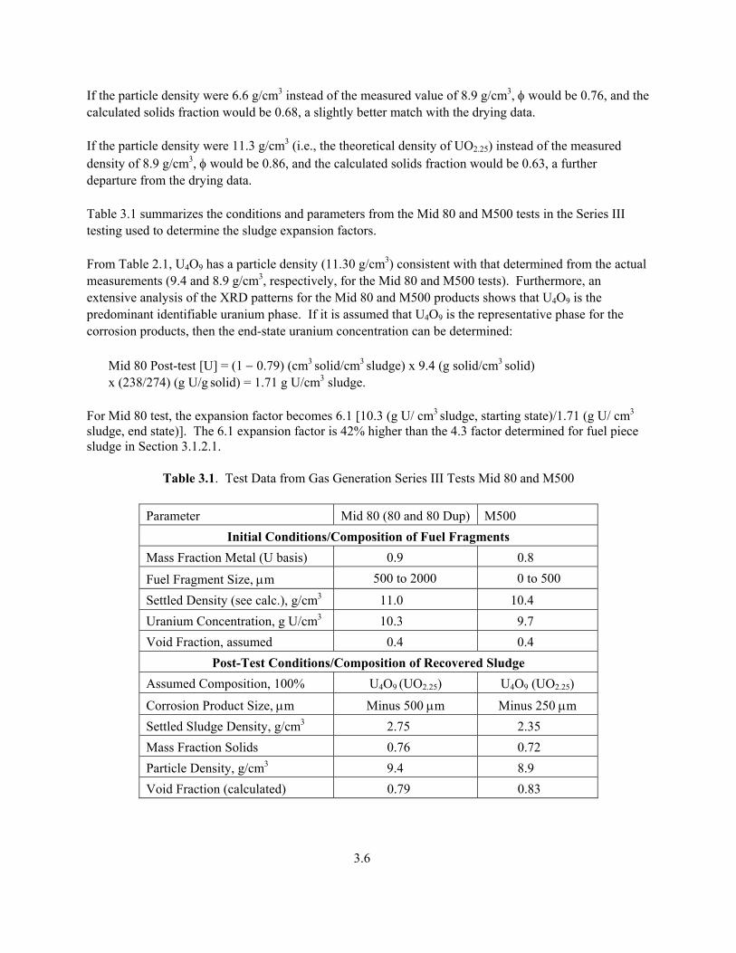
If the particle density were 6.6 g/cm3 instead of the measured value of 8.9 g/cm3, φ would be 0.76, and the calculated solids fraction would be 0.68, a slightly better match with the drying data. If the particle density were 11.3 g/cm3 (i.e., the theoretical density of UO2.25) instead of the measured density of 8.9 g/cm3, φ would be 0.86, and the calculated solids fraction would be 0.63, a further departure from the drying data. Table 3.1 summarizes the conditions and parameters from the Mid 80 and M500 tests in the Series III testing used to determine the sludge expansion factors. From Table 2.1, U4O9 has a particle density (11.30 g/cm3) consistent with that determined from the actual measurements (9.4 and 8.9 g/cm3, respectively, for the Mid 80 and M500 tests). Furthermore, an extensive analysis of the XRD patterns for the Mid 80 and M500 products shows that U4O9 is the predominant identifiable uranium phase. If it is assumed that U4O9 is the representative phase for the corrosion products, then the end-state uranium concentration can be determined: Mid 80 Post-test [U] = (1 − 0.79) (cm3 solid/cm3 sludge) x 9.4 (g solid/cm3 solid) x (238/274) (g U/g solid) = 1.71 g U/cm3 sludge. For Mid 80 test, the expansion factor becomes 6.1 [10.3 (g U/ cm3 sludge, starting state)/1.71 (g U/ cm3
sludge, end state)]. The 6.1 expansion factor is 42% higher than the 4.3 factor determined for fuel piece sludge in Section 3.1.2.1.
Table 3.1. Test Data from Gas Generation Series III Tests Mid 80 and M500
Parameter Mid 80 (80 and 80 Dup) M500 Initial Conditions/Composition of Fuel Fragments
Mass Fraction Metal (U basis) 0.9 0.8
Fuel Fragment Size, µm 500 to 2000 0 to 500
Settled Density (see calc.), g/cm3 11.0 10.4 Uranium Concentration, g U/cm3 10.3 9.7 Void Fraction, assumed 0.4 0.4
Post-Test Conditions/Composition of Recovered Sludge Assumed Composition, 100% U4O9 (UO2.25) U4O9 (UO2.25)
Corrosion Product Size, µm Minus 500 µm Minus 250 µm Settled Sludge Density, g/cm3 2.75 2.35 Mass Fraction Solids 0.76 0.72 Particle Density, g/cm3 9.4 8.9 Void Fraction (calculated) 0.79 0.83
3.6

Similarly, the end-state uranium concentration for M500 is: M500 Post-test [U] = (1 − 0.83) (cm3 solid/cm3 sludge) x 8.9 (g solid/cm3 solid) x (238/274) (g U/g solid) = 1.31 g U/cm3 sludge. For the M500 test, the expansion factor becomes 7.4 [9.7 (g U/cm3 sludge, starting state)/1.31 (g U/cm3
sludge, end state)]. The 7.4 expansion factor is 72% higher than the 4.3 factor determined for fuel piece sludge in Section 3.1.2.1. The fact that the sludge expansion factors determined for the fuel fragments (U(metal)) reacting to sludge (U4O9) in the gas generation tests are significantly greater than the calculated 4.3 factor may partially be attributed to the settled sludge measurements. For the Mid 80 and M500 post-test residual sludge, the measurements of the settled sludge density were made with ~7 cm3 and ~3 cm3 of sludge, respectively. With a larger quantity and depth of material, the sludge would be expected to undergo further consolida-tion, resulting in a higher settled density and lower water content. While XRD analysis supports that UO2.25 was the predominant uranium phase in this material, it is possible slight water adsorption or further oxidation occurred between the time the residual corrosion products were recovered from the gas generation test containers and the dry particle density measurements were made. Given the relatively large difference between the calculated and “measured” sludge expansion factors, it may be prudent to use a value of ~5 as the expansion factor for calculating sludge fill levels. 3.1.2.3 Total Volume Expansion for Fuel Pieces The difference between the volume of starting-state sludge plus initial free water and the volume of expanded end-state sludge is the total volume expansion (or contraction). To calculate the total volume expansion, it is assumed that enough water will be added to the initial fuel piece sludge (starting state) to account for water consumed in chemical reactions and result in a final expanded settled sludge that stays just wetted (i.e., no free supernatant and no un-immersed solids at completion of oxidation/hydration). The total volume expansion can be determined from a material balance around water. Starting-state basis: 1 L (1000 cm3) of fuel piece sludge + initial free water. From Plys and Pearce (2001) and Table 2.3, the void fraction of the starting-state fuel piece sludge is
0.4. Starting-state interstitial water = 1000 cm3 x 0.4 (cm3 water/cm3 sludge) = 400 cm3, or ≈ 400 g H2O. After oxidation/hydration of 1 L of starting-state fuel pieces, the expanded end-state volume = 4.3 L = particle volume of UO2.25 + particle volume of zirconium + end-state volume of water. From 3.1.2.1, particle volume of UO2.25 = 958 cm3. From 3.1.2.1, particle volume of zirconium = 107 cm3.
3.7

End-state water = 4300 cm3 − 958 cm3 − 107 cm3 = 3235 cm3 ≈ 3240 cm3, or 3240 g H2O. A water balance around sludge storage can be performed to calculate the initial (starting state) free water: Initial free water + interstitial water = end-state water + water consumed. Water consumed = 2.25 mole H2O/mole U x 39.5 mole U x 18 g H2O/mole = 1600 g H2O. Initial free water = 3240 g (end-state water) + 1600 g (consumed water) − 400 g (interstitial water) = 4440 g. The initial starting-state volume of sludge plus water is: = 1000 cm3 (fuel piece sludge) + 4440 cm3 (initial free water) = 5440 cm3. Therefore, during storage, the total volume is expected to contract by 1140 cm3 (5440 cm3 − 4300 cm3). These calculations do not consider water losses from the container by evaporation. 3.2 KE Canister Sludge The volume of KE canister sludge is expected to be significantly greater than that of KW canister sludge. During fuel transfer from KE to KW, a significant portion of the KE canister sludge is expected to fall out of the canisters onto the KE Basin floor and ultimately be loaded into large containers. The remaining KE canister sludge will be transferred to the KW Basin during fuel movement. In the KW Basin, this sludge will become mixed with the knockout pot and settler tube sludge during fuel washing and ultimately loaded into small storage containers. The KE canister sludge (as reported in Plys and Pearce 2001) nominally contains 0.77 g U/cm3, has a total dry solids concentration of 1.18 g/cm3 (i.e., the canister sludge is 65 wt% U, dry basis), and has a settled sludge density of 1.87 g/cm3. The key safety basis values for KE canister sludge are:
• void fraction = 0.5 • settled sludge density = 2.5 g/cm3 • total uranium concentration = 1.5 g U/cm3 • U(metal) concentration = 5 wt% (settled sludge) = 0.05 x 2.5 g/cm3 = 0.125 g U/cm3.
For the canister sludge expansion factor calculations, a slightly higher settled sludge density (2.7 g/cm3) has been assumed. However, the safety basis values for the total uranium and the U(metal) concentrations are used. A void fraction of 0.70, which is slightly lower than the end-state value of 0.75, is used for the calculations.
3.8
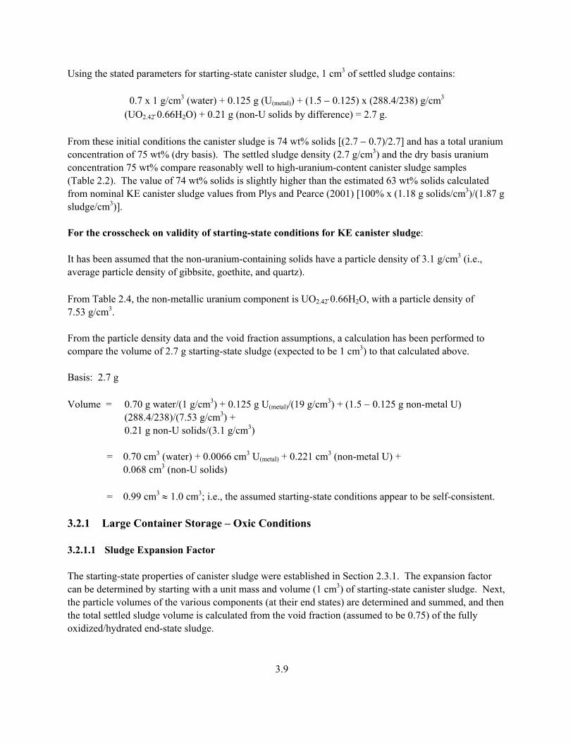
Using the stated parameters for starting-state canister sludge, 1 cm3 of settled sludge contains:
0.7 x 1 g/cm3 (water) + 0.125 g (U(metal)) + (1.5 − 0.125) x (288.4/238) g/cm3
(UO2.42⋅0.66H2O) + 0.21 g (non-U solids by difference) = 2.7 g. From these initial conditions the canister sludge is 74 wt% solids [(2.7 − 0.7)/2.7] and has a total uranium concentration of 75 wt% (dry basis). The settled sludge density (2.7 g/cm3) and the dry basis uranium concentration 75 wt% compare reasonably well to high-uranium-content canister sludge samples (Table 2.2). The value of 74 wt% solids is slightly higher than the estimated 63 wt% solids calculated from nominal KE canister sludge values from Plys and Pearce (2001) [100% x (1.18 g solids/cm3)/(1.87 g sludge/cm3)]. For the crosscheck on validity of starting-state conditions for KE canister sludge: It has been assumed that the non-uranium-containing solids have a particle density of 3.1 g/cm3 (i.e., average particle density of gibbsite, goethite, and quartz). From Table 2.4, the non-metallic uranium component is UO2.42⋅0.66H2O, with a particle density of 7.53 g/cm3. From the particle density data and the void fraction assumptions, a calculation has been performed to compare the volume of 2.7 g starting-state sludge (expected to be 1 cm3) to that calculated above. Basis: 2.7 g Volume = 0.70 g water/(1 g/cm3) + 0.125 g U(metal)/(19 g/cm3) + (1.5 − 0.125 g non-metal U) (288.4/238)/(7.53 g/cm3) + 0.21 g non-U solids/(3.1 g/cm3) = 0.70 cm3 (water) + 0.0066 cm3 U(metal) + 0.221 cm3 (non-metal U) + 0.068 cm3 (non-U solids) = 0.99 cm3 ≈ 1.0 cm3; i.e., the assumed starting-state conditions appear to be self-consistent. 3.2.1 Large Container Storage – Oxic Conditions 3.2.1.1 Sludge Expansion Factor The starting-state properties of canister sludge were established in Section 2.3.1. The expansion factor can be determined by starting with a unit mass and volume (1 cm3) of starting-state canister sludge. Next, the particle volumes of the various components (at their end states) are determined and summed, and then the total settled sludge volume is calculated from the void fraction (assumed to be 0.75) of the fully oxidized/hydrated end-state sludge.
3.9

The end-state particle volume of UO2.63⋅H2O, formula weight 298 g, plus non-uranium sludge (starting with 1 cm3 of starting-state canister sludge) is: End-state volume of expanded particles = 1.5 g U/cm3 x (298/238)/(6.6 g/cm3) + 0.21 g/(3.1 g non-U solids/cm3) = 0.35 cm3 solids. End-state settled solids volume = 0.35 cm3 solids x (1 cm3 sludge/0.25 cm3 solids) = 1.40 cm3. Expansion factor = (end-state volume)/(starting-state volume) = 1.4 cm3/1 cm3 = 1.4. Therefore, during storage, the canister settled sludge volume is expected to increase by about 40%. 3.2.1.2 Total Volume Expansion for KE Canister Sludge For calculating the total volume expansion, it has been assumed that enough water will be added to the initial canister sludge (starting state) to result in a final expanded settled sludge that stays just wetted (i.e., no free supernatant and no un-wetted solids at completion of oxidation and hydration). Starting basis: 1 L (1000 cm3) of canister sludge + initial free water. U(metal) = 1000 cm3 x 0.125 g U/cm3 = 125 g U (0.53 mole U(metal))/L canister sludge. Water consumed in reactions with U(metal) (Reaction 6) = 3.25 moles H2O/mole U x 0.53 moles U x 18 g H2O/mole H2O = 31.0 g H2O. Non-metallic uranium = 1000 cm3 x (1.5 − 0.125) g U/cm3 = 1375 g (5.78 mole) U/L canister sludge. Water consumed in conversion of non-metallic U (Reaction 7) = 0.34 mole H2O/mole U x 5.8 mole U x 18 g H2O/mole H2O = 35.5 g H2O. Non-uranium solids = 0.21 g/cm3 x 1000 cm3 = 210 g. Starting-state interstitial water = 0.7 x 1000 cm3 = 700 cm3 ≈ 700 g. After oxidation/hydration of 1 L of starting-state canister sludge, the expanded end-state volume, 1.4 L = particle volume of uranium oxide hydrate + particle volume of non-uranium solids + end-state volume of water. Volume of UO2.63⋅H2O = [1.5 g U/cm3 x 1000 cm3 x (298/238)]/(6.60 g/cm3) = 285 cm3. Volume of non-uranium solids = 0.21 g/cm3 x 1000 cm3/(3.1 g/cm3) = 68 cm3.
3.10

End-state water = 1400 cm3 – 285 cm3 – 68 cm3 = 1047 cm3 = 1050 g. A water balance around sludge storage can be performed to calculate the initial (starting state) free water: Initial free water + interstitial water = end-state water + water consumed. Water consumed = 31.0 g H2O + 35.5 g H2O = 66.5 g H2O. Initial free water = 1050 g + 66.5 g – 700 g = 417 g, or ≈ 420 cm3. The initial starting-state volume of sludge plus water = 1000 cm3 (fuel piece sludge) + 420 cm3 (initial free water) = 1420 cm3. Therefore, during storage, the total volume is expected to contract by 20 cm3 (1420 cm3 − 1400 cm3). These calculations do not consider water losses from the container by evaporation. 3.2.2 Small Container Storage – Anoxic Conditions 3.2.2.1 Sludge Volume Expansion Factor The starting-state properties of canister sludge were established in Section 2.3.1. The expansion factor can be determined by starting with a unit mass and volume (1 cm3) of starting-state canister sludge. Next, the particle volumes of the various components (at their end states) are determined and summed, and the total settled sludge volume is calculated from the void fraction (assumed to be 0.75) of the fully oxidized/hydrated sludge. The end-state particle volume of UO2.25 [from the U(metal)], UO2.5⋅0.66H2O (formula weight 290 g from non-metallic uranium), plus non-uranium sludge, starting with 1 cm3 of starting-state canister sludge is: End-state volume of expanded particles = 0.125 g U(metal) x (274/238)/(11.3 g/cm3) + (1.5 − 0.125) g U/cm3 x (290/238)/(7.6 g/cm3) + 0.21 g/(3.1 g/cm3) = 0.30 cm3 solids. End-state settled solids volume = 0.30 cm3 solids x (1 cm3 sludge/0.25 cm3 solids) = 1.2 cm3. Expansion factor = (end-state volume)/(starting-state volume) = 1.2 cm3/1 cm3 = 1.2. Therefore, the canister settled sludge volume is expected to increase by about 20% under anoxic conditions in the small storage containers.
3.11

3.2.2.2 Total Volume Expansion for KE Canister Sludge For calculating the total volume expansion, it has been assumed that enough water will be added to the initial canister sludge (starting state) to result in a final expanded settled sludge that stays just wetted (i.e., no free supernatant at completion of oxidation and hydration). Starting basis: 1 L (1000 cm3) of canister sludge + initial free water. U(metal) = 1000 cm3 x 0.125 g U/cm3 = 125 g U (0.53 mole U(metal))/L canister sludge. Water consumed in reactions with U(metal) (Reaction 6) = 2.25 moles H2O/mole U x 0.53 moles U x 18 g H2O/mole H2O = 21.5 g H2O. Non-metallic uranium = 1000 cm3 x (1.5 − 0.125) g U/cm3 = 1375 g (5.78 mole) U/L canister sludge. Water consumed in conversion of non-metallic U (Reaction 7) = 0.08 mole H2O/mole U x 5.8 mole U x 18 g H2O/mole H2O = 8.4 g H2O. Non-uranium solids = 0.21 g/cm3 x 1000 cm3 = 210 g. Starting-state interstitial water = 0.7 x 1000 cm3 = 700 cm3 ≈ 700 g. After oxidation/hydration of 1 L of starting-state canister sludge, the expanded end-state volume, 1.2 L = particle volume of uranium oxide + particle volume of uranium oxide hydrate + particle volume of non-uranium solids + end-state volume of water. Volume of UO2.25 = [0.125 gU/cm3 x 1000 x 274/238)]/11.3 g/cm3 = 12.7 cm3. Volume of UO2.5⋅0.66H2O = [(1.5 − 0.125) g U/cm3 x 1000 cm3 x (290/238)]/(7.6 g/cm3) = 220 cm3.
Volume of non-uranium solids = 0.21 g/cm3 x 1000 cm3/(3.1 g/cm3) = 68 cm3.
End-state water = 1200 cm3 − 12.7 cm3 − 220 cm3 − 68 cm3 = 899.3 cm3 ≈ 900 g. A water balance around sludge storage can be performed to calculate the initial (starting state) free water: Initial free water + interstitial water = end-state water + water consumed. Water consumed = 21.5 g H2O + 8.4 g H2O = 29.9 g H2O. Initial free water = 900 g + 30 g – 700 g = 230 cm3.
3.12
The initial starting-state volume of sludge plus water = 1000 cm3 (fuel piece sludge) + 230 cm3 (initial free water) = 1230 cm3. Therefore, during storage, the total volume would be expected to contract by 30 cm3 (1230 cm3 − 1200 cm3). These calculations do not consider water losses from the container by evaporation. 3.3 KW Canister Sludge The KW canister sludge is expected to become mixed with the knockout pot and settler tube sludge during fuel washing and ultimately loaded into small storage containers. Therefore, for KW canister sludge, expansion is evaluated under anoxic storage only. The KW canister sludge (as reported in Plys and Pearce 2001) nominally contains 1.5 g U/cm3, has a settled sludge density of 2.7 g /cm3, and a void fraction of 0.70. The key safety basis values for KW canister sludge are:
• void fraction = 0.5 • settled sludge density = 4.0 g/cm3 • total uranium concentration = 2.75 g U/cm3 • U(metal) concentration = 5 wt% (settled sludge) = 0.05 x 4.0 g/cm3 = 0.200 g U/cm3.
As with the KE canister sludge, for the expansion factor calculations, the safety basis values for the total uranium and the U(metal) concentrations are used. A starting-state void fraction of 0.70, which is slightly lower than the end-state value of 0.75, is used for the calculations. For the KW canister sludge, it has been assumed for these calculations that the non-metallic uranium is in the same form (i.e., UO2.42⋅0.66H2O) as the starting-state non-metallic uranium in the KE canister sludge. Given the anoxic storage conditions of the KW fuel, and the presence of corrosion inhibitors in the sealed canisters, it is likely the uranium species in the KW canister sludge are less oxidized than those in the KE canister sludge. Using the parameters for starting-state KW canister sludge, 1 cm3 of settled sludge contains:
0.7 x 1 g/cm3 (water) + 0.2 g (U(metal)) + (2.75 − 0.200) x (288.4/238) g/cm3
(UO2.42⋅0.66H2O) + 0.0 g (non-U solids by difference) = 4.0 g. Solving the above equation results in a prediction that KW canister sludge contains no non-uranium solids. Actual laboratory results show that the KW canister sludge contains low concentrations of impurities, including grafoil, iron, and aluminum.
3.13

From these initial conditions the KW canister sludge is 83 wt% solids [(4.0 − 0.7)/4.0] and has a total uranium concentration of 83 wt% (dry basis). The settled sludge density (4.0 g/cm3) and the dry basis uranium concentration 83 wt% compare reasonably well to KW canister sludge samples 96-16 and 96-17 in Table 2.2. 3.3.1 Sludge Volume Expansion Factor (Small Container Storage - Anoxic Conditions) The starting-state composition of non-metal uranium compounds in the KW canister sludge is assumed to be the same as that established for the KE canister sludge. The expansion factor can be determined by starting with a unit mass and volume (1 cm3) of starting-state canister sludge. Next, the particle volumes of the various components (at their end states) are determined and summed, and the total settled sludge volume is calculated from the void fraction (assumed to be 0.75) of the fully oxidized/hydrated sludge. The end-state particle volume of UO2.25 [from the U(metal)], UO2.5⋅0.66H2O (formula weight 290 g from non-metallic uranium), plus non-uranium sludge, starting with 1 cm3 of starting-state canister sludge is: End-state volume of expanded particles = 0.200 g U x (274/238)/(11.3 g/cm3) + (2.75 − 0.200) g U/cm3 x (290/238)/(7.6 g/cm3) = 0.43 cm3 solids. End-state settled solids volume = 0.43 cm3 solids x (1 cm3 sludge/0.25 cm3 solids) = 1.72 cm3. Expansion factor = (end-state volume)/(starting-state volume) = 1.72 cm3/1 cm3 = 1.72 ≈ 1.7. Therefore, the canister settled sludge volume is expected to increase by about 70% under anoxic conditions in the small storage containers. 3.3.2 Total Volume Expansion for KW Canister Sludge For calculating the total volume expansion, it has been assumed that enough water will be added to the initial canister sludge (starting state) to result in a final expanded settled sludge that stays just wetted (i.e., no free supernatant at completion of oxidation and hydration). Starting basis: 1 L (1000 cm3) of canister sludge + initial free water. U(metal) = 1000 cm3 x 0.200 g U/cm3 = 200 g U (0.84 mole U(metal))/L canister sludge. Water consumed in reactions with U(metal) (Reaction 6) = 2.25 moles H2O/mole U x 0.84 moles U x 18 g H2O/mole H2O = 34.0 g H2O.
3.14
Non-metallic uranium = 1000 cm3 x (2.75 − 0.200) g U/cm3 = 2550 g (10.7 mole) U/L canister sludge. Water consumed in conversion of non-metallic U (Reaction 7) = 0.08 mole H2O/mole U x 10.7 mole U x 18 g H2O/mole H2O = 15.4 g H2O. Starting-state interstitial water = 0.7 x 1000 cm3 = 700 cm3 ≈ 700 g. After oxidation/hydration of 1 L of starting-state canister sludge, the expanded end-state volume, 1.7 L = particle volume of uranium oxide + particle volume of uranium oxide hydrate + end-state volume of water. Volume of UO2.25 = [0.200 g U/cm3 x 1000 x 274/238)]/11.3 g/cm3 = 20.4 cm3. Volume of UO2.5⋅0.66H2O = [(2.75 − 0.200) g U/cm3 x 1000 cm3 x (290/238)]/(7.6 g/cm3) = 409 cm3.
End-state water = 1700 cm3 − 20.4 cm3 – 409 cm3 = 1270.6 cm3, or ≈ 1270 g. A water balance around sludge storage can be performed to calculate the initial (starting state) free water: Initial free water + interstitial water = end-state water + water consumed. Water consumed = 34.0 g H2O + 15.4 g H2O = 49.4 g H2O. Initial free water = 1270 g + 49 g − 700 g = 619 g, or ≈ 620 cm3. The initial starting-state volume of sludge plus water = 1000 cm3 (fuel piece sludge) + 620 cm3 (initial free water) = 1620 cm3. Therefore, during storage, the total volume is expected to expand by 80 cm3 (1700 cm3 − 1620 cm3). These calculations do not consider water losses from the container by evaporation. 3.4 KE Floor Sludge All KE floor sludge will be stored in large storage containers. The assumptions established for uranium metal pieces and non-metallic uranium corrosion under oxic conditions (Section 2.0) are used to calculate the expansion of the uranium component in KE floor sludge. Furthermore, it is assumed that the non-uranium species in the floor sludge will not undergo reaction and expansion during storage.
3.15

The key safety basis values for floor sludge are (Plys and Pearce 2001):
• void fraction = 0.5 • settled sludge density = 1.5 g/cm3 • total uranium concentration = 0.15 g U/cm3 • U(metal) concentration is 1.5 wt% (settled sludge) = 0.015 x 1.5 g/cm3 = 0.023 g/cm3.
With the exception of the void fraction, the safety basis values have been used to determine the floor sludge expansion factor. To achieve reasonable and consistent values for settled sludge properties (wt% solids, non-U solids concentration), and consistency with actual data, a void fraction of 0.8 is used for floor sludge before and after final oxidation/hydration (i.e., starting state and end state). Using the stated parameters of the starting-state floor sludge, 1 cm3 (1.5 g) of sludge contains: 0.8 x 1 g (water) + 0.023 g (U(metal)) + (0.15 – 0.023) x (288.4/238) g (UO2.42⋅0.66H2O) + 0.52 g (non-U solids by difference) = 1.5 g. A void fraction of 0.8 results in a weight fraction water of 0.8/1.5 = 0.53 or 53 wt% water and 47 wt% solids. The total uranium concentration (dry solid basis) is 21 wt%. 3.4.1 Crosscheck on Validity of Floor Sludge Starting State It has been assumed that the non-uranium-containing solids have a particle density of 3.1 g/cm3 (i.e., average of gibbsite, goethite, and quartz). From Table 2.3, the non-metallic uranium component is UO2.42·0.66H2O with a particle density of 7.53 g/cm3 (footnote b, p. 2.6). To crosscheck the assumptions, the volume of 1.5 g (should equal 1 cm3) of starting-state settled sludge has been calculated from the void fraction and particle masses and densities: Basis: 1.5 g KE floor sludge Volume: = 0.80 g/(1 g/cm3) (water) + 0.023 g/(19 g/cm3) (U(metal)) + (0.15 − 0.023) g x (288.4/238)/(7.53 g/cm3) (non-metal U) + 0.52 g/(3.1 g/cm3) (non-uranium solids) = 0.80 cm3 (water) + 0.0012 cm3 (U(metal)) + 0.020 cm3 (non-metal U) + 0.17 cm3 (non-uranium) = 0.989 cm3 → starting-state floor sludge values yield self-consistent results. Solids (only) Volume = 0.989 cm3 (total volume) – 0.80 cm3 (water) = 0.189 cm3 (Note: this value is also the starting-state solids volume for KE floor sludge.)
3.16

3.4.2 Sludge Volume Expansion Factor for Floor Sludge in Large Container Storage For the floor sludge, the expansion factor can be determined by starting with a unit mass and volume (1 cm3) of starting-state sludge. Next, the particle volumes of the various components (at their end states) are determined and compared to the starting-state particle volume. Since the starting-state and end-state void fractions are the same (0.80), the expansion factor is the ratio of end-state particle volume to starting-state particle volume. The end-state volume of UO2.63⋅H2O, formula weight 298 g and density of 6.60 g/cm3 (footnote a, p. 2.4) plus non-uranium sludge, starting with 1.5 g (1 cm3) initial floor sludge: End-state particle volume = 0.15 g x (298/238)/(6.60 g/cm3) + 0.52 g/(3.1 g/cm3) = 0.196 cm3 solids. Expansion factor = (end-state particle volume)/(starting-state particle volume) = 0.196 cm3/0.189 cm3 = 1.037 ≈ 1.04. Therefore, the KE floor sludge is expected to expand about 4% during oxic storage in large containers. 3.4.3 Total Volume Expansion for KE Floor Sludge For calculating the total volume expansion, it has been assumed that enough water will be added to the initial floor sludge (starting state) to result in a final expanded settled sludge that stays just wetted (i.e., no free supernatant at completion of oxidation and hydration). Starting basis: 1 L (1000 cm3) of canister sludge + initial free water. U(metal) = 1000 cm3 x 0.023 g U/cm3 = 23 g U (0.0097 mole U(metal))/L floor sludge. Water consumption in metal conversion (Reaction 6) = 3.25 mole H2O/mole U x 0.097 mole U x 18 g H2O/mole H2O = 5.7 g H2O. Non-metallic uranium = 1000 cm3 x (0.15 − 0.023) g U/cm3 = 127 g (0.53 mole) U/L floor sludge. Water consumed in conversion of non-metallic uranium (Reaction 7) = 0.34 mole H2O/mole U x 0.53 mole U x 18 g H2O/mole H2O = 3.2 g H2O. Non-uranium solids = 0.52 g/cm3 x 1000 cm3 = 520 g. Starting-state interstitial water = 0.8 x 1000 cm3 = 800 cm3 ≈ 800 g.
3.17

After oxidation/hydration of 1 L of starting-state floor sludge, the expanded end-state volume, 1.04 L = particle volume of uranium oxide hydrate + particle volume of non-uranium solids + end-state volume of water. Volume of UO2.63⋅H2O = [0.15 g U/cm3 x 1000 cm3 x (298/238)]/(6.60 g/cm3) = 28.5 cm3. Volume of non-uranium solids = 0.52 g/cm3 x 1000 cm3/(3.1 g/cm3) = 168 cm3. End-state water = 1040 cm3 − 28.5 cm3 − 168 cm3 = 844 cm3 ≈ 844 g. A water balance around sludge storage can be performed to calculate the initial (starting state) free water: Initial free water + interstitial water = end-state water + water consumed. Total water consumed in conversion of 1 L of floor sludge = 8.9 g (5.7 + 3.2). Initial free water = 844 g + 8.9 g – 800 g = 53 g, or ≈ 53 cm3. The initial starting-state volume of sludge plus water = 1000 cm3 (fuel piece sludge) + 53 cm3 (initial free water) = 1053 cm3. Therefore, during storage, the total volume is expected to contract by 13 cm3 (1053 cm3 − 1040 cm3). These calculations do not consider water losses from the container by evaporation. 3.5 50/50 Volume Mixture of Fuel Piece Sludge and KE Canister Sludge in
Small Containers The expansion factors for fuel piece and KE canister sludge were determined on a volumetric basis. Additionally, at their end states, these two sludge types have been assumed to have the same void fraction (0.7). Therefore, the expansion factor for the sludge mixture can be determined as the linear average of the two sludge types under anoxic conditions. 3.5.1 Sludge Volume Expansion Factor for 50/50 Mix in Small Containers Under anoxic conditions, 1 L of fuel piece sludge expands to 4.3 L. Under anoxic conditions, 1 L of KE canister sludge expands to 1.2 L. The expansion factor of a 50/50 volume mixture is 0.5 x (4.3 + 1.2) = 2.75 ≈ 2.8; that is, 1 L of the mixed sludge will expand to 2.8 L.
3.18

3.5.2 Total Volume of Expanded Sludge Starting-state basis: 1 L of mixed sludge (0.5 L of fuel piece sludge + 0.5 L of KE canister sludge) + initial free water. Ending state: 2.8 L of expanded sludge, wetted, but no free water. As shown previously, under anoxic conditions, the water consumption for corrosion of 1 L of fuel piece sludge is 1600 g H2O (or 800 g for 0.5 L of fuel piece sludge). Similarly, under anoxic conditions, the water consumption for corrosion of 1 L of KE canister sludge is 30 g H2O (or 15 g for 0.5 L of KE canister sludge). Therefore, for 1 L of the 50/50 (vol) mixture of the mixed sludge, a total of 815 g H2O (800 + 15) is consumed during corrosion. The starting-state volume (sludge + initial free water) (from Sections 3.1.2.3 and 3.2.2.2) = 0.5 (5440 cm3 + 1230 cm3 ) = 3335 cm3. Total contraction = 3335 cm3 – 2750 cm3 = 585 cm3 ≈ 590 cm3. On a container-loading basis, the maximum 50/50 sludge loading will be limited to about 30% [(1000/(3335) x 100%] of the container volume (assuming no initial air freeboard and no evaporation during storage). 3.6 50/50 Volume Mixture of KE Canister and KE Floor Sludge in Large
Containers The expansion factors for KE canister sludge and KE floor sludge were determined on a volumetric basis. Additionally, at their end states, these two sludge types have been assumed to have similar void fractions (0.7 and 0.8, canister and floor, respectively). Therefore, the expansion factor for the sludge mixture can be approximated as the linear average of the two sludge types under oxic conditions. 3.6.1 Sludge Volume Expansion Factor for 50/50 Mix in Large Containers Under oxic conditions, 1 L of KE canister sludge expands to 1.4 L. Under oxic conditions, 1 L of KE floor sludge expands to 1.04 L. The expansion factor of a 50/50 volume mixture is 0.5 x (1.4 + 1.04) = 1.22; that is, 1 L of the mixed sludge will expand to 1.22 L. 3.6.2 Total Volume of Expanded Sludge Starting-State basis: 1 L of mixed sludge (0.5 L KE canister sludge + 0.5 L KE floor sludge) + initial free water.
3.19

Ending state: 1.22 L of expanded sludge, wetted, but no free water. As shown previously, under oxic conditions, the water consumption for corrosion of 1 L of KE canister sludge is 66.5 g H2O (or 33.3 g for 0.5 L of KE canister sludge). Similarly, under anoxic conditions, the water consumption for corrosion of 1 L of KE floor sludge is 8.9 g H2O (or 4.5 g for 0.5 L of KE canister sludge). Therefore, for 1 L of the 50/50 (vol) mixture of the mixed sludge, a total of 37.8 g H2O (33.5 + 4.5) is consumed during corrosion. The starting-state volume (sludge + initial free water) (from Sections 3.2.1.2 and 3.3.3) = 0.5 (1420 cm3 + 1050 cm3) = 1240 cm3. Total contraction = 1240 − 1220 = 20 cm3. On a container-loading basis, the maximum 50/50 canister/floor sludge loading will be limited to about 81% [(1000/(1240) x 100%] of the container volume (assuming no initial air freeboard and no evaporation during storage).
3.20

4.0 Worst-Case Expansion of Fuel Piece Sludge (Oxic Storage Conditions)
In this section, two cases are examined that would apply if pure fuel piece sludge was placed into a large container (with good aeration), and the maximum possible uranium oxidation and hydration occurred. The cases examine slightly different controlling chemistries with the reaction products meta schoepite and studtite (both of which have been identified in K Basin sludge). These cases are useful to establish bounding conditions for evaluating the storage of pure fuel piece sludge in large containers. 4.1 Expansion of Fuel Piece Sludge to Form Meta Schoepite (UO ·2H3 2O) Testing in the Gas Generation III series shows that, under anoxic conditions, uranium metal fuel corrodes to form the uraninite phases UO2 and UO2.25. As seen in oxygenated natural systems and in long-term tests for the Yucca Mountain repository (Wronkiewicz et al. 1996), uraninite (UO2.0-2.33) readily oxidizes to form meta schoepite (UO3·2H2O). Schoepite, given access to dissolved sodium, potassium, magnesium, calcium, and silica, then can undergo stepwise paragenetic transformation to form alkali and alkaline earth uranates (e.g., becquerelite), uranyl silicates (e.g., soddyite), and finally alkali or alkaline earth uranyl silicates (e.g., uranophane). The K Basin fuel piece sludges contain excess uranium and would be relatively poor in alkali, alkaline earth, and silicon. Therefore, the reaction of uranium fuel pieces largely would terminate at schoepite and not proceed to form the uranates or uranyl silicates. 4.1.1 Controlling Chemistry The reaction of uranium metal with water and oxygen to form meta schoepite is: U + 4 H2O + 0.5 O2 → UO3·2H2O + 2 H2, which is the sum of the following three reaction steps: U + 2 H2O → UO2 + 2 H2 (the anoxic reaction of metal with water) UO2 + 0.5 O2 → UO3 (the oxidation of UO2 by oxygen) UO3 + 2 H2O → UO3·2H2O (the formation of the UO3 hydrate). Particle density of UO3·2H2O is 4.87 g/cm3; MW = 322 (Table 2.1).
4.1

4.1.2 Sludge Volume Expansion Factor The starting-state basis for fuel piece sludge given in Section 3.1.1.1 is applicable to the starting-state basis for fuel piece sludge in oxic storage reacting to form meta schoepite: Starting-state basis: 1 L (1000 cm3) of fuel piece sludge + initial free water. Total uranium = 1000 cm3 x 9.4 g U/cm3 = 9400 g (39.5 mole) U in 1 L of fuel piece sludge. Total zirconium = (9400/0.931) x 0.069 = 697 g zirconium in 1 L of fuel piece sludge. After completion of the oxidation reactions to form meta schoepite, the resulting sludge will consist of UO3·2H2O, zirconium, and water. To calculate the total volume of the expanded sludge, the total particle volume of the end-state sludge can be determined and then divided by the solids volume fraction. From Table 2.3, the end-state sludge solids volume fraction is 0.25. End-state sludge generated from 1 L of fuel piece sludge: Particle volume of UO3·2H2O (MW = 322) = [9400 g x (322/238)]/(4.87 g/cm3) = 2610 cm3. Particle volume of zirconium = 697 g/(6.5 g/cm3) = 107 cm3. Volume of end-state sludge = (2610 cm3 UO3·2H2O solids + 107 cm3 zirconium solids)/(0.25 cm3 solids/cm3 sludge) = 10868 cm3 end-state sludge. Therefore, under oxic conditions, the sludge expansion factor for the fuel piece sludge is ~10.9 (10870 cm3/1000 cm3) (ratio of the end-state settled sludge volume to the starting-state settled sludge volume). 4.1.3 Total Volume Expansion The difference between the volume of starting-state sludge plus initial free water and the volume of expanded end-state sludge is the total volume expansion (or contraction). For calculating the total volume expansion, it is assumed that enough water will be added to the initial fuel piece sludge (starting state) to account for water consumed in chemical reactions and result in a final expanded settled sludge that stays just wetted (i.e., no free supernatant and no un-immersed solids at completion of oxidation/hydration). The total volume expansion can be determined from a material balance around water. Starting-state basis: 1 L (1000 cm3) of fuel piece sludge + initial free water. From Plys and Pearce (2001) and Table 2.3, the void fraction of the starting-state fuel piece sludge is
0.4.
4.2

Starting-state interstitial water = 1000 cm3 x 0.4 (cm3 water/cm3 sludge) = 400 cm3, or ≈ 400 g H2O. After oxidation/hydration of 1 L of starting-state fuel pieces, the expanded end-state volume = 10.9 L = particle volume of UO3·2H2O + particle volume of zirconium + end-state volume of water. From 4.1.2, particle volume of UO3·2H2O = 2610 cm3. From 4.1.2, particle volume of zirconium = 107 cm3. End-state water = 10900 cm3 − 2610 cm3 − 107 cm3 = 8183 cm3 ≈ 8180 cm3, or ≈ 8180 g H2O. A water balance around sludge storage can be performed to calculate the initial (starting state) free water: Initial free water + interstitial water = end-state water + water consumed. Water consumed = 4 moles H2O/mole U x 39.5 moles U x 18 g H2O/mole H2O = 2840 g H2O. Initial free water = 8180 g (end-state water) + 2840 g (consumed water) – 400 g (interstitial water)
= 10620 g. The initial starting-state volume of sludge plus water = 1000 cm3 (fuel piece sludge) + 10620 cm3 (initial free water) = 11620 cm3. Therefore, during storage, the total volume contracted by 720 cm3 (11620 cm3 − 10900 cm3). These calculations do not consider water losses from the container by evaporation. Under this chemistry, a maximum of 8.6% [(1/11.62) x 100%] of a storage container could be loaded with fuel piece sludge. 4.2 Expansion of Fuel Piece Sludge to Form Studtite (UO4⋅4H2O) 4.2.1 Controlling Chemistry The reaction of uranium metal with water and oxygen to form studtite is: U + 7 H2O + 0.5 O2 → UO4·4H2O + 3 H2, which is the sum of the following four reaction steps: U + 2 H2O → UO2 + 2 H2 (the anoxic reaction of metal with water)
4.3

UO2 + 0.5 O2 → UO3 (the oxidation of UO2 by oxygen) 2 H2O → H2O2 + H2 (water radiolysis to produce hydrogen peroxide and hydrogen) UO3 + H2O2 + 3 H2O → UO4·4H2O (the formation of the peroxide compound from hydrogen peroxide and UO3). [Note: UO4·4H2O has been identified in SNF coatings samples and KE floor and Weasel Pit samples.] Particle density of UO4·4H2O is 5.15 g/cm3; MW = 374 (Table 2.3). 4.2.2 Sludge Volume Expansion Factor The starting-state basis for fuel piece sludge given in Section 3.1.1.1 is applicable to the starting-state basis for fuel piece sludge in oxic storage reacting to form studtite: Starting-state basis: 1 L (1000 cm3) of fuel piece sludge + initial free water. Total uranium = 1000 cm3 x 9.4 g U/cm3 = 9400 g (39.5 mole) U in 1 L of fuel piece sludge. Total zirconium = (9400/0.931) x 0.069 = 697 g zirconium in 1 L of fuel piece sludge. After completion of the oxidation reactions to form studtite, the resulting sludge will consist of UO4·4H2O, zirconium, and water. To calculate the total volume of the expanded sludge, the total particle volume of the end-state sludge can be determined and then divided by the solids fraction. From Table 2.3, the end-state sludge solids fraction is 0.25. End-state sludge generated from 1 L of fuel piece sludge Particle volume of UO4·4H2O (MW = 374) = [9400 g x (374/238)]/(5.15 g/cm3) = 2868 cm3. Particle volume of zirconium = 697 g/(6.5 g/cm3) = 107 cm3. Volume of end-state sludge = (28768 cm3 UO4·4H2O solids + 107 cm3 zirconium solids)/(0.25 cm3 solids/cm3 sludge) = 11900 cm3 end-state sludge. Therefore, under oxic conditions, the sludge expansion factor for the fuel piece sludge is ~11.9 (11900 cm3/1000 cm3) (ratio of the end-state settled sludge volume to the starting-state settled sludge volume). Because this expansion factor is greater than that given in Section 4.1, the studtite chemistry represents the maximum expansion case.
4.4

4.2.3 Total Volume Expansion The difference between the volume of starting-state sludge plus initial free water and the volume of expanded end-state sludge is the total volume expansion (or contraction). For calculating the total volume expansion, it is assumed that enough water will be added to the initial fuel piece sludge (starting state) to account for water consumed in chemical reactions and result in a final expanded settled sludge that stays just wetted (i.e., no free supernatant and no un-immersed solids at completion of oxidation/hydration). The total volume expansion can be determined from a material balance around water. Starting-state basis: 1 L (1000 cm3) fuel piece sludge + initial free water. From Plys and Pearce (2001) and Table 2.3, the void fraction of the starting-state fuel piece sludge is
0.4. Starting-state interstitial water = 1000 cm3 x 0.4 (cm3 water/cm3 sludge) = 400 cm3, or ≈ 400 g H2O. After oxidation/hydration of 1 L of starting-state fuel pieces, the expanded end-state volume = 11.9 L = particle volume of UO4·4H2O + particle volume of zirconium + end-state volume of water. From 4.2.2, particle volume of UO4·4H2O = 2868 cm3. From 4.2.2, particle volume of zirconium = 107 cm3. End-state water = 11900 cm3 – 2868 cm3 – 107 cm3 = 8925 cm3, or ≈ 8925 g H2O. A water balance around sludge storage can be performed to calculate the initial (starting state) free water: Initial free water + interstitial water = end-state water + water consumed. Water consumed = 7 moles H2O/mole U x 39.5 moles U x 18 g H2O/mole H2O = 4977 g H2O. Initial free water = 8925 g (end-state water) + 4977 g (consumed water) − 400 g (interstitial water) = 13502 ≅ 13500 g. The initial starting-state volume of sludge plus water = 1000 cm3 (fuel piece sludge) + 13500 cm3 (initial free water) = 14500 cm3. Therefore, during storage, the total volume is expected to contract by 2600 cm3 (14500 cm3 − 11900 cm3). These calculations do not consider water losses from the container by evaporation. Under this chemistry, a maximum of 6.9% [(1/14.5) x 100%] of a storage container could be loaded with fuel piece sludge.
4.5

5.0 References Bredt, P. R., C. H. Delegard, A. J. Schmidt, and K. L. Silvers. 1999. Testing and Analysis of Consolidated Sludge Sample from 105K East Basin Floor and Canisters. PNNL-13341, Pacific Northwest National Laboratory, Richland, Washington. Delegard, C. H., S. A. Bryan, A. J. Schmidt, P. R. Bredt, C. M. King, R. L. Sell, L. L. Burger, and K. L. Silvers. 2000. Gas Generation from K East Basin Sludges – Series I Testing. PNNL-13320, Pacific Northwest National Laboratory, Richland, Washington. Elmore, M. R., A. J. Schmidt, K. L. Silvers, B. M. Thornton, and S. R. Gano. 2000. Chemical and Radiochemical Analysis of Consolidated Sludge Samples for the K East Basin. PNNL-13360, Pacific Northwest National Laboratory, Richland, Washington. Linde, D. R. 1993. Handbook of Chemistry and Physics, 74th Edition. CRC Press, Ann Arbor, Michigan. Linde, D. R. 1999. Handbook of Chemistry and Physics, 80th Edition. CRC Press Ann Arbor, Michigan. Makenas, B. J., T. L. Welsh, R. B. Baker, D. R. Hansen, and G. R. Golcar. 1996. Analysis of Sludge from Hanford K East Basin Floor and Weasel Pit. WHC-SP-1182, Westinghouse Hanford Company, Richland, Washington. Makenas, B. J., T. L. Welsh, R. B. Baker, E. W. Hoppe, A. J. Schmidt, J. Abrefah, J. M. Tingey, P. R. Bredt, and G. R. Golcar. 1997. Analysis of Sludge from Hanford K East Basin Canisters. HNF-SP-1201, DE&S Hanford, Inc., Richland, Washington. Makenas, B. J., T. L. Welsh, R. B. Baker, G. R. Golcar, P. R. Bredt, A. J. Schmidt, and J. M. Tingey. 1998. Analysis of Sludge from Hanford K West Basin Canisters. HNF-1728, Rev. 0, Fluor Daniel Hanford, Richland, Washington. Makenas, B. J., T. L. Welsh, P. R. Bredt, G. R. Golcar, A. J. Schmidt, K. L. Silvers, J. M. Tingey, A. H. Zacher, and R. B. Baker. 1999. Analysis of Internal Sludge and Cladding Coatings from N-Reactor Fuel Stored in Hanford K Basins. HNF-3589, Rev. 0, Fluor Daniel Hanford, Richland, Washington. Pearce, K. L. 2001. 105-K Basin Material Design Basis Feed Description for Spent Nuclear Fuel Project Facilities, Volume 2, Sludge. HNF-SD-SNF-TI-009, Rev. 4, Fluor Hanford, Richland, Washington. Plys, M. G., and K. L. Pearce. 2001. Supporting Basis for Spent Nuclear Fuel Project Sludge Technical Databook. SNF-7765, Rev. 0, Fluor Hanford, Richland Washington.
5.1

Weigel, F. 1986. “Uranium.” Chapter 5 in The Chemistry of the Actinide Elements, 2nd edition, J. J. Katz, G. T. Scoborg, and L. R. Morss, editors. Chapman and Hall, New York. Wronkiewicz, D. J., J. K. Bates, S. F. Wolf, and E. C. Buck. 1996. “Ten-Year Results from Unsaturated Drip Tests with UO2 at 90ºC: Implications for the Corrosion of Spent Nuclear Fuel.” Journal of Nuclear Material 238:78-95.
5.2