Embed Size (px)
Citation preview
Assessment and Analysis of the State-Of-the-Art
Electric Transmission Systems with Specific Focus on
High-Voltage Direct Current (HVDC), Underground
or Other New or Developing Technologies
December 23, 2009

ADOE - Assessment of Electric Transmission Technologies
2
ADOE - Assessment of Electric Transmission Technologies
3
Assessment and Analysis of the State-Of-the-Art Electric Transmission Systems with Specific Focus on High-Voltage Direct Current (HVDC), Underground or
Other New or Developing Technologies.
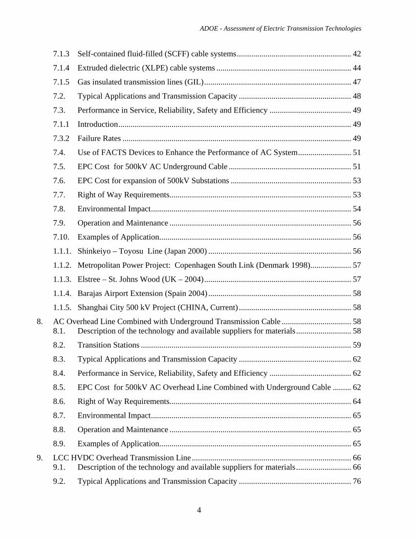
TABLE OF CONTENT: Executive Summary ........................................................................................................................... 7 1. Introduction.............................................................................................................................. 12 2. Purpose and Objectives............................................................................................................ 12 3. Background.............................................................................................................................. 12 4. Study Methodology.................................................................................................................. 12 5. Overview of Electric Transmission System Technologies ...................................................... 13 6. AC Overhead Transmission Line............................................................................................. 14
6.1. Description of the technology and available suppliers for materials........................... 14
6.1.1. Structures ..................................................................................................................... 15
6.1.2. Insulators...................................................................................................................... 16
6.1.3. Conductors ................................................................................................................... 17
6.2. Typical Applications and Transmission Capacity ....................................................... 19
6.2.1. Thermal Limit .............................................................................................................. 20
6.2.2. Voltage Constraints...................................................................................................... 20
6.2.3. Stability Constraints..................................................................................................... 20
6.3. Performance in Service, Reliability, Safety and Efficiency ........................................ 22
6.4. Use of FACTS Devices to Enhance the Performance of AC System.......................... 23
6.5. EPC Cost for 500kV AC Overhead Transmission Line ............................................. 30
6.6. EPC Cost for expansion of 500kV Substations ........................................................... 30
6.7. Right of Way Requirements......................................................................................... 33
6.8. Environmental Impact.................................................................................................. 34
6.9. Operation and Maintenance ......................................................................................... 40
6.10. Examples of Application.............................................................................................. 40
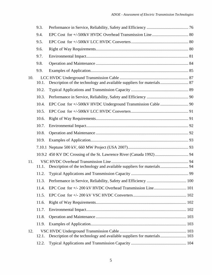
7. AC Underground Transmission Cable..................................................................................... 40 7.1. Description of the technology and available suppliers for materials (E)..................... 40
7.1.1 Introduction.................................................................................................................. 40
7.1.2 High-pressure fluid-filled (HPFF) pipe-type cable systems ........................................ 41
ADOE - Assessment of Electric Transmission Technologies
4
7.1.3 Self-contained fluid-filled (SCFF) cable systems........................................................ 42
7.1.4 Extruded dielectric (XLPE) cable systems .................................................................. 44
7.1.5 Gas insulated transmission lines (GIL)........................................................................ 47
7.2. Typical Applications and Transmission Capacity ....................................................... 48
7.3. Performance in Service, Reliability, Safety and Efficiency ........................................ 49
7.1.1 Introduction.................................................................................................................. 49
7.3.2 Failure Rates ................................................................................................................ 49
7.4. Use of FACTS Devices to Enhance the Performance of AC System.......................... 51
7.5. EPC Cost for 500kV AC Underground Cable ............................................................ 51
7.6. EPC Cost for expansion of 500kV Substations ........................................................... 53
7.7. Right of Way Requirements......................................................................................... 53
7.8. Environmental Impact.................................................................................................. 54
7.9. Operation and Maintenance ......................................................................................... 56
7.10. Examples of Application.............................................................................................. 56
1.1.1. Shinkeiyo – Toyosu Line (Japan 2000) ...................................................................... 56
1.1.2. Metropolitan Power Project: Copenhagen South Link (Denmark 1998).................... 57
1.1.3. Elstree – St. Johns Wood (UK – 2004)........................................................................ 57
1.1.4. Barajas Airport Extension (Spain 2004) ...................................................................... 58
1.1.5. Shanghai City 500 kV Project (CHINA, Current) ....................................................... 58
8. AC Overhead Line Combined with Underground Transmission Cable .................................. 58 8.1. Description of the technology and available suppliers for materials........................... 58
8.2. Transition Stations ....................................................................................................... 59
8.3. Typical Applications and Transmission Capacity ....................................................... 62
8.4. Performance in Service, Reliability, Safety and Efficiency ........................................ 62
8.5. EPC Cost for 500kV AC Overhead Line Combined with Underground Cable ......... 62
8.6. Right of Way Requirements......................................................................................... 64
8.7. Environmental Impact.................................................................................................. 65
8.8. Operation and Maintenance ......................................................................................... 65
8.9. Examples of Application.............................................................................................. 65
9. LCC HVDC Overhead Transmission Line .............................................................................. 66 9.1. Description of the technology and available suppliers for materials........................... 66
9.2. Typical Applications and Transmission Capacity ....................................................... 76
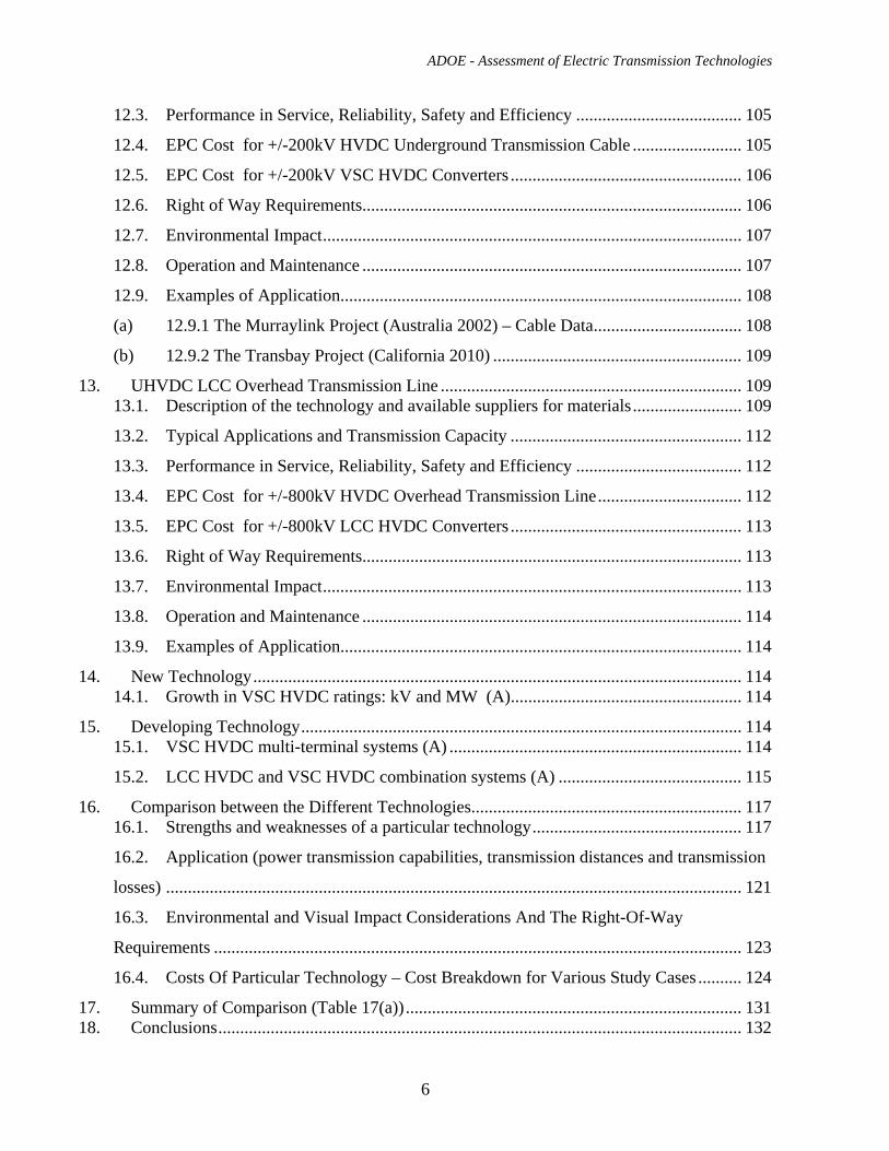
ADOE - Assessment of Electric Transmission Technologies
5
9.3. Performance in Service, Reliability, Safety and Efficiency ........................................ 76
9.4. EPC Cost for +/-500kV HVDC Overhead Transmission Line................................... 80
9.5. EPC Cost for +/-500kV LCC HVDC Converters ....................................................... 80
9.6. Right of Way Requirements......................................................................................... 80
9.7. Environmental Impact.................................................................................................. 81
9.8. Operation and Maintenance ......................................................................................... 84
9.9. Examples of Application.............................................................................................. 85
10. LCC HVDC Underground Transmission Cable .................................................................. 87 10.1. Description of the technology and available suppliers for materials........................... 87
10.2. Typical Applications and Transmission Capacity ....................................................... 89
10.3. Performance in Service, Reliability, Safety and Efficiency ........................................ 90
10.4. EPC Cost for +/-500kV HVDC Underground Transmission Cable ........................... 90
10.5. EPC Cost for +/-500kV LCC HVDC Converters ....................................................... 91
10.6. Right of Way Requirements......................................................................................... 91
10.7. Environmental Impact.................................................................................................. 92
10.8. Operation and Maintenance ......................................................................................... 92
10.9. Examples of Application.............................................................................................. 93
7.10.1 Neptune 500 kV, 660 MW Project (USA 2007).......................................................... 93
10.9.2 450 KV DC Crossing of the St. Lawrence River (Canada 1992) ................................ 94
11. VSC HVDC Overhead Transmission Line .......................................................................... 94 11.1. Description of the technology and available suppliers for materials........................... 94
11.2. Typical Applications and Transmission Capacity ....................................................... 99
11.3. Performance in Service, Reliability, Safety and Efficiency ...................................... 100
11.4. EPC Cost for +/- 200 kV HVDC Overhead Transmission Line............................... 101
11.5. EPC Cost for +/- 200 kV VSC HVDC Converters ................................................... 102
11.6. Right of Way Requirements....................................................................................... 102
11.7. Environmental Impact................................................................................................ 102
11.8. Operation and Maintenance ....................................................................................... 103
11.9. Examples of Application............................................................................................ 103
12. VSC HVDC Underground Transmission Cable ................................................................ 103 12.1. Description of the technology and available suppliers for materials......................... 103
12.2. Typical Applications and Transmission Capacity ..................................................... 104
ADOE - Assessment of Electric Transmission Technologies
6
12.3. Performance in Service, Reliability, Safety and Efficiency ...................................... 105
12.4. EPC Cost for +/-200kV HVDC Underground Transmission Cable ......................... 105
12.5. EPC Cost for +/-200kV VSC HVDC Converters ..................................................... 106
12.6. Right of Way Requirements....................................................................................... 106
12.7. Environmental Impact................................................................................................ 107
12.8. Operation and Maintenance ....................................................................................... 107
12.9. Examples of Application............................................................................................ 108
(a) 12.9.1 The Murraylink Project (Australia 2002) – Cable Data.................................. 108
(b) 12.9.2 The Transbay Project (California 2010) ......................................................... 109
13. UHVDC LCC Overhead Transmission Line ..................................................................... 109 13.1. Description of the technology and available suppliers for materials......................... 109
13.2. Typical Applications and Transmission Capacity ..................................................... 112
13.3. Performance in Service, Reliability, Safety and Efficiency ...................................... 112
13.4. EPC Cost for +/-800kV HVDC Overhead Transmission Line................................. 112
13.5. EPC Cost for +/-800kV LCC HVDC Converters ..................................................... 113
13.6. Right of Way Requirements....................................................................................... 113
13.7. Environmental Impact................................................................................................ 113
13.8. Operation and Maintenance ....................................................................................... 114
13.9. Examples of Application............................................................................................ 114
14. New Technology................................................................................................................ 114 14.1. Growth in VSC HVDC ratings: kV and MW (A)..................................................... 114
15. Developing Technology..................................................................................................... 114 15.1. VSC HVDC multi-terminal systems (A) ................................................................... 114
15.2. LCC HVDC and VSC HVDC combination systems (A) .......................................... 115
16. Comparison between the Different Technologies.............................................................. 117 16.1. Strengths and weaknesses of a particular technology................................................ 117
16.2. Application (power transmission capabilities, transmission distances and transmission
losses) .................................................................................................................................... 121
16.3. Environmental and Visual Impact Considerations And The Right-Of-Way
Requirements ......................................................................................................................... 123
16.4. Costs Of Particular Technology – Cost Breakdown for Various Study Cases .......... 124
17. Summary of Comparison (Table 17(a))............................................................................. 131 18. Conclusions........................................................................................................................ 132
ADOE - Assessment of Electric Transmission Technologies
7
Executive Summary “Assessment and Analysis of the State-Of-the-Art Electric Transmission Systems with Specific Focus on High-Voltage Direct Current (HVDC), Underground or Other New or Developing Technologies” prepared by Stantec. At the request of the Alberta Department of Energy, Stantec, Areva and Power Delivery Consultants prepared a “state-of-the-art study” comparing electric power transmission systems. In this study1 the following technologies have been compared: • conventional overhead High Voltage Alternating Current (HVAC) transmission lines to • underground HVAC transmission cables to • High Voltage Direct Current (HVDC) systems to • new and developing technologies Available Technologies The alternatives for large power transmission projects in Alberta are HVAC or HVDC technology carried primarily on overhead transmission lines and under limited situations underground transmission cables. HVAC Transmission Lines and Cables HVAC transmission lines are the predominant type used in North America for bulk transmission of electrical power. These transmission lines have been designed and constructed using: 1. Conventional over-head transmission lines using insulators and aluminum conductors
(bundles) with either (or a combination) of steel lattice towers, steel poles, or wood poles 2. A combination of both overhead transmission lines and underground transmission cables 500 kV AC Overhead Transmission Line (Conventional Construction) To date within Alberta all 500 kV transmission lines are HVAC lines, constructed with conventional steel lattice towers, insulators and wire. This is the most common construction method for short to medium length transmission lines and is a proven technology that provides 500 kV AC overhead transmission lines at a lower cost than other alternatives. The use of a reactive power compensator or flexible AC transmission system (FACTS) technologies may be required at medium transmission distances to meet reactive power requirements. A double circuit overhead transmission line has two circuits installed on the same towers that double the transmission capacity. This method uses a slightly wider right-of-way than a single circuit line but require slightly higher towers. The installed cost for the double circuit line is less than two single circuit lines.
1 Prices provided in the report are indicative only and are based on numerous assumptions. Actual costs would be application specific and based on the detailed design and according to the numerous design criteria decisions. For illustrative purposes the report provides a summary for 50 km, 100 km, 300, and/or 600 km power transmission schemes. The prices provided do not include land costs, as these are variable throughout the province. Detailed electrical modeling studies or simulations are required to verify the application of various types of high voltage apparatus or technology and their configuration within existing electrical networks. These simulations are required in order to determine how the electrical system will “behave” and if it will operate in a stable and predictable manner. These electrical modeling studies are beyond the scope of this report.
ADOE - Assessment of Electric Transmission Technologies
8
500 kV AC Underground Transmission Cable Alberta does not have any 500 kV AC underground transmission cable installations. Currently there are only a few 240 kV cables, which are the highest underground cable voltage installed in the province. These 240 kV cable installations pass through densely populated commercial and urban areas of cities where there is no available right-of-way for an overhead transmission line. One of these underground installations is EPCOR’s Downtown Edmonton Supply and Substation (DESS). This is a single circuit 240 kV underground cable installation, approximately 10 km in length that runs between Castledowns Substation in north Edmonton to the Victoria Terminal Substation near downtown Edmonton. This 240 kV underground cable installation passes through densely populated residential and commercial areas of Edmonton. The technology for manufacturing 500 kV underground cables and their associated splices are a relatively recent development in the transmission industry. The first installation of a 500 kV Cross-linked polyethylene (XLPE) cable complete with splices was done in Tokyo (Shinkeiyo – Toyosu), Japan. It is currently the longest 500 kV AC underground cable in the world and is installed in a tunnel (i.e. not buried nor installed in a duct bank system). This line is about 40 km in length and has shunt reactors at its ends. Underground HVAC cable transmission lines have been built in areas that require special considerations with limited right-of-ways for overhead transmission. For longer transmission distances the aggregate cost of HVAC underground cable lines and associated reactive power compensation equipment becomes very expensive. The following is a list of important design considerations when selecting a 500 kV underground cable installation: • In order to maintain system reliability, the number of underground cables required are double
the number of bundles for an overhead line. One single circuit 500 kV AC overhead transmission line (3 bundles of conductors) needs to be converted into two underground cable circuits (6 cables). In the event of a cable failure, the repair time can take up to 2 months and longer during cold weather. Since a 500 kV underground cable is a key transmission element and a two month outage cannot be tolerated, two underground cable circuits are required for a single circuit overhead transmission line. This adds significant costs to an underground cable installation for transmission capacities exceeding 2,000 MW. Some examples of installations that have two underground cable circuits are: o Lacenby to Shipton (UK) o Turbigo to Rho (Italy) o Aarhus to Aalborg (Denmark)
• A double circuit 500 kV AC overhead transmission line (6 bundles of conductors) can be converted into 12 underground cables, 100% redundancy for reliability
• Alternating Current (AC) may require special reactor stations every 10 to 30 km • The cable line may be constructed in a tunnel, duct or a trench When comparing the relative cost, underground construction costs are much higher than those of conventional overhead construction. These costs may increase due to factors such as crossings of roads, pipelines or other structures, watercourses, or construction difficulties. Placing the lines deeper is not desirable, as it would decrease the amount of power the cables may carry due to increased heating of the cable. This will derate the cable installation, i.e. decrease the amount of
ADOE - Assessment of Electric Transmission Technologies
9
electrical power flowing through the cable. There are very few 500 kV underground installations in the world and none is over 40 km in length.
Combination of 500 kV AC Overhead Transmission Line with 500 kV AC Underground Transmission Section As previously described, in Alberta there are no 500 kV underground cable installations. However, at 240 kV AC there is one installation where part of the transmission line is overhead and another part is an underground cable: • Two overhead transmission lines, one starting at the Petrolia Substation the other starting at the
Ellerslie Substation, convert to underground cables at the Argyll Transfer Station. These underground cables then end at the Bellamy Terminal Station near downtown Edmonton
• Both of the 240 kV underground cables travel along the same route, where they pass through densely populated residential and commercial areas of Edmonton
These installations require large transition stations where the transmission line goes from overhead to underground and vice versa. HVDC Line Commutated Converter (LCC) with an Overhead Transmission Line HVDC LCC systems are specialized types of transmission systems. Their main application occurs when there is a requirement to transmit large quantities of power. The cost for an overhead HVDC transmission line is less than its HVAC counterpart; however, the costs are high for the converter stations. Converter stations can be built in stages reducing their initial cost. HVDC can be used where asynchronous systems have to be connected or for environmental reasons. It also provides the ability to control power flow. HVDC LCC with an Underground Transmission Cable Replacing the overhead line in the previous case with an underground cable has a marked increase in cost due to the cost of underground cable construction. Note that in our review the transmission capacity has been reduced from 3,000 MW to 2,000 MW as the cable technology for the higher rating does not currently exist. This limits its capacity and makes it very expensive. Currently there is no cable suitable for long HVDC underground lines with voltages close to 500kV and power transmission capacity in the range of 2000MW and above. (Mass Impregnated (MI) cables are not practical for underground lines and extruded polymer cable technology has not been developed to meet requirements for very high DC voltages). HVDC Voltage Source Converter (VSC) with an Overhead Transmission Line HVDC VSC systems are a new technology not in commercial operation to date with overhead transmission lines. The first application of VSC technology with an overhead transmission line is scheduled to be commissioned in 2010. Similar to the LCC, the main application of the VSC occurs when there is a requirement to transmit a relatively large quantity of power. Another similarity occurs with the cost for an overhead HVDC transmission line being significantly less than its HVAC counterpart; however, there is a high cost of the VSC converter stations at each end
ADOE - Assessment of Electric Transmission Technologies
10
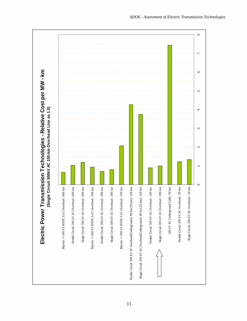
of the transmission line. The VSC has the added benefit that multi-terminal configurations are more readily achievable when compared to the HVDC LCC systems. At present, a HVDC overhead line with VSC true bipole converter is comparable to a HVDC overhead transmission line with conventional LCC converters for the lower range of transmission voltages and powers considered. It is expected that in the future HVDC VSC technologies will be used for overhead transmission voltages up to +/-640 kV for bipolar power ratings up to 2400MW. HVDC VSC with an Underground Transmission Cable Replacing the overhead line in the previous case with an underground cable increases the cost due to underground cable construction. Note that the cable technology for the higher ratings has not been developed. The HVDC cables with VSC converters currently in service can transmit relatively small amounts of power (in the range of 200 to 400 MW). This technology was used for the 180 km Murraylink in Australia. The manufacturers of this technology advise that in the near future HVDC VSC technology can be used for underground transmission at voltages up to +/-400kV and power levels up to 1500MW. Ultra High Voltage Direct Current (UHVDC) LCC with an Overhead Transmission Line The first application of this technology anywhere in the world has just been commissioned in China. The main application of the UHVDC LCC (+/- 800kV overhead transmission line and LCC converters) is when there is a requirement to transmit very large amounts of bulk power (up to 6,400 MW) over very long distances. This technology can only be applied in very large electrical transmission systems, where an outage of the UHVDC LCC system can be tolerated, without causing system stability problems. This technology would not be applicable within the Alberta system with its peak load of about 10,000 MW. One additional UHVDC project is in progress in China and there are plans for +/- 800kV transmission in India and South Africa as well. Similar schemes can be used in Canada and USA to connect remote power generation to load centers. Considering present power generation capacity and power requirements in Alberta, it is unlikely that such scheme will be required in the foreseeable future. The following page contains a chart with the summary results of cost estimates for transmission technologies considered in this report. More detailed results of the cost estimates are provided in the section 6.4 of the report.
ADOE - Assessment of Electric Transmission Technologies
11
Elec
tric
Pow
er T
rans
mis
sion
Tec
hnol
ogie
s - R
elat
ive
Cost
per
MW
- km
(Sin
gle
Circ
uit 5
00kV
AC
100-
km O
verh
ead
Line
as
1.0)
01
23
45
67
8
Sin
gle
Circ
uit 5
00 k
V A
C O
verh
ead
: 50
km
Dou
ble
Circ
uit 5
00 k
V A
C O
verh
ead
: 50
km
500
kV A
C U
nder
grou
nd C
able
: 50
km
Sin
gle
Circ
uit 5
00 k
V A
C O
verh
ead
: 100
km
Dou
ble
Circ
uit 5
00 k
V A
C O
verh
ead
: 100
km
Sing
le C
ircui
t 500
kV
AC
Ove
rhea
d/U
nder
grou
nd (
80 k
m/2
0 km
): 10
0 km
Dou
ble
Circ
uit 5
00 k
V A
C O
verh
ead/
Und
ergr
ound
( 80
km
/20
km):
100
km
Bip
olar
+/-5
00 k
V H
VDC
LCC
Ove
rhea
d : 1
00 k
m
Sin
gle
Circ
uit 5
00 k
V A
C O
verh
ead
: 300
km
Dou
ble
Circ
uit 5
00 k
V A
C O
verh
ead
: 300
km
Bip
olar
+/-5
00 k
V H
VDC
LCC
Ove
rhea
d : 3
00 k
m
Sin
gle
Circ
uit 5
00 k
V A
C O
verh
ead
: 600
km
Dou
ble
Circ
uit 5
00 k
V A
C O
verh
ead
: 600
km
Bip
olar
+/-5
00 k
V H
VDC
LCC
Ove
rhea
d : 6
00 k
m
ADOE - Assessment of Electric Transmission Technologies
12
1. Introduction The Alberta Department of Energy (ADOE) has employed Stantec Consulting Limited (Stantec) to provide an assessment and analysis, of the state–of–the–art in the electric power transmission systems. The specific focus of this study will be on high voltage direct current (HVDC), high voltage underground cables or other new or developing technologies. Stantec joined forces with AREVA T&D and Power Delivery Consultants (PDC) as their sub-consultants so that each organization could bring relevant expertise to this report. ABB and Siemens AG Energy Sector have been contacted as well. Their response and technical information are included in Appendix A and Appendix B.
2. Purpose and Objectives As requested by the ADOE the purpose of this report is to provide factual information with respect to the various power transmission system alternatives that may be used anywhere in Alberta. The overall objective is to understand whether there are economic and practical power system solutions that may reduce the impact of conventional overhead high voltage towers and wires.
3. Background In recent years Alberta has experienced a rapid increase in the demand for electric energy, however no significant high voltage transmission line projects have been built in the last 20 years. In order to maintain the reliability of electric transmission system, to sustain economic growth, to enable efficient use of renewable energy, to reduce land use impacts and to minimize energy losses several high voltage transmission projects are required throughout Alberta. Some of these facilities will be located near urban areas and on private land. Some stakeholders have expressed their concerns regarding the impact of these high voltage towers and lines and have proposed that underground construction for transmission lines be used instead. In order to review this alternative, the Alberta Government requires information and data on utilizing these new or developing electric power technologies including the use of high voltage underground transmission cables.
4. Study Methodology In this report, we will investigate all currently available technologies for the transmission of electric power and also technologies that may be available in the near future. The strengths, weaknesses and main characteristics of each technology will be described along with how the technology can be applied. The following points will be addressed:
Power transmission capabilities (MW), and the available voltage Optimal length of a transmission line or cable for each technology Specific issues with each type of technology Environmental concerns for each technology Cost comparison between the various technologies
ADOE - Assessment of Electric Transmission Technologies
13
Reliability, efficiency, performance, and operational features for each technology
Then the findings on these different technologies will be compared and summarized.
5. Overview of Electric Transmission System Technologies The electric power transmission system is a network of high voltage transmission lines and substations that connect remote power plants with substations near populated areas or loads. In order to reduce the power losses over long distances the electricity is transmitted at high voltage. Near the consumers or loads the electricity is transformed back down to medium and then to low voltages for consumption. The vast majority of electric energy in Alberta is transmitted as alternating current (AC) through aluminum conductors. In AC systems the flow of electric charge periodically reverses direction. One of the main advantages of an AC system is that using a power transformer, it can easily be transformed from low to high voltage and vice versa. Where a large amount of power has to be transmitted, high voltage direct current (HVDC) can be a suitable solution. There are many other reasons why HVDC is selected, such as frequency conversion, connecting asynchronous systems (for example, the McNeill back to back station between Alberta and Saskatchewan), controllability, expandability, less right-of-way and submarine cable crossings. Direct current is the flow of electric charge in one direction only (there is no reversal of the direction of charge as seen in AC systems). At the transmitting and receiving ends of a HVDC transmission line or cable, the converter stations “convert” direct current back into alternating current and vice versa, where it can be distributed for consumption by conventional AC distribution systems. In an electric transmission line (either AC or DC), the electric current flows through insulated metal conductors (typically aluminum) and the power is transmitted through the electric and magnetic fields around these conductors. In an overhead transmission line the surrounding air is used as an insulating medium, between the conductor and the ground. Porcelain, glass or polymer insulator units are then used to support and insulate the live conductors from the transmission line structure. In densely populated urban areas transmission of electric power by underground power cables is becoming more common. The metal conductors in power cables are fully surrounded by an insulating medium, usually oil and paper or polymers such as polyethylene or cross linked polyethylene. In specific applications, very short transmission lines can be constructed using pressurized SF6 gas as the insulating medium. These gas insulated transmission lines consist of an inner aluminum conductor tube, supported by insulating spacer rings that are attached to an outer aluminum sheath tube. This type of pressurized SF6 construction is limited in its application because of the capital, operating and maintenance costs.
ADOE - Assessment of Electric Transmission Technologies
14
Power cables with high temperature superconducting (HTS) wires are also being used in commercial power delivery networks. A liquid nitrogen refrigeration system is used to keep the temperature of HTS wires below their superconducting transition temperature. It is expected that in the foreseeable future the use of HTS cables will remain limited to very special applications such as Long Island (NY), Soul (S. Korea), etc, where the land costs and other limitations prohibit the use of more conventional technologies. To date, the maximum length of any of the installed HTS systems is less than 1 km and they were really research and development projects with high government subsidies. The electric power technologies mentioned above are based on metal conductors connecting a power or generating source to an electrical load. Wireless power transmission based on the same physical principles as those used in telecommunications and broadcasting industries are also possible. This type of wireless power transmission is accomplished by using electromagnetic induction, microwaves or lasers. The three main requirements of a power transmission system, namely the: (1) large amount of power to be transmitted, (2) the long transmission distance between generation and load, and (3) the high efficiency requirement for a commercial installation (low losses) make these types of technology not practical for a commercial bulk power transmission system applications. Keeping in mind the specific local conditions, it is clear that at this time only four electric power technologies can be considered for application in Alberta:
- AC Overhead Transmission Lines - AC Underground Cables - HVDC Overhead Transmission Lines - HVDC Underground Cables
6. AC Overhead Transmission Line
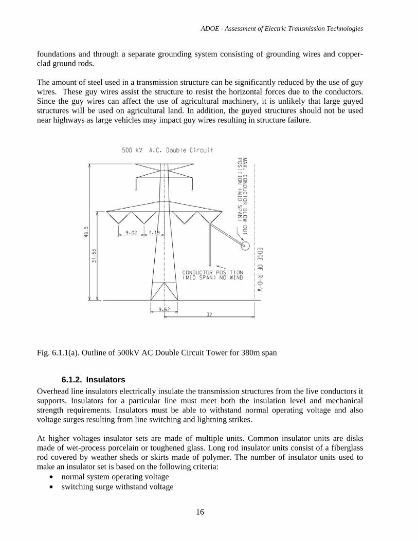
6.1. Description of the technology and available suppliers for materials An alternating current overhead transmission circuit consists of a three-phase system of bare conductors suspended by a series of transmission structures. Each phase typically consists of one, two, three or four conductors. At the suspension points or structures the phases are insulated from each other and from the ground by means of insulators. In the mid-span between the structures the phase conductors are insulated by air. Transmission structures usually support one or two circuits (three or six phases) which are described as either a “single circuit” or a “double circuit” line, respectively. Each three-phase circuit acts as one system providing full path for the currents, i.e. one phase returns the sum of the currents sent by other two phases. The voltages and currents of each phase periodically change direction and intensity. Typical outline for a 500 kV single circuit and double circuit transmission structure are shown in Fig. 16.3(a) and Fig. 6.1.1(a). In Alberta 69/72kV, 138/144 kV, 240 kV and 500kV are the transmission voltages used. These represent the phase-to-phase nominal voltages. The corresponding phase-to-ground voltages are
ADOE - Assessment of Electric Transmission Technologies
15
1.73 times less. The power transmitted is expressed in megawatts (MW) and quantifies the power transmitted by one circuit (three phases). The main components of a transmission line are:
6.1.1. Structures The purpose of a transmission structure is to keep the high voltage phase conductors away from their surroundings and from each other. For lower voltages (69/72 kV, 138/144 kV and some 240 kV lines), structures may be constructed by using wood poles. Wood H-frame structures are common for single circuit 138/240 kV lines in Alberta. However, for higher voltages (240 kV and higher) structures are typically made using steel tubular poles or lattice type steel towers. Depending on their duty within a transmission line, the following structure types are typically designed:
• Tangent or Suspension Type Structures • Strain Angle Type Structures • Dead-end Type Structures
Tangent or Suspension type structures are designed for the straight-line sections or small line angles and normally support the weight of conductors and insulators and transverse loads due to the effects of wind on conductors themselves. The outline of 500kV double circuit Tangent lattice steel tower is shown in Fig. 6.1.1(a). and the effect of wind can also be seen as “conductor blow out”. Strain Angle structures support the weight of the insulators and conductors, transverse loads due to conductors pull and wind on conductors, and longitudinal loads due to uneven ice load on conductors or failure (break) of one or more conductors. Dead-end structures are designed for line termination or for large angles. In addition to the loads described above, these structures can withstand the full pull of all conductors from one side of the structure, in the direction of the line. Wind loading on the structure itself is added to the conductors loadings. Extreme climatic loading and combination of weather loadings (wind, ice, snow, and temperature) are taken into account to create the various design loading cases. In Alberta, the extreme wind speed for 100-year return period will be adopted for 500 kV tower design. These lines will also be designed to withstand the combined wet snow and wind loads that are expected to occur (100-year return period). Structure strength data has been collected through years of load type tests. By the use of statistics and reliability based design methods, it is possible to design the transmission structures for the desired level of safety and reliability. This is especially true for latticed towers for which extensive load type tests data has been collected over the last 60 years, which shows good correlation with the design calculation predictions. Foundations for transmission structures are designed based on geotechnical investigations, and the most onerous combinations of structure loadings. Concrete footings are normally used for towers; and piled foundations are used in areas where ground conditions are poor. In order to keep the tower electrical potential low enough for the case of fault current flow and to protect the line insulation from lightning back-flash, each structure is grounded through its
ADOE - Assessment of Electric Transmission Technologies
16
foundations and through a separate grounding system consisting of grounding wires and copper-clad ground rods. The amount of steel used in a transmission structure can be significantly reduced by the use of guy wires. These guy wires assist the structure to resist the horizontal forces due to the conductors. Since the guy wires can affect the use of agricultural machinery, it is unlikely that large guyed structures will be used on agricultural land. In addition, the guyed structures should not be used near highways as large vehicles may impact guy wires resulting in structure failure.
Fig. 6.1.1(a). Outline of 500kV AC Double Circuit Tower for 380m span
6.1.2. Insulators Overhead line insulators electrically insulate the transmission structures from the live conductors it supports. Insulators for a particular line must meet both the insulation level and mechanical strength requirements. Insulators must be able to withstand normal operating voltage and also voltage surges resulting from line switching and lightning strikes. At higher voltages insulator sets are made of multiple units. Common insulator units are disks made of wet-process porcelain or toughened glass. Long rod insulator units consist of a fiberglass rod covered by weather sheds or skirts made of polymer. The number of insulator units used to make an insulator set is based on the following criteria:
• normal system operating voltage • switching surge withstand voltage
ADOE - Assessment of Electric Transmission Technologies
17
• lightning impulse withstand voltage • altitude and environmental factors such as pollution, fog, snow accumulation, and salt
accumulation in coastal areas Insulators for 500 kV normally have grading rings, which improve the electric field distribution along the insulator string, and also reduce corona emission. Corona is a partial electric discharge at points where electric field exceeds corona inception level (the electrical breakdown strength of air). Tension (dead –end) insulator sets hold the full pull of conductors. Suspension insulator sets hold only the vertical load resulting from the wind action and weight of the conductors.
6.1.3. Conductors The most critical decision in the design of a high voltage line is often the selection of the phase conductors, and shield wires. The overhead transmission line conductors are normally composed of strands of aluminum, an aluminum alloy or aluminum combined with one or more steel core wires. These conductor types are known as:
• all aluminum conductors (AAC) • all aluminum alloy conductors (AAAC) • aluminum conductors alloy reinforced (ACAR) • aluminum conductor steel reinforced (ACSR), (most commonly used in Alberta).
The operating temperature of these “conventional” conductors should not normally exceed 100 oC, or damage to the aluminum portion of the conductor may result (annealing). In addition to these conventional conductors a class of high temperature conductors capable of transmitting larger quantities of power using existing right-of–ways, has come into use over the last twenty years. Conductors like XTACSR and ACSS can operate at temperature of 230 oC and 250 oC respectively. Aluminum conductor composite core (ACCC) has a core of polymer–bound carbon-fibers encased in a fiberglass tube. The outer conductive part consists of trapezoidal shaped fully annealed aluminum wires and can operate at 200oC. A modified type of ACSR conductor, which uses trapezoidal shaped wires (rather than round wires), called ACSR/TW, is being used by a number of major utilities and is planned for use on some new lines in Alberta. The advantage of the trapezoidal strands is that it allows more aluminum to be placed in a conductor with the same outside diameter. Bundled conductors consist of several conductor cables connected by spacers. These bundled conductors are typically used for voltages above 240 kV, in order to reduce corona and audible noise. The tensions for conductors or bundled conductors are selected so that the loads on the structures and tensions in the conductors do not exceed the strength of the structures or the conductors themselves under ultimate design conditions. For code-mandated loadings (CAN/CSA-C22.3 N0. 1-06) the allowable tension in conductors is limited to 60% of the conductor ultimate strength. To match better the local conditions in Alberta and to provide an additional margin of safety, the maximum allowable tension in the conductors is limited to not more than 85% of the strength,
ADOE - Assessment of Electric Transmission Technologies
18
under the most severe loading case. Conductor tensions are also selected so as to avoid conductor damage due to vibration caused by low speed winds (aeolian vibration). The conductor sags are designed so that safe clearances to ground are maintained. Clearance must also be maintained when crossing over objects, or crossing over other transmission or distribution lines. In addition to the ground clearance, the phase to phase clearance must also be maintained between the conductors themselves under specified design conditions (wind, temperature, ice). Transmission line towers are usually taller than surrounding objects and they are a likely target for lightning strikes. This puts the conductors and other equipment on a transmission tower at risk. To control the effects of lightning, an extra set of wires is installed at the highest points of the tower. These wires are called shield wires and are either steel or aluminum-clad steel stranded wires with an overall diameter of approximately 13 mm. The shield wires provide a path for a lightning strike to travel directly to ground through the tower and into its grounding system. The shield wires provide protection for the live power conductors and to objects below or near the line. Available Suppliers The Alberta’s Transmission Facility Owners source materials worldwide. The major suppliers of materials of overhead transmission lines in Canada and North America are:
Steel Structures:
Valmont Newmark Lockweld Inc. SAE (in Mexico) Thomas & Betts Fabrimet Inc. Nova Pole Slacan Industries Inc, Falcon Steel Company
Insulators:
Seves (Sediver) Ohio Brass ( Hubbel Power Systems) Hubbel Power Systems NGK Locke, Inc. Lapp Insulator Company For porcelain, NGK (Japan) is acceptable and for glass, it is Seves. The other companies noted above may be acceptable for synthetic insulators.
Fittings and Hardware:
Slacan Industries Inc. Anderson (Hubbell Power Systems) Chance (Hubbell Power Systems) Tyco Electronics Corporation MacLean Power Systems
ADOE - Assessment of Electric Transmission Technologies
19
FCI - Burndy Products Preformed Line Products Lindsey Manufacturing Company
The fittings for 500kV transmission lines shall meet low temperature impact requirements. It cannot be confirmed at the moment that all companies listed above can meet that requirement. Conductors:
Southwire Company General Wire and Cable Alcan Cable CTC Cable Corporation Nexans Inc AFL Telecommunications 3M Electrical
6.2. Typical Applications and Transmission Capacity From the very beginning of electrical transmission, AC has been the leading technology in electrical networks. Its biggest advantage is in the use of transformers to convert low voltage- high current power into an equivalent high voltage - low current power. Transmission line losses are a direct function of the square of the transmitted current. For example, by halving the current, transmission loss becomes one quarter of its original value. Therefore, by transmitting at high voltage and low current, prohibitively expensive line losses are avoided and long distance power transmission is made possible. Wide area AC transmission grids form the basis of electric energy transfer systems worldwide.
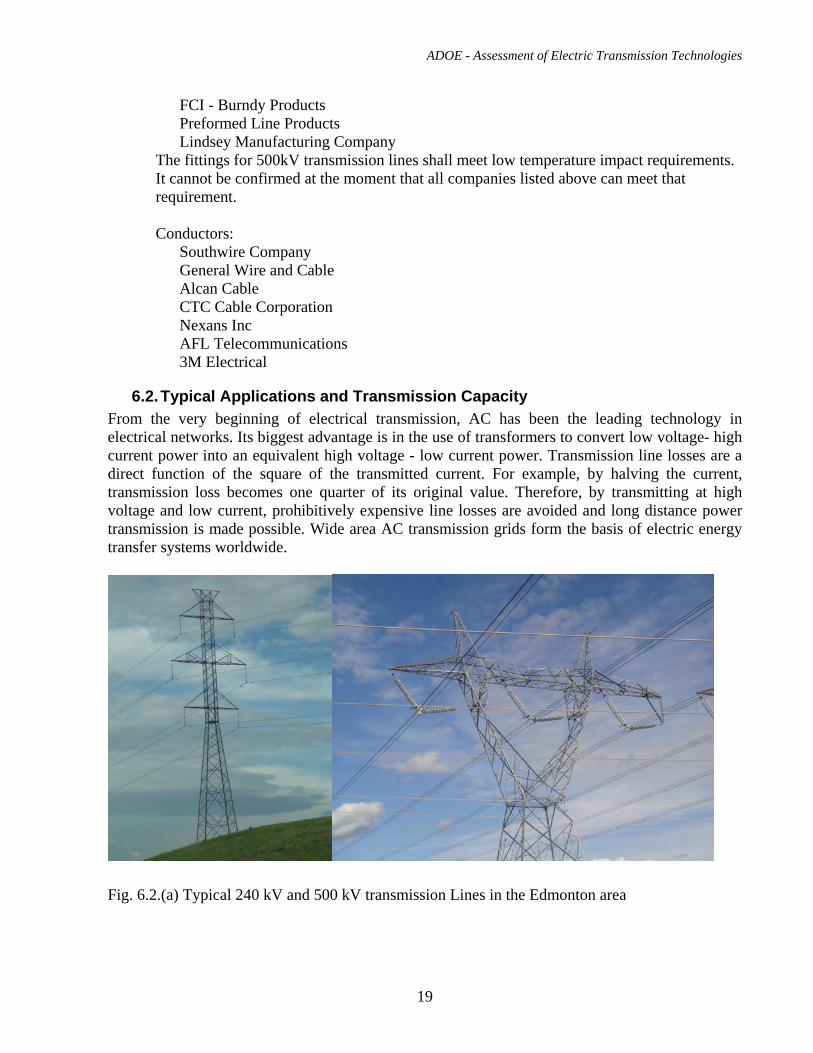
Fig. 6.2.(a) Typical 240 kV and 500 kV transmission Lines in the Edmonton area
ADOE - Assessment of Electric Transmission Technologies
20
The power transfer capacity of AC overhead transmission system is constrained by several factors. The most common constrains are explained below.
6.2.1. Thermal Limit Electric current passing through a conductor causes heating of the conductor. As the conductors’ temperature increases, the sag between the structures which supports the conductor increases. The sag of an overhead line conductor is designed under the assumption that a maximum allowable conductor temperature is not exceeded. This temperature limit is usually set to 100oC for normal ACSR conductors. If the current rating of the line is exceeded, it can increase the sag of the conductor to a point where it violates the specified ground clearances or the clearance to an object that it is crossing over. Also excessive conductor temperature may reduce the mechanical strength of the conductor and reduce its service life.
6.2.2. Voltage Constraints An AC transmission line can be represented as a ladder of series of resistances and inductances, connected in parallel with capacitors. Therefore, the variation in time of voltages and currents will lag each other. As a result, both active and reactive power will flow from the sending to the receiving end of a transmission line. Reactive power is a concept used to describe the behavior of an AC system which exchanges the power between inductors and capacitors. The inductor or capacitor stores electrical energy during one-fourth of an AC cycle, and returns it back to its source during the next quarter of the cycle. So, the part of the power that flows back and forth across the transmission line, which cannot be consumed is called “reactive power”. The rest of the power that flows from source to load can be consumed and it is called “real power”. The flow of reactive power back and forth leads to an extra current in the AC transmission line. This extra current causes extra heating of the line conductors and also causes a voltage drop. In addition to the heating caused by the reactive power flow, there is heating caused by current passing through the line resistance, due to active power flow. The power losses and voltage drop increase with the length of the line. The issue of managing the reactive power in AC systems by use of FACTS devices, is addressed in section 6.4. The large voltage drop or rise along the transmission line either above or below the nominal value may damage equipment or adversely affect the operation of the system. Therefore, both the amount of power (active and reactive) transmitted and the transmission line lengths are limited by voltage constraints.
6.2.3. Stability Constraints For long AC transmission lines system stability determines the limit with respect to the maximum power that can be transmitted. According to Alberta Electric System Operator (AESO) rules: “stability” is defined as the ability of an electric system to maintain a state of equilibrium and synchronism between its parts during normal and abnormal system conditions or disturbances.
ADOE - Assessment of Electric Transmission Technologies
21
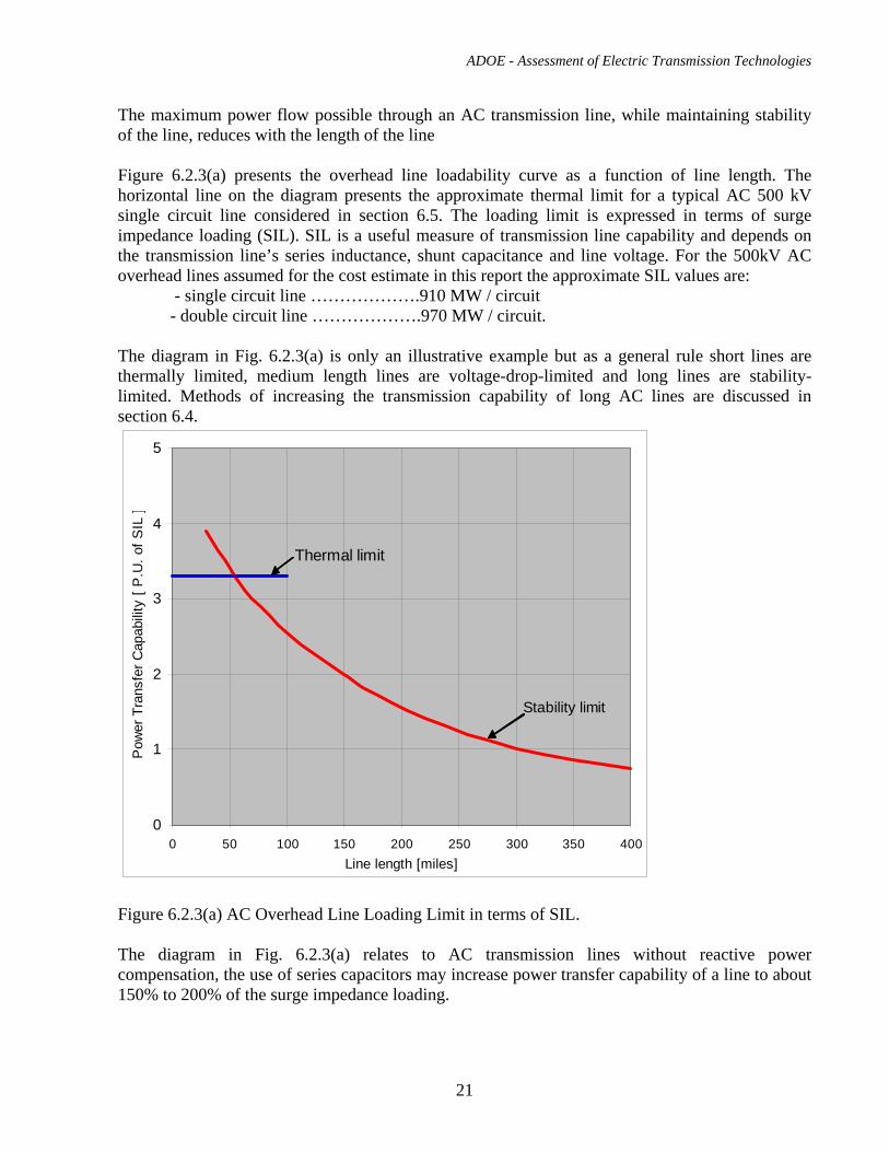
The maximum power flow possible through an AC transmission line, while maintaining stability of the line, reduces with the length of the line Figure 6.2.3(a) presents the overhead line loadability curve as a function of line length. The horizontal line on the diagram presents the approximate thermal limit for a typical AC 500 kV single circuit line considered in section 6.5. The loading limit is expressed in terms of surge impedance loading (SIL). SIL is a useful measure of transmission line capability and depends on the transmission line’s series inductance, shunt capacitance and line voltage. For the 500kV AC overhead lines assumed for the cost estimate in this report the approximate SIL values are: - single circuit line ……………….910 MW / circuit
- double circuit line ……………….970 MW / circuit. The diagram in Fig. 6.2.3(a) is only an illustrative example but as a general rule short lines are thermally limited, medium length lines are voltage-drop-limited and long lines are stability-limited. Methods of increasing the transmission capability of long AC lines are discussed in section 6.4.
Thermal limit
0
1
2
3
4
5
0 50 100 150 200 250 300 350 400Line length [miles]
Pow
er T
rans
fer C
apab
ility
[ P
.U. o
f SIL
]
Stability limit
Figure 6.2.3(a) AC Overhead Line Loading Limit in terms of SIL. The diagram in Fig. 6.2.3(a) relates to AC transmission lines without reactive power compensation, the use of series capacitors may increase power transfer capability of a line to about 150% to 200% of the surge impedance loading.
ADOE - Assessment of Electric Transmission Technologies
22
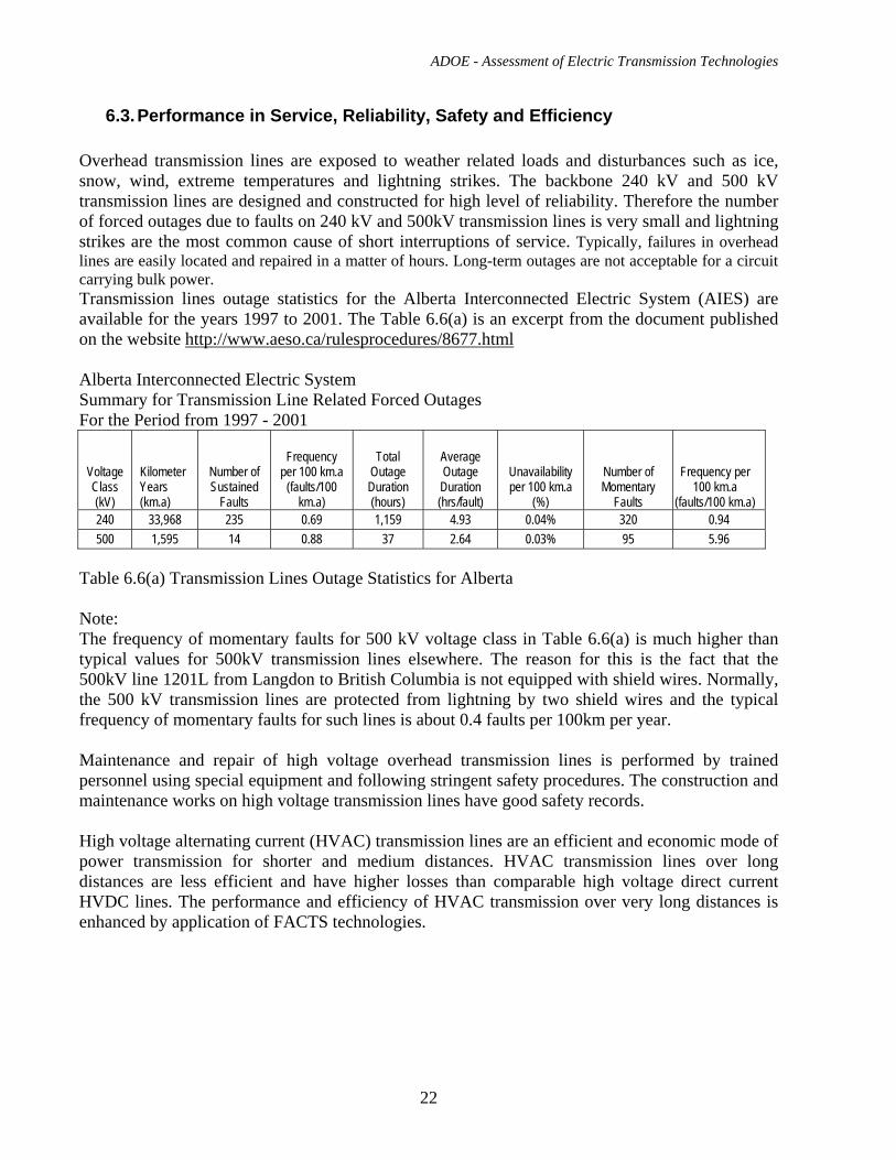
6.3. Performance in Service, Reliability, Safety and Efficiency Overhead transmission lines are exposed to weather related loads and disturbances such as ice, snow, wind, extreme temperatures and lightning strikes. The backbone 240 kV and 500 kV transmission lines are designed and constructed for high level of reliability. Therefore the number of forced outages due to faults on 240 kV and 500kV transmission lines is very small and lightning strikes are the most common cause of short interruptions of service. Typically, failures in overhead lines are easily located and repaired in a matter of hours. Long-term outages are not acceptable for a circuit carrying bulk power. Transmission lines outage statistics for the Alberta Interconnected Electric System (AIES) are available for the years 1997 to 2001. The Table 6.6(a) is an excerpt from the document published on the website http://www.aeso.ca/rulesprocedures/8677.html Alberta Interconnected Electric System Summary for Transmission Line Related Forced Outages For the Period from 1997 - 2001
Voltage Class (kV)
Kilometer Years (km.a)
Number of Sustained
Faults
Frequency per 100 km.a
(faults/100 km.a)
Total Outage Duration (hours)
Average Outage Duration (hrs/fault)
Unavailability per 100 km.a
(%)
Number of Momentary
Faults
Frequency per 100 km.a
(faults/100 km.a) 240 33,968 235 0.69 1,159 4.93 0.04% 320 0.94 500 1,595 14 0.88 37 2.64 0.03% 95 5.96
Table 6.6(a) Transmission Lines Outage Statistics for Alberta Note: The frequency of momentary faults for 500 kV voltage class in Table 6.6(a) is much higher than typical values for 500kV transmission lines elsewhere. The reason for this is the fact that the 500kV line 1201L from Langdon to British Columbia is not equipped with shield wires. Normally, the 500 kV transmission lines are protected from lightning by two shield wires and the typical frequency of momentary faults for such lines is about 0.4 faults per 100km per year. Maintenance and repair of high voltage overhead transmission lines is performed by trained personnel using special equipment and following stringent safety procedures. The construction and maintenance works on high voltage transmission lines have good safety records. High voltage alternating current (HVAC) transmission lines are an efficient and economic mode of power transmission for shorter and medium distances. HVAC transmission lines over long distances are less efficient and have higher losses than comparable high voltage direct current HVDC lines. The performance and efficiency of HVAC transmission over very long distances is enhanced by application of FACTS technologies.
ADOE - Assessment of Electric Transmission Technologies
23
6.4. Use of FACTS Devices to Enhance the Performance of AC System
In theory, an AC transmission system should be able to carry power up to its thermal design limits. However, the AC transmission system becomes constrained to ratings which are often well below its thermal limit. These constraints are mostly caused by reactive power (measured in MVAr – Millions of Volt Amp reactive), as most loads consume reactive power as well as active (real) power. The AC transmission (and distribution) system itself both consumes and produces reactive power – due to the capacitances and inductances of transformers, overhead lines and/or cables that are always used.
An excess of reactive power will lead to overvoltages, too little reactive power will cause undervoltages – both can lead to a supply voltage at consumers which is not within contractual limits or even line tripping. Therefore, a reactive power balance has to be maintained, both statically and dynamically, throughout an AC transmission network for security of supply.
Consequently, for security, an AC transmission operator may wish to install some form of reactive power compensation at one or several points in the system. Power electronics based reactive power compensators are classically called FACTS (Flexible AC Transmission Systems).
FACTS are able to maintain a tightly controlled voltage profile along, and at the receiving end, of a line under many network operating conditions, static and dynamic – leading to an increased transfer of real power along the line. This is particularly relevant for long lines which naturally have high inductances and capacitances, and without FACTS the voltage supplied to consumers would be a long way out of contractual limits, except under very few operational conditions.
FACTS are also able to increase the dynamic stability of an AC transmission line by being able to react quickly to provide the necessary reactive power compensation for the transients that occur during and after fault situations.
FACTS devices exist in two distinct categories:
• Shunt connected, with the two major devices being: • SVC (Static VAr Compensator) • STATCOM (Static Synchronous Compensator)
• Series connected, with the two main systems being:
• FSC (Fixed Capacitor Series Compensator) • TCSC (Thyristor Controlled Series Compensator)
Series compensation can sometimes be used in conjunction with shunt compensation for optimal improvement.
Other series FACTS devices do exist, for example the SSSC (Static Synchronous Series Compensator), but are not described in this document, as they have only been installed at experimental sites to date.
ADOE - Assessment of Electric Transmission Technologies
24
The choice of the appropriate FACTS type, its optimum rating and the location in the network where equipment is to be installed, is determined by a system study taking into account all known loads, possible fault conditions and the requirements (MVAr and time) for recovery to take place.
All FACTS device types can be installed at the appropriate point in new AC transmission lines as they are being constructed or can be added to the lines as required at a future date(s).
Shunt Connected Systems
These systems operate by sensing the AC line voltage and linearly increase their inductance (and at the same time reduce their capacitance) to reduce the AC line voltage or linearly decrease their inductance (and at the same time increase their capacitance) to increase the AC line voltage. These increases/decreases can be achieved very dynamically in order to quickly react to changes in the AC line to maintain stability.
SVC (Static VAr Compensator)
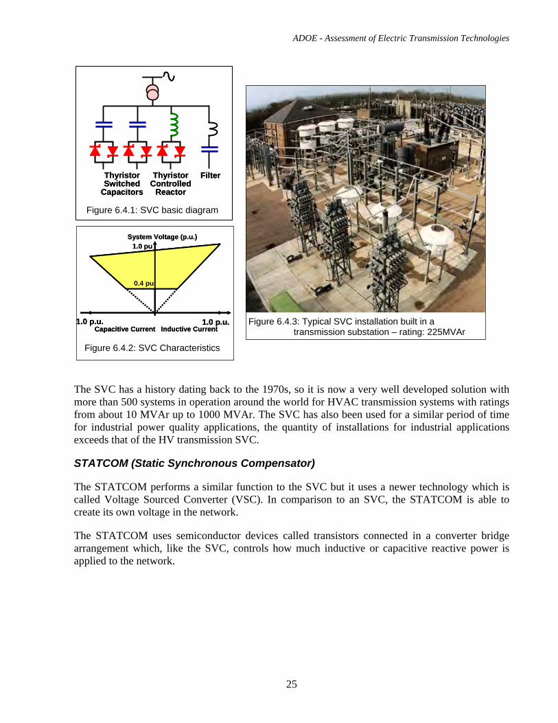
The SVC uses semiconductor devices, called thyristors, to control how much inductive and capacitive reactive power is applied to the network. A filter will also be used to prevent any harmonic distortion being injected into the line. The process is called line commutation which means that a network voltage must be present otherwise the SVC will not function. The basic single line diagram of an SVC is shown in Figure 6.4.1, the operational characteristics for an SVC are shown in Figure 6.4.2 and a typical SVC installation built in a Transmission sub-station is shown in Figure 6.4.3.
ADOE - Assessment of Electric Transmission Technologies
25
The SVC has a history dating back to the 1970s, so it is now a very well developed solution with more than 500 systems in operation around the world for HVAC transmission systems with ratings from about 10 MVAr up to 1000 MVAr. The SVC has also been used for a similar period of time for industrial power quality applications, the quantity of installations for industrial applications exceeds that of the HV transmission SVC.
STATCOM (Static Synchronous Compensator)
The STATCOM performs a similar function to the SVC but it uses a newer technology which is called Voltage Sourced Converter (VSC). In comparison to an SVC, the STATCOM is able to create its own voltage in the network.
The STATCOM uses semiconductor devices called transistors connected in a converter bridge arrangement which, like the SVC, controls how much inductive or capacitive reactive power is applied to the network.
Thyristor Controlled
Reactor
Thyristor Switched
Capacitors
FilterThyristor Controlled
Reactor
Thyristor Switched
Capacitors
Filter
Figure 6.4.1: SVC basic diagram
Capacitive Current Inductive Current
System Voltage (p.u.)
1.0 p.u. 1.0 p.u.
1.0 pu
0.4 pu
Capacitive Current Inductive Current
System Voltage (p.u.)
1.0 p.u. 1.0 p.u.
1.0 pu
0.4 pu
Figure 6.4.2: SVC Characteristics
Figure 6.4.3: Typical SVC installation built in a transmission substation – rating: 225MVAr
ADOE - Assessment of Electric Transmission Technologies
26
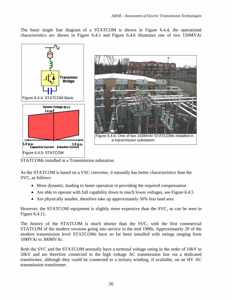
The basic single line diagram of a STATCOM is shown in Figure 6.4.4, the operational characteristics are shown in Figure 6.4.5 and Figure 6.4.6 illustrates one of two 150MVAr
STATCOMs installed in a Transmission substation.
As the STATCOM is based on a VSC converter, it naturally has better characteristics than the SVC, as follows:
• More dynamic, leading to faster operation in providing the required compensation • Are able to operate with full capability down to much lower voltages, see Figure 6.4.5 • Are physically smaller, therefore take up approximately 50% less land area
However, the STATCOM equipment is slightly more expensive than the SVC, as can be seen in Figure 6.4.11.
The history of the STATCOM is much shorter than the SVC, with the first commercial STATCOM of the modern versions going into service in the mid 1990s. Approximately 20 of the modern transmission level STATCOMs have so far been installed with ratings ranging from 10MVAr to 300MVAr.
Both the SVC and the STATCOM normally have a terminal voltage rating in the order of 10kV to 50kV and are therefore connected to the high voltage AC transmission line via a dedicated transformer, although they could be connected to a tertiary winding, if available, on an HV AC transmission transformer.
Transistor Bridge
Transistor Bridge
Figure 6.4.4: STATCOM Basic
Figure 6.4.5: STATCOM Capacitive Current Inductive Current
System Voltage (p.u.)
1.0 p.u. 1.0 p.u.
1.0 pu
Capacitive Current Inductive Current
System Voltage (p.u.)
1.0 p.u. 1.0 p.u.
1.0 pu
Figure 6.4.6: One of two 150MVAr STATCOMs installed in a transmission substation
ADOE - Assessment of Electric Transmission Technologies
27
Series Connected Systems
Series connected systems involve connecting capacitance in series with the transmission line. This series capacitor effectively cancels part of the line inductance to reduce the transfer impedance of the line which in turn significantly increases the power transfer capacity of the line. Additionally the series capacitor system can:
• Control the sharing of power between parallel connected lines • Provide reactive power to the circuit • Maintain the phase angle across transmission line within safe limits to ensure angular
stability • Enhanced voltage stability along the line
The series connected systems have to be built on platforms insulated at the voltage level of the transmission line itself.
If power electronics are used in association with the series capacitance (see TCSC) then the system can act fast enough to provide damping of power oscillations to improve voltage stability and prevent sub-synchronous resonance, which could cause damage to the shafts of any locally connected generators.
The simplest form of series compensation is known as fixed series compensation (FSC), the main benefit of which is to allow an increase in transmission capacity. The more sophisticated TCSC (thyristor controlled series compensation) is deployed if fast control of the line impedance is required for load-flow control and for damping power oscillations. It also has the benefit of enabling the mitigation of sub-synchronous resonances.
FSC (Fixed Capacitor Series Compensator)
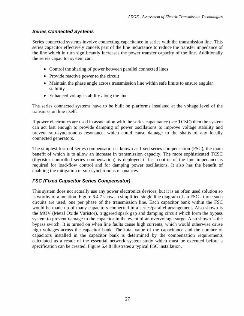
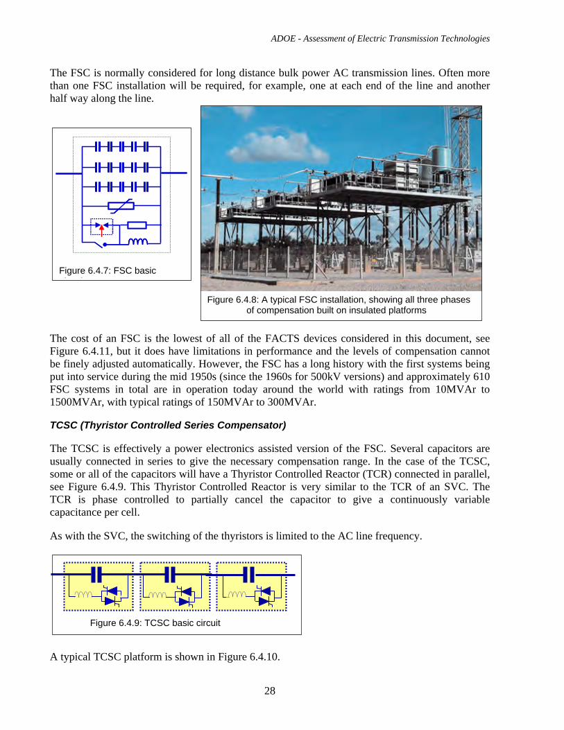
This system does not actually use any power electronics devices, but it is an often used solution so is worthy of a mention. Figure 6.4.7 shows a simplified single line diagram of an FSC - three such circuits are used, one per phase of the transmission line. Each capacitor bank within the FSC would be made up of many capacitors connected in a series/parallel arrangement. Also shown is the MOV (Metal Oxide Varistor), triggered spark gap and damping circuit which form the bypass system to prevent damage to the capacitor in the event of an overvoltage surge. Also shown is the bypass switch. It is turned on when line faults cause high currents, which would otherwise cause high voltages across the capacitor bank. The total value of the capacitance and the number of capacitors installed in the capacitor bank is determined by the compensation requirements calculated as a result of the essential network system study which must be executed before a specification can be created. Figure 6.4.8 illustrates a typical FSC installation.
ADOE - Assessment of Electric Transmission Technologies
28
The FSC is normally considered for long distance bulk power AC transmission lines. Often more than one FSC installation will be required, for example, one at each end of the line and another half way along the line.
The cost of an FSC is the lowest of all of the FACTS devices considered in this document, see Figure 6.4.11, but it does have limitations in performance and the levels of compensation cannot be finely adjusted automatically. However, the FSC has a long history with the first systems being put into service during the mid 1950s (since the 1960s for 500kV versions) and approximately 610 FSC systems in total are in operation today around the world with ratings from 10MVAr to 1500MVAr, with typical ratings of 150MVAr to 300MVAr.
TCSC (Thyristor Controlled Series Compensator)
The TCSC is effectively a power electronics assisted version of the FSC. Several capacitors are usually connected in series to give the necessary compensation range. In the case of the TCSC, some or all of the capacitors will have a Thyristor Controlled Reactor (TCR) connected in parallel, see Figure 6.4.9. This Thyristor Controlled Reactor is very similar to the TCR of an SVC. The TCR is phase controlled to partially cancel the capacitor to give a continuously variable capacitance per cell.
As with the SVC, the switching of the thyristors is limited to the AC line frequency.
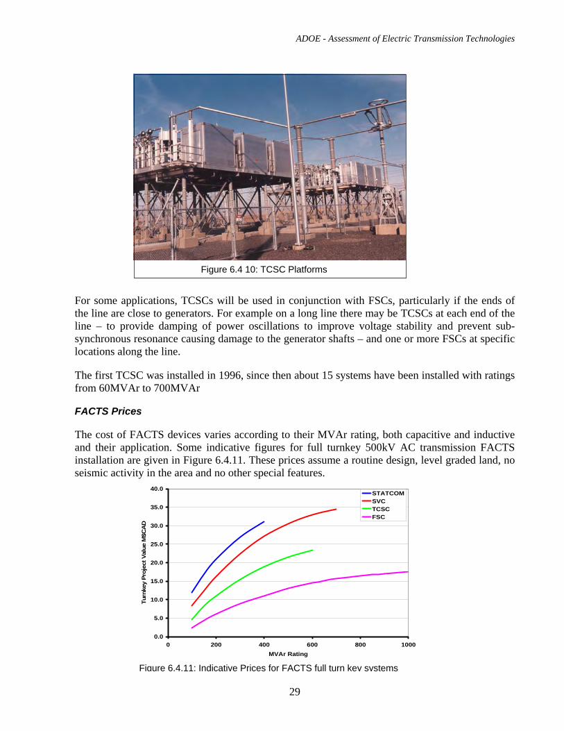
A typical TCSC platform is shown in Figure 6.4.10.
Figure 6.4.7: FSC basic i i
Figure 6.4.8: A typical FSC installation, showing all three phases of compensation built on insulated platforms
Figure 6.4.9: TCSC basic circuit
ADOE - Assessment of Electric Transmission Technologies
29
For some applications, TCSCs will be used in conjunction with FSCs, particularly if the ends of the line are close to generators. For example on a long line there may be TCSCs at each end of the line – to provide damping of power oscillations to improve voltage stability and prevent sub-synchronous resonance causing damage to the generator shafts – and one or more FSCs at specific locations along the line.
The first TCSC was installed in 1996, since then about 15 systems have been installed with ratings from 60MVAr to 700MVAr
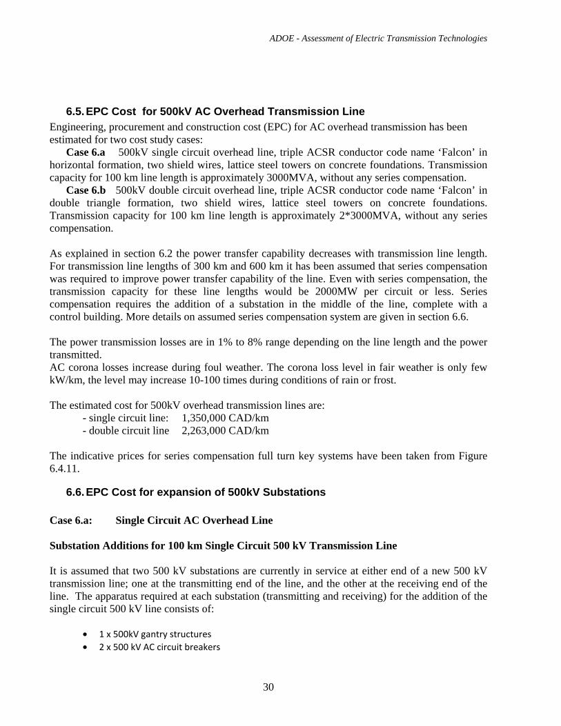
FACTS Prices
The cost of FACTS devices varies according to their MVAr rating, both capacitive and inductive and their application. Some indicative figures for full turnkey 500kV AC transmission FACTS installation are given in Figure 6.4.11. These prices assume a routine design, level graded land, no seismic activity in the area and no other special features.
Figure 6.4 10: TCSC Platforms
Figure 6.4.11: Indicative Prices for FACTS full turn key systems
0.0
5.0
10.0
15.0
20.0
25.0
30.0
35.0
40.0
0 200 400 600 800 1000MVAr Rating
Turn
key
Proj
ect V
alue
M$C
AD
STATCOMSVCTCSCFSC
ADOE - Assessment of Electric Transmission Technologies
30
6.5. EPC Cost for 500kV AC Overhead Transmission Line Engineering, procurement and construction cost (EPC) for AC overhead transmission has been estimated for two cost study cases:
Case 6.a 500kV single circuit overhead line, triple ACSR conductor code name ‘Falcon’ in horizontal formation, two shield wires, lattice steel towers on concrete foundations. Transmission capacity for 100 km line length is approximately 3000MVA, without any series compensation.
Case 6.b 500kV double circuit overhead line, triple ACSR conductor code name ‘Falcon’ in double triangle formation, two shield wires, lattice steel towers on concrete foundations. Transmission capacity for 100 km line length is approximately 2*3000MVA, without any series compensation.
As explained in section 6.2 the power transfer capability decreases with transmission line length. For transmission line lengths of 300 km and 600 km it has been assumed that series compensation was required to improve power transfer capability of the line. Even with series compensation, the transmission capacity for these line lengths would be 2000MW per circuit or less. Series compensation requires the addition of a substation in the middle of the line, complete with a control building. More details on assumed series compensation system are given in section 6.6. The power transmission losses are in 1% to 8% range depending on the line length and the power transmitted. AC corona losses increase during foul weather. The corona loss level in fair weather is only few kW/km, the level may increase 10-100 times during conditions of rain or frost. The estimated cost for 500kV overhead transmission lines are: - single circuit line: 1,350,000 CAD/km - double circuit line 2,263,000 CAD/km The indicative prices for series compensation full turn key systems have been taken from Figure 6.4.11.
6.6. EPC Cost for expansion of 500kV Substations Case 6.a: Single Circuit AC Overhead Line Substation Additions for 100 km Single Circuit 500 kV Transmission Line It is assumed that two 500 kV substations are currently in service at either end of a new 500 kV transmission line; one at the transmitting end of the line, and the other at the receiving end of the line. The apparatus required at each substation (transmitting and receiving) for the addition of the single circuit 500 kV line consists of:
• 1 x 500kV gantry structures • 2 x 500 kV AC circuit breakers
ADOE - Assessment of Electric Transmission Technologies
31
• 4 x 500 kV motor operated disconnect switches (breaker disconnects) • 1 x 500 kV motor operated disconnect switch (line disconnect) • 3 x 500 kV lightning arresters • 3 x 500 kV CVTs • 6 x 500 kV CTs
For the purposes of this study the following assumptions have been made with respect to the substations:
o Land costs were not considered for the substations o 500 kV AC substations exist on both the transmitting and receiving ends of the 500 kV AC
transmission line o Provision was made only for modifications to these two existing 500 kV substations, adding
the breakers, disconnects, bus work, CTs , CVTs and lightning arresters as required for the expansion
o For the 100 km line length, series compensation is not required. o The substations have switchyards large enough to accommodate the addition of the electrical
apparatus required for the addition of the transmission line o The substation control buildings have sufficient space to accommodate the addition of the
required protection and SCADA panels o The substation AC station service has sufficient capacity for the new apparatus and equipment o Escalation was not included o Allowance for funds used during construction (AFUDC) was not included o 10% contingency was included
The estimated costs for the substation additions and modifications for adding a single circuit 500 kV overhead transmission line are: - per substation: $33,658,000CAD - for 2 substations: $67,316,000CAD Substation Additions for 300 km Single Circuit 500 kV Transmission Line Substation additions required for a 300 km, 500 kV transmission line are similar to that shown above for the 100 km transmission line, except that one series compensation device is now required in the middle of the transmission line. The series compensation required can take the following forms:
• Fixed series compensator (FSC) • Thyristor controlled series compensator (TCSC)
In order to determine what type of series compensation is required for a particular application rigorous system studies are required. Since system studies are not part of the project scope for this project, an assumption was made that the TCSC technology will be used, and provisions were made for using this technology.
ADOE - Assessment of Electric Transmission Technologies
32
For the 300 km length line, it was assumed that a 600 MVAr TCSC was installed in the middle of the line. This required the addition of a substation at this location, complete with a control building. The estimated costs for the substation additions and modifications for adding a single circuit 500 kV overhead transmission line are: - per substation: $33,658,000CAD - for 2 substations: $67,316,000CAD The estimated cost for a 600 MVAr Thyristor Controlled Series Compensator for a single circuit 500 kV overhead transmission line are: - per installation: $23,500,000. CAD Substation Additions for 600 km Single Circuit 500 kV Transmission Line Substation additions required for a 600 km, 500 kV transmission line are similar to that shown above for the 300 km transmission line, except that the list of apparatus required at each substation should now include:
• 3 x 500 kV switching reactors complete with lightning arresters (3 single phase units) • 1 x 500 kV AC circuit breakers • 1 x 500 kV motor operated disconnect switches (breaker disconnects)
As seen above, provision was made for a 500 kV switching reactor at both ends of the transmission line in order to limit open circuit voltages to acceptable levels. It is assumed that three TCSC devices are now required at regular interval along the transmission line. It is not known if three TCSCs in series will operate in a stable manner. System studies are required, which are beyond the scope of this project. Regardless provisions were made for the addition of three TCSC units. The estimated costs for the substation additions and modifications for adding a single circuit 500 kV overhead transmission line are: - per substation: $45,718,000CAD - for 2 substations: $91,436,000CAD The estimated cost for three 600 MVAr Thyristor Controlled Series Compensators for a single circuit 500 kV overhead transmission line are: - per installation: $23,500,000 CAD - for 3 installations: $70,500,000 CAD Case 6.b: Double Circuit AC Overhead Line Substation Additions for Double Circuit 500 kV Transmission Line
ADOE - Assessment of Electric Transmission Technologies
33
Since the substation apparatus required for a second 500 kV transmission line is almost double that required for a single circuit transmission line, therefore the costs were almost doubled. The same assumptions were used for the double circuit transmission line as described above for the single circuit transmission line. Substation Additions’ Costs for 100 km and 300 km Double Circuit 500 kV Transmission Line
- per substation: $67,316,000CAD - for 2 substations: $134,632,000CAD Substation Additions’ Costs for 600 km Double Circuit 500 kV Transmission Line
- per substation: $91,436,000CAD - for 2 substations: $182,872,000CAD Series Compensation (100 km, 300 km and 600 km) Similar to the single circuit transmission line for the 100 km double circuit 500 kV transmission line, no series compensation is required. For the 300 km double circuit line, two 600 MVAr TSCS units were required, one for each transmission line circuit. For the 600 km double circuit line, six 600 MVAr TSCS units are required, three for each transmission line circuit. Similar to the single circuit compensation, it is not known if three TCSC in series will operate in a stable manner.
6.7. Right of Way Requirements A transmission line right-of-way defines a strip of land needed to locate, build, operate and maintain an overhead or underground electric transmission line or cable. It provides a safety margin between the high voltage lines and surrounding structures and vegetation. The right of way width should be sufficient to ensure there is safe clearance to structures and other objects within or outside of the right-of-way. Typically the following criteria have been used to decide the transmission line right-of-way width :
a. CAN/CSA-C22.3 N0. 1-06 and AEUC horizontal clearances and conductor swing under moderate wind pressure of 230Pa.
b. 60 Hz flashover clearances and conductor swing under high wind. c. Switching surge flashover clearance and conductor swing under five year return wind.
The criteria (a) and (c) are currently used in Alberta. Based on the criteria stated above the right-of-way width for single circuit AC 500kV transmission line is estimated to be in range of 58 m to 65 m. For double circuit AC 500kV line the right-of-way width is estimated to be in range 62 m to 67 m. An illustration of determining the right-of-way width for double circuit transmission line considered in cost study case 6.b is shown in Fig. 6.1.1(a). The design parameters pertinent to each line design will determine the right-of-way width. These parameters include: span between
ADOE - Assessment of Electric Transmission Technologies
34
structures, conductor sag, arrangement of insulator set “I” or “V”, specified electrical clearances, layout of phase conductors etc. Use of the area inside the overhead transmission line right-of –way is allowed but it is restricted. Transmission lines are designed so that safe electrical clearances are maintained during the line’s operation. The height of the energized conductors above ground accessible to vehicles and over the farmland is sufficient to allow large vehicles (i.e. trucks and standard agricultural machines) to safely pass under the conductors. The land under a transmission line can be used for agriculture purposes, however the growing of tall trees or constructing buildings under a transmission line is not allowed. Some activities such as flying kites or hot air balloons or operating tall machinery (cranes) in the area below and surrounding a transmission line can be dangerous. The right-of-way will be so arranged that ground access for maintenance and urgent repairs is available at all times.
6.8. Environmental Impact
The environmental effects of overhead transmission lines are minimized through line design process, and environmental protection measures implemented during construction and operation of the line. Environmental impact studies for new projects consider the effects of tree cutting, soil erosion, fish and wildlife impacts and other effects. It is always possible to restore the right-of –way area after the line construction so that the surrounding ground, waters and vegetation rest unaffected. Sensitive areas such as wilderness, scenic areas, First Nation sites and burial grounds, parks and historical sites should be given special consideration and be avoided if possible.
The electrical influences on the environment caused by high voltage power transmission lines include:
The effects of electric fields The effects of magnetic fields Radio interference Audible noise Ground currents and corrosion effects
Electric and Magnetic Fields
An electric field is produced by electrically charged particles. Electric field exists around electrically charged conductors regardless if electric current flows or not. If there is a voltage there is an electric field. A magnetic field is produced when electrically charged particles move. Magnetic field will exist if a current flows in a conductor. Its intensity is proportional to the magnitude of the current.
Transmission lines are designed so that potential effects of electric and magnetic fields are eliminated or minimized. Electric fields are the cause of electric charge that may appear on vehicles and large objects under a transmission line. CSA standard C22.3 No. 1-06 stipulates the minimum line to ground clearances for electric overhead lines so that this charge is practically below a person’s perception threshold. The variable AC magnetic fields induce voltages and currents in long objects such as fences and pipelines. These effects can be predicted by calculation so that efficient mitigation measures are easily implemented.

ADOE - Assessment of Electric Transmission Technologies
35
The health effects from exposure to power transmissions line frequency electric and magnetic fields have been studied since the 1980s. Most of the organizations involved agree that there is no conclusive scientific evidence on adverse health effects for people living in the vicinity of high voltage lines. Nevertheless this remains a controversial issue and there is no general consensus between experts and within the general population. Therefore we present hereafter several quotations from documents issued by organizations who are directing and coordinating authorities for health issues for electromagnetic fields.
World Health Organization (WHO)
Excerpts from the document: Electromagnetic fields (EMF) – Summary of health effects
http://www.who.int/peh-emf/about/WhatisEMF/en/index1.html
“Based on a recent in-depth review of the scientific literature, the WHO concluded that current evidence does not confirm the existence of any health consequences from exposure to low level electromagnetic fields. However, some gaps in knowledge about biological effects exist and need further research”.
“A number of epidemiological studies suggest small increases in risk of childhood leukemia with exposure to low frequency magnetic fields in the home. However, scientists have not generally concluded that these results indicate a cause-effect relation between exposure to the fields and disease (as opposed to artifacts in the study or effects unrelated to field exposure). In part, this conclusion has been reached because animal and laboratory studies fail to demonstrate any reproducible effects that are consistent with the hypothesis that fields cause or promote cancer. Large-scale studies are currently underway in several countries and may help resolve these issues”.
International Agency for Research on Cancer
Excerpts from the document: World Cancer Report 2008 – Chapter 12.2
http://www.iarc.fr/en/publications/pdfs-online/wcr/index.php
“Extremely low frequency electromagnetic fields generated by electrical power transmission have been associated with an increased risk of childhood leukaemia, but the findings are not conclusive. Even if this association is real, the number of excess cases is likely to be very small.” “To date there is no convincing biological or biophysical support for a possible association between exposure to ELF fields and the risk of leukaemia or any other cancer.”
International Exposure Guidelines
International Commission on Non-Ionizing Radiation Protection (ICNIRP) has issued ‘Guidelines for Limiting Exposure to Time-Varying Electric, Magnetic, and Electromagnetic Fields (up to 300 GHz)’. The values in Table 6.8(a) are reference levels for low frequency electromagnetic fields that should not be exceeded.
ADOE - Assessment of Electric Transmission Technologies
36
Exposure Frequency Electric Field [kV/m] Magnetic Field [μ Τ] Occupational Up to 1Hz - 2*105 Occupational 60 Hz 8.33 416.66 General Public Up to 1Hz - 4*104 General Public 60 Hz 4.166 83.3 Table 6.8 (a). Reference levels for exposure to time-varying electric and magnetic fields (unperturbed rms values) IEEE Std C95.6-2002, ‘Standard for Safety Levels with Respect to Human Exposure to Electromagnetic Fields, 0-3 kHz’ recommends slightly higher permissible levels of exposure. Because of the known potential for interference with pacemakers by 60-Hz electromagnetic fields, field limits for pacemaker wearers have been established by the American Conference of Governmental Industrial Hygienists ACGIH. They recommend that wearers of pacemakers limit their exposure to electric fields of 1 kV/m or less and to magnetic fields to 1 G (100micro Tesla) or less. The electric field in a right-of-way under a transmission line normally exceeds 1kV/m, therefore pacemakers wearers should be discouraged from using right-of-way unless their pacemaker is designed against potential field interference.
The electric and magnetic fields at the edge of the right-of-way of the overhead transmission lines are normally less than the reference levels established in the ICNRIP guidelines. Fig. 6.8(a) and Fig. 6.8(b) show the result of the calculation of electric field and magnetic field across of lateral section of 500kV double circuit overhead transmission line that has been considered for the cost estimate described in the section 6.5. The calculated field levels are reported at a height of one meter above ground.
ADOE - Assessment of Electric Transmission Technologies
37
500 kV AC TL Electric Field Lateral Profile
0
1
2
3
4
5
6
7
8
9
-50 -45 -40 -35 -30 -25 -20 -15 -10 -5 0 5 10 15 20 25 30 35 40 45 50
Distance from Centerline [m]
Fiel
d at
1m
abo
ve g
roun
d [k
V/m
]
R.O
.W e
dge
Fig. 6.8(a) Electric field lateral profile below 500 kV double circuit overhead transmission line
500 kV AC TL Magnetic Field Lateral Profile
0
5
10
15
20
25
30
35
-50 -45 -40 -35 -30 -25 -20 -15 -10 -5 0 5 10 15 20 25 30 35 40 45 50
Distance from Centreline [m]
Mag
netic
Flu
x D
ensit
y at
1m
abo
ve g
roun
d [ μ
T]
R.O
.W. e
dge
Fig. 6.8(b) Magnetic field lateral profile below 500 kV double circuit overhead transmission line, the above diagram is calculated for 2 x 2000MW power flow.
ADOE - Assessment of Electric Transmission Technologies
38
Radio Noise Radio and television frequency interference from overhead transmission lines is caused by two physical processes: partial electrical discharges (corona) and complete electrical discharges across small gaps called micro-sparks. Corona may occur on conductors and insulator hardware and is prevented by proper design of conductors, hardware and line spacing. Micro-sparks occur at polluted insulators and defective hardware and are prevented by correct installation and adequate maintenance. Radio and television noise generated by AC lines is function of weather conditions. Canadian standard CSA C108.3.1-M84, ‘Limits and Measurement Methods of Electromagnetic Noise from AC Power Systems 0.15 - 30 MHz’, specifies that the fair weather noise field strength, at 0.5 MHz and 15m away from the outmost conductor of the transmission line shall not exceed the limits specified in table 6.8(b). The standard also provides the method to recalculate permissible noise levels for frequencies other than 0.5 MHz. Nominal Phase to Phase Voltage, kV Electromagnetic noise field strength, dB above
1 microV/m 200 - 300 53 300 - 400 56 400- 600 60 600- 800 63
Table 6.8(b) Limits of Electromagnetic Noise
ADOE - Assessment of Electric Transmission Technologies
39
Audible Noise Audible noise is produced by corona on energized parts of a transmission line such as conductors and insulator fittings. Under dry weather conditions, the line normally operates below the corona inception level and few points of corona emission are present. In foul weather, water drops on conductors producing corona discharges, which create audible noise. Audible noise from transmission lines can be classified as quiet sounds and is measured in A-weighted decibels (dBA). Commonly encountered audible noise levels are listed in the table below. Truck at 15m 80 dBANormal conversation indoors 60 dBAModerate rainfall 50 dBA Refrigerator 40 dBA Bedroom at night 25 dBA Threshold of hearing 0 dBA Table 6.8(c). Sound intensities of common acoustics sources The audible noise from transmission lines in Alberta shall not exceed the permissible noise limits as set down in Alberta Utilities Commission (AUC), Rule No. 012 – Noise Control. The permissible noise levels for rural sites with 1 – 8 dwellings are 40 dBA during the nighttime and 50 dBA during the daytime. AC corona increases during the rain but at the same time the background noise increases as well, therefore it has been accepted that these permissible noise levels relate to fair weather conditions. Ground Currents and Corrosion Effects Under normal operating conditions, the currents that flow through the AC overhead transmission line towers to the ground are very small and they will not affect the infrastructure installations nearby. When overhead transmission lines are being built near metallic pipelines, the transmission lines and the pipelines can operate safely in the common corridor. Any effects on pipelines are successfully eliminated or reduced to acceptable levels by the standard mitigative techniques that address the following:
- Magnetic Field Coupling – AC magnetic field from transmission line can induce voltages and currents in underground and above-ground pipeline. Mitigative measures can be required to protect workers, pipeline equipment and cathodic protection system.
- Conductive Coupling – in case of ground fault on transmission line the ground electrical potential rises at location where fault current is injected into ground. Voltage differences develop across the pipe insulation. Damage to pipeline insulating coating can cause corrosion to pipeline.
- Electric Field Coupling – an electric charge can build up on aboveground pipelines or during the pipeline installation.
ADOE - Assessment of Electric Transmission Technologies
40
6.9. Operation and Maintenance During normal operation overhead transmission lines require regular periodic inspections and vegetation management. Normally, very little intervention is required. Inspections can be done using a helicopter or plane. When a closer inspection is required ground vehicles are used. In some countries, the monitoring system with cameras and transducers to record the movement of conductors, climatic loadings and sag and temperature of conductors is employed. Fault locator systems with GPS are also available. Any materials found in substandard condition are replaced during the planned power outage. Where live line maintenance techniques are used no power outage is required. Access roads are maintained in good condition so that response crews can reach the line without delay. The response crews work around the clock and in all weathers. Transmission facilities owners have special emergency structures and spare materials ready to be used for emergency service restoration so that the power outage time is kept to a minimum.
6.10. Examples of Application High voltage AC transmission lines in a voltage range from 110 kV to 765 kV are commonly used around the world. Voltage levels of 735 kV or 765 kV are in use in Canada, Brazil, India, Russia, South Africa, South Korea, USA and Venezuela. Ultra high voltage AC transmission lines of 1000 kV and above have been built in Japan and Russia. The 432 km long AC transmission line connecting Ekibastus and Kokshetau in Kazakhstan operates at 1150 kV and holds the record for highest operating transmission voltage in the world. The 1487 km 500kV AC transmission line interconnects three regional transmission systems in Vietnam. The length of the longest segment is 496 km. Four AC 500 kV transmission lines have been built in Alberta:
• Line 1201L from Langdon substation near Calgary to British Columbia. The line operates at 500 kV.
• Line 1202L from Keephills to Ellerslie substation. Presently the line operates at 240 kV. • Line 1203L from Genesee to Keephills substation. This line operates at 500 kV. • Line 1209L from Genesee to Ellerslie substation. This line operates at 500 kV.
7. AC Underground Transmission Cable
7.1. Description of the technology and available suppliers for materials (E)
7.1.1 Introduction
ADOE - Assessment of Electric Transmission Technologies
41
According to a recent worldwide survey carried out by CIGRE WG B1.10, the predominant underground cable types are XLPE and SCFF. At voltages above 220 kV, SCFF accounted for about 40% of cables installed between 2000 and 2005 but there is a trend towards the use of XLPE and this is expected to continue up to the highest voltage levels. Descriptions of the following four extra high voltage (EHV) AC underground cable systems will be presented in the following subsections: • High-pressure pipe-type cable systems (HPFF) • Self-contained fluid - filled cable systems (SCFF) • Extruded dielectric cable systems (XLPE) • Gas-insulated Line Systems (GIL) HPFF and GIL cable systems have been included in addition to the two most prominent technologies because of the importance of the former in North America and because since 2005 GIL systems are beginning to be used in underground applications. Mass impregnated (MI) are not used for alternating current transmission at EHV voltage levels and are not addressed.
7.1.2 High-pressure fluid-filled (HPFF) pipe-type cable systems HPFF cables are insulated with Kraft paper or laminated paper/polypropylene/ paper (PPP) tapes impregnated with high-viscosity synthetic oil. D-section skid wires, which are typically stainless steel, are wound helically around the cable to reduce friction between the cables and the pipe wall and protect the cable shielding and insulation during installation. Three phases are drawn into a common steel pipe which is coated with an insulating material and provided with cathodic protection. The space between cables and pipe is filled with a low-viscosity synthetic fluid (alkylbenzene or polybutene) which is pressurised to a minimum of 200 psi to improve electric strength of the cable insulation. The use of PPP insulation in place of Kraft paper allows a reduced insulation wall and cable pipe diameter and an improved power transmission capacity. Figure 7.1(a), compares the sizes of Kraft paper and PPP insulated HPFF systems with equal power transmission ratings. The highest in-service operating voltage for HPFF cable is 345 kV with 525 kV (2) and 765 kV systems having successfully passed long term field testing at the EPRI Test Center at Waltz Mill in Pennsylvania in the 1980’s. However, those cable constructions are no longer produced, and new tests would be required for 525-kV cable to be installed today. Suppliers of HPFF Systems include Okonite (New Jersey), Prysmian (St. Jean, Quebec), and Viscas (Japan).
2 A 500-kV ac system would be served by 525-kV class cables; we will use the 525-kV cable designation throughout this document
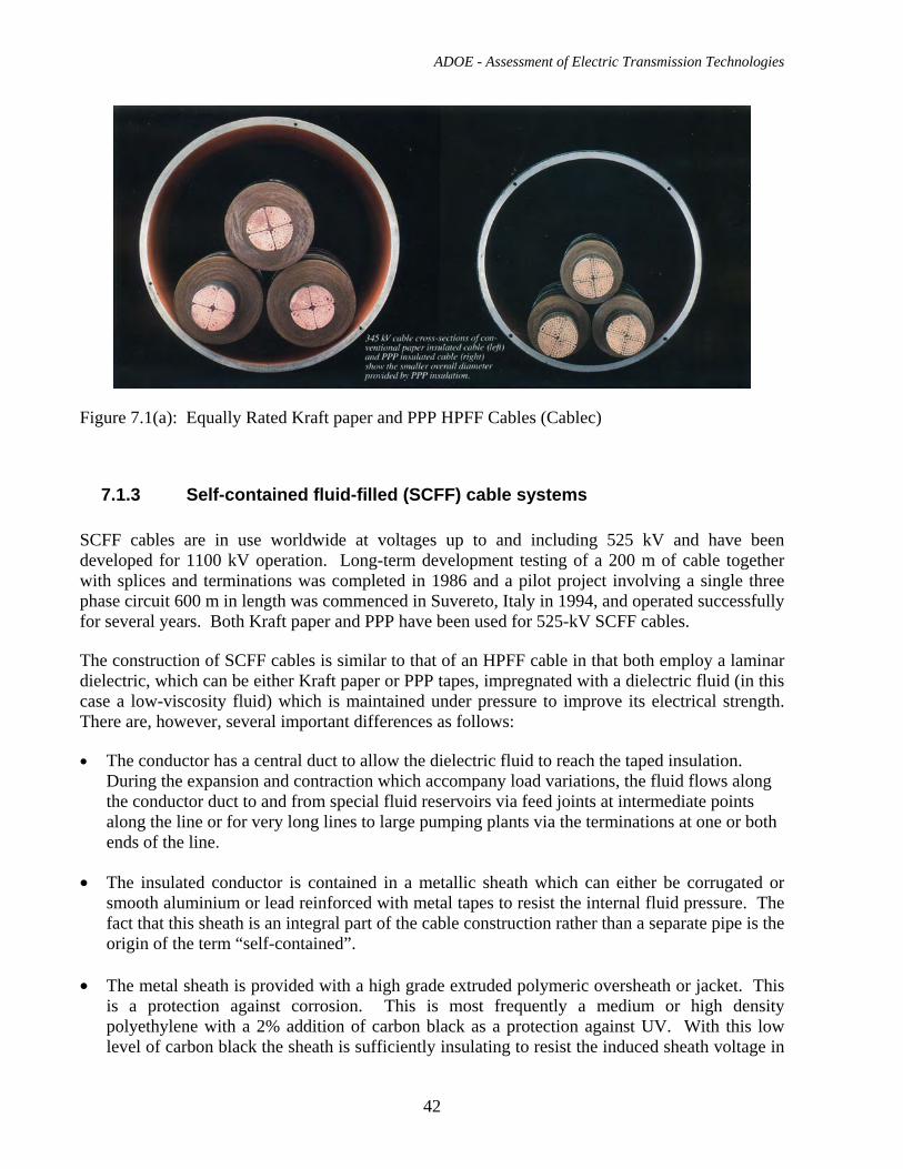
ADOE - Assessment of Electric Transmission Technologies
42
Figure 7.1(a): Equally Rated Kraft paper and PPP HPFF Cables (Cablec)
7.1.3 Self-contained fluid-filled (SCFF) cable systems SCFF cables are in use worldwide at voltages up to and including 525 kV and have been developed for 1100 kV operation. Long-term development testing of a 200 m of cable together with splices and terminations was completed in 1986 and a pilot project involving a single three phase circuit 600 m in length was commenced in Suvereto, Italy in 1994, and operated successfully for several years. Both Kraft paper and PPP have been used for 525-kV SCFF cables. The construction of SCFF cables is similar to that of an HPFF cable in that both employ a laminar dielectric, which can be either Kraft paper or PPP tapes, impregnated with a dielectric fluid (in this case a low-viscosity fluid) which is maintained under pressure to improve its electrical strength. There are, however, several important differences as follows: • The conductor has a central duct to allow the dielectric fluid to reach the taped insulation.
During the expansion and contraction which accompany load variations, the fluid flows along the conductor duct to and from special fluid reservoirs via feed joints at intermediate points along the line or for very long lines to large pumping plants via the terminations at one or both ends of the line.
• The insulated conductor is contained in a metallic sheath which can either be corrugated or
smooth aluminium or lead reinforced with metal tapes to resist the internal fluid pressure. The fact that this sheath is an integral part of the cable construction rather than a separate pipe is the origin of the term “self-contained”.
• The metal sheath is provided with a high grade extruded polymeric oversheath or jacket. This
is a protection against corrosion. This is most frequently a medium or high density polyethylene with a 2% addition of carbon black as a protection against UV. With this low level of carbon black the sheath is sufficiently insulating to resist the induced sheath voltage in
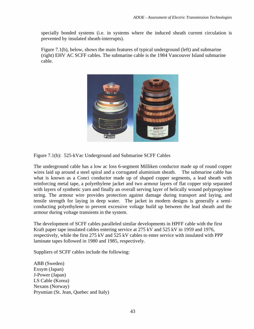
ADOE - Assessment of Electric Transmission Technologies
43
specially bonded systems (i.e. in systems where the induced sheath current circulation is prevented by insulated sheath-interrupts).
Figure 7.1(b), below, shows the main features of typical underground (left) and submarine (right) EHV AC SCFF cables. The submarine cable is the 1984 Vancouver Island submarine cable.
Figure 7.1(b): 525-kVac Underground and Submarine SCFF Cables The underground cable has a low ac loss 6-segment Milliken conductor made up of round copper wires laid up around a steel spiral and a corrugated aluminium sheath. The submarine cable has what is known as a Conci conductor made up of shaped copper segments, a lead sheath with reinforcing metal tape, a polyethylene jacket and two armour layers of flat copper strip separated with layers of synthetic yarn and finally an overall serving layer of helically wound polypropylene string. The armour wire provides protection against damage during transport and laying, and tensile strength for laying in deep water. The jacket in modern designs is generally a semi-conducting polyethylene to prevent excessive voltage build up between the lead sheath and the armour during voltage transients in the system. The development of SCFF cables paralleled similar developments in HPFF cable with the first Kraft paper tape insulated cables entering service at 275 kV and 525 kV in 1959 and 1976, respectively, while the first 275 kV and 525 kV cables to enter service with insulated with PPP laminate tapes followed in 1980 and 1985, respectively. Suppliers of SCFF cables include the following: ABB (Sweden) Exsym (Japan) J-Power (Japan) LS Cable (Korea) Nexans (Norway) Prysmian (St. Jean, Quebec and Italy)
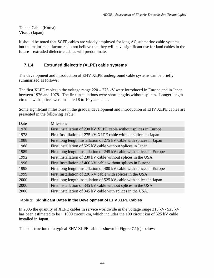
ADOE - Assessment of Electric Transmission Technologies
44
Taihan Cable (Korea) Viscas (Japan) It should be noted that SCFF cables are widely employed for long AC submarine cable systems, but the major manufacturers do not believe that they will have significant use for land cables in the future – extruded dielectric cables will predominate.
7.1.4 Extruded dielectric (XLPE) cable systems The development and introduction of EHV XLPE underground cable systems can be briefly summarized as follows: The first XLPE cables in the voltage range 220 – 275 kV were introduced in Europe and in Japan between 1976 and 1978. The first installations were short lengths without splices. Longer length circuits with splices were installed 8 to 10 years later. Some significant milestones in the gradual development and introduction of EHV XLPE cables are presented in the following Table: Date Milestone 1978 First installation of 230 kV XLPE cable without splices in Europe 1978 First Installation of 275 kV XLPE cable without splices in Japan 1988 First long length installation of 275 kV cable with splices in Japan 1988 First installation of 525 kV cable without splices in Japan 1989 First long length installation of 245 kV cable with splices in Europe 1992 First installation of 230 kV cable without splices in the USA 1996 First Installation of 400 kV cable without splices in Europe 1998 First long length installation of 400 kV cable with splices in Europe 1999 First Installation of 230 kV cable with splices in the USA 2000 First long length installation of 525 kV cable with splices in Japan 2000 First installation of 345 kV cable without splices in the USA 2006 First installation of 345 kV cable with splices in the USA. Table 1: Significant Dates in the Development of EHV XLPE Cables In 2005 the quantity of XLPE cables in service worldwide in the voltage range 315 kV- 525 kV has been estimated to be ~ 1000 circuit km, which includes the 100 circuit km of 525 kV cable installed in Japan. The construction of a typical EHV XLPE cable is shown in Figure 7.1(c), below:
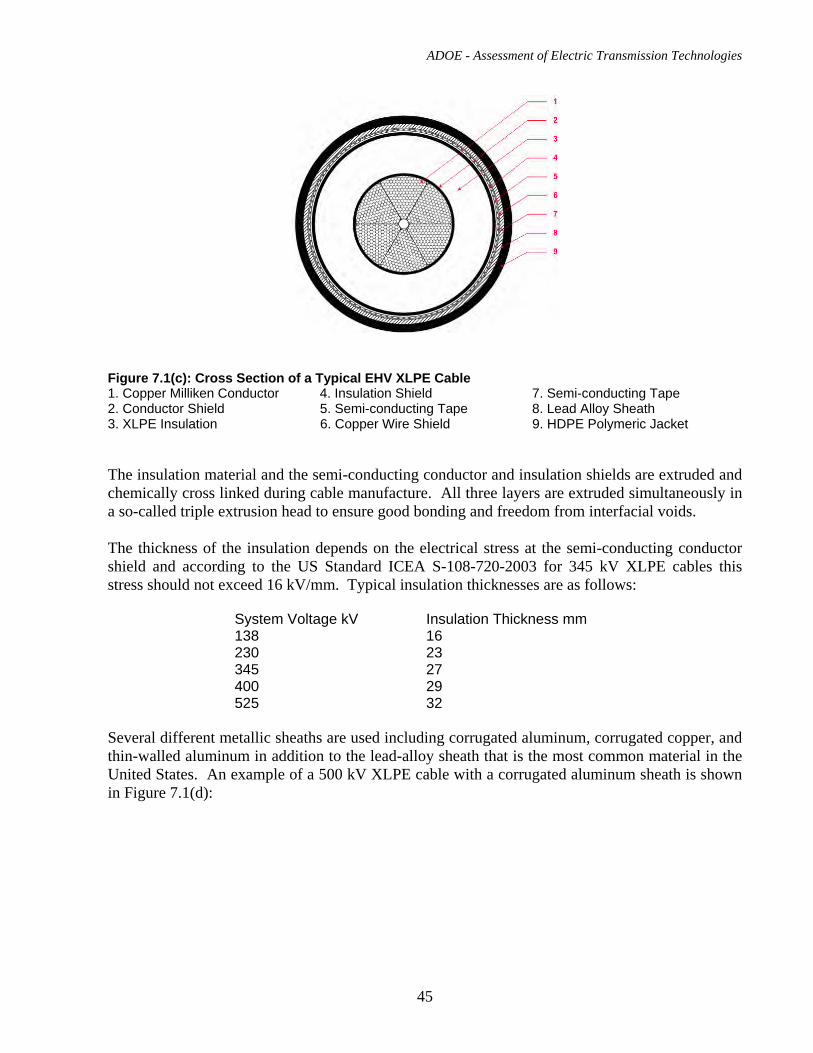
ADOE - Assessment of Electric Transmission Technologies
45
Figure 7.1(c): Cross Section of a Typical EHV XLPE Cable 1. Copper Milliken Conductor 4. Insulation Shield 7. Semi-conducting Tape 2. Conductor Shield 5. Semi-conducting Tape 8. Lead Alloy Sheath 3. XLPE Insulation 6. Copper Wire Shield 9. HDPE Polymeric Jacket The insulation material and the semi-conducting conductor and insulation shields are extruded and chemically cross linked during cable manufacture. All three layers are extruded simultaneously in a so-called triple extrusion head to ensure good bonding and freedom from interfacial voids. The thickness of the insulation depends on the electrical stress at the semi-conducting conductor shield and according to the US Standard ICEA S-108-720-2003 for 345 kV XLPE cables this stress should not exceed 16 kV/mm. Typical insulation thicknesses are as follows:
System Voltage kV Insulation Thickness mm 138 16 230 23 345 27 400 29 525 32
Several different metallic sheaths are used including corrugated aluminum, corrugated copper, and thin-walled aluminum in addition to the lead-alloy sheath that is the most common material in the United States. An example of a 500 kV XLPE cable with a corrugated aluminum sheath is shown in Figure 7.1(d):
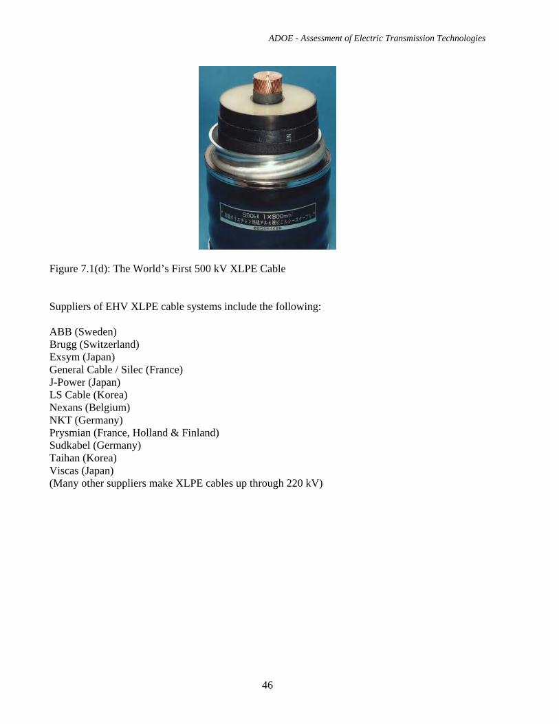
ADOE - Assessment of Electric Transmission Technologies
46
Figure 7.1(d): The World’s First 500 kV XLPE Cable Suppliers of EHV XLPE cable systems include the following: ABB (Sweden) Brugg (Switzerland) Exsym (Japan) General Cable / Silec (France) J-Power (Japan) LS Cable (Korea) Nexans (Belgium) NKT (Germany) Prysmian (France, Holland & Finland) Sudkabel (Germany) Taihan (Korea) Viscas (Japan) (Many other suppliers make XLPE cables up through 220 kV)
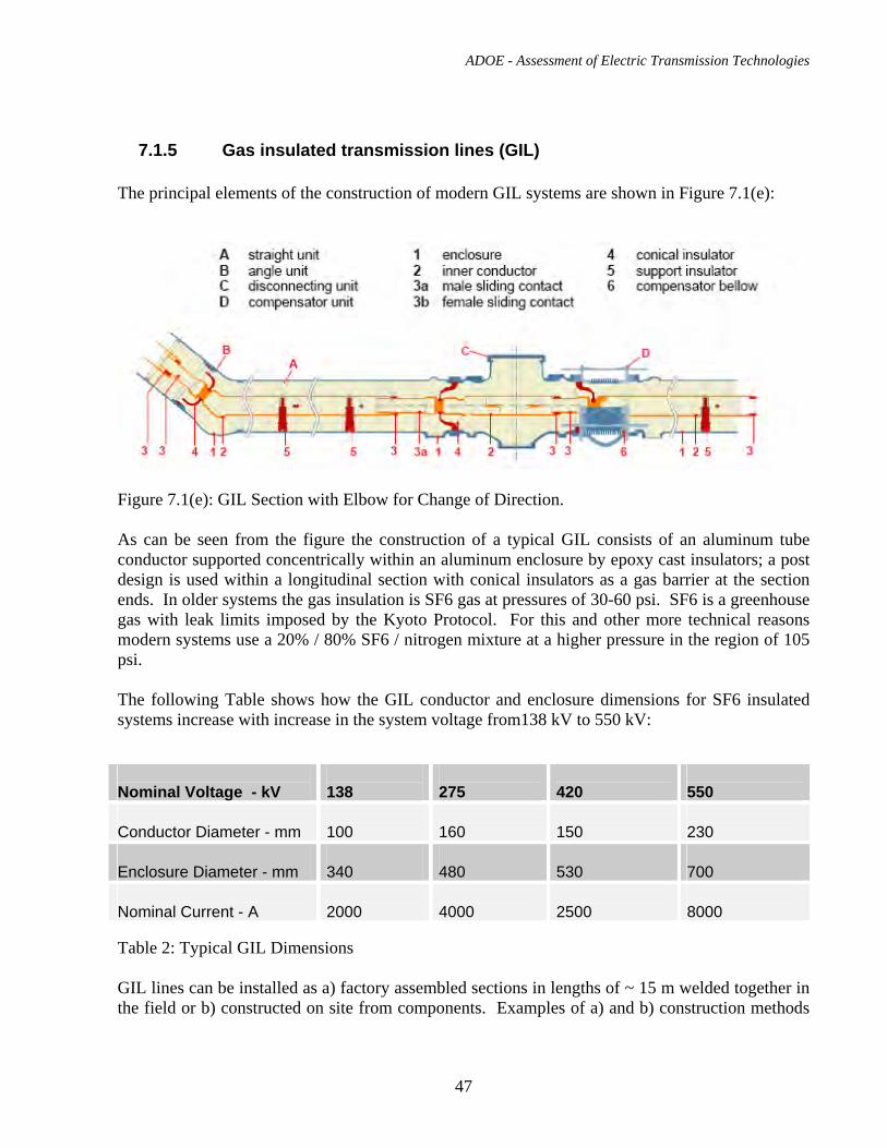
ADOE - Assessment of Electric Transmission Technologies
47
7.1.5 Gas insulated transmission lines (GIL) The principal elements of the construction of modern GIL systems are shown in Figure 7.1(e):
Figure 7.1(e): GIL Section with Elbow for Change of Direction. As can be seen from the figure the construction of a typical GIL consists of an aluminum tube conductor supported concentrically within an aluminum enclosure by epoxy cast insulators; a post design is used within a longitudinal section with conical insulators as a gas barrier at the section ends. In older systems the gas insulation is SF6 gas at pressures of 30-60 psi. SF6 is a greenhouse gas with leak limits imposed by the Kyoto Protocol. For this and other more technical reasons modern systems use a 20% / 80% SF6 / nitrogen mixture at a higher pressure in the region of 105 psi. The following Table shows how the GIL conductor and enclosure dimensions for SF6 insulated systems increase with increase in the system voltage from138 kV to 550 kV: Nominal Voltage - kV
138
275
420
550
Conductor Diameter - mm
100
160
150
230
Enclosure Diameter - mm
340
480
530
700
Nominal Current - A
2000
4000
2500
8000
Table 2: Typical GIL Dimensions GIL lines can be installed as a) factory assembled sections in lengths of ~ 15 m welded together in the field or b) constructed on site from components. Examples of a) and b) construction methods
ADOE - Assessment of Electric Transmission Technologies
48
include a 420 kV line in the UK which was commissioned in 2004 and a 550 kV line which has been in service in Thailand since 2002, respectively. Suppliers of GIL systems include: Areva (France) AZZ / CGIT Medway MA (USA) J-Power (Japan) Mitsubishi Electric Co. (Japan) Siemens (Germany) Viscas (Japan)
7.2. Typical Applications and Transmission Capacity EHV underground cable systems generally form only a small percentage of the transmission network. A 2003 European survey involving seventeen countries found that the average use of underground cable as a percentage of the total transmission network was 1.9 % for voltages in the range of 220 – 300 kV and dropped to only 0.5 % for higher voltages (380 – 400 kV). While these percentages have certainly increased since 2003 they still remain at a low level since they are only used in situations where the use of overhead lines is not practicable, such as : • Lines passing through densely populated areas (EPCOR – ‘Downtown Edmonton Supply and
Substation Project’, downtown Tokyo (Japan), London (UK), Berlin etc. • Overhead lines crossing the line of the new runway (Madrid’s Barahas Airport) • River, channel and estuary crossings (Ma Wan and Kap Shui Mun Cables Channel Crossing in
Hong Kong ) Typical EHV underground cable systems in a worldwide context and at the upper end of the voltage range, i.e. 400 – 500 kV, utilize either SCFF or XLPE cables in circuit length up to and including 10 km. Longer lengths are feasible, and a 2007 review identified some 50 HV and EHV circuits longer than 10 km that were in service throughout the world with the longest of these being a 500-kV, 40 km long XLPE cable circuit which was installed in Japan in the year 2000. Typical power transmission capacities at 400 – 500 kV are in the 900 – 1200 MVA range for both SCFF and XLPE cable types and depend mainly on the type of installation and the thermal properties of the environment. Matching the transmission capacities of associated overhead lines can generally only be achieved using a double circuit of underground cable per single overhead line circuit. Several different installation types exist, with duct and manhole circuits being favored in North America (for XLPE cables) while direct buried installation using special thermal backfills is the norm in Europe. In Japan all EHV cable circuits are installed in custom-built cable tunnels. Cable tunnels are now also being used in Europe in major cities, notably Berlin and London, because of utilities congestion under the streets and traffic problems due to open trenches during construction.
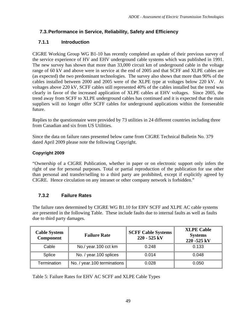
ADOE - Assessment of Electric Transmission Technologies
49
7.3. Performance in Service, Reliability, Safety and Efficiency
7.1.1 Introduction CIGRE Working Group WG B1-10 has recently completed an update of their previous survey of the service experience of HV and EHV underground cable systems which was published in 1991. The new survey has shown that more than 33,000 circuit km of underground cable in the voltage range of 60 kV and above were in service at the end of 2005 and that SCFF and XLPE cables are (as expected) the two predominant technologies. The survey also shows that more than 90% of the cables installed between 2000 and 2005 were of the XLPE type at voltages below 220 kV. At voltages above 220 kV, SCFF cables still represented 40% of the cables installed but the trend was clearly in favor of the increased application of XLPE cables at EHV voltages. Since 2005, the trend away from SCFF to XLPE underground cables has continued and it is expected that the main suppliers will no longer offer SCFF cables for underground applications within the foreseeable future. Replies to the questionnaire were provided by 73 utilities in 24 different countries including three from Canadian and six from US Utilities. Since the data on failure rates presented below came from CIGRE Technical Bulletin No. 379 dated April 2009 please note the following Copyright. Copyright 2009 “Ownership of a CIGRE Publication, whether in paper or on electronic support only infers the right of use for personal purposes. Total or partial reproduction of the publication for use other than personal and transfer/selling to a third party are prohibited, except if explicitly agreed by CIGRE. Hence circulation on any intranet or other company network is forbidden.”
7.3.2 Failure Rates The failure rates determined by CIGRE WG B1.10 for EHV SCFF and XLPE AC cable systems are presented in the following Table. These include faults due to internal faults as well as faults due to third party damages.
Cable System Component Failure Rate SCFF Cable Systems
220 - 525 kV
XLPE Cable Systems
220 -525 kV Cable No./ year.100 cct km 0.248 0.133
Splice No. / year.100 splices 0.014 0.048
Termination No. / year.100 terminations 0.028 0.050
Table 5: Failure Rates for EHV AC SCFF and XLPE Cable Types
ADOE - Assessment of Electric Transmission Technologies
50
It should also be noted that the failure rates for SCFF cable include fluid leakages and also that the average age of the SCFF systems is significantly greater than that of the XLPE cable systems. For a more complete discussion of the failure data reported in Table 5, reference should be made to CIGRE TB 379. Based on the cable failure data reported in Table 5 and considering a circuit length of 40 km the number of cable failures to be expected during the nominal 40 year life would be approximately four for SCFF cables or one failure every 10 years while for XLPE cables the expected failure rate would be one failure every 20 years. Expected failure rates for (six) terminations over 40 years are negligible for both SCFF and XLPE cable systems. For cable splices, on the other hand, expected failures (assuming splices every 500 m) during the nominal life would be one and two failures, respectively, for SCFF and XLPE cable systems. The conclusion of the statistical analysis is clearly that both EHV SCFF and XLPE cable systems can be considered to be highly reliable. According to CIGRE WG B1.10 most failures that do occur are repaired within two months with no difference in average repair times for SCFF and XLPE cable systems. The average outage time due to cable failures is stated to be 60 days. Due to low winter temperatures in Alberta the cable replacement time during winter can be significantly longer than reported by CIGRE. Preparations should be made so that specialized work can be performed in adverse weather conditions. It has to be taken into account that the lowest acceptable temperature for cable installation depends on the material used for the cable outer sheath. The CIGRE document does not provide failure rates for HPFF cables but from other sources, the failure rate for this cable type is not expected to differ significantly from the data quoted for SCFF and XLPE cable types. GIL lines were not included in the survey and no data are available for this report. Most of the installations are above ground or in tunnels and there were no buried GIL installation in 2005. Transmission cables are considered safe – the cable sheath (and the pipe of a pipe-type cable) is essentially at ground potential, and high-speed relaying interrupts fault current quickly. The major concern for public safety has been the lifting of manhole covers if a fault occurs in the manhole of a SCFF or XLPE-insulated cables.
ADOE - Assessment of Electric Transmission Technologies
51
7.4. Use of FACTS Devices to Enhance the Performance of AC System
Please see section 6.4 for a general description of FACTS solutions.
The main electrical difference between an overhead line and an underground cable is that, due to its high capacitance, a cable produces 30 to 40 times more reactive power per km than an overhead line. This can create more severe voltage and reactive power issues at much shorter transmission lengths than would be experienced by an overhead line.
Consequently, if a cable has a transmission distance of more than about 10km to 30km then some form of reactive power compensation (FACTS device) will most probably be required at the receiving end and maybe at an intermediate point along the cable.
It is also well established that once a cable transmission scheme has a length more than about 50km, irrespective of whether the cable is installed underground or under water, the overall investment and operational costs will normally be less if an HVDC solution is used. If an HVDC system is installed then the significant controllability benefits of HVDC described in section 9.4 will also be obtained.
The FACTS devices normally used with an AC cable scheme would be shunt connected: either an SVC or a STATCOM.
7.5. EPC Cost for 500kV AC Underground Cable Engineering, procurement and construction (EPC) cost has been estimated for 500kV double circuit underground XLPE cable transmission line with the trench cross section as shown in Fig. 7.7(a). It has been assumed that the required power transmission capacity of the line is 1200 MW. The lengths of the line considered were 50 km and 100 km. This cost study case has been designated as Case 7. When calculating current rating of an XLPE cable, among other factors, the following shall be considered:
Normal maximum operating temperature of XLPE cable is 90oC. Operating the cable at higher temperatures can damage the cable insulation.
The maximum summer ambient soil temperature in Alberta is 20 oC Generation of heat due to electric current in cable conductor – the size and material of
cable conductor Generation of heat in cable dielectric and cable shield Resistance to heat flow from cable to the ground surface should be minimal, therefore
thermal resistance of: cable insulation, cable jacket, (conduit, the duct bank –if applicable) and the surrounding earth should be low
The path of heat flow should be short, therefore the depth of cable burial have to be minimized
Wider spacing between cables will reduce mutual heating Burying the cable deeper in the ground to avoid obstacles will reduce the cable current
rating
ADOE - Assessment of Electric Transmission Technologies
52
Our calculated rating for 2500-mm2 500-kV XLPE cables buried in a flat configuration gives more than 1800 amperes (1560 MVA) using conservative assumptions for installation conditions. We have calculated reactive power of 20 MVAr/km Comments on the potential long AC cable lines assumed for the cost analysis are: 50-km Lines: Using the 1560 MVA rating and 20 MVAr/km reactive power requirement, a pair of 50-km single circuits could each carry 1200 MW, assuming they each have 500 MVAr reactive power compensation from shunt reactors at substations at each end (i.e. 1000 MVAr at each end; 2000 MVAr total). Such a long AC cable line has not been built yet, but it is technically feasible. 100-km Lines: Using the 1560 MVA rating and 20 MVAr/km reactive power requirement, a pair of 100-km single circuits could each carry 1200 MW, assuming they each have 1000 MVAr in reactors at substations at each end (i.e. 2000 MVAr at each end; 4000 MVAr total), without requiring mid-point compensation. Note that there could still be overvoltage and other system problems, but the required rating could be met. Although we used conservative values for installation parameters, it is still possible that some installation conditions (horizontal directional drill, installation through areas with poor soil thermal properties) could reduce the cable ratings below our calculated values. If one circuit were out of service, the remaining circuit could carry about 1350 MW for the two months that it might take to make a repair. The cost for such a long AC underground transmission line would be extremely high. As noted above, there could be overvoltage or other system problems with this arrangement. And, note that such a long AC system has never been attempted. If such a long underground cable were to be considered, a HVDC system should be evaluated. Costs for 50-km Underground Cable Line Recent budgetary unit costs for the supply ex-works (from factory ) Europe of a 500 kVac XLPE cable with a 2500 mm2 copper Milliken conductor are as follows: Cable cost: 590,000 Euro / km single cable 955,800 CAD / km single cable Splice cost: 40,000 Euro / pc 64,800 CAD / pc Termination Cost: 200,000 Euro / pc 324,000 CAD / pc Exchange rate as of July 4, 2009: Euro 1.0 = CAD 1.62 Construction cost including engineering, management, civil and cable installation works is estimated as follows: Double circuit cable line – trench cross section as in Fig 7.7(a) 2,785,840 CAD/km For the purpose of the cost estimate it has been assumed that the route length of underground cable line is 50 km and that shunt reactors were required at the transmitting substation and at receiving substation.. The line should be able to transmit power in both directions. More details are given in section 7.6. In view of the likely termination of the manufacture of SCFF cables for underground applications, only XLPE cables have been considered here (cf. Section 7.3.1).
ADOE - Assessment of Electric Transmission Technologies
53
Losses have been estimated at 75 W/m per circuit with one cable per phase and with cross-bonded sheaths.
7.6. EPC Cost for expansion of 500kV Substations The high voltage substation apparatus required for an underground 500 kV AC cable are similar to those required for an overhead transmission line described above, except that 500 kV cable terminations are required (transition from an overhead line to an underground cable) as well as one 500 kV lightning arrester per cable termination. In order to match the power transfer capabilities of an overhead line, two underground cable circuits are required (see section 7.2). In addition, the repair time for an underground cable failure can take up to 2 months, which is not acceptable for a 500 kV transmission line or cable. If a failure does occur on one cable circuit, then the other circuit can be used to transmit the bulk of the power typically transmitted by both cables with possibly some derate. The amount of derating would be studied as part of the detailed design for the underground cable, and would be dependent upon many factors (thermal capacity of the soil etc.). Due to cable capacitance effects, shunt reactors are required. One set at the transmitting substation and one set in the receiving substation. The shunt reactor substations would require cable terminations, circuit breakers, disconnect switches, a control building, protection & SCADA panels, AC and DC services, grounding, fencing and most of the equipment typically found in a transmission substation. Substation Additions for 50 km Double Circuit 500 kV Underground Line The estimated costs for the substation additions and modifications for adding a double circuit 500 kV underground transmission cable are: - per substation: $61,452,000. CAD - for 2 substations: $122,904,000. CAD The above estimated costs include for shunt reactor additions, sufficient to provide reactive power compensation of 500 MVAr per circuit at substations at each end of underground cable line. No intermediate shunt reactor substations are assumed for 50 km underground cable line.
7.7. Right of Way Requirements The target 1200 MW power requirement could be met by one cable circuit (a single-conductor cable per phase, one AC circuit consists of three phases). However, repair time for a cable failure can be two months or longer, so we assumed two cable circuits in a common trench as shown in Figure 7.7(a). The cables are surrounded by fluidized thermal backfill (FTB). This is a special type of concrete developed to meet low thermal resistivity, thermal stability, strength and flow criteria required for underground cabling. Assuming the utility would require a 5-m clear distance each side of the cable trench, a permanent right-of-way width of approximately 15 m would be needed.
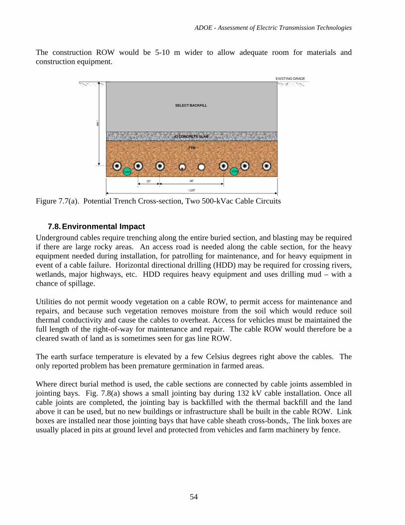
ADOE - Assessment of Electric Transmission Technologies
54
The construction ROW would be 5-10 m wider to allow adequate room for materials and construction equipment.
EXISTING GRADE
48”
SELECT BACKFILL
4? CONCRETE SLAB
FTB
~120”
16” 36”
COM2COM1
Figure 7.7(a). Potential Trench Cross-section, Two 500-kVac Cable Circuits
7.8. Environmental Impact Underground cables require trenching along the entire buried section, and blasting may be required if there are large rocky areas. An access road is needed along the cable section, for the heavy equipment needed during installation, for patrolling for maintenance, and for heavy equipment in event of a cable failure. Horizontal directional drilling (HDD) may be required for crossing rivers, wetlands, major highways, etc. HDD requires heavy equipment and uses drilling mud – with a chance of spillage. Utilities do not permit woody vegetation on a cable ROW, to permit access for maintenance and repairs, and because such vegetation removes moisture from the soil which would reduce soil thermal conductivity and cause the cables to overheat. Access for vehicles must be maintained the full length of the right-of-way for maintenance and repair. The cable ROW would therefore be a cleared swath of land as is sometimes seen for gas line ROW. The earth surface temperature is elevated by a few Celsius degrees right above the cables. The only reported problem has been premature germination in farmed areas. Where direct burial method is used, the cable sections are connected by cable joints assembled in jointing bays. Fig. 7.8(a) shows a small jointing bay during 132 kV cable installation. Once all cable joints are completed, the jointing bay is backfilled with the thermal backfill and the land above it can be used, but no new buildings or infrastructure shall be built in the cable ROW. Link boxes are installed near those jointing bays that have cable sheath cross-bonds,. The link boxes are usually placed in pits at ground level and protected from vehicles and farm machinery by fence.
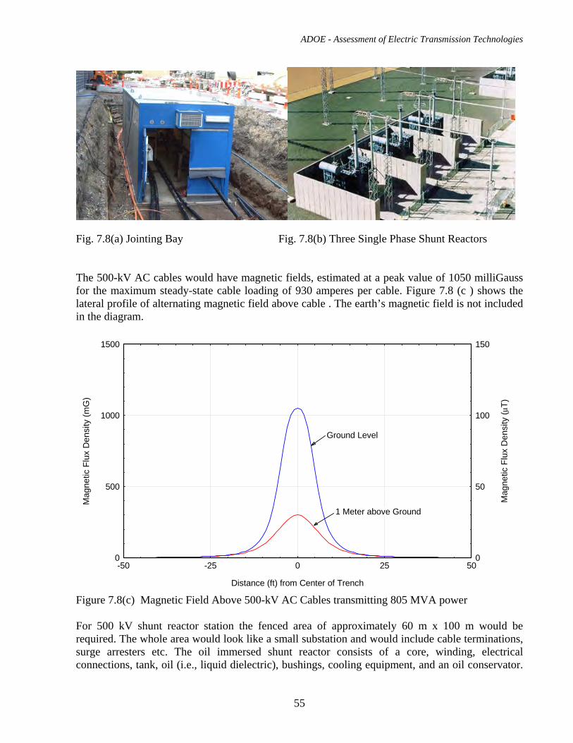
ADOE - Assessment of Electric Transmission Technologies
55
Fig. 7.8(a) Jointing Bay Fig. 7.8(b) Three Single Phase Shunt Reactors The 500-kV AC cables would have magnetic fields, estimated at a peak value of 1050 milliGauss for the maximum steady-state cable loading of 930 amperes per cable. Figure 7.8 (c ) shows the lateral profile of alternating magnetic field above cable . The earth’s magnetic field is not included in the diagram.
0
500
1000
1500
-50 -25 0 25 500
50
100
150
1 Meter above Ground
Ground Level
Distance (ft) from Center of Trench
Mag
netic
Flu
x D
ensi
ty (m
G)
Mag
netic
Flu
x D
ensi
ty (μ
T)
Figure 7.8(c) Magnetic Field Above 500-kV AC Cables transmitting 805 MVA power For 500 kV shunt reactor station the fenced area of approximately 60 m x 100 m would be required. The whole area would look like a small substation and would include cable terminations, surge arresters etc. The oil immersed shunt reactor consists of a core, winding, electrical connections, tank, oil (i.e., liquid dielectric), bushings, cooling equipment, and an oil conservator.
ADOE - Assessment of Electric Transmission Technologies
56
Environmental consideration should include: landscaping to blend the station into surroundings, audible noise from the reactors and containment and prevention of oil spills.
7.9. Operation and Maintenance The cable charging current would be a concern for utility system operations – in addition to the shunt reactors required to absorb charging currents, these currents may contribute to stability problems. Utilities typically do not re-close on a fault on a line that contains underground cables. Relaying would be required to block re-closing if a cable section were inserted into an overhead line. The 500-kV XLPE cables would require maintenance to help assure trouble-free operation. Maintenance items are summarized below:
• The terminations would probably be filled with a dielectric liquid or SF6 gas. Monitoring equipment would be required for in each transition station, and any leaks must be located and repaired.
• The terminations and all other exposed components need to be inspected periodically for electrical or mechanical problems. The porcelain terminations are attractive targets for rifle practice, but can be hidden behind walls or screens.
• The splices will have link boxes and sheath voltage limiters that are required to handle sheath currents and potential sheath overvoltages. These devices and the cable jacket protecting the sheath should be inspected and tested periodically. The sheath voltage limiters should be checked if there is a fault on the cable system or a through-fault involving the cables. Manholes, if used, would be inspected periodically for structural integrity.
• Periodic inspections are conducted along the full line length to insure there is no encroachment that might damage the cables.
7.10. Examples of Application
1.1.1. Shinkeiyo – Toyosu Line (Japan 2000) Voltage
Power
Circuit Length
Conductor
Manufacturer
500 kV
2 x 900 MW
40 km
Cu 2500 mm2
4 (JPN)
This project is a world first; in that it is the first time that 500 kV XLPE cable has been used for long distance transmission, and hence involves the use of a significant number of splices. It is also significant in that it is the longest AC underground transmission line in Japan. The 40 km, double circuit line connects with the 500 kV overhead power ring around Tokyo at the Shinkeiyo substation and delivers power to the Toyosu substation in the heart of the city. Almost the entire route is enclosed in a custom-built cable tunnel, with the exception of duct installations under
ADOE - Assessment of Electric Transmission Technologies
57
bridges and elevated expressways. For cable installation in a 15km long tunnel section, which had sea access, the cables were transported by ship in 1800m lengths using special reels. For the remainder of the route where sea access was not possible cable was delivered by sea as near as possible to the site and transferred from reels to a special trailer. In this way delivery to site of lengths of 1200m was possible. Because of its long circuit length reactive compensation was installed at both ends.
1.1.2. Metropolitan Power Project: Copenhagen South Link (Denmark 1998) Voltage
Power
Circuit Length
Conductor
Manufacturer
400 kV
1000 MVA
35 km
Cu 1600 mm2
NKT (DEN)
This project was the world’s first significant application of XLPE cables at 400 kV. The cables were supplied and installed by NKT and the South Link was commissioned in 1998 followed by a shorter North Link in 1999. The total circuit length was 36km (14 km North Link and 22 km South Link) and a total of 123 prefabricated splices were utilized. 75 of the splices were supplied by Furukawa (JPN) and 22 by Prysmian (Italy). The origin of the remaining 26 splices is not known. The project is also significant in that it was direct buried.
1.1.3. Elstree – St. Johns Wood (UK – 2004) Voltage
Power
Circuit Length
Conductor
Manufacturer
400 kV
1200 MW
20 km
Cu 2500 mm2
SudKabel
The National Grid Co. of the UK undertook a major 400 kV XLPE cable project in the London area of the UK. A double circuit of 400 kV XLPE cables was installed in a purpose built 20 km long tunnel connecting an existing substation at Elstree in northwest London with a new substation in St. Johns Wood in central London. The project is one of the longest and highest rated 400 KV XLPE project yet built in Europe. The tunnel is 3m in diameter with five intermediate tunnel access shafts and head house buildings will be sited along the route. These buildings will be needed for tunnel ventilation purposes and to contain control equipment for the operation of the transmission cables.
The full thermal rating of the cables will be guaranteed by the use of forced air circulation within the tunnel which is divided into six sections (corresponding to the above mentioned ventilation shafts) for this purpose.
Operating temperatures in the tunnel and fire detection services will be provided by fiber optic systems, as will all system protection requirements.
ADOE - Assessment of Electric Transmission Technologies
58
The decision by the National Grid Co., traditionally a very conservative utility, to use 400 kV XLPE cable systems is an indication that such systems “have come of age.”
1.1.4. Barajas Airport Extension (Spain 2004) Voltage
Power
Circuit Length
Conductor
Manufacturer
400 kV
2 x 600 MW
13 km
Cu 2500 mm2
Prysmian
The existing 400 kV, 1200 MW overhead line that crossed an area required for the extension of the main runways at the Barajas Airport in Madrid. The solution was to replace the lines with 13 km of underground cable in a purpose-built cable tunnel under the new runways. The tunnel is of interest since it is constructed in relatively short pre-cast concrete sections, which are installed in an excavated trench, which is subsequently backfilled. The tunnel has forced air ventilation for cable cooling and the cables are thermally monitored using DTS (differential temperature sensing) systems with optical fibers attached to the surface of each of the cables.
1.1.5. Shanghai City 500 kV Project (CHINA, Current) Voltage
Power
Circuit Length
Conductor
Manufacturer
500 kV
~600 MW
17 km
Cu 2500 mm2
Nexans and Viscas
This project which is currently under construction will follow the current trend in that the cables will be installed in a purpose- built tunnel, in this case with a diameter of 3.5 m. Two cable circuits will be installed, one supplied by Nexans and other supplied by Viscas. The cables will be delivered to site in lengths of approximately 600 m. Approximately 80 splices and 6 cable terminations will be installed per each circuit. The project is expected to be commissioned in 2010.
8. AC Overhead Line Combined with Underground Transmission Cable
8.1. Description of the technology and available suppliers for materials In the areas where the transmission capacity is already constrained by thermal limits of transmission lines and where re-conductoring of existing lines is not feasible, the construction of new transmission line is the only solution to meet the increased power demand and maintain the transmission grid reliability. However, new overhead transmission lines may be difficult to
ADOE - Assessment of Electric Transmission Technologies
59
construct in the densely built-up areas. In such cases, placing a critical section of the transmission line underground is an option . The illustration of the combined overhead and underground line is shown as Case 8 in Fig. 16.4(a). The examples of application of this technology are given in section 8.9. Where possible, cables are buried in a trench as shown in Fig. 7.7(a) or in concrete duct banks as shown in Fig. 8.6(a). In the built-up areas, tunnels are built using modern tunnel boring technology to minimize the impact to the infrastructure above the tunnel line. Transition stations to connect the overhead line to underground cables have to be built at both ends of underground cable section. The description of the overhead and underground transmission line technology and list of available suppliers for materials are given in the sections 6. and 7.
8.2. Transition Stations Transition stations contain dead end tension tower, down-droppers, gantry structure, lightning arresters, line post insulators, disconnect switches, grounding switches, cable terminations, grounding system, lightning poles, control building, fence etc. Depending on the properties of the surrounding transmission system and the length of underground portion of the line, shunt reactors may be required in some transition stations. The reactors require proper protection, therefore, in such stations voltage transformers, current transformers, relay protection systems and additional surge arresters shall be installed, Fig. 8.2(a) to Fig. 8.2(d) show the layouts of transition stations without and with shunt reactors.
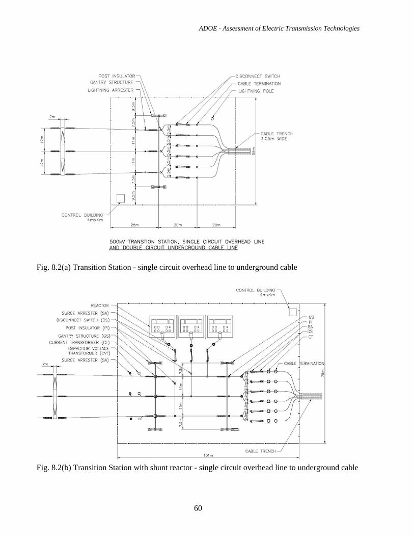
ADOE - Assessment of Electric Transmission Technologies
60
Fig. 8.2(a) Transition Station - single circuit overhead line to underground cable
Fig. 8.2(b) Transition Station with shunt reactor - single circuit overhead line to underground cable
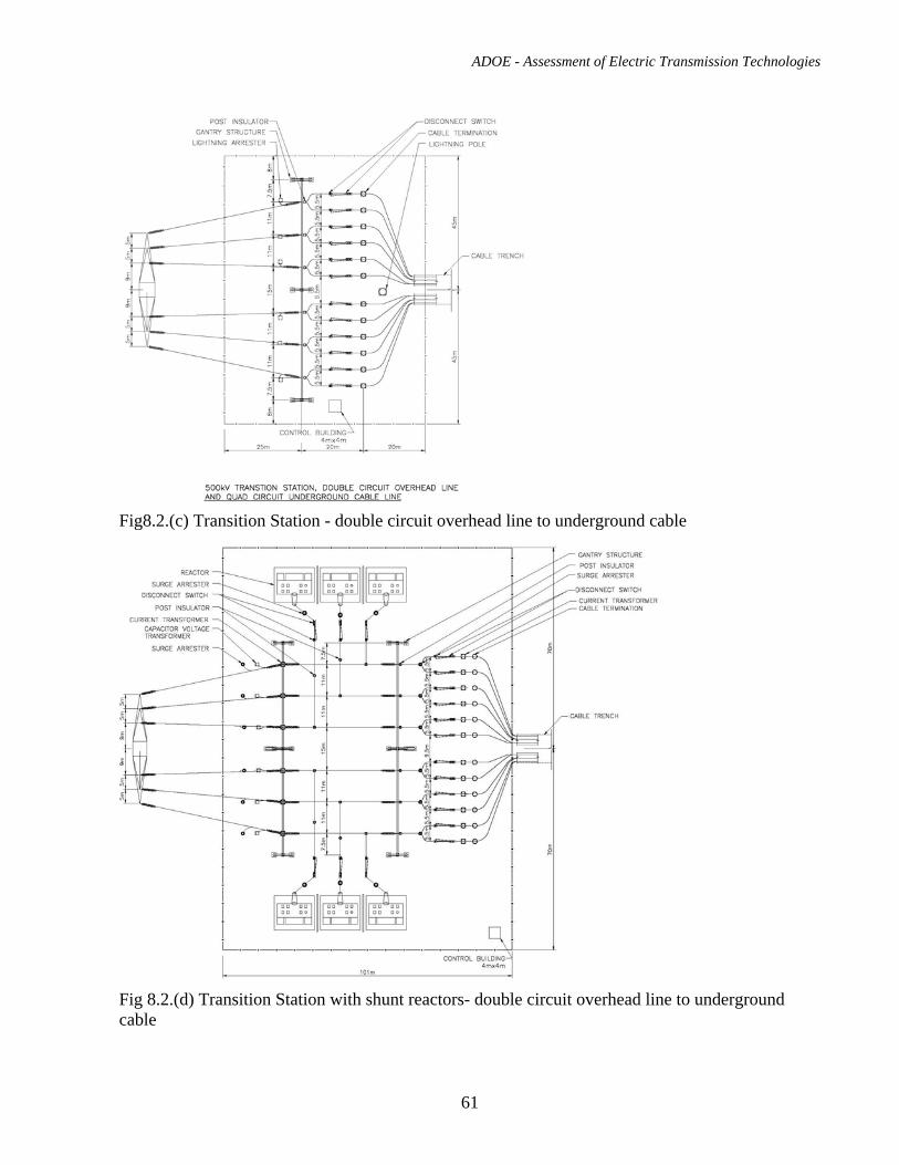
ADOE - Assessment of Electric Transmission Technologies
61
Fig8.2.(c) Transition Station - double circuit overhead line to underground cable
Fig 8.2.(d) Transition Station with shunt reactors- double circuit overhead line to underground cable
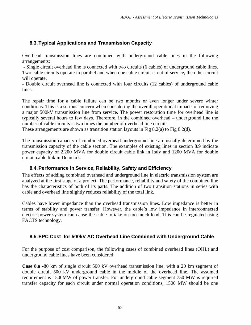
ADOE - Assessment of Electric Transmission Technologies
62
8.3. Typical Applications and Transmission Capacity Overhead transmission lines are combined with underground cable lines in the following arrangements: - Single circuit overhead line is connected with two circuits (6 cables) of underground cable lines. Two cable circuits operate in parallel and when one cable circuit is out of service, the other circuit will operate. - Double circuit overhead line is connected with four circuits (12 cables) of underground cable lines. The repair time for a cable failure can be two months or even longer under severe winter conditions. This is a serious concern when considering the overall operational impacts of removing a major 500kV transmission line from service. The power restoration time for overhead line is typically several hours to few days. Therefore, in the combined overhead – underground line the number of cable circuits is two times the number of overhead line circuits. These arrangements are shown as transition station layouts in Fig 8.2(a) to Fig 8.2(d). The transmission capacity of combined overhead-underground line are usually determined by the transmission capacity of the cable section. The examples of existing lines in section 8.9 indicate power capacity of 2,200 MVA for double circuit cable link in Italy and 1200 MVA for double circuit cable link in Denmark.
8.4. Performance in Service, Reliability, Safety and Efficiency The effects of adding combined overhead and underground line in electric transmission system are analyzed at the first stage of a project. The performance, reliability and safety of the combined line has the characteristics of both of its parts. The addition of two transition stations in series with cable and overhead line slightly reduces reliability of the total link. Cables have lower impedance than the overhead transmission lines. Low impedance is better in terms of stability and power transfer. However, the cable’s low impedance in interconnected electric power system can cause the cable to take on too much load. This can be regulated using FACTS technology.
8.5. EPC Cost for 500kV AC Overhead Line Combined with Underground Cable For the purpose of cost comparison, the following cases of combined overhead lines (OHL) and underground cable lines have been considered: Case 8.a -80 km of single circuit 500 kV overhead transmission line, with a 20 km segment of double circuit 500 kV underground cable in the middle of the overhead line. The assumed requirement is 1500MW of power transfer. For underground cable segment 750 MW is required transfer capacity for each circuit under normal operation conditions, 1500 MW should be one
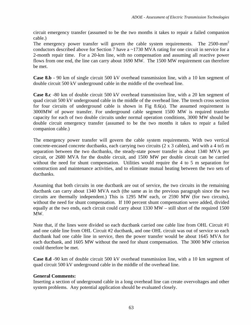
ADOE - Assessment of Electric Transmission Technologies
63
circuit emergency transfer (assumed to be the two months it takes to repair a failed companion cable.) The emergency power transfer will govern the cable system requirements. The 2500-mm2 conductors described above for Section 7 have a ~1730 MVA rating for one circuit in service for a 2-month repair time. For a 20-km line, with no compensation and assuming all reactive power flows from one end, the line can carry about 1690 MW. The 1500 MW requirement can therefore be met. Case 8.b - 90 km of single circuit 500 kV overhead transmission line, with a 10 km segment of double circuit 500 kV underground cable in the middle of the overhead line. Case 8.c -80 km of double circuit 500 kV overhead transmission line, with a 20 km segment of quad circuit 500 kV underground cable in the middle of the overhead line. The trench cross section for four circuits of underground cable is shown in Fig 8.6(a). The assumed requirement is 3000MW of power transfer. For underground cable segment 1500 MW is required transfer capacity for each of two double circuits under normal operation conditions, 3000 MW should be double circuit emergency transfer (assumed to be the two months it takes to repair a failed companion cable.) The emergency power transfer will govern the cable system requirements. With two vertical concrete-encased concrete ductbanks, each carrying two circuits (2 x 3 cables), and with a 4 to5 m separation between the two ductbanks, the steady-state power transfer is about 1340 MVA per circuit, or 2680 MVA for the double circuit, and 1500 MW per double circuit can be carried without the need for shunt compensation. Utilities would require the 4 to 5 m separation for construction and maintenance activities, and to eliminate mutual heating between the two sets of ductbanks. Assuming that both circuits in one ductbank are out of service, the two circuits in the remaining ductbank can carry about 1340 MVA each (the same as in the previous paragraph since the two circuits are thermally independent.) This is 1295 MW each, or 2590 MW (for two circuits), without the need for shunt compensation. If 100 percent shunt compensation were added, divided equally at the two ends, each circuit could carry about 1330 MW – still short of the required 1500 MW. Note that, if the lines were divided so each ductbank carried one cable line from OHL Circuit #1 and one cable line from OHL Circuit #2 ductbank, and one OHL circuit was out of service so each ductbank had one cable line in service, then the power transfer would be about 1645 MVA for each ductbank, and 1605 MW without the need for shunt compensation. The 3000 MW criterion could therefore be met. Case 8.d -90 km of double circuit 500 kV overhead transmission line, with a 10 km segment of quad circuit 500 kV underground cable in the middle of the overhead line. General Comments: Inserting a section of underground cable in a long overhead line can create overvoltages and other system problems. Any potential application should be evaluated closely.
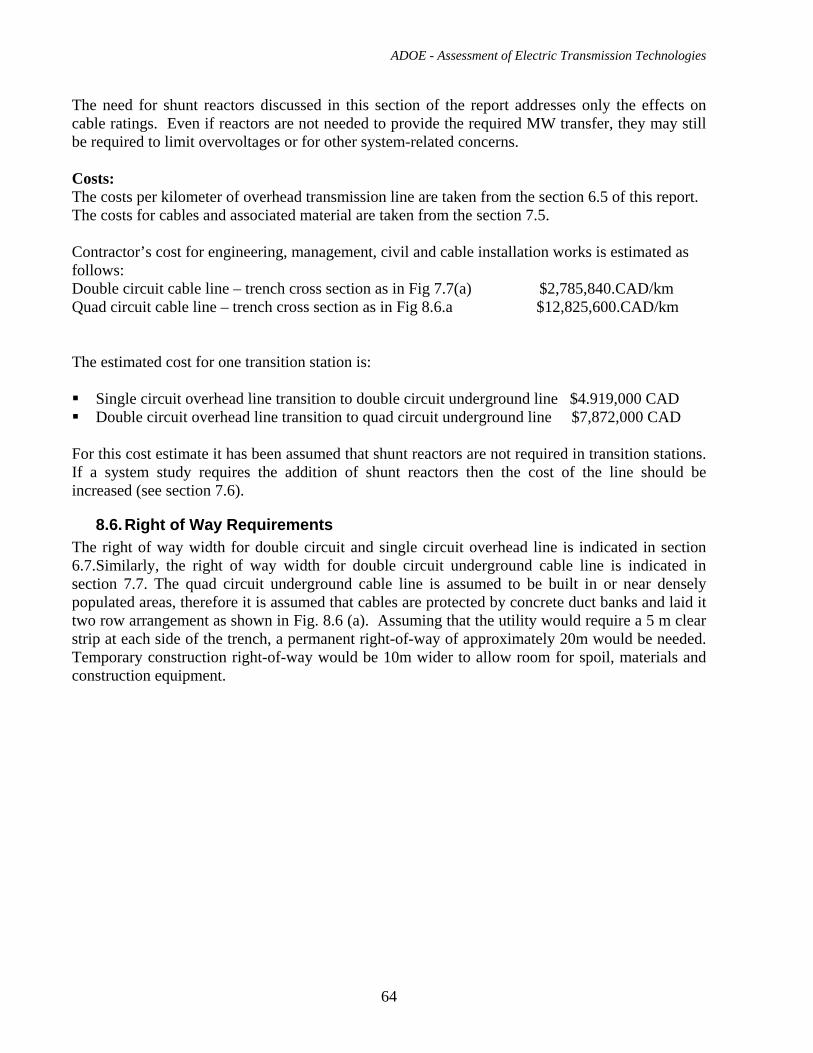
ADOE - Assessment of Electric Transmission Technologies
64
The need for shunt reactors discussed in this section of the report addresses only the effects on cable ratings. Even if reactors are not needed to provide the required MW transfer, they may still be required to limit overvoltages or for other system-related concerns. Costs: The costs per kilometer of overhead transmission line are taken from the section 6.5 of this report. The costs for cables and associated material are taken from the section 7.5. Contractor’s cost for engineering, management, civil and cable installation works is estimated as follows: Double circuit cable line – trench cross section as in Fig 7.7(a) $2,785,840.CAD/km Quad circuit cable line – trench cross section as in Fig 8.6.a $12,825,600.CAD/km The estimated cost for one transition station is: Single circuit overhead line transition to double circuit underground line $4.919,000 CAD Double circuit overhead line transition to quad circuit underground line $7,872,000 CAD
For this cost estimate it has been assumed that shunt reactors are not required in transition stations. If a system study requires the addition of shunt reactors then the cost of the line should be increased (see section 7.6).
8.6. Right of Way Requirements The right of way width for double circuit and single circuit overhead line is indicated in section 6.7.Similarly, the right of way width for double circuit underground cable line is indicated in section 7.7. The quad circuit underground cable line is assumed to be built in or near densely populated areas, therefore it is assumed that cables are protected by concrete duct banks and laid it two row arrangement as shown in Fig. 8.6 (a). Assuming that the utility would require a 5 m clear strip at each side of the trench, a permanent right-of-way of approximately 20m would be needed. Temporary construction right-of-way would be 10m wider to allow room for spoil, materials and construction equipment.
ADOE - Assessment of Electric Transmission Technologies
65
Fig 8.6(a) Trench arrangement for four circuit underground transmission line
8.7. Environmental Impact For the combined overhead and underground line see the relevant sections: 6.8 ( for overhead line) and 7.8 (for underground cable). In addition to that, the impact of building two transition stations should be considered. For undergrounding 500kV double circuit overhead line the size of each transition station should be 65m x 90m approximately. If shunt reactors have to be included, the size of each transition station should be 100 m x 140 m approximately. Environmental consideration for transition station should include: landscaping to blend the station into suroundings, audible noise from the high voltage equipment and containment and prevention of oil spills.
8.8. Operation and Maintenance For the combined overhead and underground line see the relevant sections: 6.9 ( for overhead line) and 7.9 (for underground cable). The transition stations between overhead and underground portions of the line require similar maintenance as the standard substations.
8.9. Examples of Application
The connection of No. 904L 240 kV overhead line at EPCOR’s Argyll Transfer Station to underground cable circuits No, 240BA2 and 240BA3 is an example of combined overhead/underground line in the City of Edmonton.
400kV double circuit transmission line Lackenby - Picton – Shipton in UK is 75 km long and it has an underground cable section that is 6km long between Nunthorpe and Newby. The
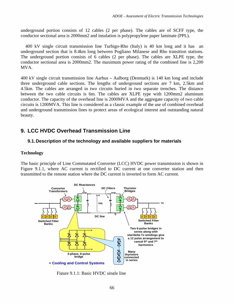
ADOE - Assessment of Electric Transmission Technologies
66
underground portion consists of 12 cables (2 per phase). The cables are of SCFF type, the conductor sectional area is 2000mm2 and insulation is polypropylene paper laminate (PPL).
400 kV single circuit transmission line Turbigo-Rho (Italy) is 40 km long and it has an underground section that is 8.4km long between Pogliano Milanese and Rho transition stations. The underground portion consists of 6 cables (2 per phase). The cables are XLPE type, the conductor sectional area is 2000mm2. The maximum power rating of the combined line is 2,200 MVA. 400 kV single circuit transmission line Aarhus – Aalborg (Denmark) is 140 km long and include three underground cable sections. The lengths of underground sections are 7 km, 2.5km and 4.5km. The cables are arranged in two circuits buried in two separate trenches. The distance between the two cable circuits is 6m. The cables are XLPE type with 1200mm2 aluminum conductor. The capacity of the overhead line is 2000MVA and the aggregate capacity of two cable circuits is 1200MVA. This line is considered as a classic example of the use of combined overhead and underground transmission lines to protect areas of ecological interest and outstanding natural beauty.
9. LCC HVDC Overhead Transmission Line
9.1. Description of the technology and available suppliers for materials Technology The basic principle of Line Commutated Converter (LCC) HVDC power transmission is shown in Figure 9.1.1, where AC current is rectified to DC current at one converter station and then transmitted to the remote station where the DC current is inverted to form AC current.
FF FFFF FF
~ ~
Converter Transformers
DC Reactances
DC lineSwitched Filter
Banks
Many thyristors connected in series
3-phase, 6-pulse bridge
Thyristor Bridges
Switched Filter Banks
FF FFFF FF
DC Filters
+
_
Vdc
Two 6-pulse bridges in series along with
star/delta Tx windings give a 12 pulse arrangement to
cancel 5th and 7th
harmonics
+ Cooling and Control Systems
Figure 9.1.1: Basic HVDC single line
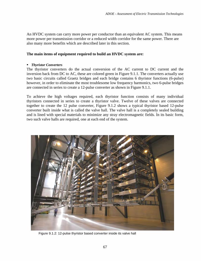
ADOE - Assessment of Electric Transmission Technologies
67
An HVDC system can carry more power per conductor than an equivalent AC system. This means more power per transmission corridor or a reduced width corridor for the same power. There are also many more benefits which are described later in this section.
The main items of equipment required to build an HVDC system are:
Thyristor Converters The thyristor converters do the actual conversion of the AC current to DC current and the inversion back from DC to AC, these are colored green in Figure 9.1.1. The converters actually use two basic circuits called Graetz bridges and each bridge contains 6 thyristor functions (6-pulse) however, in order to eliminate the most troublesome low frequency harmonics, two 6-pulse bridges are connected in series to create a 12-pulse converter as shown in Figure 9.1.1. To achieve the high voltages required, each thyristor function consists of many individual thyristors connected in series to create a thyristor valve. Twelve of these valves are connected together to create the 12 pulse converter, Figure 9.1.2 shows a typical thyristor based 12-pulse converter built inside what is called the valve hall. The valve hall is a completely sealed building and is lined with special materials to minimize any stray electromagnetic fields. In its basic form, two such valve halls are required, one at each end of the system.
Figure 9.1.2: 12-pulse thyristor based converter inside its valve hall
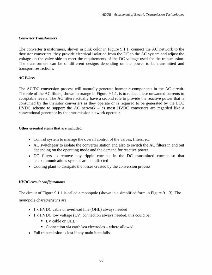
ADOE - Assessment of Electric Transmission Technologies
68
Converter Transformers
The converter transformers, shown in pink color in Figure 9.1.1, connect the AC network to the thyristor converters, they provide electrical isolation from the DC to the AC system and adjust the voltage on the valve side to meet the requirements of the DC voltage used for the transmission. The transformers can be of different designs depending on the power to be transmitted and transport restrictions. AC Filters
The AC/DC conversion process will naturally generate harmonic components in the AC circuit. The role of the AC filters, shown in orange in Figure 9.1.1, is to reduce these unwanted currents to acceptable levels. The AC filters actually have a second role to provide the reactive power that is consumed by the thyristor converters as they operate or is required to be generated by the LCC HVDC scheme to support the AC network – as most HVDC converters are regarded like a conventional generator by the transmission network operator.
Other essential items that are included:
• Control system to manage the overall control of the valves, filters, etc • AC switchgear to isolate the converter station and also to switch the AC filters in and out
depending on the operating mode and the demand for reactive power. • DC filters to remove any ripple currents in the DC transmitted current so that
telecommunications systems are not affected • Cooling plant to dissipate the losses created by the conversion process
HVDC circuit configurations
The circuit of Figure 9.1.1 is called a monopole (shown in a simplified form in Figure 9.1.3). The
monopole characteristics are: ,
• 1 x HVDC cable or overhead line (OHL) always needed • 1 x HVDC low voltage (LV) connection always needed, this could be:
LV cable or OHL Connection via earth/sea electrodes – where allowed
• Full transmission is lost if any main item fails
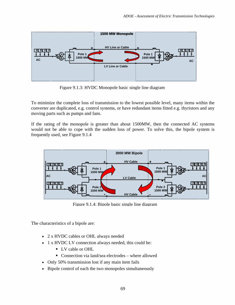
ADOE - Assessment of Electric Transmission Technologies
69
To minimize the complete loss of transmission to the lowest possible level, many items within the converter are duplicated, e.g. control systems, or have redundant items fitted e.g. thyristors and any moving parts such as pumps and fans. If the rating of the monopole is greater than about 1500MW, then the connected AC systems would not be able to cope with the sudden loss of power. To solve this, the bipole system is frequently used, see Figure 9.1.4
The characteristics of a bipole are:
• 2 x HVDC cables or OHL always needed • 1 x HVDC LV connection always needed, this could be:
LV cable or OHL Connection via land/sea electrodes – where allowed
• Only 50% transmission lost if any main item fails • Bipole control of each the two monopoles simultaneously
Figure 9.1.3: HVDC Monopole basic single line diagram
1500 MW Monopole
FF F FFF F FPole 1
1500 MWPole 1
1500 MWAC
HV Line or Cable
LV Line or Cable
AC
+ +
1500 MW Monopole1500 MW Monopole
FF F FFF F FPole 1
1500 MWPole 1
1500 MWAC
HV Line or Cable
LV Line or Cable
AC
+ +
FF F FFF F F
FF F FFF F F
3000 MW Bipole
Pole 11500 MW
Pole 11500 MW
Pole 21500 MW
Pole 21500 MW
HV Cable
LV Cable
HV Cable
AC AC
+ +
- -
FF F FFF F F
FF F FFF F F
3000 MW Bipole
Pole 11500 MW
Pole 11500 MW
Pole 21500 MW
Pole 21500 MW
HV Cable
LV Cable
HV Cable
AC AC
+ +
- -
FF F FFF F F
F
FF F FFF F F
FF F FFF F FF F FFF F F
3000 MW Bipole
Pole 11500 MW
Pole 11500 MW
Pole 21500 MW
Pole 21500 MW
HV Cable
LV Cable
HV Cable
AC AC
+ +
- -
Figure 9.1.4: Bipole basic single line diagram
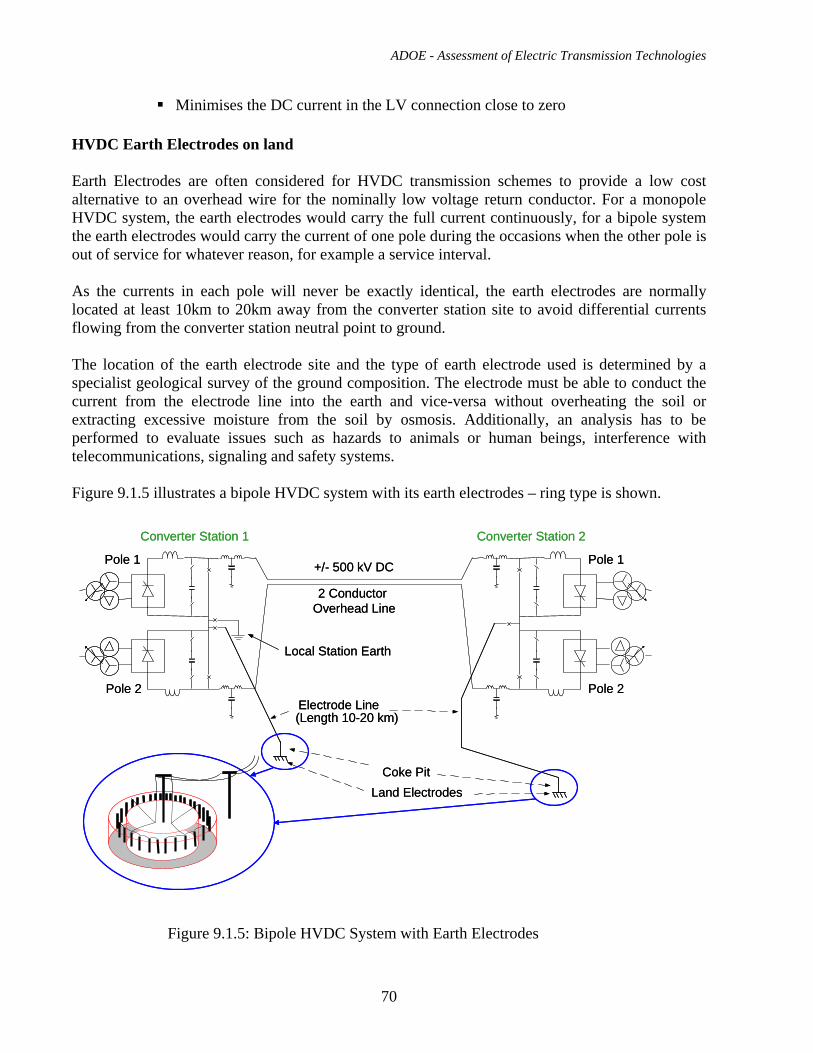
ADOE - Assessment of Electric Transmission Technologies
70
Minimises the DC current in the LV connection close to zero
HVDC Earth Electrodes on land Earth Electrodes are often considered for HVDC transmission schemes to provide a low cost alternative to an overhead wire for the nominally low voltage return conductor. For a monopole HVDC system, the earth electrodes would carry the full current continuously, for a bipole system the earth electrodes would carry the current of one pole during the occasions when the other pole is out of service for whatever reason, for example a service interval. As the currents in each pole will never be exactly identical, the earth electrodes are normally located at least 10km to 20km away from the converter station site to avoid differential currents flowing from the converter station neutral point to ground. The location of the earth electrode site and the type of earth electrode used is determined by a specialist geological survey of the ground composition. The electrode must be able to conduct the current from the electrode line into the earth and vice-versa without overheating the soil or extracting excessive moisture from the soil by osmosis. Additionally, an analysis has to be performed to evaluate issues such as hazards to animals or human beings, interference with telecommunications, signaling and safety systems. Figure 9.1.5 illustrates a bipole HVDC system with its earth electrodes – ring type is shown.
Figure 9.1.5: Bipole HVDC System with Earth Electrodes
Local Station Earth
Land Electrodes
Electrode Line(Length 10-20 km)
Coke Pit
+/- 500 kV DC
2 Conductor Overhead Line
Pole 1
Pole 2
Pole 1
Pole 2
Converter Station 1 Converter Station 2
Local Station Earth
Land Electrodes
Electrode Line(Length 10-20 km)
Coke Pit
+/- 500 kV DC
2 Conductor Overhead Line
Pole 1
Pole 2
Pole 1
Pole 2
Converter Station 1 Converter Station 2
ADOE - Assessment of Electric Transmission Technologies
71
The midpoint of the two converter poles are usually connected to the earth electrodes by an overhead line with a voltage rating of about 10kV and a current rating equal to the HVDC scheme pole rating. The materials that are used for the electrodes will depend on the application and the electrochemical reactions that can be expected at ground surface.
For a Cathode: the current passes from the surroundings into the electrode surface, this leads to water molecules and oxygen being reduced, i.e. supplied with electrons.
For an Anode: the current passes from the electrode surface out to the surroundings, this leads to negatively charged ions and water molecules being oxidized, i.e. release electrons. This causes consumption of unstable electrode material, therefore inert materials must be used.
For permanent operation as either anode or as cathode:
Titanium can be used as anode Copper used as cathode
In a balanced Bipole with limited exposure to Monopolar operation
Titanium may be used both as anode and cathode Copper electrodes are restricted to cathode operation only
For a fully reversible operation, the following materials can be used: Graphite / Coke Magnetite and high-silicon Iron
In all cases graphite/coke will be used as the conductive medium between the electrode material and the earth. There are three different ground electrode designs that are normally considered: Ring This is illustrated in Figure 9.1.5 and Figure 9.1.6. Figure 9.1.6 shows an example from Manitoba Hydro’s Nelson River HVDC project. The diameter of the ring shown in the figure is approximately 300m, and no fence has been installed. At sites where fence is installed, the clearance from the ring to the security fence is typically around 30m to 35m.

ADOE - Assessment of Electric Transmission Technologies
72
Figure 9.1.6: Ring Earth Electrode site The ring earth electrode is the option mostly chosen, as it is usually the lowest cost and the simplest to design and construct. Horizontal This is used where a sufficiently large area of land is available with homogeneous ground characteristics close to surface. Figure 9.1.7 illustrates the cross section of a horizontal earth electrode system. A conductor, which can have many different shapes from round through to star, is buried some 2 to 3 meters below ground in a bed of coke. This is protected by a layer of stone with earth fill up to ground level.
Figure 9.1.7: Horizontal Earth Electrode structure
Earth Fill
Stone
Coke bedElectrode
Earth Fill
Stone
Coke bedElectrode
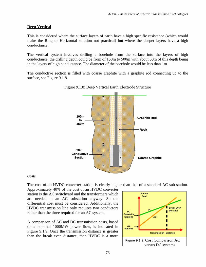
ADOE - Assessment of Electric Transmission Technologies
73
Deep Vertical This is considered where the surface layers of earth have a high specific resistance (which would make the Ring or Horizontal solution not practical) but where the deeper layers have a high conductance. The vertical system involves drilling a borehole from the surface into the layers of high conductance, the drilling depth could be from of 150m to 500m with about 50m of this depth being in the layers of high conductance. The diameter of the borehole would be less than 1m. The conductive section is filled with coarse graphite with a graphite rod connecting up to the surface, see Figure 9.1.8.
Figure 9.1.8: Deep Vertical Earth Electrode Structure
Costs
The cost of an HVDC converter station is clearly higher than that of a standard AC sub-station. Approximately 40% of the cost of an HVDC converter station is the AC switchyard and the transformers which are needed in an AC substation anyway. So the differential cost must be considered. Additionally, the HVDC transmission line only requires two conductors rather than the three required for an AC system. A comparison of AC and DC transmission costs, based on a nominal 1000MW power flow, is indicated in Figure 9.1.9. Once the transmission distance is greater than the break even distance, then HVDC is a more
StationCost
DCConvertorStations
ACStations
DC
AC
Break EvenDistance
TransmissionDistance
StationCost
DCConvertorStations
ACStations
DC
AC
Break EvenDistance
Transmission Distance
StationCost
DCConvertorStations
ACStations
DC
AC
Break EvenDistance
TransmissionDistance
StationCost
DCConvertorStations
ACStations
DC
AC
Break EvenDistance
Transmission Distance
Figure 9.1.9: Cost Comparison AC versus DC systems
Graphite Rod
Rock
Coarse Graphite
50m Conductive
Section
100mto
450m
Graphite Rod
Rock
Coarse Graphite
50m Conductive
Section
100mto
450m
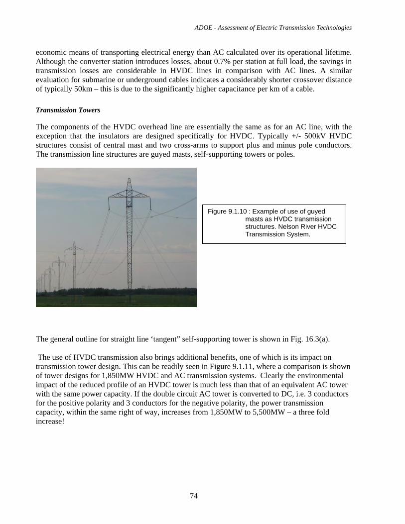
ADOE - Assessment of Electric Transmission Technologies
74
economic means of transporting electrical energy than AC calculated over its operational lifetime. Although the converter station introduces losses, about 0.7% per station at full load, the savings in transmission losses are considerable in HVDC lines in comparison with AC lines. A similar evaluation for submarine or underground cables indicates a considerably shorter crossover distance of typically 50km – this is due to the significantly higher capacitance per km of a cable.
Transmission Towers
The components of the HVDC overhead line are essentially the same as for an AC line, with the exception that the insulators are designed specifically for HVDC. Typically +/- 500kV HVDC structures consist of central mast and two cross-arms to support plus and minus pole conductors. The transmission line structures are guyed masts, self-supporting towers or poles.
The general outline for straight line ‘tangent” self-supporting tower is shown in Fig. 16.3(a). The use of HVDC transmission also brings additional benefits, one of which is its impact on transmission tower design. This can be readily seen in Figure 9.1.11, where a comparison is shown of tower designs for 1,850MW HVDC and AC transmission systems. Clearly the environmental impact of the reduced profile of an HVDC tower is much less than that of an equivalent AC tower with the same power capacity. If the double circuit AC tower is converted to DC, i.e. 3 conductors for the positive polarity and 3 conductors for the negative polarity, the power transmission capacity, within the same right of way, increases from 1,850MW to 5,500MW – a three fold increase!
Figure 9.1.10 : Example of use of guyed masts as HVDC transmission structures. Nelson River HVDC Transmission System.
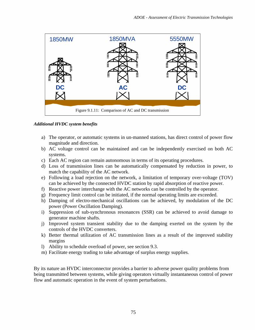
ADOE - Assessment of Electric Transmission Technologies
75
Additional HVDC system benefits
a) The operator, or automatic systems in un-manned stations, has direct control of power flow magnitude and direction.
b) AC voltage control can be maintained and can be independently exercised on both AC systems.
c) Each AC region can remain autonomous in terms of its operating procedures. d) Loss of transmission lines can be automatically compensated by reduction in power, to
match the capability of the AC network. e) Following a load rejection on the network, a limitation of temporary over-voltage (TOV)
can be achieved by the connected HVDC station by rapid absorption of reactive power. f) Reactive power interchange with the AC networks can be controlled by the operator. g) Frequency limit control can be initiated, if the normal operating limits are exceeded. h) Damping of electro-mechanical oscillations can be achieved, by modulation of the DC
power (Power Oscillation Damping). i) Suppression of sub-synchronous resonances (SSR) can be achieved to avoid damage to
generator machine shafts. j) Improved system transient stability due to the damping exerted on the system by the
controls of the HVDC converters. k) Better thermal utilization of AC transmission lines as a result of the improved stability
margins l) Ability to schedule overload of power, see section 9.3. m) Facilitate energy trading to take advantage of surplus energy supplies.
By its nature an HVDC interconnector provides a barrier to adverse power quality problems from being transmitted between systems, while giving operators virtually instantaneous control of power flow and automatic operation in the event of system perturbations.
1850MW 1850MVA 5550MW
DCDC DCDCACAC
Figure 9.1.11: Comparison of AC and DC transmission
ADOE - Assessment of Electric Transmission Technologies
76
Available suppliers
Due to the massive research and development programs required to support an HVDC activity, as well as the breadth of experience beyond the power electronics aspects necessary to complete an HVDC scheme, there are very few suppliers of complete HVDC systems.
These suppliers are:
• ABB - based in Ludvika, Sweden – installed its first scheme in 1954
• AREVA – based in Stafford, UK - installed its first scheme in 1966
• Siemens – based in Erlangen, Germany – installed its first scheme in 1975
• Toshiba, Mitsubishi, Hitachi & Nisshin – consortia have been arranged by the Japanese government for some projects within Japan. Only Toshiba has HVDC experience outside Japan, this was for a small back-to-back scheme in the early 1990s called Uruguaiana connecting Brazil with Argentina.
9.2. Typical Applications and Transmission Capacity
The two main applications for HVDC are:
Efficient bulk power transfer, point-to-point over long distances using overhead lines or submarine cables
Interconnecting asynchronous regions together
Taps, to take power out of a point-to-point scheme along its length, are possible but only two schemes in the world have operated in such a configuration. The operation and control of a DC system with a tap is considerably more complex than a two terminal system. The more modern VSC HVDC, see sections 11 and 12 of this report, is much more suitable for taps and multi-terminal operations.
Typical Transmission Capacity:
Several +/-500kV, 3000MW overhead line point-to-point LCC HVDC schemes are in operation in various parts of the world, such a rating has been the de-facto standard for many years.
9.3. Performance in Service, Reliability, Safety and Efficiency
Performance
Operation Configuration modes:
Both stations can fully operate as either rectifier or inverter Power flow is possible in both directions
ADOE - Assessment of Electric Transmission Technologies
77
Active power will be the normal control mode of operation at the inverter (receiving station)
Overload:
Typical overload ratings are given below; however, specific ratings can be designed on a case-by-case basis:
30% for 5 seconds, without redundant cooling 10% continuous with redundant cooling 20% for 2 hours with redundant cooling 10% for 2 hours without redundant cooling
Reactive Power exchange:
To meet the specification set by the client, but +/-50% is typical
AC side harmonics:
THD (rms value of total harmonic distortion) up to 40th harmonic: <4.0%
Dn (distortion of any individual harmonic voltage): <3.0%
Minimum Power Flow:
The minimum power flow that can be achieved for any standard LCC HVDC scheme is between 5 and 7%. Lower power flow levels can be achieved by additional rating in some power equipment, leading to increased costs. Some projects have specified minimum power transfer settings of 3%.
Power Reversal:
Power reversal with an LCC HVDC occurs in 3 stages, which takes approximately 300ms to execute (note that the network will usually demand a much longer actual power reversal time):
1. Ramp power down to minimum power flow level 2. Wait while the control system changes operation modes 3. Ramp up in the opposite direction
Mode switching from Bipole to Monopole operation:
The switch from bipole to monopole operation is achieved purely by the operation of the thyristor valves, the transfer time is approximately 50ms.
Start-up and Shut-down:
LCC HVDC systems can be automated to the extent that they can normally operate totally unmanned, therefore the start-up and shut-down process does not require any on-site staff intervention, however, there must be a push-button initiation from a remote dispatch centre or similar.
ADOE - Assessment of Electric Transmission Technologies
78
Interferences:
The AC and DC filters and good grounding will suppress emissions at telephone frequencies. Power Line Carrier (PLC) interference is prevented by the PLC filter. Radio interference is prevented by good grounding, shielding and radio frequency filters.
Reliability:
Reliability is measured using the total scheme availability for operation from both forced and scheduled outages – taking into account the converter stations at both ends of the interconnecting line.
The bipole HVDC system is the appropriate choice of HVDC topology for applications where it is mandatory to have at least 50% power if an outage occurs. The bipole system is also sensible for all large rating HVDC schemes.
The reliability of an HVDC scheme is assured by design:
Redundancy of critical items of equipment, including: Thyristor levels in the each converter arm Complete control system (which has a “bumpless” transfer from the operating
channel to the redundant channel Cooling system components (Valves and transformers) Auxiliary power systems Components in the AC filters or complete AC filters
Well proven converter design Based on >40 years of experience
Supply of appropriate spares
For a monopole (excluding transmission line) the following reliability figures are typical:
Forced outage rate 3 outages per year
Forced unavailability 0.3 to 0.5%
Scheduled unavailability <1.0%
Availability 98.5%
For a bipole (excluding transmission line) the following figures are normal:
Forced outage rate 6 outages per year for 100% power 0.05 outages per year for a minimum of 50% power
Forced unavailability 0.6 to 1.0% for 100% power 0.003% for a minimum of 50% power
Scheduled unavailability <2.0% for 100% power
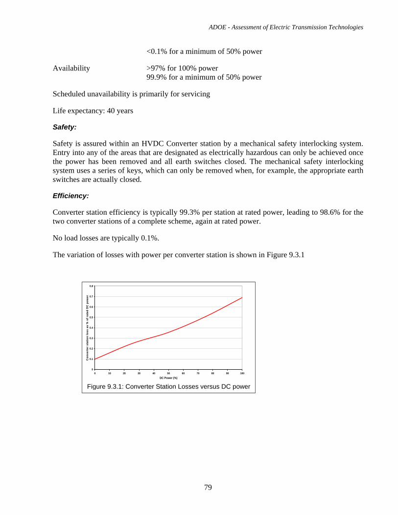
ADOE - Assessment of Electric Transmission Technologies
79
<0.1% for a minimum of 50% power
Availability >97% for 100% power 99.9% for a minimum of 50% power
Scheduled unavailability is primarily for servicing
Life expectancy: 40 years
Safety:
Safety is assured within an HVDC Converter station by a mechanical safety interlocking system. Entry into any of the areas that are designated as electrically hazardous can only be achieved once the power has been removed and all earth switches closed. The mechanical safety interlocking system uses a series of keys, which can only be removed when, for example, the appropriate earth switches are actually closed.
Efficiency:
Converter station efficiency is typically 99.3% per station at rated power, leading to 98.6% for the two converter stations of a complete scheme, again at rated power.
No load losses are typically 0.1%.
The variation of losses with power per converter station is shown in Figure 9.3.1
0
0.1
0.2
0.3
0.4
0.5
0.6
0.7
0.8
0 10 20 30 40 50 60 70 80 90 100DC Power (%)
Con
vert
er s
tatio
n lo
ss a
s %
of r
ated
DC
pow
er
Figure 9.3.1: Converter Station Losses versus DC power
ADOE - Assessment of Electric Transmission Technologies
80
9.4. EPC Cost for +/-500kV HVDC Overhead Transmission Line Engineering, procurement and construction (EPC) cost has been estimated for the case of +/- 500kV direct current bipolar overhead line. Latticed steel self-supporting towers carry two bundled conductors – one for each HVDC pole. It has been assumed that each bundled conductor consists of two sub-conductors: ACSR code name ‘Bluebird’. One shield wire is installed on top of the tower. The general outline for straight-line ‘tangent” tower is shown in Fig. 16.3(a). Although, for the purpose of this cost estimate, we have assumed twin conductor bundle, a more detailed analysis is required to decide if the three-conductor bundle would be more appropriate. Criteria such as conductor surface voltage gradient, power losses and overall line cost should be considered for a particular project. Power transmission capacity of the line is 3000MW. The transmission losses as the percentage of the rated power will be approximately 3.5% for 300km line and 7% for 600 km line. The estimated cost for +/-500kV HVDC overhead transmission line is: $762,000 CAD/km For HVDC transmission schemes with earth electrodes the cost of earth electrode system and electrode line should be considered. The typical cost would be up to about 7.5 millions CAD for each end of the HVDC line. If instead of earth electrode system, the insulated metallic neutral return is considered it would significantly increase the cost of the HVDC lines.
9.5. EPC Cost for +/-500kV LCC HVDC Converters
Full turnkey EPC cost for the converter stations for a typical OHL, +/-500kV bipole HVDC schemes current exchange rates are:
2000MW: ~$250 million CAD
3000MW: ~$330 million CAD
The losses per converter station at full load are approximately 0.7% of the rating.
9.6. Right of Way Requirements A HVDC overhead line requires less right-of –way width than the HVAC overhead line with equal power transmission capacity. Using similar criteria as those described in section 6.7 the width of right-of –way for +/-500kV HVDC overhead transmission line is estimated to be 54m approximately. When estimating the required amount of land for a HVDC transmission line the right-of –way for grounding electrode lines and area for electrode sites shall be also taken into account for HVDC transmission schemes without metallic return.
ADOE - Assessment of Electric Transmission Technologies
81
9.7. Environmental Impact Visual Impacts With respect to visual impacts, HVDC overhead transmission lines have several advantages over comparable HVAC lines. Direct current overhead lines require shorter towers and less material. HVDC lines are mostly bipolar and have two conductors. Single circuit AC transmission lines have three phase conductors. Audible noise levels at the converter station boundary fence: A typical noise level of 55dB(A) is measured at the boundary fence of a converter station that is not close to residential properties. However lower figures than this can be achieved by converter station layout, screening, enclosures and the use of low noise level equipment. HVDC converter station suppliers have extensive experience in this field. Normally the requirement for 40dB(A) at the nearest residence is achievable. Audible noise from HVDC transmission lines: The positive polarity conductor is the primary source of HVDC transmission line audible noise. Unlike AC lines, the noise levels decrease during foul weather. Typical levels of noise below an HVDC transmission line are 40dB(A) to 45dB(A) and they can be controlled by optimizing the design of conductor bundle, insulators and fittings. Radio Interference The radio interference from the high voltage transmission lines is caused mostly by the positive corona discharge. Therefore, radio interference is generated mainly by positive pole HVDC conductors, whereas with AC transmission line radio interference is created by all three phase conductors. For the equal levels of maximum electrical field intensity on the conductor surfaces the radio interference level of HVDC lines is 6-8 dB lower than of HVAC lines. Electromagnetic Fields The electric field produced by a HVDC transmission line is a sum of the electrostatic field created by the electric charge on conductors and the field due to the space charge produced by the line’s corona.. Fig. 9.7(a) shows the result of the calculation of the space charge-free electric field at ground level for the +/- 500 kV HVDC overhead transmission line that has been considered for the cost estimate described in the section 9.4.
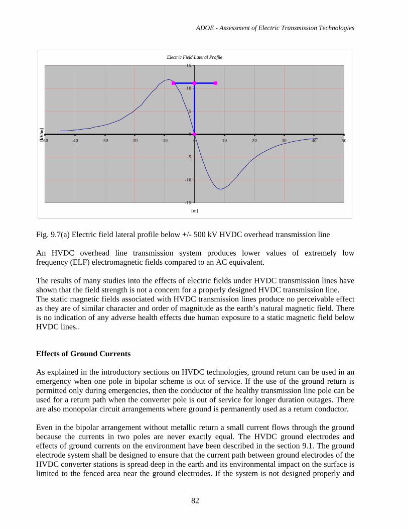
ADOE - Assessment of Electric Transmission Technologies
82
Electric Field Lateral Profile
-15
-10
-5
0
5
10
15
-50 -40 -30 -20 -10 0 10 20 30 40 50
[m]
[kV
/m]
Fig. 9.7(a) Electric field lateral profile below +/- 500 kV HVDC overhead transmission line An HVDC overhead line transmission system produces lower values of extremely low frequency (ELF) electromagnetic fields compared to an AC equivalent. The results of many studies into the effects of electric fields under HVDC transmission lines have shown that the field strength is not a concern for a properly designed HVDC transmission line. The static magnetic fields associated with HVDC transmission lines produce no perceivable effect as they are of similar character and order of magnitude as the earth’s natural magnetic field. There is no indication of any adverse health effects due human exposure to a static magnetic field below HVDC lines.. Effects of Ground Currents As explained in the introductory sections on HVDC technologies, ground return can be used in an emergency when one pole in bipolar scheme is out of service. If the use of the ground return is permitted only during emergencies, then the conductor of the healthy transmission line pole can be used for a return path when the converter pole is out of service for longer duration outages. There are also monopolar circuit arrangements where ground is permanently used as a return conductor. Even in the bipolar arrangement without metallic return a small current flows through the ground because the currents in two poles are never exactly equal. The HVDC ground electrodes and effects of ground currents on the environment have been described in the section 9.1. The ground electrode system shall be designed to ensure that the current path between ground electrodes of the HVDC converter stations is spread deep in the earth and its environmental impact on the surface is limited to the fenced area near the ground electrodes. If the system is not designed properly and
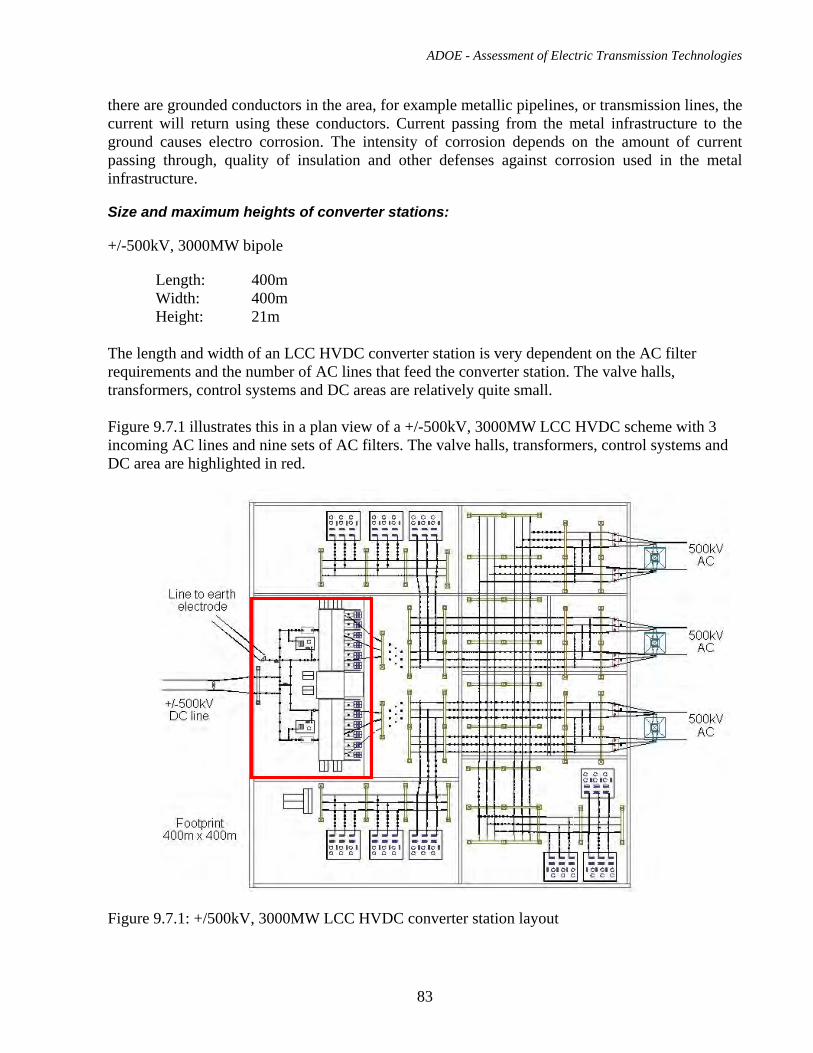
ADOE - Assessment of Electric Transmission Technologies
83
there are grounded conductors in the area, for example metallic pipelines, or transmission lines, the current will return using these conductors. Current passing from the metal infrastructure to the ground causes electro corrosion. The intensity of corrosion depends on the amount of current passing through, quality of insulation and other defenses against corrosion used in the metal infrastructure.
Size and maximum heights of converter stations:
+/-500kV, 3000MW bipole
Length: 400m Width: 400m Height: 21m
The length and width of an LCC HVDC converter station is very dependent on the AC filter requirements and the number of AC lines that feed the converter station. The valve halls, transformers, control systems and DC areas are relatively quite small. Figure 9.7.1 illustrates this in a plan view of a +/-500kV, 3000MW LCC HVDC scheme with 3 incoming AC lines and nine sets of AC filters. The valve halls, transformers, control systems and DC area are highlighted in red.
Figure 9.7.1: +/500kV, 3000MW LCC HVDC converter station layout
ADOE - Assessment of Electric Transmission Technologies
84
A +/-600kV, up to 4000MW converter station would have similar dimensions to Figure 9.7.1, except the height would be 22m.
The footprint of the area for the AC filters and the AC switchgear can be reduced by using Gas Insulated Switchgear rather than the more traditional Air Insulated Switchgear.
9.8. Operation and Maintenance
Operation Staffing:
The number of staff required will depend on how the scheme is to be operated, options are:
• The converter stations are completely unmanned, with the scheme being controlled from a regional dispatch centre.
This would require that a minimum of one of the persons on duty at all times in the regional dispatch centre is a fully trained HVDC scheme operator. Assuming 2 x 12 hours shifts, plus cover for absences, etc, 6 operators would normally be fully trained.
• Just one converter station is manned, with the other controlled from the manned station.
This would require that a minimum of two fully trained HVDC scheme operators are on duty at all times in the manned converter station. Assuming 2 x 12 hours shifts, plus cover for absences, etc, a minimum of 12 operators are fully trained.
• Both converter stations are manned.
This would require that a minimum of two fully trained HVDC scheme operators are on duty at all times in both of the converter stations. Assuming 2 x 12 hours shifts, plus cover for absences, etc, a minimum of 16 operators are fully trained.
Training:
As part of the commissioning stage of a project, the converter stations supplier would fully train the operators (and maintenance staff, if needed) in the use of the HVDC system. This includes how to make adjustment to setpoint parameters, how to interpret all of the annunciation panels - warnings, etc. The training does not enable the operators to determine set point values etc, this must come from the client’s operational dispatch managers.
It is recommended that refresher training courses are planned for both operators and maintenance staff at the appropriate times, depending on staff turnover. These are normally arranged in the converter stations themselves, but could occur at the supplier’s premises.
Maintenance:
Each pole (in the monopole case there is only one, and in the bipole case there are two) should be maintained at intervals of two years. Some work can be carried out without interrupting operation of the pole, for example, on redundant items, such as control systems and by isolating AC or DC
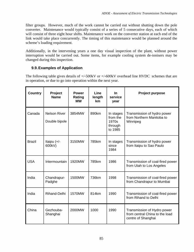
ADOE - Assessment of Electric Transmission Technologies
85
filter groups. However, much of the work cannot be carried out without shutting down the pole converter. Maintenance would typically consist of a series of 5 consecutive days, each of which will consist of three eight hour shifts. Maintenance work on the converter station at each end of the link would take place concurrently. The timing of this maintenance would be planned around the scheme’s loading requirement.
Additionally, in the intervening years a one day visual inspection of the plant, without power interruption would be carried out. Some items, for example cooling system de-ionisers may be changed during this inspection.
9.9. Examples of Application
The following table gives details of +/-500kV or +/-600kV overhead line HVDC schemes that are in operation, or due to go into operation within the next year.
Country Project Name
Power Rating
MW
Line length
km
In service
year
Project purpose
Canada Nelson River
Double bipole
3854MW 890km In stages from the 1970s through to 1985
Transmission of hydro power from Northern Manitoba to Winnipeg
Brazil Itaipu (+/-600kV)
3150MW 785km In stages since 1984
Transmission of hydro power from Itaipu to Sao Paulo
USA Intermountain 1920MW 785km 1986 Transmission of coal-fired power from Utah to Los Angeles
India Chandrapur-Padghe
1500MW 736km 1998 Transmission of coal-fired power from Chandrapur to Mumbai
India Rihand-Delhi 1570MW 814km 1990 Transmission of coal-fired power from Rihand to Delhi
China Gezhouba-Shanghai
2000MW 1000 1990 Transmission of Hydro power from central China to the load centre of Shanghai
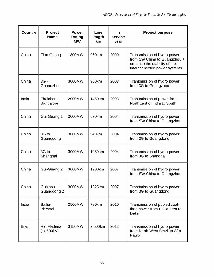
ADOE - Assessment of Electric Transmission Technologies
86
Country Project Name
Power Rating
MW
Line length
km
In service
year
Project purpose
China Tian-Guang 1800MW, 960km 2000 Transmission of hydro power from SW China to Guangzhou + enhance the stability of the interconnected power systems
China 3G - Guanqzhou,
3000MW 900km 2003 Transmission of hydro power from 3G to Guangzhou
India Thalcher - Bangalore
2000MW 1450km 2003 Transmission of power from NorthEast of India to South
China Gui-Guang 1 3000MW 980km 2004 Transmission of hydro power from SW China to Guangzhou
China 3G to Guangdong
3000MW 940km 2004 Transmission of hydro power from 3G to Guangdong
China 3G to Shanghai
3000MW 1059km 2004 Transmission of hydro power from 3G to Shanghai
China Gui-Guang 2 3000MW 1200km 2007 Transmission of hydro power from SW China to Guangzhou
China Guizhou-Guangdong 2
3000MW 1225km 2007 Transmission of hydro power from 3G to Guangdong
India Ballia-Bhiwadi
2500MW 780km 2010 Transmission of pooled coal-fired power from Ballia area to Delhi
Brazil Rio Madeira (+/-600kV)
3150MW 2,500km 2012 Transmission of hydro power from North West Brazil to São Paulo
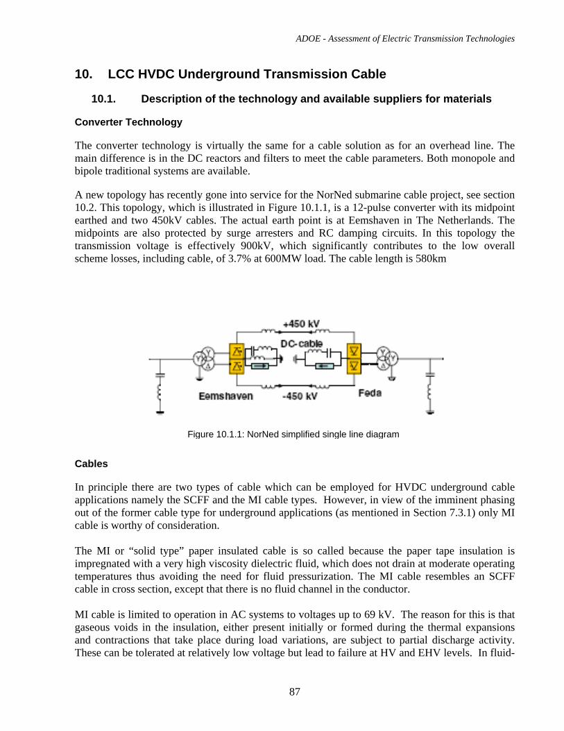
ADOE - Assessment of Electric Transmission Technologies
87
10. LCC HVDC Underground Transmission Cable
10.1. Description of the technology and available suppliers for materials
Converter Technology
The converter technology is virtually the same for a cable solution as for an overhead line. The main difference is in the DC reactors and filters to meet the cable parameters. Both monopole and bipole traditional systems are available.
A new topology has recently gone into service for the NorNed submarine cable project, see section 10.2. This topology, which is illustrated in Figure 10.1.1, is a 12-pulse converter with its midpoint earthed and two 450kV cables. The actual earth point is at Eemshaven in The Netherlands. The midpoints are also protected by surge arresters and RC damping circuits. In this topology the transmission voltage is effectively 900kV, which significantly contributes to the low overall scheme losses, including cable, of 3.7% at 600MW load. The cable length is 580km
Cables
In principle there are two types of cable which can be employed for HVDC underground cable applications namely the SCFF and the MI cable types. However, in view of the imminent phasing out of the former cable type for underground applications (as mentioned in Section 7.3.1) only MI cable is worthy of consideration. The MI or “solid type” paper insulated cable is so called because the paper tape insulation is impregnated with a very high viscosity dielectric fluid, which does not drain at moderate operating temperatures thus avoiding the need for fluid pressurization. The MI cable resembles an SCFF cable in cross section, except that there is no fluid channel in the conductor. MI cable is limited to operation in AC systems to voltages up to 69 kV. The reason for this is that gaseous voids in the insulation, either present initially or formed during the thermal expansions and contractions that take place during load variations, are subject to partial discharge activity. These can be tolerated at relatively low voltage but lead to failure at HV and EHV levels. In fluid-
Figure 10.1.1: NorNed simplified single line diagram
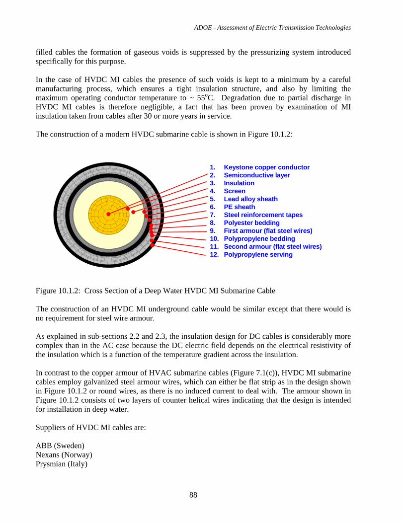
ADOE - Assessment of Electric Transmission Technologies
88
filled cables the formation of gaseous voids is suppressed by the pressurizing system introduced specifically for this purpose. In the case of HVDC MI cables the presence of such voids is kept to a minimum by a careful manufacturing process, which ensures a tight insulation structure, and also by limiting the maximum operating conductor temperature to ~ 55oC. Degradation due to partial discharge in HVDC MI cables is therefore negligible, a fact that has been proven by examination of MI insulation taken from cables after 30 or more years in service. The construction of a modern HVDC submarine cable is shown in Figure 10.1.2: Figure 10.1.2: Cross Section of a Deep Water HVDC MI Submarine Cable The construction of an HVDC MI underground cable would be similar except that there would is no requirement for steel wire armour. As explained in sub-sections 2.2 and 2.3, the insulation design for DC cables is considerably more complex than in the AC case because the DC electric field depends on the electrical resistivity of the insulation which is a function of the temperature gradient across the insulation. In contrast to the copper armour of HVAC submarine cables (Figure 7.1(c)), HVDC MI submarine cables employ galvanized steel armour wires, which can either be flat strip as in the design shown in Figure 10.1.2 or round wires, as there is no induced current to deal with. The armour shown in Figure 10.1.2 consists of two layers of counter helical wires indicating that the design is intended for installation in deep water. Suppliers of HVDC MI cables are: ABB (Sweden) Nexans (Norway) Prysmian (Italy)
1. Keystone copper conductor 2. Semiconductive layer 3. Insulation 4. Screen 5. Lead alloy sheath 6. PE sheath 7. Steel reinforcement tapes 8. Polyester bedding 9. First armour (flat steel wires) 10. Polypropylene bedding 11. Second armour (flat steel wires) 12. Polypropylene serving
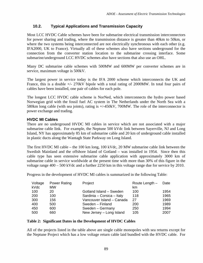
ADOE - Assessment of Electric Transmission Technologies
89
10.2. Typical Applications and Transmission Capacity
Most LCC HVDC Cable schemes have been for submarine electrical transmission interconnectors for power sharing and trading, where the transmission distance is greater than 40km to 50km, or where the two systems being interconnected are not electrically synchronous with each other (e.g. IFA2000, UK to France). Virtually all of these schemes also have sections underground for the connection from the converter station location to the submarine crossing interface. Some submarine/underground LCC HVDC schemes also have sections that also use an OHL.
Many DC submarine cable schemes with 500MW and 600MW per converter schemes are in service, maximum voltage is 500kV.
The largest power in service today is the IFA 2000 scheme which interconnects the UK and France, this is a double +/- 270kV bipole with a total rating of 2000MW. In total four pairs of cables have been installed, one pair of cables for each pole.
The longest LCC HVDC cable scheme is NorNed, which interconnects the hydro power based Norwegian grid with the fossil fuel AC system in The Netherlands under the North Sea with a 580km long cable (with sea joints), rating is +/-450kV, 700MW. The role of the interconnector is power exchange and trading.
HVDC MI Cables There are no underground HVDC MI cables in service which are not associated with a major submarine cable link. For example, the Neptune 500 kVdc link between Sayerville, NJ and Long Island, NY has approximately 85 km of submarine cable and 20 km of underground cable installed in plastic ducts along the Wantagh State Parkway on Long Island. The first HVDC MI cable – the 100 km long, 100 kVdc, 20 MW submarine cable link between the Swedish Mainland and the offshore Island of Gotland – was installed in 1954. Since then this cable type has seen extensive submarine cable application with approximately 3000 km of submarine cable in service worldwide at the present time with more than 30% of this figure in the voltage range 400 – 500 kVdc and a further 2250 km in this voltage range due for service by 2010. Progress in the development of HVDC MI cables is summarized in the following Table:
Voltage kVdc
Power Rating MW
Project Route Length – km
Date
100 20 Gotland Island – Sweden 100 1954 200 100 Sardinia – Corsica – Italy 118 1965 300 156 Vancouver Island – Canada 27 1969 400 500 Sweden – Finland 200 1989 450 600 Sweden – Germany 250 1994 500 660 New Jersey – Long Island 105 2007
Table 2: Significant Dates in the Development of HVDC Cables All of the projects listed in the table above are single cable monopoles with sea returns except for the Neptune Project which has a low voltage return cable laid bundled with the HVDC cable. For
ADOE - Assessment of Electric Transmission Technologies
90
land applications a 500 kVdc 2-cable bipole laid in a touching cable configuration would have a transmission capacity in the order of 1300 MW. In theory there is no length limitation for HVDC MI cables on land but in practice the transmission distance may be limited to 20 km because of the number of splices. ABB has already stated that distances in the order of 100 km for land cable would not be considered to be practical.
10.3. Performance in Service, Reliability, Safety and Efficiency
For the converter stations this is identical to the LCC HVDC OHL, see section 9.3
There are no significant sections of MI cable on land, except for the 20 km of land cable for the Neptune project – and that cable has had trouble-free service for the two years since it was installed. According to the recent CIGRE survey (see also section 7.3.1) there are no known failures of HVDC MI submarine cables due to intrinsic quality problems. The overall failure rate due mainly to external origins such as fishing and vessel anchoring activities is quoted as ~ 0.1 failures per year per 100 km.
10.4. EPC Cost for +/-500kV HVDC Underground Transmission Cable Recent budgetary unit costs for the supply ex-works Europe of a 500 kVdc MI cable with a 2000 mm2 copper Conci conductor are as follows: Cable cost: 500,000 Euro / km single cable $810,000 CAD / km single cable Splice cost: 40, 000 Euro/ pc $64,800 CAD / pc Termination Cost: 200,000 Euro/ pc $324,000 CAD / pc Exchange rate as of July 4, 2009: Euro 1.0 = $ 1.62 CAD For the purpose of the cost estimate it was anticipated that two bipole cable lines would be installed to match the 2000 MW converter. One line would be capable of carrying approximately 1300 MW. Each line would carry 1000 MW during normal operation to give the required 2000 MW total power transfer. With one line out of service for 60 days, the remaining line would be able to carry 1300 MW. Charging current is negligible. The contractor’s cost for engineering, management, civil and cable installation works is estimated be: $1,913,450.CAD/km. Figure 10.6(a) of section 10.6 shows the potential cable trench cross-section. Losses have been estimated at 40 W/m per 2-cable bipole transmitting 1300 MW.
ADOE - Assessment of Electric Transmission Technologies
91
As noted in the body of the report, MI cables are considered limited to 20 km or so on land because of the need for time-consuming hand-taped splices.
10.5. EPC Cost for +/-500kV LCC HVDC Converters
Full turnkey EPC cost for the converter stations for a typical 750MW LCC HVDC cable scheme as a 500kV monopole is ~$125 million CAD at current exchange rates.
Full turnkey EPC cost for the converter stations for a typical 1000MW LCC HVDC cable scheme as a +/-500kV bipole is ~$180 million CAD at current exchange rates.
Full turnkey EPC cost for the converter stations for a typical 2000MW LCC HVDC cable scheme as a +/-500kV bipole is ~$260 million CAD at current exchange rates. Note that this rating may require two cables to be connected in parallel per pole.
Total converter station losses for the scheme is 1.4% of scheme nominal rating.
10.6. Right of Way Requirements A potential trench cross-section is shown in Figure 10.6(a). The go and return cables are touching, as done for the Neptune Project. Assuming the utility would require a 5 m clear distance each side of the cable trench, a permanent right-of-way width of approximately 13 m would be needed. The construction ROW would be 5 to10 m wider to allow room for materials and construction equipment. The cables would be placed in a duct unless they are in areas that can be easily accessed for repairs.
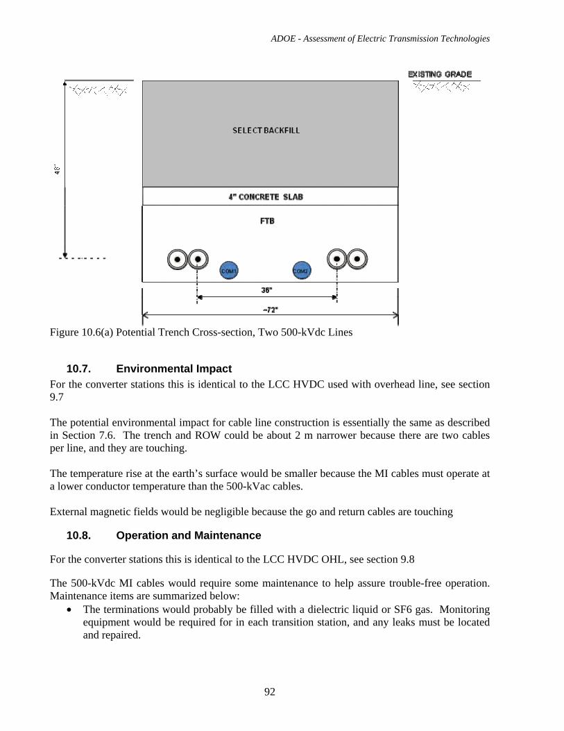
ADOE - Assessment of Electric Transmission Technologies
92
Figure 10.6(a) Potential Trench Cross-section, Two 500-kVdc Lines
10.7. Environmental Impact For the converter stations this is identical to the LCC HVDC used with overhead line, see section 9.7 The potential environmental impact for cable line construction is essentially the same as described in Section 7.6. The trench and ROW could be about 2 m narrower because there are two cables per line, and they are touching. The temperature rise at the earth’s surface would be smaller because the MI cables must operate at a lower conductor temperature than the 500-kVac cables. External magnetic fields would be negligible because the go and return cables are touching
10.8. Operation and Maintenance
For the converter stations this is identical to the LCC HVDC OHL, see section 9.8
The 500-kVdc MI cables would require some maintenance to help assure trouble-free operation. Maintenance items are summarized below:
• The terminations would probably be filled with a dielectric liquid or SF6 gas. Monitoring equipment would be required for in each transition station, and any leaks must be located and repaired.
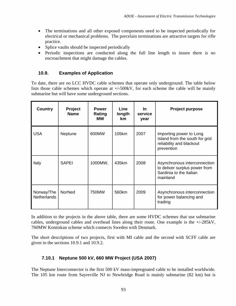
ADOE - Assessment of Electric Transmission Technologies
93
• The terminations and all other exposed components need to be inspected periodically for electrical or mechanical problems. The porcelain terminations are attractive targets for rifle practice.
• Splice vaults should be inspected periodically • Periodic inspections are conducted along the full line length to insure there is no
encroachment that might damage the cables.
10.9. Examples of Application
To date, there are no LCC HVDC cable schemes that operate only underground. The table below lists those cable schemes which operate at +/-500kV, for each scheme the cable will be mainly submarine but will have some underground sections.
Country Project Name
Power Rating
MW
Line length
km
In service
year
Project purpose
USA Neptune 600MW 105km 2007 Importing power to Long Island from the south for grid reliability and blackout prevention
Italy SAPEI 1000MW, 435km 2008 Asynchronous interconnection to deliver surplus power from Sardinia to the Italian mainland
Norway/The Netherlands
NorNed 750MW 560km 2009 Asynchronous interconnection for power balancing and trading
In addition to the projects in the above table, there are some HVDC schemes that use submarine cables, underground cables and overhead lines along their route. One example is the +/-285kV, 760MW Kontiskan scheme which connects Sweden with Denmark.
The short descriptions of two projects, first with MI cable and the second with SCFF cable are given in the sections 10.9.1 and 10.9.2.
7.10.1 Neptune 500 kV, 660 MW Project (USA 2007) The Neptune Interconnector is the first 500 kV mass-impregnated cable to be installed worldwide. The 105 km route from Sayreville NJ to Newbridge Road is mainly submarine (82 km) but is
ADOE - Assessment of Electric Transmission Technologies
94
important in the present context because of the ~20 km of 500 kV MI underground cable which runs along the Wantagh Parkway from the cable landing point at Jones Beach on Long Island to the Newbridge Road converter station. This cable, which is the longest underground HVDC MI cable ever installed, was laid in lengths of at least 500 m in polyethylene conduits which were pre-installed by “cut and cover” trenching techniques or in places where trenching was not feasible by horizontal directional drilling (HDD) techniques. The Neptune Interconnection has been in service since July 2007. Supplier: Prysmian Power Link
10.9.2 450 KV DC Crossing of the St. Lawrence River (Canada 1992) Due to difficult conditions in the River (high currents, rocky outcrops) and a ruling by the Canadian Government Transport department that deep burial in the river bed would be necessary Hydro Quebec decided on a tunnel installation. In 1992 Hydro Quebec selected SCFF cable technology in preference to MI technology due to the satisfactory testing experience in Japan and in Europe at that time. The six cables were manufactured in 5.1 km lengths (the distance between terminal points at the tunnel ends) and loaded into cable trays weighing 250 tons each which were transported along the final 2 km of route to the tunnel on flat-bed trailers. This is the only HVDC cable not associated with a submarine cable link presently in existence. Supplier: J-Power (Hitachi)
11. VSC HVDC Overhead Transmission Line
11.1. Description of the technology and available suppliers for materials The acronym VSC means Voltage Source Converter. A VSC HVDC scheme has the same objectives as an LCC HVDC scheme, i.e. AC current is rectified to DC current at one converter station and then transmitted to the remote station where the DC current is inverted to form AC current.
Although VSC techniques have been in use in industrial and transport applications for many years, it is a relatively new solution for HVDC - made possible by the recent availability of high voltage, high power transistors. To date there are only 10 schemes in operation, with 4 others in different stages of construction.
As mentioned above, the VSC uses transistors, rather than thyristors, in its converter structure, this means that the converter can be self-commutating and does not require any synchronization to the
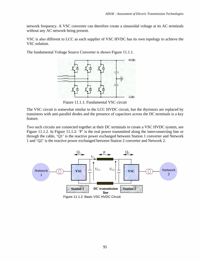
ADOE - Assessment of Electric Transmission Technologies
95
network frequency. A VSC converter can therefore create a sinusoidal voltage at its AC terminals without any AC network being present.
VSC is also different to LCC as each supplier of VSC HVDC has its own topology to achieve the VSC solution.
The fundamental Voltage Source Converter is shown Figure 11.1.1.
The VSC circuit is somewhat similar to the LCC HVDC circuit, but the thyristors are replaced by transistors with anti-parallel diodes and the presence of capacitors across the DC terminals is a key feature.
Two such circuits are connected together at their DC terminals to create a VSC HVDC system, see Figure 11.1.2. In Figure 11.1.2: ‘P’ is the real power transmitted along the interconnecting line or through the cable, ‘Q1’ is the reactive power exchanged between Station 1 converter and Network 1 and ‘Q2’ is the reactive power exchanged between Station 2 converter and Network 2.
Figure 11.1.1: Fundamental VSC circuit
DC transmissionline
Q1 Q2P
VSC VSC
Station 1 Station 2
UC1 UC2
IC1
Network1
Network2
Figure 11.1.2: Basic VSC HVDC Circuit
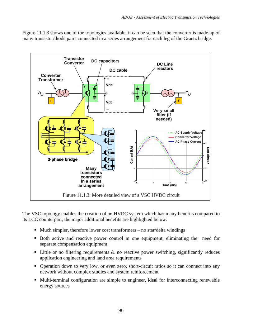
ADOE - Assessment of Electric Transmission Technologies
96
Figure 11.1.3 shows one of the topologies available, it can be seen that the converter is made up of many transistor/diode pairs connected in a series arrangement for each leg of the Graetz bridge.
The VSC topology enables the creation of an HVDC system which has many benefits compared to its LCC counterpart, the major additional benefits are highlighted below:
Much simpler, therefore lower cost transformers – no star/delta windings
Both active and reactive power control in one equipment, eliminating the need for separate compensation equipment
Little or no filtering requirements & no reactive power switching, significantly reduces application engineering and land area requirements
Operation down to very low, or even zero, short-circuit ratios so it can connect into any network without complex studies and system reinforcement
Multi-terminal configuration are simple to engineer, ideal for interconnecting renewable energy sources
Converter Transformer
DC cable
Many transistors connected in a series
arrangement
DC Line reactors
+Vdc
_Vdc
Transistor Converter
3-phase bridge3-phase bridge
DC capacitors
FF F
Very small filter (if needed)
Cur
rent
(kA
)
Volta
ge (k
V)
Time (ms)
AC Supply VoltageConverter VoltageAC Phase Current
Cur
rent
(kA
)
Volta
ge (k
V)
Time (ms)
AC Supply VoltageConverter VoltageAC Phase Current
Figure 11.1.3: More detailed view of a VSC HVDC circuit
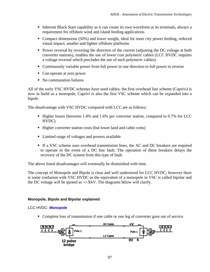
ADOE - Assessment of Electric Transmission Technologies
97
Inherent Black Start capability as it can create its own waveform at its terminals, always a requirement for offshore wind and island feeding applications
Compact dimensions (50%) and lower weight, ideal for inner city power feeding, reduced visual impact, smaller and lighter offshore platforms
Power reversal by reversing the direction of the current (adjusting the DC voltage at both converter stations), enables the use of lower cost polymeric cables (LCC HVDC requires a voltage reversal which precludes the use of such polymeric cables).
Continuously variable power from full power in one direction to full power in reverse
Can operate at zero power
No commutation failures
All of the early VSC HVDC schemes have used cables; the first overhead line scheme (Caprivi) is now in build as a monopole, Caprivi is also the first VSC scheme which can be expanded into a bipole.
The disadvantage with VSC HVDC compared with LCC are as follows:
Higher losses (between 1.4% and 1.6% per converter station, compared to 0.7% for LCC HVDC)
Higher converter station costs (but lower land and cable costs)
Limited range of voltages and powers available
If a VSC scheme uses overhead transmission lines, the AC and DC breakers are required to operate in the event of a DC line fault. The operation of these breakers delays the recovery of the DC system from this type of fault.
The above listed disadvantages will eventually be diminished with time.
The concept of Monopole and Bipole is clear and well understood for LCC HVDC, however there is some confusion with VSC HVDC as the equivalent of a monopole in VSC is called bipolar and the DC voltage will be quoted as +/-XkV. The diagrams below will clarify.
Monopole, Bipole and Bipolar explained
LCC HVDC: Monopole
Complete loss of transmission if one cable or one leg of converter goes out of service
FF F FFF F FPole 1 Pole 1
HV Cable
LV Cable
+V
0V12 pulse bridge
FF F FFF F FPole 1 Pole 1
HV Cable
LV Cable
+V
0V12 pulse bridge
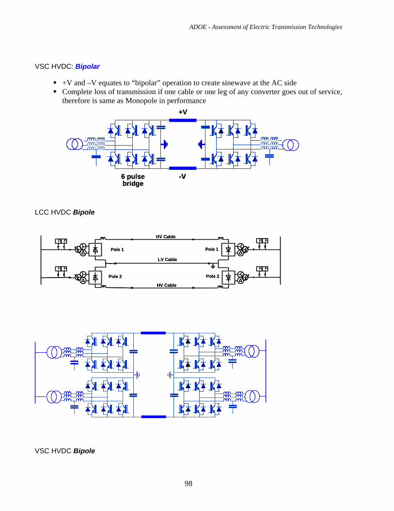
ADOE - Assessment of Electric Transmission Technologies
98
VSC HVDC: Bipolar
+V and –V equates to “bipolar” operation to create sinewave at the AC side Complete loss of transmission if one cable or one leg of any converter goes out of service,
therefore is same as Monopole in performance
LCC HVDC Bipole
VSC HVDC Bipole
+V
-V6 pulse bridge
+V
-V-V6 pulse bridge
FF F F
FF F F
Pole 1 Pole 1
Pole 2 Pole 2
HV Cable
LV Cable
HV Cable
FF F F
FF F F
Pole 1 Pole 1
Pole 2 Pole 2
HV Cable
LV Cable
HV Cable
ADOE - Assessment of Electric Transmission Technologies
99
Available Suppliers
As for LCC HVDC, due to the massive research and development programs required to support such an activity, as well as the breadth of experience beyond the power electronics aspects necessary to complete a VSC HVDC scheme, there are very few suppliers of VSC HVDC systems.
These suppliers are:
• ABB - based in Ludvika, Sweden – installed its first VSC demonstrator scheme in 1997, since then has installed 8 further schemes and has 3 schemes in various stages of implementation.
• Siemens – based in Erlangen, Germany – a 20MW back-to-back demonstrator has been installed at Siemens’ facility in Erlangen and its first scheme is currently under construction, it is expected to be in service during 2010.
• AREVA – based in Stafford, UK – is finalizing its R&D program, its 25MW back-to-back demonstrator is planned to be installed early 2010 and commercial projects will be accepted from Q2/2010.
11.2. Typical Applications and Transmission Capacity
Typical applications for VSC HVDC overhead line schemes are similar to those for LCC HVDC as described in section 9.2, i.e.:
Efficient power transfer, point-to-point over long distances using overhead lines
Interconnecting asynchronous regions together
However, the VSC system does allow multi-terminal schemes with an unlimited number of nodes to be easily built. No examples of this are yet available anywhere in the world. However, discussions are occurring in Europe concerning an HVDC overlay on top of the AC network to strengthen the European systems and also to integrate potential concentrated solar power from the deserts in southern Europe and the Sahara.
The VSC HVDC solution does have the capability to provide a solution for overhead lines that interconnect very weak systems, without any system reinforcement being needed. It also can be used to provide power to an ‘islanded’ region that does not have any generation of its own, without the deployment of diesel generators and rotating synchronous compensators. It can also be applied where the demand for land is critical as it requires only 50% of the land area compared to its LCC equivalent.
Today there is no VSC HVDC overhead line schemes in service, there is just one in build, the Caprivi project and this is expected to go into service in 2010. Rating is: +350kV, 300MW as a monopole.
In years to come, the VSC HVDC technology could potentially be able to reach:
ADOE - Assessment of Electric Transmission Technologies
100
Voltage: up to 500kV or even 600kV; Power: up to 2000MW or even 2500MW
No timelines for such solutions are commercially available, the progress will depend somewhat on the availability of higher voltage/power transistor devices.
11.3. Performance in Service, Reliability, Safety and Efficiency
Overload:
Current VSC HVDC technologies do not offer a significant inherent overload capability. Typically there will be a 5% overload rating applicable at low ambient temperatures
Reactive Power exchange
With VSC HVDC both the active and reactive power can be independently controlled and, depending on the application, up to 1.0 pu reactive power can be generated or consumed.
AC side harmonics:
THD (rms value of total harmonic distortion) up to 40th harmonic: <3.0%
Minimum Power Flow:
The minimum power flow that can be achieved for a VSC HVDC scheme is zero.
Power reversal:
A VSC HVDC scheme can transmit active power in any direction and also reverse it without any control mode changes. Full power reversal could occur in milliseconds, but in practice the power reversal time will be limited by the network. Reactive power continues to operate independently during an active power reversal to maintain the required level of reactive power exchange.
Mode switching from Bipole to Monopole operation:
The switch from bipole to monopole operation is achieved purely by the operation of the transistor valves, the transfer time is approximately 40ms.
Start-up and Shut-down:
VSC HVDC systems can be automated to the extent that they can normally operate totally unmanned. Therefore, the start-up and shut-down process does not require any on-site staff intervention, however, there must be a push-button initiation from a remote dispatch centre or similar.
Interferences:
The AC and DC filters and good grounding will suppress emissions at telephone frequencies. Power Line Carrier (PLC) interference is prevented by the PLC filter
ADOE - Assessment of Electric Transmission Technologies
101
Radio interference is prevented by good grounding, shielding and radio frequency filters
Reliability
No reliability figures have yet been issued as the systems have not been in service for long periods yet and until recently there has only been one supplier (ABB).
ABB’s own figures are:
Forced outage rate 1 - 2 outages/year Forced unavailability 0.3 - 0.5% Unforced (scheduled) unavailability < 0.4% Availability >99.0% This compares very well with LCC, but is not yet proven.
Safety
For the converter stations this is identical to the LCC HVDC OHL, see section 9.3
Efficiency
Power losses of converter stations are currently between 1.4% and 1.6% per converter, leading to 2.8% to 3.2% for a complete scheme.
These loss figures will reduce with time as new developments come on stream. The target will be to reach parity with LCC, however there is no commitment yet from any supplier to achieve such parity.
11.4. EPC Cost for +/- 200 kV HVDC Overhead Transmission Line Engineering, procurement and construction (EPC) cost has been estimated for a case of +/- 200kV direct current bipolar overhead line. It has been assumed that latticed steel self-supporting towers carry two bundled conductors – one for each HVDC pole. Each bundled conductor consists of two sub-conductors: ACSR code name ‘Falcon’. One shield wire is installed on top of tower. The general outline for a straight line ‘tangent” tower is shown in Fig. 16.3(a). Power capacity of the line is suitable for transmitting 600MW which is the rating of the converter assumed in the cost study case. The transmission losses as the percentage of the rated power will be approximately 1.3% for 100km line, 4% for 300km line and 8% for 600 km line. The estimated cost for +/-200kV HVDC overhead transmission line is: $592,000 CAD/km The +/-200kV voltage level for VSC HVDC system has been adopted as the cost study case because at the moment it can be considered as proven technology and the converter prices can be
ADOE - Assessment of Electric Transmission Technologies
102
obtained for that scheme. Caprivi Link project, the 300MW. 350kV HVDC VSC monopole (expandable to 600MW , +/-350 kV bipole), is presently under construction.
11.5. EPC Cost for +/- 200 kV VSC HVDC Converters
Full turnkey EPC cost for the converter stations for a +/-200kV, 400MW VSC as a bipolar overhead line scheme is estimated to be ~$180 million CAD at current exchange rates. This scheme requires two fully insulated overhead wires.
Full turnkey EPC cost for the converter stations for a +/-200kV, 600MW VSC as a true bipole overhead line scheme is estimated to be ~$250 million CAD at current exchange rates. This scheme requires two fully insulated overhead wires. This price is a pure estimate as such a scheme has not yet even been tendered.
11.6. Right of Way Requirements Using similar criteria as those described in section 6.7 the width of right-of –way for +/-200kV HVDC overhead transmission line is estimated to be 35 m approximately. This line can be considered as a “light” line and, if necessary, it can be designed to fit into a narrower right-of –way.
11.7. Environmental Impact The section 9.7 related to environmental impact of +/-500 kV HVDC overhead lines is applicable also for +/-200 kV HVDC lines.
For the converter stations this will be identical to LCC HVDC OHL, see section 9.8, except for the size and maximum heights of converter stations
Typical dimensions for +/-200kV VSC HVDC Converter stations at two different ratings are:
700MW Length: 90m Width: 65m Height: 16m
350MW Length: 80m Width: 32m Height: 13m
ADOE - Assessment of Electric Transmission Technologies
103
Indicative dimensions for a +/-300kV, 1000MW VSC Converter station are: Length: 110m Width: 75m Height: 24m
11.8. Operation and Maintenance
For the converter stations this will be identical to LCC HVDC OHL, see section 9.8
11.9. Examples of Application
Phase 1 of the first overhead line VSC HVDC scheme is currently in build (Caprivi), it is being built as a true monopole. In a possible phase 2, which is not yet even out to tender, another monopole may be added to create a bipole, if/when this happens the scheme will become the first VSC HVDC bipole.
All other VSC HVDC schemes are ‘bipolar’, this is effectively a monopole in its capabilities, see section 11.1.
Details of the Caprivi scheme are as follows:
Country: Namibia
Voltage: 350kV
Power: 300MW
Line length: 970km
Application:
Interconnector transmission link between the north-eastern Caprivi region and the power network in central Namibia. This link will also interconnect the electricity networks of Namibia, Zambia, Zimbabwe, the Democratic Republic of Congo, Mozambique and South Africa to create route for power import and exports. Additionally to electrically connect the northeastern part of the country to central Namibia as the two networks are very weak and the VSC HVDC scheme will help stabilize them.
12. VSC HVDC Underground Transmission Cable
12.1. Description of the technology and available suppliers for materials
The converter technology is virtually the same for an underground cable solution as for an overhead line. The main difference is in the DC reactors and filters to meet the cable parameters.
ADOE - Assessment of Electric Transmission Technologies
104
Both MI and XLPE cables can be considered for use in VSC HVDC transmission systems. The technology of the former has already been outlined in Section 10.1 therefore only XLPE cable technology is addressed in this Section. The use of HVDC XLPE cables was delayed due to complications with insulation design caused by space charge accumulation. This causes a significant reduction in the electric strength at the operating temperature, particularly when the polarity is reversed to reverse the direction of power flow. Recent progress in the development of modified XLPE using special “functional groups” has been successful in solving the space charge problem and as a result VSC technology with modified-XLPE cable links is beginning to be employed at voltages up to 200 kVdc. Modified-XLPE HVdc technology has also been used for underground cable applications, which include the 150 kVdc, 180 km long Murraylink project in Australia which was installed in 2000. The fact that (in some scenarios) cables, rather than overhead lines, must be used the entire distance between converters, to avoid possible damage to converters caused by overhead line pole-to-pole faults, may prove to be a disadvantage. This will be no more the case, the Caprivi Link, +350kV project in Namibia, will be the first HVDC VSC scheme that uses overhead line. Suppliers: ABB Prysmian Nexans (due to release their cable in 2010) All of the above suppliers are type-test qualified up to and including the 300 kV voltage level although 150 kVdc is the maximum voltage currently in service.
12.2. Typical Applications and Transmission Capacity VSC systems as described above have been used for underground and submarine crossing applications at voltages up to and including 150 kVdc for one or more of the advantages listed above in Section 12.1. Typical transmission capacities for 150 kV projects lie in the range of 330 – 350 MW. At 200 kV the expected transmission capacity would be at least 400 MW.
. Other applications are:
Interconnecting asynchronous regions together.
Multi-terminal schemes with an unlimited number of nodes, see section 15.1. No examples of this are yet available anywhere in the world.
To interconnect very weak systems, without any system reinforcement being needed.
ADOE - Assessment of Electric Transmission Technologies
105
It also can be used to provide power to an ‘islanded’ region that does not have any generation of its own, without the deployment of diesel generators and synchronous compensators. It can also be applied where the demand for land is critical as it requires only 50% of the land area required by the LCC equivalent.
Linking up with VSC HVDC overhead line systems
Capacities of underground cable VSC HVDC schemes in service today are:
Voltages: from 80kV to 150kV; Powers: from 180MW to 200MW
Converter ratings for submarine VSC HVDC cable schemes in service today are:
Voltages: from 60kV to 150kV; Powers: from 50MW to 350MW
Converter ratings for submarine VSC HVDC cable schemes on order today, with expected in-service dates from 2010 to 2012, are:
Voltages: from 150kV to 300kV; Powers: from 78MW to 500MW
There are not any VSC HVDC fully underground schemes on order today.
A future application of VSC HVDC is as taps fed by an LCC HVDC scheme, see section 15.2
12.3. Performance in Service, Reliability, Safety and Efficiency
For the converter stations this is identical to the VSC HVDC OHL, see section 11.3
The technology is relatively new at HV levels so little information is available. It is known that on Murraylink several forced outages have happened. The most serious outage was due to HVDC cable fault which most likely occurred due to localized damage during construction. However, no further significant problems have been reported.
12.4. EPC Cost for +/-200kV HVDC Underground Transmission Cable There are no underground cables in service at this voltage level so very little information is available. The following budgetary cost for supply of material has been obtained for a ± 200 kVdc, 400 MW cable project with a route length of 20 km: Cable Cost: 4.5 million Euros $7.29 million CAD Splice Cost:: 5000 Euros / pc $8,100 CAD Termination Cost: 14,000 Euros / pc $22,680 CAD Cable Losses: 1.0 MW (for 20 km route) Exchange rate as of July 4, 2009: Euro 1.0 = $ Can 1.62
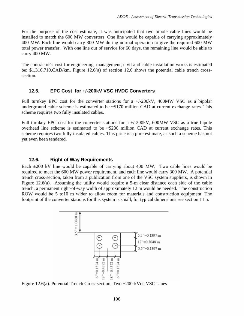
ADOE - Assessment of Electric Transmission Technologies
106
For the purpose of the cost estimate, it was anticipated that two bipole cable lines would be installed to match the 600 MW converters. One line would be capable of carrying approximately 400 MW. Each line would carry 300 MW during normal operation to give the required 600 MW total power transfer. With one line out of service for 60 days, the remaining line would be able to carry 400 MW. The contractor’s cost for engineering, management, civil and cable installation works is estimated be: $1,316,710.CAD/km. Figure 12.6(a) of section 12.6 shows the potential cable trench cross-section.
12.5. EPC Cost for +/-200kV VSC HVDC Converters
Full turnkey EPC cost for the converter stations for a +/-200kV, 400MW VSC as a bipolar underground cable scheme is estimated to be ~$170 million CAD at current exchange rates. This scheme requires two fully insulated cables.
Full turnkey EPC cost for the converter stations for a +/-200kV, 600MW VSC as a true bipole overhead line scheme is estimated to be ~$230 million CAD at current exchange rates. This scheme requires two fully insulated cables. This price is a pure estimate, as such a scheme has not yet even been tendered.
12.6. Right of Way Requirements Each ±200 kV line would be capable of carrying about 400 MW. Two cable lines would be required to meet the 600 MW power requirement, and each line would carry 300 MW. A potential trench cross-section, taken from a publication from one of the VSC system suppliers, is shown in Figure 12.6(a). Assuming the utility would require a 5-m clear distance each side of the cable trench, a permanent right-of-way width of approximately 12 m would be needed. The construction ROW would be 5 to10 m wider to allow room for materials and construction equipment. The footprint of the converter stations for this system is small, for typical dimensions see section 11.5.
Figure 12.6(a). Potential Trench Cross-section, Two ±200-kVdc VSC Lines
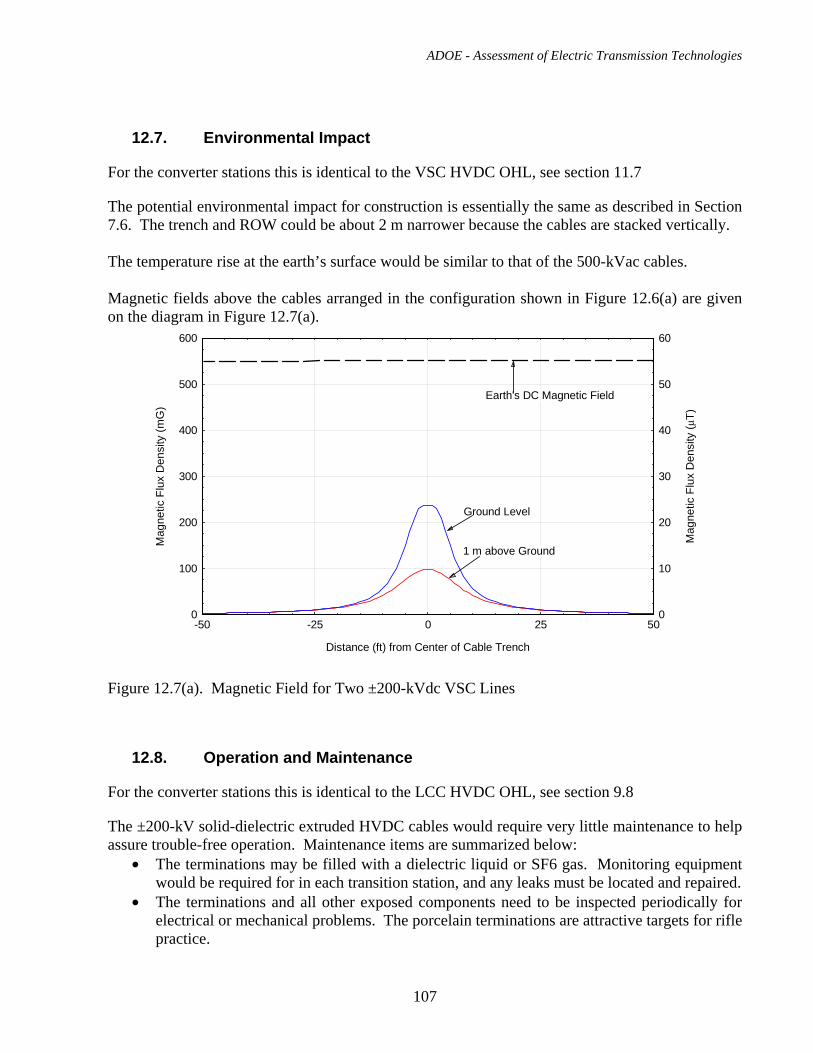
ADOE - Assessment of Electric Transmission Technologies
107
12.7. Environmental Impact
For the converter stations this is identical to the VSC HVDC OHL, see section 11.7
The potential environmental impact for construction is essentially the same as described in Section 7.6. The trench and ROW could be about 2 m narrower because the cables are stacked vertically. The temperature rise at the earth’s surface would be similar to that of the 500-kVac cables. Magnetic fields above the cables arranged in the configuration shown in Figure 12.6(a) are given on the diagram in Figure 12.7(a).
0
100
200
300
400
500
600
-50 -25 0 25 500
10
20
30
40
50
60
Earth's DC Magnetic Field
Ground Level
1 m above Ground
Distance (ft) from Center of Cable Trench
Mag
netic
Flu
x D
ensi
ty (m
G)
Mag
netic
Flu
x D
ensi
ty (μ
T)
Figure 12.7(a). Magnetic Field for Two ±200-kVdc VSC Lines
12.8. Operation and Maintenance
For the converter stations this is identical to the LCC HVDC OHL, see section 9.8
The ±200-kV solid-dielectric extruded HVDC cables would require very little maintenance to help assure trouble-free operation. Maintenance items are summarized below:
• The terminations may be filled with a dielectric liquid or SF6 gas. Monitoring equipment would be required for in each transition station, and any leaks must be located and repaired.
• The terminations and all other exposed components need to be inspected periodically for electrical or mechanical problems. The porcelain terminations are attractive targets for rifle practice.
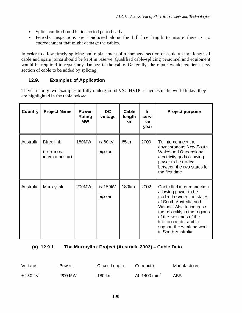
ADOE - Assessment of Electric Transmission Technologies
108
• Splice vaults should be inspected periodically • Periodic inspections are conducted along the full line length to insure there is no
encroachment that might damage the cables. In order to allow timely splicing and replacement of a damaged section of cable a spare length of cable and spare joints should be kept in reserve. Qualified cable-splicing personnel and equipment would be required to repair any damage to the cable. Generally, the repair would require a new section of cable to be added by splicing.
12.9. Examples of Application
There are only two examples of fully underground VSC HVDC schemes in the world today, they are highlighted in the table below:
Country Project Name Power Rating
MW
DC voltage
Cable length
km
In servi
ce year
Project purpose
Australia Directlink
(Terranora interconnector)
180MW +/-80kV
bipolar
65km 2000 To interconnect the asynchronous New South Wales and Queensland electricity grids allowing power to be traded between the two states for the first time
Australia Murraylink 200MW, +/-150kV
bipolar
180km 2002 Controlled interconnection allowing power to be traded between the states of South Australia and Victoria. Also to increase the reliability in the regions of the two ends of the interconnector and to support the weak network in South Australia
(a) 12.9.1 The Murraylink Project (Australia 2002) – Cable Data Voltage
Power
Circuit Length
Conductor
Manufacturer
± 150 kV 200 MW 180 km Al 1400 mm2 ABB
ADOE - Assessment of Electric Transmission Technologies
109
This project is not only the first underground cable application of VSC technology at an HV level but also holds the world record for the longest land cable installation ever. The 180 km route links substations at Berry and Red Cliffs in the Australian state of Victoria. Over 400 splices were required which means that the cables were lain in lengths in the order of 1,000 m.
(b) 12.9.2 The Transbay Project (California 2010) Voltage
Power
Circuit Length
Conductor
Manufacturer
± 200 kV 400 MW 88 km Cu 1300 mm2 Prysmian This project due to be completed in March 2010 will be the first ever VSC project to be placed into service at 200 kVdc. This is a submarine interconnection between substations at Pittsburg, CA and Potrero Substation in the city of San Francisco. The VSC converters will be supplied by Siemens.
13. UHVDC LCC Overhead Transmission Line
13.1. Description of the technology and available suppliers for materials
The ultra high voltage direct current (UHVDC) Overhead line technology is identical in its concept to the +/-500kV solutions as described in section 9.1 except that the voltage has been increased. Note, any voltage ≥ +/-600kV is classified as UHVDC.
The main differences will be highlighted in this section.
There are two slightly different drivers for UHVDC, one coming from China, the other from India.
China wants +/-800kV, 6400MW bipole LCC overhead line schemes with single converter stations at each end
India however, wants +/-800kV, 6000MW bipole LCC overhead line schemes with two +/-800kV, 3000MW converter stations at each end of the line, but with the two converter stations separated by say 100km away from each other and the 800kV. The two options are illustrated below:
ADOE - Assessment of Electric Transmission Technologies
110
China approach:
India approach:
Taking into account several factors, two different topologies have been developed for the two approaches. The important factors are:
Weight of transformers for manufacture and transport to the converter station site
Value of MW that the network can suddenly lose in the case of a trip
1600MW is normally OK
Size of thyristors
5” devices are readily available for ratings up to 4000MW and 6” devices are just becoming available for ratings to meet the needs of 6400MW
Need for bypass switches with 800kV DC rating
Such switches are now available
Additionally, new 800kV related bushings for transformers and the valve hall wall have been developed, along with 800kV class instrumentation.
+800kV
-800kV
6400MW bipole
6400MW bipole
6400MW
+800kV
-800kV
6400MW bipole
6400MW bipole
6400MW
+800kV
-800kV
3000MW bipole
6000MW
3000MW bipole
3000MW bipole
3000MW bipole
~100km~100km
3000MW
3000MW
3000MW
3000MW
+800kV
-800kV
3000MW bipole
6000MW
3000MW bipole
3000MW bipole
3000MW bipole
~100km~100km
3000MW
3000MW
3000MW
3000MW
ADOE - Assessment of Electric Transmission Technologies
111
The two different topologies are illustrated in more detail below:
Irrespective of the approach, the design concepts are the same as for a +/-500kV design, only the ratings of components have been changed.
One Pole Only Shown
800kV3200MW
Each Tx: 320MVAOK for transport
Converter trip removes 1600MW
OK for network
Bypass switches required
150mm, 6” thyristors needed
Figure 13.1.1: 800kV China approach
One Pole Only Shown
800kV3200MW
Each Tx: 320MVAOK for transport
Converter trip removes 1600MW
OK for network
No bypass switches required
120mm, 5”thyristors OKOne Pole Only Shown
800kV3200MW
Each Tx: 320MVAOK for transport
Converter trip removes 1600MW
OK for network
No bypass switches required
120mm, 5”thyristors OK
Figure 13.1.2: 800kV India approach
ADOE - Assessment of Electric Transmission Technologies
112
13.2. Typical Applications and Transmission Capacity
Large bulk power transmission from remote generation facilities to load centers with the lowest possible transmission losses and minimized transmission corridor width. Typical power ratings are 4000 to 6400MW. Typical transmission distances are 1500km to 2500km
Today the maximum HVDC configuration is +/-800kV, 3200MW as a pole, 6400MW as a bipole. Two such projects are in progress in China and one is being tendered in India.
+/-1000kV and 10,000MW per bipole scheme is being studied, primarily for Chinese applications.
Some +/-600kV and +/-660kV, 4000MW, schemes are also in progress in China and Brazil.
13.3. Performance in Service, Reliability, Safety and Efficiency
For the converter stations this is identical to the LCC HVDC OHL, see section 9.3
13.4. EPC Cost for +/-800kV HVDC Overhead Transmission Line Engineering, procurement and construction (EPC) cost has been estimated for the case of +/-800kV direct current bipolar overhead line. It has been assumed that latticed steel self-supporting towers carry two bundled conductors – one for each HVDC pole. Each bundled conductor consists of five sub-conductors: ACSR code name ‘Curlew’. Conductors are supported by insulators sets in “V” arrangement. Two shield wires are installed on top of tower. Fig. 16.3(a) shows the general outline for straight-line “tangent” tower. Power transmission capacity of the line is 6400MW. The transmission losses as the percentage of the rated power will be approximately 1.6% for 300km line and 3.2% for 600 km line. The corona losses are of little concern for HVDC overhead line. The conductor bundle is designed so that the corona losses are low during fair weather. The increase of DC corona losses during the rain or frost is much smaller than with AC lines, only about 2-3 times. The estimated cost for +/-800kV HVDC overhead transmission line is $1,414,000 CAD/km
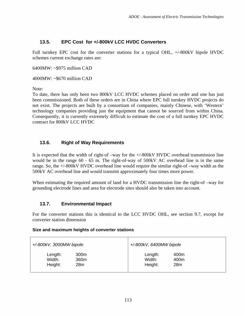
ADOE - Assessment of Electric Transmission Technologies
113
13.5. EPC Cost for +/-800kV LCC HVDC Converters
Full turnkey EPC cost for the converter stations for a typical OHL, +/-800kV bipole HVDC schemes current exchange rates are:
6400MW: ~$975 million CAD
4000MW: ~$670 million CAD
Note: To date, there has only been two 800kV LCC HVDC schemes placed on order and one has just been commissioned. Both of these orders are in China where EPC full turnkey HVDC projects do not exist. The projects are built by a consortium of companies, mainly Chinese, with ‘Western’ technology companies providing just the equipment that cannot be sourced from within China. Consequently, it is currently extremely difficult to estimate the cost of a full turnkey EPC HVDC contract for 800kV LCC HVDC
13.6. Right of Way Requirements It is expected that the width of right-of –way for the +/-800kV HVDC overhead transmission line would be in the range 60 - 65 m. The right-of-way of 500kV AC overhead line is in the same range. So, the +/-800kV HVDC overhead line would require the similar right-of –way width as the 500kV AC overhead line and would transmit approximately four times more power. When estimating the required amount of land for a HVDC transmission line the right-of –way for grounding electrode lines and area for electrode sites should also be taken into account.
13.7. Environmental Impact
For the converter stations this is identical to the LCC HVDC OHL, see section 9.7, except for converter station dimension
Size and maximum heights of converter stations
+/-800kV, 3000MW bipole
Length: 300m Width: 360m Height: 28m
+/-800kV, 6400MW bipole
Length: 400m Width: 400m Height: 28m
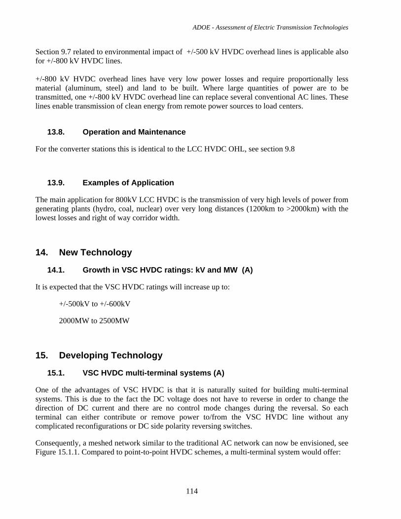
ADOE - Assessment of Electric Transmission Technologies
114
Section 9.7 related to environmental impact of +/-500 kV HVDC overhead lines is applicable also for +/-800 kV HVDC lines. +/-800 kV HVDC overhead lines have very low power losses and require proportionally less material (aluminum, steel) and land to be built. Where large quantities of power are to be transmitted, one +/-800 kV HVDC overhead line can replace several conventional AC lines. These lines enable transmission of clean energy from remote power sources to load centers.
13.8. Operation and Maintenance
For the converter stations this is identical to the LCC HVDC OHL, see section 9.8
13.9. Examples of Application
The main application for 800kV LCC HVDC is the transmission of very high levels of power from generating plants (hydro, coal, nuclear) over very long distances (1200km to >2000km) with the lowest losses and right of way corridor width.
14. New Technology
14.1. Growth in VSC HVDC ratings: kV and MW (A)
It is expected that the VSC HVDC ratings will increase up to:
+/-500kV to +/-600kV
2000MW to 2500MW
15. Developing Technology
15.1. VSC HVDC multi-terminal systems (A)
One of the advantages of VSC HVDC is that it is naturally suited for building multi-terminal systems. This is due to the fact the DC voltage does not have to reverse in order to change the direction of DC current and there are no control mode changes during the reversal. So each terminal can either contribute or remove power to/from the VSC HVDC line without any complicated reconfigurations or DC side polarity reversing switches.
Consequently, a meshed network similar to the traditional AC network can now be envisioned, see Figure 15.1.1. Compared to point-to-point HVDC schemes, a multi-terminal system would offer:
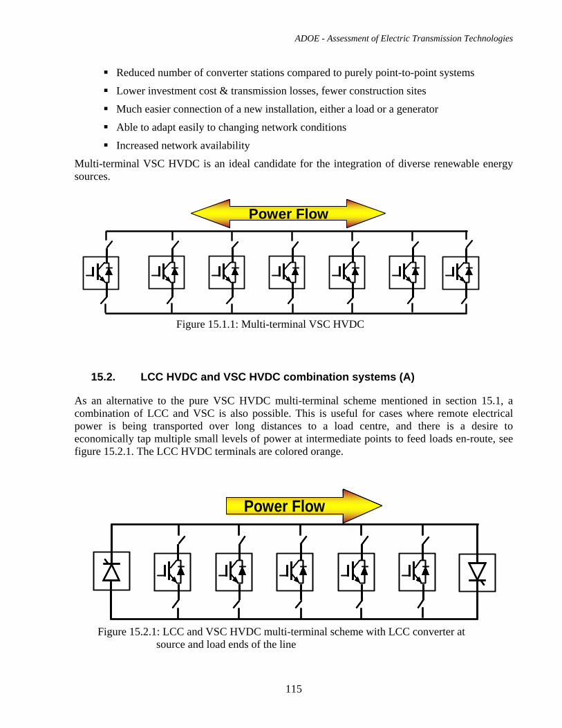
ADOE - Assessment of Electric Transmission Technologies
115
Reduced number of converter stations compared to purely point-to-point systems
Lower investment cost & transmission losses, fewer construction sites
Much easier connection of a new installation, either a load or a generator
Able to adapt easily to changing network conditions
Increased network availability
Multi-terminal VSC HVDC is an ideal candidate for the integration of diverse renewable energy sources.
15.2. LCC HVDC and VSC HVDC combination systems (A)
As an alternative to the pure VSC HVDC multi-terminal scheme mentioned in section 15.1, a combination of LCC and VSC is also possible. This is useful for cases where remote electrical power is being transported over long distances to a load centre, and there is a desire to economically tap multiple small levels of power at intermediate points to feed loads en-route, see figure 15.2.1. The LCC HVDC terminals are colored orange.
Power FlowPower Flow
Figure 15.1.1: Multi-terminal VSC HVDC
Power FlowPower FlowPower Flow
Figure 15.2.1: LCC and VSC HVDC multi-terminal scheme with LCC converter at source and load ends of the line
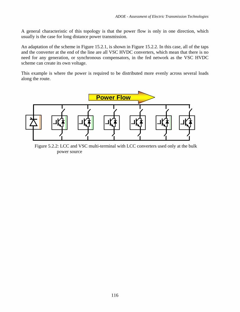
ADOE - Assessment of Electric Transmission Technologies
116
A general characteristic of this topology is that the power flow is only in one direction, which usually is the case for long distance power transmission.
An adaptation of the scheme in Figure 15.2.1, is shown in Figure 15.2.2. In this case, all of the taps and the converter at the end of the line are all VSC HVDC converters, which mean that there is no need for any generation, or synchronous compensators, in the fed network as the VSC HVDC scheme can create its own voltage.
This example is where the power is required to be distributed more evenly across several loads along the route.
Power FlowPower FlowPower Flow
Figure 5.2.2: LCC and VSC multi-terminal with LCC converters used only at the bulk power source
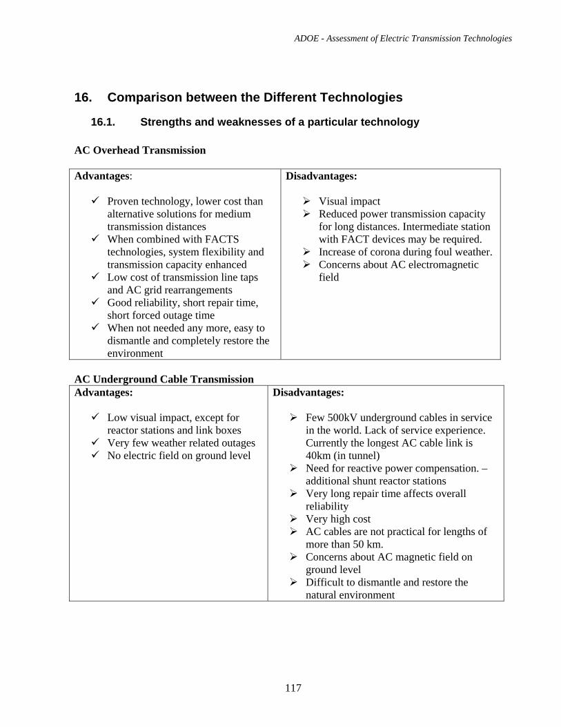
ADOE - Assessment of Electric Transmission Technologies
117
16. Comparison between the Different Technologies
16.1. Strengths and weaknesses of a particular technology AC Overhead Transmission Advantages:
Proven technology, lower cost than alternative solutions for medium transmission distances
When combined with FACTS technologies, system flexibility and transmission capacity enhanced
Low cost of transmission line taps and AC grid rearrangements
Good reliability, short repair time, short forced outage time
When not needed any more, easy to dismantle and completely restore the environment
Disadvantages:
Visual impact Reduced power transmission capacity
for long distances. Intermediate station with FACT devices may be required.
Increase of corona during foul weather. Concerns about AC electromagnetic
field
AC Underground Cable Transmission Advantages:
Low visual impact, except for reactor stations and link boxes
Very few weather related outages No electric field on ground level
Disadvantages:
Few 500kV underground cables in service in the world. Lack of service experience. Currently the longest AC cable link is 40km (in tunnel)
Need for reactive power compensation. – additional shunt reactor stations
Very long repair time affects overall reliability
Very high cost AC cables are not practical for lengths of
more than 50 km. Concerns about AC magnetic field on
ground level Difficult to dismantle and restore the
natural environment
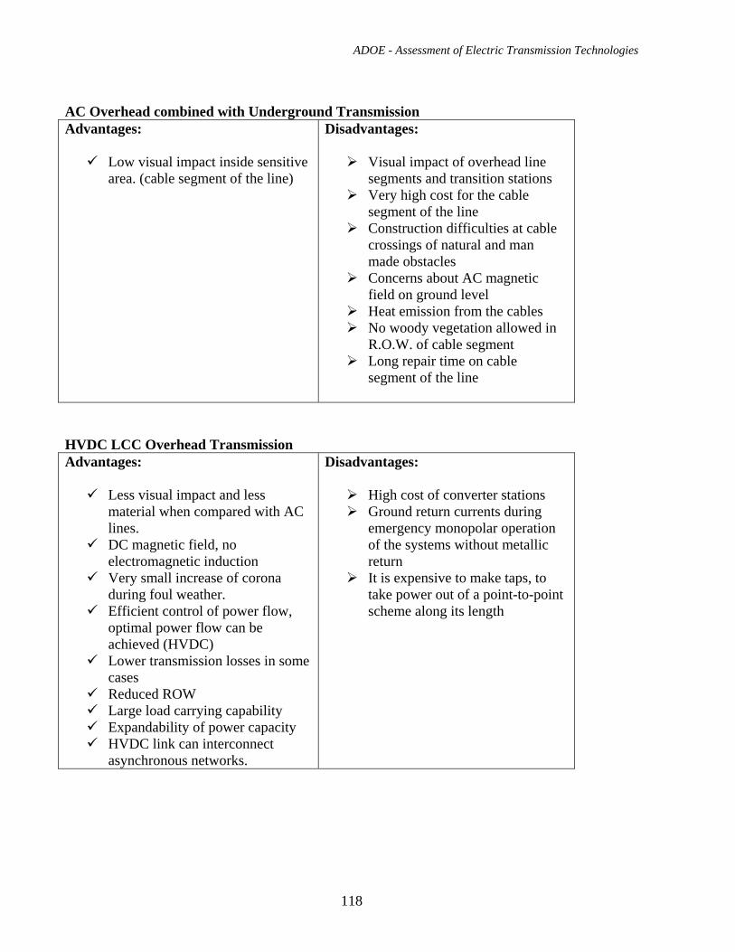
ADOE - Assessment of Electric Transmission Technologies
118
AC Overhead combined with Underground Transmission Advantages:
Low visual impact inside sensitive area. (cable segment of the line)
Disadvantages:
Visual impact of overhead line segments and transition stations
Very high cost for the cable segment of the line
Construction difficulties at cable crossings of natural and man made obstacles
Concerns about AC magnetic field on ground level
Heat emission from the cables No woody vegetation allowed in
R.O.W. of cable segment Long repair time on cable
segment of the line
HVDC LCC Overhead Transmission Advantages:
Less visual impact and less material when compared with AC lines.
DC magnetic field, no electromagnetic induction
Very small increase of corona during foul weather.
Efficient control of power flow, optimal power flow can be achieved (HVDC)
Lower transmission losses in some cases
Reduced ROW Large load carrying capability Expandability of power capacity HVDC link can interconnect
asynchronous networks.
Disadvantages:
High cost of converter stations Ground return currents during
emergency monopolar operation of the systems without metallic return
It is expensive to make taps, to take power out of a point-to-point scheme along its length
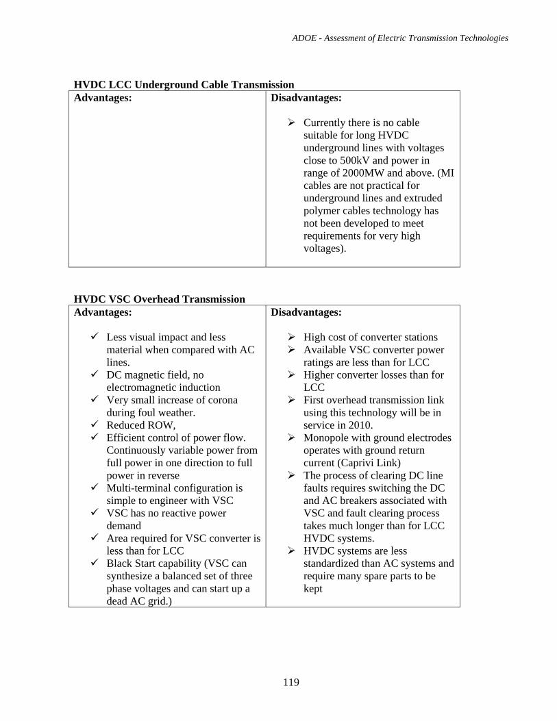
ADOE - Assessment of Electric Transmission Technologies
119
HVDC LCC Underground Cable Transmission Advantages:
Disadvantages:
Currently there is no cable suitable for long HVDC underground lines with voltages close to 500kV and power in range of 2000MW and above. (MI cables are not practical for underground lines and extruded polymer cables technology has not been developed to meet requirements for very high voltages).
HVDC VSC Overhead Transmission Advantages:
Less visual impact and less material when compared with AC lines.
DC magnetic field, no electromagnetic induction
Very small increase of corona during foul weather.
Reduced ROW, Efficient control of power flow.
Continuously variable power from full power in one direction to full power in reverse
Multi-terminal configuration is simple to engineer with VSC
VSC has no reactive power demand
Area required for VSC converter is less than for LCC
Black Start capability (VSC can synthesize a balanced set of three phase voltages and can start up a dead AC grid.)
Disadvantages:
High cost of converter stations Available VSC converter power
ratings are less than for LCC Higher converter losses than for
LCC First overhead transmission link
using this technology will be in service in 2010.
Monopole with ground electrodes operates with ground return current (Caprivi Link)
The process of clearing DC line faults requires switching the DC and AC breakers associated with VSC and fault clearing process takes much longer than for LCC HVDC systems.
HVDC systems are less standardized than AC systems and require many spare parts to be kept
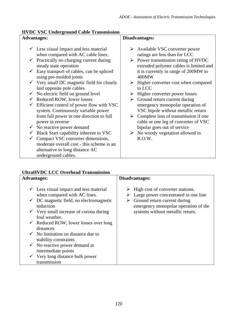
ADOE - Assessment of Electric Transmission Technologies
120
HVDC VSC Underground Cable Transmission Advantages:
Less visual impact and less material when compared with AC cable lines.
Practically no charging current during steady state operation
Easy transport of cables, can be spliced using pre-molded joints
Very small DC magnetic field for closely laid opposite pole cables
No electric field on ground level Reduced ROW, lower losses Efficient control of power flow with VSC
system. Continuously variable power from full power in one direction to full power in reverse
No reactive power demand Black Start capability inherent to VSC Compact VSC converter dimensions,
moderate overall cost - this scheme is an alternative to long distance AC underground cables.
Disadvantages:
Available VSC converter power ratings are less than for LCC
Power transmission rating of HVDC extruded polymer cables is limited and it is currently in range of 200MW to 400MW
Higher converter cost when compared to LCC
Higher converter power losses Ground return current during
emergency monopolar operation of VSC bipole without metallic return
Complete loss of transmission if one cable or one leg of converter of VSC bipolar goes out of service
No woody vegetation allowed in R.O.W.
UltraHVDC LCC Overhead Transmission Advantages:
Less visual impact and less material when compared with AC lines.
DC magnetic field, no electromagnetic induction
Very small increase of corona during foul weather.
Reduced ROW, lower losses over long distances
No limitation on distance due to stability constraints
No reactive power demand at intermediate points
Very long distance bulk power transmission
Disadvantages:
High cost of converter stations. Large power concentrated in one line Ground return current during
emergency monopolar operation of the systems without metallic return.
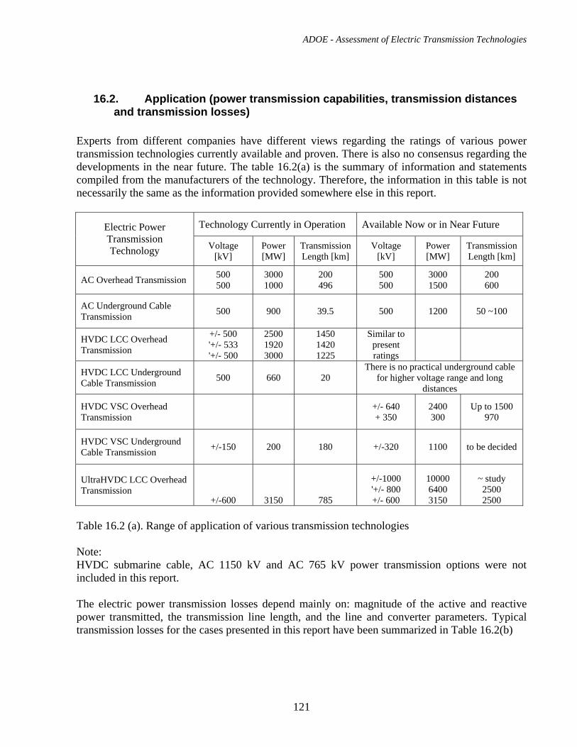
ADOE - Assessment of Electric Transmission Technologies
121
16.2. Application (power transmission capabilities, transmission distances and transmission losses)
Experts from different companies have different views regarding the ratings of various power transmission technologies currently available and proven. There is also no consensus regarding the developments in the near future. The table 16.2(a) is the summary of information and statements compiled from the manufacturers of the technology. Therefore, the information in this table is not necessarily the same as the information provided somewhere else in this report.
Technology Currently in Operation Available Now or in Near Future Electric Power Transmission Technology Voltage
[kV] Power [MW]
Transmission Length [km]
Voltage [kV]
Power [MW]
Transmission Length [km]
AC Overhead Transmission 500 500
3000 1000
200 496
500 500
3000 1500
200 600
AC Underground Cable Transmission 500 900 39.5 500 1200 50 ~100
HVDC LCC Overhead Transmission
+/- 500 '+/- 533 '+/- 500
2500 1920 3000
1450 1420 1225
Similar to present ratings
HVDC LCC Underground Cable Transmission 500 660 20
There is no practical underground cable for higher voltage range and long
distances
HVDC VSC Overhead Transmission +/- 640
+ 350 2400 300
Up to 1500 970
HVDC VSC Underground Cable Transmission +/-150 200 180 +/-320 1100 to be decided
UltraHVDC LCC Overhead Transmission
+/-600 3150 785
+/-1000 '+/- 800 +/- 600
10000 6400 3150
~ study 2500 2500
Table 16.2 (a). Range of application of various transmission technologies Note: HVDC submarine cable, AC 1150 kV and AC 765 kV power transmission options were not included in this report. The electric power transmission losses depend mainly on: magnitude of the active and reactive power transmitted, the transmission line length, and the line and converter parameters. Typical transmission losses for the cases presented in this report have been summarized in Table 16.2(b)
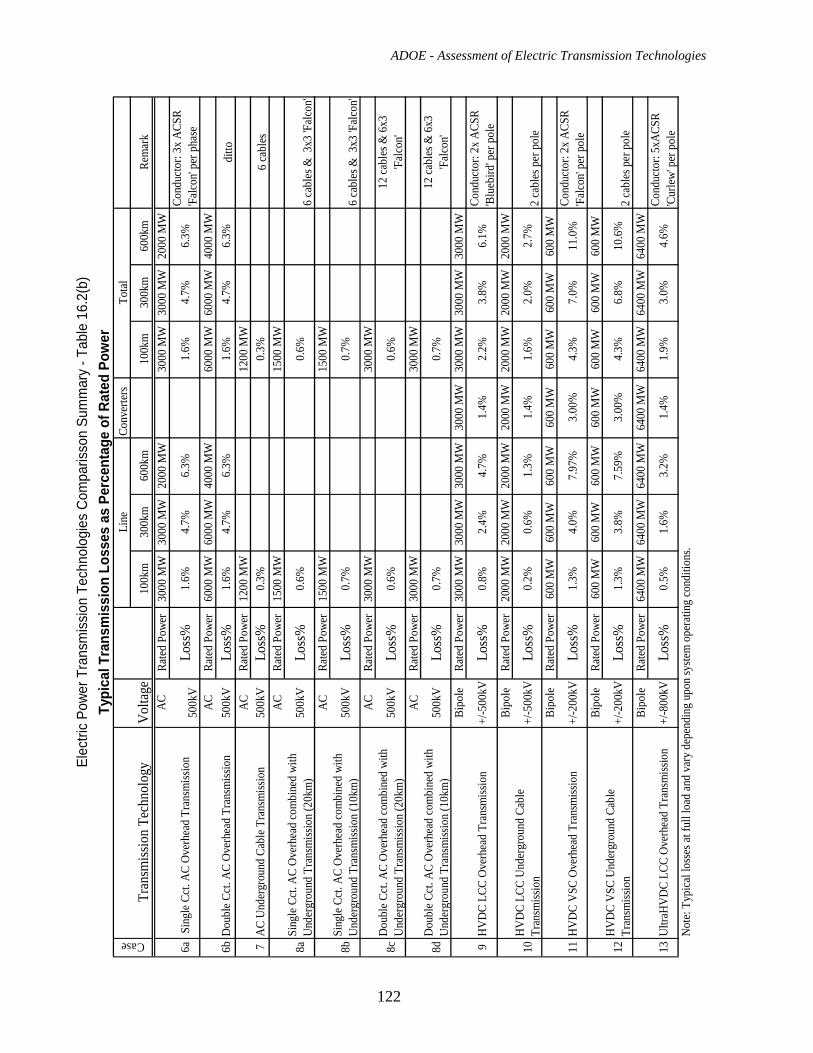
ADOE - Assessment of Electric Transmission Technologies
122
Elec
tric
Powe
r Tra
nsm
issio
n Te
chno
logi
es C
ompa
risso
n Su
mm
ary
- Tab
le 1
6.2(
b)Ty
pica
l Tra
nsm
issi
on L
osse
s as
Per
cent
age
of R
ated
Pow
erLi
neCo
nver
ters
Tota
l
Tran
smiss
ion
Tech
nolo
gyV
olta
ge10
0km
300k
m60
0km
100k
m30
0km
600k
mRe
mar
kAC
Rate
d Po
wer
3000
MW
3000
MW
2000
MW
3000
MW
3000
MW
2000
MW
6a S
ingl
e Cct
. AC
Ove
rhea
d Tr
ansm
issio
n50
0kV
Loss
%1.
6%4.
7%6.
3%1.
6%4.
7%6.
3%Co
nduc
tor:
3x A
CSR
'Fal
con'
per p
hase
AC
Rate
d Po
wer
6000
MW
6000
MW
4000
MW
6000
MW
6000
MW
4000
MW
6bD
oubl
e Cct
. AC
Ove
rhea
d Tr
ansm
issio
n50
0kV
Loss
%1.
6%4.
7%6.
3%1.
6%4.
7%6.
3%di
ttoAC
Rate
d Po
wer
1200
MW
1200
MW
7AC
Und
ergr
ound
Cab
le T
rans
miss
ion
500k
VLo
ss%
0.3%
0.3%
6 ca
bles
ACRa
ted
Powe
r15
00 M
W15
00 M
W
8aSi
ngle
Cct
. AC
Ove
rhea
d co
mbi
ned
with
U
nder
grou
nd T
rans
miss
ion
(20k
m)
500k
VLo
ss%
0.6%
0.6%
6 ca
bles
& 3
x3 'F
alco
n'AC
Rate
d Po
wer
1500
MW
1500
MW
8bSi
ngle
Cct
. AC
Ove
rhea
d co
mbi
ned
with
U
nder
grou
nd T
rans
miss
ion
(10k
m)
500k
VLo
ss%
0.7%
0.7%
6 ca
bles
& 3
x3 'F
alco
n'AC
Rate
d Po
wer
3000
MW
3000
MW
8cD
oubl
e Cct
. AC
Ove
rhea
d co
mbi
ned
with
U
nder
grou
nd T
rans
miss
ion
(20k
m)
500k
VLo
ss%
0.6%
0.6%
12 ca
bles
& 6
x3
'Fal
con'
ACRa
ted
Powe
r30
00 M
W30
00 M
W
8dD
oubl
e Cct
. AC
Ove
rhea
d co
mbi
ned
with
U
nder
grou
nd T
rans
miss
ion
(10k
m)
500k
VLo
ss%
0.7%
0.7%
12 ca
bles
& 6
x3
'Fal
con'
Bipo
leRa
ted
Powe
r30
00 M
W30
00 M
W30
00 M
W30
00 M
W30
00 M
W30
00 M
W30
00 M
W
9H
VD
C LC
C O
verh
ead
Tran
smiss
ion
+/-5
00kV
Loss
%0.
8%2.
4%4.
7%1.
4%2.
2%3.
8%6.
1%Co
nduc
tor:
2x A
CSR
'Blu
ebird
' per
pol
e Bi
pole
Rate
d Po
wer
2000
MW
2000
MW
2000
MW
2000
MW
2000
MW
2000
MW
2000
MW
10H
VD
C LC
C U
nder
grou
nd C
able
Tr
ansm
issio
n+/
-500
kVLo
ss%
0.2%
0.6%
1.3%
1.4%
1.6%
2.0%
2.7%
2 ca
bles
per
pol
eBi
pole
Rate
d Po
wer
600
MW
600
MW
600
MW
600
MW
600
MW
600
MW
600
MW
11H
VD
C V
SC O
verh
ead
Tran
smiss
ion
+/-2
00kV
Loss
%1.
3%4.
0%7.
97%
3.00
%4.
3%7.
0%11
.0%
Cond
ucto
r: 2x
ACS
R 'F
alco
n' pe
r pol
e Bi
pole
Rate
d Po
wer
600
MW
600
MW
600
MW
600
MW
600
MW
600
MW
600
MW
12H
VD
C V
SC U
nder
grou
nd C
able
Tr
ansm
issio
n +/
-200
kVLo
ss%
1.3%
3.8%
7.59
%3.
00%
4.3%
6.8%
10.6
%2
cabl
es p
er p
ole
Bipo
leRa
ted
Powe
r64
00 M
W64
00 M
W64
00 M
W64
00 M
W64
00 M
W64
00 M
W64
00 M
W
13U
ltraH
VD
C LC
C O
verh
ead
Tran
smiss
ion
+/-8
00kV
Loss
%0.
5%1.
6%3.
2%1.
4%1.
9%3.
0%4.
6%Co
nduc
tor:
5xAC
SR
'Cur
lew'
per
pol
e N
ote:
Typ
ical
loss
es at
full
load
and
vary
dep
endi
ng u
pon
syste
m o
pera
ting
cond
ition
s.
Case
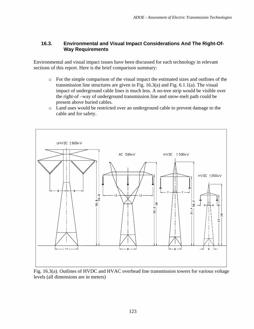
ADOE - Assessment of Electric Transmission Technologies
123
16.3. Environmental and Visual Impact Considerations And The Right-Of-Way Requirements
Environmental and visual impact issues have been discussed for each technology in relevant sections of this report. Here is the brief comparison summary:
o For the simple comparison of the visual impact the estimated sizes and outlines of the transmission line structures are given in Fig. 16.3(a) and Fig. 6.1.1(a). The visual impact of underground cable lines is much less. A no-tree strip would be visible over the right-of –way of underground transmission line and snow-melt path could be present above buried cables.
o Land uses would be restricted over an underground cable to prevent damage to the cable and for safety.
Fig. 16.3(a). Outlines of HVDC and HVAC overhead line transmission towers for various voltage levels (all dimensions are in meters)
ADOE - Assessment of Electric Transmission Technologies
124
o Underground cables do not generate electric fields on the ground surface. Overhead
HVAC and HVDC lines generate electric fields. The electric field exposure limits are more stringent for HVAC lines.
o Both overhead and underground lines generate magnetic fields at ground level. The magnetic field from cable line is limited to narrow area above the cable line. The magnetic field exposure limits are more stringent for HVAC lines.
o Audible noise from HVDC overhead lines increases during fair weather and decreases during foul weather unlike the noise levels on HVAC overhead lines. Underground cables cause no audible noise
o Overhead lines can cause radio interference inside their R-O-W. Radio interference levels from HVDC lines are usually 6–8 dB lower than those of HVAC lines of similar voltage.
o Ground currents flow during monopole operation of HVDC overhead/underground line if metallic return is not provided.
o The comparison of required right of way widths and station areas has been given in Table 17(a).
16.4. Costs Of Particular Technology – Cost Breakdown for Various Study Cases
In order to make a meaningful comparison of costs for various technologies, twelve cost study cases have been assumed for the purpose of this report. These study cases are listed in Table 17(a) (Section 17) and marked as; 6a, 6b, 7, 8a, 8b, 8c, 8d, 9, 10, 11, 12 and 13. The number of each cost study case points to the section of the report where the relevant technology has been described. The illustrations of each cost study case are shown in Fig. 16.4.(a) for easy understanding. The total cost for each study case is a function of transmission line cost per kilometer, transmission line length and required quantities of various transmission infrastructure components and their costs. Tables 16.4a, 16.4b and 16.4c show the breakdown of total cost for each study case for transmission line lengths of 50 km 100 km, 300 km and 600 km. The costs of the components have been taken from the relevant sections of this report.
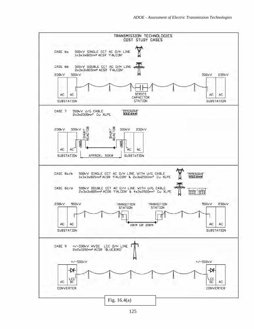
ADOE - Assessment of Electric Transmission Technologies
125
Fig. 16.4(a)
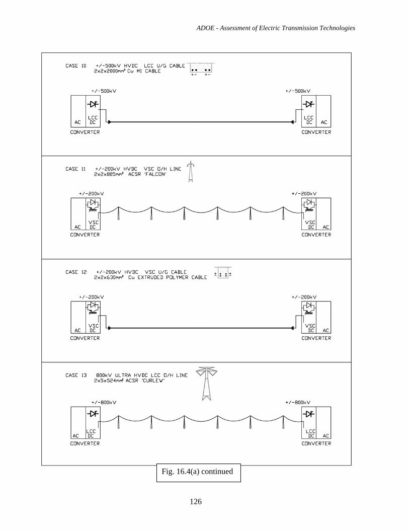
ADOE - Assessment of Electric Transmission Technologies
126
Fig. 16.4(a) continued
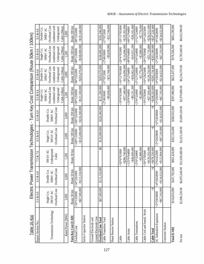
ADOE - Assessment of Electric Transmission Technologies
127
Tabl
e 16
.4(a
)El
ectri
c Po
wer T
rans
miss
ion
Tech
nolo
gies
- Tu
rn K
ey C
ost C
ompa
rison
(Rou
te 5
0km
/ 10
0km
)Re
port
Secti
on N
o.:
6.5 &
6.6
6.5
& 6
.67.
5 &
7.6
6.5
& 6
.66.
5 &
6.6
8.5 &
6.6
8.5 &
6.6
8.5 &
6.6
8.5 &
6.6
Tran
smiss
ion T
echn
olog
ySi
ngle
Cct.
500
kV A
C Ov
erhe
ad L
ine
Dou
ble C
ct.
500k
V AC
Ov
erhe
ad L
ine
500
kV A
C Un
derg
roun
d Ca
ble
Sing
le Cc
t.
50
0 kV
AC
Over
head
Lin
e
Dou
ble C
ct.
500k
V AC
Ov
erhe
ad L
ine
Sing
le Cc
t. 50
0kV
AC
Over
head
Lin
e co
mbi
ned
with
Un
derg
roun
d Ca
ble (
10km
)
Dou
ble C
ct.
500k
V AC
Ov
erhe
ad L
ine
com
bine
d with
Un
derg
roun
d Ca
ble (
10km
)
Sing
le Cc
t. 50
0kV
AC
Over
head
Lin
e co
mbi
ned w
ith
Unde
rgro
und
Cabl
e (20
km)
Dou
ble C
ct.
500k
V AC
Ov
erhe
ad L
ine
comb
ined
with
Un
derg
roun
d Ca
ble (
20km
)Ra
ted P
ower
[MW
]3,
000
6,000
1,200
3,000
6,000
1,50
03,
000
1,50
03,
000
Turn
Key
Cos
t [CA
D]Ro
ute 5
0 km
Rout
e 50
kmRo
ute 5
0 km
Rout
e 100
kmRo
ute 1
00 km
Rout
e 100
kmRo
ute 1
00 km
Rout
e 100
kmRo
ute 1
00 km
Over
head
Lin
e=5
0*13
5000
0=5
0*22
6300
0=1
00*1
3500
00=1
00*2
2630
00=9
0*13
5000
0=9
0*22
6300
0=8
0*13
5000
0=8
0*22
6300
0=$
67,5
00,00
0=$
113,1
50,00
0=$
135,0
00,00
0=$
226,3
00,00
0=$
121,5
00,0
00=$
203,
670,
000
=$10
8,00
0,00
0=$
181,
040,
000
Serie
s Cap
acito
r Stat
ion
Grou
nd E
lectro
de an
d Gr
ound
Elec
trode
Lin
eO
verh
ead
Line
Tot
al$6
7,50
0,000
$113
,150
,000
$0$1
35,0
00,00
0$2
26,30
0,00
0$1
21,50
0,00
0$2
03,6
70,0
00$1
08,0
00,0
00$1
81,0
40,0
00Ca
ble T
rans
ition
Yar
d=2
*491
9000
=2*7
8720
00=2
*491
9000
=2*7
8720
00=$
9,838
,000
=$15
,744
,000
=$9,
838,
000
=$15
,744
,000
Shun
t Rea
ctor S
tatio
n
Cabl
e =5
0*6*
9558
00=1
0*6*
9558
00=1
0*12
*955
800
=20*
6*95
5800
=20*
12*9
5580
0=$
286,
740,0
00=$
57,34
8,00
0=$
114,
696,
000
=$11
4,69
6,00
0=$
229,
392,
000
Cabl
e Joi
nts
=125
*6*6
4800
=24*
6*64
800
=24*
12*6
4800
=49*
6*64
800
=49*
12*6
4800
=$48
,600
,000
=$9,3
31,2
00=$
18,6
62,4
00=$
19,0
51,2
00=$
38,1
02,4
00Ca
ble T
emin
ation
s=2
*6*3
2400
0=2
*6*3
2400
0=2
*12*
3240
00=2
*6*3
2400
0=2
*12*
3240
00=$
3,88
8,000
=$3,8
88,0
00=$
7,77
6,00
0=$
3,88
8,00
0=$
7,77
6,00
0Ca
ble C
ivil
and I
nstal
l. W
ork
=50*
2785
840
=10*
2785
840
=10*
1282
5600
=20*
2785
840
=20*
1282
5600
=$13
9,29
2,000
=$27
,858,
400
=$12
8,25
6,00
0=$
55,7
16,8
00=$
256,
512,
000
Cabl
e Tot
al
=$=$
=$47
8,52
0,000
=$=$
=$10
8,263
,600
=$28
5,13
4,40
0=$
203,
190,
000
=$54
7,52
6,40
0AC
Sub
statio
n Exp
ansio
n=2
*336
5800
0=4
*336
5800
0=2
*614
5200
0=2
*336
5800
0=4
*336
5800
0=2
*336
5800
0=4
*336
5800
0=2
*336
5800
0=4
*336
5800
0=$
67,3
16,00
0=$
134,6
32,00
0=$
122,
904,0
00=$
67,3
16,00
0=$
134,6
32,00
0=$
67,31
6,00
0=$
134,
632,
000
=$67
,316
,000
=$13
4,63
2,00
0Co
nver
ter S
tatio
n
Tota
l [CA
D]$1
34,8
16,00
0$2
47,7
82,00
0$6
01,4
24,00
0$2
02,3
16,00
0$3
60,93
2,00
0$2
97,08
0,00
0$6
23,4
37,0
00$3
78,5
06,0
00$8
63,1
99,0
00
Per k
m$2
,696
,320
.00
$4,9
55,6
40.00
$12,
028,
480.
00$2
,023
,160
.00$3
,609
,320
.00$2
,970
,800.
00$6
,234,3
70.0
0$3
,785,
060.
00$8
,631,
990.
00
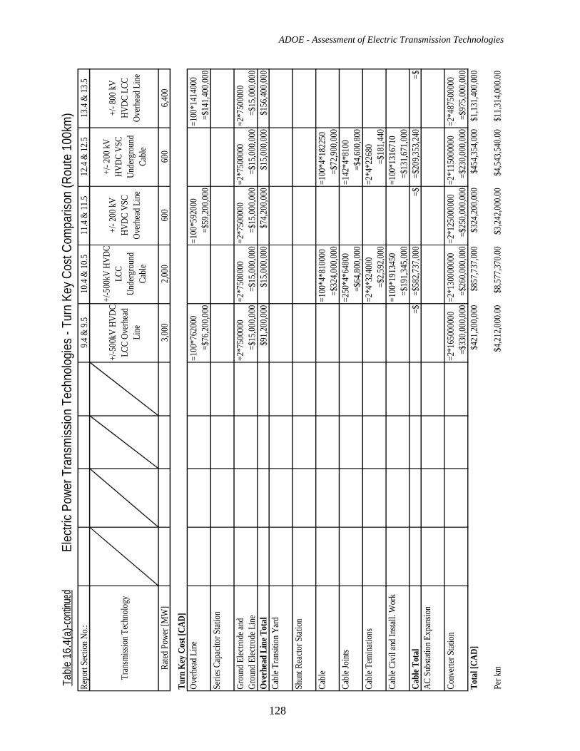
ADOE - Assessment of Electric Transmission Technologies
128
Table
16.
4(a)
-conti
nued
Elec
tric
Powe
r Tra
nsm
ission
Tec
hnolo
gies
- Tur
n Ke
y Cos
t Com
paris
on (R
oute
100
km)
Repo
rt Se
ction
No.:
9.4
& 9.
510
.4 &
10.5
11.4
& 11
.512
.4 &
12.5
13.4
& 13
.5
Tran
smiss
ion T
echn
olog
y+/
-500
kV H
VDC
LCC
Over
head
Li
ne
+/-5
00kV
HVD
C LC
C Un
derg
roun
d Ca
ble
+/- 2
00 kV
HV
DC V
SC
Over
head
Lin
e
+/- 2
00 kV
HV
DC V
SC
Unde
rgro
und
Cabl
e
+/- 8
00 kV
HV
DC L
CC
Over
head
Lin
e
Rated
Pow
er [M
W]
3,000
2,000
600
600
6,400
Turn
Key
Cos
t [CA
D]Ov
erhe
ad L
ine
=100
*762
000
=100
*592
000
=100
*141
4000
=$76
,200,0
00=$
59,20
0,000
=$14
1,400
,000
Serie
s Cap
acito
r Stat
ion
Grou
nd E
lectro
de an
d =2
*750
0000
=2*7
5000
00=2
*750
0000
=2*7
5000
00=2
*750
0000
Grou
nd E
lectro
de L
ine
=$15
,000,0
00=$
15,00
0,000
=$15
,000,0
00=$
15,00
0,000
=$15
,000,0
00O
verh
ead
Line
Tot
al$9
1,200
,000
$15,0
00,00
0$7
4,200
,000
$15,0
00,00
0$1
56,40
0,000
Cabl
e Tra
nsiti
on Y
ard
Shun
t Rea
ctor S
tatio
n
Cabl
e =1
00*4
*810
000
=100
*4*1
8225
0=$
324,0
00,00
0=$
72,90
0,000
Cabl
e Joi
nts
=250
*4*6
4800
=142
*4*8
100
=$64
,800,0
00=$
4,600
,800
Cabl
e Tem
inati
ons
=2*4
*324
000
=2*4
*226
80=$
2,592
,000
=$18
1,440
Cabl
e Civ
il an
d Ins
tall.
Wor
k=1
00*1
9134
50=1
00*1
3167
10=$
191,3
45,00
0=$
131,6
71,00
0Ca
ble T
otal
=$
=$58
2,737
,000
=$=$
209,3
53,24
0=$
AC S
ubsta
tion E
xpan
sion
Conv
erter
Stat
ion
=2*1
6500
0000
=2*1
3000
0000
=2*1
2500
0000
=2*1
1500
0000
=2*4
8750
0000
=$33
0,000
,000
=$26
0,000
,000
=$25
0,000
,000
=$23
0,000
,000
=$97
5,000
,000
Tota
l [CA
D]$4
21,20
0,000
$857
,737,0
00$3
24,20
0,000
$454
,354,0
00$1
,131,4
00,00
0
Per k
m$4
,212,0
00.00
$8,57
7,370
.00$3
,242,0
00.00
$4,54
3,540
.00$1
1,314
,000.0
0
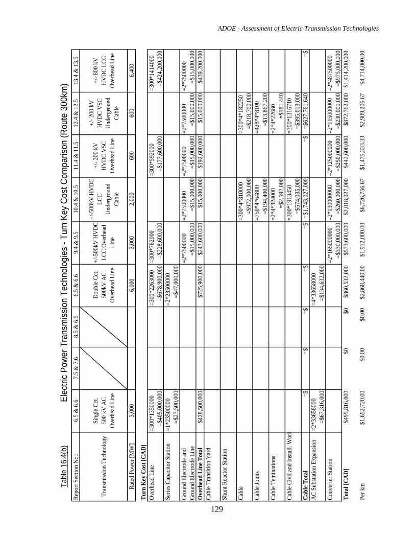
ADOE - Assessment of Electric Transmission Technologies
129
Tabl
e 16
.4(b
)El
ectri
c Po
wer T
rans
miss
ion
Tech
nolo
gies
- Tu
rn K
ey C
ost C
ompa
rison
(Rou
te 3
00km
)Re
port
Secti
on N
o.:
6.5
& 6
.67.
5 &
7.6
8.5
& 6
.66.
5 &
6.6
9.4
& 9
.510
.4 &
10.
511
.4 &
11.
512
.4 &
12.
513
.4 &
13.
5
Tran
smiss
ion
Tech
nolo
gySi
ngle
Cct.
500
kV A
C Ov
erhe
ad L
ine
Dou
ble C
ct.
500k
V AC
Ov
erhe
ad L
ine
+/-5
00kV
HVD
C LC
C Ov
erhe
ad
Line
+/-5
00kV
HVD
C LC
C Un
derg
roun
d Ca
ble
+/- 2
00 k
V HV
DC V
SC
Over
head
Lin
e
+/- 2
00 k
V HV
DC V
SC
Unde
rgro
und
Cabl
e
+/- 8
00 k
V HV
DC L
CC
Over
head
Lin
e
Rated
Pow
er [M
W]
3,00
06,
000
3,00
02,
000
600
600
6,40
0
Turn
Key
Cos
t [CA
D]Ov
erhe
ad L
ine
=300
*135
0000
=300
*226
3000
=300
*762
000
=300
*592
000
=300
*141
4000
=$40
5,00
0,00
0=$
678,
900,
000
=$22
8,60
0,00
0=$
177,
600,
000
=$42
4,20
0,00
0Se
ries C
apac
itor S
tatio
n=1
*235
0000
0=2
*235
0000
0=$
23,5
00,0
00=$
47,0
00,0
00Gr
ound
Elec
trode
and
=2*7
5000
00=2
*750
0000
=2*7
5000
00=2
*750
0000
=2*7
5000
00Gr
ound
Elec
trode
Lin
e=$
15,0
00,0
00=$
15,0
00,0
00=$
15,0
00,0
00=$
15,0
00,0
00=$
15,0
00,0
00O
verh
ead
Line
Tot
al$4
28,5
00,0
00$7
25,9
00,0
00$2
43,6
00,0
00$1
5,00
0,00
0$1
92,6
00,0
00$1
5,00
0,00
0$4
39,2
00,0
00Ca
ble T
rans
ition
Yar
d
Shun
t Rea
ctor S
tatio
n
Cabl
e =3
00*4
*810
000
=300
*4*1
8225
0=$
972,
000,
000
=$21
8,70
0,00
0Ca
ble J
oint
s=7
50*4
*648
00=4
28*4
*810
0=$
194,
400,
000
=$13
,867
,200
Cabl
e Tem
inati
ons
=2*4
*324
000
=2*4
*226
80=$
2,59
2,00
0=$
181,
440
Cabl
e Civ
il an
d In
stall.
Wor
k=3
00*1
9134
50=3
00*1
3167
10=$
574,
035,
000
=$39
5,01
3,00
0Ca
ble T
otal
=$
=$=$
=$=$
=$1,
743,
027,
000
=$=$
627,
761,
640
=$AC
Sub
statio
n Ex
pans
ion
=2*3
3658
000
=4*3
3658
000
=$67
,316
,000
=$13
4,63
2,00
0Co
nver
ter S
tatio
n =2
*165
0000
00=2
*130
0000
00=2
*125
0000
00=2
*115
0000
00=2
*487
5000
00=$
330,
000,
000
=$26
0,00
0,00
0=$
250,
000,
000
=$23
0,00
0,00
0=$
975,
000,
000
Tota
l [CA
D]$4
95,8
16,0
00$0
$0$8
60,5
32,0
00$5
73,6
00,0
00$2
,018
,027
,000
$442
,600
,000
$872
,762
,000
$1,4
14,2
00,0
00
Per k
m$1
,652
,720
.00
$0.0
0$0
.00
$2,8
68,4
40.0
0$1
,912
,000
.00
$6,7
26,7
56.6
7$1
,475
,333
.33
$2,9
09,2
06.6
7$4
,714
,000
.00
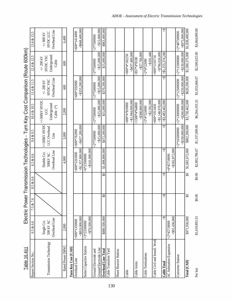
ADOE - Assessment of Electric Transmission Technologies
130
Tabl
e 16
.4(c
)El
ectri
c Po
wer T
rans
miss
ion
Tech
nolo
gies
- Tu
rn K
ey C
ost C
ompa
rison
(Rou
te 6
00km
)Re
port
Secti
on N
o.:
6.5 &
6.6
7.5 &
7.6
8.5 &
6.6
6.5 &
6.6
9.4 &
9.5
10.4
& 10
.511
.4 &
11.5
12.4
& 12
.513
.4 &
13.5
Tran
smiss
ion T
echn
olog
ySi
ngle
Cct.
500 k
V AC
Ov
erhe
ad L
ine
Dou
ble C
ct.
500k
V AC
Ov
erhe
ad L
ine
+/-5
00kV
HVD
C LC
C Ov
erhe
ad
Line
+/-5
00kV
HVD
C
LCC
Unde
rgro
und
Cabl
e (*
)
+/- 2
00 kV
HV
DC V
SC
Over
head
Lin
e
+/- 2
00 kV
HV
DC V
SC
Unde
rgro
und
Cabl
e
+/- 8
00 kV
HV
DC L
CC
Over
head
Lin
e
Rated
Pow
er [M
W]
2,000
4,00
03,
000
2,000
600
600
6,400
Turn
Key
Cos
t [CA
D]Ov
erhe
ad L
ine
=600
*135
0000
=600
*226
3000
=600
*762
000
=600
*592
000
=600
*141
4000
=$81
0,000
,000
=$1,3
57,80
0,00
0=$
457,
200,0
00=$
355,2
00,00
0=$
848,4
00,00
0Se
ries C
apac
itor S
tatio
n=3
*235
0000
0=6
*235
0000
0=$
70,50
0,00
0=$
141,0
00,00
0Gr
ound
Elec
trode
and
=2*7
5000
00=2
*750
0000
=2*7
5000
00=2
*750
0000
=2*7
5000
00Gr
ound
Elec
trode
Lin
e=$
15,00
0,000
=$15
,000,
000
=$15
,000,0
00=$
15,0
00,0
00=$
15,00
0,00
0O
verh
ead
Line
Tot
al$8
80,50
0,00
0$0
$0$1
,498,8
00,0
00$4
72,20
0,000
$15,
000,
000
$370
,200,0
00$1
5,00
0,00
0$8
63,40
0,00
0Ca
ble T
rans
ition
Yar
d
Shun
t Rea
ctor S
tatio
n
Cabl
e =6
00*4
*810
000
=600
*4*1
8225
0=$
1,944
,000
,000
=$43
7,40
0,00
0Ca
ble J
oint
s=1
500*
4*64
800
=857
*4*8
100
=$38
8,80
0,00
0=$
27,7
66,8
00Ca
ble T
emin
ation
s=2
*4*3
2400
0=2
*4*2
2680
=$2,
592,0
00=$
181,4
40Ca
ble C
ivil
and I
nstal
l. W
ork
=600
*191
3450
=600
*131
6710
=$1,1
48,0
70,0
00=$
790,
026,
000
Cabl
e Tot
al
=$=$
=$=$
=$=$
3,483
,462
,000
=$=$
1,25
5,37
4,24
0=$
AC S
ubsta
tion E
xpan
sion
=2*4
5718
000
=4*4
5718
000
=$91
,436,
000
=$18
2,872
,000
Conv
erter
Stat
ion
=2*1
6500
0000
=2*1
3000
0000
=2*1
2500
0000
=2*1
1500
0000
=2*4
8750
0000
=$33
0,000
,000
=$26
0,00
0,00
0=$
250,0
00,00
0=$
230,
000,
000
=$97
5,000
,000
Tota
l [CA
D]$9
71,93
6,00
0$0
$0$1
,681,6
72,0
00$8
02,20
0,000
$3,75
8,46
2,00
0$6
20,20
0,000
$1,5
00,3
75,0
00$1
,838,4
00,00
0
Per k
m$1
,619
,893.3
3$0
.00$0
.00
$2,8
02,78
6.67
$1,3
37,0
00.0
0$6
,264,1
03.33
$1,0
33,6
66.67
$2,50
0,625
.00$3
,064
,000.0
0
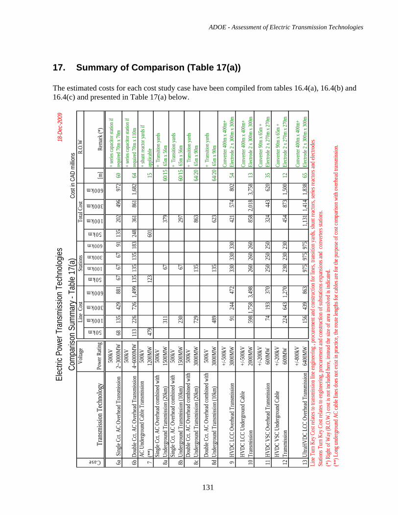
ADOE - Assessment of Electric Transmission Technologies
131
17. Summary of Comparison (Table 17(a)) The estimated costs for each cost study case have been compiled from tables 16.4(a), 16.4(b) and 16.4(c) and presented in Table 17(a) below.
Elec
tric P
ower
Tra
nsm
ission
Tec
hnolo
gies
18-D
ec-2
009
Com
paris
on S
umm
ary -
Tab
le 17
(a)
Cost
in CA
D m
illion
sVo
ltage
Line
Cos
tSt
ation
sTo
tal C
ost
R.O.
W
Case
Tran
smiss
ion T
echn
ology
Powe
r Rati
ng
50km
100km
300km
600km
50km
100km
300km
600km
50km
100km
300km
600km
[m]
Rema
rk (*
)
6a Si
ngle
Cct. A
C Ov
erhea
d Tran
smiss
ion50
0kV
2~30
00M
W68
135
429
881
6767
6791
135
202
496
972
60+ s
eries
capa
citor
stati
on if
req
uired
70m
x 70m
6bDo
uble
Cct. A
C Ov
erhea
d Tran
smiss
ion50
0kV
4~60
00M
W11
322
672
61,4
9913
513
513
518
324
836
186
11,6
8264
+ seri
es ca
pacit
or st
ation
if
requir
ed 70
m x 1
10m
7AC
Und
ergro
und C
able
Tran
smiss
ion
(**)
500k
V12
00M
W47
912
360
115
+ shu
nt rea
ctor y
ards i
f ap
plica
ble
8aSi
ngle
Cct. A
C Ov
erhea
d com
bined
with
Un
derg
roun
d Tran
smiss
ion (2
0km)
500k
V15
00M
W31
167
379
60/15
+ Tr
ansit
ion ya
rds
65m
x 56m
8bSi
ngle
Cct. A
C Ov
erhea
d com
bined
with
Un
derg
roun
d Tran
smiss
ion (1
0km)
500k
V15
00M
W23
067
297
60/15
+ Tr
ansit
ion ya
rds
65m
x 56m
8cDo
uble
Cct. A
C Ov
erhea
d com
bined
with
Un
derg
roun
d Tran
smiss
ion (2
0km)
500k
V30
00M
W72
913
586
364
/20+
Tran
sition
yard
s 65
m x 9
0m
8dDo
uble
Cct. A
C Ov
erhea
d com
bined
with
Un
derg
roun
d Tran
smiss
ion (1
0km)
500k
V30
00M
W48
913
562
364
/20+
Tran
sition
yard
s 65
m x 9
0m
9HV
DC L
CC O
verh
ead T
ransm
ission
+/-5
00kV
3000
MW
9124
447
233
033
033
042
157
480
254
Conv
erter
400m
x 40
0m+
Elec
trode
2 x 3
00m
x 300
m
10HV
DC L
CC U
nderg
roun
d Cab
le Tr
ansm
ission
+/-5
00kV
2000
MW
598
1,758
3,498
260
260
260
858
2,018
3,758
13Co
nvert
er 40
0m x
400m
+ El
ectro
de 2
x 300
m x 3
00m
11HV
DC V
SC O
verh
ead T
ransm
ission
+/-2
00kV
600M
W74
193
370
250
250
250
324
443
620
35Co
nvert
er 90
m x 6
5m +
Elec
trode
2 x 2
70m
x 270
m
12HV
DC V
SC U
nderg
roun
d Cab
le Tr
ansm
ission
+/
-200
kV60
0MW
224
643
1,270
230
230
230
454
873
1,500
12Co
nvert
er 90
m x 6
5m +
Elec
trode
2 x 2
70m
x 270
m
13Ul
traHV
DC L
CC O
verh
ead T
ransm
ission
+/-8
00kV
6400
MW
156
439
863
975
975
975
1,131
1,414
1,838
65Co
nvert
er 40
0m x
400m
+ El
ectro
de 2
x 300
m x 3
00m
Line
Tur
n Key
Cos
t rela
tes to
tran
smiss
ion lin
e eng
ineeri
ng , p
rocu
remen
t and
cons
tructi
on fo
r line
s, tra
nsiti
on ya
rds,
shun
t rea
ctors,
serie
s rea
ctors
and e
lectro
des
Stati
ons T
urn K
ey C
ost r
elates
to en
ginee
ring,
proc
urem
ent a
nd co
nstru
ction
of su
bstat
ions e
xpan
sions
and
conv
erters
stati
ons.
(*) R
ight o
f Way
(R.O
.W.)
cost
is no
t inclu
ded h
ere, in
stead
the s
ize of
area
invo
lved i
s ind
icated
.(*
*) L
ong u
nderg
roun
d AC
cable
lines
does
not e
xist in
prac
tice,
the ro
ute le
ngths
for c
ables
are f
or th
e pur
pose
of co
st co
mpari
son w
ith ov
erhea
d tran
smiss
ion.
ADOE - Assessment of Electric Transmission Technologies
132
18. Conclusions The primary alternatives by which large power transmission projects in Alberta can be implemented are overhead transmission lines or underground transmission cables, or combination of both and HVAC or HVDC technology. Brief conclusions on electric power transmission technologies considered in the cost study analysis of section 16.4 have been provided as follows: AC Overhead Transmission - Study Cases 6a and 6b Overhead line transmission is a good balance from a cost and technical perspective. AC 500 kV overhead transmission lines with the use of FACTS technologies will likely remain the main option for power transmission in Alberta. These transmission lines use standard North American construction methods and have a lower cost than alternative technologies. Where increased power capacity is required, double circuit construction can be implemented at a low incremental cost. Longer distance lines may require reactive power compensation. New lines are easily interconnected in electric power transmission systems. Damage to overhead lines will not result in long power outages because they are easy and quick to repair. AC Underground Cable Transmission - Study Case 7 AC underground transmission cables have been built in several world capitals or in areas that require special considerations. These cable lines are very expensive and are used in densely populated urban areas where there is limited right-of-way for overhead lines. There are very few installations of 500 kV AC cables. They can be used for relatively short distances. The longest line of about 40km route length has been built in Tokyo and has shunt reactors at its ends. For longer transmission distances, the aggregate cost of AC underground cable lines and associated reactive power compensation equipment becomes prohibitive. Repair of underground cables is difficult and requires a significant amount of time, therefore 500kV cable transmission lines are built with 100% redundancy. In built-up areas, cables must be installed in duct banks or tunnels. Combination of AC Overhead with Underground Cable Transmission - Study Cases 8a to 8d The undergrounding of a portion of high voltage AC overhead transmission line is not a simple solution but it is a feasible option. This solution is used where lines pass through densely populated urban and commercial areas where there is limited right-of-way for overhead transmission. Transition stations to connect the overhead line and underground cables have to be built at each end of underground cable segment. Depending on the conditions of the surrounding transmission system, compensation may be required even for relatively short cable segments (10 – 30 km). The cable segment of the line has to be constructed in a cable duct bank or a tunnel. Cable repair can take up to two months and during winter may take longer. For reliability reasons the cable segment of the line is built with 100% redundancy. HVDC LCC, Overhead Transmission - Study Case 9 HVDC overhead line cost is low but converter stations are expensive. Therefore, for the transmission of bulk power at longer distances the +/- 500kV HVDC overhead transmission line with LCC converters has a lower cost than a comparable HVAC option. The right-of-way of HVDC lines is significantly less than for the same capacity HVAC lines. HVDC maximizes
ADOE - Assessment of Electric Transmission Technologies
133
transmission capacity with reduced land-use impact. This option can also be selected to facilitate control of direction and flow of power or where asynchronous systems have to be connected. HVDC LCC systems are suitable for point-to-point power transmission. Implementing a tap in the middle of the line is expensive. Point-to-point HVDC LCC systems are expandable, which means that converter stations can be built in stages, reducing the initial cost impacts. HVDC LCC, Underground Cable Transmission - Study Case 10 Existing underground HVDC mass impregnated cables are actually part of a major submarine cable link. It is impracticable and too expensive to build HVDC mass impregnated cable underground links longer than 20km using the present jointing technology. HVDC cable, suitable for building underground lines for bulk power transmission over long distances, does not currently exist. Consequently, the cost estimates for case 10 in Table 17(a) are more of a hypothetical nature. HVDC VSC, Overhead Transmission - Study Case 11 This technology is expensive but offers advantages when it comes to integration of power systems. VSC may accommodate multi-terminal operation, enables simultaneous control of active and reactive power, and AC voltage control. At present HVDC overhead lines with VSC true bipole converters, are comparable with HVDC overhead transmission lines with conventional LCC converters; for the lower range of voltages and powers considered. It is expected that in the future HVDC VSC technologies will be used for overhead transmission voltages up to +/-640 kV for bipolar power ratings up to 2400MW. No VSC based HVDC overhead schemes have yet been put into service, although one scheme is currently in construction. HVDC VSC, Underground Cable Transmission - Case 12 The HVDC cables with VSC converters currently in service can transmit comparatively small amounts of power (in the range of 200 to 400 MW). The relative cost per MW of transmitted power is still high for this technology. The manufacturers of the technology advise that in the near future HVDC VSC technology can be used for underground transmission at voltages up to +/-400kV and power levels up to 1500MW. Ultra HVDC LCC, Overhead Transmission - Case 13 Ultra high voltage direct current (UHVDC) schemes, with +/- 800kV overhead transmission lines and LCC converters are options for large bulk power transmission. Currently this technology can be used for up to 6400MW, and for very long transmission distances. The first application of this technology anywhere in the world has just been commissioned in China. One additional UHVDC project is in progress in China and there are plans for +/- 800kV transmission in India and South Africa as well. Similar schemes can be used in Canada and USA to connect remote power generation to load centers. Considering present power generation capacity and power requirements in Alberta, it is unlikely that such scheme will be required in the foreseeable future.

ADOE - Assessment of Electric Transmission Technologies
134
ADOE - Assessment of Electric Transmission Technologies
135
APPENDIX – A, Technical Information from ABB

ADOE - Assessment of Electric Transmission Technologies
136
ADOE - Assessment of Electric Transmission Technologies
137
APPENDIX – B, Technical Information from SIEMENS