Embed Size (px)
Citation preview
ASSEMBLY INSTRUCTIONS
Version 2, Rev B
PCN 062811-10
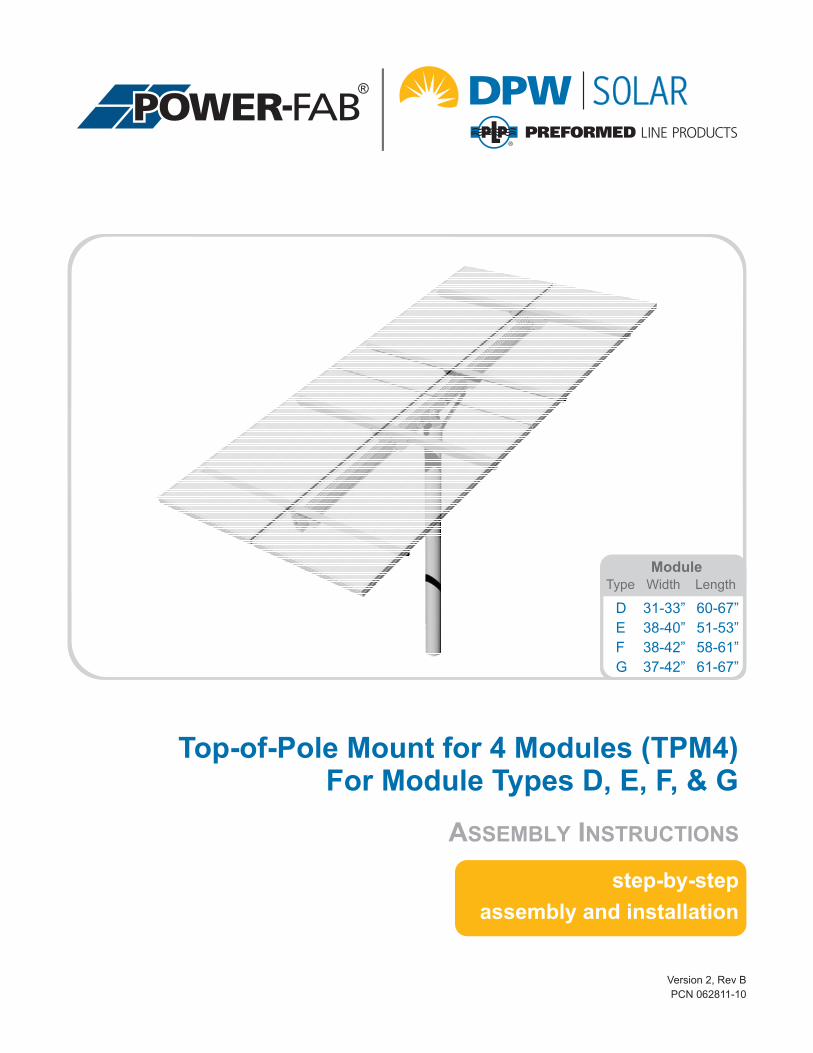
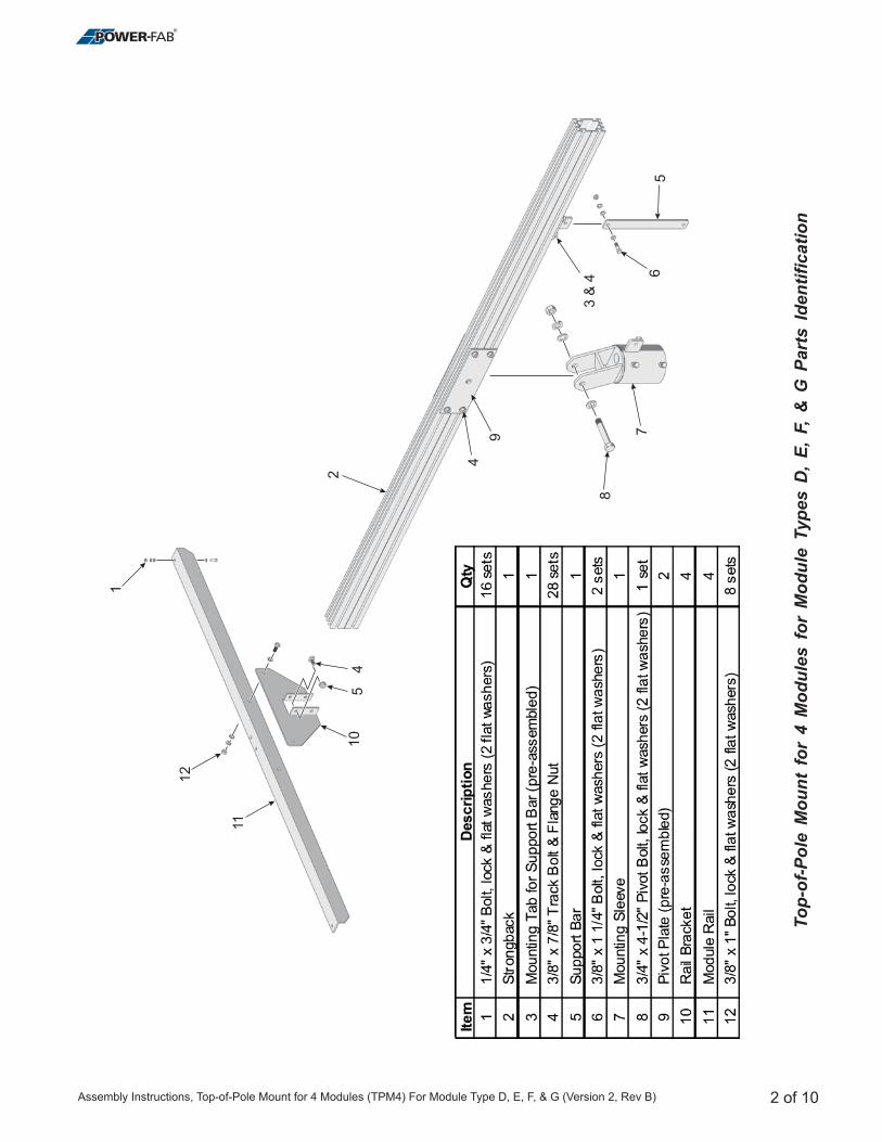
Top-of-Pole Mount for 4 Modules (TPM4)For Module Types D, E, F, & G
step-by-step
assembly and installation
D 31-33” 60-67”
E 38-40” 51-53”
F 38-42” 58-61”
G 37-42” 61-67”
ModuleType Width Length
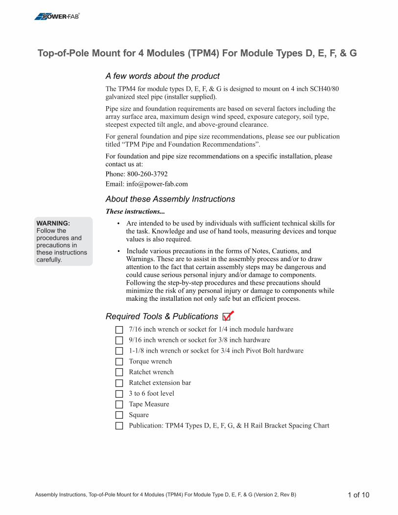
A few words about the product
About these Assembly Instructions
Required Tools & Publications
For foundation and pipe size recommendations on a specific installation, pleasecontact us at:
Phone: 800-260-3792
Email: [email protected]
These instructions...
�
�
Are intended to be used by individuals with sufficient technical skills forthe task. Knowledge and use of hand tools, measuring devices and torquevalues is also required.
Include various precautions in the forms of Notes, Cautions, andWarnings. These are to assist in the assembly process and/or to drawattention to the fact that certain assembly steps may be dangerous andcould cause serious personal injury and/or damage to components.Following the step-by-step procedures and these precautions shouldminimize the risk of any personal injury or damage to components whilemaking the installation not only safe but an efficient process.
The TPM4 for module types D, E, F, & G is designed to mount on 4 inch SCH40/80galvanized steel pipe (installer supplied).
Pipe size and foundation requirements are based on several factors including thearray surface area, maximum design wind speed, exposure category, soil type,steepest expected tilt angle, and above-ground clearance.
For general foundation and pipe size recommendations, please see our publicationtitled “TPM Pipe and Foundation Recommendations”.
7/16 inch wrench or socket for 1/4 inch module hardware
9/16 inch wrench or socket for 3/8 inch hardware
1-1/8 inch wrench or socket for 3/4 inch Pivot Bolt hardware
Torque wrench
Ratchet wrench
Ratchet extension bar
3 to 6 foot level
Tape Measure
Square
Publication: TPM4 Types D, E, F, G, & H Rail Bracket Spacing Chart
Top-of-Pole Mount for 4 Modules (TPM4) For Module Types D, E, F, & G
WARNING:Follow theprocedures andprecautions inthese instructionscarefully.
1 of 10Assembly Instructions, Top-of-Pole Mount for 4 Modules (TPM4) For Module Type D, E, F, & G (Version 2, Rev B)
2
11
12
56
8
79
51
0
4
3 &
4
4
1
To
p-o
f-P
ole
Mo
un
tfo
r4
Mo
du
les
for
Mo
du
leT
yp
es
D,
E,
F,
&G
Part
sId
en
tifi
cati
on
2 of 10Assembly Instructions, Top-of-Pole Mount for 4 Modules (TPM4) For Module Type D, E, F, & G (Version 2, Rev B)
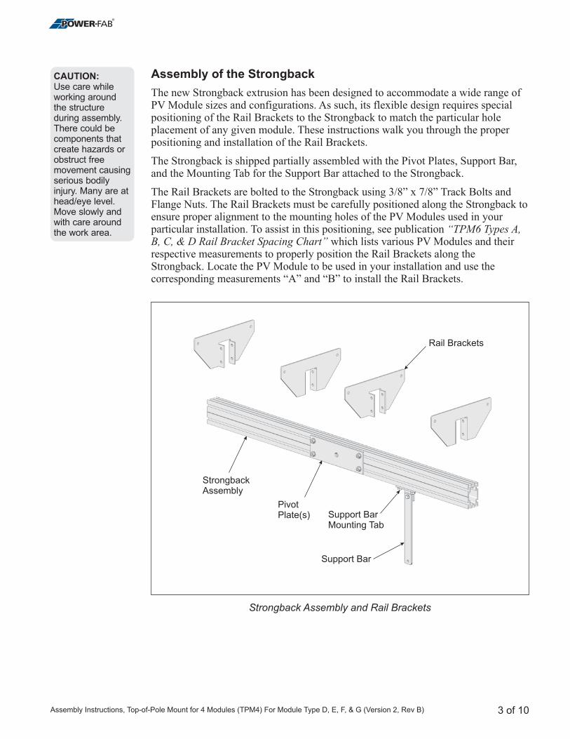
Assembly of the Strongback
The new Strongback extrusion has been designed to accommodate a wide range ofPV Module sizes and configurations. As such, its flexible design requires specialpositioning of the Rail Brackets to the Strongback to match the particular holeplacement of any given module. These instructions walk you through the properpositioning and installation of the Rail Brackets.
The Strongback is shipped partially assembled with the Pivot Plates, Support Bar,and the Mounting Tab for the Support Bar attached to the Strongback.
The Rail Brackets are bolted to the Strongback using 3/8” x 7/8” Track Bolts andFlange Nuts. The Rail Brackets must be carefully positioned along the Strongback toensure proper alignment to the mounting holes of the PV Modules used in yourparticular installation. To assist in this positioning, see publication
which lists various PV Modules and theirrespective measurements to properly position the Rail Brackets along theStrongback. Locate the PV Module to be used in your installation and use thecorresponding measurements “A” and “B” to install the Rail Brackets.
“TPM6 Types A,B, C, & D Rail Bracket Spacing Chart”
CAUTION:Use care whileworking aroundthe structureduring assembly.There could becomponents thatcreate hazards orobstruct freemovement causingserious bodilyinjury. Many are athead/eye level.Move slowly andwith care aroundthe work area.
3 of 10
Strongback Assembly and Rail Brackets
StrongbackAssembly
PivotPlate(s)
Support Bar
Support BarMounting Tab
Rail Brackets
Assembly Instructions, Top-of-Pole Mount for 4 Modules (TPM4) For Module Type D, E, F, & G (Version 2, Rev B)
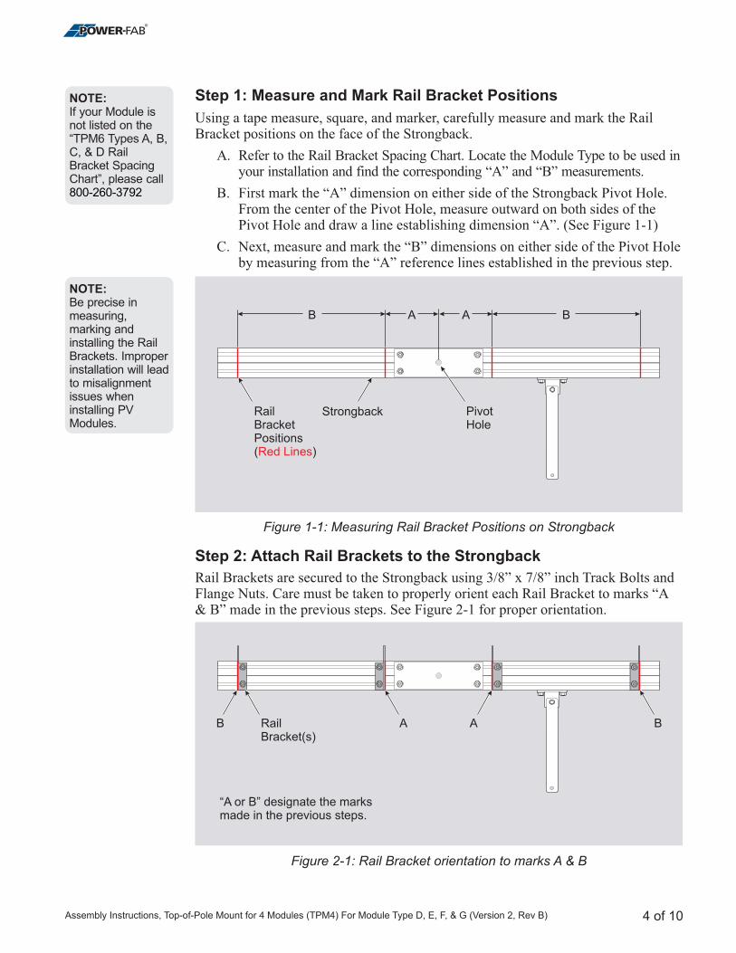
Step 1: Measure and Mark Rail Bracket Positions
Step 2: Attach Rail Brackets to the Strongback
Using a tape measure, square, and marker, carefully measure and mark the RailBracket positions on the face of the Strongback.
A. Refer to the Rail Bracket Spacing Chart. Locate the Module Type to be used inyour installation and find the corresponding “A” and “B” measurements.
B. First mark the “A” dimension on either side of the Strongback Pivot Hole.From the center of the Pivot Hole, measure outward on both sides of thePivot Hole and draw a line establishing dimension “A”. (See Figure 1-1)
C. Next, measure and mark the “B” dimensions on either side of the Pivot Holeby measuring from the “A” reference lines established in the previous step.
Rail Brackets are secured to the Strongback using 3/8” x 7/8” inch Track Bolts andFlange Nuts. Care must be taken to properly orient each Rail Bracket to marks “A& B” made in the previous steps. See Figure 2-1 for proper orientation.
4 of 10
Figure 1-1: Measuring Rail Bracket Positions on Strongback
B
“A or B” designate the marksmade in the previous steps.
BA ARailBracket(s)
Figure 2-1: Rail Bracket orientation to marks A & B
NOTE:Be precise inmeasuring,marking andinstalling the RailBrackets. Improperinstallation will leadto misalignmentissues wheninstalling PVModules.
NOTE:If your Module isnot listed on the“TPM6 Types A, B,C, & D RailBracket SpacingChart”, please call800-260-3792
StrongbackRailBracketPositions( )Red Lines
PivotHole
B BA A
Assembly Instructions, Top-of-Pole Mount for 4 Modules (TPM4) For Module Type D, E, F, & G (Version 2, Rev B)
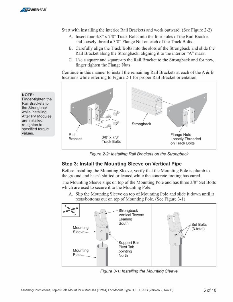
Figure 3-1: Installing the Mounting Sleeve
Strongback
RailBracket
Flange NutsLoosely Threadedon Track Bolts
3/8” x 7/8”Track Bolts
Figure 2-2: Installing Rail Brackets on the Strongback
5 of 10
Start with installing the interior Rail Brackets and work outward. (See Figure 2-2)
A. Insert four 3/8” x 7/8” Track Bolts into the four holes of the Rail Bracketand loosely thread a 3/8” Flange Nut on each of the Track Bolts.
B. Carefully align the Track Bolts into the slots of the Strongback and slide theRail Bracket along the Strongback, aligning it to the interior “A” mark.
C. Use a square and square-up the Rail Bracket to the Strongback and for now,finger tighten the Flange Nuts.
Continue in this manner to install the remaining Rail Brackets at each of the A & Blocations while referring to Figure 2-1 for proper Rail Bracket orientation.
Before installing the Mounting Sleeve, verify that the Mounting Pole is plumb tothe ground and hasn't shifted or leaned while the concrete footing has cured.
The Mounting Sleeve slips on top of the Mounting Pole and has three 3/8” Set Boltswhich are used to secure it to the Mounting Pole.
A. Slip the Mounting Sleeve on top of Mounting Pole and slide it down until itrests/bottoms out on top of Mounting Pole. (See Figure 3-1)
Step 3: Install the Mounting Sleeve on Vertical Pipe
NOTE:Finger-tighten theRail Brackets tothe Strongbackwhile installing.After PV Modulesare installedre-tighten tospecified torquevalues.
NE
WS
MountingSleeve
StrongbackVertical TowersLeaningSouth
Support BarPivot TabpointingNorth
MountingPole
Set Bolts(3-total)
Assembly Instructions, Top-of-Pole Mount for 4 Modules (TPM4) For Module Type D, E, F, & G (Version 2, Rev B)
B. Rotate the Mounting Sleeve so that the Support Bar Pivot Tab is pointingnorth and the Strongback Vertical Towers are leaning south.
C. Secure the Mounting Sleeve by tightening the three 3/8” Set Bolts.
/8”
For safety and ease of assembly, position the Strongback at 0-degrees or level to theground. Follow these steps to level and secure the Strongback. This is a two personactivity, with one person supporting the Strongback while the second adjusts andsecures the Strongback with the Support Bar.
E. First, loosen the four 3/8” Flange Nuts securing the Support Bar MountingTab to the Strongback. (See Figure 4-2)
Torqueeach Set Bolt to 32-34 ft.-lbs.
Step 4: Installing the Strongback on the Mounting Sleeve
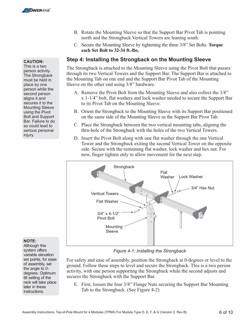
The Strongback is attached to the Mounting Sleeve using the Pivot Bolt that passesthrough its two Vertical Towers and the Support Bar. The Support Bar is attached tothe Mounting Tab on one end and the Support Bar Pivot Tab of the MountingSleeve on the other end using 3/8” hardware.
A. Remove the Pivot Bolt from the Mounting Sleeve and also collect the 3x 1-1/4” bolt, flat washers and lock washer needed to secure the Support Barto its Pivot Tab on the Mounting Sleeve.
B. Orient the Strongback to the Mounting Sleeve with its Support Bar positionedon the same side of the Mounting Sleeve as the Support Bar Pivot Tab.
C. Place the Strongback between the two vertical mounting tabs, aligning thethru-hole of the Strongback with the holes of the two Vertical Towers.
D. Insert the Pivot Bolt along with one flat washer through the one VerticalTower and the Strongback exiting the second Vertical Tower on the oppositeside. Secure with the remaining flat washer, lock washer and hex nut. Fornow, finger tighten only to allow movement for the next step.
6 of 10
Figure 4-1: Installing the Strongback
NOTE:Although thissystem offersvariable elevationset points, for easeof assembly, setthe angle to 0-degrees. Optimumtilt setting of therack will take placelater in theseinstructions.
CAUTION:This is a twoperson activity.The Strongbackmust be held inplace by oneperson while thesecond personaligns it andsecures it to theMounting Sleeveusing the PivotBolt and SupportBar. Failure to doso could lead toserious personalinjury.
Strongback
3/4Bolt
” x 4-1/2”Pivot
Flat Washer
Vertical Towers
Lock Washer
3/4” Hex Nut
MountingSleeve
FlatWasher
Assembly Instructions, Top-of-Pole Mount for 4 Modules (TPM4) For Module Type D, E, F, & G (Version 2, Rev B)
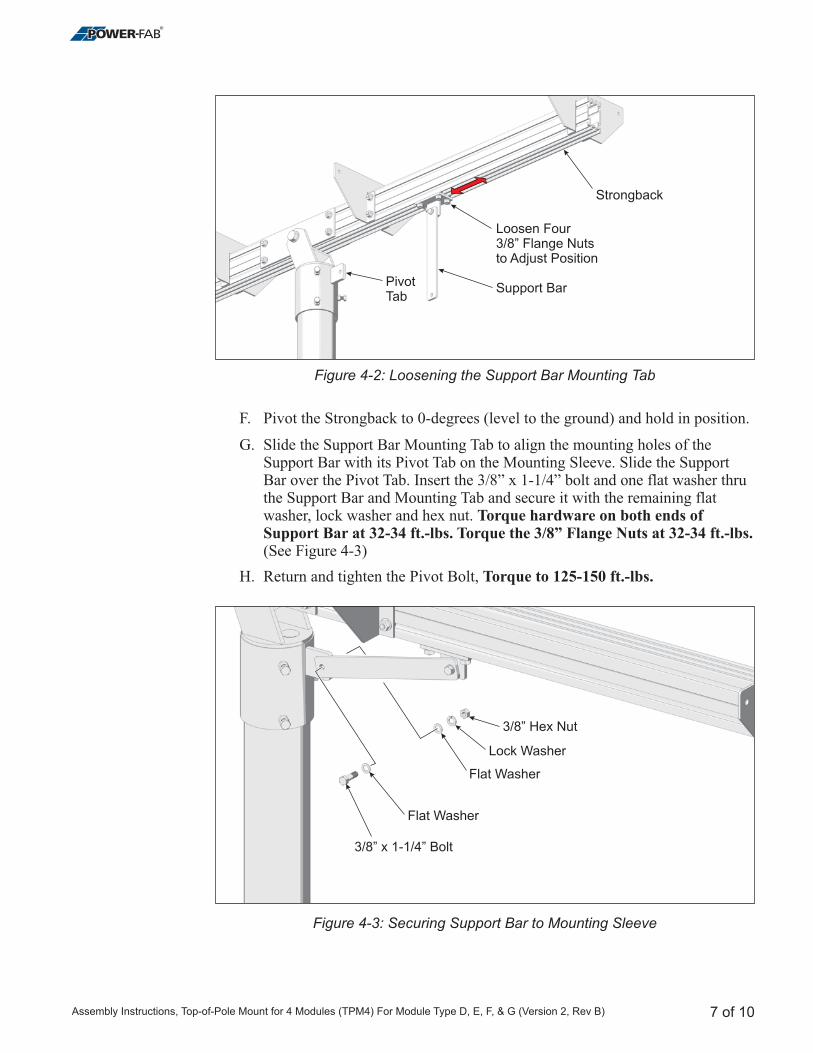
F. Pivot the Strongback to 0-degrees (level to the ground) and hold in position.
G. Slide the Support Bar Mounting Tab to align the mounting holes of theSupport Bar with its Pivot Tab on the Mounting Sleeve. Slide the SupportBar over the Pivot Tab. Insert the 3/8” x 1-1/4” bolt and one flat washer thruthe Support Bar and Mounting Tab and secure it with the remaining flatwasher, lock washer and hex nut.
(See Figure 4-3)
H. Return and tighten
Torque hardware on both ends ofSupport Bar at 32-34 ft.-lbs. Torque the 3/8” Flange Nuts at 32-34 ft.-lbs.
Torque to 125-150 ft.-lbs.the Pivot Bolt,
7 of 10
Figure 4-2: Loosening the Support Bar Mounting Tab
Strongback
Support BarPivotTab
Loosen Four3/8” Flange Nutsto Adjust Position
Figure 4-3: Securing Support Bar to Mounting Sleeve
3/8” Boltx 1-1/4”
Flat Washer
Flat Washer
Lock Washer
3/8” Hex Nut
Assembly Instructions, Top-of-Pole Mount for 4 Modules (TPM4) For Module Type D, E, F, & G (Version 2, Rev B)
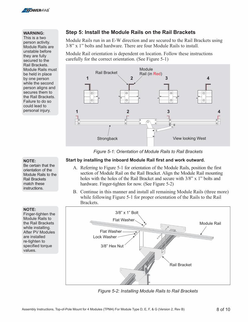
Step 5: Install the Module Rails on the Rail Brackets
Module Rails run in an E-W direction and are secured to the Rail Brackets using3/8” x 1” bolts and hardware. There are four Module Rails to install.
Module Rail orientation is dependent on location. Follow these instructionscarefully for the correct orientation. (See Figure 5-1)
A. Referring to Figure 5-1 for orientation of the Module Rails, position the firstsection of Module Rail on the Rail Bracket. Align the Module Rail mountingholes with the holes of the Rail Bracket and secure with 3/8” x 1” bolts andhardware. Finger-tighten for now. (See Figure 5-2)
B. Continue in this manner and install all remaining Module Rails (three more)while following Figure 5-1 for proper orientation of the Rails to the RailBrackets.
Start by installing the inboard Module Rail first and work outward.
8 of 10
WARNING:This is a twoperson activity.Module Rails areunstable beforethey are fullysecured to theRail Brackets.Module Rails mustbe held in placeby one personwhile the secondperson aligns andsecures them tothe Rail Brackets.Failure to do socould lead topersonal injury.
Figure 5-1: Orientation of Module Rails to Rail Brackets
Figure 5-2: Installing Module Rails to Rail Brackets
NOTE:Be certain that theorientation of theModule Rails to theRail Bracketsmatch theseinstructions.
NOTE:Finger-tighten theModule Rails tothe Rail Bracketswhile installing.After PV Modulesare installedre-tighten tospecified torquevalues.
1 2 3 4
1 2 3 4
ModuleRail (in )Red
Strongback View looking West
Rail Bracket
3/8” Boltx 1”
Flat Washer
Rail Bracket
Module Rail
Flat Washer
Lock Washer
3/8” Hex Nut
Assembly Instructions, Top-of-Pole Mount for 4 Modules (TPM4) For Module Type D, E, F, & G (Version 2, Rev B)
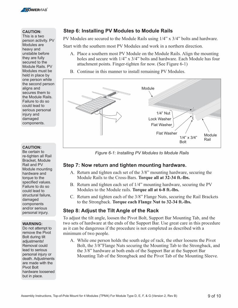
Step 6: Installing PV Modules to Module Rails
Step 7: Now return and tighten mounting hardware.
Step 8: Adjust the Tilt Angle of the Rack
PV Modules are secured to the Module Rails using 1/4” x 3/4” bolts and hardware.
Start with the southern most PV Modules and work in a northern direction.
A. Place a southern most PV Module on the Module Rails. Align the mountingholes and secure with 1/4” x 3/4” bolts and hardware. Each Module has fourattachment points. Finger-tighten for now. (See Figure 6-1)
B. Continue in this manner to install remaining PV Modules.
A. Return and tighten each set of the 3/8” mounting hardware, securing theModule Rails to the Cross-Bars.
B. Return and tighten each set of 1/4” mounting hardware, securing the PVModules to the Module rails.
To adjust the tilt angle, loosen the Pivot Bolt, Support Bar Mounting Tab, and thetwo sets of hardware at the ends of the Support Bar. Use great care in this procedureas it can be dangerous if the procedure is not completed as described with aminimum of two people.
A. While one person holds the south edge of rack, the other loosens the PivotBolt, the 3/8”Flange Nuts securing the Mounting Tab to the Strongback, andthe 3/8” hardware at both ends of the Support Bar at the Support BarMounting Tab of the Strongback and the Pivot Tab of the Mounting Sleeve.
Torque all at 32-34 ft.-lbs.
Torque all at 6-8 ft.-lbs.
C. Return and tighten each of the 3/8” Flange Nuts, securing the Rail Bracketsto the Strongback. Torque each Flange Nut to 32-34 ft.-lbs.
9 of 10
Figure 6-1: Installing PV Modules to Module Rails
CAUTION:This is a twoperson activity. PVModules areheavy andunstable beforethey are fullysecured to theModule Rails. PVModules must beheld in place byone person whilethe second personaligns andsecures them tothe Module Rails.Failure to do socould lead toserious personalinjury anddamagedcomponents.
CAUTION:Be certain tore-tighten all RailBracket, ModuleRail and PVModule mountinghardware andtorque to thespecified values.Failure to do socould lead tostructural failure,damagedcomponentsand/or seriouspersonal injury.
WARNING:Do not attempt toremove the PivotBolt during tiltadjustments!Removal couldlead to seriouspersonal injury ordeath. Adjustmentsare made with thePivot Bolthardware loosenedbut in place.
1/4” x 3/4”Bolt
Lock Washer
Flat Washer
Flat Washer
1/4” Nut
Module
ModuleRail
Assembly Instructions, Top-of-Pole Mount for 4 Modules (TPM4) For Module Type D, E, F, & G (Version 2, Rev B)
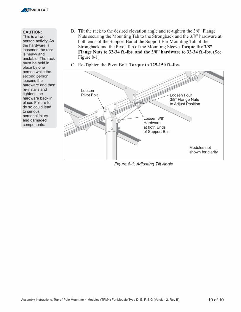
B. Tilt the rack to the desired elevation angle and re-tighten the
(SeeFigure 8-1)
C. Re-Tighten the Pivot Bolt.
3/8” FlangeNuts securing the Mounting Tab to the Strongback and the 3/8” hardware atboth ends of the Support Bar at the Support Bar Mounting Tab of theStrongback and the Pivot Tab of the Mounting Sleeve Torque the 3/8”Flange Nuts to 32-34 ft.-lbs. and the 3/8” hardware to 32-34 ft.-lbs.
Torque to 125-150 ft.-lbs.
10 of 10
Figure 8-1: Adjusting Tilt Angle
CAUTION:This is a twoperson activity. Asthe hardware isloosened the rackis heavy andunstable. The rackmust be held inplace by oneperson while thesecond personloosens thehardware and thenre-installs andtightens thehardware back inplace. Failure todo so could leadto seriouspersonal injuryand damagedcomponents.
Loosen Four3/8” Flange Nutsto Adjust Position
Loosen 3/8”Hardwareat both Endsof Support Bar
LoosenPivot Bolt
Modules notshown for clarity
Assembly Instructions, Top-of-Pole Mount for 4 Modules (TPM4) For Module Type D, E, F, & G (Version 2, Rev B)

4000-B Vassar Drive NE
Albuquerque, New Mexico 87107
USA
Telephone: 800.260.3792
Fax: 505.889.3548
Web Site: www.DPWSolar.com
E-mail: [email protected]
© 2011 Preformed Line Products
PCN 062811-10
Version 2, Rev B
For product or purchasing inquiries contact:
www.ecodirect.com