Embed Size (px)
Citation preview

3 5 G R E E N S T R E E T P O B O X 6 5 3 M A L D E N ,
92 with AS-Interface Inst Manual October 16, 2003
AS-InteInstallation M
ASAHI / AMERICA, Inc.
Thermoplastic Valves and Piping Systems
®
M A . 0 2 1 4 8
Revison A Page 1 of 8
rface anual

Electric Installation
AS-I Operation
T he internally mounted sensor has two proximity switches located in a compact sealed housing which are triggered by the standard cams mounted on the actuator shaft. As the actuator cycles, the cams align with the sensor and
activate the proximity switch. When the valve is open, the top cam is directly in front of the sensor and an open valve status is shown. When the valve is closed, the bottom cam is directly in front of the sensor and a close status is shown. This sensor is wired to one side of the internally mounted AS-I communications PCB. The other side of the communications PCB accepts the actuator supply voltage (115 VAC, 230 VAC, etc). The AS-I master communicates with the PCB; and when commanded by the master, relays inside the PCB change states and cycles the actuator.
AS-I Installation
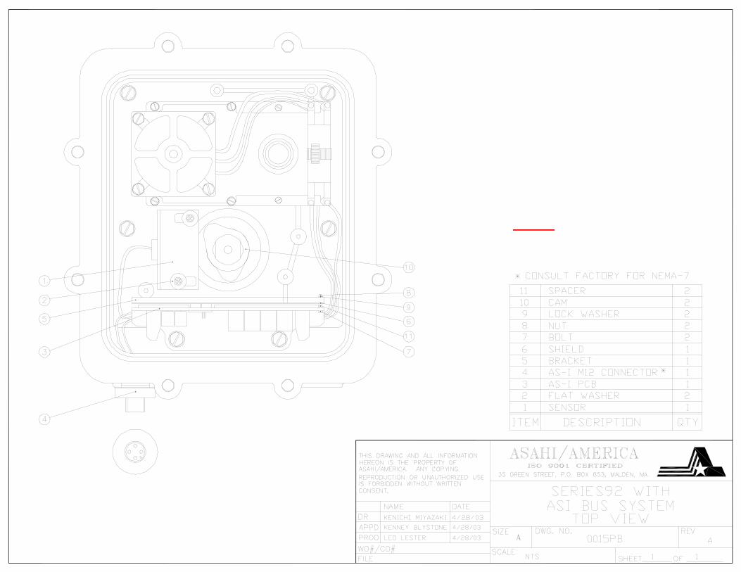
Reference drawing # 289S92 for actuator internal modifications and drawing #’s 0015PB and 0016PB for AS-I accessory installation
D isconnect wiring from terminal strip #24 and limit switches #25 (capacitor wiring will be modified later). Now remove terminal strip #24 and switches #25, as they are not required (do not discard screws). Install sensor and
spacer to limit switch posts using limit switch screws and supplied washers (make sure gap between sensor and cam is approximately 1/16”). Install PCB bracket onto base plate using screws from terminal strip (make sure that bracket screws and base plate screws are facing the conduits). Mount PCB and shield to bracket using supplied screws, nuts, and spacers; making sure NOT to over-tighten as PCB damage will occur. Install M12 conduit connector in the left side conduit for wiring to PCB. Remove connectors from capacitor wires where they connected to the limit switch and terminate to PCB as shown on dwg #0016PB. Continue terminating sensor and conduit (as per dwg# 0016PB); installation of components is complete.
AS-I Maintenance
T here is no maintenance to be performed for the AS-I components. Tin
have to be
he Series 92 electric actuators are manufactured with lubricating grease the gear case and gearbox. In most cases, this lubricant should never replenished; however if deemed necessary, we recommend using
Aeroshell Grease #17, mfg. by Shell Oil Co. Consult our technical department before replenishing lubricant.
92 with AS-Interface Installation Manual Page 2 of 8

In outdoor or wet locations keep top and bottom seals coated with a silicone-based grease. CAUTION:
Before any maintenance is performed, and to reduce the chance of electrical shock, NEVER remove actuator cover while circuits are live.
Spare Parts
The following should be kept on hand as spare parts.
1 --- Capacitor (Part #27 or #28)
Sensor Specifications
Electrical Design AC / DC Output Normally Open Operating Voltage 20-140 AC / 10-140 DC Current Rating (Continuous) 200 mA Minimum Load Current 5mA Short-circuit Protection — Reverse Polarity Protection — Overload Protection — Leakage Current <.8mA Real Sensing Range .16 +/- 10% Operating Distance 0 - .13 in
Function Display Switching Status LED
2 x Red
Operating Temperature 0º F - 176º F Protection IP67 Housing Material Pocan; PC Connection PVC Cable/6ft
92 with AS-Interface Inst Manual October 16, 2003 Revison A Page 3 of 8

Communication PCB Specifications
Reverse Polarity Protection AS-I Power Only Sensor Supply Short Circuit Protected
Yes (current limit at 200mA) *
Current Consumption <130 mA with Above Sensor AS-I Voltage Range 26.5…31.6 VDC Indication of AS-I Power LED (Green) Output Relay Output (Supply) Voltage ?
Maximum Current Load Per Output ?
Switching Status 4 LEDs (Yellow) Operating Temperature 0º F - 125º F * A short circuit at the output supply is not signaled to the AS-I Master
Series 92 Description
A sahi/America Series 92 reversing electric actuators feature capacitor run motors, permanently lubricated gear train, and hardened steel spur gears. These units can provide from 400 in-lbs up to 2000 in-lbs. of output
torque. The Series 92 models feature a Nema-4 (7)* enclosure as a standard and are available in 115VAC, 220VAC, 12VDC, 24VDC, 12VAC, and 24VAC voltages. *Consult factory for NEMA 7 AS-Interface models are equipped with integral thermal overload protection with automatic reset (AC models), an independently adjustable limit switch sensor, declutchable manual override, position indicating beacon, baked powder epoxy coating, stainless steel trim and an ISO bolt circle.
92 with AS-Interface Inst Manual October 16, 2003 Revison A Page 4 of 8

Series 92 Installation
Reference drawing# 289S92
1. To gain access to terminal strip it is necessary to remove manual override knob (Part #18 for Models S-92, A92, B92 or Hand wheel Part #18A for Model C-92) by loosening slotted setscrew (Part #39). Remove cam (Part #51) by loosening 2 set screws. Remove 2 cover screws, the remaining 6 cover screws are packaged inside the actuator.
2. Install conduit fitting (1/2" NPT) to actuator base. Note: Proper conduit fitting must be used to maintain enclosure rating (weatherproof, explosion proof or combination weather proof/explosion proof). See actuator serial# tag located on housing for NEMA rating.
3. Make electrical connections to terminal strip as shown on wiring schematic #0016PB (per various electrical codes there is a green screw on the actuator base plate for grounding purposes). Terminals are suitable for up to #14 AWG wire. All units are completely calibrated prior to shipment. No internal adjustments should be required.
4. We recommend sealing conduit openings on units installed outdoors or exposed to large temperature swings (15ºF or more). We also recommend the heater option in these applications.
5. Replace actuator cover, and gasket if removed. Install 8 cap screws supplied and tighten securely. For outdoor or wet locations it is recommended prior to replacing the cover that the top shaft seal be cleaned and coated with silicone grease. Also clean shaft and lightly coat seal area of shaft with silicone grease. Unit is now ready for operation.
Manual Override Operation
P ull up the declutching knob (Part #18) and apply a 5/8" open end wrench to exposed flats and rotate within labeled limits as indicated by arrows for Models S92, A92, B92. For Model C92 push down on hand wheel (Part #18A) and
rotate within labeled limits
To re-engage simply rotate actuator shaft in the opposite direction until declutching knob drops back down into position (Models S92, A92, B92). For Model C92 rotate hand wheel until it moves up and re-engages.
CAUTION: The manual override should only be used when there is no power applied to actuator. When power is restored the actuator will automatically resume normal operation
92 with AS-Interface Inst Manual October 16, 2003 Revison A Page 5 of 8

Electrical Requirements
Mounting Instructions
P osition the valve and the actuator to corresponding positions (either OPEN or CLOSED). The flats on the actuator shaft and the indicator should now indicate valve position.
Ball Valves
1. Multi Port Ball Valves: Reference Drawing #0110BV for 1/2” - 2”
Install plate #8 to actuator #2 using screws #7 (1-1/2” and 2” only). Mount saddle #5 onto valve #1, (Saddle is an interference fit over neck of valve press down tight), then tighten setscrews #3 to secure in place. Insert coupling #6 onto stem of valve #1 and bolt actuator #2 onto assembly tightening bolts #4 evenly.
2. Multi Port Ball Valves: Reference Drawing #0111BV for 2-1/2” – 4”
Install plate #6 to actuator #2 using screws #8. Mount saddle #5 onto valve #1, (Saddle is an interference fit over neck of valve press down tight must also be solvent cemented to valve body), then tighten setscrews #3 to secure in place. Insert coupling #7 onto stem of valve #1 and bolt actuator #2 onto assembly tightening bolts #4 evenly.
Note: Due to the torque required on sizes 3” and 4”, we recommend that saddle #5 be solvent cemented to valve as well as using set screws #3.
3. Type 21 Ball Valves: Reference Drawing #0107BV for 1/2"-2"
92 with AS-Interface Inst Manual October 16, 2003 Revison A Page 6 of 8

Install mounting bracket #3 to actuator #2 using bolts #8 and washers #9. Insert coupling #4 on stem of valve #1 and then bolt valve #1 to mounting bracket #3 using bolts #5, nuts #6, and washers #7.
Note: All bolts should be snug and not excessively over tightened.
4. Type 21 Ball Valves: Reference Drawing #0113BV for 2-1/2” - 4"
Install mounting bracket #3 to actuator #2 using bolts #8 and washers #9. Insert coupling #4 on stem of valve #1 and then bolt valve #1 to mounting bracket #3 using bolts #5, nuts #6, and washers #7.
Note: All bolts should be snug and not excessively over tightened.
Butterfly Valves
1. Type 56 Butterfly Valves: Reference Drawing # 0204BF for sizes 1-1/2” thru 6”
All 1-1/2” – 6” Type 56 butterfly valves as a standard feature conform to an ISO 5211/I-5211/II-DIN-3.337 specification standard. No Specially machined stem or valve body drilling required. Remove handle (remove handle cap & hex head bolt) to expose throttle plate screws. Remove throttle plate and retaining washer to expose existing (F) series bolt pattern.
CAUTION: If valve is in line, system must be shut down and have no line pressure before removing throttle plate and retaining washer.
Install mounting bracket #3 to actuator #2 using bolts #8 and washers #9. Insert coupling #4 on stem of valve #1 and then bolt valve #1 to mounting bracket #3 using bolts #5, nuts #6, and washers #7. Keeping in mind line scribed in top of valve stem indicates disc orientation before mounting and actuator flats indicate disc orientation after mounting.
2. Type 56 Butterfly Valves: Reference Drawing # 0168BF for size 8”
All 8” Type 56 butterfly valves as a standard feature conform to an ISO 5211/I-5211/II-DIN-3.337 specification standard. No Specially machined stem or valve body drilling required. Remove handle (remove handle cap & hex head bolt) to expose throttle plate screws. Remove throttle plate and retaining washer (or gear-operator) to expose existing (F) series bolt pattern.
CAUTION: If valve is in line, system must be shut down and have no line pressure before removing throttle plate and retaining washer or gear-operator.
Install mounting bracket #2 to actuator #10 using bolts #7 and washers #8. Insert coupling #9 on stem of valve #1 and then bolt valve #1 to mounting bracket #2 using
92 with AS-Interface Inst Manual October 16, 2003 Revison A Page 7 of 8

bolts #3, nuts #6, and washers #4 & 5. Keeping in mind line scribed in top of valve stem indicates disc orientation before mounting and actuator flats indicate disc orientation after mounting.
CAUTION: If mounted unit is installed other than straight up, the actuator should be supported independently to prevent side loading and loosening up of fasteners.
NOTE: When ordering replacement motor parts, and/or options, model # and voltage must be specified.
Attachments: 10 drawings: 0016PB, 0015PB, 0168BF, 0130BV, 0200BF, 0107BV, 0110BV, 0111BV, 0113BV, 289S92
Asahi/America 19 Green Street Malden, Ma. 02148
Phone: 800-343-3618 Fax: 800-426-7058
Internet: http://www.asahi-america.com
92 with AS-Interface Inst Manual October 16, 2003 Revison A Page 8 of 8