Embed Size (px)
Citation preview
arista.com
White Paper
Arista 7280R3 Switch Architecture (‘A day in the life of a packet’)
The Arista Networks 7280R3 Series are purpose built high performance fixed configuration fixed form factor Universal
Leaf switches and routers with a deep buffer, virtual output queue architecture combined with rich features. The
7280R3 series are the latest in the evolution of fixed systems that commenced in 2010 with the first generation systems
delivering 1G and 10G as a deep buffer fixed leaf based on the Broadcom Petra silicon. Through successive incremental
bandwidth and feature enhancements the 7280R3 series supports a wide variety of systems options and interfaces
including 25G, 100G and 400G, based on the Broadcom Jericho2 silicon.
Figure 2: Arista 7280R Series Platform Generations
Figure 1: Arista 7280R3 Universal Leaf Systems

arista.comarista.com
White Paper
The 7280R3 series addresses the demands of modern networking and rich multimedia content delivery, requiring a
lossless forwarding solution. They are ideal for Universal Cloud Networks, where deep buffers and wire speed L2 and L3
forwarding are combined with advanced features for network virtualization, open and programmable monitoring and
network analysis, resiliency and architectural flexibility.
Additionally, the deep packet buffers and 7280R3 series support for highly scalable IPv4 and IPv6 tables allow for a wide
range of open networking solutions, including Cloud WAN aggregation, Service Provider NFV, Internet Peering and
Peering Exchanges, Overlay Networks, Content Delivery and evolution of the network edge.
Since its introduction the Arista 7280 series has delivered continuous improvements in performance and density
with each generation, with significant increases in features and functionality, with investment protection of existing
deployments. Evolving from a best-in-class Cloud-scale switching to an Internet-scale, service provider routing
platform. This white paper provides an overview of the architecture of the Arista 7280R3 Universal Leaf platform.
Arista 7280R3: Overview The Arista 7280R3 Universal Leaf platform represents the evolution of the 7280R family of fixed form factor switches, and are available in a choice of 1U and 2U systems. The 7280R3 has a number of differentiators compared to other fixed configuration systems. The major advantages come from the proven VoQ and deep buffer architecture combined with the rich EOS feature set and a programmable pipeline.
• Standards-based high density 100G and 400G switch ideal for future proof designs and high bandwidth needs, such as in Internet Exchanges, High Performance Storage or Content Delivery Networks (CDNs).
• Segment Routing and EVPN with flexible options for underlay and overlay topologies.
• Ultra-deep buffers in a fixed form factor makes for an ideal spine switch where lossless performance and in-cast problems are expected, such as in big data analytics, search and IP storage.
• Directly connected 25GbE, 40GbE and 50GbE attached storage systems, requiring high performance and predictable latency.
• Flexible support for 100G and 400G with wide selection of optics and cables including 400G OSFP and QSFP-DD form factors.
• Comprehensive L2 and L3 feature set for open multi-vendor networks with no proprietary lock-in.
• Scalable forwarding table resources allow deployment flexibility in both large L2 and L3 environments with any-workload suitability.
• Accelerated sFlow and IPFIX for network forensics.
• Streaming network state for advanced analytics with Arista CloudVision®.
• Network–wide virtualization platform for next generation cloud bursting with wire-speed VXLAN routing.
• Hardware-assisted PTP enables accurate timing solutions across Ethernet-based networks, without costly investment in separate timing networks.
• Unique monitoring and provisioning features – LANZ, DANZ, AEM, IEEE 1588 PTP, ZTP, VM Tracer, VXLAN, and eAPI.
• Programmable packet processor for advanced features and flexible profiles enabling different use cases including peering
arista.comarista.com
White Paper
and DCI.
• NEBS compliance and DC power supplies designed for service provider environments.
• MACsec encryption for simple, reliable and scalable datacenter interconnect and for securing links between tiers in leaf and spine datacenter designs.
The 7280R3 platform is designed for lossless behavior, in environments where large scale routing, VXLAN Routing, DANZ and enhanced LANZ are needed. It is ideal for networks where 100G and 400G uplinks are planned, for investment protection, and any place where system scalability is a concern. In addition, all members of the 7280R3 Series support full internet scale peering.
At a system level the Arista 7280R3 scales to 96 x 100G in 2 RU and 24 x 400G in 1RU providing industry-leading performance and density without compromising on features, functionality or investment protection.
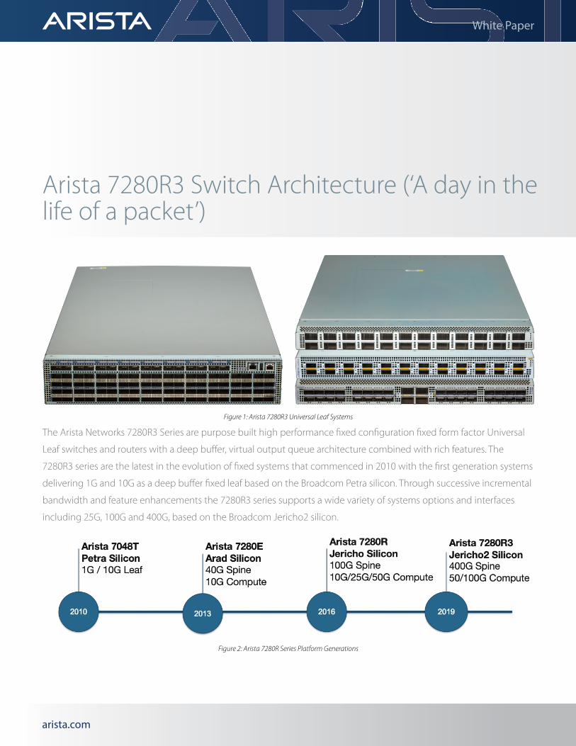
System SpecificationsThe tables below provide system specifications for all the 7280R3 platforms.
Table 1: Arista 7280R3 and 7280R3K Port Combinations and Forwarding Metrics
7280R3 Series 7280PR3-24 and
7280PR3K-24
7280DR3-24 and
7280DR3K-24
7280CR3-32P4 and
7280CR3K-32P4
7280CR3-32D4 and
7280CR3K-32D4
7280CR3-96 and
7280CR3K-96
Max 400GbE Ports 24 24 4 4
Max 100GbE Ports 96 96 48 48 96
Max 50GbE Ports 192 192 96 96 192
Max 40GbE Ports 24 24 36 36 96
Max 25GbE Ports 192 192 96 96 192
Max 10GbE Ports 192 192 96 96 192
L2/3 Throughput 9.6Tbps 9.6Tbps 4.8 Tbps 4.8 Tbps 9.6Tbps
L2/3 PPS 4 Bpps 4 Bpps 2 Bpps 2 Bpps 4 Bpps
Latency From 3.8us From 3.8us From 3.8us From 3.8us From 3.8us
Total System Buffer 16GB 16GB 8GB 8GB 16GB
Rack Units 1 1 1 1 2
Airflow F/R F/R F/R and R/F F/R and R/F F/R
Arista 7280R - Router Table Scale, Features and Functionality In addition to increasing system capacity and performance, forwarding table sizes have continued to grow. Arista’s innovative FlexRoute™ Engine enables more than a million IPv4 and IPv6 route prefixes in hardware, significantly beyond what merchant silicon enables natively. Arista EOS NetDB™ evolution of SysDB allows for increased scale and performance with industry leading routing convergence, creating the first fixed switch system to truly be called a router. Extensions to FlexRoute for switches with larger on-chip tables increases the capability to over 2M routes, of both IPv4 and IPv6, with the ability to contain multiple full-route table copies and ensure many years of investment protection.
The table below shows the key scale metrics of the 7280R, 7280R2, 7280R2K, 7280R3 and 7280R3K Series.

arista.comarista.com
White Paper
1 Represents a balanced profile for the partitioning of the MDB
Arista 7280R3 - Cloud Scale And FeaturesEach iteration of the packet processor silicon in the Arista 7280 Series – from the first-generation in 2010 (Petra / 7048) to the latest (Jericho2 / 7280R3) has been riding Moore’s Law. This observation, that on average, there will be two times more transistors available every two years has held true for decades. The network silicon within the Arista 7048/7280 Series has used those additional transistors to more than double performance and density at each generation, from 80Gbps per packet processor (8 x 10G interfaces) to 4.8Tbps (12 x 400G interfaces).
In addition to delivering increased port density and performance, forwarding table sizes have continued to increase. The 7280R3 family provides operators with Internet routing scale through Arista’s innovative FlexRoute Engine, extending forwarding table capacity beyond what merchant silicon enables natively. With the 7280R3 this innovation continues. The 7280R3-series introduces the Modular Database (MDB) to enable the flexible allocation of forwarding resources to accommodate a wide range of network deployment roles.
The MDB provides a common database of forwarding and lookup resources to the ingress and egress stages in the 7280R3 platform. These resources are allocated using forwarding profiles that ensure the optimal allocation to different tables for a wide range of networking use-cases. The L3 optimized profile expands the routing and next-hop tables to address large scale networks where route table capacity is required, while the balanced profile is suited for leaf and spine datacenter applications.
Table 2: Arista 7280R Key L2, L3 Scale Metrics
7280R Series (Jericho)
7280R2 Series (Jericho+)
7280R2K Series (Jericho+)
7280R31 Series (Jericho2)
7280R3K1 Series (Jericho2)
MAC Table Size 768K 768K 768K 736K 448K
IPv4 Host Routes 768K 768K 768K 896K 1.4M
IPv4 Route Prefixes 1M+ Up to 1.3M 2M+ 704K 1.2M
IPv6 Host Routes 768K 768K 768K 224K 368K
IPv6 Route Prefixes 928K Up to 1M 1.4M+ 235K 411K
Multicast Routes Up to 768K Up to 768K Up to 768K 448K 448K
LAG Groups 1152 1152 1152 1152 1152
LAG Members 64 Ports 64 Ports 64 Ports 128 Ports 128 Ports
ECMP Fanout 128-way 128-way 128-way 256-way 256-way
Figure 3: MDB enables a flexible range of deployment profiles.

arista.comarista.com
White Paper
The fungible nature of the resources within the MDB ensure that operators have the flexibility they need to standardize on a common platform across a wide range of roles with the confidence that the specific resource requirements can be allocated according to the needs of any given role. There is no need to have a separate platform for core network roles and edge roles in today’s service provider networks. This enables cloud and service providers to streamline their deployments, simplify sparing and consolidate testing.
AirflowThe 7280R3 Series offers a choice of airflow direction (front-to-rear or rear-to-front). Power and fan modules are color-coded to show the airflow direction through the switch, making it easy to identify how the switch should be installed in a rack where Hot/Cold aisle separation is required.
Red handles shown below denote hot aisle placement with Airflow exit from the switch. Blue handles denote cold aisle placement with Airflow intake to the switch.
Arista 7280R3 Universal Leaf System Architecture All 7280R3 Series switches share a common system design built around a high performance x86 CPU for the control plane. The CPU is connected to system memory, internal flash, SSD, bootflash, power supplies, fans, management I/O and peripherals, as shown below.
Figure 4: 7280R3 Series 1RU & 2RU Switch Chassis Rear View
Figure 5: Arista 7280R3 High Level System Architecture

arista.comarista.com
White Paper
The Arista 7280R3 switches were designed for continuous operations with system wide monitoring of both hardware and software components, simple serviceability and provisioning to prevent single points of failure.
Key high availability features include:
• 1+1 hot-swappable power supplies and hot-swap fans provide dynamic temperature control combined with N+1 redundancy.
• Color coded PSU’s and fans that deliver platinum level power efficiency.
• Live software patching.
• Self healing software with Stateful Fault Repair (SFR).
• Smart System Upgrade (SSU).
The x86 CPU is also connected over PCIe to the 7280R3 Packet Processor(s) that run all the data plane forwarding and have all the directly connected front panel ports.
All stages associated with packet forwarding are performed in an integrated system on chip (SoC) packet processor. The Jericho2 packet processor provides both the ingress and egress packet forwarding pipeline stages for packets that arrive or are destined to ports serviced by that packet processor. Each packet processor can perform local switching for traffic between ports on the same packet processor.
Port IdentificationThe 40G, 100G and 400G QSFP type transceivers are the same physical size and can be inserted into any QSFP based ports. It’s important that switches indicate the port capabilities on the front panel so that an engineer installing transceivers inserts them into the correct port types.
The figure below shows QSFP100 and QSFP-DD ports. The 100G QSFP ports are highlighted with a lilac line to identify they are QSFP100 capable; these ports will support either QSFP+ (40G) or QSFP100 (100G) transceivers. The 400G capable QSFP-DD ports in the center are highlighted in orange. The OSFP 400G ports are marked similarly.
Figure 6: Arista 7280CR3-32P4 Switch Architecture
Figure 7: QSFP 100 & QSFP-DD Ports
arista.comarista.com
White Paper
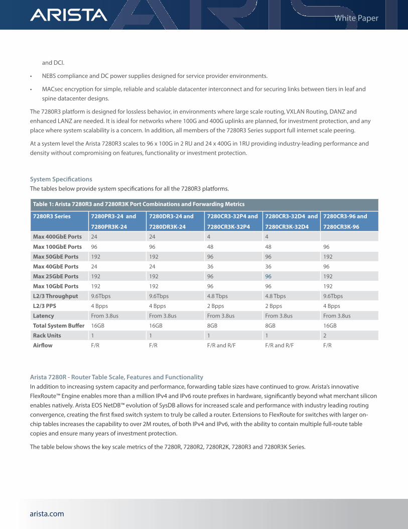
Arista 7280R3 Universal Leaf Platform LayoutArista 7280R3 series switches utilize high performance packet processors, with the number of packet processors varied, based on the number and type of ports on the system. The packet forwarding architecture of each of these systems is essentially the same: a group of front-panel ports (different transceiver/port/speed options) are connected to the packet processor. The following diagrams show the layout of each 7280R3 system.
The 7280CR3-32P4 system utilizes a single Jericho2 chip. A total of 8 gearboxes allows the system to support 32 ports of 100G and a diverse range of optics. Each of the four 400G ports can operate as either 1 x 400G, 2x200G, 4 x 100G, 8 x 50G or 8 x 25G interfaces. Each port is capable of supporting copper or AOC as well as the range of optics available in the OSFP form-factor.
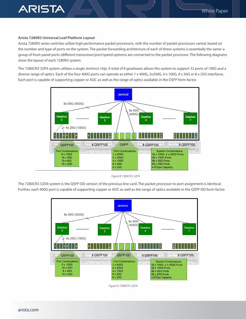
The 7280CR3-32D4 system is the QSFP-DD version of the previous line card. The packet processor to port assignment is identical. Further, each 400G port is capable of supporting copper or AOC as well as the range of optics available in the QSFP-DD form-factor.
Figure 8: 7280CR3-32P4
Figure 9: 7280CR3-32D4

arista.comarista.com
White Paper
The 7280PR3-24 and 7280DR3-24 are 1U systems with two Jericho2 chips to deliver 24 ports of 400G with 9.6Tbps of non-blocking performance. Each 400G port is capable of a range of speeds, offering deployment flexibility. Each port is capable of supporting copper or AOC as well as the range of optics available in either the OSFP or QSFP-DD form-factor.
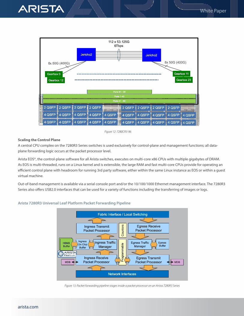
The 7280CR3-96 is a 2U system also with two Jericho2 chips to deliver 9.6Tbps of non-blocking performance. A total of 24 gearboxes allows the system to support 96 ports of 100G and a diverse range of optics.
Figure 10: 7280PR3-24
Figure 11: 7280DR3-24
arista.comarista.com
White Paper
Scaling the Control PlaneA central CPU complex on the 7280R3 Series switches is used exclusively for control-plane and management functions; all data-plane forwarding logic occurs at the packet processor level.
Arista EOS®, the control-plane software for all Arista switches, executes on multi-core x86 CPUs with multiple gigabytes of DRAM. As EOS is multi-threaded, runs on a Linux kernel and is extensible, the large RAM and fast multi-core CPUs provide for operating an efficient control plane with headroom for running 3rd party software, either within the same Linux instance as EOS or within a guest virtual machine.
Out-of-band management is available via a serial console port and/or the 10/100/1000 Ethernet management interface. The 7280R3 Series also offers USB2.0 interfaces that can be used for a variety of functions including the transferring of images or logs.
Arista 7280R3 Universal Leaf Platform Packet Forwarding Pipeline
Figure 13: Packet forwarding pipeline stages inside a packet processor on an Arista 7280R3 Series
Figure 12: 7280CR3-96
arista.comarista.com
White Paper
Each packet processor is a System-on-Chip (SoC) that provides all the ingress and egress forwarding pipeline stages for packets to or from the front panel input ports connected to that packet processor. Forwarding is always hardware-based and never falls back to software for forwarding.
The steps involved at each of the logical stages of the packet forwarding pipeline are outlined below.
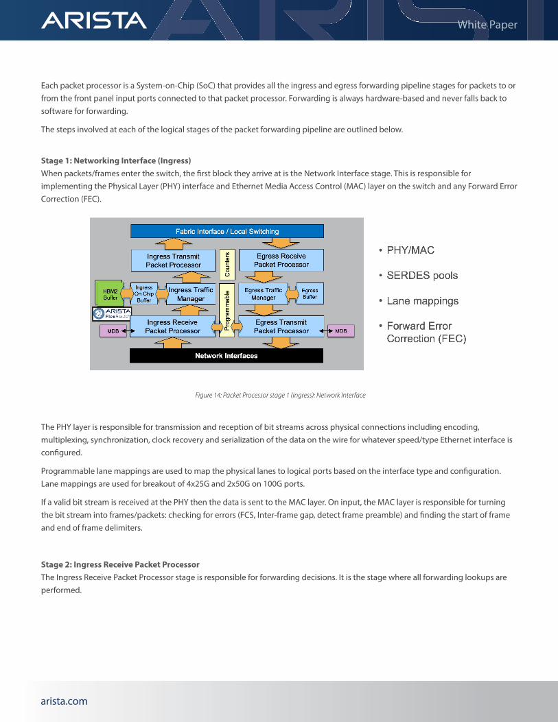
Stage 1: Networking Interface (Ingress)When packets/frames enter the switch, the first block they arrive at is the Network Interface stage. This is responsible for implementing the Physical Layer (PHY) interface and Ethernet Media Access Control (MAC) layer on the switch and any Forward Error Correction (FEC).
The PHY layer is responsible for transmission and reception of bit streams across physical connections including encoding, multiplexing, synchronization, clock recovery and serialization of the data on the wire for whatever speed/type Ethernet interface is configured.
Programmable lane mappings are used to map the physical lanes to logical ports based on the interface type and configuration. Lane mappings are used for breakout of 4x25G and 2x50G on 100G ports.
If a valid bit stream is received at the PHY then the data is sent to the MAC layer. On input, the MAC layer is responsible for turning the bit stream into frames/packets: checking for errors (FCS, Inter-frame gap, detect frame preamble) and finding the start of frame and end of frame delimiters.
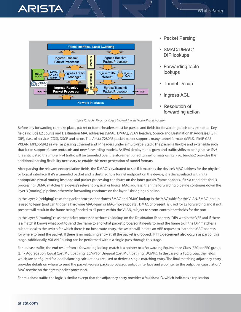
Stage 2: Ingress Receive Packet ProcessorThe Ingress Receive Packet Processor stage is responsible for forwarding decisions. It is the stage where all forwarding lookups are performed.
Figure 14: Packet Processor stage 1 (ingress): Network Interface
arista.comarista.com
White Paper
Before any forwarding can take place, packet or frame headers must be parsed and fields for forwarding decisions extracted. Key fields include L2 Source and Destination MAC addresses [SMAC, DMAC], VLAN headers, Source and Destination IP Addresses [SIP, DIP], class of service (COS), DSCP and so on. The Arista 7280R3 packet parser supports many tunnel formats (MPLS, IPinIP, GRE, VXLAN, MPLSoGRE) as well as parsing Ethernet and IP headers under a multi-label stack. The parser is flexible and extensible such that it can support future protocols and new forwarding models. As IPv6 deployments grow and traffic shifts to being native IPv6 it is anticipated that more IPv4 traffic will be tunneled over the aforementioned tunnel formats using IPv6. Jericho2 provides the additional parsing flexibility necessary to enable this next generation of tunnel formats.
After parsing the relevant encapsulation fields, the DMAC is evaluated to see if it matches the device’s MAC address for the physical or logical interface. If it’s a tunneled packet and is destined to a tunnel endpoint on the device, it is decapsulated within its appropriate virtual routing instance and packet processing continues on the inner packet/frame headers. If it’s a candidate for L3 processing (DMAC matches the device’s relevant physical or logical MAC address) then the forwarding pipeline continues down the layer 3 (routing) pipeline, otherwise forwarding continues on the layer 2 (bridging) pipeline.
In the layer 2 (bridging) case, the packet processor performs SMAC and DMAC lookup in the MAC table for the VLAN. SMAC lookup is used to learn (and can trigger a hardware MAC-learn or MAC-move update), DMAC (if present) is used for L2 forwarding and if not present will result in the frame being flooded to all ports within the VLAN, subject to storm-control thresholds for the port.
In the layer 3 (routing) case, the packet processor performs a lookup on the Destination IP address (DIP) within the VRF and if there is a match it knows what port to send the frame to and what packet processor it needs to send the frame to. If the DIP matches a subnet local to the switch for which there is no host route entry, the switch will initiate an ARP request to learn the MAC address for where to send the packet. If there is no matching entry at all the packet is dropped. IP TTL decrement also occurs as part of this stage. Additionally, VXLAN Routing can be performed within a single pass through this stage.
For unicast traffic, the end result from a forwarding lookup match is a pointer to a Forwarding Equivalence Class (FEC) or FEC group (Link Aggregation, Equal Cost Multipathing [ECMP] or Unequal Cost Multipathing [UCMP]). In the case of a FEC group, the fields which are configured for load balancing calculations are used to derive a single matching entry. The final matching adjacency entry provides details on where to send the packet (egress packet processor, output interface and a pointer to the output encapsulation/MAC rewrite on the egress packet processor).
For multicast traffic, the logic is similar except that the adjacency entry provides a Multicast ID, which indicates a replication
Figure 15: Packet Processor stage 2 (ingress): Ingress Receive Packet Processor
arista.comarista.com
White Paper
requirement for both local (ingress) multicast destinations on local ports, as well as whether there are packet processors in the system that require packet replication via multicast replication in the fabric modules. By default, the Arista 7280R3 Series operates in egress multicast replication but can be configured for ingress multicast replication as well.
The forwarding pipeline always remains in the hardware data-plane. There are no features that can be enabled that cause the packet forwarding to drop out of the hardware-based forwarding path. In cases where software assistance is required (e.g. traffic destined within a L3 subnet but for which the switch has not yet seen the end device provide an ARP and doesn’t have the L3-to-L2 glue entry), hardware rate limiters and Control Plane Policing are employed to protect the control-plane from potential denial of service attacks.
In parallel with forwarding table lookups, there are also Ingress ACL lookups (Port ACLs, Routed ACLs) for applying security and QoS lookups to apply Quality of Service. All lookups are ultimately resolved using strength based resolution (some actions are complementary and multiple actions are applied, some actions override others) but ultimately the outcome of this stage is a resolved forwarding action.
Counters are available within this stage providing accounting and statistics on ACLs, VLAN and sub-interfaces, as well as a range of tunnel and next-hop group types. The R3-series systems provide significant gains in overall counter scale and flexibility in allocation over previous generations, providing a 5X increase in scale in some dimensions. The criticality of flexibility in counter scaling cannot be overstated as operators migrate to next generation technologies such as Segment Routing and the use of various overlay tunnel technologies that rely upon fine-grained network utilization information to accurately place network workloads.
Data plane counters are available in real-time via streaming telemetry using NetDB to export using gRPC with OpenConfig.
Arista FlexRouteTM EngineOne of the key characteristics of the Arista 7280R3 Universal Leaf platform is the FlexRoute Engine, an Arista innovation which enables Internet scale L3 routing tables with significant power consumption savings over legacy IP routing longest prefix match lookups. This in turn enables higher port densities and performance with power and cooling advantages when compared to legacy service provider routing platforms.
Arista’s FlexRoute Engine is used for both IPv4 and IPv6 Longest Prefix Match (LPM) lookups without partitioning table resources. It is optimized around the Internet routing table, its prefix distribution and projected growth. FlexRoute enables scale beyond 1.4 million IPv4 and IPv6 prefixes combined, providing headroom for internet table growth for many years.
In addition to large table support, FlexRoute enables very fast route programming and reprogramming (tens of thousands of prefixes per second), and does so in a manner that is non-disruptive to other prefixes while forwarding table updates are taking place.
All Arista 7280R3 Series systems take advantage of the multi-stage programmable forwarding pipeline to provide a flexible and scalable solution for access control, secure policy based networking and telemetry in today’s cloud networks. ACLs are not constrained by the size of fixed hardware tables, but can leverage the forwarding lookup capabilities of the packet processor to trigger a wide range of traffic management actions.
sFlowThe programmable packet processing pipeline on the 7280R3 platform enables a range of new telemetry capabilities for network operators. In addition to new counter capabilities, flow instrumentation capabilities are enhanced through the availability of hardware accelerated sFlow. As network operators deploy various tunnel overlay technologies in their network, sFlow provides

arista.comarista.com
White Paper
an encapsulation independent means of getting visibility into high-volume traffic flows and enables operators to more effectively manage and steer traffic to maximize utilization. The programmable pipeline provides these capabilities inline without requiring an additional coprocessor. Sampling granularity of 1:100 on 100G and 400G interfaces can be realized on all interfaces.
Inband Network Telemetry (INT)As a complement to sFlow, INT provides operators with a standards-based means of getting insight into per hop latency, paths, congestion and drops. This information can be correlated to allow analysis of hotspots, path topology to influence traffic engineering decisions. INT provides operators with a data plane aware complement to standard IP/MPLS troubleshooting tools. Where ping and traceroute cannot necessarily confirm whether or not a flow traverses a specific interface in a port-channel, INT provides operators with a path and node traversal details by processing inband OAM frames and annotating these frames with metadata to provide detailed path and transit quality details. The programmable pipeline in the R3-series systems provides the ability to facilitate this packet processing inline.
Stage 3: Ingress Traffic Manager The Ingress Traffic Manager stage is responsible for packet queuing and scheduling.
Arista 7280R3 Universal Leaf platforms utilize Virtual Output Queuing (VoQ) where the majority of the buffering within the switch is on the ingress port. While the physical buffer is on the input packet processor, it represents packets queued on the output side (hence, the term virtual output queuing). VoQ is a technique that allows buffers to be balanced across sources contending for a congested output port and ensures fairness and QoS policies can be implemented in a distributed forwarding system.
When a packet arrives into the Ingress Traffic Manager, a VoQ credit request is forwarded to the egress port processor requesting a transmission slot on the output port. Packets are queued on ingress until such time as a VoQ grant message is returned (from the Egress Traffic Manager on the output port) indicating that the Ingress Traffic Manager can forward the frame to the egress packet processor.
While the VoQ request/grant credit cycle is under way, the packet is queued in input buffers. A combination of on-chip memory (32MB) and external memory (8GB) per packet processor is used to store packets while awaiting the VoQ grant. The memory is used such that traffic destined to uncongested outputs (egress VoQ is empty) will go into on-chip memory (head of the queue) otherwise external buffer memory is utilized. External buffer memory is used because it’s impractical to build sufficiently large buffers on-chip due to the very large chip die area that would be consumed.
Figure 16: Packet Processor stage 3 (ingress): Ingress Traffic Manager
arista.comarista.com
White Paper
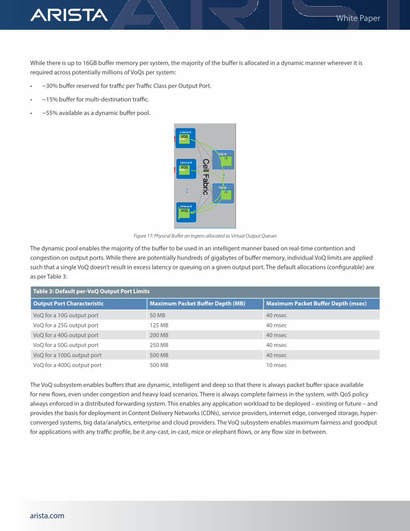
While there is up to 16GB buffer memory per system, the majority of the buffer is allocated in a dynamic manner wherever it is required across potentially millions of VoQs per system:
• ~30% buffer reserved for traffic per Traffic Class per Output Port.
• ~15% buffer for multi-destination traffic.
• ~55% available as a dynamic buffer pool.
The dynamic pool enables the majority of the buffer to be used in an intelligent manner based on real-time contention and congestion on output ports. While there are potentially hundreds of gigabytes of buffer memory, individual VoQ limits are applied such that a single VoQ doesn’t result in excess latency or queuing on a given output port. The default allocations (configurable) are as per Table 3:
The VoQ subsystem enables buffers that are dynamic, intelligent and deep so that there is always packet buffer space available for new flows, even under congestion and heavy load scenarios. There is always complete fairness in the system, with QoS policy always enforced in a distributed forwarding system. This enables any application workload to be deployed – existing or future – and provides the basis for deployment in Content Delivery Networks (CDNs), service providers, internet edge, converged storage, hyper-converged systems, big data/analytics, enterprise and cloud providers. The VoQ subsystem enables maximum fairness and goodput for applications with any traffic profile, be it any-cast, in-cast, mice or elephant flows, or any flow size in between.
Figure 17: Physical Buffer on Ingress allocated as Virtual Output Queues
Table 3: Default per-VoQ Output Port Limits
Output Port Characteristic Maximum Packet Buffer Depth (MB) Maximum Packet Buffer Depth (msec)
VoQ for a 10G output port 50 MB 40 msec
VoQ for a 25G output port 125 MB 40 msec
VoQ for a 40G output port 200 MB 40 msec
VoQ for a 50G output port 250 MB 40 msec
VoQ for a 100G output port 500 MB 40 msec
VoQ for a 400G output port 500 MB 10 msec
arista.comarista.com
White Paper
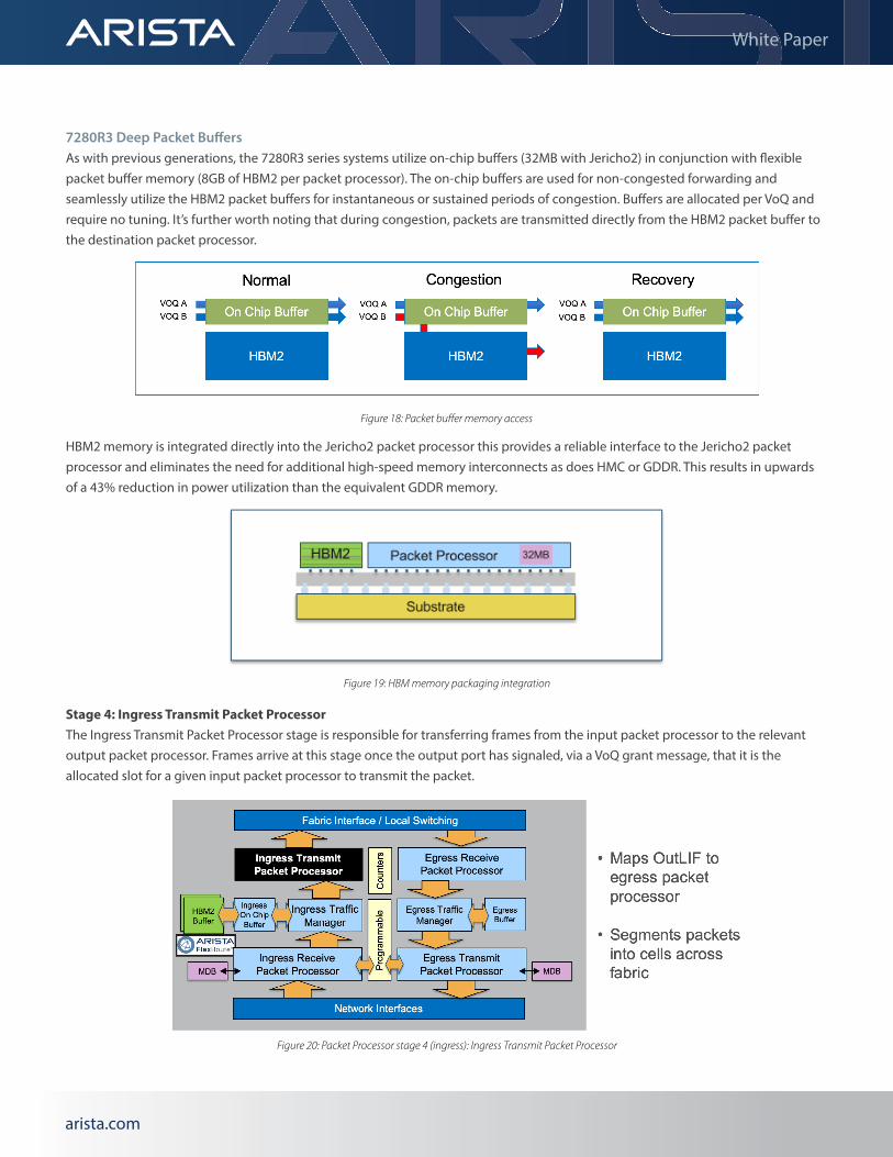
7280R3 Deep Packet BuffersAs with previous generations, the 7280R3 series systems utilize on-chip buffers (32MB with Jericho2) in conjunction with flexible packet buffer memory (8GB of HBM2 per packet processor). The on-chip buffers are used for non-congested forwarding and seamlessly utilize the HBM2 packet buffers for instantaneous or sustained periods of congestion. Buffers are allocated per VoQ and require no tuning. It’s further worth noting that during congestion, packets are transmitted directly from the HBM2 packet buffer to the destination packet processor.
HBM2 memory is integrated directly into the Jericho2 packet processor this provides a reliable interface to the Jericho2 packet processor and eliminates the need for additional high-speed memory interconnects as does HMC or GDDR. This results in upwards of a 43% reduction in power utilization than the equivalent GDDR memory.
Stage 4: Ingress Transmit Packet ProcessorThe Ingress Transmit Packet Processor stage is responsible for transferring frames from the input packet processor to the relevant output packet processor. Frames arrive at this stage once the output port has signaled, via a VoQ grant message, that it is the allocated slot for a given input packet processor to transmit the packet.
Figure 18: Packet buffer memory access
Figure 19: HBM memory packaging integration
Figure 20: Packet Processor stage 4 (ingress): Ingress Transmit Packet Processor

arista.comarista.com
White Paper
All available paths are used in parallel to transfer the frame or packet to the output packet processor, with the original packet segmented into variable-sized cells which are forwarded across the fabric links simultaneously. This mechanism reduces serialization to at most 256 bytes at 50Gbps and ensures there are no hot spots as every flow is always evenly balanced across all paths. Since a packet is only transferred once there is a VoQ grant, there are guaranteed to be resources to process the frame on the egress packet processor.
Each cell has a header added to the front for the receiving packet processor to be able to reassemble and maintain in-order delivery. Forward Error Correction (FEC) is also enabled for traffic across the fabric modules, both to correct errors (if they occur) but also to help monitor data-plane components of the system for any problems.
Packets destined to ports on the same packet processor are switched locally and do not use fabric bandwidth resources, but otherwise aren’t processed any differently in terms of the VoQ subsystem.
Stage 5: Egress Receive Packet ProcessorThe Egress Receive Packet Processor stage is responsible for reassembling cells back into packets/frames. This is also the stage that takes a multicast packet/frame and replicates it when there are multiple locally attached receivers on this output packet processor.
This stage ensures that there is no frame or packet reordering in the system. It also provides the data-plane health tracer, validating reachability messages from all other packet processors across all paths in the system.
Egress ACLs are also performed at this stage based on the packet header updates, and once the packet passes all checks, it is transmitted on the output port.
Stage 6: Egress Traffic ManagerThe Egress Traffic Manager stage is responsible for the granting of VoQ credit requests from input packet processors and managing egress queues.
Figure 21: Packet Processor stage 5 (egress): Egress Receive Packet Processor

arista.comarista.com
White Paper
When an ingress packet processor requests to schedule a packet to the egress packet processor it is the Egress Traffic Manager stage that receives the request. If the output port is not congested then it will grant the request immediately. If there is congestion it will fairly balance the service requests between contending input ports, within the constraints of QoS configuration policy (e.g. output port shaping) while also conforming to PFC/ETS traffic scheduling policies on the output port. Scheduling between multiple contending inputs for the same queue can be configured to weighted fair queuing (WFQ) or round-robin.
The Egress Traffic Manager stage is also responsible for managing egress buffering within the system. There is an additional 32MB on-chip buffer used for egress queuing. This buffer is primarily reserved for multicast traffic as unicast traffic has a minimal requirement for egress buffering due to the large ingress VoQ buffer and fair adaptive dynamic thresholds are utilized as a pool of buffers for the output ports.
Stage 7: Egress Transmit Packet Processor
In this stage, any packet header updates such as updating the next-hop DMAC, Dot1q updates and tunnel encapsulation operations are performed based on packet header rewrite instructions passed from the Input Receive Packet Processor stage. Decoupling the packet forwarding on ingress from the packet rewrite on egress provides the ability to increase the next-hop and tunnel scale of the system as these resources are programmed in a distributed manner.
Figure 22: Packet Processor stage 6 (egress): Egress Receive Packet Processor
Figure 23: Packet Processor stage 7 (egress): Egress Transmit Packet Processor
arista.comarista.com
White Paper
This stage can also optionally set TCP Explicit Congestion Notification (ECN) bits based on whether there was contention on the output port and the time the packet spent queued within the system from input to output. Flexible Counters are available at this
stage and can provide packet and byte counters on a variety of tables.
Stage 8: Network Interface (Egress)Just as packets/frames entering the switch went through the Ethernet MAC and PHY layer with the flexibility of multi-speed interfaces, the same mechanism is used on packet/frame transmission. Packets/frames are transmitted onto the wire as a bit stream in compliance with IEEE 802.3 standards.
Arista EOS: A Platform For Scale, Stability and ExtensibilityAt the core of the Arista 7280R3 Universal Leaf platform is Arista EOS® (Extensible Operating System). Built from the ground up using innovative core technologies since our founding in 2004, EOS contains more than 8 million lines of code and years of advanced distributed systems software engineering. EOS is built to be open and standards-based and its modern architecture delivers better reliability and is uniquely programmable at all system levels.
EOS has been built to address two fundamental issues that exist in cloud networks: the need for non-stop availability and the need for high feature velocity coupled to high quality software. Drawing on our engineers experience in building networking products over more than 30 years, and on the state-of-the-art in open systems technology and distributed systems, Arista started from a clean sheet of paper to build an operating system suitable for the cloud era.
At its foundation, EOS uses a unique multi-process state-sharing architecture which separates system state information from packet forwarding and from protocol processing and application logic. In EOS, system state and data is stored and maintained in a highly efficient System Database (SysDB). The data stored in SysDB is accessed using an automated publish/subscribe/notify model. This architecturally distinct design principle supports self-healing resiliency in our software, eases software maintenance and enables module independence. This results in higher software quality overall, and accelerates time-to-market for the new features that customers require.
Arista EOS contrasts with the legacy approach to building network operating systems developed in the 1990’s that relied upon embedding system state within each independent process, relying on extensive use of inter-process communications (IPC) mechanisms to maintain state across the system, with a manual integration of subsystems. These legacy system architectures lack an automated structured core like SysDB. In legacy network operating systems, as dynamic events occur in large networks or in the face of a system process failure and restart, recovery can be difficult if not impossible.
Additionally, as legacy network operating systems attempt to adapt to industry demands, such as streaming telemetry, individual subsystems must be manually extended to support state export into a system which was never designed to facilitate cloud-scale export mechanisms. As such, stabilizing and adapting to a wide range of telemetry and control protocols remains an ongoing challenge complicating integration and delaying migration to next-generation management interfaces for operators.
arista.comarista.com
White Paper
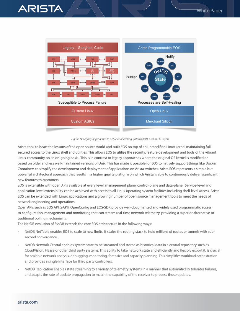
Arista took to heart the lessons of the open source world and built EOS on top of an unmodified Linux kernel maintaining full, secured access to the Linux shell and utilities. This allows EOS to utilize the security, feature development and tools of the vibrant Linux community on an on-going basis. This is in contrast to legacy approaches where the original OS kernel is modified or based on older and less well-maintained versions of Unix. This has made it possible for EOS to natively support things like Docker Containers to simplify the development and deployment of applications on Arista switches. Arista EOS represents a simple but powerful architectural approach that results in a higher quality platform on which Arista is able to continuously deliver significant new features to customers.EOS is extensible with open APIs available at every level: management plane, control-plane and data-plane. Service-level and application-level extensibility can be achieved with access to all Linux operating system facilities including shell-level access. Arista EOS can be extended with Linux applications and a growing number of open source management tools to meet the needs of network engineering and operations.Open APIs such as EOS API (eAPI), OpenConfig and EOS-SDK provide well-documented and widely used programmatic access to configuration, management and monitoring that can stream real-time network telemetry, providing a superior alternative to traditional polling mechanisms.The NetDB evolution of SysDB extends the core EOS architecture in the following ways:
• NetDB NetTable enables EOS to scale to new limits. It scales the routing stack to hold millions of routes or tunnels with sub-second convergence.
• NetDB Network Central enables system state to be streamed and stored as historical data in a central repository such as CloudVision, HBase or other third party systems. This ability to take network state and efficiently and flexibly export it, is crucial for scalable network analysis, debugging, monitoring, forensics and capacity planning. This simplifies workload orchestration and provides a single interface for third party controllers.
• NetDB Replication enables state streaming to a variety of telemetry systems in a manner that automatically tolerates failures, and adapts the rate of update propagation to match the capability of the receiver to process those updates.
Figure 24: Legacy approaches to network operating systems (left), Arista EOS (right)
arista.comarista.com
White Paper
The evolution of SysDB to NetDB builds on the core principles that have been the foundation of the success of EOS: openness, programmability, and quality on a single build of EOS runs across all of our products.
System Health Tracer And Integrity ChecksJust as significant engineering effort has been invested in the software architecture of Arista EOS, the same level of detail has gone into system health and integrity checks within the system. There are numerous subsystems on Arista 7280R3 Universal Leaf platform switches that validate and track the system health and integrity on a continual basis:
• All memories where code executes (control-plane and data-plane) are ECC protected; single bit errors are detected and corrected automatically, double bit errors are detected.
• All data-plane forwarding tables are parity protected with shadow copies kept in ECC protected memory on the control-plane. Continual hardware table validation verifies that the hardware tables are valid and truthful.
• All data-plane packet buffers are protected using CRC32 checksums from the time a packet/frame arrives to the time it leaves the switch. The checksum is validated at multiple points through the forwarding pipeline to ensure no corruption has happened, or if there has been a problem, rapidly facilitate its isolation.
• Forward Error Correction (FEC) is also utilized for traffic across the fabric modules, both to correct errors (if they occur) but also to help monitor data-plane components of the system for problems.
• Data-plane forwarding elements are continually testing and checking reachability with all other forwarding elements in the system. This is to insure that if there are issues they can be accurately and proactively resolved.
arista.comarista.comarista.com
Santa Clara—Corporate Headquarters5453 Great America Parkway, Santa Clara, CA 95054
Phone: +1-408-547-5500 Fax: +1-408-538-8920 Email: [email protected]
Ireland—International Headquarters 3130 Atlantic Avenue Westpark Business Campus Shannon, Co. Clare Ireland
Vancouver—R&D Office 9200 Glenlyon Pkwy, Unit 300 Burnaby, British Columbia Canada V5J 5J8
San Francisco—R&D and Sales Office 1390 Market Street, Suite 800 San Francisco, CA 94102
India—R&D Office Global Tech Park, Tower A & B, 11th Floor Marathahalli Outer Ring Road Devarabeesanahalli Village, Varthur Hobli Bangalore, India 560103
Singapore—APAC Administrative Office 9 Temasek Boulevard #29-01, Suntec Tower Two Singapore 038989
Nashua—R&D Office 10 Tara Boulevard Nashua, NH 03062
White Paper
Copyright © 2016 Arista Networks, Inc. All rights reserved. CloudVision, and EOS are registered trademarks and Arista Networks is a trademark of Arista Networks, Inc. All other company names are trademarks of their respective holders. Information in this document is subject to change without notice. Certain features may not yet be available. Arista Networks, Inc. assumes no responsibility for any errors that may appear in this document. 04/20 02-0087-01
ConclusionDesigned to address the demands of the world’s largest cloud and service providers the Arista 7280R3 Series switches continue to provide operators with a proven, industry leading, platform to evolve their network capabilities. By combining industry leading 400G density with Internet scale service capabilities and next generation packet processing functionality at the optimum intersection of performance and power utilization.
The 7280R3 leverages the proven architecture that has made the previous generations of the product so successful; focus on efficient system design, reliability and flexibility. This trend continues with innovations in the packet processors powering the R3-series, enabling operators to use the 7280R3 in an ever wider range of roles with a single hardware platform.
Arista’s EOS network operating system continues to lead the industry in openness, extensibility and software quality. EOS has been leading the industry in telemetry innovations through the availability of NetDB and enabled operators to truly automate their network deployments through rich programmatic interfaces and support for industry standards such as OpenConfig.
Given the cloud scale hardware and software capabilities of the 7280R3, it makes the ideal platform for a range of applications. The 7280R3 is ideally suited for cloud scale data centers, Service Provider WAN backbones and Peering edges as well as large enterprise networks.