Embed Size (px)
Citation preview

A UTC Fire & Security Company
Effective: July 2012K-38-1000
Argonite®
System Description
FEATURES
• Inert Gas Clean Agent Fire Suppression
• Safe for Personnel and Equipment
• Leaves No Residue
• Environmentally Friendly
• Actuation by Solenoid or Manual Actuator
• Three Available High-pressure (2900 PSI [200 bar]) Cylinder Sizes
• FM Approved/ULC Listed
DESCRIPTIONKidde Argonite® Fire Protection Systems are cleanagent, automatic extinguishing systems that use Argonite(IG-55) and consist of four basic components and theirassociated accessories:
• Argonite Cylinders and Components,• Completer Kits,• Control Panels,• Detection and Alarm Devices.
Argonite is an inert gas mixture, in equal parts, of Nitro-gen and Argon. Both substances are naturally occurringand present in the atmosphere. Argonite is safe for use inoccupied spaces and poses no threat to the environment.
1. Argonite Components consist of the agent cylinders,cylinder racking and the agent discharge nozzles.
2. The Completer Kits provide all the basic compo-nents necessary to operate the Argonite cylinders.The kits consist of hoses, connection fittings, pres-sure gauges, actuation devices required to operatethe cylinder valve and warning signs to be displayedin the area(s) protected by an Argonite fire extin-guishing system.
3. The Control Panels vary in features and complexitybut in all cases are used to monitor the detection,actuate the alarms, initiate the agent discharge andcontrol auxiliary functions such as shut down of vitalequipment and ventilation dampers.
4. The Detection and Alarm devices provide fire detec-tion by means of thermal or smoke detectors, audi-ble and visual pre-alarm warnings and annunciationof the Argonite discharge.
AGENT DESCRIPTIONArgonite is a mixture of 50% pure Nitrogen and 50% pureArgon. Argonite contains only naturally occurring sub-stances, and as such, has no ozone depletion potentialand no direct global warming potential.
Argonite extinguishes by means of reducing the oxygencontent within a room to the point at which fire can nolonger burn, but without compromising the safety of indi-viduals present. There are no toxicological factors asso-ciated with the use of Argonite. Argonite will notdecompose or produce any by-products when exposedto a flame from a fire condition.
Most Argonite systems are designed to extinguish fireswith a minimum agent concentration of 37.9% achievedwithin one minute. This results in extinguishment of thefire and an oxygen concentration of 13%.
Argonite is stored as a gas within the cylinder assembly.It is available at a storage pressure of 2900 PSI (200bar).

USABLE CYLINDER CAPACITYThree cylinder sizes are available (see Table 1).
Table 1. Cylinder Capacity
Figure 1. Argonite Cylinder
Table 2. Argonite cylinder Area Coverage
EQUIPMENT DESCRIPTIONThe Kidde Fire Systems Argonite Fire Protection Systemcan be released electrically, manually or pneumatically.The following is a description of the various componentsassociated with the systems.
CYLINDER AND VALVE ASSEMBLYArgonite cylinders are available in three different sizes.The 2900 PSI (200 bar) cylinders are uniquely colorcoded to allow for quick and easy identification. The cyl-inders are red with yellow-green at the cylinder shoulder.
Because Argonite is stored as a gas, the cylinders haveno dip tube and can be mounted in either the vertical orhorizontal position.
The cylinder valve, required for all system cylinders,allows for connection of the cylinders into the system.The valve provides connections for electric, pneumaticand manual release of the cylinder contents, as well as adischarge outlet, connected by a discharge hose, to thedistribution piping.
The actuator operates on a 1 to 10 ratio requiring only300 PSI (21 bar) for the 2900 PSI (200 bar) system tooperate the valve. The following are the connections pro-vided on the valve.
Figure 2. Cylinder Dimensions
Table 3. Cylinder Dimensions
Size Fill
English Metric at 2900 PSI at 200 Bar
972 cu. in. 15.9 L * 9.57 lb. 4.34 kg
4079 cu. in. 66.7 L * 40.15 lb. 18.21 kg
4893 cu. in. 80.0 L 48.13 lb. 21.83 kb
CylinderArea Coverage @
38% Concentration/70°F (21°C)
15.9 L * 228.8 ft.3 (6.47 m3)
66.7 L * 959.8 ft.3 (27.17 m3)
80.0 L 1150.6 ft.3 (32.58 m3)
A
B
Cylinder Size
Dimension
AB
(Diameter)
15.9 L * 39.07 in.(992.38 mm)
7.00 in.(177.80 mm)
66.7 L * 64.41 in. (1636.10 mm)
10.49 in.(266.45 mm)
80.0 L68.81 in.
(1747.77 mm)11.25 in.
(285.75 mm)
* DISCONTINUED
- 2 -
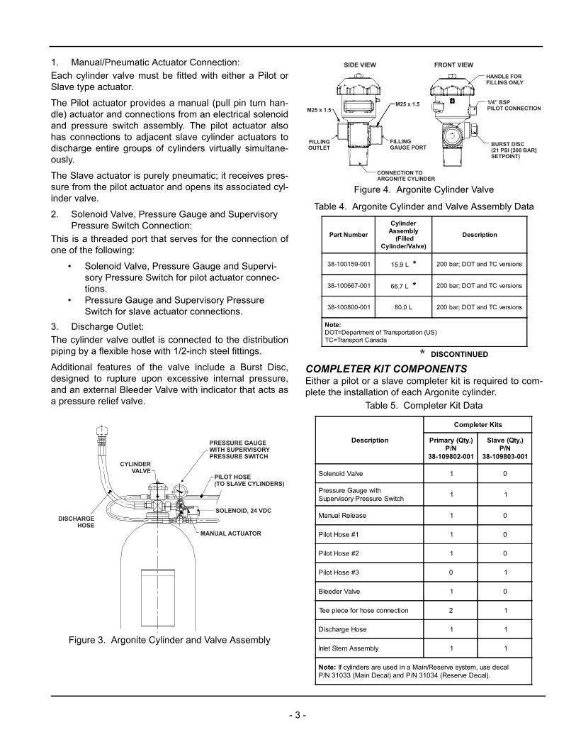
1. Manual/Pneumatic Actuator Connection:
Each cylinder valve must be fitted with either a Pilot orSlave type actuator.
The Pilot actuator provides a manual (pull pin turn han-dle) actuator and connections from an electrical solenoidand pressure switch assembly. The pilot actuator alsohas connections to adjacent slave cylinder actuators todischarge entire groups of cylinders virtually simultane-ously.
The Slave actuator is purely pneumatic; it receives pres-sure from the pilot actuator and opens its associated cyl-inder valve.
2. Solenoid Valve, Pressure Gauge and Supervisory Pressure Switch Connection:
This is a threaded port that serves for the connection ofone of the following:
• Solenoid Valve, Pressure Gauge and Supervi-sory Pressure Switch for pilot actuator connec-tions.
• Pressure Gauge and Supervisory Pressure Switch for slave actuator connections.
3. Discharge Outlet:
The cylinder valve outlet is connected to the distributionpiping by a flexible hose with 1/2-inch steel fittings.
Additional features of the valve include a Burst Disc,designed to rupture upon excessive internal pressure,and an external Bleeder Valve with indicator that acts asa pressure relief valve.
Figure 3. Argonite Cylinder and Valve Assembly
Figure 4. Argonite Cylinder Valve
Table 4. Argonite Cylinder and Valve Assembly Data
COMPLETER KIT COMPONENTSEither a pilot or a slave completer kit is required to com-plete the installation of each Argonite cylinder.
Table 5. Completer Kit Data
DISCHARGEHOSE
CYLINDERVALVE
PRESSURE GAUGEWITH SUPERVISORYPRESSURE SWITCH
PILOT HOSE(TO SLAVE CYLINDERS)
SOLENOID, 24 VDC
MANUAL ACTUATOR
M25 x 1.5
FRONT VIEW
M25 x 1.5
SIDE VIEW
FILLINGOUTLET
FILLINGGAUGE PORT
CONNECTION TOARGONITE CYLINDER
HANDLE FORFILLING ONLY
1/4” BSPPILOT CONNECTION
BURST DISC(21 PSI [300 BAR]SETPOINT)
Part Number
CylinderAssembly
(FilledCylinder/Valve)
Description
38-100159-001 15.9 L * 200 bar; DOT and TC versions
38-100667-001 66.7 L * 200 bar; DOT and TC versions
38-100800-001 80.0 L 200 bar; DOT and TC versions
Note:DOT=Department of Transportation (US)TC=Transport Canada
Description
Completer Kits
Primary (Qty.)P/N
38-109802-001
Slave (Qty.)P/N
38-109803-001
Solenoid Valve 1 0
Pressure Gauge withSupervisory Pressure Switch
1 1
Manual Release 1 0
Pilot Hose #1 1 0
Pilot Hose #2 1 0
Pilot Hose #3 0 1
Bleeder Valve 1 0
Tee piece for hose connection 2 1
Discharge Hose 1 1
Inlet Stem Assembly 1 1
Note: If cylinders are used in a Main/Reserve system, use decalP/N 31033 (Main Decal) and P/N 31034 (Reserve Decal).
* DISCONTINUED
- 3 -

SOLENOID AND PRESSURE GAUGE ASSEMBLY WITH SUPERVISORY PRESSURE SWITCHThe solenoid/pressure gauge assembly provides an elec-trical means (24 Vdc) of actuating the system as well as avisual means to determine the pressure within the pilotcylinder.
This unit includes an integral supervisory pressure switchand is supplied with a pilot flex hose #1. The supervisorypressure switch consists of one normally open (N.O.)contact that changes state upon loss of cylinder pres-sure.
Figure 5. Solenoid and Pressure Switch Gauge Assembly with Supervisory Pressure Switch
PRESSURE GAUGE ASSEMBLYWITH SUPERVISORY PRESSURE SWITCH, P/N 38-109891-001This unit is required for the slave cylinders to provide alocal visual means to determine the pressure within theslave cylinder.
The pressure gauge assembly includes an integralsupervisory pressure switch, consisting of one N.O. con-tact that changes state upon loss of cylinder pressure.
PILOT FLEX HOSE #1, P/N 38-509818-001This 1/4-inch ID reinforced rubber flex hose has threadedconnections to allow interface between the pilot cylindersolenoid/pressure gauge assembly and pilot manual/pneumatic actuator. It is supplied with the pilot solenoidassembly.
Figure 6. Pilot Flex Hose #1
MANUAL/PNEUMATIC ACTUATOR, P/N 38-509841-001The manual/pneumatic actuator supplied with the pilotcompleter kit is required on the pilot cylinder to manuallyactuate the cylinder valve as well as to supply pressureto actuate any slave cylinders. Interconnection betweencylinders is by means of high-pressure flex hoses.
Figure 7. Manual/Pneumatic Actuator
TEE FITTING, 19 MM HEX(CONNECTION TO VALVE)P/N 38-509816-001
TOP VIEW(SHOWN ON CYLINDER)
SOLENOID, 24 VDCP/N 38-509834-001
GAUGE WITHSUPERVISORY
PRESSURE SWITCHP/N 38-109891-001
MANUALPNEUMATIC ACTUATOR
P/N 38-509841-001
SOLENOID,24 VDC
BLEEDER VALVEP/N 38-509840-001
CONNECTIONTO CYLINDER VALVE
36 MM HEX
FRONT VIEW SIDE VIEW
HIGH-PRESSUREREINFORCED RUBBER HOSE
1/4 IN. (6.4 MM); 60° FLARESWIVEL NUT
1/4 IN. (6.4 MM) CONNECTOR
15¾ IN. (400 MM) LONG
TO TEE PIECETO TEE PIECE
PRESSUREINLET
PRESSUREINLET
- 4 -

TEE PIECE FOR HOSE CONNECTIONS, P/N 38-509816-001The tee piece is supplied with each of the completer kits.It provides the interface with the pilot assembly (througha high pressure flex hose) to simultaneously operate theslave cylinder pneumatically.
Figure 8. Tee Piece
BLEEDER VALVE FOR ACTUATOR, P/N 38-509840-001A bleeder valve is included with the Pilot Completer Kit toprevent an accidental accumulation of pressure withinthe pilot lines, which, if not bled to atmosphere, couldcause a false discharge. Connection requires a coppergasket between the bleeder valve and pneumatic actua-tor.
PILOT FLEX HOSESThis 1/4-inch ID reinforced rubber flex hose has threadedconnections to allow interface between components.
Figure 9. Pilot Flex Hose
Table 6. Pilot Flex Hose Data
DISCHARGE FLEX HOSE, P/N 38-509819-001This flex hose has 1/2-inch threaded connections to allowinterface between the cylinder valves and the dischargemanifold (if applicable). Where more than one cylinder isconnected to a common manifold, check valves arerequired at the end of each discharge flex hose.
Figure 10. Discharge Flex Hose
CHECK VALVE ASSEMBLY, P/N 38-509833-001To prevent accidental discharge of the Argonite into unin-tended areas, a check valve is required for each dis-charge hose in all multi-cylinder systems. All Kidde FireSystems manifolds are constructed of threaded pipe withwelded check valve connections and includepre-installed check valves. All customer connections arevia threaded pipe.
Note: For single cylinder systems, a 1/2-inch BSP x 1/2-inch FNPT adapter is required to connect the discharge hose (BSP) to the Schedule 160 pipe (NPT).
Figure 11. Check Valve Assembly
TO CYLINDERVALVE ACTUATION
OUTLET TO
ACTUATE CYLINDER
INLET FROMSOLENOID ORPRIMARY CYLINDER
1/4 IN. (6.4 MM); 60° FLARESWIVEL NUT
HIGH-PRESSUREREINFORCED RUBBER HOSE
1/4 IN. (6.4 MM) CONNECTOR
LENGTH
Part Number Description Length
38-509817-001Pilot Hose #3 between cylinderactuation pieces
10-5/8 in.(270 mm)
38-509820-001Pilot Hose #2 between actuator andcylinder valve
17-3/4 in.(450 mm)
1/2 IN. (12.7 MM)SWIVEL NUT HIGH-PRESSURE
REINFORCED RUBBER HOSE
3/8 IN. (9.5 MM); 60° FLARESWIVEL NUT
3/8 IN. (9.5 MM) CONNECTOR
15¾ IN. (406 MM) LONG
CONNECTION FORMANIFOLD
3/4” NPT
0.79 in.(20 mm)
2.24 in.(57 mm)
0.59 in.(15 mm)
1/2” BSP
CONNECTION FORDISCHARGE HOSE
1.06HEX
60°
- 5 -

FLOW RESTRICTORThe restrictor assembly reduces the initial Argonite pres-sure from the discharge manifold to between 174 and870 PSI (12 and 60 bar) before entering the dischargepiping. The size of the orifice within the restrictor is deter-mined through calculations based upon the required flowand discharge time.
Larger diameter restrictors, up to 4 in. (102 mm) connec-tion, are available for very large system requirements. Anorifice plate is custom drilled to the specific requirementsof the project as determined by computerized flow calcu-lations.
Note: Flanged restrictor for large system requirements. Only the orifice plate is provided.
Figure 12. Flow Restrictor
Table 7. Flow Restrictor Sizes
Figure 13. Restrictor Female NPT/Female NPT, Sizes 1/2-inch to 2 inches
Table 8. Flow Restrictor Data
Part Number Description
38-250001-xxx 2-1/2 in. Flow Restrictor
38-300001-xxx 3 in. Flow Restrictor
38-400001-xxx 4 in. Flow Restrictor
FLOW
BOLT*
CLASS 1500#FLANGE*
NUT*
GASKET*
ORIFICE PLATERESTRICTOR
* PROVIDED BYINSTALLER
Part NumberFlow Restrictor FNPT x FNPT Pipe Diameter
(NPT)
38-050003-xxx 1/2 in. (13 mm) Brass, Code 035 to 075
38-100003-xxx 1 in. (25 mm) Brass, Code 050 to 130
38-150003-xxx 1-1/2 in. (38 mm) Brass, Code 085 to 220
38-200003-xxx 2 in. (51 mm) Stainless Steel, Code 115 to 270
STAMPED WITHORIFICE DIA.
STAMPED WITHPART NUMBER
CONNECTION FORDISTRIBUTIONPIPE WORK
NPT
NPT
38
-XX
00
03
-XX
X
- 6 -

SELECTOR VALVESArgonite systems are particularly suited to the use ofselector valves, where one central storage of agent isused to provide protection to two or more hazard areas.
Selector valves are available in six sizes, and are pneu-matically operated. One common pressure regulator andvented elbow are also required to reduce the actuationpressure to each set of selector valves.
Figure 14. Selector Valve System
Table 9. Selector Valves and Components
NOZZLESThe brass discharge nozzles are available in four basicsizes 1/2-inch, 3/4-inch, 1-inch and 1-1/2-inch. Each is fit-ted with a drilled orifice to assure proper flow rates, agentquality and proper discharge timing as determined byflow calculations. Maximum nozzle spacing for roommounted nozzles should not exceed 18.8 feet (5.7 m)square. Nozzle height should not exceed 16 feet (4.9 m)from a single layer of nozzles.
Figure 15. Nozzles (37 mm)
Table 10. Argonite Discharge Nozzle Data
Part Number Description
38-609800-001 1/2 in. (13 mm) Pipe Diameter
38-609800-002 3/4 in. (19 mm) Pipe Diameter
38-609800-003 1 in. (25 mm) Pipe Diameter
38-609800-004 1-1/4 in. (32 mm) Pipe Diameter
38-609800-005 1-1/2 in. (38 mm) Pipe Diameter
38-609800-006 2 in. (52 mm) Pipe Diameter
38-509803-001 Pressure regulator kit with relief 120 PSI (8.3 bar) preset for selector valves
REDUCING BUSHING*
PRESSURE RELIEF DEVICE,P/N 38-509836-001
SELECTOR VALVE,1/2” TO 2” NPT
RESTRICTOR1/2” TO 2” NPT
OUTLET FROMRESTRICTOR TOHAZARD #2
OUTLET FROMRESTRICTOR TOHAZARD #1
*NOTE: ALL FITTINGS, NIPPLES AND HOSES ARE PROVIDED BY INSTALLER
HANDLE FORMANUAL OPERATION
CYLINDER MANIFOLDOUTLET
FITTING TYPICAL3000# MIN.
NIPPLE TYPICALSCH. 160 MIN.
REDUCING BUSHING*
PRESSURE REGULATORWITH VENTED ELBOW,
P/N 38-509803-001
ACTUATION HOSETYPICAL,
120 PSI (8 BAR)NORMAL WORKING PRESSURE*
Argonite Discharge Nozzle
Part NumberSize (R)
NPTOrifice
Dia.1Height
(H)Width
(W)
38-300502-xxx 1/2 in.(13 mm)
3 to 10 mm
1-9/16 in.(40 mm)
7/8 in.(22 mm)
38-300752-xxx 3/4 in.(19 mm)
7 to 14 mm
1-7/8 in.(48 mm)
1-1/8 in.(29 mm)
38-301002-xxx 1 in.(25 mm)
10 to 18 mm
2-3/8 in.(60 mm)
1-7/16 in.(37 mm)
38-301502-xxx 1-1/2 in.(38 mm)
15 to 26 mm
3-3/16 in.(81 mm)
2 in. (51 mm)
1 An orifice plate within the nozzle is custom drilled to the specific requirements of the project as determined by computerized flow calculations.
H
R
W
- 7 -

Figure 16. Typical Argonite Pilot Completer Kit
Figure 17. Typical Argonite Pilot and Slave Completer Kit
1/2” DISCHARGEHOSE
PILOT HOSE #2
TEE FITTING
PRESSURE GAUGE
PRESSURE SWITCHWITH 1/2” FLEX CONDUIT
PILOT HOSE #1
MANUALACTUATOR
TEE FITTING
PILOT LINEBLEEDER VALVE
24 VDC SOLENOID
FRONT REAR
PRESSURE GAUGEWITH SUPERVISORYPRESSURE SWITCH
PILOT HOSE #3
DISCHARGE HOSE
PILOT LINEBLEEDER VALVE
Kidde is a registered trademark of Kidde-Fenwal, Inc.Argonite is a registered trademark of Ginge Kerr.
A UTC Fire & Security Company400 Main StreetAshland, MA 01721Ph: 508.881.2000Fax: 508.881.8920www.kiddefiresystems.com
This literature is provided for informational purposes only. KIDDE-FENWAL, INC. assumes no responsibility for the product’s suitability for a particular application. The product must be properly applied to work correctly.If you need more information on this product, or if you have a particular problem or question, contact KIDDE-FENWAL, INC., Ashland, MA 01721. Telephone: (508)
K-38-1000 Rev AC © 2012 Kidde-Fenwal Inc.