Embed Size (px)
Citation preview
Effective: March 2003
K-90-104
Kidde ADS395 lb. Cylinder and Valve Assembly withNitrogen Driver AssemblyP/N: 90-10039X-001
FEATURES• Designed for “Drop-In” Replacement for Halon
Retrofit Applications• Well Suited for Complicated Pipe Networks and
Large Area Coverage with Minimal Room forCylinder Storage
• 200 lb. to 395 lb. Fill Capacity• Optional Liquid Level Indicator• UL Listed• FM Approved
DESCRIPTIONKidde Fire Systems FM-200® ADS Series Engineered FireSuppression Systems are Listed by the Underwriters Labo-ratory, Inc. (UL) and tested by Factory Mutual (FM). Thesesystems are designed for total flooding in accordance withNFPA 2001, Standard on Clean Agent Extinguishing Sys-tems. These systems have been tested to UL 2166, Stan-dard for Safety; Standard for Halocarbon Clean AgentExtinguishing System Units, and other parameters estab-lished jointly by UL and FM.
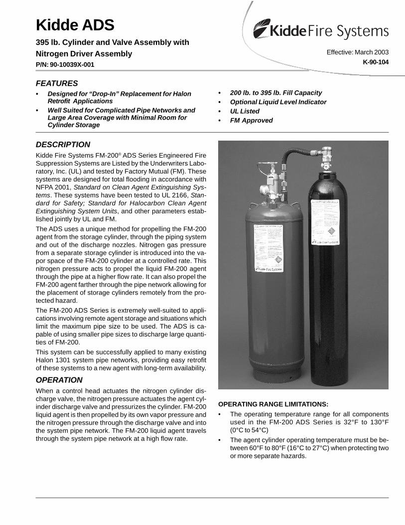
The ADS uses a unique method for propelling the FM-200agent from the storage cylinder, through the piping systemand out of the discharge nozzles. Nitrogen gas pressurefrom a separate storage cylinder is introduced into the va-por space of the FM-200 cylinder at a controlled rate. Thisnitrogen pressure acts to propel the liquid FM-200 agentthrough the pipe at a higher flow rate. It can also propel theFM-200 agent farther through the pipe network allowing forthe placement of storage cylinders remotely from the pro-tected hazard.
The FM-200 ADS Series is extremely well-suited to appli-cations involving remote agent storage and situations whichlimit the maximum pipe size to be used. The ADS is ca-pable of using smaller pipe sizes to discharge large quanti-ties of FM-200.
This system can be successfully applied to many existingHalon 1301 system pipe networks, providing easy retrofitof these systems to a new agent with long-term availability.
OPERATIONWhen a control head actuates the nitrogen cylinder dis-charge valve, the nitrogen pressure actuates the agent cyl-inder discharge valve and pressurizes the cylinder. FM-200liquid agent is then propelled by its own vapor pressure andthe nitrogen pressure through the discharge valve and intothe system pipe network. The FM-200 liquid agent travelsthrough the system pipe network at a high flow rate.
OPERATING RANGE LIMITATIONS:
• The operating temperature range for all componentsused in the FM-200 ADS Series is 32°F to 130°F(0°C to 54°C)
• The agent cylinder operating temperature must be be-tween 60°F to 80°F (16°C to 27°C) when protecting twoor more separate hazards.

TOP VIEW
1. ASSY - CYL. & VALVE ADS ASSY
2. ASSY - CYL. & VALVE NITROGEN DRIVER
5. ASSY - DISCHARGE HEAD
6. ASSY - ACTUATION
7. FITTING - ORIFICE
3. HOSE - FLEXIBLE DISCHARGE
4. STRAP - TWO CYLINDER
8. HOSE - HIGH PRESSURE
KIDDE-FENWAL
1500
PSI
0
300
600
263144
1200
900
21.75 in.(552 mm)
61.25 in.(1575 mm)
51.03 in.(1270 mm)
37.00 in.(940 mm)
65.25 in.(1659 mm)
63.22 in.(1605 mm)
58.00 in.(1473 mm)
10.50 in. Dia.(267 mm)
16.00 in. Dia.(406 mm)
19.00 in(483 mm)
395 LB. 4070 CU. IN.
FRONT VIEW
BACK VIEW
15.258 in.(382 mm)
12
4
58
6
3
7
15° 45°
Figure 1. Nitrogen and Agent Cylinders

INSTALLATIONThe FM-200 ADS Series installation is based on the require-ments of NFPA 2001, Standard on Clean Agent Extinguish-ing Systems, Current Edition.
ASSEMBLY:
Both the nitrogen driver and agent storage cylinders are tobe installed in the vertical position only. The nitrogen driveris located to the immediate right apart from the agent cylin-der (see Figure 1). The nitrogen driver cylinder is connectedto the agent cylinder by using the nitrogen transfer compo-nents (1” nitrogen transfer hose, 3/4” NPT transfer fitting,see Figure 2). The 3/4” transfer fitting connects into the ori-fice fitting. The orifice fitting is a custom fitting that is de-signed to regulate the nitrogen pressure flow required forthe specific system. The orifice fitting then connects intothe 3/4” check diffuser assembly to diffuse the nitrogen in ahorizontal pattern.
ACTUATION:
The control head is attached to the nitrogen driver by meansof electric, cable, lever, or pneumatic devices. The actuat-ing of the agent cylinder is done upon transfer of nitrogenfrom the driver cylinder using the actuation assembly kit(P/N 06-129882-001).
Assembly includes:
• Nitrogen transfer fitting
• 1/8” flex loop
• 1/8” flare fitting
• 1/8” branch tee
• 1/8” Schrader fitting and cap
• Pressure operated control head
MAINTENANCEAccording to NFPA standards, the following inspection and/or maintenance procedure must be scheduled as listed be-low and performed upon the occurrence of any event, whichmight affect the reliability of the system.
QUARTERLY:
1. Check the pressure gauge of the nitrogen driver and theweight of the agent storage container.
• Nitrogen driver if the pressure is less than 1800 PSI(124 bar) at 70°F (21°C)
Note: Pressure changes with temperature.
• The containers should be removed and carefully in-spected by certified personnel.
• The containers should then be reconditioned, re-charged or replaced.
2. Check all components supporting hardware and tighten,repair or replace as required.
3. Visually check all components for evidence of physicalwear and tear and take whatever action is required. Re-place any component that looks like it may be dam-aged or worn.
SEMI-ANNUAL:
The following checks/tests should be conducted by quali-fied personnel:
1. Determine the weight of FM-200 in each agent cylinderby the procedure indicated in the Design, Installation,Operation and Maintenance (DIOM) Manual (P/N90-FM200M-030).
2. Functional tests of required system devices (referencethe DIOM manual).
3. All outlet piping must be cleaned and free of dirt, chipsand other foreign material that may become hazardousprojectiles or cause the system to become inoperativeor ineffective at the time of discharge.
RECONDITIONING
After a system has been discharged, it is recommendedthat the local authorized Kidde Distributor be contactedto recondition the system. Please reference the DIOM manual(P/N 90-FM200M-030) for the appropriate reconditioning kit.
Figure 2. Nitrogen Transfer Components
1. FITTING - N2 TRANSFER2. VALVE - PNEUMATIC ACTUATOR3. FITTING - FLARED 1/8" X 1/4”4. HOSE - FLEXIBLE 3/16”5. TEE - 1/8" BRANCH6. VALVE - SCHRADER7. CAP - SCHRADER VALVE
2
4
3
5
6 7
1
3
Item No. Qty. P/N Description
1 1 06-236124-001 nitrogen transfer fitting
2 1 878737 pressure operated control head
3 2 06-118191-001 fitting flared 1/8" x 1/4"
4 1 06-118193-001 3/16" flexible actuation hose
5 1 06-118192-001 1/8" branch tee
6 1 WK-263303-000 1/8" Schrader valve
7 1 WK-263304-000 1/8" Schrader valve cap

This literature is provided for informational purposes only. KIDDE-FENWAL,INC. assumes noresponsibility for the product's suitability for a particular application. The product must be prop-erly applied to work correctly.If you need more information on this product, or if you have a particular problem or question,contact KIDDE-FENWAL INC., Ashland, MA 01721. Telephone: (508) 881-2000
K-90-104 03/03 Kidde-Fenwal, Inc. Printed in USA
ORDERING INFORMATIONAgent Storage Cylinder:
90-10039X-001
1: w/Liquid Level Indicator5: w/o Liquid Level Indicator
Nitrogen Driver:
90-104070-001
SPECIFICATIONS
Element
Agent Storage Container90-10039X-001
Nitrogen Driver90-104070-001
Imperial Metric Imperial Metric
Fill Range (lb. w/o LLI) 200 to 395 lb. 91 to 180 kg Factory Filled 1800 PSI Factory Filled 124 bar
Fill Range (lb. w/ LLI) 200 to 395 lb. 91 to 180 kg — —
Height 61.25 in. 155.60 cm 65.25 in. 165.70 cm
Diameter 16.0 in. 41.0 cm 10.5 in. 26.7 cm
Internal Volume 5.000 ft.3 0.142 m3 4070 cu. in. 0.0667 m3
Empty Weight 201 lb. 91.4 kg 184 lb. 83.5 kg
Temperature Range 32°F to 130°F 0°C to 54°C 32°F to 130°F 0°C to 54°C