Embed Size (px)
Citation preview

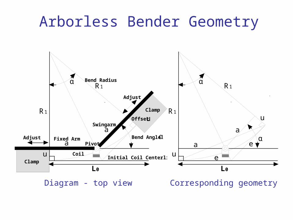
Arborless Bender
Analytical Model

Arborless Bender Geometry
α
α
e
a
R1
u
L0
a
e
R1
u
α
a
R1
u
L0
R1
u
Clamp
Clamp
Swingarm
Pivot
Bend Radius
CoilInitial Coil Centerline
Offset
Bend Angle αa
Fixed ArmAdjust
Adjust
Diagram - top view Corresponding geometry
Arborless Bender Geometry
α
α
e
a
R1
u
L0
a
e
R1
u
α
a
R1
u
L0
R1
u
Clamp
Clamp
Swingarm
Pivot
Bend Radius
CoilInitial Coil Centerline
Offset
Bend Angle αa
Fixed ArmAdjust
Adjust
Diagram - top view Corresponding geometry
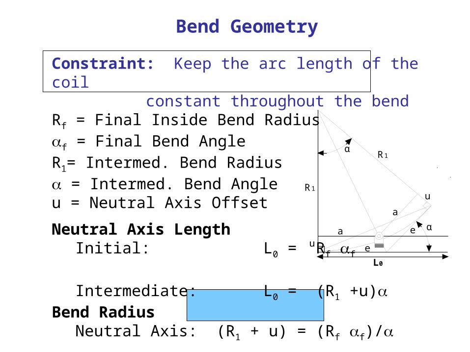
Constraint: Keep the arc length of the coil constant throughout the bend
Rf = Final Inside Bend Radiusf = Final Bend AngleR1= Intermed. Bend Radius = Intermed. Bend Angleu = Neutral Axis Offset
Neutral Axis LengthInitial: L0 = Rf f
Intermediate: L0 = (R1 +u)Bend Radius
Neutral Axis: (R1 + u) = (Rf f)/
Inside: R1 = (Rf f)/ – u
α
α
e
a
R1
u
L0
a
e
R1
u
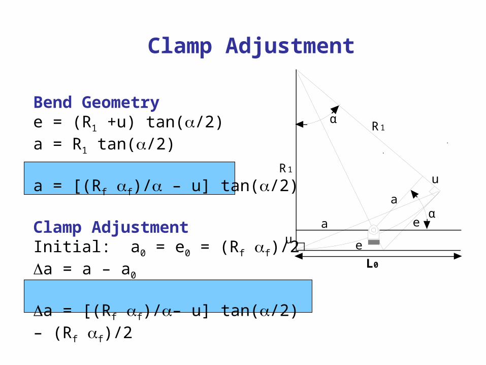
Bend Geometry
Clamp Adjustment
Bend Geometrye = (R1 +u) tan(/2)a = R1 tan(/2)
a = [(Rf f)/ – u] tan(/2)
Clamp AdjustmentInitial: a0 = e0 = (Rf f)/2a = a – a0
a = [(Rf f)/– u] tan(/2) – (Rf f)/2
α
α
e
a
R1
u
L0
a
e
R1
u
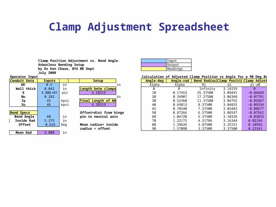
Clamp Position Adjustment vs. Bend Angle InputArborless Bending Setup Outputby Dr Ken Chase, BYU ME Dept HeadingsJuly 2008
Operator Input Calculation of Adjusted Clamp Position vs Angle for a 90 Deg BendConduit Data Inputs Setup Angle-deg Angle-rad Bend Radius Clamp Position Clamp Adjust
OD 0.5 in in Alpha Alpha R1 a1 a1-a0Wall thick 0.042 in Length betw clamps 0 0 Infinity 3.14159 0
E 3.00E+07 psi 6.28319 10 0.17453 35.37500 3.09491 -0.04668Nu 0.282 in 20 0.34907 17.37500 3.06368 -0.07791Sy 45 kpsi Final Length of NA 30 0.52360 11.37500 3.04792 -0.09367Su 48 kpsi 6.28319 40 0.69813 8.37500 3.04825 -0.09334
45 0.78540 7.37500 3.05483 -0.08677Bend Specs Offset=dist from hinge 50 0.87266 6.57500 3.06597 -0.07562
Bend Angle 60 in pin to neutral axis 60 1.04720 5.37500 3.10326 -0.03833Inside Rad 5.375 in 70 1.22173 4.51786 3.16344 0.02184
Offset 0.625 Deg Mean radius= inside 80 1.39626 3.87500 3.25151 0.10992radius + offset 90 1.57080 3.37500 3.37500 0.23341
Mean Rad 6.000 in
Clamp Adjustment Spreadsheet
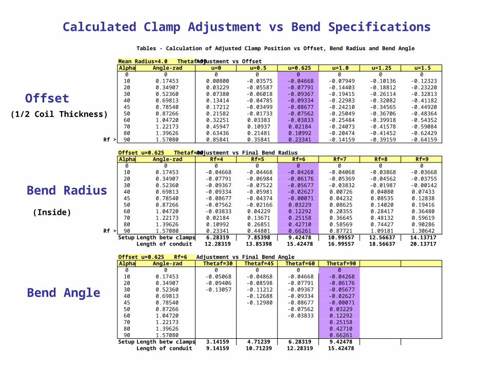
in Tables - Calculation of Adjusted Clamp Position vs Offset, Bend Radius and Bend Angledeg
Mean Radius=4.0 Thetaf=90 Adjustment vs OffsetAlpha Angle-rad u=0 u=0.5 u=0.625 u=1.0 u=1.25 u=1.5
0 0 0 0 0 0 0 010 0.17453 0.00800 -0.03575 -0.04668 -0.07949 -0.10136 -0.1232320 0.34907 0.03229 -0.05587 -0.07791 -0.14403 -0.18812 -0.2322030 0.52360 0.07380 -0.06018 -0.09367 -0.19415 -0.26114 -0.3281340 0.69813 0.13414 -0.04785 -0.09334 -0.22983 -0.32082 -0.4118245 0.78540 0.17212 -0.03499 -0.08677 -0.24210 -0.34565 -0.4492050 0.87266 0.21582 -0.01733 -0.07562 -0.25049 -0.36706 -0.4836460 1.04720 0.32251 0.03383 -0.03833 -0.25484 -0.39918 -0.5435270 1.22173 0.45947 0.10937 0.02184 -0.24073 -0.41578 -0.5908480 1.39626 0.63436 0.21481 0.10992 -0.20474 -0.41452 -0.62429
Rf >> 90 1.57080 0.85841 0.35841 0.23341 -0.14159 -0.39159 -0.64159
Offset u=0.625 Thetaf=90 Adjustment vs Final Bend RadiusAlpha Angle-rad Rf=4 Rf=5 Rf=6 Rf=7 Rf=8 Rf=9
0 0 0 0 0 0 0 010 0.17453 -0.04668 -0.04468 -0.04268 -0.04068 -0.03868 -0.0366820 0.34907 -0.07791 -0.06984 -0.06176 -0.05369 -0.04562 -0.0375530 0.52360 -0.09367 -0.07522 -0.05677 -0.03832 -0.01987 -0.0014240 0.69813 -0.09334 -0.05981 -0.02627 0.00726 0.04080 0.0743345 0.78540 -0.08677 -0.04374 -0.00071 0.04232 0.08535 0.1283850 0.87266 -0.07562 -0.02166 0.03229 0.08625 0.14020 0.1941660 1.04720 -0.03833 0.04229 0.12292 0.20355 0.28417 0.3648070 1.22173 0.02184 0.13671 0.25158 0.36645 0.48132 0.5961980 1.39626 0.10992 0.26851 0.42710 0.58569 0.74427 0.90286
Rf >> 90 1.57080 0.23341 0.44801 0.66261 0.87721 1.09181 1.30642Setup: Length betw clamps 6.28319 7.85398 9.42478 10.99557 12.56637 14.13717
Length of conduit 12.28319 13.85398 15.42478 16.99557 18.56637 20.13717
Offset u=0.625 Rf=6 Adjustment vs Final Bend AngleAlpha Angle-rad Thetaf=30 Thetaf=45 Thetaf=60 Thetaf=90
0 0 0 0 0 010 0.17453 -0.05068 -0.04868 -0.04668 -0.0426820 0.34907 -0.09406 -0.08598 -0.07791 -0.0617630 0.52360 -0.13057 -0.11212 -0.09367 -0.0567740 0.69813 -0.12688 -0.09334 -0.0262745 0.78540 -0.12980 -0.08677 -0.0007150 0.87266 -0.07562 0.0322960 1.04720 -0.03833 0.1229270 1.22173 0.2515880 1.39626 0.4271090 1.57080 0.66261
Setup: Length betw clamps 3.14159 4.71239 6.28319 9.42478Length of conduit 9.14159 10.71239 12.28319 15.42478
Offset
Bend Radius
Bend Angle
Calculated Clamp Adjustment vs Bend Specifications
(1/2 Coil Thickness)
(Inside)
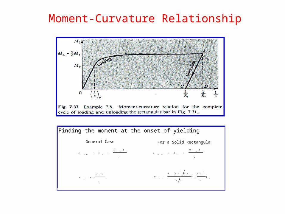
Moment-Curvature Relationship
Finding the moment at the onset of yielding
( )
Y
Y
Y
S
b h
h
b hS
M
62
1 223
==
c
IS
MY
Y
=
I
cM
SY
Y==
m a xσ
I
cM
SY
Y==
m a xσ
General Case For a Solid Rectangular Bar
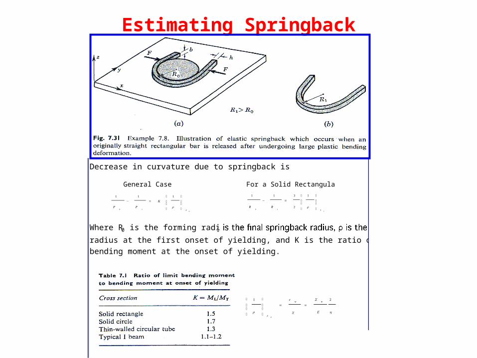
Estimating Springback
Decrease in curvature due to springback is
Where R0 is the forming radius, R1radius at the first onset of yielding, and K is the ratio of limit bending to bending moment at the onset of yielding.
YS
RR⎟⎟
⎠
⎞
⎜⎜
⎝
⎛
=−
ρ
1
2
311
10
hE
S
c
YY
SY
21
==⎟⎟
⎠
⎞
⎜⎜
⎝
⎛ ε
ρ
YS
K
RR⎟⎟
⎠
⎞
⎜⎜
⎝
⎛
=−
ρ
111
10
General Case For a Solid Rectangular Bar
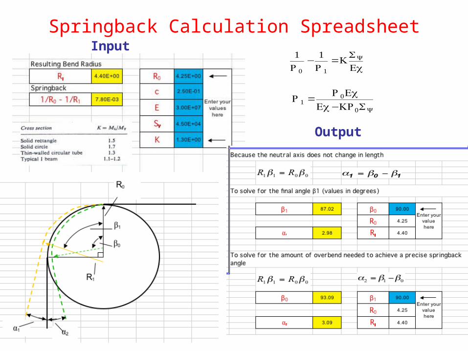
Springback Calculation SpreadsheetInput
Output
€
1R0
− 1R1
=KSY
Ec
€
R1 =R0Ec
Ec−KR0SY