Embed Size (px)
Citation preview
COMPACT BENDERFlOOR
38470ASSEMBlY INSTRUCTIONS & PROJECT IDEAS
Rev 08/00
Diagrams within this manual may not be drawn proportionally.Due to continuing improvements, actual product may differ slightly from the product described herein.
Distributed exclusively by Harbor Freight Tools®.3491 Mission Oaks Blvd., Camarillo, CA 93011
Visit our website at: http://www.harborfreight.com
Read this material before using this product. Failure to do so can result in serious injury. SaVe THiS manual.
Copyright© 2000 by Harbor Freight Tools®. All rights reserved. No portion of this manual or any artwork contained herein may be reproduced in any shape or form without the express written consent of Harbor Freight Tools.
For technical questions or replacement parts, please call 1-800-444-3353.
THANK YOU for choosing a HARBOR FREIGHT TOOlS product. For future reference, please complete the owner’s record below:
Model___________ Serial No._____________ Purchase Date_____________
Save This manualYou will need the manual for the safety warnings and precautions, assembly instructions, operatingand maintenance procedures, parts list and diagram. Keep your invoice with this manual. Write the invoice number on the inside of the front cover. Keep the manual and invoice in a safe and dry place for future reference.
Technical Specifications
Tool Name: Compact Bender-Floor Item Number: 38470 Dimensions: 10-1/8” W x 39-3/4”H x 35-3/4”l Stand: .325” Steel Mounting Holes: (4) ½” Max. Width of Stock: 1-15/16” Max. Stock Thickness: 5/16” Max. Bar Stock Diameter: 5/8” Dies: 1”, 1-1/4”, 1-1/2”, 1-3/4”, 2”, 2-1/2”, 3” Tool Weight: 44 lBS.
Safety Warnings and PrecautionsWaRninG: When using tool, basic safety precautions should always be followed to reduce the risk of personal injury and damage to equipment.
Read all instructions before using this product!1. avoid working alone. If an accident happens, an assistant can bring help.
2. Keep work area clean. Cluttered areas invite injuries.
3. Observe work area conditions. Keep work area well lighted.
4. Keep children away. Children must never be allowed in the work area. Do not let them handle machines, tools, or extension cords.
5. Store idle equipment. When not in use, tools must be stored in a dry location to inhibit rust. Always lock up tools and keep out of reach of children.
6. Dress properly. Do not wear loose clothing or jewelry as they can be caught in moving parts. Protective, electrically nonconductive clothes and nonskid footwear are recommended when working. Wear restrictive hair covering to contain long hair.
7. use eye and ear protection. Always wear ANSI approved impact safety goggles.
8. Do not overreach. Keep proper footing and balance at all times.
#38470 Page 2
9. use the right tool for the job. Do not attempt to force a small tool or attachment to do the work of a larger industrial tool. There are certain applications for which this tool was designed. Do not modify this tool and do not use this tool for a purpose for which it was not intended.
10. Stay alert. Watch what you are doing, use common sense. Do not operate any tool when you are tired.
11. Check for damaged parts. Before using any tool, any part that appears damaged should be carefully checked to determine that it will operate properly and perform its intended function. Check for alignment and binding of moving parts; any broken parts or mounting fixtures; and any other condition that may affect proper operation. Any part that is damaged should be properly repaired or replaced by a qualified technician. Do not use the tool if any switch does not turn On and Off properly.
12. Replacement parts and accessories. When servicing, use only identical replacement parts. Use of any other parts will void the warranty. Only use accessories intended for use with this tool. Approved accessories are available from Harbor Freight Tools.
13. Do not operate tool if under the influence of alcohol or drugs. Read warning labels on prescriptions to determine if your judgment or reflexes are impaired while taking drugs. If there is any doubt, do not operate the tool.
14. maintenance. For your safety, maintenance should be performed regularly by a qualified technician.
Warning: The warnings, cautions, and instructions discussed in this instruction manual cannot cover all possible conditions and situations that may occur. it must be understood by the operator that common sense and caution are factors which cannot be built into this product, but must be supplied by the operator.
WaRninG: WelDinG PReCauTiOnSif you perform any welding using the materials that have been bent by this tool, it is important that you remember that there are additional safety precautions that must be taken. Of course, you should follow all warnings and instructions provided by the manufacturer of the welding equipment used.
Be aware of flying sparks. Only weld in an area that does not contain any materials which can be ignited by flying sparks. Extinguish any significant flying sparks before continuing to weld.
Protect yourself and others around you from burns which can be caused by flying sparks.
Make certain that you have a fire extinguisher accessible.
Never weld in an atmosphere which might contain flammable fumes.
Periodically during welding, and after completion of a job, inspect your area for any ignition which may have been caused by flying sparks.
Never leave your welder unattended while it is plugged in.
Always wear electrical insulating clothing, gloves and shoes while using your welder.
Flying sparks can cause injury, and hot materials can cause burns. Please wear appropriate safety clothing, and observe precautions to prevent burns or injury to yourself or others.
Wear protective clothing such as heavy gloves, apron and boots.
Do not look directly into the welding arc without appropriate protective eye shields.
Do not allow others to look directly into the arc without appropriate eye protection.
Wear protective gloves while welding. Welding causes the metal to become very hot, which can cause burns. Do not touch welded areas until you are certain they have completely cooled.
#38470 Page 3
WaRninG: WelDinG PReCauTiOnS (Continued)
The electrode, and especially the welding rods become very hot during welding. Exercise extreme caution to prevent burns to yourself or others.
nOTe: Read and adhere to all warnings and instructions in the instruction manual provided by the manufacturer of the welder being used.
assembly
Your Compact Bender-Floor will require complete assembly prior to operation. It is important that you read the entire manual to become familiar with the unit BEFORE you use the Compact Bender. Before assembling your Compact Bender be sure that you have all parts described in the Parts list on page 9.
When assembling your Compact Bender-Floor, it will be helpful to refer to each of the operational Figures as well as to the Parts list and Assembly Diagrams on pages 9-11.
Mounting Surface: The mounting surface must be flat, level and capable of supporting the weight of theCompact Bender combined with the materials to be worked with.
Step 1) Bolt the Stand (#11) to a flat, stable floor surface that is capable of supporting the weight of this tool and the various workpieces to be used.
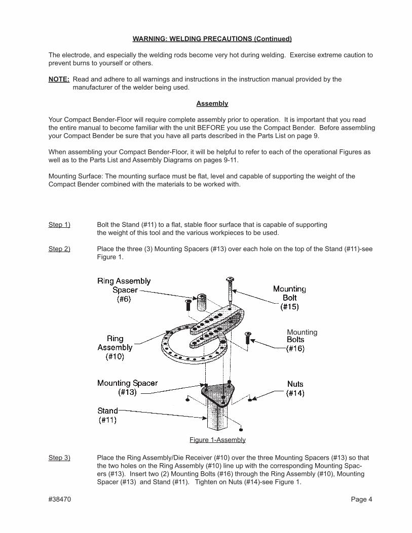
Step 2) Place the three (3) Mounting Spacers (#13) over each hole on the top of the Stand (#11)-see Figure 1.
Mounting
Figure 1-Assembly
Step 3) Place the Ring Assembly/Die Receiver (#10) over the three Mounting Spacers (#13) so that the two holes on the Ring Assembly (#10) line up with the corresponding Mounting Spac-ers (#13). Insert two (2) Mounting Bolts (#16) through the Ring Assembly (#10), Mounting Spacer (#13) and Stand (#11). Tighten on Nuts (#14)-see Figure 1.
#38470 Page 4
Step 4) Place the Ring Assembly Spacer (#6) inside the arms of the Ring Assembly/Die Receiver (#10) between the back two holes-see Figure 1. Insert the Mounting Bolt (#15) through the Ring Assembly/Die Receiver (#10), through the Ring Assembly Spacer (#6) and through the bottom hole in the Ring Assembly/Die Receiver. Tighten it into place with the remaining Nut (#14).
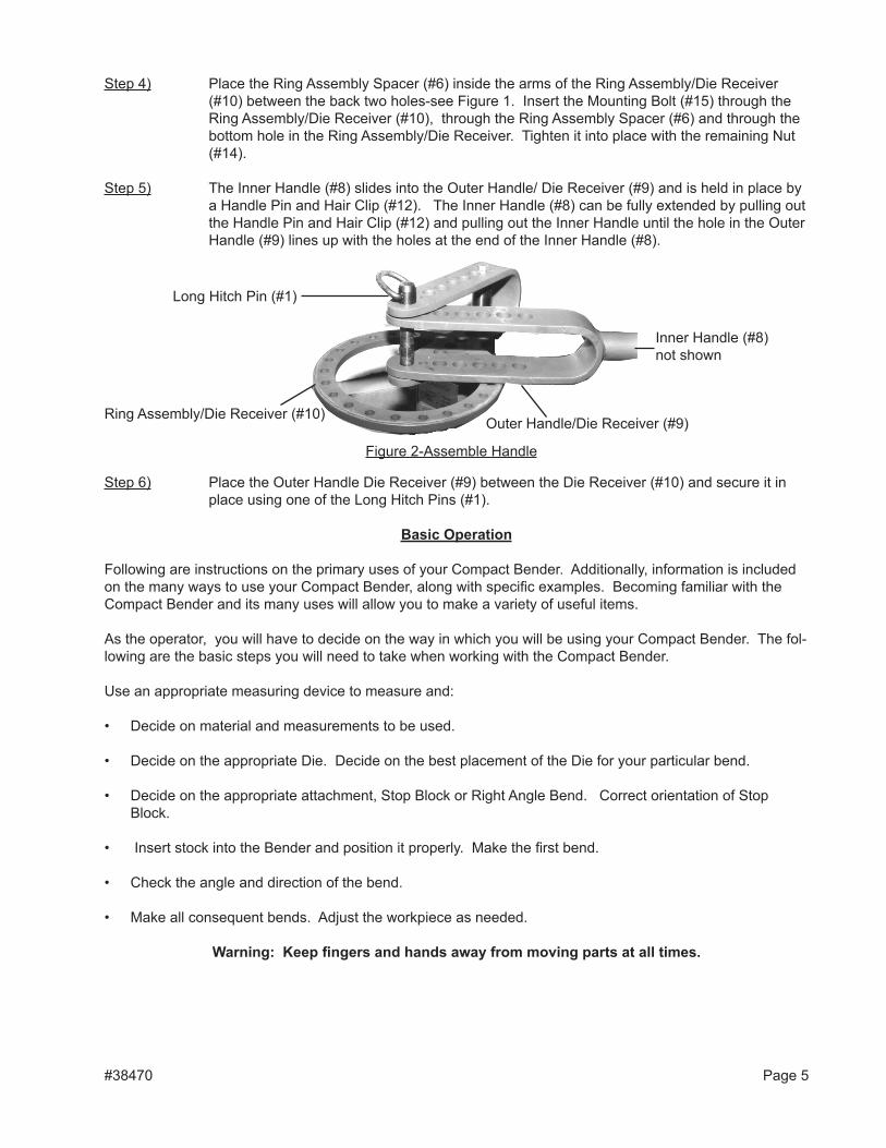
Step 5) The Inner Handle (#8) slides into the Outer Handle/ Die Receiver (#9) and is held in place by a Handle Pin and Hair Clip (#12). The Inner Handle (#8) can be fully extended by pulling out the Handle Pin and Hair Clip (#12) and pulling out the Inner Handle until the hole in the Outer Handle (#9) lines up with the holes at the end of the Inner Handle (#8).
Figure 2-Assemble Handle
Ring Assembly/Die Receiver (#10)
long Hitch Pin (#1)
Outer Handle/Die Receiver (#9)
Inner Handle (#8) not shown
Step 6) Place the Outer Handle Die Receiver (#9) between the Die Receiver (#10) and secure it in place using one of the long Hitch Pins (#1).
Basic Operation
Following are instructions on the primary uses of your Compact Bender. Additionally, information is included on the many ways to use your Compact Bender, along with specific examples. Becoming familiar with the Compact Bender and its many uses will allow you to make a variety of useful items.
As the operator, you will have to decide on the way in which you will be using your Compact Bender. The fol-lowing are the basic steps you will need to take when working with the Compact Bender.
Use an appropriate measuring device to measure and:
• Decide on material and measurements to be used.
• Decide on the appropriate Die. Decide on the best placement of the Die for your particular bend.
• Decide on the appropriate attachment, Stop Block or Right Angle Bend. Correct orientation of Stop Block.
• Insert stock into the Bender and position it properly. Make the first bend.
• Check the angle and direction of the bend.
• Make all consequent bends. Adjust the workpiece as needed.
Warning: Keep fingers and hands away from moving parts at all times.
#38470 Page 5
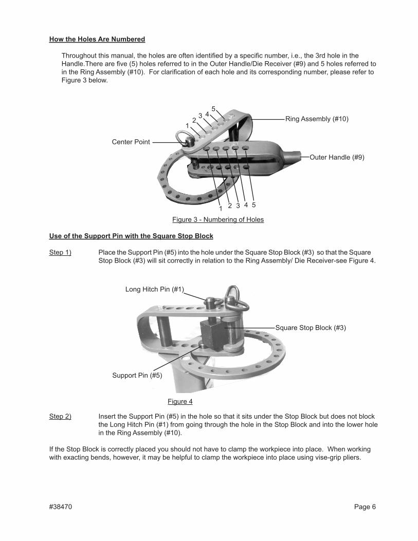
How the Holes are numbered
Throughout this manual, the holes are often identified by a specific number, i.e., the 3rd hole in the Handle.There are five (5) holes referred to in the Outer Handle/Die Receiver (#9) and 5 holes referred to in the Ring Assembly (#10). For clarification of each hole and its corresponding number, please refer to Figure 3 below.
use of the Support Pin with the Square Stop Block
Step 1) Place the Support Pin (#5) into the hole under the Square Stop Block (#3) so that the Square Stop Block (#3) will sit correctly in relation to the Ring Assembly/ Die Receiver-see Figure 4.
Step 2) Insert the Support Pin (#5) in the hole so that it sits under the Stop Block but does not block the long Hitch Pin (#1) from going through the hole in the Stop Block and into the lower hole in the Ring Assembly (#10).
If the Stop Block is correctly placed you should not have to clamp the workpiece into place. When working with exacting bends, however, it may be helpful to clamp the workpiece into place using vise-grip pliers.
#38470 Page 6
12
3 45
1 2 3 4 5
Center Point
Outer Handle (#9)
Ring Assembly (#10)
Figure 3 - Numbering of Holes
long Hitch Pin (#1)
Support Pin (#5)
Square Stop Block (#3)
Figure 4
Placement of Die
Dies are placed at one or two different locations depending on the bend to be made:
• A die can be used in conjunction with the Short Hitch Pin (#2) at the intersection of the Outer Handle/Die Receiver (#9) and the Ring Assembly/Die Receiver (#10).
• The Die can also be placed on the Outer Handle/Die Receiver (#9).
• Two Dies can be placed so that one is on the Outer Handle/Die Receiver (#9) and one at the center point where the Outer Handle/Die Receiver (#9) and Ring Assembly/Die Receiver (#10) intersect-see Figure 3.
Orientation of the Handle
The Handle is always oriented up and on the right side. The Handle is always moved clockwise when a bend is being made.
use of the Square Stop Block
The Stop Block is so named because it stops the workpiece from turning while the workpiece is being bent, thus “stopping” movement of the workpiece.
When bending your workpiece, place the Square Stop Block (#3) over one of the holes in the Ring Assembly/Die Receiver (#10). You will have to do some testing to determine placement of the Square Stop Block. You will need to place it over the appropriate hole for the bend you desire and the Die you are using.
Step 1) There are four (4) key positions to place the Square Stop Block (#3) in while bending. The four positions (as seen from looking down on the top of the Square Stop Block) are identified in this manual by a letter; A, B, C, or D. See Figure 5 on the next page, for the letter and the corresponding position of the Square Stop Block.
Warning: Always position the Stop Block so that it’s hole is oriented to the right side. Even though another side of the Stop Block may actually face the work piece. If the hole is oriented left instead of right, this will result in the Stop Block turning which will cause the workpiece to move.
Step 2) Set the appropriate Die into place on the Outer Handle/Die Receiver (#9) between the upper and lower fork. Secure the Die in place by inserting the Short Hitch Pin (#2) through the Outer Handle/Die Receiver (#9) and the Square Stop Block. The Square Stop Block (#3) is held in place against the stock as shown in Figure 7 on page 12.
Step 3) Set your workpiece into position. With the Handle (#9) in the starting position, set the Square Stop Block (#3) as close to the long Hitch Pin (#1) at the center position, as possible.
note: To avoid large spaces between the Stop Block, the Center Pin and selected Die, orient the Square Stop Block differently, or if possible, move it one hole closer to center.
#38470 Page 7
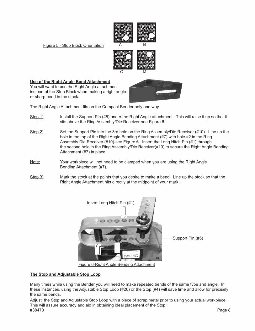
use of the Right angle Bend attachmentYou will want to use the Right Angle attachment instead of the Stop Block when making a right angle or sharp bend in the stock.
The Right Angle Attachment fits on the Compact Bender only one way.
Step 1) Install the Support Pin (#5) under the Right Angle attachment. This will raise it up so that it sits above the Ring Assembly/Die Receiver-see Figure 6.
Step 2) Set the Support Pin into the 3rd hole on the Ring Assembly/Die Receiver (#10). line up the hole in the top of the Right Angle Bending Attachment (#7) with hole #2 in the Ring Assembly Die Receiver (#10)-see Figure 6. Insert the long Hitch Pin (#1) through the second hole in the Ring Assembly/Die Receiver(#10) to secure the Right Angle Bending Attachment (#7) in place. Note: Your workpiece will not need to be clamped when you are using the Right Angle Bending Attachment (#7).
Step 3) Mark the stock at the points that you desire to make a bend. line up the stock so that the Right Angle Attachment hits directly at the midpoint of your mark.
A B
C D
Figure 5 - Stop Block Orientation
Support Pin (#5)
Figure 6-Right Angle Bending Attachment
#38470 Page 8
Insert long Hitch Pin (#1)
The Stop and adjustable Stop loop
Many times while using the Bender you will need to make repeated bends of the same type and angle. In these instances, using the Adjustable Stop loop (#26) or the Stop (#4) will save time and allow for precisely the same bends.Adjust the Stop and Adjustable Stop loop with a piece of scrap metal prior to using your actual workpiece. This will assure accuracy and aid in obtaining ideal placement of the Stop.
Stop
Step 1) Test and decide the amount and distance of Handle rotation to make the desired bend.
Step 2) Place the Stop (#4) into the next hole (clockwise) after your rotation is complete.
adjustable Stop loop
Use the Adjustable Stop Loop (#26) for stops where a finer adjustment is needed. The Adjustable Stop Loop allows for more precise stops as it can be adjusted whereas the Stop (#4) is simply placed into a hole on the Ring.
Step 1) Test and decide the amount and distance of Handle rotation to make the desired bend.
Step 2) Place the Adjustable Stop loop (#26) directly at the point where the rotation of the Handle is to end. Insert Mounting Bolt (#25) through 3/8” Washer (#24) to hold the Adjustable Stop loop in place. Tighten on Washer (#24) and Nut (#27).
Step 3) Try a test bend and adjust the Adjustable Stop loop (#26) as necessary to obtain a precise bend.
Now that the basic operating instructions have been described; it is time to practice using the Compact Bender. We are going to show you how to make several useful items such as handles and anchor bolts. We will also show you how to make letters of the alphabet for use in making decorative signs. Once you practice on the Compact Bender and learn its capabilities, it should be easy to come up with additional uses for the Compact Bender based on your interests and work requirements..
unpacking
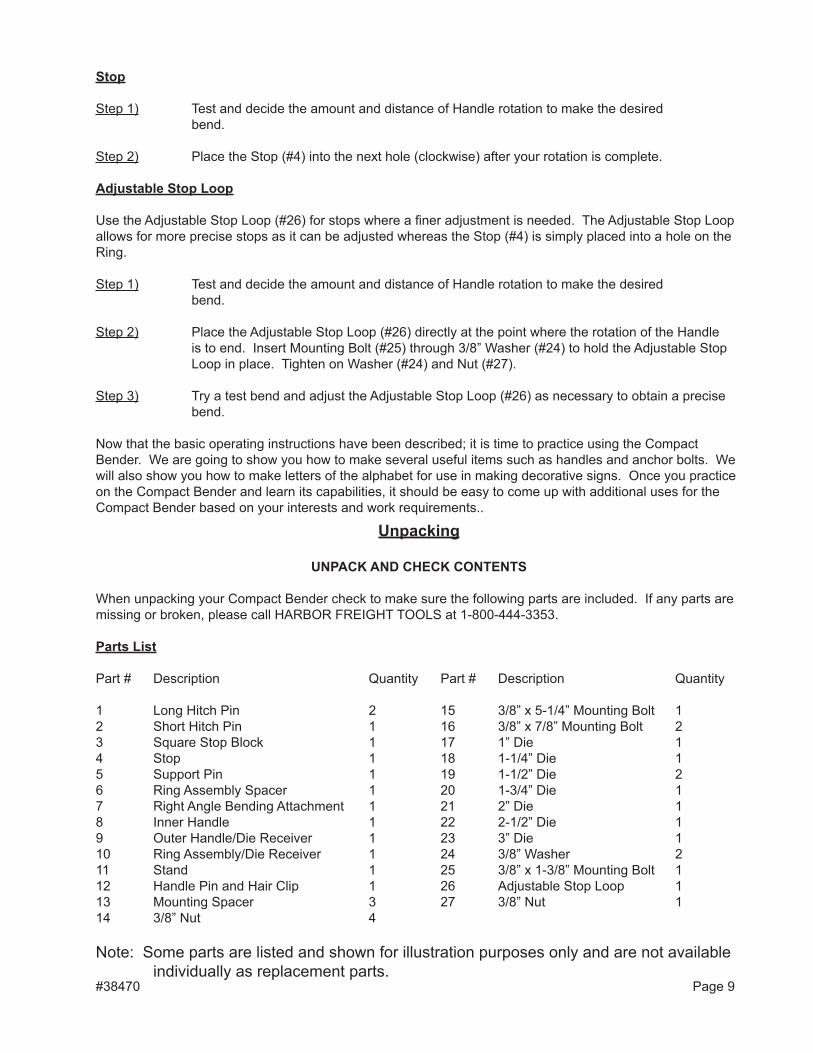
unPaCK anD CHeCK COnTenTS
When unpacking your Compact Bender check to make sure the following parts are included. If any parts are missing or broken, please call HARBOR FREIGHT TOOlS at 1-800-444-3353.
Parts list
Part # Description Quantity Part # Description Quantity
1 long Hitch Pin 2 15 3/8” x 5-1/4” Mounting Bolt 1 2 Short Hitch Pin 1 16 3/8” x 7/8” Mounting Bolt 2 3 Square Stop Block 1 17 1” Die 1 4 Stop 1 18 1-1/4” Die 1 5 Support Pin 1 19 1-1/2” Die 2 6 Ring Assembly Spacer 1 20 1-3/4” Die 1 7 Right Angle Bending Attachment 1 21 2” Die 1 8 Inner Handle 1 22 2-1/2” Die 1 9 Outer Handle/Die Receiver 1 23 3” Die 1 10 Ring Assembly/Die Receiver 1 24 3/8” Washer 2 11 Stand 1 25 3/8” x 1-3/8” Mounting Bolt 1 12 Handle Pin and Hair Clip 1 26 Adjustable Stop loop 1 13 Mounting Spacer 3 27 3/8” Nut 1 14 3/8” Nut 4
Note: Some parts are listed and shown for illustration purposes only and are not available individually as replacement parts. #38470 Page 9
10
PleaSe ReaD THe FOllOWinG CaReFullY
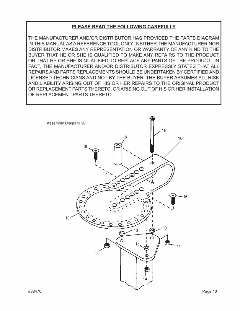
THE MANUFACTURER AND/OR DISTRIBUTOR HAS PROVIDED THE PARTS DIAGRAM IN THIS MANUAl AS A REFERENCE TOOl ONlY. NEITHER THE MANUFACTURER NOR DISTRIBUTOR MAKES ANY REPRESENTATION OR WARRANTY OF ANY KIND TO THE BUYER THAT HE OR SHE IS QUAlIFIED TO MAKE ANY REPAIRS TO THE PRODUCT OR THAT HE OR SHE IS QUAlIFIED TO REPlACE ANY PARTS OF THE PRODUCT. IN FACT, THE MANUFACTURER AND/OR DISTRIBUTOR EXPRESSlY STATES THAT All REPAIRS AND PARTS REPlACEMENTS SHOUlD BE UNDERTAKEN BY CERTIFIED AND lICENSED TECHNICIANS AND NOT BY THE BUYER. THE BUYER ASSUMES All RISK AND lIABIlITY ARISING OUT OF HIS OR HER REPAIRS TO THE ORIGINAl PRODUCT OR REPlACEMENT PARTS THERETO, OR ARISING OUT OF HIS OR HER INSTAllATION OF REPlACEMENT PARTS THERETO.
Assembly Diagram “A”
#38470 Page 10
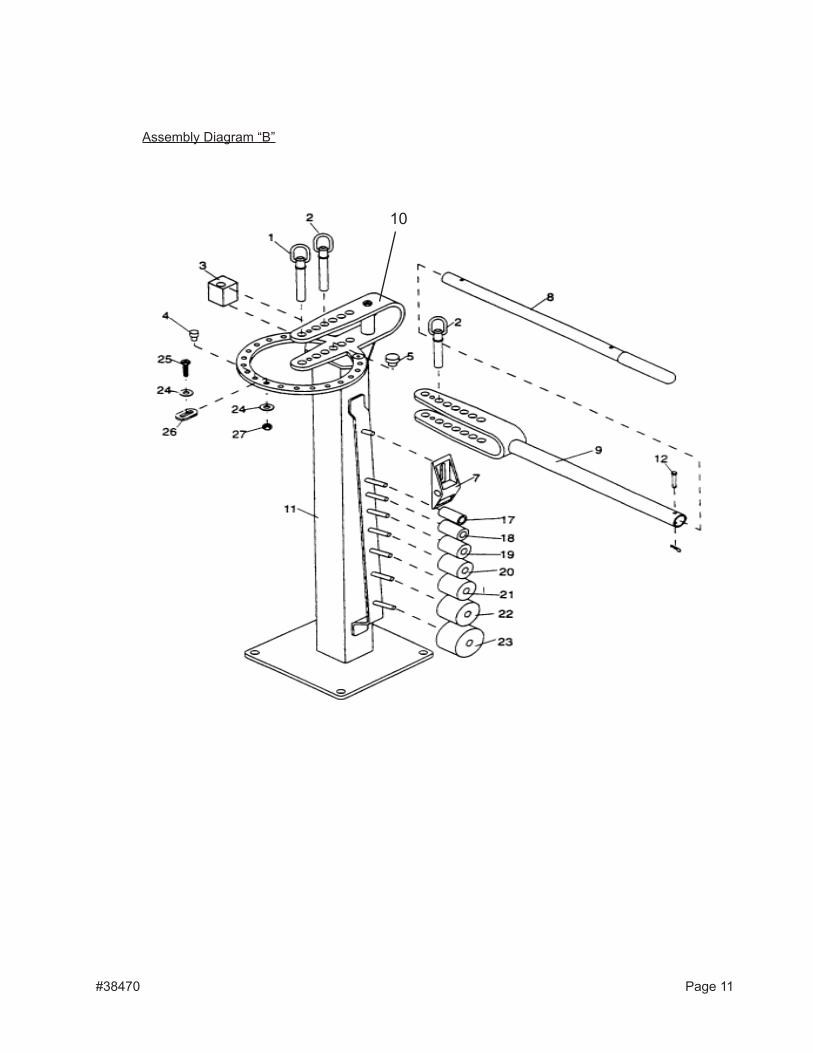
Assembly Diagram “B”
#38470 Page 11
10
MAKING HANDlES
Round Stock
To make handles using round stock, the Square Stop Block (#3) is used rather than the Right Angle Attachment.
Use a 10” piece of 5/8” round stock and two sections of flat stock for the ends. The measurements given are general guides only. Measurements should be adjusted according to your preferences and specific needs. If changing stock size, you will have to experiment to obtain the best points for each bend.
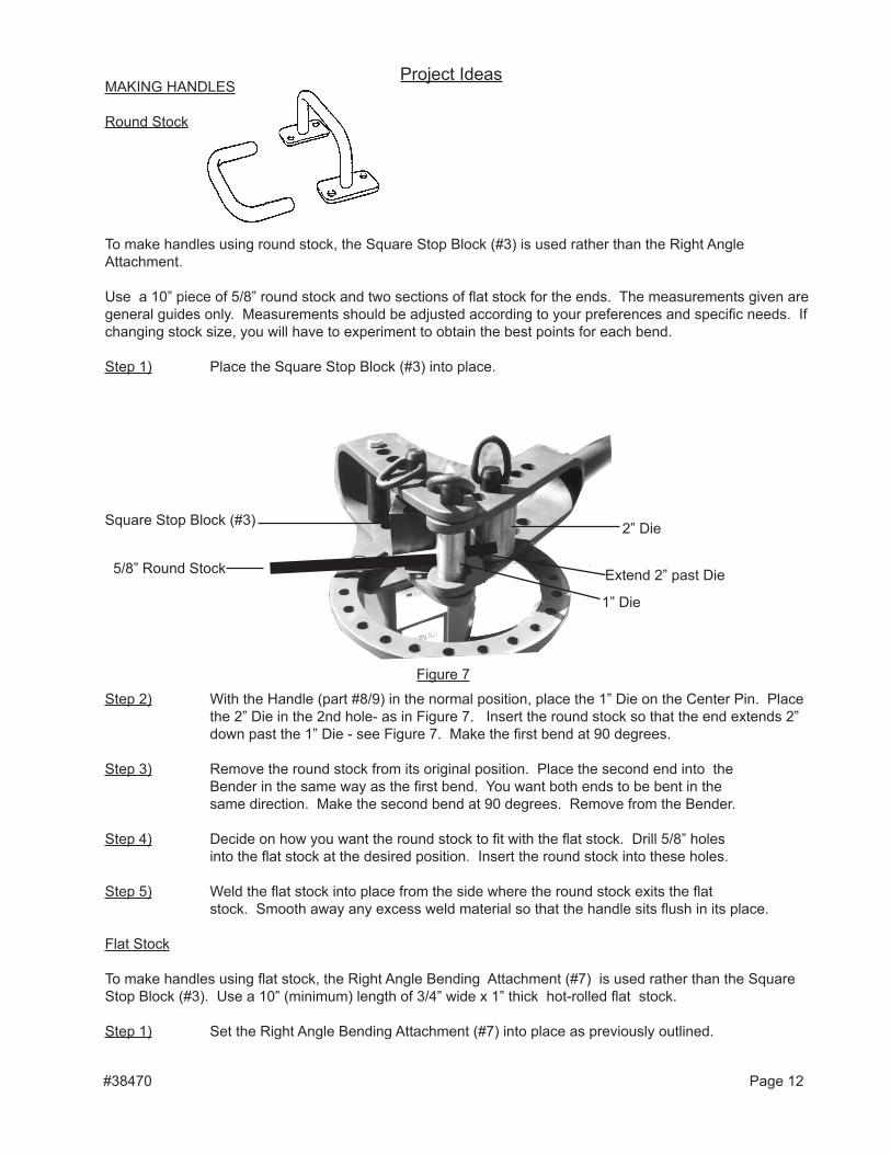
Step 1) Place the Square Stop Block (#3) into place.
Step 2) With the Handle (part #8/9) in the normal position, place the 1” Die on the Center Pin. Place the 2” Die in the 2nd hole- as in Figure 7. Insert the round stock so that the end extends 2” down past the 1” Die - see Figure 7. Make the first bend at 90 degrees.
Step 3) Remove the round stock from its original position. Place the second end into the Bender in the same way as the first bend. You want both ends to be bent in the same direction. Make the second bend at 90 degrees. Remove from the Bender.
Step 4) Decide on how you want the round stock to fit with the flat stock. Drill 5/8” holes into the flat stock at the desired position. Insert the round stock into these holes.
Step 5) Weld the flat stock into place from the side where the round stock exits the flat stock. Smooth away any excess weld material so that the handle sits flush in its place.
Flat Stock
To make handles using flat stock, the Right Angle Bending Attachment (#7) is used rather than the Square Stop Block (#3). Use a 10” (minimum) length of 3/4” wide x 1” thick hot-rolled flat stock.
Step 1) Set the Right Angle Bending Attachment (#7) into place as previously outlined.
#38470 Page 12
Square Stop Block (#3)
1” Die
Extend 2” past Die
2” Die
Figure 7
5/8” Round Stock
Project Ideas
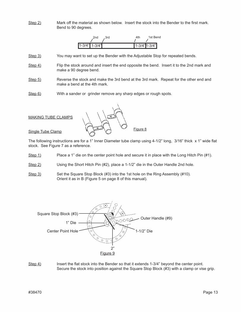
Step 2) Mark off the material as shown below. Insert the stock into the Bender to the first mark. Bend to 90 degrees.
Step 3) You may want to set up the Bender with the Adjustable Stop for repeated bends.
Step 4) Flip the stock around and insert the end opposite the bend. Insert it to the 2nd mark and make a 90 degree bend.
Step 5) Reverse the stock and make the 3rd bend at the 3rd mark. Repeat for the other end and make a bend at the 4th mark.
Step 6) With a sander or grinder remove any sharp edges or rough spots.
MAKING TUBE ClAMPS
Single Tube Clamp
The following instructions are for a 1” Inner Diameter tube clamp using 4-1/2” long, 3/16” thick x 1” wide flat stock. See Figure 7 as a reference.
Step 1) Place a 1” die on the center point hole and secure it in place with the long Hitch Pin (#1).
Step 2) Using the Short Hitch Pin (#2), place a 1-1/2” die in the Outer Handle 2nd hole.
Step 3) Set the Square Stop Block (#3) into the 1st hole on the Ring Assembly (#10). Orient it as in B (Figure 5 on page 8 of this manual).
Step 4) Insert the flat stock into the Bender so that it extends 1-3/4” beyond the center point. Secure the stock into position against the Square Stop Block (#3) with a clamp or vise grip.
#38470 Page 13
Square Stop Block (#3)
1” Die
Center Point Hole
2”
1-1/2” Die
Outer Handle (#9)
Figure 9
1-3/4” 1-3/4”1-3/4” 1-3/4”
1st Bend2nd 3rd 4th
Figure 8
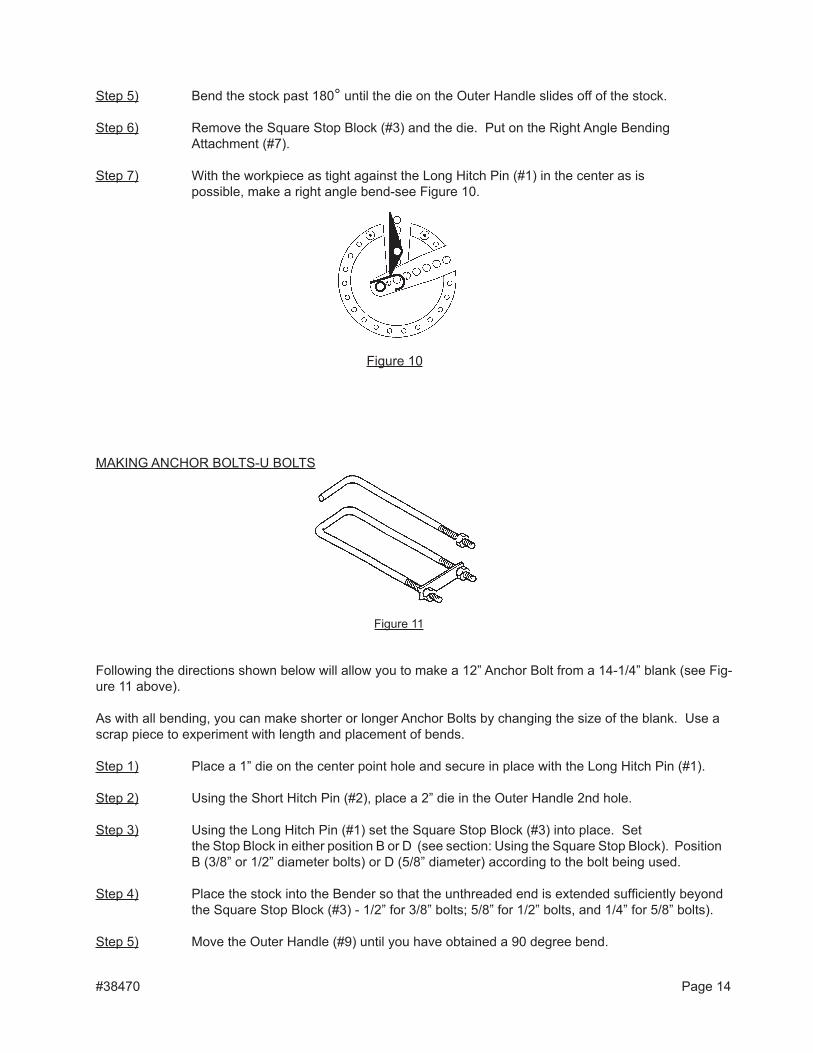
Step 5) Bend the stock past 180° until the die on the Outer Handle slides off of the stock.
Step 6) Remove the Square Stop Block (#3) and the die. Put on the Right Angle Bending Attachment (#7).
Step 7) With the workpiece as tight against the long Hitch Pin (#1) in the center as is possible, make a right angle bend-see Figure 10.
MAKING ANCHOR BOlTS-U BOlTS
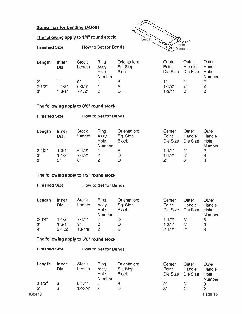
Following the directions shown below will allow you to make a 12” Anchor Bolt from a 14-1/4” blank (see Fig-ure 11 above).
As with all bending, you can make shorter or longer Anchor Bolts by changing the size of the blank. Use a scrap piece to experiment with length and placement of bends.
Step 1) Place a 1” die on the center point hole and secure in place with the long Hitch Pin (#1).
Step 2) Using the Short Hitch Pin (#2), place a 2” die in the Outer Handle 2nd hole.
Step 3) Using the long Hitch Pin (#1) set the Square Stop Block (#3) into place. Set the Stop Block in either position B or D (see section: Using the Square Stop Block). Position B (3/8” or 1/2” diameter bolts) or D (5/8” diameter) according to the bolt being used.
Step 4) Place the stock into the Bender so that the unthreaded end is extended sufficiently beyond the Square Stop Block (#3) - 1/2” for 3/8” bolts; 5/8” for 1/2” bolts, and 1/4” for 5/8” bolts).
Step 5) Move the Outer Handle (#9) until you have obtained a 90 degree bend.
Figure 10
#38470 Page 14
Figure 11
#38470 Page 15
length
Inner Diameter
limiTeD 90 DaY WaRRanTYHarbor Freight Tools Co. makes every effort to assure that its products meet high quality
and durability standards, and warrants to the original purchaser that this product is free from defects in materials and workmanship for the period of 90 days from the date of purchase. This warranty does not apply to damage due directly or indirectly, to misuse, abuse, negligence or accidents, repairs or alterations outside our facilities, criminal activity, improper installation, normal wear and tear, or to lack of maintenance. We shall in no event be liable for death, in-juries to persons or property, or for incidental, contingent, special or consequential damages arising from the use of our product. Some states do not allow the exclusion or limitation of incidental or consequential damages, so the above limitation of exclusion may not apply to you. THIS WARRANTY IS EXPRESSlY IN lIEU OF All OTHER WARRANTIES, EXPRESS OR IMPlIED, INClUDING THE WARRANTIES OF MERCHANTABIlITY AND FITNESS.
To take advantage of this warranty, the product or part must be returned to us with transportation charges prepaid. Proof of purchase date and an explanation of the complaint must accompany the merchandise. If our inspection verifies the defect, we will either repair or replace the product at our election or we may elect to refund the purchase price if we cannot readily and quickly provide you with a replacement. We will return repaired products at our expense, but if we determine there is no defect, or that the defect resulted from causes not within the scope of our warranty, then you must bear the cost of returning the product.
This warranty gives you specific legal rights and you may also have other rights which vary from state to state.
3491 Mission Oaks Blvd. • PO Box 6009 • Camarillo, CA 93011 • (800) 444-3353
#38470 Page 16
MAKING INDIVIDUAl lETTERS OF THE AlPHABET
Directions and tips for creating each letter of the alphabet areincluded in the following section. The information given is based on use of 3/16” flat stock, and a 1” max. width. The letters created by using these steps are six (6”) high and 1” deep.
When creating each letter make certain that you use hot-rolled mild steel. Aluminum can also be used.
The steps are fairly precise, but as with all bending functions you may create you own unique designs and measurements through trial and error. Use a scrap piece of metal for practice prior to creating the actual workpiece.
Use a protractor to measure each angle.
To make the following letters use the Right Angle Bend Attachment (#7) for each bend.
Tip: Always double check the measurements on each angle you bend.
Note: Use the Stop or Adjustable Stop for repeated bends at the same angle.
Note: After each letter has been formed, smooth away any sharp edges using a grinder or by sanding.
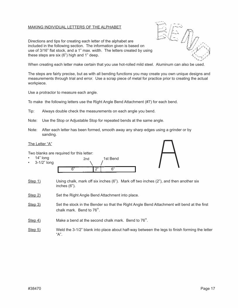
The letter “A”
Two blanks are required for this letter:• 14” long• 3-1/2” long
Step 1) Using chalk, mark off six inches (6”). Mark off two inches (2”), and then another six inches (6”).
Step 2) Set the Right Angle Bend Attachment into place.
Step 3) Set the stock in the Bender so that the Right Angle Bend Attachment will bend at the first chalk mark. Bend to 76°.
Step 4) Make a bend at the second chalk mark. Bend to 76°.
Step 5) Weld the 3-1/2” blank into place about half-way between the legs to finish forming the letter “A”.
#38470 Page 17
6” 6”2”
1st Bend2nd
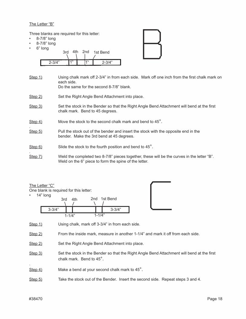
The letter “B”
Three blanks are required for this letter:• 8-7/8” long• 8-7/8” long• 6” long
Step 1) Using chalk mark off 2-3/4” in from each side. Mark off one inch from the first chalk mark on each side.
Do the same for the second 8-7/8” blank.
Step 2) Set the Right Angle Bend Attachment into place.
Step 3) Set the stock in the Bender so that the Right Angle Bend Attachment will bend at the first chalk mark. Bend to 45 degrees.
Step 4) Move the stock to the second chalk mark and bend to 45°.. Step 5) Pull the stock out of the bender and insert the stock with the opposite end in the
bender. Make the 3rd bend at 45 degrees.
Step 6) Slide the stock to the fourth position and bend to 45°.. Step 7) Weld the completed two 8-7/8” pieces together, these will be the curves in the letter “B”. Weld on the 6” piece to form the spine of the letter.
The letter “C”One blank is required for this letter:• 14” long
Step 1) Using chalk, mark off 3-3/4” in from each side.
Step 2) From the inside mark, measure in another 1-1/4” and mark it off from each side.
Step 2) Set the Right Angle Bend Attachment into place.
Step 3) Set the stock in the Bender so that the Right Angle Bend Attachment will bend at the first chalk mark. Bend to 45°.
. Step 4) Make a bend at your second chalk mark to 45°.
Step 5) Take the stock out of the Bender. Insert the second side. Repeat steps 3 and 4.
#38470 Page 18
1st Bend2nd3rd 4th
3-3/4” 3-3/4”1-1/4”
1st Bend2nd3rd 4th
2-3/4” 2-3/4”1”1”
1-1/4”
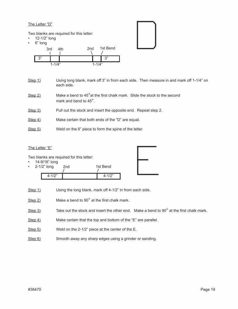
The letter “D”
Two blanks are required for this letter:• 12-1/2” long• 6” long
Step 1) Using long blank, mark off 3” in from each side. Then measure in and mark off 1-1/4” on each side.
Step 2) Make a bend to 45°at the first chalk mark. Slide the stock to the second mark and bend to 45°.
Step 3) Pull out the stock and insert the opposite end. Repeat step 2.
Step 4) Make certain that both ends of the “D” are equal.
Step 5) Weld on the 6” piece to form the spine of the letter.
The letter “E”
Two blanks are required for this letter:• 14-9/16” long• 2-1/2” long
Step 1) Using the long blank, mark off 4-1/2” in from each side.
Step 2) Make a bend to 90° at the first chalk mark.
Step 3) Take out the stock and insert the other end. Make a bend to 90° at the first chalk mark.
Step 4) Make certain that the top and bottom of the “E” are parallel.
Step 5) Weld on the 2-1/2” piece at the center of the E.
Step 6) Smooth away any sharp edges using a grinder or sanding.
#38470 Page 19
1st Bend2nd3rd 4th
3”1-1/4”
3”1-1/4”
1st Bend2nd
4-1/2”4-1/2”
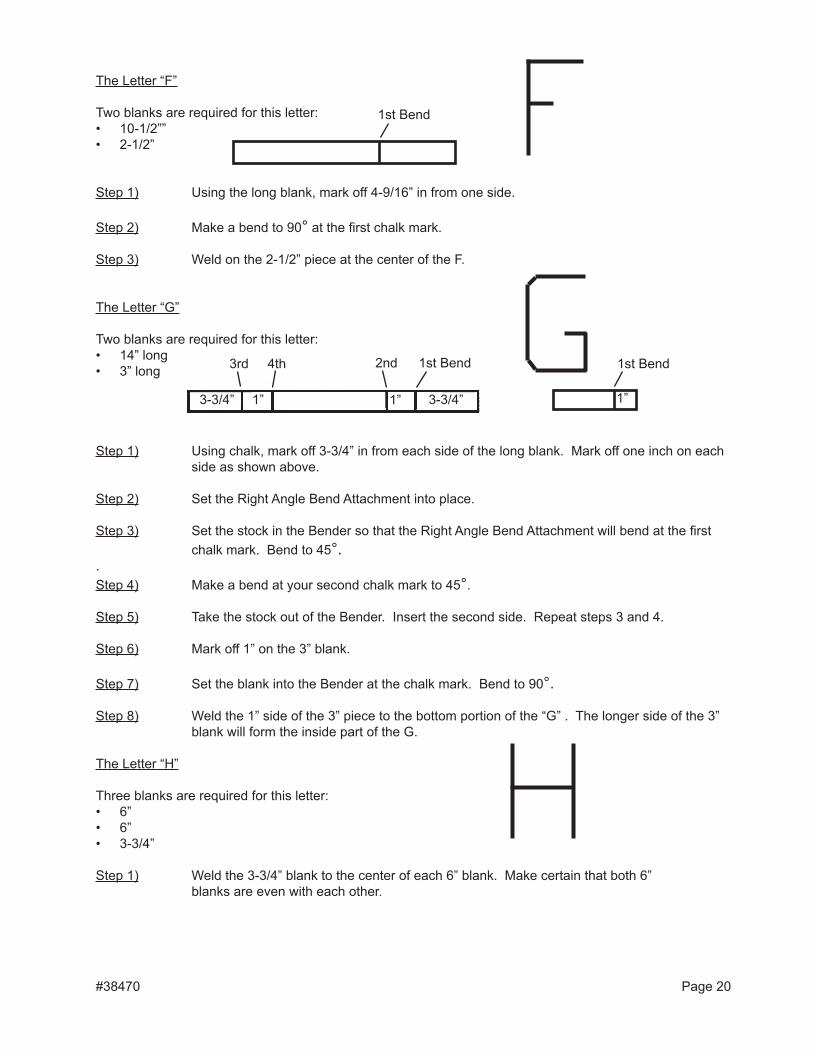
The letter “F”
Two blanks are required for this letter:• 10-1/2””• 2-1/2”
Step 1) Using the long blank, mark off 4-9/16” in from one side.
Step 2) Make a bend to 90° at the first chalk mark.
Step 3) Weld on the 2-1/2” piece at the center of the F.
The letter “G”
Two blanks are required for this letter:• 14” long• 3” long
Step 1) Using chalk, mark off 3-3/4” in from each side of the long blank. Mark off one inch on each side as shown above.
Step 2) Set the Right Angle Bend Attachment into place.
Step 3) Set the stock in the Bender so that the Right Angle Bend Attachment will bend at the first chalk mark. Bend to 45°.
. Step 4) Make a bend at your second chalk mark to 45°.
Step 5) Take the stock out of the Bender. Insert the second side. Repeat steps 3 and 4.
Step 6) Mark off 1” on the 3” blank.
Step 7) Set the blank into the Bender at the chalk mark. Bend to 90°.
Step 8) Weld the 1” side of the 3” piece to the bottom portion of the “G” . The longer side of the 3” blank will form the inside part of the G.
The letter “H”
Three blanks are required for this letter:• 6”• 6”• 3-3/4”
Step 1) Weld the 3-3/4” blank to the center of each 6” blank. Make certain that both 6” blanks are even with each other.
#38470 Page 20
3-3/4” 3-3/4”1”
1st Bend2nd3rd 4th
1”
1st Bend
1”
1st Bend
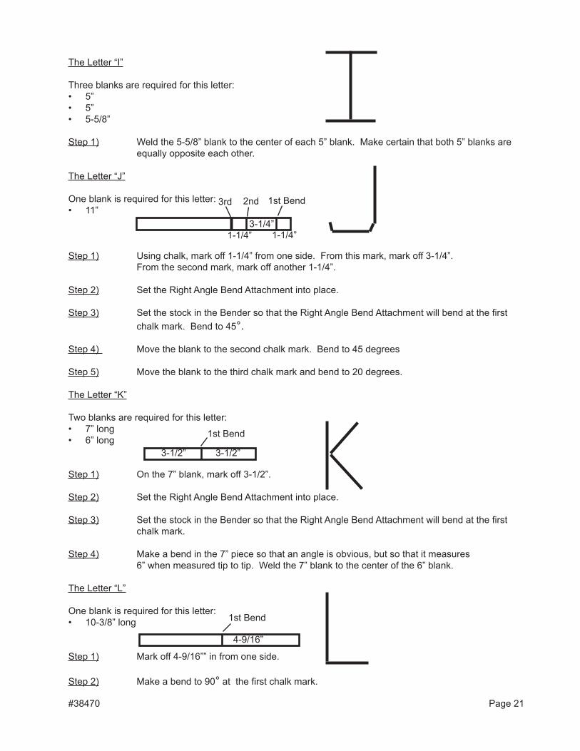
The letter “I”
Three blanks are required for this letter:• 5”• 5”• 5-5/8”
Step 1) Weld the 5-5/8” blank to the center of each 5” blank. Make certain that both 5” blanks are equally opposite each other.
The letter “J”
One blank is required for this letter:• 11”
Step 1) Using chalk, mark off 1-1/4” from one side. From this mark, mark off 3-1/4”. From the second mark, mark off another 1-1/4”. Step 2) Set the Right Angle Bend Attachment into place.
Step 3) Set the stock in the Bender so that the Right Angle Bend Attachment will bend at the first chalk mark. Bend to 45°.
Step 4) Move the blank to the second chalk mark. Bend to 45 degrees
Step 5) Move the blank to the third chalk mark and bend to 20 degrees.
The letter “K”
Two blanks are required for this letter:• 7” long• 6” long
Step 1) On the 7” blank, mark off 3-1/2”.
Step 2) Set the Right Angle Bend Attachment into place.
Step 3) Set the stock in the Bender so that the Right Angle Bend Attachment will bend at the first chalk mark.
Step 4) Make a bend in the 7” piece so that an angle is obvious, but so that it measures 6” when measured tip to tip. Weld the 7” blank to the center of the 6” blank.
The letter “l”
One blank is required for this letter:• 10-3/8” long
Step 1) Mark off 4-9/16”” in from one side.
Step 2) Make a bend to 90° at the first chalk mark.
#38470 Page 21
3-1/4”1-1/4”
1st Bend2nd 3rd
1-1/4”
3-1/2” 3-1/2”
1st Bend
1st Bend
4-9/16”
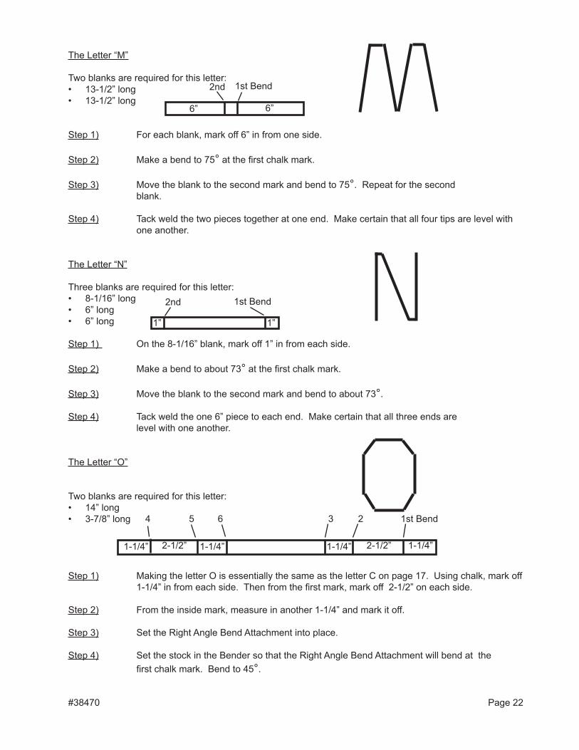
The letter “M”
Two blanks are required for this letter:• 13-1/2” long• 13-1/2” long
Step 1) For each blank, mark off 6” in from one side.
Step 2) Make a bend to 75° at the first chalk mark.
Step 3) Move the blank to the second mark and bend to 75°. Repeat for the second blank.
Step 4) Tack weld the two pieces together at one end. Make certain that all four tips are level with one another.
The letter “N”
Three blanks are required for this letter:• 8-1/16” long• 6” long• 6” long
Step 1) On the 8-1/16” blank, mark off 1” in from each side.
Step 2) Make a bend to about 73° at the first chalk mark.
Step 3) Move the blank to the second mark and bend to about 73°.
Step 4) Tack weld the one 6” piece to each end. Make certain that all three ends are level with one another.
The letter “O”
Two blanks are required for this letter:• 14” long• 3-7/8” long
Step 1) Making the letter O is essentially the same as the letter C on page 17. Using chalk, mark off 1-1/4” in from each side. Then from the first mark, mark off 2-1/2” on each side.
Step 2) From the inside mark, measure in another 1-1/4” and mark it off.
Step 3) Set the Right Angle Bend Attachment into place.
Step 4) Set the stock in the Bender so that the Right Angle Bend Attachment will bend at the first chalk mark. Bend to 45°.
#38470 Page 22
6” 6”
1st Bend2nd
1” 1”
1st Bend2nd
1-1/4” 1-1/4”2-1/2” 2-1/2”1-1/4” 1-1/4”
1st Bend234 5 6
Step 5) Make a bend at your second chalk mark to 45 degrees. Repeat for the third mark.
Step 6) Take the stock out of the Bender. Insert the second side. Repeat steps 3 and 4.
Step 7) Weld the 3-7/8” piece to the open side so that a complete circle is formed.
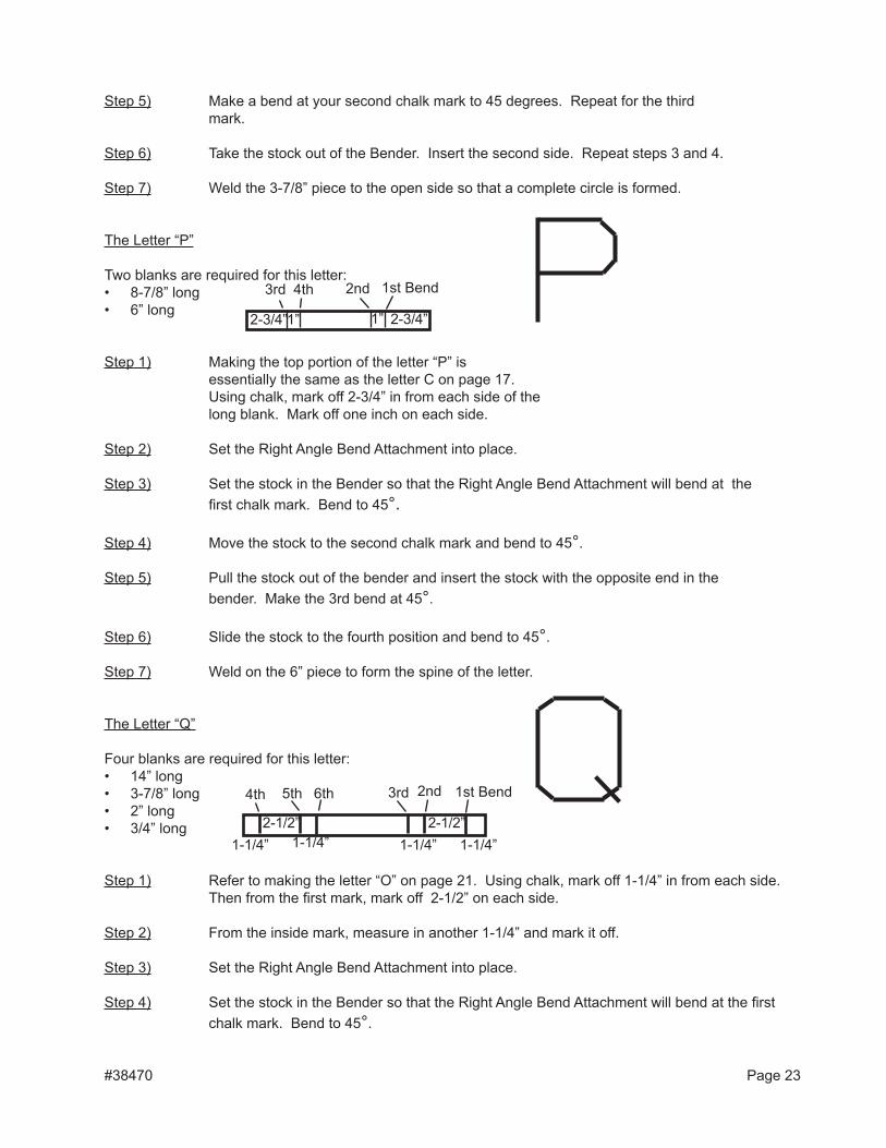
The letter “P”
Two blanks are required for this letter:• 8-7/8” long• 6” long
Step 1) Making the top portion of the letter “P” is essentially the same as the letter C on page 17. Using chalk, mark off 2-3/4” in from each side of the long blank. Mark off one inch on each side.
Step 2) Set the Right Angle Bend Attachment into place.
Step 3) Set the stock in the Bender so that the Right Angle Bend Attachment will bend at the first chalk mark. Bend to 45°.
Step 4) Move the stock to the second chalk mark and bend to 45°.
Step 5) Pull the stock out of the bender and insert the stock with the opposite end in the bender. Make the 3rd bend at 45°.
Step 6) Slide the stock to the fourth position and bend to 45°.
Step 7) Weld on the 6” piece to form the spine of the letter.
The letter “Q”
Four blanks are required for this letter:• 14” long• 3-7/8” long• 2” long• 3/4” long
Step 1) Refer to making the letter “O” on page 21. Using chalk, mark off 1-1/4” in from each side. Then from the first mark, mark off 2-1/2” on each side.
Step 2) From the inside mark, measure in another 1-1/4” and mark it off.
Step 3) Set the Right Angle Bend Attachment into place.
Step 4) Set the stock in the Bender so that the Right Angle Bend Attachment will bend at the first chalk mark. Bend to 45°.
#38470 Page 23
1st Bend2nd3rd 4th
2-3/4” 2-3/4”1” 1”
1st Bend2nd3rd4th
1-1/4”2-1/2”
5th 6th
1-1/4”1-1/4”2-1/2”
1-1/4”
Step 5) Make a bend at your second chalk mark to 45 degrees. Repeat for the third mark.
Step 6) Take the stock out of the Bender. Insert the second side. Repeat steps 4 and 5.
Step 7) Weld the 3-7/8” piece to the open side so that a complete circle is formed.
Step 8) Weld the two short pieces to the right bottom corner of the circle you just completed. The 2” blank should be welded to the inside, with the 3/4” blank on the outside.
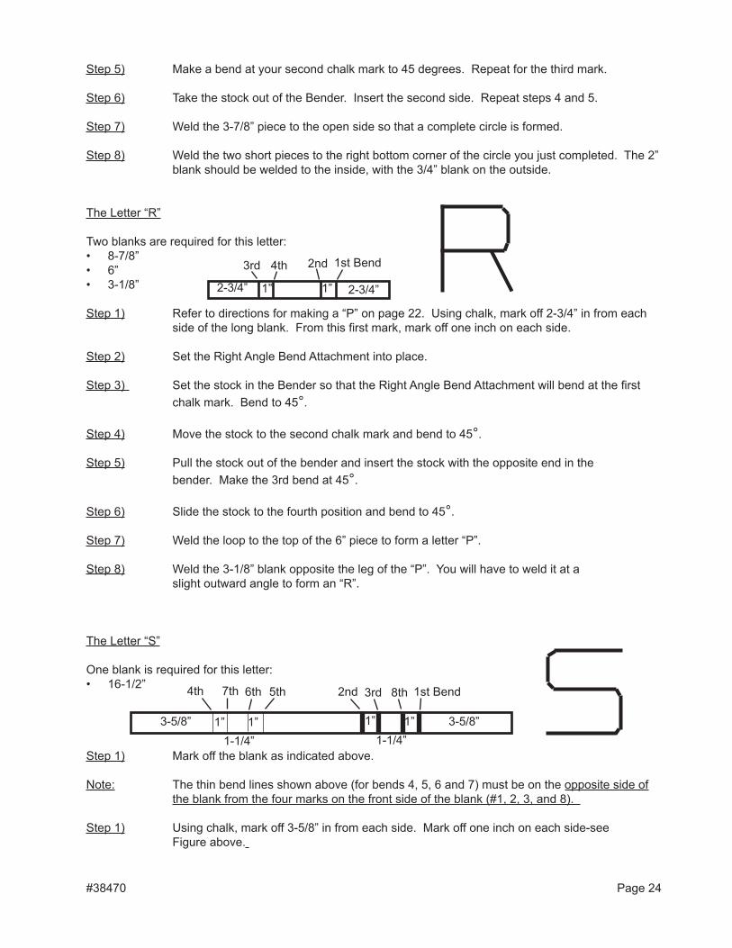
The letter “R”
Two blanks are required for this letter:• 8-7/8”• 6”• 3-1/8”
Step 1) Refer to directions for making a “P” on page 22. Using chalk, mark off 2-3/4” in from each side of the long blank. From this first mark, mark off one inch on each side.
Step 2) Set the Right Angle Bend Attachment into place.
Step 3) Set the stock in the Bender so that the Right Angle Bend Attachment will bend at the first chalk mark. Bend to 45°.
Step 4) Move the stock to the second chalk mark and bend to 45°.
Step 5) Pull the stock out of the bender and insert the stock with the opposite end in the bender. Make the 3rd bend at 45°.
Step 6) Slide the stock to the fourth position and bend to 45°.
Step 7) Weld the loop to the top of the 6” piece to form a letter “P”.
Step 8) Weld the 3-1/8” blank opposite the leg of the “P”. You will have to weld it at a slight outward angle to form an “R”.
The letter “S”
One blank is required for this letter:• 16-1/2”
Step 1) Mark off the blank as indicated above.
Note: The thin bend lines shown above (for bends 4, 5, 6 and 7) must be on the opposite side of the blank from the four marks on the front side of the blank (#1, 2, 3, and 8).
Step 1) Using chalk, mark off 3-5/8” in from each side. Mark off one inch on each side-see Figure above.
#38470 Page 24
1st Bend2nd3rd 4th
2-3/4”1”2-3/4” 1”
1st Bend2nd 3rd4th 5th6th7th 8th
3-5/8”1”1-1/4”
1”3-5/8” 1”1-1/4”
1”
Step 2) Set the Right Angle Bend Attachment into place.
Step 3) Set the stock in the Bender so that the Right Angle Bend Attachment will bend at the first chalk mark. Bend to 45°.
Note: The 2nd and 5th bends are to 41°.
Step 4) Move the blank to the second mark and bend it to 41°.
Step 5) At the third mark bend to 45°.
Step 6) Remove the blank from the Bender. Flip it over and around and insert the other side. At the #4 mark, bend to 45°.
Step 7) At the fifth mark, bend to 41° only.
Step 8) Move the blank to the sixth mark and bend to 45°. Repeat for the seventh mark.
Step 9) Once more remove the blank from the Bender and insert the other side. This may require moving the Right Angle Bend Attachment, inserting the blank and putting back on the Right Angle Bend Attachment. Make certain that the stock is facing the correct way in the Bender. At the #8 mark, bend to 45°.
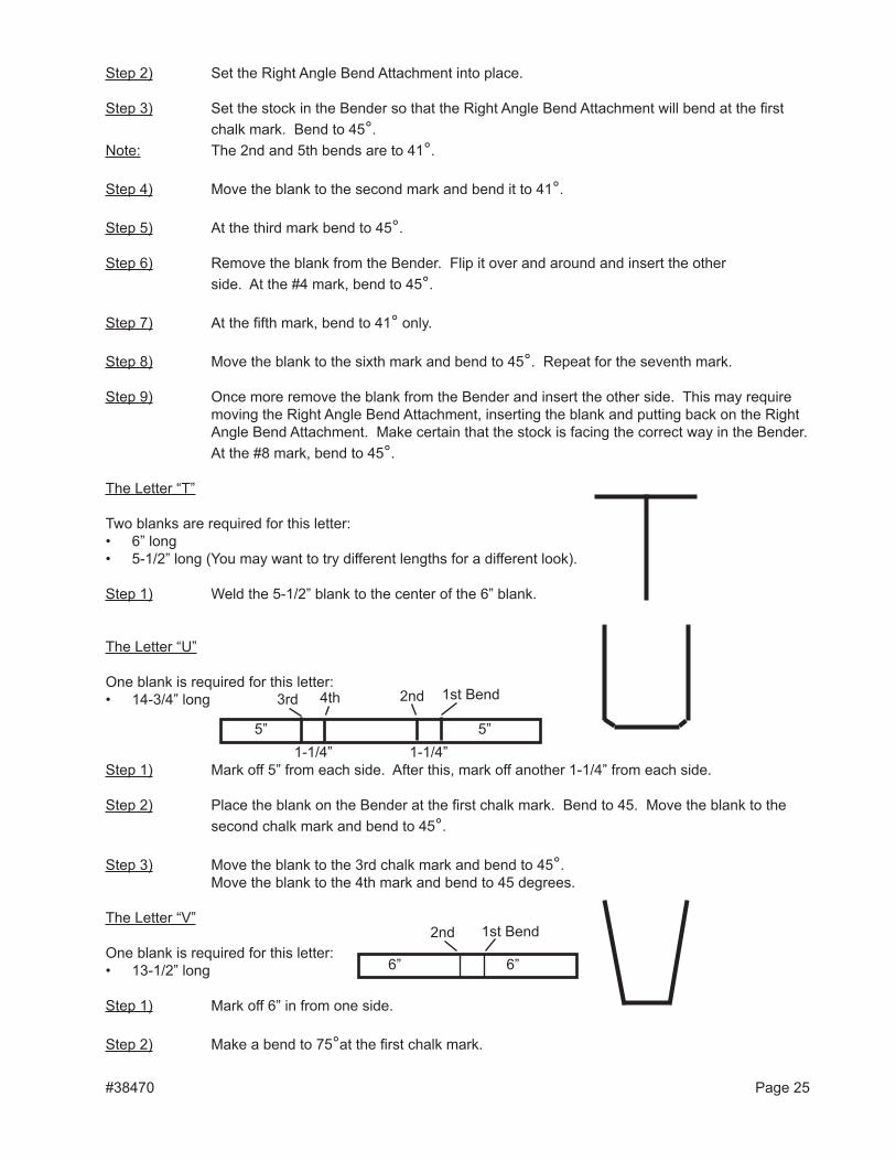
The letter “T”
Two blanks are required for this letter:• 6” long• 5-1/2” long (You may want to try different lengths for a different look).
Step 1) Weld the 5-1/2” blank to the center of the 6” blank.
The letter “U”
One blank is required for this letter:• 14-3/4” long
Step 1) Mark off 5” from each side. After this, mark off another 1-1/4” from each side.
Step 2) Place the blank on the Bender at the first chalk mark. Bend to 45. Move the blank to the second chalk mark and bend to 45°.
Step 3) Move the blank to the 3rd chalk mark and bend to 45°. Move the blank to the 4th mark and bend to 45 degrees.
The letter “V”
One blank is required for this letter:• 13-1/2” long
Step 1) Mark off 6” in from one side.
Step 2) Make a bend to 75°at the first chalk mark.
#38470 Page 25
5” 5”1-1/4” 1-1/4”
1st Bend2nd3rd 4th
6”6”
1st Bend2nd
Step 3) Move the blank to the second mark and bend to 75°.
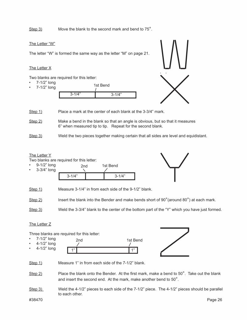
The letter “W”
The letter “W” is formed the same way as the letter “M” on page 21.
The letter X
Two blanks are required for this letter:• 7-1/2” long• 7-1/2” long
Step 1) Place a mark at the center of each blank at the 3-3/4” mark.
Step 2) Make a bend in the blank so that an angle is obvious, but so that it measures 6” when measured tip to tip. Repeat for the second blank.
Step 3) Weld the two pieces together making certain that all sides are level and equidistant.
The letter YTwo blanks are required for this letter:• 9-1/2” long• 3-3/4” long
Step 1) Measure 3-1/4” in from each side of the 9-1/2” blank.
Step 2) Insert the blank into the Bender and make bends short of 90°(around 80°) at each mark.
Step 3) Weld the 3-3/4” blank to the center of the bottom part of the “Y” which you have just formed.
The letter Z
Three blanks are required for this letter:• 7-1/2” long• 4-1/2” long• 4-1/2” long
Step 1) Measure 1” in from each side of the 7-1/2” blank.
Step 2) Place the blank onto the Bender. At the first mark, make a bend to 50°. Take out the blank and insert the second end. At the mark, make another bend to 50°.
Step 3) Weld the 4-1/2” pieces to each side of the 7-1/2” piece. The 4-1/2” pieces should be parallel to each other.
#38470 Page 26
3-1/4” 3-1/4”
1st Bend
3-1/4” 3-1/4”
1st Bend2nd
1” 1”
1st Bend2nd

#38470 Page 27
Please be aware that Harbor Freight Tools offers for sale two attachments that are used with the Compact Bender:
Scroll Bending Attachment (SKU #36621) and Twister Attachment (SKU #36620)
We have included here the Ornamental Wrought Iron Idea and Design Booklet, which gives you some ideas on projects that can be accomplished using the Scroll Bending Attachment and the Twister Attachment.