Embed Size (px)
Citation preview
Quartz Electric installation instuctions page 1
Quartz®
Electric
The Waste Electrical and Electronic Equipment(Producer Responsibility) Regulation 2004
This product is outside the scope of the European Waste Electrical and
Electronic Equipment Directive as interpreted within the UK.
In the UK this product can therefore be disposed of through commercial
non-WEEE waste facilities.
The original manufacturer does not accept any liability under the
WEEE directive.
Quartz Electric installation instuctions page 2
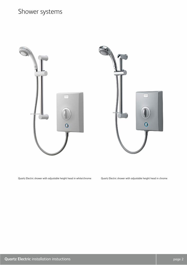
Shower systems
Quartz Electric shower with adjustable height head in chrome Quartz Electric shower with adjustable height head in white/chrome
Quartz Electric installation instuctions page 3
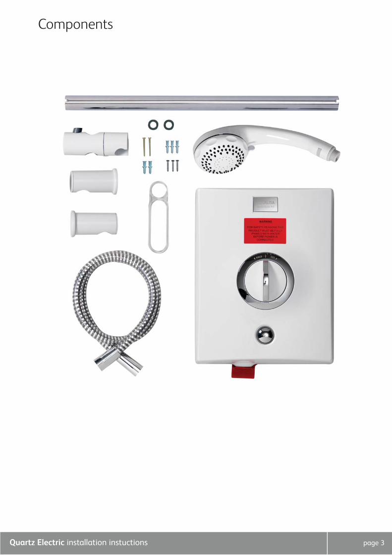
Components
Quartz Electric installation instuctions page 4
Important information
IntroductionQuartz Electric is a surface mounted instantaneous electric shower unit which is available in a choice of performance ratings –
8.5kW and 9.5kW available in White/chrome or Satin chrome or 10.5kW available in Satin chrome.
Quartz Electric’s patented Over Temperature Protection (OTP) device ensures safer comfortable showering as well as providing
endless economical showering as it imposes no demand on stored hot water.
Quartz Electric is supplied with a 2 year guarantee. The guarantee can be extended by a further 2 years by completing the
optional guarantee extension agreement document supplied with the product and posting it to Aqualisa Products Ltd.
If you have any questions at any stage during installation please contact the Aqualisa customer helpline on 01959 560010 for advice.
Safety information This product must be installed by a competent person in accordance with all relevant current Water Supply Regulations.
ALL SHOWERS REQUIRING AN ELECTRICAL CONNECTION MUST BE INSTALLED BY A QUALIFIED PERSON FOLLOWING THE
LATEST REVISION OF BS 7671 (WIRING REGULATIONS) AND CERTIFIED TO CURRENT BUILDING REGULATIONS.
WITH REFERENCE TO BUILDING REGULATION PART P, ANY NEW INSTALLATION OR REPLACEMENT PRODUCT
INSTALLATION WHICH IS NOT IDENTICAL TO THE PRODUCT BEING REPLACED, THE CABLE SIZES, CIRCUIT PROTECTIVE
DEVICES, EARTH BONDING AND ALL OTHER REQUIREMENTS OF THE BUILDING REGULATION MUST BE ASSESSED BY A
(REGISTERED) QUALIFIED ELECTRICIAN AND INSTALLED IN CONSIDERATION TO THE SITE CONDITIONS (see table below).
Notes:-
1. Cable selection is dependant on de-rating factors detailed in the electrical rating section overleaf.
2. In certain installations the combination of low voltage and extended cable lengths may result in loss of power and a
consequential reduction in flow rates.
3. Above cable sizes are the minimum acceptable sizes. Sizes greater than these shown above may be used and should be used
if cable runs are greater than indicated (above cable runs are based on a maximum 9.6V drop).
4. Rewirable fuses are not recommended and are not covered by this table.
5. Installation should be carried out by a qualified person. Please refer to BS7671 (Wiring Regulations) if in doubt.
6. A 16mm2 cable may be required for long cable runs.
Cables which are chased into the wall must be protected by the use of conduit or sheathing. Surface mounted cables must also
be protected by a suitable approved conduit.
Before removing the shower heater cover, ensure the heater is isolated from the electric mains.
This appliance is not intended for use by persons (including children) with reduced physical, sensory or mental capabilities or
lack of experience and knowledge unless they have been given initial supervision or instruction concerning the use of the
appliance by a person responsible for their safety.
Children should be supervised to ensure that they do not play with the appliance.
Quartz Electric is suitable for household use only.
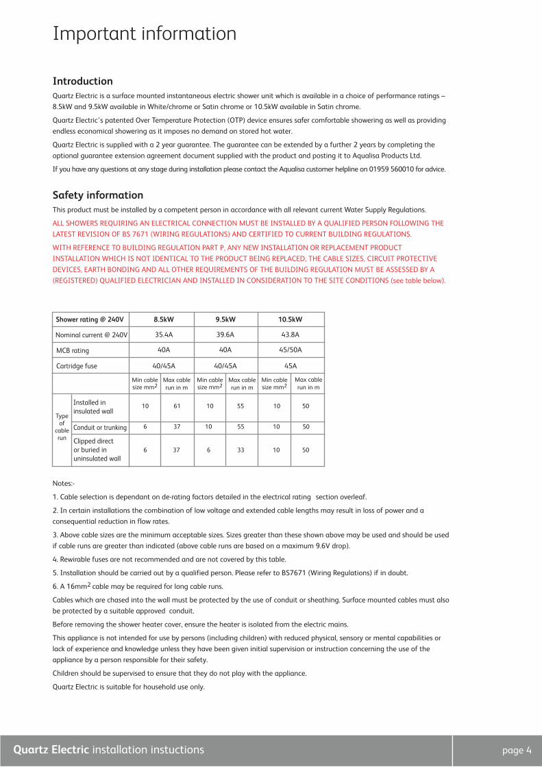
Shower rating @ 240V 8.5kW
35.4A 39.6A 43.8A
40A 40A 45/50A
40/45A
Min cablesize mm2
10
6
6 37 6 33 10 50
37 10 55 10 50
61 10 55 10 50
Max cablerun in m
Min cablesize mm2
Max cablerun in m
Min cablesize mm2
Max cablerun in m
40/45A 45A
9.5kW 10.5kW
Nominal current @ 240V
MCB rating
Conduit or trunking
Cartridge fuse
Installed in insulated wall
Clipped direct or buried in uninsulated wall
Typeof
cablerun
Quartz page 5
Important information
FlushingSome modern fluxes can be extremely corrosive and, if left in contact, will attack the working parts of this unit. All
soldering must be completed and the pipe work thoroughly flushed out in accordance with current Water Supply Regulations
prior to connection of the product.
ConnectionsQuartz Electric is suitable for use with 15mm British Standard pipe and should be connected using a 15mm compression
fitting (not supplied). Quartz Electric is suitable for top, bottom or rear entry pipe work and top bottom or rear entry cable.
Supply lines should be flushed clear of any debris prior to installation of the unit.
Isolating valvesA suitable full bore isolation valve must be fitted to the incoming supply in accordance with the current Water Supply
Regulations and our terms of warranty.
SitingThe Quartz Electric unit must be mounted on a flat, vertical finished wall with the hose outlet pointing downwards. Any
distortion of the back plate may result in the unit not working. Spacers are provided fitted to the service tunnel to enable the
unit to be fitted to an uneven wall surface.
DO NOT tile up to or use sealants around the Quartz Electric unit. The shower is spaced off the wall by integral pillars to allow
air circulation around the unit.
The casing must not be sited where it is subjected to continuous spray from the shower head.
The Quartz Electric should not be sited in any situation where it is likely to freeze.
! WARNING. DO NOT SWITCH THE SHOWER ON IF THERE IS A POSSIBILITY THAT THE SHOWER COULD BE FROZEN. If you
have switched the shower on, SWITCH OFF IMMEDIATELY. Please refer to the trouble shooting guide overleaf.
PressuresCheck that the dynamic (running) water pressure to the Quartz Electric is adequate. Quartz Electric requires:
Max: 1.0MPa (10 bar)
Min: 0.09MPa (0.9 bar) at a flow rate of 8Lpm
The Quartz Electric shower is designed to control static pressure up to 1.0MPa (10 bar). Where pressures are likely to exceed
1.0MPa (10 bar), a pressure reducing valve must be fitted into the incoming mains supply. A setting of 0.3MPa (3 bar) is
recommended. It should be noted that daytime pressures approaching 8 bar can rise above the stated maximum overnight. A
suitable pressure reducing valve is available from Aqualisa.
The use of other services connected to the water supply to the shower unit may cause the water pressure to drop below the
minimum required. This should therefore be taken into consideration.
Pressure relief device (PRD)To meet European standards, the shower unit features an integral pressure relief device (PRD). The PRD provides a degree of
shower unit protection should an excessive build up of pressure occur within the shower.
DO NOT operate the shower with a damaged or kinked hose or blocked shower head, as this can cause the PRD to operate.
Failure to follow this instruction will invalidate the guarantee.
The shower will only function correctly with the hose and handset provided (see shower head installation instructions overleaf).
Failure to do so may result in the operation of the PRD and will invalidate the guarantee.
Please fully commission the shower prior to use following the shower commissioning procedure detailed overleaf. Failure to do
so could cause the PRD to operate and will invalidate the guarantee.
The shower unit must be sited over a bath or shower tray as in the event of the PRD operating, water will drain from the
bottom of the shower unit.
Quartz Electric installation instuctions page 6
Step-by-step instructions
In addition to the guide below it is essential that the written instructions
overleaf are read and understood and that you have all the necessary
components (shown overleaf) before commencing installation. Failure to
install the product in accordance with these instructions may adversely affect
the warranty terms and conditions. Do not undertake any part of this
installation unless you are qualified to do so. Prior to starting, ensure that
you are familiar with the necessary plumbing and electrical regulations and
legislation required to install the product correctly and safely.
The Quartz Electric is supplied with universal fittings intended to secure the
unit to a suitable wall.
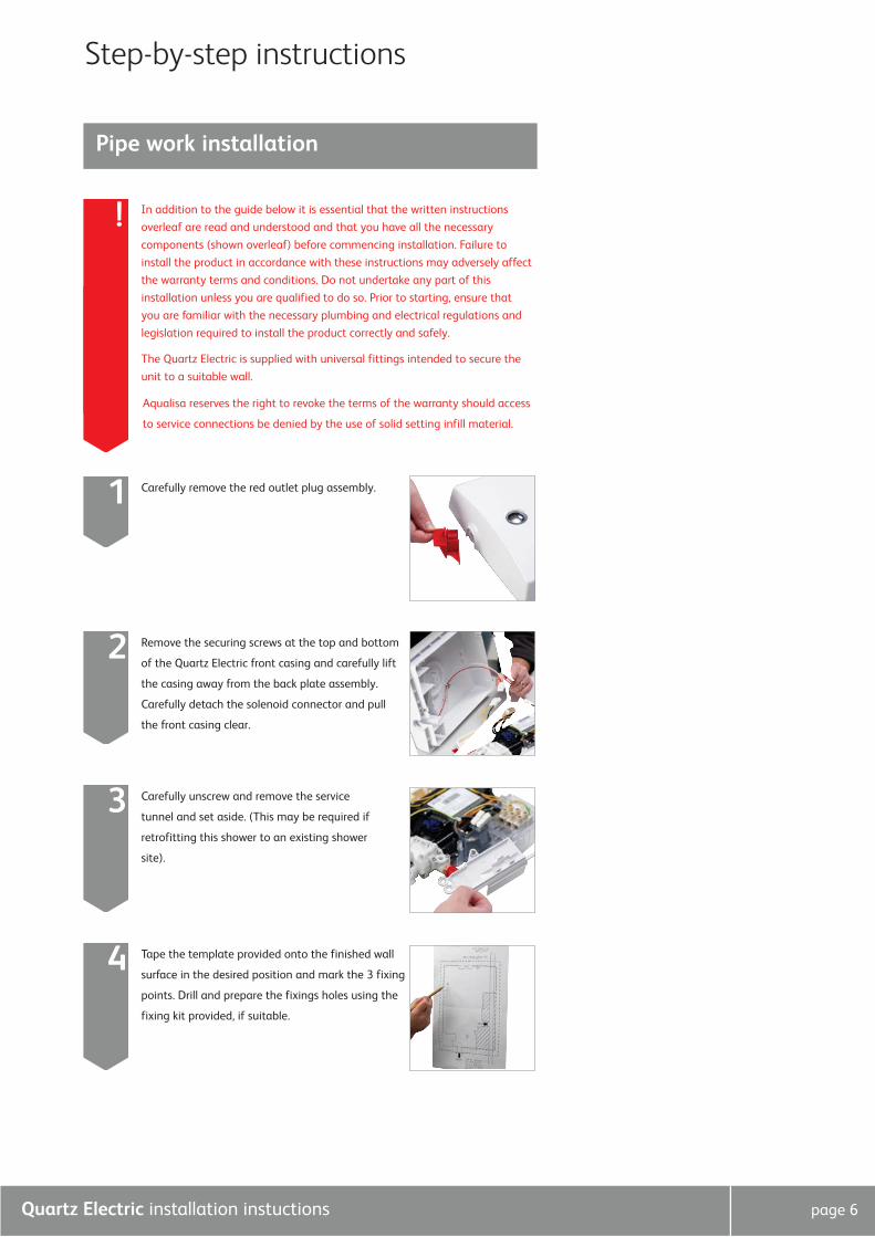
Carefully remove the red outlet plug assembly. 1
Pipe work installation
Remove the securing screws at the top and bottom
of the Quartz Electric front casing and carefully lift
the casing away from the back plate assembly.
Carefully detach the solenoid connector and pull
the front casing clear.
2
!
Carefully unscrew and remove the service
tunnel and set aside. (This may be required if
retrofitting this shower to an existing shower
site).
3
Tape the template provided onto the finished wall
surface in the desired position and mark the 3 fixing
points. Drill and prepare the fixings holes using the
fixing kit provided, if suitable.
4
Aqualisa reserves the right to revoke the terms of the warranty should access
to service connections be denied by the use of solid setting infill material.
Quartz Electric installation instuctions page 7
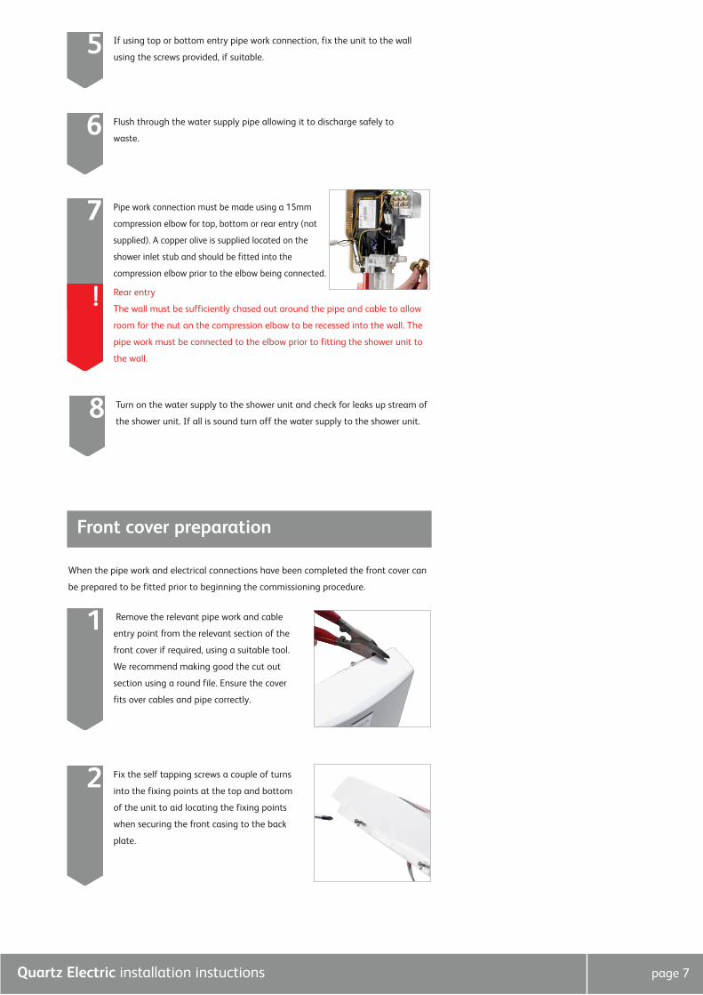
Pipe work connection must be made using a 15mm
compression elbow for top, bottom or rear entry (not
supplied). A copper olive is supplied located on the
shower inlet stub and should be fitted into the
compression elbow prior to the elbow being connected.
7
Rear entry
The wall must be sufficiently chased out around the pipe and cable to allow
room for the nut on the compression elbow to be recessed into the wall. The
pipe work must be connected to the elbow prior to fitting the shower unit to
the wall.
!
If using top or bottom entry pipe work connection, fix the unit to the wall
using the screws provided, if suitable.5
Flush through the water supply pipe allowing it to discharge safely to
waste.6
Turn on the water supply to the shower unit and check for leaks up stream of
the shower unit. If all is sound turn off the water supply to the shower unit.8
Front cover preparation
When the pipe work and electrical connections have been completed the front cover can
be prepared to be fitted prior to beginning the commissioning procedure.
Remove the relevant pipe work and cable
entry point from the relevant section of the
front cover if required, using a suitable tool.
We recommend making good the cut out
section using a round file. Ensure the cover
fits over cables and pipe correctly.
1
Fix the self tapping screws a couple of turns
into the fixing points at the top and bottom
of the unit to aid locating the fixing points
when securing the front casing to the back
plate.
2
Quartz Electric installation instuctions page 8
BEFORE ANY ELECTRICAL CONNECTION IS ATTEMPTED, THE ELECTRICITY
SUPPLY MUST BE TURNED OFF AT THE MAIN SWITCH. FAILURE TO DO SO
COULD RESULT IN ELECTROCUTION.
The electrical installation should be carried out by a qualified person in
accordance with IEE (Institution of Electrical Engineers) wiring regulations
(BS 7671).
THIS APPLIANCE MUST BE EARTHED.
IN THE INTERESTS OF ELECTRICAL SAFETY, A 30mA RESIDUAL CURRENT
DEVICE (RCD) SHOULD BE INSTALLED IN ALL UK 230-240V ELECTRIC
SHOWERS AND PUMPED CIRCUITS. THIS MAY BE PART OF A CONSUMER
UNIT OR A SEPERATE UNIT.
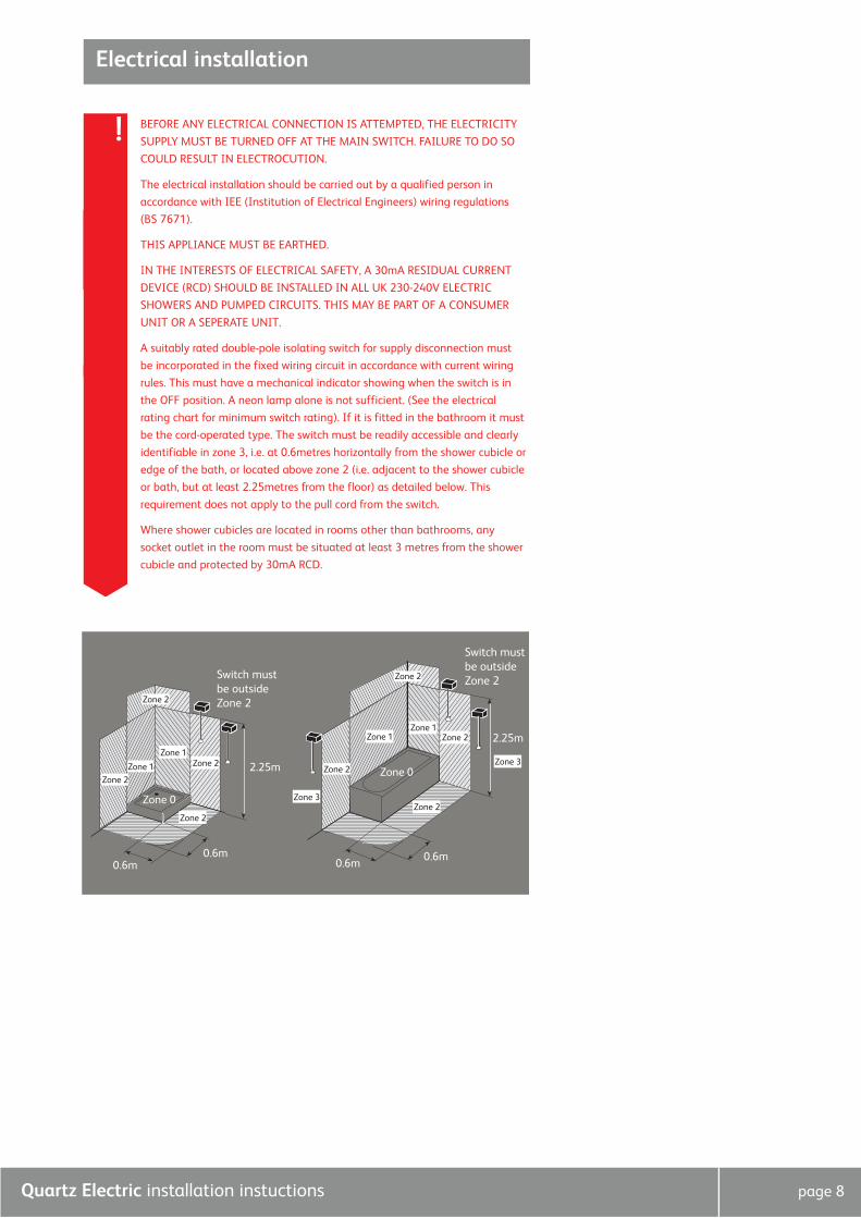
A suitably rated double-pole isolating switch for supply disconnection must
be incorporated in the fixed wiring circuit in accordance with current wiring
rules. This must have a mechanical indicator showing when the switch is in
the OFF position. A neon lamp alone is not sufficient. (See the electrical
rating chart for minimum switch rating). If it is fitted in the bathroom it must
be the cord-operated type. The switch must be readily accessible and clearly
identifiable in zone 3, i.e. at 0.6metres horizontally from the shower cubicle or
edge of the bath, or located above zone 2 (i.e. adjacent to the shower cubicle
or bath, but at least 2.25metres from the floor) as detailed below. This
requirement does not apply to the pull cord from the switch.
Where shower cubicles are located in rooms other than bathrooms, any
socket outlet in the room must be situated at least 3 metres from the shower
cubicle and protected by 30mA RCD.
!
Electrical installation
Zone 0
Zone 0
Zone 2
Zone 2
Zone 2
Zone 2
Zone 1Zone 1
Zone 3
Zone 3
Zone 2
Zone 1
Zone 1 Zone 2
Zone 2
Zone 2
Switch mustbe outsideZone 2
2.25m
2.25m
0.6m0.6m0.6m
0.6m
Switch mustbe outsideZone 2
Quartz Electric installation instuctions page 9
Mains voltage connection
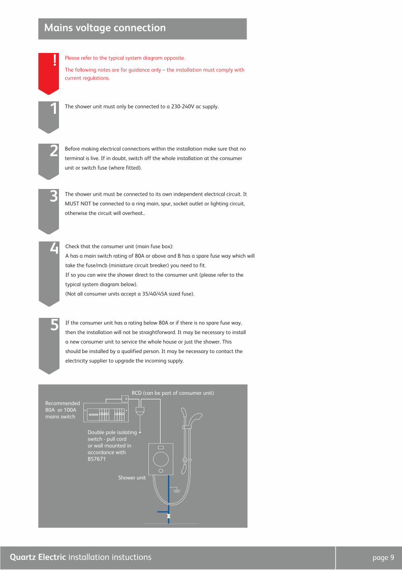
Please refer to the typical system diagram opposite.
The following notes are for guidance only – the installation must comply with
current regulations.
!
RCD (can be part of consumer unit)
Recommended80A or 100Amains switch
Double pole isolatingswitch - pull cordor wall mounted inaccordance withBS7671
Shower unit
The shower unit must only be connected to a 230-240V ac supply.1
Before making electrical connections within the installation make sure that no
terminal is live. If in doubt, switch off the whole installation at the consumer
unit or switch fuse (where fitted).
2
The shower unit must be connected to its own independent electrical circuit. It
MUST NOT be connected to a ring main, spur, socket outlet or lighting circuit,
otherwise the circuit will overheat..
3
Check that the consumer unit (main fuse box):
A has a main switch rating of 80A or above and B has a spare fuse way which will
take the fuse/mcb (miniature circuit breaker) you need to fit.
If so you can wire the shower direct to the consumer unit (please refer to the
typical system diagram below).
(Not all consumer units accept a 35/40/45A sized fuse).
4
If the consumer unit has a rating below 80A or if there is no spare fuse way,
then the installation will not be straightforward. It may be necessary to install
a new consumer unit to service the whole house or just the shower. This
should be installed by a qualified person. It may be necessary to contact the
electricity supplier to upgrade the incoming supply.
5
Quartz Electric installation instuctions page 10
Wiring installation
Electrical rating
Replace the service tunnel and secure using the fixing screw provided. 2
Refer to the electrical rating diagram (shown overleaf) to determine the nominal current
of the shower. The current rating of the supply cable must be at least that of the shower
itself. Use the rating chart to choose a fuse or mcb with a rating of less than that of
your chose cable.
! WE STRONGLY RECOMMEND NOT USING REWIRABLE FUSES.
If the cable is to be:
A bunched with others
B in an ambient temperature above 40ºC
C in an insulating wall or within thermal insulation, e.g. loft insulation.
D in any other unusual position
The current rating will be reduced.
If in doubt about any aspect of electrical installation, consult a qualified electrical
engineer or the electricity supplier.
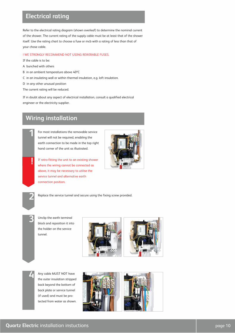
For most installations the removable service
tunnel will not be required, enabling the
earth connection to be made in the top right
hand corner of the unit as illustrated.
1
If retro-fitting the unit to an existing shower
where the wiring cannot be connected as
above, it may be necessary to utilise the
service tunnel and alternative earth
connection position.
!
Unclip the earth terminal
block and reposition it into
the holder on the service
tunnel.
3
!
Any cable MUST NOT have
the outer insulation stripped
back beyond the bottom of
back plate or service tunnel
(if used) and must be pro-
tected from water as shown.
4
Quartz Electric installation instuctions page 11
The installation must be earth bonded in accordance with current regulations
Where earth bonding of the premises is not evident, it may be necessary to
run bonding cable back to the earth terminal at the consumer unit.
!
Shower head installation
Earth bonding
The shower head should be sited close to the shower unit, not necessarily on the same
wall, but not so that the unit is subjected to continuous spray. The shower head should
be sited so that it is no more than 610mm (2ft) above the bottom of the unit or no lower
than 305mm (1ft) below the unit, when in its normal position in the shower head holder.
! THE SHOWER OUTLET, HOSE AND HANDSET ACT AS A VENT. THEY MUST NOT BE
BLOCKED, OBSTRUCTED OR HAVE CONNECTED TO THEM ANY FITTING NOT
APPROVED BY US. THE USE OF UNAPPROVED ACCESSORIES MAY INVALIDATE THE
GUARANTEE AND MAY AFFECT THE PERFORMANCE AND SAFETY OF THE UNIT.
Prepare two fixing points 465 – 470mm vertically apart using the fixings
provided, if suitable. 1
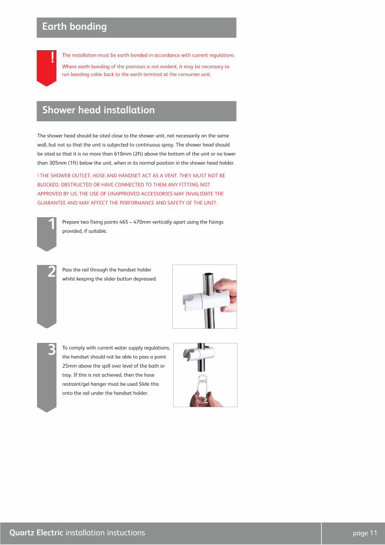
Pass the rail through the handset holder
whilst keeping the slider button depressed. 2
To comply with current water supply regulations,
the handset should not be able to pass a point
25mm above the spill over level of the bath or
tray. If this is not achieved, then the hose
restraint/gel hanger must be used Slide this
onto the rail under the handset holder.
3
Quartz Electric installation instuctions page 12
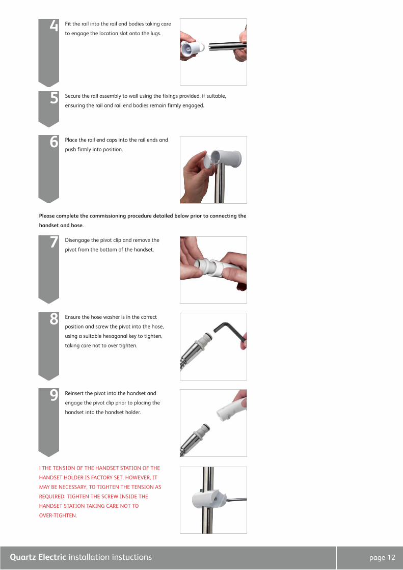
Fit the rail into the rail end bodies taking care
to engage the location slot onto the lugs. 4
Ensure the hose washer is in the correct
position and screw the pivot into the hose,
using a suitable hexagonal key to tighten,
taking care not to over tighten.
8
Reinsert the pivot into the handset and
engage the pivot clip prior to placing the
handset into the handset holder.
9
Secure the rail assembly to wall using the fixings provided, if suitable,
ensuring the rail and rail end bodies remain firmly engaged. 5
Place the rail end caps into the rail ends and
push firmly into position. 6
Please complete the commissioning procedure detailed below prior to connecting the
handset and hose.
Disengage the pivot clip and remove the
pivot from the bottom of the handset. 7
! THE TENSION OF THE HANDSET STATION OF THE
HANDSET HOLDER IS FACTORY SET. HOWEVER, IT
MAY BE NECESSARY, TO TIGHTEN THE TENSION AS
REQUIRED. TIGHTEN THE SCREW INSIDE THE
HANDSET STATION TAKING CARE NOT TO
OVER-TIGHTEN.
Quartz Electric installation instuctions page 13
This shower must be fully commissioned following the procedure detailed
below before use. Failure to do so could damage the shower and invalidate
the guarantee.
Front cover installation and shower commissioning
!
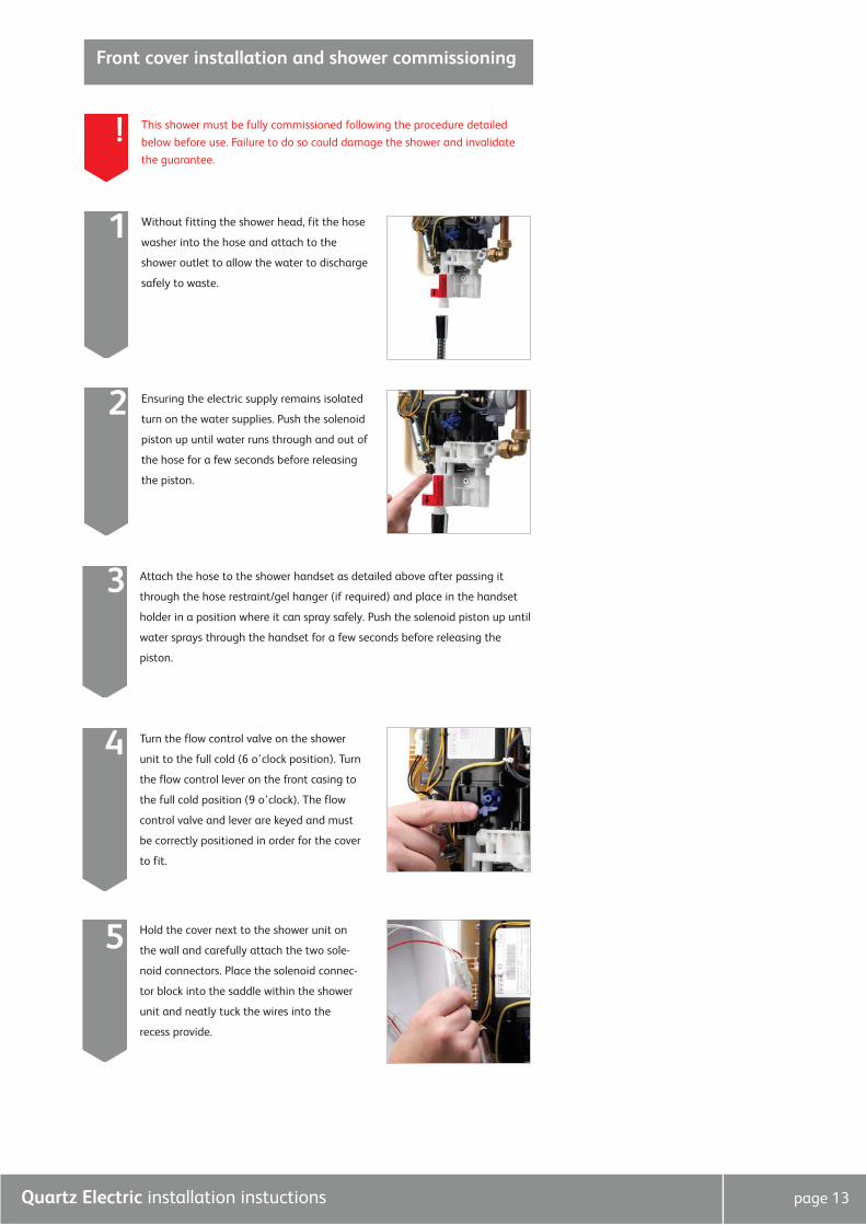
Attach the hose to the shower handset as detailed above after passing it
through the hose restraint/gel hanger (if required) and place in the handset
holder in a position where it can spray safely. Push the solenoid piston up until
water sprays through the handset for a few seconds before releasing the
piston.
3
Turn the flow control valve on the shower
unit to the full cold (6 o’clock position). Turn
the flow control lever on the front casing to
the full cold position (9 o’clock). The flow
control valve and lever are keyed and must
be correctly positioned in order for the cover
to fit.
4
Without fitting the shower head, fit the hose
washer into the hose and attach to the
shower outlet to allow the water to discharge
safely to waste.
1
Ensuring the electric supply remains isolated
turn on the water supplies. Push the solenoid
piston up until water runs through and out of
the hose for a few seconds before releasing
the piston.
2
Hold the cover next to the shower unit on
the wall and carefully attach the two sole-
noid connectors. Place the solenoid connec-
tor block into the saddle within the shower
unit and neatly tuck the wires into the
recess provide.
5
Quartz Electric installation instuctions page 14
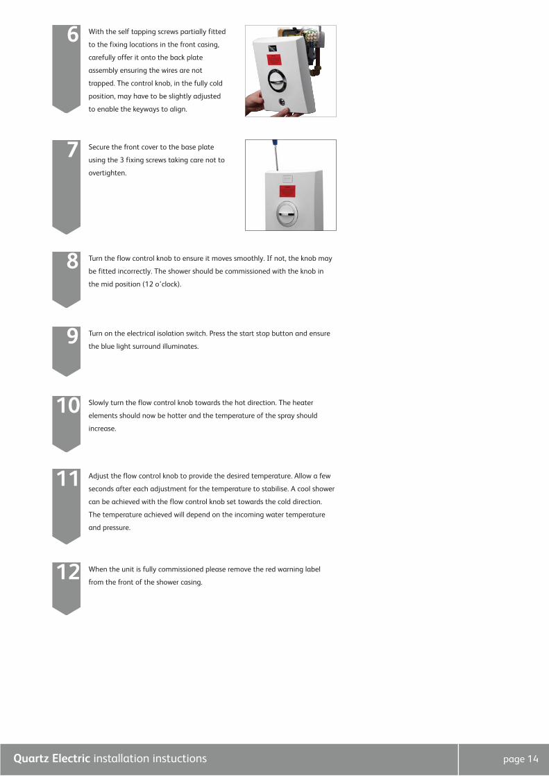
With the self tapping screws partially fitted
to the fixing locations in the front casing,
carefully offer it onto the back plate
assembly ensuring the wires are not
trapped. The control knob, in the fully cold
position, may have to be slightly adjusted
to enable the keyways to align.
6
Secure the front cover to the base plate
using the 3 fixing screws taking care not to
overtighten.
7
Turn the flow control knob to ensure it moves smoothly. If not, the knob may
be fitted incorrectly. The shower should be commissioned with the knob in
the mid position (12 o’clock).
8
Slowly turn the flow control knob towards the hot direction. The heater
elements should now be hotter and the temperature of the spray should
increase.
10
When the unit is fully commissioned please remove the red warning label
from the front of the shower casing.12
Adjust the flow control knob to provide the desired temperature. Allow a few
seconds after each adjustment for the temperature to stabilise. A cool shower
can be achieved with the flow control knob set towards the cold direction.
The temperature achieved will depend on the incoming water temperature
and pressure.
11
Turn on the electrical isolation switch. Press the start stop button and ensure
the blue light surround illuminates.9
Quartz Electric installation instuctions page 15
Inspection & maintenance In the interests of safety, we recommend the Quartz Electric and its electrical installation are checked by a qualified electrician
at least every 2 years.
Cleaning the filter should only be completed by a qualified person. Please refer to the instructions opposite of how to clean the
filter.
After installation Familiarise the end user with the Quartz Electric operation and hand them this guide.
Complete and post the Quartz Electric guarantee card and optional guarantee extension agreement document.
Cleaning & maintenanceYour Quartz Electric unit should be cleaned using only a soft cloth and washing up liquid.
DO NOT USE ABRASIVE CLEANERS.
To reduce the requirement for chemical descaling in hard water areas, the shower head incorporates rub clean teats. Any scale
build up that may occur in any of the holes can be broken down by gently rubbing the flexible tips of the jets during use. This
procedure should be completed regularly, as often as once a week in some hard water areas as scale build up can affect the
spray pattern and cause the shower to perform poorly.
Should chemical descaling of the head become necessary, remove the shower head and fully immerse in a mild proprietary
descalent.
! IT IS IMPERATIVE THAT DESCALING IS CARRIED OUT STRICTLY IN ACCORDANCE WITH THE MANUFACTURERS INSTRUC-
TIONS. SUBSTANCES THAT ARE NOT SUITABLE FOR PLASTICS AND ELECTROPLATED SURFACES MUST NOT BE USED.
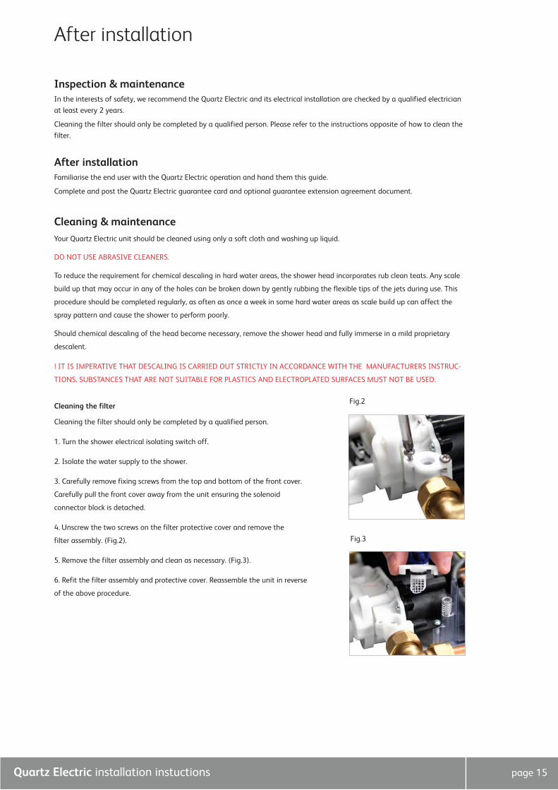
Cleaning the filter
Cleaning the filter should only be completed by a qualified person.
1. Turn the shower electrical isolating switch off.
2. Isolate the water supply to the shower.
3. Carefully remove fixing screws from the top and bottom of the front cover.
Carefully pull the front cover away from the unit ensuring the solenoid
connector block is detached.
4. Unscrew the two screws on the filter protective cover and remove the
filter assembly. (Fig.2).
5. Remove the filter assembly and clean as necessary. (Fig.3).
6. Refit the filter assembly and protective cover. Reassemble the unit in reverse
of the above procedure.
Fig.2
Fig.3
After installation
Quartz Electric installation instuctions page 16
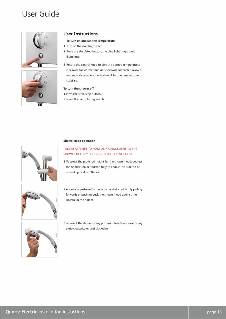
User InstructionsTo turn on and set the temperature
1 Turn on the isolating switch.
2 Press the start/stop button, the blue light ring should
illuminate.
3 Rotate the control knob to give the desired temperature;
clockwise for warmer and anticlockwise for cooler. Allow a
few seconds after each adjustment for the temperature to
stabilise.
To turn the shower off
1 Press the start/stop button.
2 Turn off your isolating switch.
Shower head operation
! NEVER ATTEMPT TO MAKE ANY ADJUSTMENT TO THE
SHOWER HEAD BY PULLING ON THE SHOWER HOSE.
1 To select the preferred height for the shower head, depress
the handset holder button fully to enable the slider to be
moved up or down the rail.
2 Angular adjustment is made by carefully but firmly pulling
forwards or pushing back the shower head against the
knuckle in the holder.
3 To select the desired spray pattern rotate the shower spray
plate clockwise or anti-clockwise.
User Guide
Aqualisa Products Limited
The Flyer’s Way
Westerham Kent TN16 1DE
Sales enquiries: 01959 560010
Republic of Ireland 01-864-3363
Customer helpline: 01959 560010
Republic of Ireland 01-844-3212
Brochure Hotline: 0800 652 3669
Website: www.aqualisa.co.uk
Email: [email protected]
Please note that calls may be recorded for training and quality purposes
The company reserves the right to alter, change or modify the product specifications without prior warning
® Registered Trademark Aqualisa Products Limited

Check out our full range of Showers Electric Showers
Digital Showers
Mixer Showers
Power Showers
Smart Showers
Shower Towers
From Top Shower Brands Mira Showers
Aqualisa Showers
Triton Showers
Gainsborough Showers
Shower Pumps can upgrade your showering experience even more Stuart Turner Shower Pumps
Salamander Shower Pumps
Grundfos Shower Pumps