Embed Size (px)
Citation preview

International Journal of Engineering Research ISSN:2319-6890(online),2347-5013(print) Volume No.5 Issue: Special 3 pp: 545-548 27-28 Feb. 2016
NCASE@2016 doi : 10.17950/ijer/v5i3/007 Page 545
Approaches to Beam, Slab & Staircase Designing Using Limit State Design Method for Achieving Optimal Stability Conditions
Utpal Kumar Nandy, Shravani Nandy, Antara Nandy
C.M.D, B.U. Builders & Consultants Pvt. Ltd, ISO 9001:2000 (QMS); Add: ‘NILANJAN’, D1/114, Sector-IV, Vinay Nagar, Gwalior (M.P.)-474012, INDIA
Email: [email protected] Abstract- Building design and construction of multi-story buildings involves a network of highly complex and meticulous processes. It is imperative to carry out these processes with great care and concern for achieving desired levels of stability conditions. Using the ultimate load values, the designing of essential structural members have been outlined in the paper. The structural elements used as a basis for carrying out the design calculations include beams, slabs and staircase. The paper presents the various steps of calculations required for computing the correct values. The necessary parameters and design criteria have been shown that will facilitate the design as well as evaluation of the structures. A base plan has been used as an illustrative example to conduct the calculations on. Keywords: Limit State Design, Reinforced beam, Reinforced Slab, Staircase, Ultimate Load 1. Introduction 1.1 Beams Beams are horizontal structural members constructed below the slab and are connected to the columns. These members span along the length of a given edge. Beams are responsible for carrying the load of the structural elements built above and then transmitting the load to the columns connected to it. Beams can be constructed using wood, steel, concrete, reinforced cement concrete and even plastic. The construction of beams can be carried out in two ways i.e. cast-in situ and laying of prefabricated beams. Beams are constructed at an average distance of 3m centre to centre. By suitably fixing the length and depth of the beam, the requirement of the number of beams can be reduced and hence the overall construction cost can be controlled. 1.2 Design of Beams When a beam is subjected to a bending moment, compressive and tensile stresses are set up in its fibres. The intensity of stress in any fibre is proportional to its distance from the neutral axis. As long as the stresses in the concrete are within their elastic limits, the stresses in steel and concrete are in their modular ratio and the beam behaves homogeneously. The tensile stress in concrete surrounding
the steel is equal to , where is the tensile stress at any stage of loading (Plain and Reinforced Concrete-Code of Practice, 2000).
The equations used for the design of reinforced cement concrete beams are given below (Plain and Reinforced Concrete-Code of Practice, 2000).
;
Further,
Therefore, the final load,
Load on concrete,
Load on steel,
The factor is called the equivalent area of the section.
When the depth and the breadth of a beam needs to follow certain restrictions due to various reasons such as enhancing the appearance, it becomes essential to provide steel on the compression side of the beam as well. If the permissible dimension given by the expression, , are greater than the restricted dimension then the moment of resistance with respect to compression with smaller than the applied bending moment. Steel provided on the compressive side increases the capacity of the beam to resist compressive forces without increasing its size. Beams of such kind are known as doubly reinforced beams (Krishna & Jain, 1977). Let Asc and At be the areas of steel in the compression and tension zones of the section respectively. Since plane sections of the beam remain plane after bending, we have:-
Where, N, a and d represent the neutral axis coefficient, width and depth of the beam section while and are the compressive stresses in the concrete of beam. The value of the neutral axis coefficient can be calculated using the following equation (Krishna & Jain, 1977).

International Journal of Engineering Research ISSN:2319-6890(online),2347-5013(print) Volume No.5 Issue: Special 3 pp: 545-548 27-28 Feb. 2016
NCASE@2016 doi : 10.17950/ijer/v5i3/007 Page 546
Steps in beam-design are given as follows (Krishna & Jain, 1977):-
1. Calculation of the minimum depth required with respect to the safe compression for the given bending moment
Here B stands for the effective length, for the thickness of slab and represents the stress in concrete. Also, N is the co-efficient of neutral axis and d is the depth of the beam.
2.Calculation of the minimum depth required for the upper limit of shear stress 3. Calculation of the economical depth
Here ‘r’ represents the ratio of the cost of steel to that of concrete.
4. Calculation of the tensile steel required 5. Provide shear reinforcement if the shear stress exceeds the safe value for concrete
Figure 7: Plinth Beam Plan of a multi-storey building
Figure 8: Roof Beam Plan of the multi-storey building
Figure 9: Slab layout Plan of the multi-storey building
2. Design of Slabs Reinforced concrete slabs are the horizontal members
acting as a top covering in a building and spans to the entire length of the floor. In the ground floor, a thick concrete slab supported on foundations or constructed directly on the subsoil is used. However, in the case of high rise buildings or skyscrapers the slabs are connected to the steel frames to create the floors and ceilings at each level. These slabs are thinner and are pre-cast concrete slabs. Cast-in situ slabs are constructed in buildings that are of much smaller scale in comparison (Krishna & Jain, 1977).
In a rectangular slab with uniformly distributed load there is only one plane of bending and the load is transferred to these two supports. However, if a slab is supported on all the four edges, the load is transferred to all

International Journal of Engineering Research ISSN:2319-6890(online),2347-5013(print) Volume No.5 Issue: Special 3 pp: 545-548 27-28 Feb. 2016
NCASE@2016 doi : 10.17950/ijer/v5i3/007 Page 547
these supports. Thus the bending moments and the deflection is reduced considerably thereby reducing the need for thicker slabs. The load is carried in two directions to the respective supports, and the bending moment is much less than what it would have been if the load was carried in a single direction only.
The slabs are designed for the bending moments WB. B2/8 and WL.L2/8 per unit width along the short and long spans respectively. The depth is calculated for the larger of the two values. Since the moment in the short span is larger therefore the effective depth needs to be higher in this case. Therefore, the reinforcement parallel to short span should be placed below and parallel to the long span. Hence, the available effective depth of the slab for long span will be smaller than that for the shorter span.
In the given project, to design the slab the following calculations need to be carried out.
Let the thickness of the slab be 15 cm or 150 mm.
Dimensions of slab-1= 5.5m x 10m The effective spans=5.86m and10.36 m
Maximum bending moment along the short span=
Maximum bending moment along the long span=
Therefore, an effective depth of 13 cm needs to be provided.
Area of steel required along the short span=
Use 12mm dia. steel bars 10.0 cm apart from centre to centre. As the steel bars for long span will be placed above these bars for short span, effective depth for long span will be 11.4 cm.
Area of steel required for long span=
Use 10mm dia. bars at 12.0 cm centre to centre distance.
Shear force on short edges = 1/2 wB= 1100 kg
Shear force on long edges =
Shear stress at long edges
= 0.993 kg/ sq cm
Shear stress at short edges = 1.21 kg/ sq cm
Therefore, the slab is safe at shear. Alternate bars can be bent up in each span without exceeding the permissible limits. The bending of bars can be done at 1/7th span from centre of supports. The ends of the bars must be provided with hooks.
3. Design of Staircase There are several arrangements that can be adopted to
build reinforced concrete staircases. The simplest type of staircase is the one in which individual R.C. steps can project out of the wall as cantilevers. If a flat ceiling is required, an inclined R.C. slab cantilevering from the wall and supporting the steps can be built. The usual practice in the proportioning of staircase is to keep the rise equal to 15 cm to 20 cm and the tread equal to 23 cm to 25 cm. exclusive of the nosing that can be about 2 cm (Krishna & Jain, 1977).
Figure 10: Section of the multi-storey building showing the staircase
International Journal of Engineering Research ISSN:2319-6890(online),2347-5013(print) Volume No.5 Issue: Special 3 pp: 545-548 27-28 Feb. 2016
NCASE@2016 doi : 10.17950/ijer/v5i3/007 Page 548
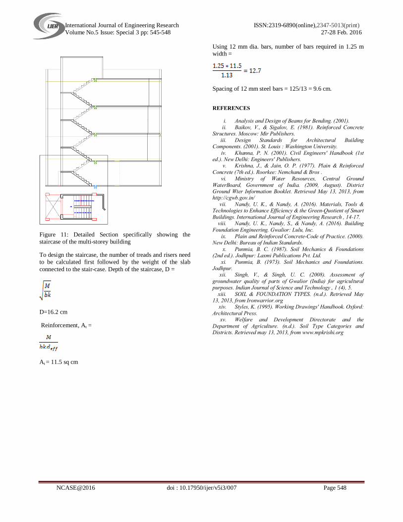
Figure 11: Detailed Section specifically showing the staircase of the multi-storey building
To design the staircase, the number of treads and risers need to be calculated first followed by the weight of the slab connected to the stair-case. Depth of the staircase, D =
D=16.2 cm
Reinforcement, At =
At = 11.5 sq cm
Using 12 mm dia. bars, number of bars required in 1.25 m width =
Spacing of 12 mm steel bars = 125/13 = 9.6 cm.
REFERENCES
i. Analysis and Design of Beams for Bending. (2001). ii. Baikov, V., & Sigalov, E. (1981). Reinforced Concrete
Structures. Moscow: Mir Publishers. iii. Design Standards for Architectural Building
Components. (2001). St. Louis : Washington University. iv. Khanna, P. N. (2001). Civil Engineers' Handbook (1st
ed.). New Delhi: Engineers' Publishers. v. Krishna, J., & Jain, O. P. (1977). Plain & Reinforced
Concrete (7th ed.). Roorkee: Nemchand & Bros . vi. Ministry of Water Resources, Central Ground
WaterBoard, Government of India. (2009, August). District Ground Wter Information Booklet. Retrieved May 13, 2013, from http://cgwb.gov.in/
vii. Nandy, U. K., & Nandy, A. (2016). Materials, Tools & Technologies to Enhance Efficiency & the Green-Quotient of Smart Buildings. International Journal of Engineering Research , 14-17.
viii. Nandy, U. K., Nandy, S., & Nandy, A. (2016). Building Foundation Engineering. Gwalior: Lulu, Inc.
ix. Plain and Reinforced Concrete-Code of Practice. (2000). New Delhi: Bureau of Indian Standards.
x. Punmia, B. C. (1987). Soil Mechanics & Foundations (2nd ed.). Jodhpur: Laxmi Publications Pvt. Ltd.
xi. Punmia, B. (1973). Soil Mechanics and Foundations. Jodhpur.
xii. Singh, V., & Singh, U. C. (2008). Assessment of groundwater quality of parts of Gwalior (India) for agricultural purposes. Indian Journal of Science and Technology , 1 (4), 5.
xiii. SOIL & FOUNDATION TYPES. (n.d.). Retrieved May 13, 2013, from Ironwarrior.org
xiv. Styles, K. (1995). Working Drawings' Handbook. Oxford: Architectural Press.
xv. Welfare and Development Directorate and the Department of Agriculture. (n.d.). Soil Type Categories and Districts. Retrieved may 13, 2013, from www.mpkrishi.org