Embed Size (px)
Citation preview
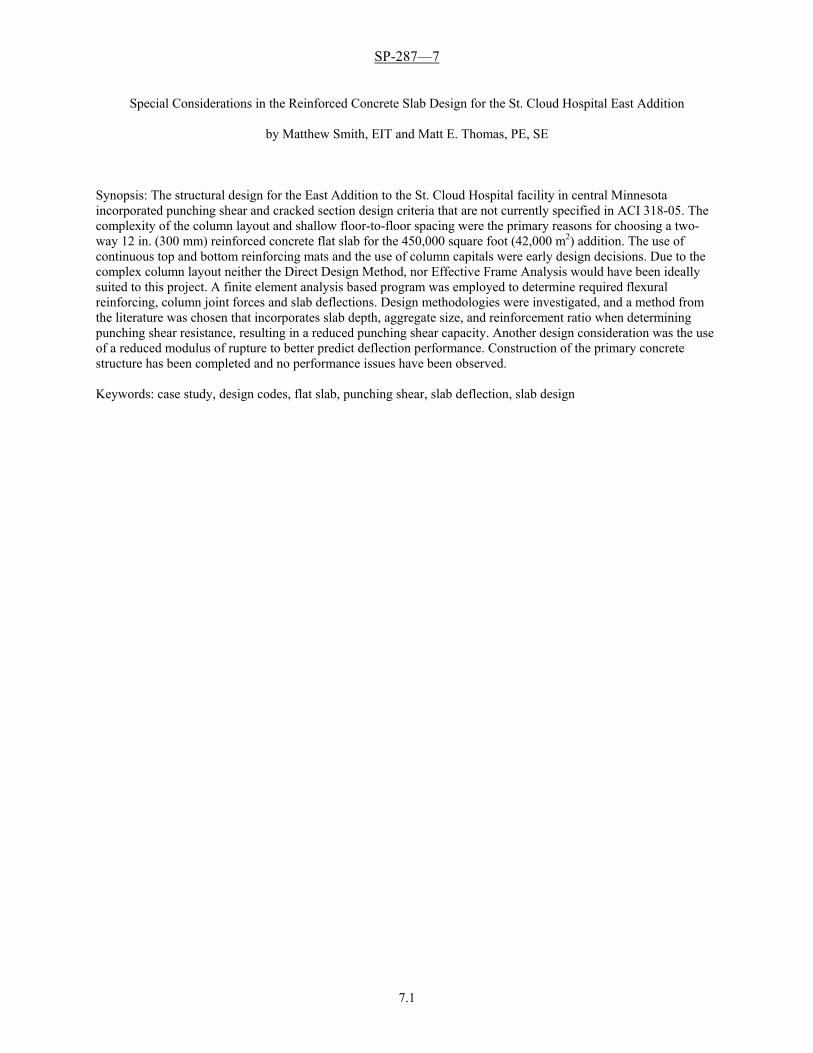
SP-287—7
7.1
Special Considerations in the Reinforced Concrete Slab Design for the St. Cloud Hospital East Addition
by Matthew Smith, EIT and Matt E. Thomas, PE, SE
Synopsis: The structural design for the East Addition to the St. Cloud Hospital facility in central Minnesota incorporated punching shear and cracked section design criteria that are not currently specified in ACI 318-05. The complexity of the column layout and shallow floor-to-floor spacing were the primary reasons for choosing a two-way 12 in. (300 mm) reinforced concrete flat slab for the 450,000 square foot (42,000 m2) addition. The use of continuous top and bottom reinforcing mats and the use of column capitals were early design decisions. Due to the complex column layout neither the Direct Design Method, nor Effective Frame Analysis would have been ideally suited to this project. A finite element analysis based program was employed to determine required flexural reinforcing, column joint forces and slab deflections. Design methodologies were investigated, and a method from the literature was chosen that incorporates slab depth, aggregate size, and reinforcement ratio when determining punching shear resistance, resulting in a reduced punching shear capacity. Another design consideration was the use of a reduced modulus of rupture to better predict deflection performance. Construction of the primary concrete structure has been completed and no performance issues have been observed. Keywords: case study, design codes, flat slab, punching shear, slab deflection, slab design
M. Smith and M. E. Thomas
7.2
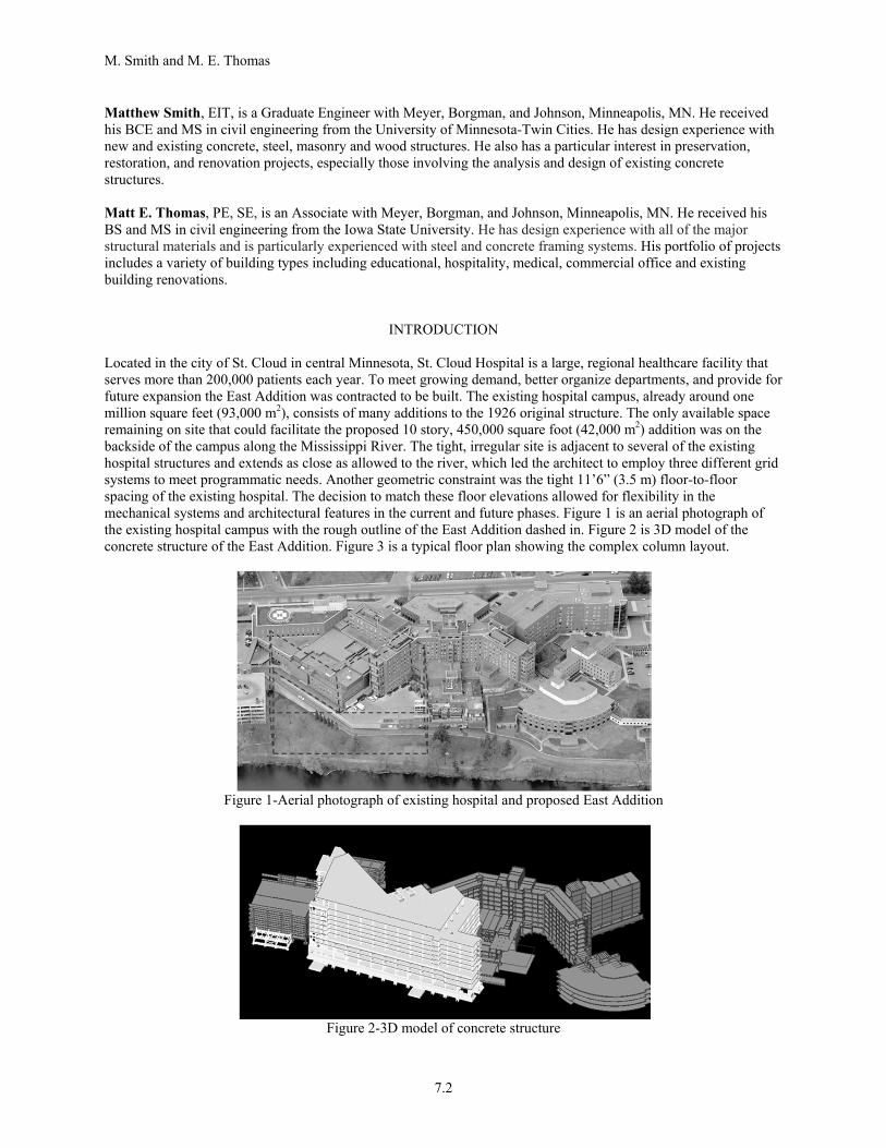
Matthew Smith, EIT, is a Graduate Engineer with Meyer, Borgman, and Johnson, Minneapolis, MN. He received his BCE and MS in civil engineering from the University of Minnesota-Twin Cities. He has design experience with new and existing concrete, steel, masonry and wood structures. He also has a particular interest in preservation, restoration, and renovation projects, especially those involving the analysis and design of existing concrete structures. Matt E. Thomas, PE, SE, is an Associate with Meyer, Borgman, and Johnson, Minneapolis, MN. He received his BS and MS in civil engineering from the Iowa State University. He has design experience with all of the major structural materials and is particularly experienced with steel and concrete framing systems. His portfolio of projects includes a variety of building types including educational, hospitality, medical, commercial office and existing building renovations.
INTRODUCTION Located in the city of St. Cloud in central Minnesota, St. Cloud Hospital is a large, regional healthcare facility that serves more than 200,000 patients each year. To meet growing demand, better organize departments, and provide for future expansion the East Addition was contracted to be built. The existing hospital campus, already around one million square feet (93,000 m2), consists of many additions to the 1926 original structure. The only available space remaining on site that could facilitate the proposed 10 story, 450,000 square foot (42,000 m2) addition was on the backside of the campus along the Mississippi River. The tight, irregular site is adjacent to several of the existing hospital structures and extends as close as allowed to the river, which led the architect to employ three different grid systems to meet programmatic needs. Another geometric constraint was the tight 11’6” (3.5 m) floor-to-floor spacing of the existing hospital. The decision to match these floor elevations allowed for flexibility in the mechanical systems and architectural features in the current and future phases. Figure 1 is an aerial photograph of the existing hospital campus with the rough outline of the East Addition dashed in. Figure 2 is 3D model of the concrete structure of the East Addition. Figure 3 is a typical floor plan showing the complex column layout.
Figure 1-Aerial photograph of existing hospital and proposed East Addition
Figure 2-3D model of concrete structure

Recent Development in Reinforced Concrete Slab Analysis, Design, and Serviceability
7.3
Figure 3-Typical East Addition floor plan
Given the short floor-to-floor height and the complex column layout that resulted from the multiple grid systems, a two-way reinforced concrete flat slab was chosen as the structural system. It minimized the structural depth while eliminating the need to develop a complex beam or joist layout. Given the 26 by 30 ft. (7.9 by 9.1 m) maximum bay size a 12 in. (300 mm) thick concrete slab was chosen for the general hospital floors which was increased to 13 in. (330 mm) for the higher loads at the mechanical levels. However, the design slab thickness was effectively 10 in. (250 mm) in many areas due to the presence of slab depressions required for bathroom finishes. The selection of the concrete flat slab allowed more room for mechanical systems and higher ceilings than other concrete or steel framing systems. Post-tensioned concrete slabs were considered, but concerns about future flexibility drove the decision away from post-tensioning.
EARLY DESIGN DECISIONS In addition to the selection of the reinforced concrete flat slab, there were other early design decisions that were driven by the constraints of the project and previous design experience. Concrete beams were provided along most of the edges of the building. This lessened many of the disadvantages of a flat slab structure without restricting the open space needed for the mechanical systems in the interior of the floor plate. The increased depth at the edge allowed for easier attachments for the cladding supports and greatly reduced deflection for deflection sensitive cladding elements such as brick. The stiffened edge also reduced the exterior mid-bay deflections and positive moments and the first interior bay negative moment. The presence of the edge beams and their shear reinforcing also eliminated punching shear as a design consideration at the edge columns, which have the most eccentric shear loads. One notable exception to the use of concrete edge beams was along the existing hospital buildings where a 10 to 12 foot (3.0 to 3.7 m) long slab cantilever was employed to hold the new columns and foundations back away from the existing buildings. This was done to reduce conflicts with the existing footings and reduce costly underpinning. The slabs were detailed with an 18 in. (460 mm) wide pour strip along the existing buildings, which allowed for the existing exterior to remain in place until the new concrete structure was entirely completed. The pour strip was tied to the previous slab pours with rebar dowels and a continuous shear key, and it was also supported by the existing columns via steel haunch connections that allowed horizontal movement. The slab cantilever and delayed pour strip combined to reduce the load placed on the existing structure while still ensuring no differential vertical displacement between the new and existing floors. Given the irregular column layout, continuous two-way top and bottom reinforcing was detailed. It was expected that the economy gain in design, documentation, detailing, placement and inspection would offset the cost of the reinforcing steel that was provided beyond the minimum required to meet strength criteria alone. This approach should also reduce the long-term deflection of the slabs via the code allowed reduction in creep effect of 15% for the typical reinforcing ratio.
M. Smith and M. E. Thomas
7.4
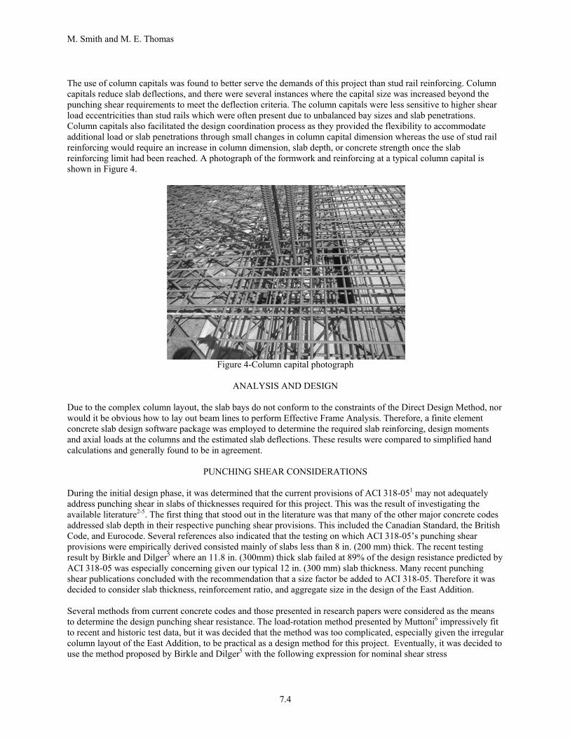
The use of column capitals was found to better serve the demands of this project than stud rail reinforcing. Column capitals reduce slab deflections, and there were several instances where the capital size was increased beyond the punching shear requirements to meet the deflection criteria. The column capitals were less sensitive to higher shear load eccentricities than stud rails which were often present due to unbalanced bay sizes and slab penetrations. Column capitals also facilitated the design coordination process as they provided the flexibility to accommodate additional load or slab penetrations through small changes in column capital dimension whereas the use of stud rail reinforcing would require an increase in column dimension, slab depth, or concrete strength once the slab reinforcing limit had been reached. A photograph of the formwork and reinforcing at a typical column capital is shown in Figure 4.
Figure 4-Column capital photograph
ANALYSIS AND DESIGN
Due to the complex column layout, the slab bays do not conform to the constraints of the Direct Design Method, nor would it be obvious how to lay out beam lines to perform Effective Frame Analysis. Therefore, a finite element concrete slab design software package was employed to determine the required slab reinforcing, design moments and axial loads at the columns and the estimated slab deflections. These results were compared to simplified hand calculations and generally found to be in agreement.
PUNCHING SHEAR CONSIDERATIONS During the initial design phase, it was determined that the current provisions of ACI 318-051 may not adequately address punching shear in slabs of thicknesses required for this project. This was the result of investigating the available literature2-5. The first thing that stood out in the literature was that many of the other major concrete codes addressed slab depth in their respective punching shear provisions. This included the Canadian Standard, the British Code, and Eurocode. Several references also indicated that the testing on which ACI 318-05’s punching shear provisions were empirically derived consisted mainly of slabs less than 8 in. (200 mm) thick. The recent testing result by Birkle and Dilger5 where an 11.8 in. (300mm) thick slab failed at 89% of the design resistance predicted by ACI 318-05 was especially concerning given our typical 12 in. (300 mm) slab thickness. Many recent punching shear publications concluded with the recommendation that a size factor be added to ACI 318-05. Therefore it was decided to consider slab thickness, reinforcement ratio, and aggregate size in the design of the East Addition. Several methods from current concrete codes and those presented in research papers were considered as the means to determine the design punching shear resistance. The load-rotation method presented by Muttoni6 impressively fit to recent and historic test data, but it was decided that the method was too complicated, especially given the irregular column layout of the East Addition, to be practical as a design method for this project. Eventually, it was decided to use the method proposed by Birkle and Dilger5 with the following expression for nominal shear stress
Recent Development in Reinforced Concrete Slab Analysis, Design, and Serviceability
7.5
150′ ∙
/
2 ′
In metric
16′ ∙
/
0.17 ′
where f’c is the specified compressive strength in psi (MPa), ρ is the reinforcement ratio, and d is the effective depth in in. (mm). This method was chosen because it accounted for both the size factor and reinforcement ratio and was simple to apply to the design of a large structure where the punching shear requirements varied greatly from column to column. The information presented by Birkle and Dilger also showed that this equation reasonably accounted for the effect of depth for the 11.8 in. (300mm) thick slab tested. This expression does not include aggregate size as some of the other methods proposed. For this project a 1½ in. (37.5 mm) maximum nominal aggregate size was specified to improve punching shear performance. However no attempt to quantify this benefit was attempted in design. The use of larger aggregate was also driven by a desire to reduce concrete shrinkage and the associated cracking. The authors’ firm often specifies well-graded aggregate concrete mixes with as large an aggregate size as is practical for the structural element. For the typical 12 in. (300 mm) thick slab areas with an effective depth of 10 in. (250 mm), a reinforcement ratio of 0.73%, and a specified concrete strength of 6,000 psi (40MPa), was used for all structural slabs in the design of the
East Addition. The incorporation of this additional provision reduced the design shear stress to 3.1 ′psi
(0.26 ′MPa). This is a 23% reduction compared to what would otherwise be calculated using ACI 318-05. When the punching shear demand exceeded this limit, the applied stress was reduced by increasing the dimensions of the column capital or the design shear stress capacity was increased by increasing the reinforcing ratio. In this case,
increasing the reinforcing ratio to 1.10% increased the design shear stress to 3.6 ′ (0.30 ′MPa). In no case was a
design shear stress higher than 4 ′psi (0.33 ′MPa) allowed to respect the current requirements of ACI 318-05. Punching shear design example The following is a design example to show how the additional size affect considerations were incorporated into the design process. The structural slab concrete strength was 6,000 psi (40MPa), the effective depth was 10 in. (250 mm), and the slab reinforcing was #6 at 6 in. OC (#19 at 150mm OC) resulting in a reinforcement ratio of 0.73%. The standard column capital size was 45 by 45 in. (1.1 by 1.1 m) which could generally be increased to 60 by 60 in. (1.5 by 1.5 m) if needed. The depth of the column capitals will be set to not control the design. The loads transferred at the column-slab interface were Vu = 375k (1700kN), Mux = 150ft-k (200kN*m), and Muy = 100ft-k (140kN*m). Design shear stress:
150′ ∙
1506000 ∙ 0.0073
10 .245 1.7
2 ′ 4 ′ 155 1.1 310 2.1 OK
0.75 184 1.3
Geometric properties: 45 . 55 . 1.4
4 220 . 5.6
623
1.12 10 . 4.7 10
11
10.40
M. Smith and M. E. Thomas
7.6
Factored shear stress:
170 30 200 1.4 N.G.
In this case the factored shear stress was above the design shear stress. This was typically addressed in one of two ways. The first was to increase the slab reinforcing to increase the design shear stress. This is shown in Option A below where the slab reinforcement was increased to #6 at 4in. OC (#19 at 100mm OC) resulting in a reinforcement ratio of 1.1%. The second option would be to use the larger column capital size to reduce the factored shear stress as shown below in Option B. However, without the added size affect considerations ACI 318-05 would have allowed a design shear stress of 232 psi (1.6 MPa), and the design would have been considered satisfactory as is. Option A: Increased slab reinforcing
281 1.9 155 1.1 310 2.1 OK
211 1.5 200 1.4 OK
Option B: Larger column capital 70. 1.8 ; 280 . 7.1 2.30 10 . 9.6 10
134 18 152 1.0 184 1.3 OK
ESTIMATED SLAB DEFLECTIONS During the schematic design phase, it was considered that the slab deflections predicted by the finite element analysis software underestimated the effects of loss of stiffness due to cracking. The cracked deflection analysis resulted in only an 8% effective loss of stiffness at the largest interior deflection. The analysis software accounted for cracking by using the following effective stiffness expression from ACI 318-05
1
where Icr is the moment of inertia of cracked concrete section, Ig is the moment of inertia of gross concrete section, Mcr is the cracking moment, and Ma is the applied moment. Given that the cracked to applied moment ratio is cubed, the effective stiffness is sensitive to this ratio when it approaches unity. This was the case given the typical span, depth, and loading of the East Addition slabs, and a rational, simple approach to more conservatively estimate cracked slab deflections was sought out. The approach presented by Scanlon and Thompson7 of simply reducing the
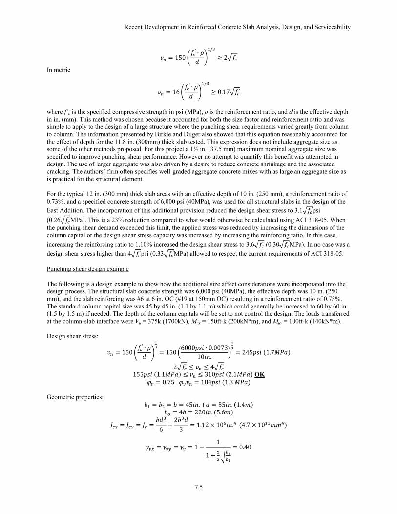
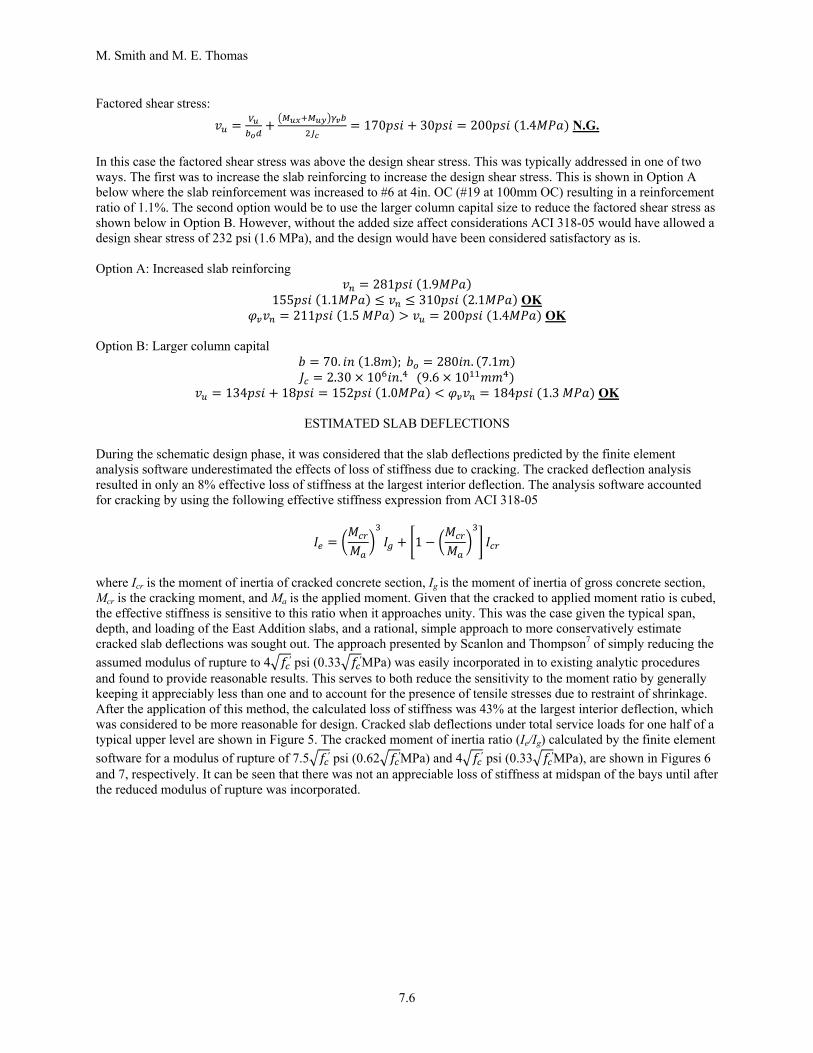
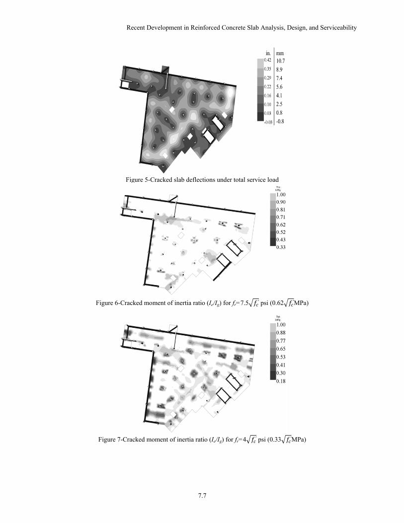
assumed modulus of rupture to 4 ′ psi (0.33 ′MPa) was easily incorporated in to existing analytic procedures and found to provide reasonable results. This serves to both reduce the sensitivity to the moment ratio by generally keeping it appreciably less than one and to account for the presence of tensile stresses due to restraint of shrinkage. After the application of this method, the calculated loss of stiffness was 43% at the largest interior deflection, which was considered to be more reasonable for design. Cracked slab deflections under total service loads for one half of a typical upper level are shown in Figure 5. The cracked moment of inertia ratio (Ie/Ig) calculated by the finite element
software for a modulus of rupture of 7.5 ′ psi (0.62 ′MPa) and 4 ′ psi (0.33 ′MPa), are shown in Figures 6 and 7, respectively. It can be seen that there was not an appreciable loss of stiffness at midspan of the bays until after the reduced modulus of rupture was incorporated.
Recent Development in Reinforced Concrete Slab Analysis, Design, and Serviceability
7.7
Figure 5-Cracked slab deflections under total service load
Figure 6-Cracked moment of inertia ratio (Ie/Ig) for fr=7.5 ′ psi (0.62 ′MPa)
Figure 7-Cracked moment of inertia ratio (Ie/Ig) for fr=4 ′ psi (0.33 ′MPa)
M. Smith and M. E. Thomas
7.8
CONCLUSIONS There is significant discussion in the literature with respect to adding a size effect factor for punching shear in concrete slabs. This consideration has not been added to ACI 318, as opposed to many of the other major concrete design codes. This leaves the decision on whether or not to include a size effect factor in the design of a thick concrete slab up to the structural engineer along with the more difficult decision of how to account for it if desired. In the design of the St. Cloud Hospital East Addition it was decided to include a size effect factor for punching shear. The method chosen was proposed by Birkle and Dilger and considered both effective depth and reinforcement ratio. Another non-codified provision used in the design of the slabs was a reduced modulus of rupture for cracked deflection analysis to account for shrinkage restraint stresses. The analytically determined deflections were found to be more reasonable with this reduced modulus of rupture as very little flexural cracking was initially predicted. The construction of the primary concrete structure was completed in January 2011 with an expected occupancy date of June 2012. The concrete slabs have been essentially load tested with 50 pounds per square foot (2.4 kN/m2) shoring loads during construction, and no performance issues have been observed.
REFERENCES
1. ACI Committee 318, “Building Code Requirements for Structural Concrete (ACI 318-05) and Commentary (ACI318R-05),” American Concrete Institute, Farmington Hills, MI, 2005.
2. Gardner, N.J., “ACI 318-05, CSA A23.3-04, Eurocode 2 (2004), DIN 1045-1 (2001), BS 8110-97 and CEB-FIP MC 90 Provisions for Punching Shear of Reinforced Concrete Flat Slabs,” ACI SP-232 Punching Shear in Reinforced Concrete Slabs, American Concrete Institute, Farmington Hills, MI, 2005, pp. 1-22.
3. Mitchell, D., Cook, W.D., and Dilger, W., “Effects of Size, Geometry and Material Properties on Punching Shear Resistance,” ACI SP-232 Punching Shear in Reinforced Concrete Slabs, American Concrete Institute, Farmington Hills, MI, 2005, pp. 39-56.
4. Dilger, W., Birkle, G., and Mitchell, D., “Effect of Flexural Reinforcement on Punching Shear Resistance,” ACI SP-232 Punching Shear in Reinforced Concrete Slabs, American Concrete Institute, Farmington Hills, MI, 2005, pp. 39-56.
5. Birkle, G. and Dilger, W. H. “Influence of Slab Thickness on Punching Shear Strength,” ACI Structural Journal, Vol. 105, No. 2, Mar.-Apr. 2008, American Concrete Institute, Farmington Hills, MI, pp. 180-188.
6. Muttoni, A., “Punching Shear Strength of Reinforced Concrete Slabs without Transverse Reinforcement,” ACI Structural Journal, Vol. 105, No. 4, Jul.-Aug. 2008, American Concrete Institute, Farmington Hills, MI, pp. 440-450.
7. Scanlon, A. and Thompson, D. P., “Evaluation of ACI 318 Requirements for Control of Two-Way Slab Deflections,” ACI Structural Journal, Vol. 87, No. 6, Nov.-Dec. 2008, American Concrete Institute, Farmington Hills, MI, pp. 657-661.