Embed Size (px)
Citation preview
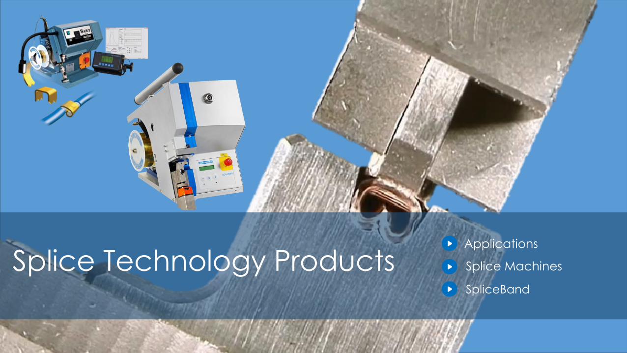
Splice Technology Products Splice Machines
Applications
SpliceBand
2
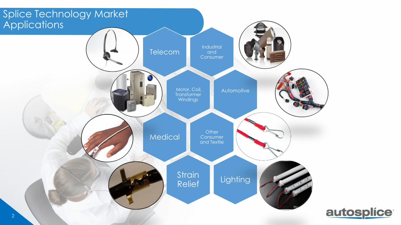
Splice Technology Market Applications
Industrial and
ConsumerTelecom
Motor, Coil, Transformer
Windings
Automotive
Other Consumer and Textile
Medical
Strain Relief
Lighting
4
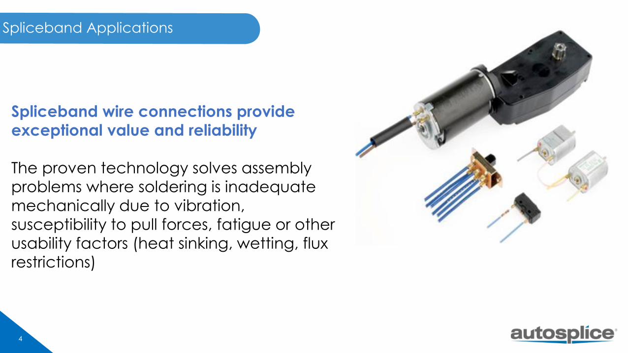
Spliceband Applications
Spliceband wire connections provide
exceptional value and reliability
The proven technology solves assembly
problems where soldering is inadequate
mechanically due to vibration,
susceptibility to pull forces, fatigue or other
usability factors (heat sinking, wetting, flux
restrictions)
5
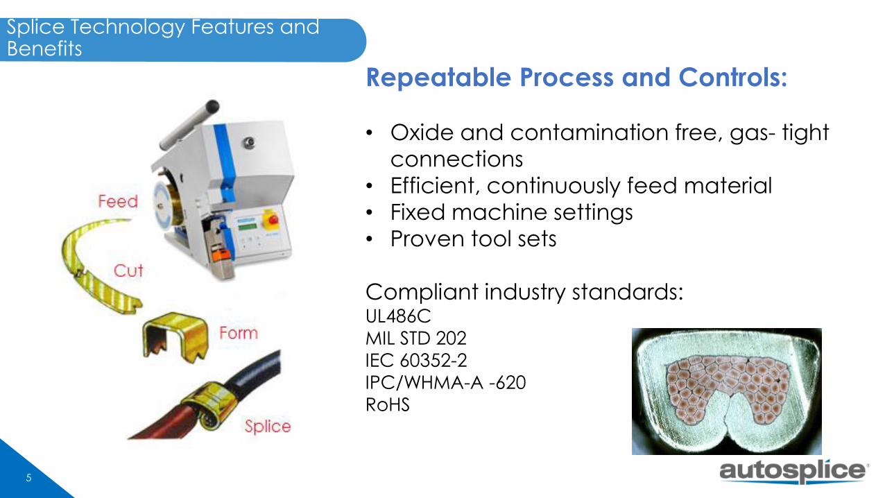
Repeatable Process and Controls:
• Oxide and contamination free, gas- tight
connections
• Efficient, continuously feed material
• Fixed machine settings
• Proven tool sets
Compliant industry standards:UL486C
MIL STD 202
IEC 60352-2
IPC/WHMA-A -620
RoHS
Splice Technology Features and Benefits
6
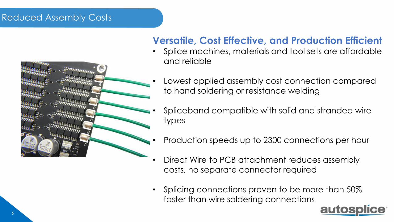
Reduced Assembly Costs
Versatile, Cost Effective, and Production Efficient• Splice machines, materials and tool sets are affordable
and reliable
• Lowest applied assembly cost connection compared
to hand soldering or resistance welding
• Spliceband compatible with solid and stranded wire
types
• Production speeds up to 2300 connections per hour
• Direct Wire to PCB attachment reduces assembly
costs, no separate connector required
• Splicing connections proven to be more than 50%
faster than wire soldering connections
7
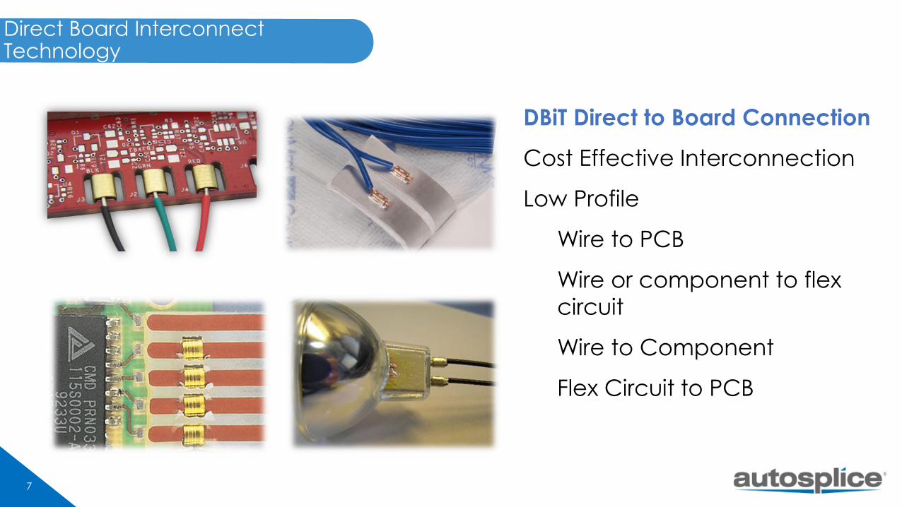
Direct Board Interconnect Technology
DBiT Direct to Board Connection
Cost Effective Interconnection
Low Profile
Wire to PCB
Wire or component to flex
circuit
Wire to Component
Flex Circuit to PCB
8
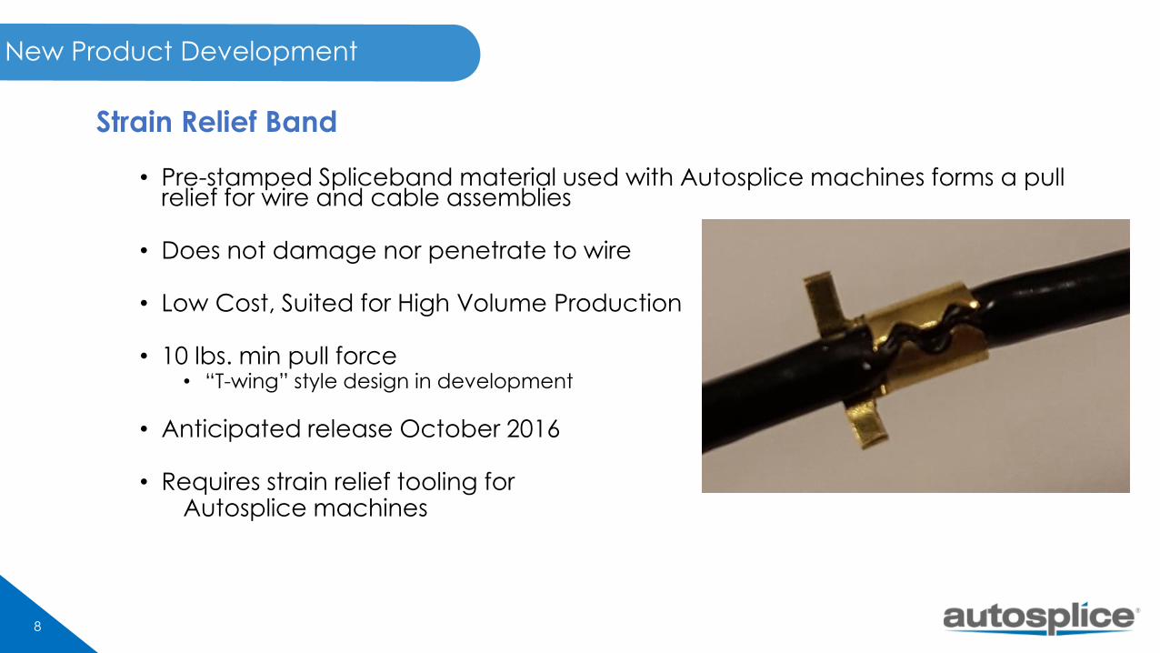
New Product Development
Strain Relief Band
• Pre-stamped Spliceband material used with Autosplice machines forms a pull relief for wire and cable assemblies
• Does not damage nor penetrate to wire
• Low Cost, Suited for High Volume Production
• 10 lbs. min pull force • “T-wing” style design in development
• Anticipated release October 2016
• Requires strain relief tooling forAutosplice machines
9
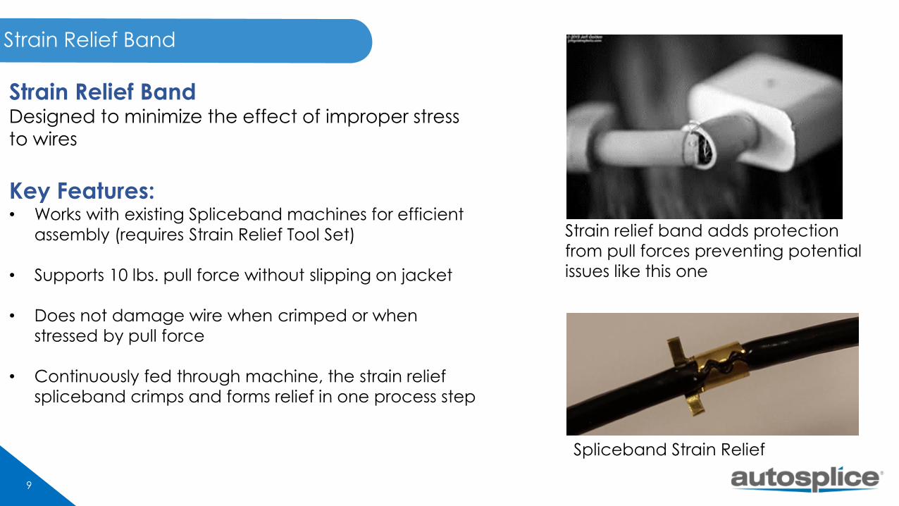
Strain Relief Band
Strain Relief Band Designed to minimize the effect of improper stress to wires
Key Features:• Works with existing Spliceband machines for efficient
assembly (requires Strain Relief Tool Set)
• Supports 10 lbs. pull force without slipping on jacket
• Does not damage wire when crimped or when
stressed by pull force
• Continuously fed through machine, the strain relief
spliceband crimps and forms relief in one process step
Strain relief band adds protection
from pull forces preventing potential
issues like this one
Spliceband Strain Relief
10
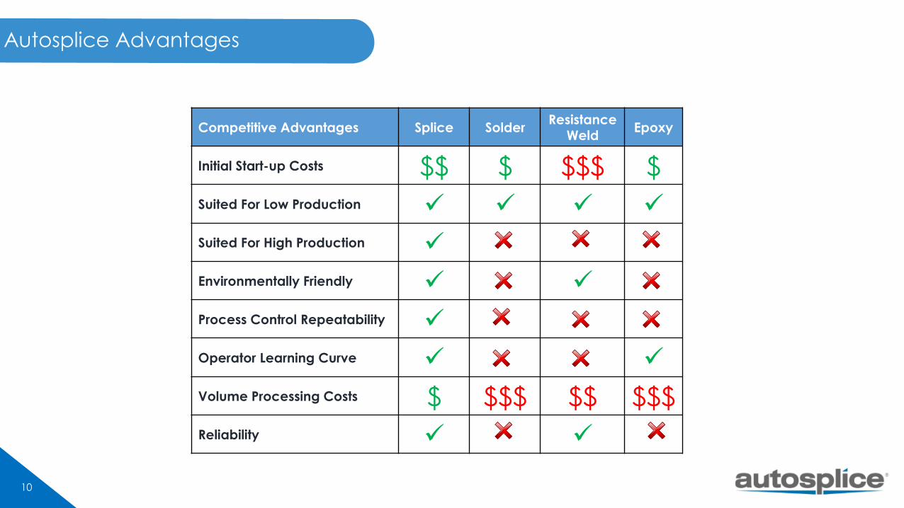
Autosplice Advantages
Competitive Advantages Splice Solder Resistance
WeldEpoxy
Initial Start-up Costs $$ $ $$$ $
Suited For Low Production
Suited For High Production
Environmentally Friendly
Process Control Repeatability
Operator Learning Curve
Volume Processing Costs $ $$$ $$ $$$
Reliability
12
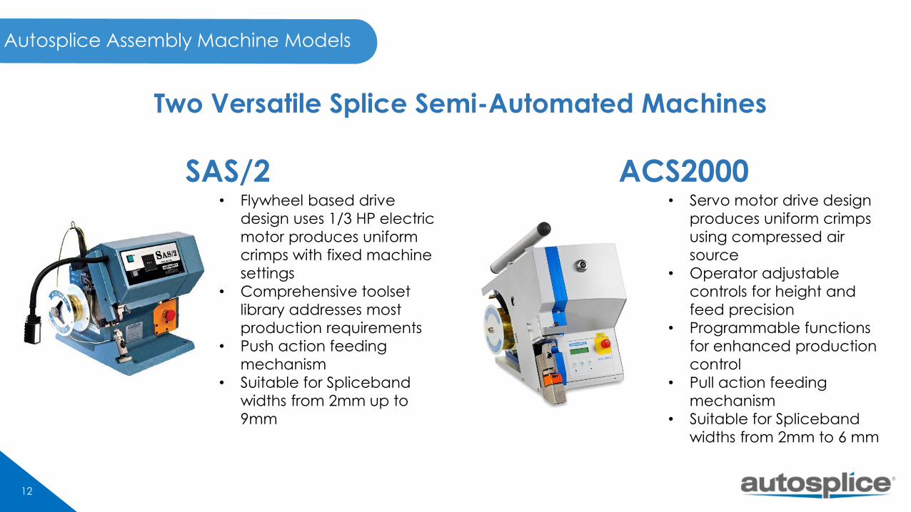
Autosplice Assembly Machine Models
Two Versatile Splice Semi-Automated Machines
• Servo motor drive design
produces uniform crimps
using compressed air
source
• Operator adjustable
controls for height and
feed precision
• Programmable functions
for enhanced production
control
• Pull action feeding
mechanism
• Suitable for Spliceband
widths from 2mm to 6 mm
• Flywheel based drive
design uses 1/3 HP electric
motor produces uniform
crimps with fixed machine
settings
• Comprehensive toolset
library addresses most
production requirements
• Push action feeding
mechanism
• Suitable for Spliceband
widths from 2mm up to
9mm
SAS/2 ACS2000
13
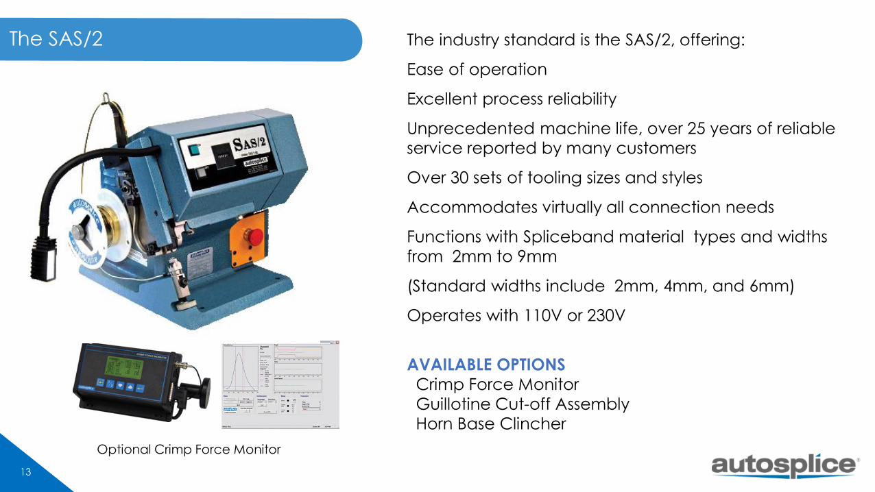
The industry standard is the SAS/2, offering:
Ease of operation
Excellent process reliability
Unprecedented machine life, over 25 years of reliable
service reported by many customers
Over 30 sets of tooling sizes and styles
Accommodates virtually all connection needs
Functions with Spliceband material types and widths
from 2mm to 9mm
(Standard widths include 2mm, 4mm, and 6mm)
Operates with 110V or 230V
AVAILABLE OPTIONS
Crimp Force Monitor
Guillotine Cut-off Assembly
Horn Base Clincher
Optional Crimp Force Monitor
The SAS/2

14
The ACS2000 advances 40 years of SAS Splicing
expertise and technology into an economical
and efficient Splicing system.
Large range of available tool sizes enables an
almost unlimited options of applications.
The rapid change tooling minimizes set-up time
between application changeovers.
Programmable production counters.
Functions with Spliceband material widths of
2mm, 4mm and 6mm (1mm in development)
110V or 230V
87Psi
AVAILABLE OPTIONSCrimp Force Monitor
Guillotine Cut-off Assembly
Horn Base Clincher
The ACS2000
Optional Crimp Force Monitor
15
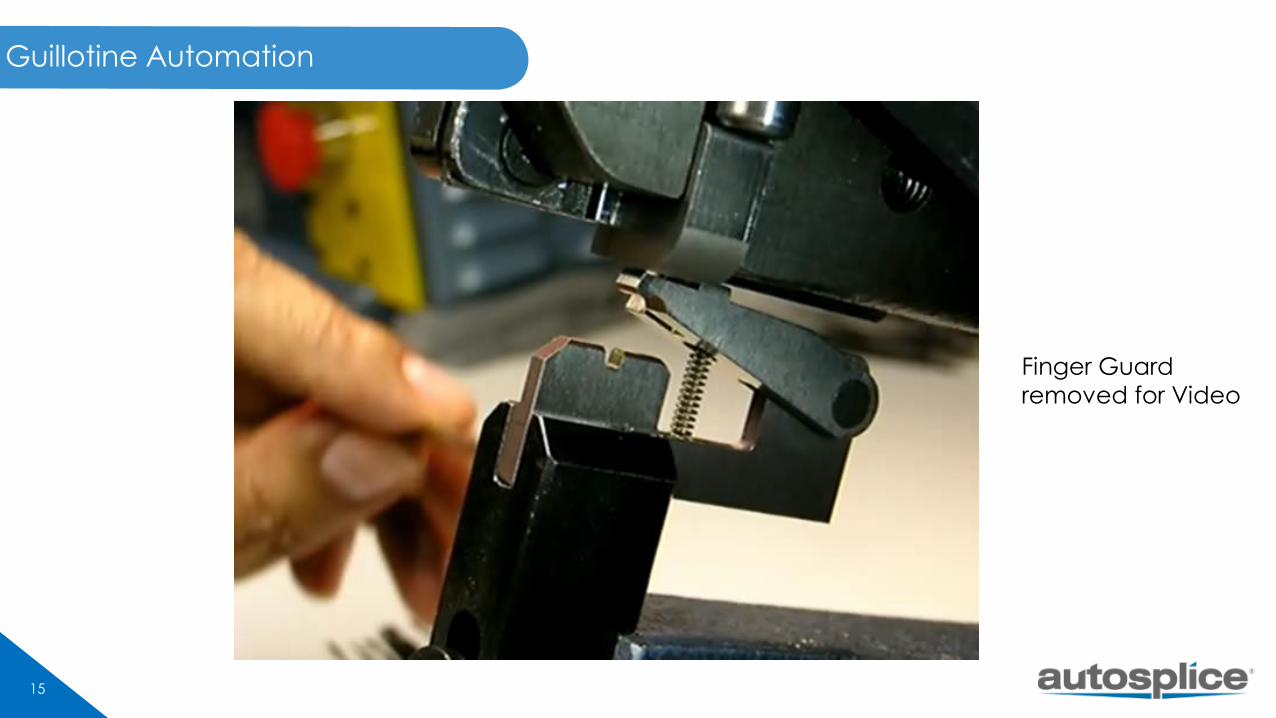
Guillotine Automation
Finger Guard
removed for Video
16
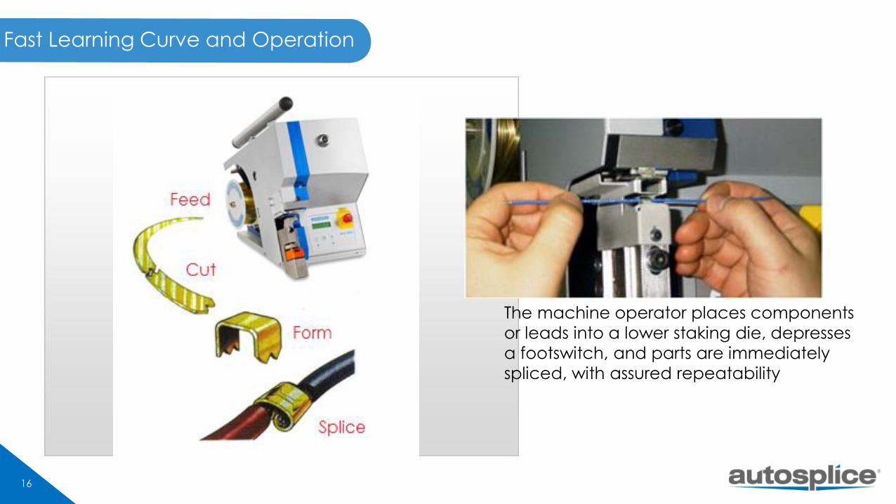
Fast Learning Curve and Operation
The machine operator places components
or leads into a lower staking die, depresses
a footswitch, and parts are immediately
spliced, with assured repeatability
17
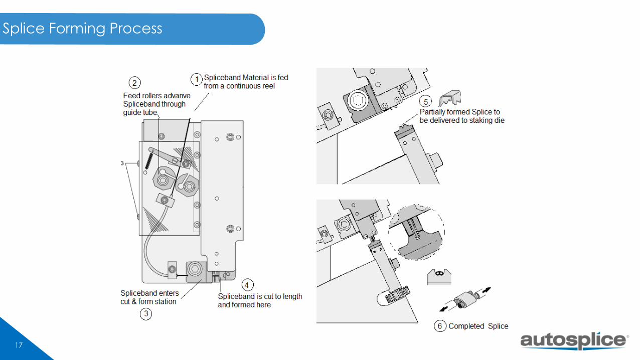
Splice Forming Process
18
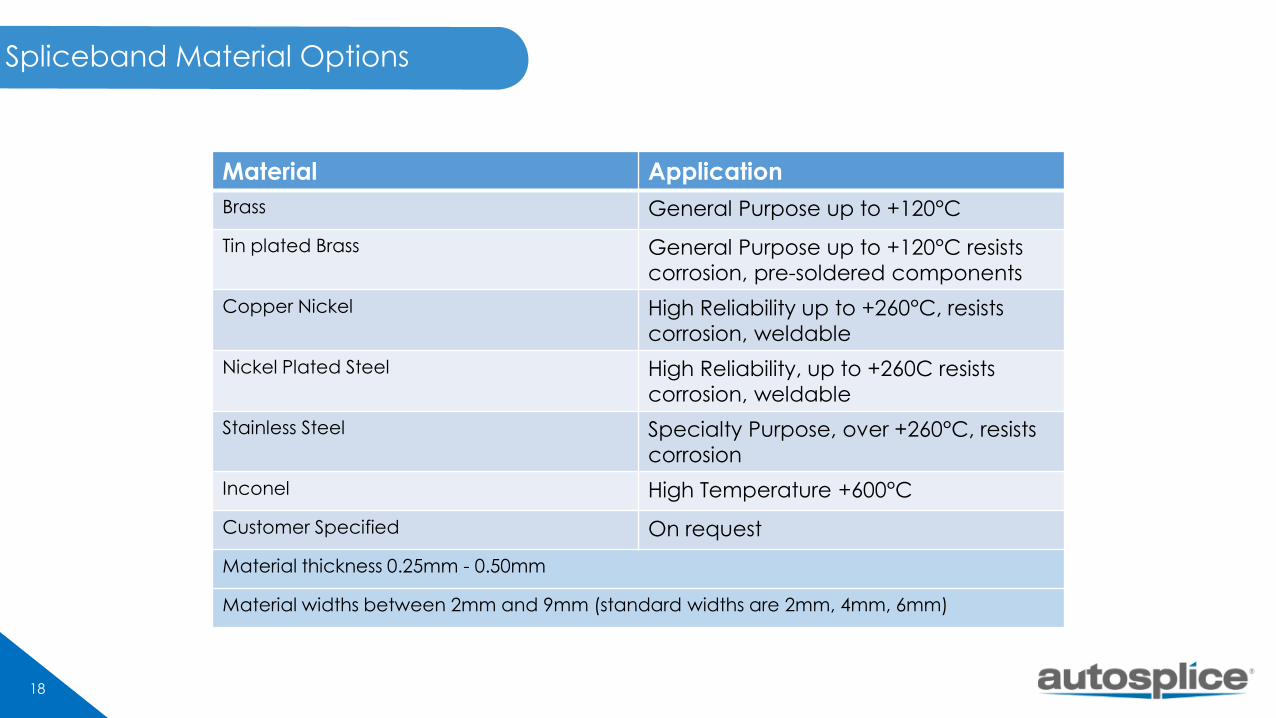
Spliceband Material Options
Material Application
Brass General Purpose up to +120°C
Tin plated Brass General Purpose up to +120°C resists
corrosion, pre-soldered components
Copper Nickel High Reliability up to +260°C, resists
corrosion, weldable
Nickel Plated Steel High Reliability, up to +260C resists
corrosion, weldable
Stainless Steel Specialty Purpose, over +260°C, resists
corrosion
Inconel High Temperature +600°C
Customer Specified On request
Material thickness 0.25mm - 0.50mm
Material widths between 2mm and 9mm (standard widths are 2mm, 4mm, 6mm)
19
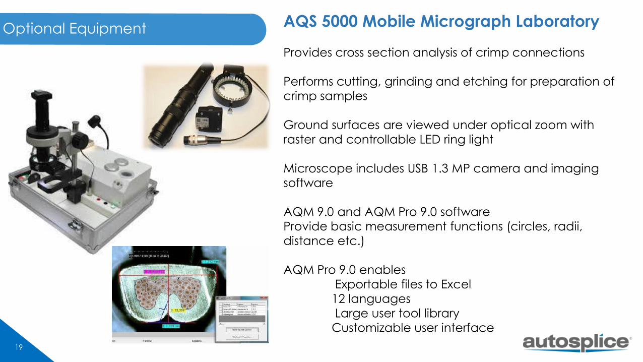
Optional Equipment AQS 5000 Mobile Micrograph Laboratory
Provides cross section analysis of crimp connections
Performs cutting, grinding and etching for preparation of
crimp samples
Ground surfaces are viewed under optical zoom with
raster and controllable LED ring light
Microscope includes USB 1.3 MP camera and imaging
software
AQM 9.0 and AQM Pro 9.0 software
Provide basic measurement functions (circles, radii,
distance etc.)
AQM Pro 9.0 enables
Exportable files to Excel
12 languages
Large user tool library
Customizable user interface

20
Crimp Force Monitor
CFM 4000 Crimp Force Monitor option for the SAS/2 and
ACS2000 Machines
Production Quality Monitoring for Detection of:
• Incorrect strip length
• Missing strands
• Incorrect wire cross-section
• Incorrect terminal
• Inconsistent terminal material
• Insulation in wire crimp
• Incorrect insertion depth
• Incorrect crimp height
21
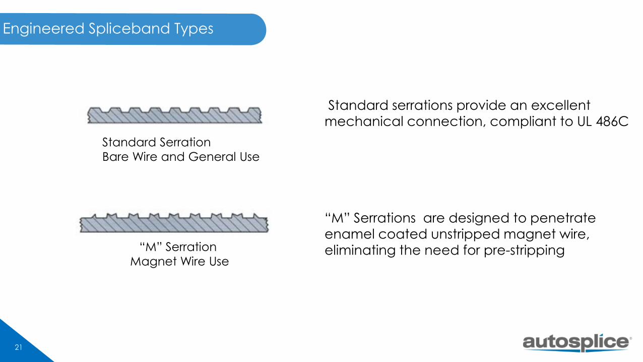
Engineered Spliceband Types
Standard Serration
Bare Wire and General Use
“M” Serration
Magnet Wire Use
Standard serrations provide an excellent
mechanical connection, compliant to UL 486C
“M” Serrations are designed to penetrate
enamel coated unstripped magnet wire,
eliminating the need for pre-stripping
22
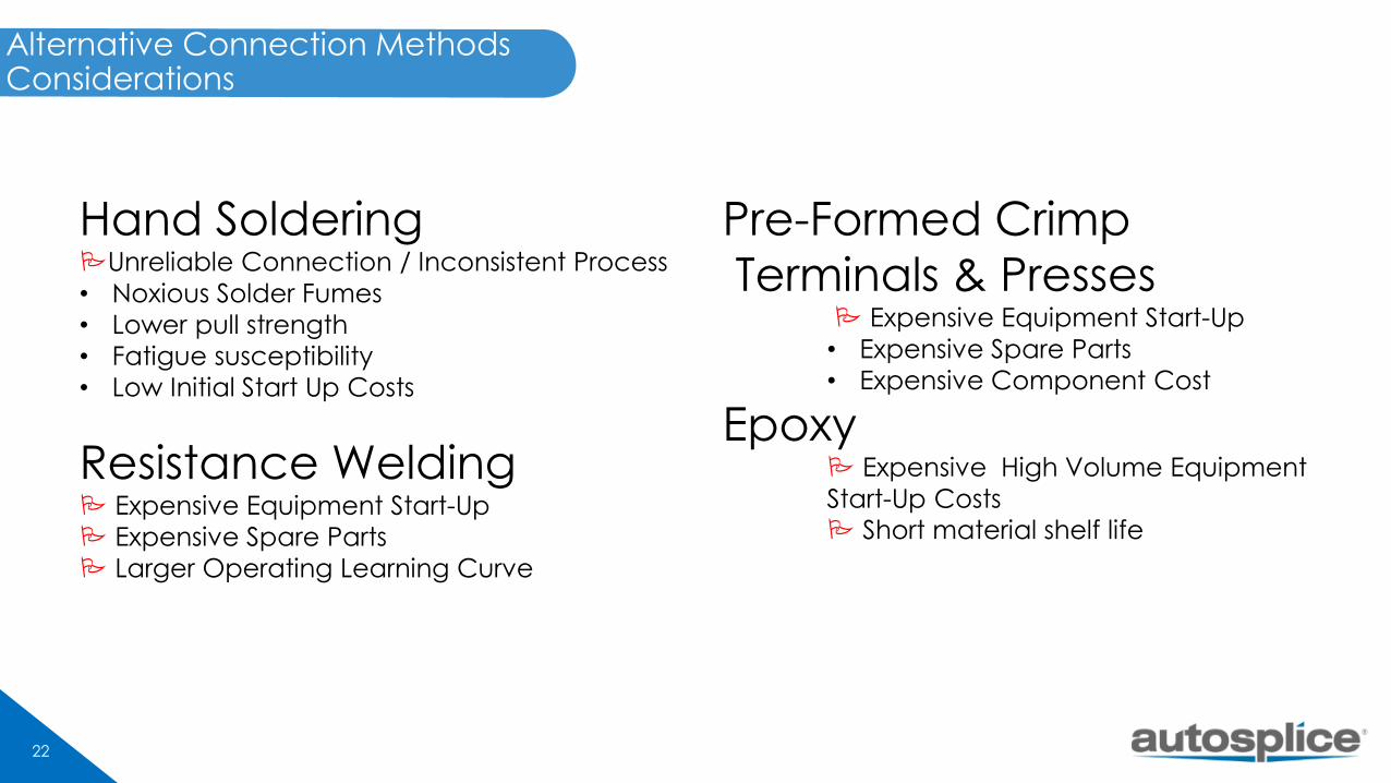
Alternative Connection Methods Considerations
Hand SolderingUnreliable Connection / Inconsistent Process
• Noxious Solder Fumes
• Lower pull strength
• Fatigue susceptibility
• Low Initial Start Up Costs
Resistance Welding Expensive Equipment Start-Up
Expensive Spare Parts
Larger Operating Learning Curve
Pre-Formed Crimp
Terminals & Presses Expensive Equipment Start-Up
• Expensive Spare Parts
• Expensive Component Cost
Epoxy Expensive High Volume Equipment
Start-Up Costs Short material shelf life
23
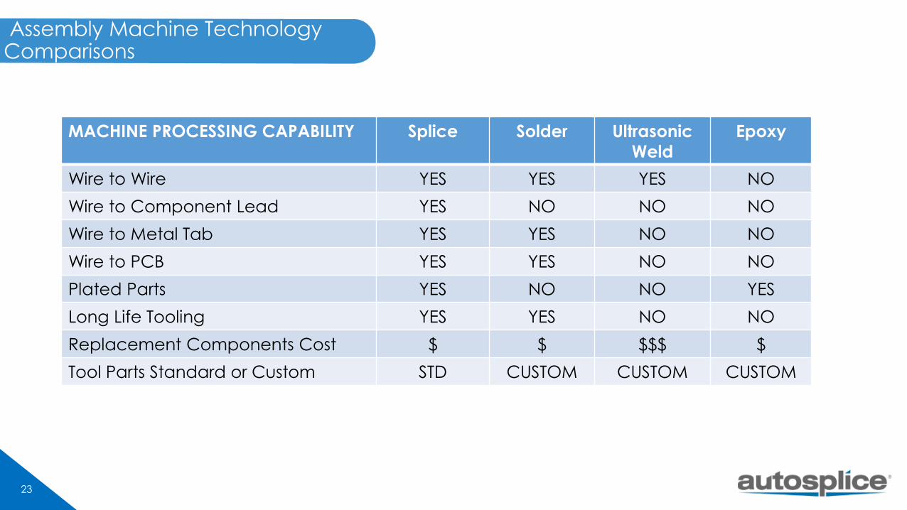
Assembly Machine Technology Comparisons
MACHINE PROCESSING CAPABILITY Splice Solder Ultrasonic
Weld
Epoxy
Wire to Wire YES YES YES NO
Wire to Component Lead YES NO NO NO
Wire to Metal Tab YES YES NO NO
Wire to PCB YES YES NO NO
Plated Parts YES NO NO YES
Long Life Tooling YES YES NO NO
Replacement Components Cost $ $ $$$ $
Tool Parts Standard or Custom STD CUSTOM CUSTOM CUSTOM
24
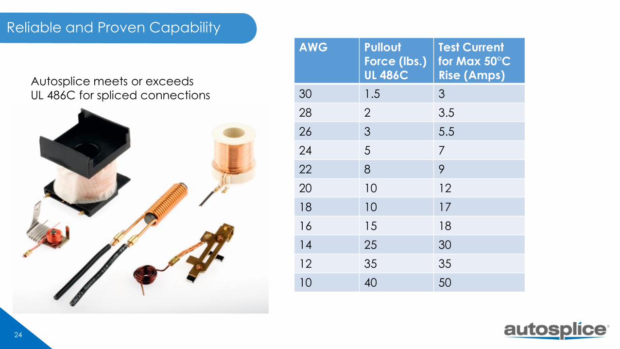
Reliable and Proven Capability
AWG Pullout
Force (lbs.)
UL 486C
Test Current
for Max 50°C
Rise (Amps)
30 1.5 3
28 2 3.5
26 3 5.5
24 5 7
22 8 9
20 10 12
18 10 17
16 15 18
14 25 30
12 35 35
10 40 50
Autosplice meets or exceeds
UL 486C for spliced connections