Embed Size (px)
Citation preview

APPLICATION OF INTRANET TECHNOLOGIES FOR POWER SYSTEM PROTECTION
A. TAKEUCHI F. KUMURA M. NAKAHARA Chubu Electric Power Co. Kansai Electric Power Co. Kyushu Electric Power Co.
T. YOSHIZUMI M. USUI T. MATSUSHIMA* Hitachi Ltd. TMT&D Corporation TMT&D Corporation
(Japan) SUMMARY Among recent active technical innovations, the progress of data transmission technologies has been marked, particularly in the field of internet/intranet technologies. These innovations have also rapidly been applied, in recent years, to the power system protection and control area. At the same time, promotion of efficiency in the field of power system protection and control is a major topic that have been facing for many years. Expanding intranet technology will play a significant role in the promotion of this long-term goal for greater efficiency. Remote operation and monitoring of the protection relay from the station are easily realized by intranet use. Through this system, greater maintenance cost benefits are expected because many protection relays over a wide area can be monitored and controlled without leaving the maintenance station. In this system not only monitoring but also testing of relays from the remote station is possible using an “agent technique”. Though intranet/internet technologies have great potential, security against external threats is an inevitable problem in applying such technologies. In this paper, the basic philosophy and various security techniques are also described. Keywords: Intranet - Internet - Remote Operation - Remote Monitoring - Protection - Control - Maintenance Cost - Agent - Security 1. INTRODUCTION The power industry in Japan has been actively introducing IT technologies with the aim of improving the efficiency of business management and increasing the additional value of customer service before the industry-wide deregulation of the electricity sector. The implementation of IT in the power industry is evident in material procurement areas such as data management, customer’ power transaction rates, and electronic bidding. One good example is the power transmission sector, where the IT technologies are applied to the substation automation and to the protection systems aiming to improve operational efficiency. Specific issues related to improvement on operational efficiency include facility information operations such as power system fault, equipment failure, and inspection-related information; maintenance planning such as the improvement, repair and inspection of the facilities; maintenance operations to put these plans into practice; and, in addition, maintenance assessment to evaluate the remaining life of equipment based on information acquired through equipment inspection and operation. The implementation of Intranet technologies to respond to these problems is expected to support quick responses to any failures and extension of lifecycles for the equipment and facilities. As a
21, rue d'Artois, F-75008 Parishttp://www.cigre.org © CIGRÉ
Session 2004B5-111
*E-mail: [email protected]
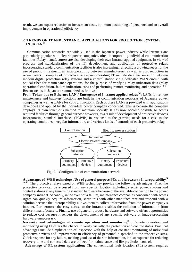
result, we can expect reduction of investment costs, optimum positioning of personnel and an overall improvement in operational efficiency. 2. TRENDS OF IT AND INTRANET APPLICATIONS FOR PROTECTION SYSTEMS
IN JAPAN [1]
Communication networks are widely used in the Japanese power industry while Intranets are
particularly popular with electric power companies, often incorporating individual communication facilities. Relay manufacturers are also developing their own Intranet applied equipment. In view of progress and standardization of the IT, development and application of protective relays incorporating standard communication facilities is also increasing, reflecting a growing needs for the use of public infrastructures, interoperability between manufacturers, as well as cost reduction in recent years. Examples of protective relays incorporating IT include data transmission between modern digital protection relay systems and a control station via a dedicated WAN circuit with optical fiber for maintenance operations, for the purpose of verifying relay indication data (relay operational condition, failure indication, etc.) and performing remote monitoring and operation. [2] Recent trends in Japan are summarized as follows; From Token-bus to Ethernet LAN / Emergence of Intranet applied relays[3]: LANs for remote maintenance and back-up functions are built in the communication networks of Japanese power companies as well as LANs for control functions. Each of these LANs is provided with applications developed and applied by the individual power company concerned. This is because the company employs its own token-bus method to maintain security. It has now become possible to access required facilities through general purpose browsers, as a result of development of protective devices incorporating standard interfaces (TCP/IP) in response to the growing needs for access to the operating conditions, irregular information, and various kinds of controls of each protective relay.
Fig. 2.1 Configuration of communication network Advantages of WEB technology /Use of general purpose PCs and browsers / Interoperability[4
to 6]: The protective relays based on WEB technology provide the following advantages. First, the protective relay can be accessed from any specific location including electric power stations and control stations at any time using standard hardware because of the available connection to the power company intranet. Secondly, in the event of a failure, maintenance companies concerned with access rights can quickly acquire information, share this with other manufacturers and respond with a solution because the interoperability allows them to collect information from the power company’s intranet. Furthermore, the easy access to the intranet enables the collation of information from different manufacturers. Finally, use of general-purpose hardware and software offers opportunities to reduce cost because it renders the development of any specific software or image-processing hardware unnecessary. Necessity and advantages of remote operation and monitoring[7]: Remote operation and monitoring using IT offers the chance to verify visually the protection and control status. Practical advantages include simplification of inspection with the help of constant monitoring of individual protective devices and improvement in efficiency of personnel dispatched to the respective sites. Quick response for any failure, making good use of the site information, is also expected for reducing recovery time and collected data are utilized for maintenance and life prediction control.
Advantage of FL system application: The conventional fault location (FL) system requires
Intranet of Electric Power Company
Control station Electric power station
Primary equipment
Protective devices
Substationnetwork
Primary equipment
Protective devices
Substationnetwork

R o u ter
M O D E M
E th er n et L A NE xc lu s ive C h an n el O p tica l L A N(L A N for C o n tro l)R o u te rM O D E M
S u b sta tio nM a in ten a n ce C en ter C o n t r o l E q u ip m e n t
P ro te c tio n R e la y
DAC IMCS ITC
DAC DAC DAC
F i 3 1 I l i d (1 )
on-site system installation to enable calculation of the fault point based on voltage and current information, and output the results externally. The application of the intranet technology to this will help to reduce the cost considerably since it eliminates the need to install the FL system on–site. Rather, it can collect the necessary information, including voltage and current, from the protective devices to the general purpose PC via intranet through the interface device. 3. PRACTICAL APPLICATIONS OF INTRANET TECHNOLOGIES The growing intranet technologies have already been applied practically to power system protection management. Two examples of these in Japanese power system applications are described below. One is the application to an existing substation and the other is to a newly-constructed substation. 3.1 Application to an Existing Substation The first example is an intranet technology application of a remote maintenance supporting system applied to an existing substation that has been operated practically since 1999. Details are as follows: System Configuration Figure 3.1 shows the system configuration. Protection and control equipment in the substation, connected to a common Ethernet LAN, are the targets of remote maintenance. The common LAN is connected to the maintenance center by an exclusive data transmission channel. In the maintenance center, server computers for remote maintenance are properly equipped and the related substations can be accessed through them. Data security from the public is secured because the data transmission channels, owned by the utilities themselves, are separated physically. The data transmission channels are still available during power system failure because their power is supplied by a battery. Targets for remote maintenance include existing digital protection and control equipment, wherein connection to the new system is easily performed by replacing HI (Human Interface) boards with new network-interface boards. For the new system, the cost reduction of construction by adopting general-use technologies is a great advantage, as well as the improvement in efficiency of the maintenance duties. The main functions of this new system are remote maintenance supporting functions and fault location. In this paper, the former functions are focused on as follows: Maintenance supporting functions The maintenance supporting functions in this system are listed in Table 3.1. As shown in the table, there are differences in permitted functions between remote and local operations. For security reasons setting change work is forbidden in the remote operations. For local operations, all view and operational functions are permitted, including writing new setting values. However, operation of relay with new setting values can
Fig.3.1 Intranet applied system (1)
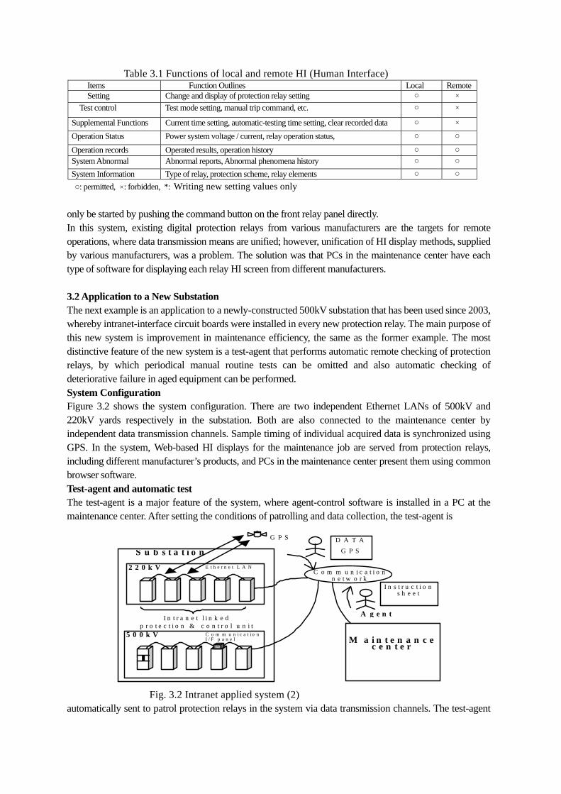
Table 3.1 Functions of local and remote HI (Human Interface) Items Function Outlines Local Remote Setting Change and display of protection relay setting �○ ×
Test control Test mode setting, manual trip command, etc. ○ ×
Supplemental Functions Current time setting, automatic-testing time setting, clear recorded data ○ × Operation Status Power system voltage / current, relay operation status, ○ ○
Operation records Operated results, operation history ○ ○ System Abnormal Abnormal reports, Abnormal phenomena history ○ ○ System Information Type of relay, protection scheme, relay elements ○ ○ ○: permitted, ×: forbidden, *: Writing new setting values only
only be started by pushing the command button on the front relay panel directly. In this system, existing digital protection relays from various manufacturers are the targets for remote operations, where data transmission means are unified; however, unification of HI display methods, supplied by various manufacturers, was a problem. The solution was that PCs in the maintenance center have each type of software for displaying each relay HI screen from different manufacturers. 3.2 Application to a New Substation The next example is an application to a newly-constructed 500kV substation that has been used since 2003, whereby intranet-interface circuit boards were installed in every new protection relay. The main purpose of this new system is improvement in maintenance efficiency, the same as the former example. The most distinctive feature of the new system is a test-agent that performs automatic remote checking of protection relays, by which periodical manual routine tests can be omitted and also automatic checking of deteriorative failure in aged equipment can be performed. System Configuration Figure 3.2 shows the system configuration. There are two independent Ethernet LANs of 500kV and 220kV yards respectively in the substation. Both are also connected to the maintenance center by independent data transmission channels. Sample timing of individual acquired data is synchronized using GPS. In the system, Web-based HI displays for the maintenance job are served from protection relays, including different manufacturer’s products, and PCs in the maintenance center present them using common browser software. Test-agent and automatic test The test-agent is a major feature of the system, where agent-control software is installed in a PC at the maintenance center. After setting the conditions of patrolling and data collection, the test-agent is
Fig. 3.2 Intranet applied system (2) automatically sent to patrol protection relays in the system via data transmission channels. The test-agent
C o m m u n i c a t i o n n e t w o r k
I n s t r u c t i o n s h e e t
D A T A
A g e n t
G P S
M a i n t e n a n c e
c e n t e r
S u b s t a t i o n
I n t r a n e t l i n k e d p r o t e c t i o n & c o n t r o l u n i t
2 2 0 k V E t h e r n e t L A N
5 0 0 k V C o m m u n i c a t i o n I / F p a n e l
G P S

collects information about power system voltage/current, equipment status, etc. during the patrol, then edits/evaluates the data and automatically makes a report after returning to the maintenance center. Though the self-diagnosis ability is one of the main features of digital relays, periodical manual tests are inevitable in conventional relays because there is a limitation in the precision of self-diagnosis. The aim of this test-agent scheme is to omit the manual maintenance by its high precision self-checking ability. The following two methods are adopted for the self-checking of analogue circuits in the test-agent scheme. The comparative check method provides precise checking performance. The higher harmonic method is a supplemental method which is less precise and is effective when the comparative check is unavailable because of no load current. Comparative check method; Most of the Japanese protection systems for trunk power systems are duplicated. In the comparative check method, the same data acquired in the double system are compared and checked to detect any difference between them. If the relative error ratio, defined by (1), has a trend of increasing more than a certain level, the test-agent judges that a failure exists.
X=ABS(IA-IB)/ABS(IA+IB) (1) Where, IA: current in A-system, IB: current in B-system, X: relative error ratio
When a failure is indicated by (1), three-phase balances of voltage and current are checked in each system, considering the less balanced system is on the failure side. Higher harmonic method; Higher harmonics are superimposed on analogue circuits for checking, which is a widely used method. The superimposed higher harmonics are converted into digital and checked by software to monitor the analogue input circuit. Generally, the fourth harmonics are used, which do not affect the protection performance because they can be entirely eliminated by a digital filter in the software. When there is a difference between the input and calculated value, a failure exists. Trends of the checked results of the comparative and higher harmonic methods can be displayed graphically. The deteriorating tendency of aged equipment can obviously be observed by these trend displays, which will be very useful for preventive maintenance and for determining the refurbishing time. 4. INTRANET TECHNOLOGIES AND COMMUNICATION SECURITY 4.1 Scope of Remote Operation System for Protection Relay using Intranet Technology Conventionally, only the limited information required for operation was transmitted from protection relays to remote operation and maintenance centers, owing to restrictions of the network. However, recently a large quantity of varied information has come to be treated at remote operation and maintenance centers in conjunction with a background of advancement in information network technologies, expansion of telecommunication infrastructures and improvement of protection relay functions. The range of the remote operation systems for protection relays is shown in figure 4.1, where two kinds of Human Interfaces (HIs) exist. Local HI: in a substation yard where protection relays are installed. Remote HI: in a maintenance center for maintenance and dispatch and control center for operation. Due to the use of remote operation and maintenance systems, efficiency of operation and maintenance work has been greatly improved, such that setting change and status control of protection relays are possible without moving from the operation and maintenance center. Moreover, improvement in response time for system failure is expected. 4.2 Communication Security Measures
In general, information is transmitted via various kinds of transmission routes in a communication network that cause deterioration of communication security; tapping, alteration, destruction of

Fig. 4.1 Scope of Remote Operation System for Protection Relay
information by external network users. To prevent these invasions upon the networks, measures for communication security are needed. In Japan, power utilities have their own exclusive communications networks, and a part of them are used for protection and control systems. In these exclusive networks, intranet technologies are also applied to the protection and control systems, including for remote monitoring and operation. The followings are examples of measures for communication security in the remote operation systems of protection relays.
Exclusive-use of a network: the network for the remote operation system is dissociated physically from the other general business-use communication networks, preventing unlawful access from external society. Functional restriction on remote HI: In some applications, operations that can affect the protection functions such as setting, testing are omitted from the remote HI menu, so that protection relays may not be operated improperly in the event that the remote operation system is invaded. An example of the restricted functions is shown in Table 3.1.
Redundancy in operation command: In some applications, important operations such as setting change command are composed with the other redundant signals for security reasons. Fig. 4.2 shows an example of the setting change flowchart. After sending new setting values from the remote HI, a command for “restarting with new setting value” is sent via another dependant tele-control network.
Fig. 4.2 Redundancy of Operation Start Command

4.3 Countermeasures against Network Interruptions Network interruptions including hardware failures in communication apparatus are inevitable in intranet communications. The followings are general countermeasures for the interruptions; Separation of protection functions from the network: protection functions should be separated from the network interface functions in both hardware and software to prevent any failures due to network interruptions. Direct connection of HI personal computer: HI personal computer should be connected directly, in the case of network interruptions. Functions for network disconnection: Proper functions to cope with sudden network disconnection should be provided. Data Preservation of operation history: Data of relay operation history or system problems should not be lost during network interruptions. 5. CONCLUSION This paper showed that an intranet applied system improves operational efficiency including reduction of restoration time following system disturbances. At present, limited experience exists in practical applications of intranet technologies to power system protection and control because they are comparatively new techniques, and it has only been a short time since they were introduced within power systems. However, they have great potential, and in the near future they promise to perform important roles in the power system protection and control area. 6. REFERENCES [1] Kido et al: “Application of IT technology to protection relay system”, PSR-02-4 IEEJ [2] Ad hoc Committee for The 21 Century Transformation Technology: “Transformation Technology of the 21 Century”, Electric Technology Research Association Japan, No. 2, Vol. 58 [3] Yamashiro et al: “Progress of Element Technology applicable to Protective Relay System”, PSR-01-16 IEEJ [4] Maehara et al: “Transformer Station Facility Control System applied with Network Computing Terminal”, PSR-02-9 IEEJ [5] Sato et al: “Study on Maintenance Operation Support System for Digital Protective Control Device”, General Convention of the Institute of Electric Engineers of Japan, 2003, 6-276. [6] Tanaka et al: Effectiveness Improvement of Facility Security utilizing IT Technology [7] Nakahara et al: “Efficiency Improvement of Operating Maintenance realizable by Networking of Protective Relay and its Multi-function” PSR-02-5 IEEJ