Embed Size (px)
Citation preview

,f Hydraulic
·h.D. Thesis,
•ree-Surface
:1gemittelten
viiinchen (in
allow Water
ntersuchung
'TH Aachen,
: Sons, Ltd.,
•VM for 2D92-702
Hydraulics of Dams and River Structures - Yazdandoost & Attari (eds) @ 2004 Taylor & Francis Group, London, ISBN 90 5809 632 7
Application of a Boussinesq-type equation to flow over trapezoidal profile weirs
Y.T. Zerihun & J.D. Fenton Department of Civil and Environmental Engineering, The University of Melbourne, Australia
ABSTRACT: Flow over embankment shaped weirs commonly encountered in large 2-D flow problems cannot be simulated by most of the common flow models which assume uniform velocity and hydrostatic pressure distributions. A Boussinesq-type momentum equation, which allows for curvature of the free surface and a non-hydrostatic pressure distribution, is considered in this paper for the numerical simulation of steady flow over short- and broad-crested trapezoidal profile weirs as well as for the establishment of head-discharge relationships under free flow conditions. An implicit finite difference scheme is applied. Computed and measured results of flow surface profiles and rating curves for these types of weirs are presented. The numerical results of the flow surface profiles and rating curves show good agreement with the corresponding experimental data. The model results also demonstrate the detailed dependence of the flow characteristics of these weirs on the curvature of the streamlines.
INTRODUCTION
Flood flows over highway and railway embankments are analogous to flow over short- and broadcrested weirs. The hydraulic advantage of higher discharge capacity of these trapezoidal profile weirs compared to broad-crested weirs with vertical faces makes them very attractive in practice as a discharge measuring device. Thus, the development of head-discharge relationships of such weirs assumes considerable practical importance. Also in the applications of two-dimensional flow models, these weirs often provide important boundary conditions. However, flow over such types of weirs cannot be simulated by most of the common flow models, which assume uniform velocity and hydrostatic pressure distributions over the depth. These assumptions restrict the application of the models to flow simulation problems that involve insignificant curvature of streamlines. These models do not retain accuracy for flow situations where the effects of non-hydrostatic pressure distribution are significant and essential, such as rapidly varied flows past hydraulic structures. The two-dimensional nature of this flow problem requires relatively accurate methods for exact simulation of the flow situation. In this study a model based on a higher-order Boussinesq-type equation will be employed for the simulation of such types of flow problem numerically.
A review of the literature shows that little effort has been made to study the numerical modelling of flow over trapezoidal profile weirs particularly for the establishment of rating curves. Contrary to this, the problem of flow over such weirs has been extensively studied experim�ntally. Most of the experimental works were performed towards the understanding of the flow characteristics of these weirs and also the determination of the coefficients of discharge under free and submerged flow conditions (see e.g. Kindsvater 1964, Fritz & Hager 1998). A simple numerical procedure was applied to develop rating curves for flow over broad-crested weirs by incorporating directly the discharge coefficients. The procedure was formulated based on the energy equation which assumes uniform flow at the gauging station and control section, and constant head between this station and section (see Bos 1985 #3.7). This rating procedure provides solution to irrotational flow problems with negligible curvature of streamlines since its application is limited by the ratio of the total energy head, Ho, to weir crest length, Lw (Ho/Lw ::: 0.50). However, the procedure is inappropriate to develop a rating curve for flow over short-crested weirs where the effects of non-hydrostatic pressure and non-uniform velocity distributions are significant. More recently Collins & Catalano (2001) studied the ability of the DELFT-FLS model to predict accurately the crest-referenced head
369

of a broad-crested weir. The study aimed to explore the capabilities and limitations of the model. The discharge rating curves of the weir were simulated for free flow condition and the predicted results were compared with the results of the common broad-crested weir formula for the range in which this equation estimates the discharge accurately (0.08:::; Ho/ Lw :'S 0.33). However, the study did not include flow simulations over short-crested weirs (0.33 < Ho/ Lw :'S 1.50) where the curvature of the streamlines above the weir crest has a considerable influence on the head-discharge relationships. This review demonstrates that a general model, which includes the effects of the curvature of the streamlines implicitly or explicitly, is necessary to provide head-discharge relationships for shortand broad-crested weirs. In this work a numerical model based on a higher-order equation will be used for flow simulation over trapezoidal profile weirs with smooth transition curves introduced at the four corners of the profile for the purpose of integrating the equation continuously at these points.
Therefore the main objectives of this paper are: (i) to model transcritical flow over trapezoidal profile weirs using a higher-order equation numerically for establishing head-discharge relationships; (ii) to assess the influence of the curvature of the streamlines on the head-discharge relationshipsas well as on the flow profile solutions of the governing equation; (iii) to examine the accuracy of the model results by a number of laboratory experiments.
2 GOVERNING EQUATION
Fenton (1996) developed a Boussinesq-type momentum equation based on the assumption of a constant centrifugal term at a vertical section to model relatively short length scale flow problems. For steady flow in a rectangular channel, the equation reads as
(1)
in which H is the depth of flow; Z�, z; and z;' are the first, second and third derivatives of the bed profile respectively; Sf denotes the friction slope, calculated from the Manning equation or smooth boundary resistance law; q is the discharge per unit width; f3 refers to the Boussinesq coefficient; g is gravitational acceleration; and wo is a constant factor to reflect the effect of the bed in determining the elevation of the surface and the associated dynamic pressures due to slow moving flow near the bottom of the flow boundary. Fenton (1996) suggested a value of slightly less than one for wo. In the formulation of this equation, the curvature, K, at the surface is approximated
2 2 II II
byK�d H/dx +zb and at the bed byK�Z. This equation implicitly includes the effect of the vertical acceleration to model two-dimensional
flow problems where more vertical details are significant and essential. For the case of weakly curved free surface flow with negligible curvature of streamlines in a constant slope channel, -the flow surface and bed curvatures terms vanish to zero. Under this flow condition, the above equation reduces to the gradually varied flow equation. Equation (1) will be used in this study to simulate transcritical flow over trapezoidal profile weirs for the purpose of developing discharge rating curves. These weir profiles are characterized by the presence of discontinuous bed geometry properties at the four corner points. Smooth transition curves should be fitted at these points in order to integrate equation (1) continuously within the solution domain. A simple curve described by a polynomial function of degree five was used. The length of this curve was fixed based on the criteria that the error associated with the prediction of the bed profile elevation around the discontinuous point is less than 5%.
3 PROBLEM FORMUL.:A..TION
The computational domain for the numerical solution of the weir flow problem is shown in Figurel . In this figure AB is the inflow section, CD is the outflow section and BM is the approaching channel
370
A
B
j=O
Figure I. Co
bed.Also, M is located in ; hydrostatic p of the soluti< gradually va1 of the water:
in which Fr of the weir, 1 approximatio (2) with respt
where K is th, the channel. 1 weir to avoid overflow dept of the followi from the upst of the embanl overflow heac simulation pr, embankment
For the giv1 flow surfacer purpose, the c in Figure I.
4 DEVELOl
Finite differen This formulati tial equations. equation as

:model.The icted results ge in which tudy did not vature of the :lationships. 1ature of the JS for shortition will be , introduced .1sly at these
,ezoidal pro:lationships; ·elationshipsaccuracy of
1mption of a w problems.
)) (1)
atives of the ; equation or : Boussinesq effect of the ; due to slow f slightly less .pproximated
-dimensionalse of weaklyope channel,m, the abovethis study tong discharge,ed geometryese points in:ve described>ted based onn around the
m in Figurel. :hing channel
G z
•NodesAi-------i---------i-----
------1C Bf---4�-:;f:==�:--+-....::.:...--·
j=O D
i=J
h s
Gauging station-GS
Figure 1. Computational domain for flow over weir.
bed. Also, MUVN is the trapezoidal profile weir. The inflow section of the computational domain is located in a region where the flow is assumed to be nearly horizontal, with uniform velocity and hydrostatic pressure distributions. This pseudo-uniform flow condition before the inflow section of the solution domain simplifies the evaluation of the boundary values at this section using the gradually varied flow equation, equation (2). Thus, for a given depth at the inflow section the slope of the water surface, dH / dx, can be evaluated from the following equation
dH dx
So-Sf
1 - f3Fr2'
(2)
in which Fr is the Froude number; and So is the bed slope. For the subcritical flow upstream of the weir, the Froude number squared is sufficiently small and can be neglected. Using this approximation, the curvature of the flow surface, Ks , at inflow section after differentiating equation (2) with respect to x becomes
-2q2B2 dK dHKs = K3 dH dx' (3)
where K is the conveyance factor, can be determined from the Manning equation; B is the width ofthe channel. Similarly, the gauging station GS should be situated sufficiently far upstream of theweir to avoid the influence of the curvature of the water surface on the magnitude of the estimatedoverflow depth. According to Bos et al. (1984 p. 36) this section is located at a distance of the largerof the following two values: (i) between two and three times the maximum crest referenced headfrom the upstream edge of the weir crest; (ii) the maximum crest referenced head from the heelof the embankment shaped weir. From the computational point of view, however, the maximumoverflow head is not known a priori to fix the position of the gauging station. For this numericalsimulation problem, the overflow head corresponding to the given discharge at the heel of theembankment shaped weir will be used to locate approximately the gauging station. For the given flow depth, AB, and discharge at the inflow section, it is required to determine theflow surface profile, AC, and the corresponding overflow head at the gauging station GS. For thispurpose, the computational domainACDNVUMB is discretized into equal size steps in x as shownin Figure l.
4 DEVELOPMENT OF THE NUMERICAL MODEL
Finite difference approximations are used to replace the derivative terms in the above flow equation. This formulation is very simple to code and extensively used to solve linear or non-linear differential equations. For the purpose of discretization, equation (1) can be represented by a simple general equation as
(4)
371

where 50, 51 and 52 are the non-linear coefficients associated with the equation. It is a third-order differential equation which needs to employ third- or higher-order accurate methods to solve the equation numerically. This is necessary in order to reduce the truncation errors introduced in the formulation due to the finite difference approximation of the derivative terms of the equation (see Abbott 1979 #4.12). Therefore, five point finite difference approximations are employed here to replace the derivative terms in the governing equation. The upwind finite-difference approximations (Bickley 1941) for derivatives at node j in terms of the nodal values atj-3,j-2,j- l ,j and,}+ 1 are introduced into equation (4) for the purpose of discretising the equation. After simplifying the resulting expression and assembling similar terms together, the equivalent finite difference equation reads as H.i-3 (12 - 250,Jh - 251,;h2) + H.i-2 (-72 + 850,Jh + l251,;h2)
+ H.i-1 (144 + 1250,Jh - 3651,Jh2) + H.i (-120 - 4050,Jh + 2051,Jh2)+ H.i+1(36 + 2250,Jh + 651,Jh2) + 2452,;h3 = 0, (5)
where his the size of the step. In the solution domain, equation ( 5) is applied to evaluate nodal values at different points. However, the use of equation (5) at}= 1 and} =J will introduce unknowns external to the computational domain. Using the backward difference approximations in terms of nodal points}, J-1, j-2, ... for the derivative terms in equation (4), the finite difference equation at the outflow section after simplifying the resulting expression becomes H.i-4 (36 + 2250,Jh + 651,;h2
) + H.i-3 (-168 - 11250,;h - 3251,;h2)
+ H.i-2 (288 + 22850,Jh + 7251,;h2) + H.i-1 (-216 - 20850,Jh - 9651,;h2)
+ H.i ( 60 + 7050,Jh + 5051,;h2) + 2452,;h3 = 0. (6) Since the value of the nodal points at j = 0 is known, the values of the imaginary nodes at j = -1 and j = -2 can be determined from the estimated water surface slope, S H, and curvature of the free surface, KH, at the inflow section. Using similar discretization equations as above for the water surface slope and curvature at inflow section and the expanded form of equation (5) at}= 0, the explicit expressions for the nodal value at j = -l and j = -2 are
where:
H-2 = 6hSH + l2H-1 - l5Ho + 4H1 - 6h2KH, (7) H-1 = (-1 -) (A (24hSH - 80Ho + 21H1 - 36h2KH) + B (6hSH - 15Ho))' (8) <I> - Q + B (4H1 - 6h2KH) +H1E +Hof+ Y
A= 6h251,o + 22h50,o + 36; B = 20h2ho - 40h50,o - 120; Q = 36h251,o + 12h50,o + 144; <I> = -54A - 12B; E = -2h251,o - 2h50,o + 12; r = I2h2ho + 8h50,o - 72; Y = 24h352,o.
The solution of the non-linear flow equation based on a boundary value technique requires an initial estimate of the position of the free surface profile. This makes the solution of the flow problems relatively more difficult due to the fact that the location of the free surface profile is not known a priori. Generally, such problems must be solved by iterative methods, which proceed from an assumed initial free surface position. Convergence of the iteration procedure to a final profile that satisfies the boundary condition may be dependent to some extent on the choice of the initial flow surface profile. In this work the Bernoulli and conti1:mity equations are employed to obtain the initial flow surface profile for commencing the iteration solution. To simulate the flow surface profile, equations ( 5) and ( 6) are applied at different nodal points within the solution domain and this results a sparse system of non-linear algebraic equations. These equations together with equations (7) and (8), and a boundary value at the inflow section, are solved by the Newton-Raphson iterative method 372
with a numer criterion:
where lil{_j is 1 is the total nu case study, a t head at the g, known height ( 5), ( 6), (7) a1 5 EXPERI� The experime wide in the D The flume anc head tank frm Various flow i a smooth flo� high, crest Jen discharges. A volumetr plan dimensio the horizontal; used to minim flow surface p recording the centreline of t much closer n water piezomt base reading fi to the criteria l experimental r
6 RESULTS In this work th, steady flow ovt order to assess· with different degree of the c the streamline Bos 1978 p. 1'. resistance law 1 simplicity /J is were independt The compar over short- and is seen betwee1 critical flow re1 This numerical irrespective of curvature appn
:hird-order > solve theteed in the 1ation (see ,ed here to
in terms of purpose of nilar terms
(5)
odal values , unknowns in terms of ce equation
) (6)
es atj = -1 ature of the 'or the water atj=O, the
(7)
'o))' (8)
+ 12;
ires an initial ow problems is not known ;eed from an ii profile that 1e initial flow tain the initial rface profile, nd this results ations (7) and rative method
with a numerical Jacobian matrix. The convergence of the solution is assessed using the following criterion:
m
L j8Hjj :'.S tolerance,
J=I
where 8Hj is the correction depth to the solution of the nodal point} at any stage in the iteration; mis the total number of nodes in the solution domain excluding nodes having known values. In this case study, a tolerance of 1 o-6 is used for the convergence of the numerical solution. The overflowhead at the gauging station can be determined from the predicted flow depth at this station and a known height of the trapezoidal profile weir above the upstream floor level. In this model equations (5), (6), (7) and (8) constitute the one-dimensional finite difference equivalent equations.
5 EXPERIMENTAL SET-UP AND PROCEDURE
The experiments were performed in a horizontal flume 7100 mm long, 3 80 mm high, and 3 00 mm wide in the Department of Civil and Environmental Engineering at the University of Melbourne. The flume and the trapezoidal profile weirs were made of Plexiglass. The water was supplied to the head tank from a sump through 115 mm diameter pipe with a valve for controlling the discharge. Various flow improving elements were provided upstream of the trapezoidal profile weirs to obtain a smooth flow without large-scale turbulence. Symmetrical trapezoidal profile weirs of 150 mm high, crest length 100 mm and 400 mm respectively and side slope 1 V:2H were tested at different discharges.
A volumetric tank system was used to measure the discharge. The system consists of a tank with plan dimensions of200 cm by 150 cm and depth of 450 cm, and an inclined manometer (56.62° to the horizontal) for water level measurement in the tank. Tank filling time longer than one minute was used to minimize errors associated with the starting and stopping of the stopwatch. The longitudinal flow surface profile was observed with a manual point gauge of reading accuracy ±0.10 mm. For recording the bed pressure, steel pressure taps of external diameter 3 mm were fixed along the centreline of the weir model with maximum horizontal spacing of 100 mm, but the spacing was much closer near to the edges of the weir crest. These pressure taps were connected to vertical water piezometers of reading accuracy to 1 mm by long plastic tubes. For each experiment, the base reading for the pressure taps was obtained immediately after the flow was shut off. According to the criteria given by Ranga Raju et al. ( 1990), the effects of viscosity and surface tension on the experimental results were negligible.
6 RESULTS AND DISCUSSION
In this work the numerical model, which was developed in the previous section, is used to simulate steady flow over short- and broad-crested trapezoidal profile weirs for transcritical flow situation. In order to assess the effect of the streamline curvature on the solution of the model, free flow situations with different Ho/Lw values were considered. The magnitude of this ratio directly measures the degree of the curvature of the flow over the crest of the weir. For Ho/ Lw :'.S 0.50, the curvature of the streamline over the crest is insignificant except near to the edges of the weir crest (see e.g. Bos 1978 p. 15). Since the experiment was performed in a laboratory flume, a smooth boundary resistance law was applied to estimate the friction slope for the numerical model. For computational simplicity f3 is taken as unity in the above flow equation. All computational results presented here were independent of the effect of spatial step size.
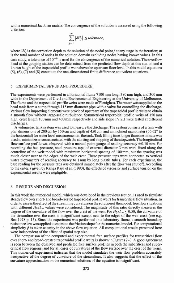
The comparison of the computed and experimental free surface profiles for transcritical flow over short- and broad-crested trapezoidal profile weirs is shown in Figures 2-3. A good agreement is seen between the observed and predicted free surface profiles in both the subcritical and supercritical flow regions, and for all cases of curvatures of the flow surface over the crest of the weirs. This numerical experiment indicates that the model simulates the weir flow problem accurately irrespective of the degree of curvature of the streamlines. It also suggests that the effect of the curvature approximation on the numerical solutions of the equation is insignificant.
373

0.4
Weir crest length= 10 cm (a)
g 0.2
� ="' :!:: 0
0ri: --- Bed profile - · - · - · Predicted (Ho/Lw=0.463)--- Predicted (Ho/Lw=0.795)
I!. Measured -0.2
-1 -0.5 0 0.5 1.5
Horizontal distance (m)
0.4
Weir crest length= 10 cm (b)
l!.··i:J.-·i:J.--i:J.··i:J.··i:J.-1:J,Mi:J.-t,.-t,.�
g 0.2 � ... 'I!. ...
� ="' :!:: 0
0ri: --- Bed profile
--- Predicted (Ho/Lw = 0.544)
· Predicted (Ho/Lw=0.952)
I!. Measured-0.2
-1 -0.5 0 0.5 1.5
Horizontal distance (m)
Figure 2. Flow surface profiles for free flow over short-crested weir.
The computed head-discharge curves obtained for the case of flow over trapezoidal profile weirs is compared with the experimental results in Figure 4. The numerical solutions demonstrate good agreement with the experimental data for both weirs. This figure also compares the simulated discharge rating curves of the short- and broad-crested type of trapezoidal profile weirs. Depending on the magnitude of Ho/ Lw, the same type weir can act as a broad-crested or a short-crested weir. At low flow rates the rating curve for the short- and broad-crested type of trapezoidal profile weirs are identical; indicating the insignificance of the influence of the curvature of the streamlines on the discharge characteristics of both weirs at this level of the flow rates (see Fig. 4). As the discharge increases, clear differences between the head-discharge curves of the broad-crested and shortcrested weirs are observed. This difference is due to the large increase of curvature of the streamlines of the flow over the crest of the short-crested trapezoidal profile weir. It can be observed from Figure 4 that in the region of relatively high flow rate, the overflow depth required to pass the given discharge over the broad-crested weir is larger than the corresponding overflow depth for the short-crested weir. This implies that less energy is required to pass a given flow over the short-crested types than the broad-crested weirs. This result suggests that the curvature of the streamlines of the flow over the crest of the trapezoidal profile weir has significant impact on the discharge capacity of the weir.
7 CONCLUSIONS
A numerical model has been developed using a higher-order Boussinesq-type momentum equation to simulate transcritical flow over short- and broad-crested trapezoidal profile weirs as well as to
374
0.4-
g 0.2-... ...
="' :!::
� 0-
-0.2-
0.4.
g 0.2
...
� ="' :!::
ri: 0
-0.2 ·
Figure 3. H
Figure4. Di

1.5
b)
1.5
:zoidal profile tS demonstrate ; the simulated irs. Depending rested weir. At ofile weirs are 1mlines on the : the discharge ted and shorthe streamlines �d from Figure iven discharge : short-crested ;ted types than f the flow over ity of the weir.
ntum equation s as well as to
0.4�---------------------------,
! 0.2
�
="'
£ 0
Weir crest length= 40 cm
- Bed profile--- Predicted (Ho/Lw=0.196)
--- Predicted (Ho/Lw=0.250)
6 Measured
(a)
-0.2 +-----,------.-----.----.-----,-----, -1 -0.5 0 0.5 1.5 2
Horizontal distance (m)
0.4 -,-------------------------------
! 0.2
�
="'
£ 0
Weir crest length= 40 cm
---Bed profile ---Predicted (Ho/Lw = 0.220) ---Predicted (Ho/Lw = 0.267)
6 Measured
(b)
-0.2 -+-----�----�----�----..-----,------, -1 -0.5 0 0.5
Horizontal distance (m)
Figure 3. Flow surface profiles for free flow over broad-crested weir.
14
- 12
-= 10
1 8
1 6
0 4
2
- - • - · Predicted (Lw = 10 cm)
----0-- Measured (Lw = 10 cm)
- ·•··Predicted (Lw=40 cm)
1.5
ou------,-----...-----,-----.-----.-----1
0 5 10 15
Discharge (Us)
20 25
Figure 4. Discharge rating curves for the short- and broad-crested trapezoidal profile weirs.
375
30
2

predict the upstream overflow depths for the given discharges for the purpose of establishing headdischarge relationships for these weirs. It should be emphasized that this one-dimensional model is capable of treating free flow over any type of weir profile providing the profile does not have vertical faces. Analysis of numerical and experimental results was also presented. Good agreement was observed between the predicted and measured values. The model predicts accurately the free surface profiles regardless of the curvature of the streamlines. The model result also shows the influence of the curvature of the streamlines on the discharge characteristics of the trapezoidal profile weirs. The existing flow model for developing discharge rating curves under free flow condition, which is valid only for broad-crested weir, was extended using the Boussinesq-type momentum equation model.
REFERENCES
Abbott, M.B. 1979. Computational Hydraulics; Elements of the Free Surface Flow. London: Pitman Publishing limited.
Bickley, WG. 1941. Formulae for Numerical Differentiation. Math. Gaz. 25: 19-27.
Bos, M.G. (2nd ed.) 1978. Discharge measurement structures. Wageningen: ILRI. Bos, M.G., Replogle, J.A. & Clemmens, A.J. 1984. Flow Measuring Flumes for Open Channel Systems.
New York: John Wiley & Sons.
Bos, M.G. 1985. Long-throated Flumes and Broad-crested Weirs. Dordrecht: Martinus NijhoIDDr. W Junk Publishers.
Collins, N. & Catalano, C. 2001. Specialized 2-D modelling in floodplains with steep hydraulic gradients. Proc. Conf on Hydraulics in Civil Engrg., Hobart, 28-30 November, The Institution of Engineers, Australia.
Fenton, J.D. 1996. Channel flow over curved boundaries and a new hydraulic theory. Proc. I 0th congress, Asia and Pacific Division of the JAHR, Langkawi, 26-29 August, Malaysia, 2: 266-273.
Fritz, H.M. & Hager, H.W 1998. Hydraulics of embankment weirs. J. Hydr. Engrg., ASCE, 124(9): 963-971. Kindsvater, C.E. 1964. Discharge characteristics of embankment shaped weirs. Geological Survey Water Supply
Paper 1617-A. Washington: U.S. Government Printing Office. Ranga Raju, K.G., Srivastava, R. & Porey, P.D. 1990. Scale effects in modelling flows over broad-crested weirs.
Journal of Irrigation and Power, 47(30): 101-106.
376
Hydrod
B. FirooziMechanicai
ABSTRA< rectangula ACFD crn dimension diffusion a finite volu of the com with thee profiles ar, a normal i
lateral pro] a physical
INTRC
Density ct flows, whi homogene mechanisn currents ai
and pyrocl Drivent
the turbidc This flowc by a thinrn analysis re rise above1 increases.
In hydra has been it 2-D turbiddue to watfdirection. Jrestriction,longitudirnthe vertica
This par currents w: compared·
2 GOVEJ
Figure 1 sl of the ligh1